Axxess Stereos Installation Instructions - CARiD.com · Cycle the key by turning the ignition on...
4
INSTALLATION INSTRUCTIONS FOR PART LC-GMRC-01 ISO • Cutting tool • Crimping tool • Tape • Connectors (example: butt-connectors, bell caps, etc.) TOOLS REQUIRED GM Class II Data Bus Interface 2000-up LC-GMRC-01 • LC-GMRC-01 class II chime retention interface • Harness INTERFACE COMPONENTS KIT FEATURES APPLICATIONS • Provides accessory (12 volt 3 amp) • Retains RAP (if equipped) • Used in non-amplified systems or when removing amplified system • Retains all warning chimes • Small in size See inside front cover
Transcript of Axxess Stereos Installation Instructions - CARiD.com · Cycle the key by turning the ignition on...

INSTALLATION INSTRUCTIONS FOR PART LC-GMRC-01
IGNITIONTERM
INALS
WIRE
CUTTER
M3.5
M2.6
M3
M5
M4
ISO
62.5
1.5
• Cutting tool • Crimping tool • Tape • Connectors (example: butt-connectors, bell caps, etc.)
TOOLS REQUIRED
GM Class II Data Bus Interface2000-up
LC-GMRC-01
• LC-GMRC-01 class II chime retention interface • Harness
INTERFACE COMPONENTS
KIT FEATURES
APPLICATIONS
• Provides accessory (12 volt 3 amp)
• Retains RAP (if equipped)
• Used in non-amplified systems or when removing amplified system
• Retains all warning chimes
• Small in size
See inside front cover

Applications
LC-GMRC-01
Caution: Metra recommends disconnecting the negative battery terminal before beginning any installation. All accessories, switches, and especially air bag indicator lights must be plugged in before reconnecting the battery or cycling the ignition.
Note: Refer also to the instructions included with the aftermarket radio.
Note: The LC-GMRC-01 is designed to be used in non-amplified GM vehicles or in vehiclesthat the OEM amplifier has been bypassed; Onstar is not retained in either case. The LC-GMRC-01
retains all the factory warning chimes that would be lost when the OEM radio is removed.It will also provide a 3 amp 12 volt switched accessory for proper radio operation, and retain
the RAP (Retained Accessory Power) feature if equipped.
BuickAllure 2005-2009Century 2004-2005Lacrosse 2005-2009Rainier 2004-2007Rendezvous 2002-2007Terraza 2005-2008
chevroletAvalanche 2003-2006Cavalier 2000-2005Colorado 2004-2010Express 2003-2007 Impala 2000-2005Malibu 2001-2003Malibu classic 2004-2005Monte Carlo 2000-2005Silverado pickup classic 2007Silverado pickup (all models) 2003-2006SSR 2003-2006Suburban 2003-2006Tahoe 2003-2006Trailblazer 2002-2009Uplander 2005-2008Venture van 2000-2005
GMcCanyon 2004-2010Envoy 2002-2009Savanna van (full size) 2003-2007
(GMC continued) Sierra classic 2007Sierra 2003-2006Yukon/Yukon XL 2003-2006
huMMerH3 2006-2009
isuzuAscender 2003-2008I Series pickups 2006-2008
oldsMoBileAlero 2001-2004Bravada 2002-2005Intrigue 2002Silhouette 2000-2004
PontiacAztec 2001-2005 Grand Am 2001-2005 Grand Prix 2004-2008 Montana sv6 (Canada) 2005-2008Montana 2000-2005 Sunfire 2000-2005
saaB9-7X 2005-2009
saturnRelay 2005-2007

• Connect the Yellow wire to the radios constant/memory wire.
• Connect the the red wire to the radios accessory wire.
• Connect the Black wire to the radios ground wire.
• Connect the Blue/White wire to the radios amp or antenna turn on.
• Connect the orange wire to the radios illumination wire. If the radio does not have an illumination wire just tape up the orange wire.
• Connect the orange/White wire to the radios dimmer wire. If the radio does not have a dimmer wire just tape up the orange/White wire.
• Connect the White wire to the radios left front (+) speaker wire.
• Connect the White/Black wire to the radios left front (-) speaker wire.
• Connect the Gray wire to the radios right front (+) speaker wire.
• Connect the Gray/Black wire to the radios right front (-) speaker wire.
• Connect the Green wire to the radios left rear (+) speaker wire.
• Connect the Green/Black wire to the radios left rear (-) speaker wire.
• Connect the Purple wire to the radios right rear (+) speaker wire.
• Connect the Purple/Black wire to the radios right rear (-) speaker wire.
Connections to be made
LC-GMRC-01
LC-GMRC-01
1. With all connections completed reconnect the negative battery terminal.
2. Plug the LC-GMRC-01 into the vehicle and into the radio.
3. Cycle the key by turning the ignition on then back off, then on again.
Testing the LC-GMRC-01
1. Turn the radio on and test for proper balance and fader operation.
2. Close the doors then turn the key off. The radio should stay on until the driver’s door is open.
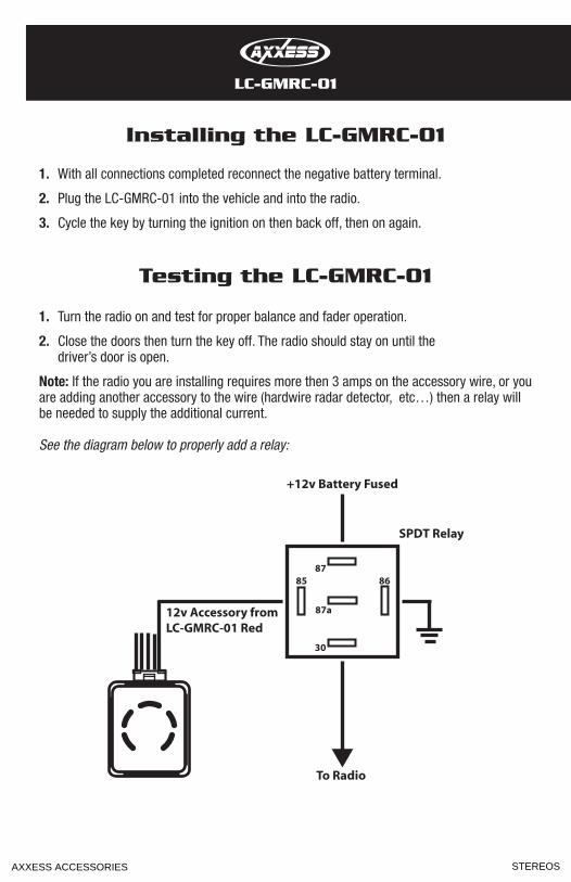
note: If the radio you are installing requires more then 3 amps on the accessory wire, or you are adding another accessory to the wire (hardwire radar detector, etc…) then a relay will be needed to supply the additional current.
See the diagram below to properly add a relay:
Installing the LC-GMRC-01
12v Accessory from LC-GMRC-01 Red
To Radio
SPDT Relay
+12v Battery Fused
8785 86
30
87a
AXXESS ACCESSORIES STEREOS