Axial piston variable pump A15VSO, A15VLO series …...RA-A 92800/11.2013, Bosch Rexroth AG Axial...
60
RA-A 92800/11.2013, Bosch Rexroth AG Features ▶ Variable axial piston pump of swashplate design for hydrostatic drives in open circuit. ▶ For use preferably in stationary applications. ▶ The flow is proportional to the drive speed and displacement. ▶ The flow can be infinitely varied by adjusting the swashplate angle. ▶ The pump can work either self-priming or with a charge pump. ▶ A wide range of highly adaptable control devices with different control and regulating functions for stationary applications. ▶ 100% mooring function possible depending on specific controller (overcenter, operation as a motor). ▶ The universal through drive is suitable for adding gear pumps and axial piston pumps up to the same size, i.e. 100% through drive. ▶ Compact design ▶ High efficiency ▶ High power density ▶ Low noise level ▶ Sizes 110 to 280 ▶ Nominal pressure 5100 psi (350 bar) ▶ Maximum pressure 6100 psi (420 bar) ▶ Open circuit Axial piston variable pump A15VSO, A15VLO series 10 (US-Version) RA-A 92800 Edition: 11.2013 Replaces: –.– Contents Ordering code 2 Hydraulic fluid 5 Shaft seal 6 Charge pump (impeller) 6 Operating pressure range 7 Technical data 8 Power controller 12 Stroke control 16 Pressure controller 23 Dimensions size 110 27 Dimensions size 145 31 Dimensions size 175 35 Dimensions size 210 40 Dimensions size 280 45 Through drive dimensions 50 Overview of attachment options 52 Combination pumps A15V... + A15V... 53 Connector for solenoids 54 Installation instructions 55 General instructions 58
Transcript of Axial piston variable pump A15VSO, A15VLO series …...RA-A 92800/11.2013, Bosch Rexroth AG Axial...

RA-A 92800/11.2013, Bosch Rexroth AG
Features Variable axial piston pump of swashplate design for
hydrostatic drives in open circuit. For use preferably in stationary applications. The fl ow is proportional to the drive speed and
displacement. The fl ow can be infi nitely varied by adjusting the
swashplate angle. The pump can work either self-priming or with a charge
pump. A wide range of highly adaptable control devices with
diff erent control and regulating functions for stationary applications.
100% mooring function possible depending on specifi c controller (overcenter, operation as a motor).
The universal through drive is suitable for adding gear pumps and axial piston pumps up to the same size, i.e. 100% through drive.
Compact design High effi ciency High power density Low noise level
Sizes 110 to 280 Nominal pressure 5100 psi (350 bar) Maximum pressure 6100 psi (420 bar) Open circuit
Axial piston variable pumpA15VSO, A15VLO series 10(US-Version)
RA-A 92800Edition: 11.2013Replaces: –.–
ContentsOrdering code 2Hydraulic fl uid 5Shaft seal 6Charge pump (impeller) 6Operating pressure range 7Technical data 8Power controller 12Stroke control 16Pressure controller 23Dimensions size 110 27Dimensions size 145 31Dimensions size 175 35Dimensions size 210 40Dimensions size 280 45Through drive dimensions 50Overview of attachment options 52Combination pumps A15V... + A15V... 53Connector for solenoids 54Installation instructions 55General instructions 58

Bosch Rexroth AG, RA-A 92800/11.2013
2 A15VSO, A15VLO series 10 | Axial piston variable pumpOrdering code
Axial piston unit01 Swashplate design, variable, nominal pressure 350 bar, maximum pressure 420 bar A15V
Operating mode 110 145 175 210 28002 Pump,
open circuitwithout charge pump SO
with charge pump ‒ LO
Sizes (NG)03 Geometric displacement, see technical data on page 8 cm3 110 145 175 210 280
in3 6.71 8.85 10.68 12.81 17.09
Control devices: basic controller1) 110 145 175 210 28004 Power controller fi xed setting LR
Override electric-proportional negative control U = 24 V DC L4
Summation power controller
override hydraulic-propor-tional, high pressure
negative control with stop2) CR
without stop3) PR
Stroke control4) electric-proportional positive control U = 24 V DC E2
electric, two-point positive control U = 24 V DC E6
hydraulic-proportional, pilot pressure
negative control Δp = 365 psi (25 bar)
H3
positive control H4
hydraulic-proportional, pilot pressure
negative control Δp = 510 psi (35 bar)
H5
positive control H6
Pressure controller with one-side swivel-ing
fi xed setting DR
hydraulic remote controlled positive control DG
for parallel operation positive control DP5)
Pressure controller with mooring function
fi xed setting MD6)7)
Additional controllers: pressure controller1) 110 145 175 210 28005 Without additional controller (without symbol)
With one-side swiveling, fi xed setting DR
With one-side swivel-ing
hydraulic remote controlled positive control DG
for parallel operation positive control DP5)
Additional controllers: stroke control or unloading1) 110 145 175 210 28006 Without additional controller (without symbol)
Stroke control4)
Can be combined with basic controllersLx, CR. PR
electric-proportional positive control U = 24 V DC E2
electric, two-point positive control U = 24 V DC E6
hydraulic-proportional,pilot pressure
negative control Δp = 365 psi (25 bar)
H3
positive control H4
hydraulic-proportional,pilot pressure
negative control Δp = 510 psi (35 bar)
H5
positive control H6
Override electric-pro-portional, integrated pilot valve
must always be combined with basic controller DG
positive controlde-energized in standby
U = 24 V DC T6
negative controlenergized in standby
U = 24 V DC T8
Ordering code
01 02 03 04 05 06 07 08 09 10 11 12 13 14 15 16 17 18 19 20 21
A15V / 10 A 1 0 –
1) The basic controller (04) can be combined with at most two addi-tional controllers (05, 06, 07).The following variants are possible with two pressure controllers: DRDG, DRDP and DGDP.
2) Summation power-control of two power-controlled pumps3) Summation power-control of one power-controlled and one fi xed
pumpPlease refer to additional footnotes on page 3

RA-A 92800/11.2013, Bosch Rexroth AG
Axial piston variable pump | A15VSO, A15VLO series 10 Ordering code
3
4) The stroke controls can be combined with either pressure control-lers or with load sensing controllers. A combination of all three controllers is not possible.
5) Cannot be combined with E2, E6 and H3 to H6 from additional stroke control (06).
6) Can only be combined with additional controller DR, T6, T8.7) Not available for version with charge pump (A15VLO).8) For description, see "Control device" and the table on page 11.
9) Only possible in combination with basic or additional stroke con-trol.
10) Connectors for other electric components can deviate.11) Please contact us if the swivel angle sensor is used for control.12) Output signal: 0.5 V to 4.5 V DC, ratiometric13) Output signal: 0.5 V to 4.5 V DC, fi xed
01 02 03 04 05 06 07 08 09 10 11 12 13 14 15 16 17 18 19 20 21
A15V / 10 A 1 0 –
Additional controllers: load sensing1) 110 145 175 210 28007 Without additional controller (without symbol)
Load sensing, internal pump pressure, fi xed setting S0
Depressurized basic position and external control pressure supply8) 110 145 175 210 28008 Maximum swivel angle (Vg max)
Without external control pressure supply (standard for power and pressure controllers) A
Without external control pressure supply (integrated shuttle valve, standard for negative stroke control)
B
Minimum swivel angle (Vg min)
Without external control pressure supply (integrated shuttle valve, standard for positive stroke control)
C9)
Connector for solenoids10) (see page 54) 110 145 175 210 28009 Without connector (without solenoid, only with hydraulic controls) 0
HIRSCHMANN connector H
Swivel angle indicator 110 145 175 210 28010 Optical swivel angle indicator (only for A15VSO) V
Without optical swivel angle indicator (only for A15VLO) 0
With electric swivel angle sensor11) as per data sheet 95150 (A15VSO always with optical swivel angle indicator)
SWS20RA05/03V-0 power supply 5 V DC ± 0.5 V DC12) B
SWS20FE24/03V-0 power supply 12 V and 24 V vehicle electrical system (8 V - 32 V DC)13) K
Series11 Series 1, index 0 10
Confi guration of ports and fastening threads12 ANSI, port threads with O-ring seal according to ISO11926 A
Directions of rotation 110 145 175 210 28013 Viewed on drive shaft clockwise R
counter-clockwise L
Seals 110 145 175 210 28014 FKM (fl uor-caoutchouc) V
Mounting fl anges 110 145 175 210 28015 SAE J744 152-4 ‒ ‒ ‒ D4
165-4 ‒ ‒ E4
= Available = On request ‒ = Not available

Bosch Rexroth AG, RA-A 92800/11.2013
4 A15VSO, A15VLO series 10 | Axial piston variable pumpOrdering code
Drive shaft (for permissible input torque, see page 11) 110 145 175 210 28016 Splined shaft ANSI B92.1a 1 3/4 in 13T 8/16 DP ‒ ‒ ‒ T1
2 in 15T 8/16 DP ‒ ‒ ‒ T2
2 1/4 in 17T 8/16 DP ‒ ‒ ‒ ‒ T3
Parallel keyed shaftDIN 68857)
Ø 45 ‒ ‒ ‒ ‒ B1
Ø 50 ‒ ‒ B2
Ø 60 ‒ ‒ ‒ ‒ B4
Parallel keyed shaftSAE J744
2 in L2
Service line ports17 SAE fl ange port A, at side (45° right), SAE fl ange port S at bottom 1
Rotary group versions 110 145 175 210 28018 Noise-optimized for n = 1500/1800 rpm (only for A15VSO) E
High-speed version (only for A15VLO) ‒ S
Through drives (for attachment options, see page 52)
19 Flange SAE J744 Hub for splined shaft15)
Diameter Attachment14) Designation Diameter Designation 110 145 175 210 28082-2 (A) A3 3/4 in 11T 16/32DP S3 A3S3
101-2 (B) B3 7/8 in 13T 16/32DP15) S4 B3S4
1 in 15T 16/32DP15) S5 B3S5
101-2 (B) B5 7/8 in 13T 16/32DP S4 B5S4
1 in 15T 16/32DP S5 B5S5
127-2 (C) C3 1 1/4 in 14T 12/24DP15) S7 C3S7
1 1/2 in 17T 12/24DP15) S9 C3S9
127-2 (C) C5 1 1/4 in 14T 12/24DP S7 C5S7
1 1/2 in 17T 12/24DP S9 C5S9
152-4 (D) D4 1 3/4 in 13T 8/16DP T1 D4T1
165-4 (E E4 2 in 15T 8/16DP T2 E4T2
2 1/4 in 17T 8/16DP T3 E4T3
Prepared for through drive, with pressure-resistant plugged cover U000
Sensors20 Without sensor 0
Standard / special version21 Standard version 0
Special version S
= Available = On request ‒ = Not available
14) Mounting hole pattern viewed on through drive face with control at top
15) According to ANSI B92.1a
01 02 03 04 05 06 07 08 09 10 11 12 13 14 15 16 17 18 19 20 21
A15V / 10 A 1 0 –

RA-A 92800/11.2013, Bosch Rexroth AG
Axial piston variable pump | A15VSO, A15VLO series 10 Hydraulic fl uid
5
Hydraulic fl uid
Before starting project planning, please refer to our data sheet 90220 (mineral oil) for detailed information regarding the selection of hydraulic fl uid and application conditions.The A15VSO and A15VLO variable pumps are currently approved for operation with mineral oil.Please contact us about operation with environmentally acceptable or HF hydraulic fl uids.
Selection diagram
-40° -4° 32° 68° 104° 140° 176° 212° °F
-40° -20° 0° 20° 40° 60° 80° 100° °C
-40° -25° 10° 0° 10° 30° °C50° 70° 90° 115°
-40° -13° 14° 32° 50° 86° °F122° 158° 194° 240°
160074001000460060030004002000
2001000
1005006030040200
20100
1060
mm2/sSUS542
80
74001600
17036
8016
425SUSmm2/s
tmax = 240°F (115°C)tmin = -40°F (-40°C)
VG 22VG 32VG 46VG 68VG 100
Visc
osity
ν
Hydraulic fl uid temperature range
Temperature t
Details regarding the selection of hydraulic fl uidThe correct selection of hydraulic fl uid requires knowledge of the operating temperature in relation to the ambient temperature, in an open circuit the reservoir temperature.The hydraulic fl uid should be selected so that the operating viscosity in the operating temperature range is within the optimum range (νopt see shaded area of the selection dia-gram). We recommended that the higher viscosity class be selected in each case.Example: At an ambient temperature of X °F (X °C), an operating temperature of 140 °F (60 °C) is set in the cir-cuit. In the optimum operating viscosity range (νopt, shaded area), this corresponds to the viscosity classes VG 46 or VG 68; to be selected: VG 68.
NoteThe case drain temperature, which is aff ected by pressure and speed, can be higher than the reservoir temperature. At no point of the component may the temperature be higher than 240 °F (115 °C). The temperature diff erence specifi ed below is to be taken into account when determin-ing the viscosity in the bearing.If the above conditions cannot be maintained due to extreme operating parameters, please contact us.
Viscosity and temperature of hydraulic fl uid
Viscosity [SUS (mm2/s)] Temperature Comment
Transport and storageat ambient temperature
Tmin ≥ -58 °F (-50 °C)Topt = +41 °F to +68 °F (+5 °C to +20 °C)
factory preservation:up to 12 months standard, up to 24 months long-term
(Cold) start-up1) νmax = 7400 (1600) TSt ≥ -40 °F (-40 °C) t ≤ 3 min, low load (290 psi (20 bar) ≤ p ≤ 725 psi (50 bar)), n ≤ 1000 rpm
Permissible temperature diff erence ΔT ≤ 45 °F (25 °C) between axial piston unit and hydraulic fl uid
Warm-up phase ν < 7400 to 1850 (1600 to 400)
T = -40 °F to -13 °F (-40 °C to -25 °C)
at pnom, n ≤ 0.5 • nnom and t ≤ 15 min
Operating phase
Temperature diff erence ΔT = approx. 10 °F (5 °C) between hydraulic fl uid in the bearing and port T
Maximum temperature +240 °F (115 °C) in the bearing
+230 °F (110 °C) measured at port T
Continuous operation ν = 1850 to 47 (400 to 10)νopt = 170 to 74 (36 to 16)
T = -13 °F to +195 °F (-25 °C to +90 °C)
measured at port T, no restriction within the permissible data
Short-term operation νmin = 60 to 42 (10 to 5)
Tmax = +230 °F (+110 °C) measured at port T, t < 3 min, p < 0.3 • pnom
FKM shaft seal1) T ≤ +240 °F (+115 °C) see page 6
1) At temperatures under -13 °F (-25 °C), an NBR shaft seal is re-quired (permissible temperature range: -40 °F to +195 °F(-40 °C to +90 °C))
νopt

Bosch Rexroth AG, RA-A 92800/11.2013
6 A15VSO, A15VLO series 10 | Axial piston variable pumpShaft seal
Filtration of the hydraulic fl uidFiner fi ltration improves the cleanliness level of the hydrau-lic fl uid, which increases the service life of the axial piston unit. To ensure the functional reliability of the axial piston unit, a gravimetric analysis of the hydraulic fl uid is necessary to determine the amount of solid contaminant and to deter-mine the cleanliness level according to ISO 4406. A clean-liness level of at least 20/18/15 is to be maintained.At very high hydraulic fl uid temperatures 195 °F to maxi-mum 240 °F (90 °C to maximum 115 °C), a cleanliness level of at least 19/17/14 according to ISO 4406 is necessary. If the above classes cannot be achieved, please contact us.
Shaft seal
The FKM shaft seal may be used for case drain tempera-tures from -13 °F to 240 °F (-25 °C to +115 °C).
NoteFor application cases below -13 °F (-25 °C), an NBR shaft seal is required (permissible temperature range -40 °F to +195 °F (-40 °C to +90 °C); ordering code digit 14, K). Please contact us.
Charge pump (impeller)
The charge pump is a circulating pump with which the A15VLO is boosted at the pump inlet and therefore can be operated at higher speeds. This also simplifi es cold starting at low temperatures and high viscosity of the hydraulic fl uid. An external inlet pressure increase is therefore unnec-essary in most cases. Charging the reservoir with com-pressed air is not permissible.
MA A P
V g m
in
V g m
ax
S M T2 T3T1

RA-A 92800/11.2013, Bosch Rexroth AG
Axial piston variable pump | A15VSO, A15VLO series 10 Operating pressure range
7
Operating pressure range
Pressure at service line port A Defi nition
Nominal pressure pnom 5100 psi (350 bar) absolute The nominal pressure corresponds to the maximum design pressure.
Maximum pressure pmax 6100 psi (420 bar) absolute The maximum pressure corresponds to the maximum operating pressure within the single operating period. The sum of the single operating periods must not exceed the total operating period.
Single operating period 10 s
Total operating period 300 h
Minimum pressure pA abs
(high-pressure side)220 psi (15 bar) Minimum pressure on the high-pressure side (A) which is required in order
to prevent damage to the axial piston unit. Please contact us about operation at low pressure.
Rate of pressure change RA max 232000 psi/s (16000 bar/s) Maximum permissible rate of pressure build-up and reduction during a pres-sure change over the entire pressure range.
Pressure at suction port S (inlet)
Version without charge pump Minimum pressure at suction port S (inlet) which is required in order to avoid damage to the axial piston unit. The minimum pressure depends on the speed and displacement of the axial piston unit.
Minimum pressure pS min ≥ 12 psi (0.8 bar) absolute
Maximum pressure pS max ≤ 435 psi (30 bar) absolute
Version with charge pump
Minimum pressure pS min ≥ 10.5 psi (0.7 bar) absolute
Maximum pressure pS max ≤ 30 psi (2 bar) absolute
Case drain pressure at port T1, T2, T3
Maximum pressure pL max 60 psi (4 bar) absolute Maximum 18 psi (1.2 bar) higher than inlet pressure at port S,but not higher than pL max.
A case drain line to the reservoir is required.
Rate of pressure change RA max
pnom
Δt
Δp
Time t
Pres
sure
p
Pressure defi nition
Pres
sure
p
t1
t2tn
Minimum pressure (high-pressure side)
Maximum pressure pmax
Nominal pressure pnom
Time tTotal operating period = t1 + t2 + ... + tn
Single operating period
NoteOperating pressure range valid when using hydraulic fl uids based on mineral oils. Values for other hydraulic fl uids, please contact us.

Bosch Rexroth AG, RA-A 92800/11.2013
8 A15VSO, A15VLO series 10 | Axial piston variable pumpTechnical data
1) Mooring function (overcenter) possible up to –100% Vg max.2) The values are valid:
– for the optimum viscosity range fromνopt = 170 to 74 SUS (36 bis 16 mm2/s)
– with hydraulic fl uid based on mineral oils3) The values are valid at absolute pressure pabs = 15 psi (1 bar) at
suction port S.
4) Maximum rotational speed (rotational speed limit) in the case of increasing the inlet pressure pabs at suction port S and Vg < Vg max, see diagram on page 10.
5) The data are valid for values between the minimum required and maximum permissible speed. Valid for external excitation (e. g. en-gine 2 to 8 times rotary frequency; cardan shaft twice the rotary frequency). The limit value applies for a single pump only. The load ca-pacity of the connection parts must be considered.
Technical data
Without charge pump (A15VSO)
Size NG 110 145 175 210 280
Displacement geometric, per revolution Vg max in3 6.71 8.85 10.68 12.81 17.09
cm3 110.0 145.0 175.0 210.0 280.0
Vg min in3 01) 01) 01) 01) 01)
cm3 01) 01) 01) 01) 01)
Maximumrotational speed2)
at Vg max3) nnom rpm 2400 2300 2150 2100 1800
at Vg ≤ Vg max4) nmax rpm 2800 2600 2500 2500 2300
Flow at nnom and Vg max qv gpm 70 88 99 117 133
L/min 264 334 376 441 504
Power at nnom, Vg max
and Δp = 5100 psi (350 bar)P hp 207 261 294 345 394
kW 154 195 219 257 294
Torque at Vg max
and Δp = 5100 psi (350 bar)3)T lb-ft 452 596 719 863 1151
Nm 613 808 975 1170 1560
Rotary stiff ness – drive shaft
1 3/4 in 13T 8/16 DP T1 c lb-ft/rad ‒ 173327 ‒ ‒ ‒
kNm/rad ‒ 235 ‒ ‒ ‒
2 in 15T 8/16 DP T2 c lb-ft/rad ‒ ‒ 219794 231595 ‒
kNm/rad ‒ ‒ 298 314 ‒
2 1/4 in 17T 8/16 DP T3 c lb-ft/rad ‒ ‒ ‒ ‒ 382795
kNm/rad ‒ ‒ ‒ ‒ 519
Ø45 B1 c lb-ft/rad ‒ ‒ ‒ ‒ ‒
kNm/rad ‒ ‒ ‒ ‒ ‒
Ø50 B2 c lb-ft/rad ‒ 248558 257409 274373 ‒
kNm/rad ‒ 337 349 372 ‒
Ø60 B4 c lb-ft/rad ‒ ‒ ‒ ‒ 457289
kNm/rad ‒ ‒ ‒ ‒ 620
2 in L2 c lb-ft/rad 358455
kNm/rad 486
Moment of inertia for rotary group JGR lb-ft2 0.5221 0.8306 1.0679 1.4238 2.3019
kgm2 0.022 0.035 0.045 0.06 0.097
Maximum angular acceleration5) α rad/s² 7465 6298 5609 5014 4200
Case volume V gal 0.58 0.71 0.95 1.06 1.72
L 2.2 2.7 3.6 4 6.5
Weight (without through drive) approx. m lbs 141 174 214 245 315
kg 64 79 97 111 143

RA-A 92800/11.2013, Bosch Rexroth AG
Axial piston variable pump | A15VSO, A15VLO series 10 Technical data
9
1) Mooring function (overcenter) possible up to –100% Vg max.2) The values are valid:
– for the optimum viscosity range fromνopt = 170 to 74 SUS (36 bis 16 mm2/s)
– for hydraulic fl uids based on mineral oil3) The values are valid at absolute pressure pabs = 15 psi (1 bar) at
suction port S.
4) Maximum rotational speed (rotational speed limit) in the case of increasing the inlet pressure pabs at suction port S and Vg < Vg max, see diagram on page 10.
5) The data are valid for values between the minimum required and maximum permissible speed. Valid for external excitation (e. g. en-gine 2 to 8 times rotary frequency; cardan shaft twice the rotary frequency). The limit value applies for a single pump only. The load ca-pacity of the connection parts must be considered.
With charge pump (A15VLO)
Size NG 145 175 210 280
Displacement geometric, per revolution Vg max in3 8.85 10.68 12.81 17.09
cm3 145.0 175.0 210.0 280.0
Vg min in3 01) 01) 01) 01)
cm3 01) 01) 01) 01)
Maximumrotational speed2)
at Vg max3) nnom rpm 2600 2500 2500 2300
at Vg ≤ Vg max4) nmax rpm 2600 2500 2500 2300
Flow at nnom and Vg max qv gpm 100 116 139 170
L/min 377 438 525 644
Power at nnom, Vg max
and Δp = 5100 psi (350 bar)P hp 295 342 410 504
kW 220 255 306 376
Torque at Vg max
and Δp = 5100 psi (350 bar)3)T lb-ft 596 719 863 1151
Nm 808 975 1170 1560
Rotary stiff ness – drive shaft
1 3/4 in 13T 8/16 DP T1 c lb-ft/rad 173327 ‒ ‒ ‒
kNm/rad 235 ‒ ‒ ‒
2 in 15T 8/16 DP T2 c lb-ft/rad ‒ 219794 231595 ‒
kNm/rad ‒ 298 314 ‒
2 1/4 in 17T 8/16 DP T3 c lb-ft/rad ‒ ‒ ‒ 382795
kNm/rad ‒ ‒ ‒ 519
Ø45 B1 c lb-ft/rad ‒ ‒ ‒ ‒
kNm/rad ‒ ‒ ‒ ‒
Ø50 B2 c lb-ft/rad 248558 257409 274373 ‒
kNm/rad 337 349 372 ‒
Ø60 B4 c lb-ft/rad ‒ ‒ ‒ 457289
kNm/rad ‒ ‒ ‒ 620
2 in L2 c lb-ft/rad 358455
kNm/rad 486
Moment of inertia for rotary group JGR lb-ft2 0.8306 1.0679 1.4238 2.3019
kgm2 0.035 0.045 0.06 0.097
Maximum angular acceleration5) α rad/s² 6298 5609 5014 4200
Case volume V gal 0.77 0.95 0.98 1.48
L 2.9 3.6 3.7 5.6
Weight (without through drive) approx. m lbs 203 243 276 326
kg 92 110 125 148

Bosch Rexroth AG, RA-A 92800/11.2013
10 A15VSO, A15VLO series 10 | Axial piston variable pumpTechnical data
Maximum permissible rotational speed (rotational speed limit) (ps = inlet pressure [psi (bar)])
1.2
0.6 0.7 0.8 0.9 1.00.9
1.0
1.1
ps abs = 18 (1.2)
ps abs = 15 (1.0)
ps abs = 12 (0.8)
Rota
tiona
l spe
ed n
/ n n
om
Displacement Vg / Vg max
Permissible radial and axial forces of the drive shafts
Size NG 110 110 145 145 175 175 210 210 280 280
Drive shaft in DIA 1.77 1 3/4 1.97 1 3/4 1.97 2 1.97 2 2.36 2 1/4
mm Ø 45 – 50 – 50 – 50 – 60 –
Maximum radial force at distance a (from shaft collar)
a
FqFq max lb 1798 1798 2473 2473 3147 2765 3822 3805 4496 5305
N 8000 8000 11000 11000 14000 12300 17000 16925 20000 23600
a in 1.61 1.32 1.61 1.32 1.61 1.57 1.61 1.57 2.07 1.57
mm 41 33.5 41 33.5 41 40 41 40 52.5 40
Maximum axial force
–+Fax
+ Fax max lb 270 270 304 304 315 315 326 326 405 405
N 1200 1200 1350 1350 1400 1400 1450 1450 1800 1800
− Fax max lb 112 112 135 135 146 146 157 157 191 191
N 500 500 600 600 650 650 700 700 850 850
Note Theoretical values, without effi ciency and tolerances;
values rounded Operation above the maximum values or below the
minimum values may result in a loss of function, a reduced service life or in the destruction of the axial piston unit. We recommend testing the loading by means of experiment or calculation / simulation and comparison with the permissible values.
Special requirements apply in the case of belt drives. Please contact us.
Determining the operating characteristics
Flow qv =Vg • n • ηv
[gpm]231
Torque T = Vg • Δp
[lb-ft]24 • π • ηmh
Power P =2 π • T • n
=qv • Δp
[hp]33000 1714 • ηt
Flow qv =Vg • n • ηv
[L/min]1000
Torque T = Vg • Δp
[Nm]20 • π • ηmh
Power P =2 π • T • n
=qv • Δp
[kW]60000 600 • ηt
Key
Vg = Displacement per revolution [in3 (cm3)]
Δp = Diff erential pressure [psi (bar)]
n = Rotational speed [rpm]
ηv = Volumetric effi ciency
ηmh = Mechanical-hydraulic effi ciency
ηt = Total effi ciency (ηt = ηv • ηmh)

RA-A 92800/11.2013, Bosch Rexroth AG
Axial piston variable pump | A15VSO, A15VLO series 10 Technical data
11
1) Effi ciency not considered2) For drive shafts without radial force
Permissible input and through-drive torques
Size NG 110 145 175 210 280
Torqu at Vg max and Δp = 5100 psi (350 bar)1) Tmax lb-ft 452 596 719 863 1151
Nm 613 808 975 1170 1560
Input torque at drive shaft, maximum2)
T1 1 3/4 in 13T 8/16DP TE max lb-ft 1210 1210 – – –
Nm 1640 1640 – – –
T2 2 in 15T 8/16DP TE max lb-ft – – 1969 1969 –
Nm – – 2670 2670 –
T3 2 1/4 in 17T 8/16DP TE max lb-ft – – – – 3231
Nm – – – – 4380
B1Ø 45
TE max lb-ft 774 – – – –
Nm 1050 – – – –
B2 Ø 50 TE max lb-ft – 1106 1106 1106 –
Nm – 1500 1500 1500 –
B4 Ø 60 TE max lb-ft – – – – 2065
Nm – – – – 2800
L2 2 in TE max lb-ft – – – – 2065
Nm – – – – 2800
Maximum through-drive torque TD max lb-ft 708 819 988 1412 1641
Nm 960 1110 1340 1915 2225
Torque distribution
TE
TD
T1 T2
T31st pump
Torque at 1st pump T1
Torque at 2nd pump T2
Torque at 3rd pump T3
Input torque TE = T1 + T2 + T3
TE < TE max
Through-drive torque TD = T2 + T3
TD < TD max
External control pressure supply(ordering code position 08 B and C)Control systems with external control pressure supply need a volume fl ow appropriate to the adjustment time and size.
Size Maximum fl ow [gpm (l/min)]
110 2.64 (10)
145 3.43 (13)
175 3.70 (14)
210 4.49 (17)
280 5.81 (22)
2nd pump

Bosch Rexroth AG, RA-A 92800/11.2013
12 A15VSO, A15VLO series 10 | Axial piston variable pumpPower controller
Power controller
LR – Power controller, fi xed settingThe power controller regulates the displacement of the pump depending on the operating pressure so that a given drive power is not exceeded at constant drive speed.The precise control with a hyperbolic control characteristic, provides an optimum utilization of available power.The operating pressure acts on a rocker via a measuring spool which moves with the control. An externally adjust-able spring force counteracts this, it determines the power setting. The depressurized basic position is Vg max.If the operating pressure exceeds the set spring force, the control valve will be actuated by the rocker and the pump will swivel back from the basic position Vg max toward Vg min. Here, the leverage at the rocker may be shortened and the operating pressure may rise in the same relation as the displacement is reduced (pB • Vg = constant; pB = operating pressure; Vg = displacement).The hydraulic output power (characteristic LR) is infl u-enced by the effi ciency of the pump.Setting range for beginning of control 725 psi (50 bar)1) up to 5100 psi (350 bar).When ordering, state in plain text:
Drive power P [hp (kW)] Drive speed n [rpm] Maximum fl ow qV max [gpm (l/min)]
Please contact us if you need a power diagram.
Characteristic LR
5100 psi(350 bar)
725 psi(50 bar)
Vg min Displacement Vg max
Ope
ratin
g pr
essu
re p
B
Schematic LR
MA A P
S M T2 T3T1MS
V g m
in
V g m
ax
1) Smaller values on request

RA-A 92800/11.2013, Bosch Rexroth AG
Axial piston variable pump | A15VSO, A15VLO series 10 Power controller
13
L4 – Power controller, electric-proportional override (negative control)A control current acts against the mechanical power controller adjustment spring via a proportional solenoid.The mechanically adjusted basic power setting can be reduced by means of diff erent control current settings.Increasing control current = reduced power.The following amplifi ers are recommended for industrial applications and are available for controlling the propor-tional solenoids:
Analog amplifi er VT-VSPA1-1 data sheet 30111 Digital amplifi er VT-VSPD-1 data sheet 30523
Further information can also be found on the internet at www.boschrexroth.com/industrial-hydraulics-catalog/
Technical data, solenoid L4
Voltage 24 V (±20 %)
Control current
Beginning of control 200 mA
End of control 600 mA
Limiting current 0.77 A
Nominal resistance (at 68 °F (20 °C)) 22.7 Ω
Dither frequency 100 Hz
Duty cycle 100 %
Type of protection see connector version page 54
When ordering, state in plain text: Drive power P [hp (kW)] at beginning of control Drive speed n [rpm] Maximum fl ow qV max [gpm (l/min)]
Eff ect of power override with increasing current
Ope
ratin
g pr
essu
re p
B
725 psi(50 bar)
Vg min Displacement Vg max
Schematic L4
MA A P
S M T2 T3T1MS
V g m
in
V g m
ax
Change in beginning of control in bar when control current is changed from minimum to maximum.
Size Δp Beginning of control in control range
L4
200 to 600 mA
110 3120 psi (215 bar)
145 2860 psi (197 bar)
175 3350 psi (230 bar)
210 3150 psi (216 bar)
280 2850 psi (196 bar)
NoteFor de-energized operating conditions: Beginning of con-trol increase +725 psi (+50 bar)
1) Smaller values on request

Bosch Rexroth AG, RA-A 92800/11.2013
14 A15VSO, A15VLO series 10 | Axial piston variable pumpPower controller
CR – Summation power-control of two power-controlled pumps, high-pressure-related override (with stop)With two pumps of the same size working in diff erent circuits, the CR controller limits the overall power. The CR works like the normal LR with a fi xed maximum power setting along the power hyperbola. The high-pressure-related override reduces the power setpoint in dependence on the operating pressure of the other pump. That happens proportionally below the beginning of control and is blocked by a stop when the minimum power is reached. Here, the CR port of the one pump has to be connected to the MA port of the other pump.The maximum power of the fi rst pump is reached when the second pump is working at idle when depressurized. When defi ning the maximum power, the idle power of the second pump has to be taken into account.The minimum power of each pump is reached when both pumps are working at high pressure. The minimum power usually equates to 50% of the total power.Power that is released by the pressure control or other overrides remains unconsidered.Setting range for beginning of control 725 psi (50 bar)1) up to 4350 psi (300 bar).When ordering, please state separately for each pump:
Maximum drive power Pmax [hp (kW)] Minimum drive power Pmin [hp (kW)] Drive speed n [rpm] Maximum fl ow qV max [gpm (l/min)]
Characteristic CR
Vg min Displacement Vg max
Ope
ratin
g pr
essu
re p
B [b
ar] 4350 psi
(300 bar)
725 psi(50 bar)
Schematic CR
CR
MA A P
S M T2 T3T1
V g m
in
V g m
ax
MS
Eff ect of power override of a pump with increasing pressure in the 2nd pump
725 psi(50 bar)
Vg min Displacement Vg max
Ope
ratin
g pr
essu
re p
B [b
ar]
1) Smaller values on request

RA-A 92800/11.2013, Bosch Rexroth AG
Axial piston variable pump | A15VSO, A15VLO series 10 Power controller
15
PR – Summation power-control of one power-controlled and one fi xed pumpTogether with the mounted fi xed pump, the PR controller on an A15VSO or A15VLO eff ects a limitation of the overall power.The PR works like the normal LR with a fi xed maximum power setting along the power hyperbola. The high-pres-sure-dependent override reduces the power specifi cation in proportion to the operating pressure of the fi xed pump. Here, port PR of the A15VSO or A15VLO must be con-nected to the operating pressure of the fi xed pump. The power of the controlled pump can then be reduced to zero in a borderline case.The maximum power of the controlled pump is reached when the fi xed pump works at idle when depressurized. When defi ning the maximum power, the idle power of the fi xed pump has to be taken into account.Power that is released by the pressure control or other overrides remains unconsidered.Setting range for beginning of control 725 psi (50 bar)1) up to 5100 psi (350 bar)When ordering, state in plain text:
Maximum drive power Pmax [hp (kW)] Drive speed n [rpm] Maximum fl ow qV max [gpm (l/min)] Size of fi xed pump
Characteristic PR
Vg min Displacement Vg max
Ope
ratin
g pr
essu
re p
B
5100 psi(350 bar)
725 psi(50 bar)
Schematic PR
PR
MA A P
S M T2 T3T1
V g m
in
V g m
ax
MS
Eff ect of power override of a pump with increasing pressure in the 2nd pump
Vg min Displacement Vg max
Ope
ratin
g pr
essu
re p
B
725 psi(50 bar)
1) Smaller values on request

Bosch Rexroth AG, RA-A 92800/11.2013
16 A15VSO, A15VLO series 10 | Axial piston variable pumpStroke control
Stroke control
E2 – Stroke control, electric-proportional (positive control)With the electric stroke control with proportional solenoid, the pump displacement is infi nitely variable in proportion to the current by means of magnetic force.Basic position without pilot signal is Vg min. This includes the mechanically depressurized basic position Vg min (see ordering code digit 08).With increasing control current the pump swivels to a higher displacement (from Vg min to Vg max).The necessary control fl uid is taken from the operating pressure or the external control pressure applied to port P.In order for the pump to be moved from the basic position zero or at low operating pressure, port P must be supplied with external control pressure of at least 435 psi (30 bar), maximum 725 psi (50 bar).
NoteIf there is no external control pressure applied to P, the version "Maximum swivel angle (Vg max), without external control pressure supply" must be ordered (see ordering code digit 08, A).
Characteristic E2
Con
trol
cur
rent
I [
mA]
Displacement Vg /Vg max
0 1.00.5
200
400
600
800
1000
1200
1400
E2
The following amplifi ers are recommended for industrial applications and are available for controlling the propor-tional solenoids:
Analog amplifi er VT-VSPA1-1 data sheet 30111 Analog amplifi er module VT-MSPA1 data sheet 30224 Digital amplifi er VT-VSPD-1 data sheet 30523
Further information can also be found on the internet at www.boschrexroth.com/industrial-hydraulics-catalog/
Technical data, solenoid E2
Voltage 24 V (±20 %)
Control current
Beginning of control at Vg min 200 mA
End of control at Vg max 600 mA1)
Limiting current 0.77 A
Nominal resistance (at 68 °F (20 °C)) 22.7 Ω
Dither frequency 100 Hz
Duty cycle 100 %
Type of protection see connector version page 54
1) Because of the control hysteresis, a control current of up to 650 mA may be required for the Vg max position.

RA-A 92800/11.2013, Bosch Rexroth AG
Axial piston variable pump | A15VSO, A15VLO series 10 Stroke control
17
Schematic E2
MA A P
S M T2 T3T1MS
V g m
in
V g m
ax
Note!The spring feedback in the controller is not a safety device.The controller can stick in an undefi ned position by inter-nal contamination (contaminated hydraulic fl uid, abrasion or residual contamination from system components). As a result, the fl ow of the axial piston unit will no longer respond correctly to the operator's commands.Check whether the application on your machine requires additional safety measures, in order to bring the driven consumer into a safe position (immediate stop). If neces-sary, make sure that these are properly implemented.
Shuttle valve only included with ordering code digit 08 B and C

Bosch Rexroth AG, RA-A 92800/11.2013
18 A15VSO, A15VLO series 10 | Axial piston variable pumpStroke control
E6 – Stroke control electric, two-point (positive control)With the electric two-point stroke control with switching solenoid, the displacement of the pump is adjusted between Vg min and Vg max.Basic position without current is Vg min. This includes the mechanically depressurized basic position Vg min (see order-ing code digit 08).When the solenoid is energized, the pump swivels from Vg min to Vg max.The necessary control power is taken from the operating pressure or the external control pressure applied to port P.If the pump is to be adjusted from the basic position Vg min
or from a low operating pressure, port P must be supplied with an external control pressure of at least 435 psi (30 bar), maximum 725 psi (50 bar).
NoteIf there is no external control pressure applied to P, the version "Maximum swivel angle (Vg max), without external control pressure supply" must be ordered (see ordering code digit 08, A).
Technical data, solenoid E6
Voltage 24 V
Nominal resistance (at 68 °F (20 °C)) 21.7 Ω
Nominal power 26.5 W
Test current 0.67 A
Duty cycle 100 %
Type of protection see connector version page 54
Schematic E6
MS
V g m
in
V g m
ax
MA
S M T2 T3T1
A P
NoteThe spring feedback in the controller is not a safety device.The controller can stick in an undefi ned position by inter-nal contamination (contaminated hydraulic fl uid, abrasion or residual contamination from system components). As a result, the fl ow of the axial piston unit will no longer respond correctly to the operator's commands.Check whether the application on your machine requires additional safety measures, in order to bring the driven consumer into a controlled and safe position (e. g. imme-diate stop). If necessary, make sure that these are prop-erly implemented.
Shuttle valve only included with ordering code digit 08 B and C

RA-A 92800/11.2013, Bosch Rexroth AG
Axial piston variable pump | A15VSO, A15VLO series 10 Stroke control
19
H3 – Stroke control, hydraulic-proportional, pilot pressure (negative control)With pilot-pressure-related control, the pump displacement is adjusted in proportion to the pilot pressure applied at port H3.Basic position without pilot signal is Vg max. This includes the mechanically depressurized basic position Vg max (see ordering code digit 08, B).
Maximum permissible pilot pressure pSt max = 1450 psi (100 bar)
Adjustment from Vg max to Vg min
With increasing pilot pressure, the pump swivels to a smaller displacement.
Setting range for beginning of control (at Vg max) 75 psi (5 bar) to 145 psi (10 bar), standard is 145 psi (10 bar).
State beginning of control in clear text in the order.The necessary control fl uid is taken from the operating pressure or the external control pressure applied to port P.If the pump is to be adjusted from the basic position Vg min
or from a low operating pressure, port P must be supplied with an external control pressure of at least 435 psi (30 bar), maximum 725 psi (50 bar).
NoteIf there is no external control pressure applied to P, the version "Maximum swivel angle (Vg max), without external control pressure supply" must be ordered (see ordering code digit 08, A).
Characteristic H3 (negative)
Pilo
t pr
essu
re p
St [
psi (
bar)
]
Displacement Vg /Vg max
0 1.00.5
75 (5)
510 (35)
435 (30)
145 (10)
220 (15)
290 (20)
365 (25)
Increase in pilot pressure Vg max to Vg min: Δp = 365 psi (25 bar)When ordering, state in plain text:
Beginning of control [bar] at Vg max
Schematic H3
H3
MA A P
S M T2 T3T1
V g m
in
V g m
ax
MS
Note!The spring feedback in the controller is not a safety device.The controller can stick in an undefi ned position by inter-nal contamination (contaminated hydraulic fl uid, abrasion or residual contamination from system components). As a result, the fl ow of the axial piston unit will no longer respond correctly to the operator's commands.Check whether the application on your machine requires additional safety measures, in order to bring the driven consumer into a safe position (immediate stop). If neces-sary, make sure that these are properly implemented.
Standard
Shuttle valve only included with ordering code digit 08 B and C

Bosch Rexroth AG, RA-A 92800/11.2013
20 A15VSO, A15VLO series 10 | Axial piston variable pumpStroke control
H4 – Stroke control, hydraulic-proportional, pilot pressure (positive control)With pilot-pressure-related control, the pump displacement is adjusted in proportion to the pilot pressure applied at port H4.Basic position is Vg min. This includes the mechanically depressurized basic position Vg min (see ordering code digit 08, C ).
Maximum permissible pilot pressure pSt max = 1450 psi (100 bar)
Adjustment from Vg min to Vg max
With increasing pilot pressure, the pump swivels to a larger displacement.
Setting range for beginning of control (at Vg min) 75 psi (5 bar) to 145 psi (10 bar), standard is 145 psi (10 bar).
State beginning of control in clear text in the order.The necessary control fl uid is taken from the operating pressure or the external control pressure applied to port P.If the pump is to be adjusted from the basic position Vg min
or from a low operating pressure, port P must be supplied with an external control pressure of at least 435 psi (30 bar), maximum 725 psi (50 bar).
NoteIf there is no external control pressure applied to P the version "Maximum swivel angle (Vg max), without external control pressure supply" must be ordered (see ordering code digit 08, A).
Characteristic H4 (positive)
Pilo
t pr
essu
re p
St [
psi (
bar)
]
75 (5)
0 1.00.5
510 (35)
435 (30)
145 (10)
220 (15)
290 (20)
365 (25)
Displacement Vg /Vg max
Increase in pilot pressure Vg min to Vg max: Δp = 365 psi (25 bar)When ordering, state in plain text:
Beginning of control [bar] at Vg min
Schematic H4
H4
MA A P
S M T2 T3T1
V g m
in
V g m
ax
MS
Note!The spring feedback in the controller is not a safety device.The controller can stick in an undefi ned position by inter-nal contamination (contaminated hydraulic fl uid, abrasion or residual contamination from system components). As a result, the fl ow of the axial piston unit will no longer respond correctly to the operator's commands.Check whether the application on your machine requires additional safety measures, in order to bring the driven consumer into a safe position (immediate stop). If neces-sary, make sure that these are properly implemented.
Standard
Shuttle valve only included with ordering code digit 08 B and C

RA-A 92800/11.2013, Bosch Rexroth AG
Axial piston variable pump | A15VSO, A15VLO series 10 Stroke control
21
H5 – Stroke control, hydraulic-proportional, pilot pressure (negative control)With pilot-pressure-related control, the pump displacement is adjusted in proportion to the pilot pressure applied at port H5.Basic position without pilot signal is Vg max, this includes the mechanically depressurized basic position Vg max (see ordering code digit 08).
Maximum permissible pilot pressure pSt max = 1450 psi (100 bar)
Adjustment from Vg max to Vg min
With increasing pilot pressure, the pump swivels to a smaller displacement.
Beginning of control (at Vg max) 145 psi (10 bar)The necessary control fl uid is taken from the operating pressure or the external control pressure applied to port P.If the pump is to be adjusted from the basic position Vg min
or from a low operating pressure, port P must be supplied with an external control pressure of at least 435 psi (30 bar), maximum 725 psi (50 bar).
NoteIf no external control pressure is connected to P, the version "Maximum swivel angle (Vg max), without external control pressure supply" must be ordered (see ordering code digit 08, A).
Characteristic H5 (negative)
Pilo
t pr
essu
re p
St [
psi (
bar)
]
60 (4)
0 1.00.5
510 (35)
580 (40)
650 (45)
435 (30)
145 (10)
220 (15)
290 (20)
365 (25)
Displacement Vg /Vg max
Increase in pilot pressure Vg max to Vg min: Δp = 510 psi (35 bar)
Schematic H5
H5
MS
V g m
in
V g m
ax
MA
S M T2 T3T1
A P
Note!The spring feedback in the controller is not a safety device.The controller can stick in an undefi ned position by inter-nal contamination (contaminated hydraulic fl uid, abrasion or residual contamination from system components). As a result, the fl ow of the axial piston unit will no longer respond correctly to the operator's commands.Check whether the application on your machine requires additional safety measures, in order to bring the driven consumer into a safe position (immediate stop). If neces-sary, make sure that these are properly implemented.
Shuttle valve only included with ordering code digit 08 B and C
Bosch Rexroth AG, RA-A 92800/11.2013
22 A15VSO, A15VLO series 10 | Axial piston variable pumpStroke control
H6 – Stroke control, hydraulic-proportional, pilot pressure (positive control)With pilot-pressure-related control, the pump displacement is adjusted in proportion to the pilot pressure applied at port H6.Basic position without pilot signal is Vg min, this includes the mechanically depressurized basic position Vg min (see order-ing code digit 08).
Maximum permissible pilot pressure pSt max = 1450psi (100 bar)
Adjustment from Vg min to Vg max
With increasing pilot pressure, the pump swivels to a smaller displacement.
Start of control (at Vg min) 145 psi (10 bar).The necessary control fl uid is taken from the operating pressure or the external control pressure applied to port P.If the pump is to be adjusted from the basic position Vg min
or from a low operating pressure, port P must be supplied with an external control pressure of at least 435 psi (30 bar), maximum 725 psi (50 bar).
NoteIf no external control pressure is connected to P, the version "Maximum swivel angle (Vg max), without external control pressure supply" must be ordered (see ordering code digit 08, A).
Characteristic H6 (positive)
Pilo
t pr
essu
re p
St [
psi (
bar)
]
0 1.00.5
60 (4)
510 (35)
580 (40)
650 (45)
435 (30)
145 (10)
220 (15)
290 (20)
365 (25)
Displacement Vg /Vg max
Increase in pilot pressure Vg min to Vg max: Δp = 35 bar
Schematic H6
S M T2 T3T1MS
V g m
ax
V g m
in
MA
H6
A P
Note!The spring feedback in the controller is not a safety device.The controller can stick in an undefi ned position by inter-nal contamination (contaminated hydraulic fl uid, abrasion or residual contamination from system components). As a result, the fl ow of the axial piston unit will no longer respond correctly to the operator's commands.Check whether the application on your machine requires additional safety measures, in order to bring the driven consumer into a safe position (immediate stop). If neces-sary, make sure that these are properly implemented.
Shuttle valve only included with ordering code digit 08 B and C

RA-A 92800/11.2013, Bosch Rexroth AG
Axial piston variable pump | A15VSO, A15VLO series 10 Pressure controller
23
Pressure controller
DR – Pressure controller with one-side swiveling, fi xed settingThe pressure controller limits the maximum pressure at the pump outlet within the control range of the variable pump. The variable pump only moves as much hydraulic fl uid as is required by the consumers. If the operating pressure exceeds the setpoint value set at the pressure valve, the pump will regulate to a smaller displacement to reduce the control diff erential.
Basic position in depressurized state: Vg max
Setting range for pressure control: 725 psi (50 bar) to 5100 psi (350 bar). Standard is 5100psi (350 bar)
Characteristic DR
qV min Flow qV qV max
Ope
ratin
g pr
essu
re p
B
5100 psi(350 bar)
0
725 psi(50 bar)
Hydraulic Vg min stopThe hydraulic Vg min stop opens the valve outlet to the case drain chamber when a minimum position is reached, damp-ing the controller and reducing overshoot. This can create a connection from high pressure or external control pressure via the controller and the hydraulic Vg min stop to the case drain chamber.
When ordering, state in plain text: Pressure setting p [psi (bar)] at pressure controller DR
Schematic DR
MA A P
S M T2 T3T1
V g m
in
V g m
ax
)(
MS

Bosch Rexroth AG, RA-A 92800/11.2013
24 A15VSO, A15VLO series 10 | Axial piston variable pumpPressure controller
DRS0 – Pressure controller with load sensingThe load sensing controller works as a load-pressure con-trolled fl ow controller and adjusts the displacement of the pump to the volume required by the consumer.The fl ow of the pump is then dependent on the cross sec-tion of the external measuring orifi ce (1), which is located between the pump and the consumer. Below the setting of the pressure controller and within the control range of the pump, the fl ow is not dependent on the load pressure.As a rule, the measuring orifi ce is a separately located load sensing directional valve (control block). The position of the directional valve piston determines the opening cross section of the measuring orifi ce and thus the fl ow of the pump.The load sensing controller compares pressure before and after the measuring orifi ce and keeps the pressure drop (diff erential pressure Δp) across the orifi ce – and therefore the fl ow – constant.If the diff erential pressure Δp at the measuring orifi ce rises, the pump is swiveled back (toward Vg min). If the diff erential pressure Δp drops, the pump is swiveled out (toward Vg max) until equilibrium at the measuring orifi ce is restored.
ΔpMeasuring orifi ce = pPump – pConsumer
Setting range for Δp 200 psi (14 bar) to 435 psi (30 bar) (please state in plain text)
Standard setting 200 psi (14 bar)
The stand-by pressure in zero-stroke operation (measuring orifi ce closed) is slightly higher than the Δp setting.
Characteristic DRS0
qV min Flow qV qV max
Ope
ratin
g pr
essu
re p
B
5100 psi(350 bar)
0
200 psi(14 bar)
Hydraulic Vg min stopThe hydraulic Vg min stop opens the valve outlet to the case drain chamber when a minimum position is reached, damp-ing the controller and reducing overshoot. This can create a connection from high pressure or external control pressure via the controller and the hydraulic Vg min stop to the case drain chamber.
When ordering, state in plain text: Pressure setting p [psi (bar)] at pressure controller DR Diff erential pressure Δp [psi (bar)] at load sensing
controller S0
Schematic DRS0
1
X
MA A P
S M T2 T3T1
V g m
in
V g m
ax
MS
1 The measuring orifi ce (control block) is not included in the scope of supply.

RA-A 92800/11.2013, Bosch Rexroth AG
Axial piston variable pump | A15VSO, A15VLO series 10 Pressure controller
25
DG – Pressure controller with one-side swiveling, hydraulically remote controlled (positive control)The remote controlled pressure controller has a fi xed-set-ting Δp value. A separately connected pressure-relief valve at port X (1) enables the pressure control to be remotely controlled.
Setting range Δp 200 psi (14 bar) to 365 psi (25 bar) Recommended value 290 psi (20 bar) (standard) Control volume at X: approx. 0.42 gpm (1.6 l/min)
(static) at Δp 290 psi (20 bar).In addition a separately confi gured 2/2 directional valve (2) can be operated to start the pump with low operating pressure (standby pressure).Both functions can be used individually or in combination (see schematic).The external valves are not included in the scope of supply.As a separate pressure-relief valve (1) we recommend:
For DBD.6, see data sheet 25402
Hydraulic Vg min stopThe hydraulic Vg min stop opens the valve outlet to the case drain chamber when a minimum position is reached, damp-ing the controller and reducing overshoot. This can create a connection from high pressure or external control pressure via the controller and the hydraulic Vg min stop to the case drain chamber.
Operating pressure p in psi (bar) (test pressure for DG) Diff erential pressure Δp in psi (bar) Drive speed n in rpm Maximum fl ow qV max in gpm (l/min)
Note for setting remote controlled pressure controlThe setting value for the external pressure relief valve plus the diff erential pressure value at the pressure control valve determines the level of pressure control.Example:
External pressure relief valve 4800 psi (330 bar) Diff erential pressure
at pressure control valve 300 psi (20 bar) Results in pressure 4800 + 300 psi
control level at port A (330 + 20 = 350 bar)
Characteristic DG
qV min Flow qV [l/min] qV max
Ope
ratin
g pr
essu
re p
B [
psi (
bar)
]
5100(350)
0
200(14)
Δp pressure control valve
For function and description of pressure control DR, see page 23
Schematic DG
MA A P
S M T2 T3T1MS
X
(1)(2)
Vg min
Vg max
1 Pressure-relief valve (not included in the scope of supply)
2 2/2 directional valve (not included in the scope of supply)

Bosch Rexroth AG, RA-A 92800/11.2013
26 A15VSO, A15VLO series 10 | Axial piston variable pumpPressure controller
Axial piston variable pump | A15VSO, A15VLO series 10
DP – Pressure controller with one-side swiveling for parallel operation (positive control)The pressure controller DP is suitable for pressure control of several A15VSO or A15VLO axial piston pumps in parallel operation pumping into a common pressure line.The pressure control has a pressure increase of approx. 7 bar from qv max to qv min. The pump regulates therefore to a pressure dependent swivel angle. This means a parallel or synchronous control behavior of several pumps.The DP controller has a fi xed Δp value which is overridden, depending on the swivel angle. Reference operating point is zero stroke.Setting value Δp at zero stroke 490 psi (27 bar).With the externally installed pressure-relief valve (1) the nominal pressure setting of all pumps connected to the system is adjusted to the same value.Setting range from 725 psi (50 bar) to 5100 psi (350 bar).Control fl ow for DP: approx. 0.50 gpm (1.9 l/min) (static) at Δp 490 psi (27 bar).Each pump can be individually unloaded from the system by a separately installed 2/2-way directional valve (2) and set to a standby position.The check valve in the service line (port A) is generally to be provided by the customer. The check valve in the control line (port DP) is included in the scope of supply.The external valves are not included in the scope of supply.As a separate pressure-relief valve (1) we recommend: DBD.6 (manual operation) see data sheet 25402
Hydraulic Vg min stopThe hydraulic Vg min stop opens the valve outlet to the case drain chamber when a minimum position is reached, damp-ing the controller and reducing overshoot. This can create a connection from high pressure or external control pressure via the controller and the hydraulic Vg min stop to the case drain chamber.
Characteristic DP
qV min Flow qV qV max
Ope
ratin
g pr
essu
re p
B [p
si (
bar)
]
Max
imum
100
psi
(7
bar)
5100 (350)5000 (343)
3000 (207)
825 (57)
0
725 (50)
2900 (200)
Schematic DP
MA A P
S M T2 T3T1MS
DP
DP1
(2)
(1)
Vg min
Vg max
1 Pressure-relief valve (not included in the scope of supply)
2 2/2 directional valve (not included in the scope of supply)

RA-A 92800/11.2013, Bosch Rexroth AG
Axial piston variable pump | A15VSO, A15VLO series 10 Dimensions size 110
27Dimensions [in (mm)]
Dimensions size 110
LRDRS0 – Power controller with pressure controller, load sensing and with electric swivel angle sensorClockwise rotation
4.45
(113
)4.
09(1
04)
9.17 (233)
1.34 (34)
0.79(20)
11.22 (285)10.47 (266)9.41 (239)
0.16 (4)
4.84 (
123)
45°
1.09 (
27.8)
2.25(57.2)
2.00
(50.
8)
3.50(88.9)
6.36
(16
1.6)
6.47
(16
4.3)
6.36 (161.6)
7.86
(19
9.6)
7.86 (199.6)
2.45(62.3)
0.98 (25)
0.81 (
20.6)
1.46 (37)3.03(77) 3.82
(97)
0.24 (6)
4.86(123.5)
4.19(106.5)
3.66
(93
)
3.66
(93
)
3.43
(87)4.72 (120)
45°
0.43
(11)
4.01
(102
)
(ø15
2.4
)
6.00
05.
998
DIA
-0.0
5
3.94(100)
9.53 (242) (P, T3)
7.36 (187)
9.33 (237)
4.76
(12
1)6.
07 (
154.
1)
3.94 (100)
(12.7 )0.500.48 -0.5
4.00(101.5)
7.09
(18
0.2)
5.70 (144.8)1)
W
X
T2S
A
T1A
T1
MS
MA
M
P
X
X
MA
S
S
A
T3
T3
MS
M
MS
P
P
Z
T20.
46(1
1.8)
1)0.
27 (
6.8)
1)
Detail X
Flange D4SAE J744
Detail W
Detail Z
1) Center of gravity

Bosch Rexroth AG, RA-A 92800/11.2013
28 A15VSO, A15VLO series 10 | Axial piston variable pumpDimensions size 110
Dimensions [in (mm)]
Splined shaft SAE J744 Parallel keyed shaft DIN 6885
T1 ‒ 1 3/4 in 13T 8/16 DP1) B1 ‒ Ø45 A 14x9x80
2.64 (67)
2.95 (75)
1.26(32)
2.09 (53)
1/2-
13U
NC
-2B
2) 4
)
2.36
(ø60
)
0.39(10)
DIA
5.1
9 (ø
132)
M16
3)4)
3.54 (90)
DIA
2.17
(ø55
)
1.42(36)
1.91
(48.
5)
DIA
5.20
(Ø13
2)
(ø45
+0.0
18)
1.77
21.
771
DIA
3.23 (82)
0.47(12)
+0.0
02
Ports Standard Size4) pmax abs [psi (bar)]5) Condition9)
A Service line portFastening threads
SAE J5186)
ASME B1.11 in7/16-14UNC-2B; (depth on request)
6100 (420) O
S Suction port (Without charge pump)Fastening threads
SAE J5186)
ASME B1.12 1/2 in1/2-13UNC-2B; (depth on request)
435 (30) O
T1 Drain port ISO 119267) 1 5/16UNF-2B; 0.79 (20) deep 145 (10) O8)
T2 Drain port ISO 119267) 1 5/16UNF-2B; 0.79 (20) deep 145 (10) X8)
T3 Drain port ISO 119267) 1 5/16UNF-2B; 0.79 (20) deep 145 (10) X8)
CR Pilot signal (only on CR) ISO 11926 9/16-18UNF-2B; 0.51 (13) deep 6100 (420) O
PR Pilot signal (only for PR) ISO 11926 9/16-18UNF-2B; 0.51 (13) deep 6100 (420) O
H3 to H6 Pilot signal (only for H3, H4, H5 and H6) ISO 11926 9/16-18UNF-2B; 0.51 (13) deep 1450 (100) O
DP, DP1 Pilot pressure (only on DP) ISO 11926 9/16-18UNF-2B; 0.51 (13) deep 6100 (420) O
X Pilot signal ISO 119267) 9/16-18UNF-2B; 0.51 (13) deep 6100 (420) O
M Control pressure measurement ISO 119267) 9/16-18UNF-2B; 0.51 (13) deep 6100 (420) X
MA Measuring pressure A ISO 119267) 9/16-18UNF-2B; 0.51 (13) deep 6100 (420) X
MS Measuring suction pressure ISO 119267) 9/16-18UNF-2B; 0.51 (13) deep 435 (30) X
P External control pressure (ordering code position 8 version B or C = with external control pressure supply)
ISO 119267) 9/16-18UNF-2B; 0.51 (13) deep 725 (50) O
Port P has no function(ordering code position 8 version A = without external control pressure supply)
ISO 119267) 3/4-16UNF-2B; 0.50 (12.6) deep 6100 (420) X
Key width0.55 (14)
1) Involute spline according to ANSI B92.1a, 30° pressure angle, fl at root, side fi t, tolerance class 5
2) Thread according to ASME B1.13) Center bore according to DIN 332 (thread according to DIN 13)4) Observe the general instructions on page 58 for the maximum
tightening torques.5) Momentary pressure spikes may occur depending on the application.
Keep this in mind when selecting measuring devices and fi ttings.
6) Metric fastening thread according to SAE J518 on request.7) The spot face can be deeper than specifi ed in the appropriate
standard.8) Depending on the installation position, T1, T2 or T3 must be con-
nected (see also installation instructions on pages 55 and 56).
9) O = Must be connected (plugged on delivery) X = Plugged (in normal operation)

RA-A 92800/11.2013, Bosch Rexroth AG
Axial piston variable pump | A15VSO, A15VLO series 10 Dimensions size 110
29Dimensions [in (mm)]
LR – Power controller, fi xed setting L4 – Power controller, electric-proportional override
4.86
(12
3.5)
9.53 (242)0.
02 (
0.5)
7.09
(18
0.1)
4.70
(11
9.5)
(P)
11.64 (295.6)4.49 (114)
P9.53 (242)
0.02
(0.
5)4.
70 (
119.
5)(P
)4.
86 (
123.
5)
7.09
(18
0.1)
1.64 (41.6)11.64 (295.6)
P
CR – Power controller, hydraulic-proportional override, high pressure, with stop
PR – Power controller, hydraulic-proportional override, high pressure, without stop
4.86
(123
5)
9.53 (242)
0.02
(0.
5)7.
09 (
180.
1)
4.70
(11
9.5)
(P)
11.64 (295.6)1.38 (35)
2.34
(59
.5)
7.66
(19
4.7)
4.27 (108.5) PCR9.53 (242)
4.70
(11
9.5)
(P)
4.86
(12
3.5)
6.32
(16
0.6)
7.09
(18
0.1)
3.64 (92.4)11.64 (295.6)
2.34
(59
.5)
PR
PR P
E2/E6 – Stroke control electric-proportional H3/4/5/6 – Stroke control, hydraulic-prop., pilot pressure
0.20 (5)
10.03 (255)
7.64
(19
4.2)
0.39
(10
)4.
70 (
119.
5)(P
)5.
10 (
129.
5)
9.53 (242)P
1.16(29.5)
3.01 (76.5)
5.17
(131
.2)
0.39
(10
)
4.70
(11
9.5)
(P)
5.10
(12
9.5)
9.53 (242)
10.86 (275.9)
7.65
(19
4.2)
1.38
(35
)P
H3/4/5/6
NoteAll controllers described with shuttle valve in P (some contrary to standard as per ordering code digit 08)

Bosch Rexroth AG, RA-A 92800/11.2013
30 A15VSO, A15VLO series 10 | Axial piston variable pumpDimensions size 110
Dimensions [in (mm)]
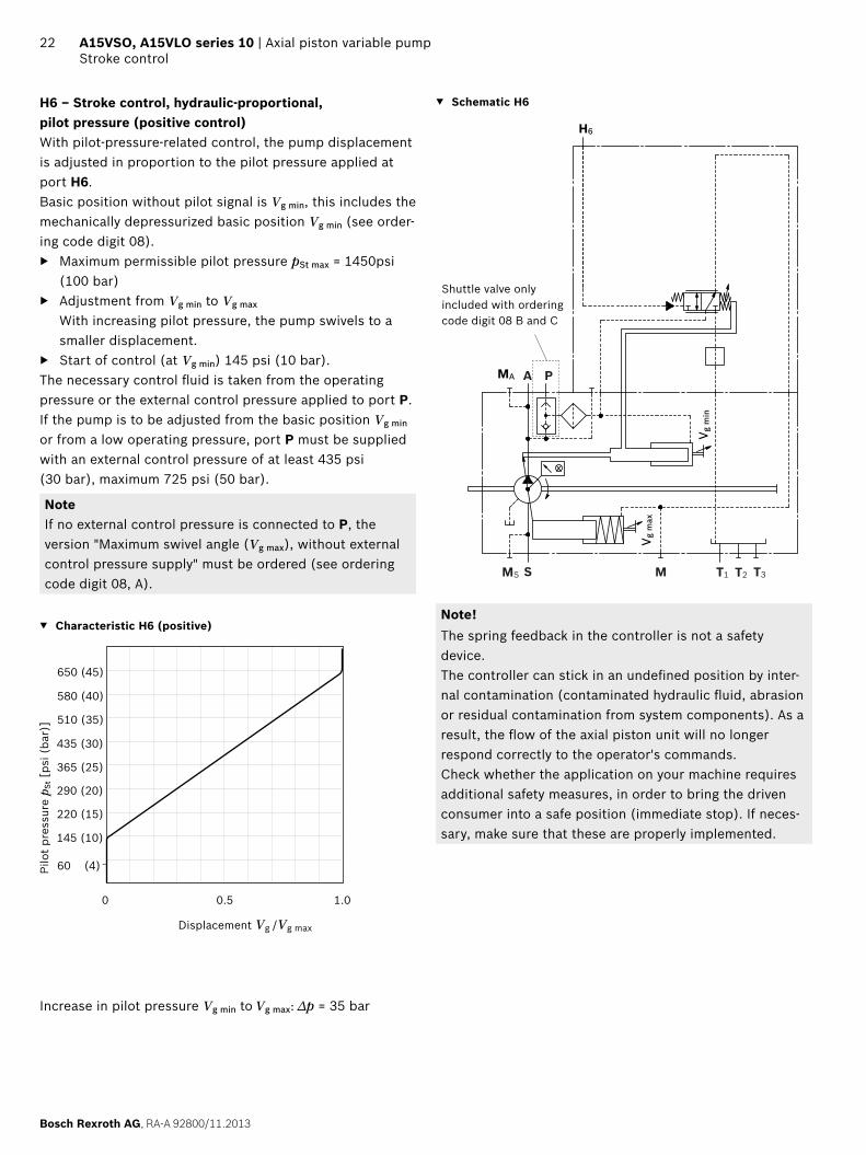
DR – Pressure controller, fi xed setting LRDRS0 – Power controller with pressure controller and load sensing, fi xed setting
4.86
(12
3.5)
9.53 (242)0.
02 (
0.5)
7.09
(18
0.1)
4.70
(11
9.5)
(P)
10.86 (275.9)4.49(114)
P
4.86
(12
3.5)
9.53 (242)
7.36 (187)
0.02
(0.
5)3.
99 (
101.
5)(X
)7.
09 (
180.
1)
4.70
(11
9.5)
(P)
11.64 (295.6)4.49 (114)
PX
DG – Pressure controller, hydraulic, remote controlled DP – Pressure controller, for parallel operation
9.53 (242)7.36 (187)
4.86
(123
.5)
0.02
(0.
5)
4.70
(11
9.5)
(P)
7.09
(18
0.1)
3.99
(10
1.5)
10.86 (275.9)4.49 (114)
PX
5.50
(139
.7)
9.53 (242)
7.09
(18
0.1)
4.31(109.4)
0.98(25)
4.70
(11
9.5)
(P)
P
DP
NoteAll controllers described with shuttle valve in P (some contrary to standard as per ordering code digit 08)

RA-A 92800/11.2013, Bosch Rexroth AG
Axial piston variable pump | A15VSO, A15VLO series 10 Dimensions size 145
31Dimensions [in (mm)]
Dimensions size 145
LRDRS0 – Power controller with pressure controller, load sensing and with electric swivel angle sensorWithout charge pump, clockwise rotation
4.85
(123
.3)
4.49
(114
)
7.34
(18
6.4)
9.92 (252)
1.34 (34)
12.20 (310)
0.19 (4.7)
5.26
(133
.5)
45°
1.25
(31.8
)
2.63(66.7)
2.44
(61.
9)
4.19(106.4)
6.36
(16
1.6)
6.71
(17
0.5)
6.36 (161.6)
7.86
(19
9.6)
7.86 (199.6)
2.94(74.6)
1.18 (30)
0.81
(20.6
)
1.59(40.4)
4.55 (T3)(115.5)
1.97(50)
0.12(3)
5.10 (129.5)
3.88
(98.
6)
5.18(131.5)
45°
0.48
(12.2
)
4.33
(109
.9)
(ø15
2.4
)
6.00
05.
998
DIA
-0.0
5
4.44(112.7)
115.
5
10.54 (267.7) (T3)
8.03 (203.9)
65.5 107.
5
10.10(256.5)
5.06
(128
.5)
6.36
(16
1.6)
4.40(111.7)
(12.7 )0.480.50
-0.5
4.23(107.5)
10.45 (265.5) (P)
W
X
T2MS
S
A
T1 A
T1
MA
M
P
PX
X
MA
S
S
A
Z
T2
T3
T3
0.37
(9.
3)1)
6.22(158.1)1)
6.31)
MS
0.87(22)
Detail X
Detail W
Detail Z
Flange D4SAE J744
1) Center of gravity

Bosch Rexroth AG, RA-A 92800/11.2013
32 A15VSO, A15VLO series 10 | Axial piston variable pumpDimensions size 145
Dimensions [in (mm)]
Splined shaft SAE J744 Parallel keyed shaft DIN 6885
T1 ‒ 1 3/4 in 13T 8/16 DP1) B2 ‒ Ø 50 A 14x9x80
2.64 (67)
2.95 (75)
1.26(32)
2.09 (53)
1/2-
13U
NC
-2B
2) 4
)
2.36
(ø60
)
0.39(10)
DIA
5.1
9 (ø
132)
M16
3)4)
3.54 (90)
DIA
2.36
(ø60
)
1.42(36)
2.11
(53.
5)1.
969
1.96
8DI
A
DIA
5.51
(Ø14
0) (ø50
+0.0
18)
3.23 (82)
0.47(12)
+0.0
02
Ports Standard Size4) pmax abs [psi (bar)]5) Condition9)
A Service line portFastening threads
SAE J5186)
ASME B1.11 1/4 in1/2-13UNC-2B; (depth on request)
6100 (420) O
S Suction port (Without charge pump)Fastening threads
SAE J5186)
ASME B1.13 in5/8-11UNC-2B; (depth on request)
435 (30) O
T1 Drain port ISO 119267) 1 5/16UNF-2B; 0.79 (20) deep 145 (10) O8)
T2 Drain port ISO 119267) 1 5/16UNF-2B; 0.79 (20) deep 145 (10) X8)
T3 Drain port ISO 119267) 1 5/16UNF-2B; 0.79 (20) deep 145 (10) X8)
CR Pilot signal (only on CR) ISO 11926 9/16-18UNF-2B; 0.51 (13) deep 6100 (420) O
PR Pilot signal (only for PR) ISO 11926 9/16-18UNF-2B; 0.51 (13) deep 6100 (420) O
H3 to H6 Pilot signal (only for H3, H4, H5 and H6) ISO 11926 9/16-18UNF-2B; 0.51 (13) deep 1450 (100) O
DP, DP1 Pilot pressure (only on DP) ISO 11926 9/16-18UNF-2B; 0.51 (13) deep 6100 (420) O
X Pilot signal ISO 119267) 9/16-18UNF-2B; 0.51 (13) deep 6100 (420) O
M Control pressure measurement ISO 119267) 9/16-18UNF-2B; 0.51 (13) deep 6100 (420) X
MA Measuring pressure A ISO 119267) 9/16-18UNF-2B; 0.51 (13) deep 6100 (420) X
MS Measuring suction pressure ISO 119267) 9/16-18UNF-2B; 0.51 (13) deep 435 (30) X
P External control pressure (ordering code position 8 version B or C = with external control pressure supply)
ISO 119267) 9/16-18UNF-2B; 0.51 (13) deep 725 (50) O
Port P has no function(ordering code position 8 version A = without external control pressure supply)
ISO 119267) 3/4-16UNF-2B; 0.50 (12.6) deep 6100 (420) X
Key width0.55 (14)
1) Involute spline according to ANSI B92.1a, 30° pressure angle, fl at root, side fi t, tolerance class 5
2) Thread according to ASME B1.13) Center bore according to DIN 332 (thread according to DIN 13)4) Observe the general instructions on page 58 for the maximum
tightening torques.5) Momentary pressure spikes may occur depending on the application.
Keep this in mind when selecting measuring devices and fi ttings.
6) Metric fastening thread according to SAE J518 on request.7) The spot face can be deeper than specifi ed in the appropriate
standard.8) Depending on the installation position, T1, T2 or T3 must be con-
nected (see also installation instructions on pages 55 and 56).
9) O = Must be connected (plugged on delivery) X = Plugged (in normal operation)

RA-A 92800/11.2013, Bosch Rexroth AG
Axial piston variable pump | A15VSO, A15VLO series 10 Dimensions size 145
33Dimensions [in (mm)]
LR – Power controller, fi xed setting L4 – Power controller, electric-proportional override
5.12
(13
0)(P
)10.45 (265.5)0.
22 (
5.5)
7.34
(18
6.4)
12.30 (312.5)5.15 (130.9)
P
7.34
(18
6.4)
0.22
(5.
5)5.
12 (
130)
(P)10.45 (265.5)
2.30 (58.5)12.30 (312.5)
P
CR – Power controller, hydraulic-proportional override, high pressure, with stop
PR – Power controller, hydraulic-proportional override, high pressure, without stop
5.12
(13
0)(P
)
10.45 (265.5)
0.22
(5.
5)7.
34 (
186.
4)
12.30 (312.5)2.04 (51.9)
2.58
(65
.5)(
CR
)7.
91 (
200.
9)
4.94(125.4)
PCR
6.57
(16
6.8)
7.34
(18
6.4)
0.22
(5.
5)
5.12
(13
0)(P
)
10.45 (265.5)
4.30 (109.3)12.30 (312.5)
2.58
(65
.5)
PR
PR P
E2/E6 – Stroke control electric-proportional H3/4/5/6 – Stroke control, hydraulic-prop., pilot pressure
0.86(21.9)
10.70 (271.9)
7.89
(20
0.4)
0.63
(16
)5.
12 (
130)
(P)
5.33
(13
5.5)
10.45 (265.5) P
1.83 (46.4)
3.68(93.4)
5.41
(137
.4)
0.63
(16
)
5.12
(13
0)(P
)
5.33
(13
5.5)
10.45 (265.5)
11.53 (292.8)
7.89
(20
0.4)
1.61
(41
)
P
H3/4/5/6
NoteAll controllers described with shuttle valve in P (some contrary to standard as per ordering code digit 08)

Bosch Rexroth AG, RA-A 92800/11.2013
34 A15VSO, A15VLO series 10 | Axial piston variable pumpDimensions size 145
Dimensions [in (mm)]
DR – Pressure controller, fi xed setting LRDRS0 – Power controller with pressure controller and load sensing, fi xed setting
5.12
(13
0)(P
)10.45 (265.5)0.
22 (
5.5)
7.34
(18
6.4)
5.10
(12
9.5)
11.53 (292.8)5.15 (130.9)
P
5.12
(13
0)(P
)
10.45 (265.5)8.03 (203.9)
0.22
(5.
5)4.
23 (
107.
5)7.
34 (
186.
4)
12.30 (312.5)5.12 (130.9)
PX
DG – Pressure controller, hydraulic, remote controlled DP – Pressure controller, for parallel operation
6.71
(17
0.4)
7.34
(18
6.4)
8.03 (203.9)11.61 (294.9)
10.45 (265.5)8.03 (203.9)
0.22
(5.
5)4.
23 (
107.
5)(X
)5.
12 (
130)
(P)
X
X P
5.41
(137
.4)
7.89
(20
0.4)
0.99(25.1)
3.82(97.1)
11.53 (292.8)
0.31
(7.
8)3.
35 (
85)(
DP 1)
5.12
(13
0)(P
)5.
33(1
35.5
)
DP
DP1 DP10.45 (265.5) P
NoteAll controllers described with shuttle valve in P (some contrary to standard as per ordering code digit 08)

RA-A 92800/11.2013, Bosch Rexroth AG
Axial piston variable pump | A15VSO, A15VLO series 10 Dimensions size 175
35Dimensions [in (mm)]
Dimensions size 175
LRDRS0 – Power controller with pressure controller, load sensing and with electric swivel angle sensorWithout charge pump, clockwise rotation
5.30
(134
.5)
5.08
(129
)
7.57
(19
2.4)
0.98 (25)
10.61 (269.5)12.89 (327.5)
0.20 (5)
5.59 (
142)
45°
1.25
(31.8
)
2.63(66.7)
2.44
(61.
9)
4.19(106.4)
8.84
(22
4.5)
6.95
(17
6.6)
8.84 (224.5)
10.3
3 (2
62.5
)
10.33 (262.5)
2.91(74)
1.26 (32)
0.81 (
20.6)
1.69(43)
2.09(53)
0.24(6)
5.26(133.7)
4.84 (T3)(123)
4.13
(105
)
5.51(140)
45°
0.51
(13)
4.65
(118
)
(ø16
5.1
)
6.50
06.
498
DIN
-0.0
5
4.63(117.5)
11.12 (282.5) (T3)
8.51 (216.2)
2.74
(69.
7)
4.84
(123
)
10.65 (270.5)
5.51
(140
)6.
81 (
173.
1)
4.69(119)
(15.9 )0.630.60 -0.5
4.40(111.7)
4.40
(111
.7)
T3
W
X
T2 S
A
T1 A
T1
MA
M
P
X
X
MA
T3
S
S
MS
A
Z
T2
0.33
(8.
5)1)
0.22
(5.
6)1)
6.29(159.7)1)
P
11.00 (279.5) (P)MS
1.42 (36)
Detail X
Detail W
Flange E4SAE J744
Detail Z
3/8-16 UNC-2B 0.71 (18) deep Thread for eye bolt (additional thread on underside of case)
1) Center of gravity

Bosch Rexroth AG, RA-A 92800/11.2013
36 A15VSO, A15VLO series 10 | Axial piston variable pumpDimensions size 175
Dimensions [in (mm)]
LRDRS0 – Power controller with pressure controller, load sensing and with electric swivel angle sensorWith charge pump, clockwise rotation
0.98 (25)
12.50 (317.5)
0.16 (4)
5.59 (
142)
45°
1.25 (
31.8)
2.63(66.7)
2.75
(69.
9)
4.75(120.7)
6.95
(17
6.6)
10.3
3 (2
62.5
)
10.33 (262.5)
3.54(90)
1.26 (32)
0.81 (
20.6)
0.87 (22)2.95(75)
0.24 (6)
5.26(133.7)
4.84 (T3)(123)
4.13
(105
)
5.51(140)
45°
0.51
(13)
4.92
(125
)
DIA
-0.0
5
4.63(117.5)
2.74
(6
9.7) 5.00
(127
)
4.40
(111
.7)
10.65 (270.5)
5.35
(13
6)6.
81 (
173.
1)
4.68(119)
4.40(111.7)
14.82 (376.5)15.53 (394.5)
5.29
(134
.5)
5.08
(129
)
7.57
(19
2.4)
8.84
(22
4.5)
8.84 (224.5)
(ø16
5.1
)
6.50
06.
498
W
X
T2
S
A
T1 A
T1
MA
M
P
MA
S
S
A
X
X
P
T2
Z
11.12 (282.5) (T3)
8.51 (216.2)(15.9 )0.600.63
-0.5
11.00 (279.5) (P)
0.27
(6.
8)1)
7.47 (189.8)1)0.
22 (
5.7)
1)
T3
1.42 (36)
Detail X
Detail W
Flange E4SAE J744
Detail Z
1) Center of gravity
3/8-16 UNC-2B 0.71 (18) deep Thread for eye bolt (additional thread on underside of case)

RA-A 92800/11.2013, Bosch Rexroth AG
Axial piston variable pump | A15VSO, A15VLO series 10 Dimensions size 175
37Dimensions [in (mm)]
Splined shaft SAE J744 Parallel keyed shaft DIN 6885
T2 ‒ 2 in 15T 8/16 DP1) B2 ‒ Ø 50 A 14x9x80
3.46 (88)
1.42(36)
2.60 (66)
5/8-
11U
NC
-2B
2) 4
)
2.36
(ø60
)
3.15 (80)
0.47(12)
DIA
5.5
1 (ø
140)
M16
3)4)
3.54 (90)
DIA
2.36
(ø60
)
1.42(36)
2.11
(53.
5)1.
969
1.96
8DI
A
DIA
5.51
(Ø14
0) (ø50
+0.0
18)
3.23 (82)
0.47(12)
+0.0
02
Ports Standard Size4) pmax abs [psi (bar)]5) Condition9)
A Service line portFastening threads
SAE J5186)
ASME B1.11 1/4 in1/2-13UNC-2B; (depth on request)
6100 (420) O
S Suction port (Without charge pump)Fastening threads
SAE J5186)
ASME B1.13 in5/8-11UNC-2B; (depth on request)
435 (30) O
S Suction port (with charge pump)Fastening threads
SAE J5186)
ASME B1.13 1/2 in5/8-11UNC-2B; (depth on request)
30 (2) OO
T1 Drain port ISO 119267) 1 5/16UNF-2B; 0.79 (20) deep 145 (10) O8)
T2 Drain port ISO 119267) 1 5/16UNF-2B; 0.79 (20) deep 145 (10) X8)
T3 Drain port ISO 119267) 1 5/16UNF-2B; 0.79 (20) deepp 145 (10) X8)
CR Pilot signal (only on CR) ISO 11926 9/16-18UNF-2B; 0.51 (13) deep 6100 (420) O
PR Pilot signal (only for PR) ISO 11926 9/16-18UNF-2B; 0.51 (13) deep 6100 (420) O
H3 to H6 Pilot signal (only for H3, H4, H5 and H6) ISO 11926 9/16-18UNF-2B; 0.51 (13) deep 1450 (100) O
DP, DP1 Pilot pressure (only on DP) ISO 11926 9/16-18UNF-2B; 0.51 (13) deep 6100 (420) O
X Pilot signal ISO 119267) 9/16-18UNF-2B; 0.51 (13) deep 6100 (420) O
M Control pressure measurement ISO 119267) 9/16-18UNF-2B; 0.51 (13) deep 6100 (420) X
MA Measuring pressure A ISO 119267) 9/16-18UNF-2B; 0.51 (13) deep 6100 (420) X
MS Measuring suction pressure ISO 119267) 9/16-18UNF-2B; 0.51 (13) deep 435 (30) X
P External control pressure (ordering code position 8 version B or C = with external control pressure supply)
ISO 119267) 9/16-18UNF-2B; 0.51 (13) deep 725 (50) O
Port P has no function(ordering code position 8 version A = without external control pressure supply)
ISO 119267) 3/4-16UNF-2B; 0.50 (12.6) deep 6100 (420) X
Key width0.55 (14)
1) Involute spline according to ANSI B92.1a, 30° pressure angle, fl at root, side fi t, tolerance class 5
2) Thread according to ASME B1.13) Center bore according to DIN 332 (thread according to DIN 13)4) Observe the general instructions on page 58 for the maximum
tightening torques.5) Momentary pressure spikes may occur depending on the application.
Keep this in mind when selecting measuring devices and fi ttings.
6) Metric fastening thread according to SAE J518 on request.7) The spot face can be deeper than specifi ed in the appropriate
standard.8) Depending on the installation position, T1, T2 or T3 must be con-
nected (see also installation instructions on pages 55 and 56).
9) O = Must be connected (plugged on delivery) X = Plugged (in normal operation)

Bosch Rexroth AG, RA-A 92800/11.2013
38 A15VSO, A15VLO series 10 | Axial piston variable pumpDimensions size 175
Dimensions [in (mm)]
LR – Power controller, fi xed setting L4 – Power controller, electric-proportional override
0.38
(9.
7)7.
57 (
192.
4)
5.65
(14
3.5)
11.00 (279.5)
5.29
(13
4.5)
(P)P
5.64 (143.2)12.79 (324.8)
7.57
(19
2.4)
2.79(70.8)
12.79 (324.8)
0.38
(9.
7)5.
29 (
134.
5)(P
)11.00 (279.5)P
5.65
(14
3.5)
CR – Power controller, hydraulic-proportional override, high pressure, with stop
PR – Power controller, hydraulic-proportional override, high pressure, without stop
0.38
(9.
7)7.
57 (
192.
4)
5.42 (137.7)
2.74
(69
.7)(
CR
)8.
15 (
207)
11.00 (279.5)
PCR
2.53(64.2)
12.79 (324.8)
5.65
(14
3.5)
5.29
(13
4.5)
(P)
6.81
(17
2.9)
7.57
(19
2.4)
4.79(121.6)
12.79 (324.8)
0.38
(9.
7)
5.29
(13
4.5)
(P)
5.26
(13
3.7)
11.00 (279.5)
2.74
(69
.7)(
PR)
PR
PR P
5.65
(14
3.5)
E2/E6 – Stroke control electric-proportional H3/4/5/6 – Stroke control, hydraulic-prop., pilot pressure
0.79
(20
.2)
5.29
(13
4.5)
(P)
5.50
(13
9.7)
8.13
(20
6.5)
11.00 (279.5) P
1.35 (34.2)11.19 (284.2)
5.65
(14
3.5)
1.78
(45
.2)
5.29
(13
4.5)
(P)
5.50
(13
9.7)
5.65
(143
.5)
11.00 (279.5)
0.79
(20
.2)
8.13
(20
6.5)
P
H3/4/5/64.16(105.7)
11.07 (281.1)
2.31(58.7)
5.65
(14
3.5)
NoteAll controllers described with shuttle valve in P (some contrary to standard as per ordering code digit 08)
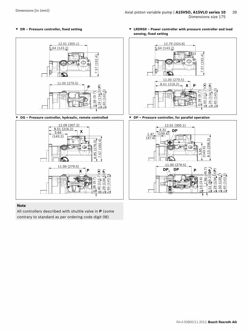
RA-A 92800/11.2013, Bosch Rexroth AG
Axial piston variable pump | A15VSO, A15VLO series 10 Dimensions size 175
39Dimensions [in (mm)]
DR – Pressure controller, fi xed setting LRDRS0 – Power controller with pressure controller and load sensing, fi xed setting
0.38
(9.
7)7.
57 (
192.
4)5.
29 (
134.
5)(P
)11.00 (279.5)P
5.64 (143.2)12.01 (305.1)
5.65
(14
3.5)
0.38
(9.
7)
5.65
(14
3.5)
7.57
(19
2.4)
5.29
(13
4.5)
(P)
11.00 (279.5)8.51 (216.2)
4.40
(11
1.7)
(X)
PX
5.64 (143.2)12.79 (324.8)
DG – Pressure controller, hydraulic, remote controlled DP – Pressure controller, for parallel operation
6.95
(17
6.5)
7.57
(19
2.4)
8.51 (216.2)5.64
(143.2)
12.09 (307.2)
11.00 (279.5)
0.38
(9.
7)4.
40 (
111.
7)(X
)5.
29 (
134.
5)(P
)
X
X P
5.65
(14
3.5)
1.96
(49
.7)
0.14
(3.
6)
5.50
(13
9.7)
3.51
(89
.2)(
DP 1)
5.65
(143
.5)
8.13
(20
6.5)
4.31 (109.4)1.47
(37.4)
DP
DP PDP1
5.65
(14
3.5)
11.00 (279.5)
12.01 (305.1)
5.2
9 (1
34.5
)(P)
NoteAll controllers described with shuttle valve in P (some contrary to standard as per ordering code digit 08)

Bosch Rexroth AG, RA-A 92800/11.2013
40 A15VSO, A15VLO series 10 | Axial piston variable pumpDimensions size 210
Dimensions [in (mm)]
Dimensions size 210
LRDRS0 – Power controller with pressure controller, load sensing and with electric swivel angle sensorWithout charge pump, clockwise rotation
7.26
(18
4.3)
10.3
3 (2
62.5
)
5.41
(137
.3)
5.12
(130
)
7.88
(20
0.2)
1.02 (25.8)
11.12 (282.5)13.57 (344.8)
0.31 (8)
5.98 (
152)
45°
1.44
(36.5
)
3.13(79.4)
2.75
(69.
9)
4.75(120.7)
10.33 (262.5)
3.54(90)
1.50 (38)
0.81 (
20.6)
1.77(45)
56
5.43(138)
5.20 (T3)(132)
4.29
(109
)
5.83(148)
45°
0.71
(18)
5.04
(128
)
DIA
-0.0
5
4.72(120)
5.00
(127
)
11.80 (299.6) (T3)
9.08 (230.7)
2.91
(74) 4.
57(1
16)
11.24 (285.6)
5.73
(145
.5)
7.03
(17
8.6)
5.08(129)
(15.9 )0.630.61 -0.5
0
0.18 (4.5)
11.56 (293.6) (P)8.
84 (
224.
5)
8.84 (224.5)
(ø16
5.1
)
6.50
06.
498
W
X
T2
S
A
T1A
T1
MA
MSM
P
T3
X
X
MA
S
S
Z
T2
A
T3
1.71(43.5)
4.57(116)
0.31
(7.
8)1)
6.76(171.7)1)
0.20
(5)
1)
P
MS
Detail X
Detail W
Flange E4SAE J744
Detail Z1/1-13 UNC-2B; 0.87 (22) deep Thread for eye bolt (additional thread on underside of case)
1) Center of gravity

RA-A 92800/11.2013, Bosch Rexroth AG
Axial piston variable pump | A15VSO, A15VLO series 10 Dimensions size 210
41Dimensions [in (mm)]
LRDRS0 – Power controller with pressure controller, load sensing and with electric swivel angle sensorWith charge pump, clockwise rotation
Detail X
Detail W
Flange E4SAE J744
Detail Z
1/1-13 UNC-2B; 0.87 (22) deep Thread for eye bolt (additionalthread on underside of case)
13.14 (333.8)
7
5.91 (
150)
45°
1.44
(36.5
)
3.12(79.4)
2.75
(69.
9)
4.75(120.7)
7.26
(18
4.3)
10.3
3 (2
62.5
)
10.33 (262.5)
3.54(90)
1.50 (38)
0.81 (
20.6)
0.63(16)
3.15(80)
5.43 (138)
5.20 (T3)(132)
4.29
(109
)
5.83(148)
45°
0.71
(18)
5.31
(135
)
-0.0
5
4.80(122)
132
74 116
11.24 (285.6)
5.61
(142
.5)
7.03
(17
8.6)
4.92(125)
(15.9 )0.630.61 -0.5
0
0.18 (4.5)
15.50 (393.8)16.21 (411.8)
4.57 (116)
0.27
(6.
9)1)
299.6 (T3)
9.08 (230.7)11.53 (292.8) (P)
1.02 (25.8)
5.40
(137
.3)
5.12
(130
)
7.88
(20
0.2)
8.84
(22
4.5)
8.84 (224.5)
(ø16
5.1
)
6.50
06.
498
DIA
W
X
T2 S
A
T1 A
T1
MA
M
P
X
X
MA
S
S
A
T3
P
T3
Z
4.31)
7.68 (195)1)T2
1.71 (43.5)
1) Center of gravity

Bosch Rexroth AG, RA-A 92800/11.2013
42 A15VSO, A15VLO series 10 | Axial piston variable pumpDimensions size 210
Dimensions [in (mm)]
Splined shaft SAE J744 Parallel keyed shaft DIN 5480
T2 ‒ 2 in 15T 8/16 DP1) B2 ‒ Ø 50 A 14x9x80
3.46 (88)
1.42(36)
2.60 (66)
5/8-
11U
NC
-2B
2) 4
)
2.36
(ø60
)
3.15 (80)
0.47(12)
DIA
5.5
1 (ø
140)
M16
3)4)
3.54 (90)
DIA
2.36
(ø60
)
1.42(36)
2.11
(53.
5)1.
969
1.96
8DI
A
DIA
5.51
(Ø14
0) (ø50
+0.0
18)
3.23 (82)
0.47(12)
+0.0
02
Ports Standard Size4) pmax abs [psi (bar)]5) Condition9)
A Service line portFastening threads
SAE J5186)
ASME B1.11 1/2 in5/8-11UNC-2B; 30 deep
6100 (420) O
S Suction port (Without charge pump)Fastening threads
SAE J5186)
ASME B1.13 1/2 in5/8-11UNC-2B; 30 deep
435 (30) O
S Suction port (with charge pump)Fastening threads
SAE J5186)
ASME B1.13 1/2 in5/8-11UNC-2B; 30 deep
30 (2) O
T1 Drain port ISO 119267) 1 5/8-12UN-2B; 0.79 (20) deep 145 (10) O8)
T2 Drain port ISO 119267) 1 5/8-12UN-2B; 0.79 (20) deep 145 (10) X8)
T3 Drain port ISO 119267) 1 5/8-12UN-2B; 0.79 (20) deep 145 (10) X8)
CR Pilot signal (only on CR) ISO 11926 9/16-18UNF-2B; 0.51 (13) deep 6100 (420) O
PR Pilot signal (only for PR) ISO 11926 9/16-18UNF-2B; 0.51 (13) deep 6100 (420) O
H3 to H6 Pilot signal (only for H3, H4, H5 and H6) ISO 11926 9/16-18UNF-2B; 0.51 (13) deep 1450 (100) O
DP, DP1 Pilot pressure (only on DP) ISO 11926 9/16-18UNF-2B; 0.51 (13) deep 6100 (420) O
X Pilot signal ISO 119267) 9/16-18UNF-2B; 0.51 (13) deep 6100 (420) O
M Control pressure measurement ISO 119267) 9/16-18UNF-2B; 0.51 (13) deep 6100 (420) X
MA Measuring pressure A ISO 119267) 9/16-18UNF-2B; 0.51 (13) deep 6100 (420) X
MS Measuring suction pressure ISO 119267) 9/16-18UNF-2B; 0.51 (13) deep 435 (30) X
P External control pressure (ordering code position 8 version B or C = with external control pressure supply)
ISO 119267) 9/16-18UNF-2B; 0.51 (13) deep 725 (50) O
Port P has no function(ordering code position 8 version A = without external control pressure supply)
ISO 119267) 3/4-16UNF-2B; 0.50 (12.6) deep 6100 (420) X
Key width0.55 (14)
1) Involute spline according to ANSI B92.1a, 30° pressure angle, fl at root, side fi t, tolerance class 5
2) Thread according to ASME B1.13) Center bore according to DIN 332 (thread according to DIN 13)4) Observe the general instructions on page 58 for the maximum
tightening torques.5) Momentary pressure spikes may occur depending on the application.
Keep this in mind when selecting measuring devices and fi ttings.
6) Metric fastening thread according to SAE J518 on request.7) The spot face can be deeper than specifi ed in the appropriate
standard.8) Depending on the installation position, T1, T2 or T3 must be con-
nected (see also installation instructions on pages 55 and 56).
9) O = Must be connected (plugged on delivery) X = Plugged (in normal operation)

RA-A 92800/11.2013, Bosch Rexroth AG
Axial piston variable pump | A15VSO, A15VLO series 10 Dimensions size 210
43Dimensions [in (mm)]
LR – Power controller, fi xed setting L4 – Power controller, electric-proportional override
0.55
(14
)7.
88 (
200.
2)5.
35 (
136)
(P)
11.56 (293.6)
5.43
(13
8)5.
87 (
149)
P
6.21(157.7)
13.36 (339.3)
7.88
(20
0.2)
3.36(85.3)
13.36 (339.3)
0.55
(14
)5.
35 (
136)
(P)
5.43
(13
8)5.
87 (
149)
11.56 (293.6)P
CR – Power controller, hydraulic-proportional override, high pressure, with stop
PR – Power controller, hydraulic-proportional override, high pressure, without stop
0.55
(14
)7.
88 (
200.
2)
5.35
(13
6)(P
)
5.99(152.2)
5.43
(13
8)5.
87 (
149)
2.91
(74
)(C
R)
8.45
(21
4.7)
11.56 (293.6)
PCR
3.10(78.7)
13.36 (339.3)
7.11
(18
0.6)
7.88
(20
0.2)
5.36(136.1)
13.36 (339.3)
0.55
(14
)2.
91 (
74)
5.35
(13
6)(P
)5.
43 (
138)
5.87
(14
9)
11.56 (293.6)
PR
PR P
E2/E6 – Stroke control electric-proportional H3/4/5/6 – Stroke control, hydraulic-prop., pilot pressure
0.96
(24
.5)
5.35
(13
6)(P
)5.
67 (
144)
5.87
(14
9)
8.43
(21
4.2)
11.56 (293.6) P
1.92(48.7)
11.75 (298.6)
1.93
(49
)(H
x)5.
35 (
136)
(P)
5.67
(14
4)5.
87 (
149)
11.56 (293.6)
0.96
(24
.5)
5.95
(151
.2)
8.43
(21
4.2)
P
H3/4/5/64.73
(120.2)
11.64 (295.6)
2.88(73.2)
NoteAll controllers described with shuttle valve in P (some contrary to standard as per ordering code digit 08)

Bosch Rexroth AG, RA-A 92800/11.2013
44 A15VSO, A15VLO series 10 | Axial piston variable pumpDimensions size 210
Dimensions [in (mm)]
DR – Pressure controller, fi xed setting LRDRS0 – Power controller with pressure controller and load sensing, fi xed setting
0.55
(14
)7.
88 (
200.
2)5.
35 (
136)
(P)
11.56 (293.6)
5.43
(13
8)5.
87 (
149)
P
6.21(157.7)
12.58 (319.6)
0.55
(14
)7.
88 (
200.
2)
5.35
(13
6)(P
)
11.56 (293.6)9.08 (230.7)
4.57
(11
6)(X
)
5.43
(13
8)5.
87 (
149)
PX
6.21(157.7)
13.36 (339.3)
DG – Pressure controller, hydraulic, remote controlled DP – Pressure controller, for parallel operation
7.25
(18
4.2)
7.88
(20
0.2)
6.21(157.7)
12.66 (321.7)
11.56 (293.6)9.08 (230.7)
0.55
(14
)4.
57 (
116)
(X)
5.35
(13
6)(P
)5.
43 (
138)
5.87
(14
9)
X
X P
5.35
(13
6)(P
)
11.56 (293.6)P
5.95
(151
.2)
8.43
(21
4.2)2.04 (51.9)
4.88 (123.9)11.64 (295.6)
0.03
(0.
7)2.
13 (
54)
5.67
(14
4)5.
87 (
149)
DP
DP
NoteAll controllers described with shuttle valve in P (some contrary to standard as per ordering code digit 08)

RA-A 92800/11.2013, Bosch Rexroth AG
Axial piston variable pump | A15VSO, A15VLO series 10 Dimensions size 280
45Dimensions [in (mm)]
Dimensions size 280
LRDRS0 – Power controller with pressure controller, load sensing and with electric swivel angle sensorWithout charge pump, clockwise rotation
T3
P
A
0.26
(6.
5)1)
7.71(195.8)1)
0.17
(4.
2)1)
6.16
(156
.4)
5.43
(138
)
8.20
(20
8.3)
1.34 (34)
1.69 (43)
12.76 (324)
15.24 (387)
0.39 (10)
6.50 (
165)
45°
1.44
(36.5
)
3.13(79.4)
2.75
(69.
9)
4.75(120.7)
7.57
(19
2.4)
10.3
3 (2
62.5
)
10.33 (262.5)
3.54(90)
1.50 (38)
0.81 (
20.6)
1.97(50)
2.44(62)
0.20(5)
5.67(144)
5.51 (T3)(140)
4.76
(121
)
6.38(162)
45°
0.59
(15)
5.31
(135
)
DIA
-0.0
5
5.51(140)
5.51
(140
)
13.07 (332) (T3)
10.29 (261.4)
3.15
(80) 4.80
(122
)
12.48 (317)
6.08
(154
.5)
7.39
(18
7.6)
5.59(142)
12.95 (329) (P)
8.84
(22
4.5)
8.84 (224.5)
(ø16
5.1
)
6.50
06.
498
W
X
T2
S
A
T1 A
T1
MA
M
P
MS
T3
X
X
MA
S
S
Z
T2
4.80(122)
MS
(15.9 )0.630.61 -0.5
0
Detail X
Flange E4SAE J744
Detail W
Detail Z
1/1-13 UNC-2B; 0.87 (22) deep Thread for eye bolt (additional thread on underside of case)
1) Center of gravity

Bosch Rexroth AG, RA-A 92800/11.2013
46 A15VSO, A15VLO series 10 | Axial piston variable pumpDimensions size 280
Dimensions [in (mm)]
LRDRS0 – Power controller with pressure controller, load sensing and with electric swivel angle sensorWith charge pump, clockwise rotation
Z
T2
A
P
T3
T3
6.16
(156
.4)
5.43
(138
)
8.20
(20
8.3)
10.29 (261.4)
1.69 (43)
1.34 (34)
14.13 (359)
0.39 (10)
6.50 (
165)
45°
1.44 (
36.5)
3.13(79.4)
3.06
(77.
8)
130.2
10.33 (262.5)
3.94(100)
1.50 (38)
0.81 (
20.6)
0.71(18)
3.54(90)
0.20 (5)
5.67 (144)
4.76
(121
)
6.38 (162)
45°
0.59
(15)
5.67
(14
4)
5.51(140)
5.71
(14
5)
3.15
(80) 4.
80(1
22)
12.48 (317)
5.90
(150
)7.
38 (
187.
6)
5.59 (142)
16.73 (425)17.44 (443)
4.80(122)
13.07 (332) (T3)
12.95 (329) (P)
7.57
(19
2.4)
10.3
3 (2
62.5
)(15.9 )
0.630.61 -0.5
0
-0.0
5
8.84
(22
4.5)
8.84 (224.5)
(ø16
5.1
)
6.50
06.
498
DIA
W
T2S
A
T1 A
T1
MA
M
P
X
X
MA
S
S
0.15
(3.
8)1)
9.25 (235)1)
0.13
(3.
2)1)
5.51 (140) (T3)
X
1) Center of gravity
Detail X
Flange E4SAE J744
Detail W
Detail Z
1/1-13 UNC-2B; 0.87 (22) deep Thread for eye bolt (additional thread on underside of case)
RA-A 92800/11.2013, Bosch Rexroth AG
Axial piston variable pump | A15VSO, A15VLO series 10 Dimensions size 280
47Dimensions [in (mm)]
Splined shaft SAE J744 Parallel keyed shaft DIN 6885
T3 ‒ 2 1/4 in 17T 8/16 DP1) B4 ‒ Ø 60 A 18x11x100
3.46 (87.9)
1.65(42)
2.60 (66)
3/4-
10U
NC
-2B
2) 4
)
2.76
(ø70
)
3.15 (80)
0.59(15)
DIA
5.5
1 (ø
140)
DIA
5.51
(ø14
0)
M20
x 2
.51)
2)
4.44 (112.9)
DIA
2.76
(ø70
)
0.59(15)
1.65 (42)
2.52
(64)
2.36
32.
362
DIA
ø60
+0.0
30
4.13 (105)
+0.0
11
Ports Standard Size4) pmax abs [psi (bar)]5) Condition9)
A Service line portFastening threads
SAE J5186)
ASME B1.11 1/2 in5/8-11UNC-2B; 35 deep
6100 (420) O
S Suction port (Without charge pump)Fastening threads
SAE J5186)
ASME B1.13 1/2 in5/8-11UNC-2B; 35 deep
435 (30) O
S Suction port (with charge pump)Fastening threads
SAE J5186)
ASME B1.14 in5/8-11UNC-2B; 35 deep
30 (2) O
T1 Drain port ISO 119267) 1 5/8-12UN-2B; 0.79 (20) deep 145 (10) O8)
T2 Drain port ISO 119267) 1 5/8-12UN-2B; 0.79 (20) deep 145 (10) X8)
T3 Drain port ISO 119267) 1 5/8-12UN-2B; 0.79 (20) deep 145 (10) X8)
CR Pilot signal (only on CR) ISO 11926 9/16-18UNF-2B; 0.51 (13) deep 6100 (420) O
PR Pilot signal (only for PR) ISO 11926 9/16-18UNF-2B; 0.51 (13) deep 6100 (420) O
H3 to H6 Pilot signal (only for H3, H4, H5 and H6) ISO 11926 9/16-18UNF-2B; 0.51 (13) deep 1450 (100) O
DP, DP1 Pilot pressure (only on DP) ISO 11926 9/16-18UNF-2B; 0.51 (13) deep 6100 (420) O
X Pilot signal ISO 119267) 9/16-18UNF-2B; 0.51 (13) deep 6100 (420) O
M Control pressure measurement ISO 119267) 9/16-18UNF-2B; 0.51 (13) deep 6100 (420) X
MA Measuring pressure A ISO 119267) 9/16-18UNF-2B; 0.51 (13) deep 6100 (420) X
MS Measuring suction pressure ISO 119267) 9/16-18UNF-2B; 0.51 (13) deep 435 (30) X
P External control pressure (ordering code position 8 version B or C = with external control pressure supply)
ISO 119267) 9/16-18UNF-2B; 0.51 (13) deep 725 (50) O
Port P has no function(ordering code position 8 version A = without external control pressure supply)
ISO 119267) 3/4-16UNF-2B; 0.50 (12.6) deep 6100 (420) X
Key width0.71 (18)
1) Involute spline according to ANSI B92.1a, 30° pressure angle, fl at root, side fi t, tolerance class 5
2) Thread according to ASME B1.13) Center bore according to DIN 332 (thread according to DIN 13)4) Observe the general instructions on page 58 for the maximum
tightening torques.5) Momentary pressure spikes may occur depending on the application.
Keep this in mind when selecting measuring devices and fi ttings.
6) Metric fastening thread according to SAE J518 on request.7) The spot face can be deeper than specifi ed in the appropriate
standard.8) Depending on the installation position, T1, T2 or T3 must be con-
nected (see also installation instructions on pages 55 and 56).
9) O = Must be connected (plugged on delivery) X = Plugged (in normal operation)

Bosch Rexroth AG, RA-A 92800/11.2013
48 A15VSO, A15VLO series 10 | Axial piston variable pumpDimensions size 280
Dimensions [in (mm)]
LR – Power controller, fi xed setting L4 – Power controller, electric-proportional override
5.73
(14
5.5)
(P)
8.20
(20
8.3)
7.42(188.4)
5.77
(14
6.5)
12.95 (329)0.
79 (
20)
14.57 (370)
P
6.22
(15
8)
5.67
(14
4)(P
)
8.20
(20
8.3)
4.57(116)
5.73
(14
5.5)
12.95 (329)
0.79
(20
)
14.57 (370)
P
CR – Power controller, hydraulic-proportional override, high pressure, with stop
PR – Power controller, hydraulic-proportional override, high pressure, without stop
3.15
(80
)(C
R)
5.73
(14
5.5)
PCR
8.77
(22
2.8)
4.31(109.4)
5.77
(14
6.5)
(P)
12.95 (329)
0.79
(20
)
14.57 (370)
7.20(182.9)
6.22
(15
8)
6.57(166.8)
14.57 (370)
12.95 (329)
0.79
(20
)
5.73
(14
5.5)
(P)
3.15
(80
)
PR
PPR
8.20
(20
8.3)
7.43
(18
8.7)
6.22
(15
8) E2/E6 – Stroke control electric-proportional H3/4/5/6 – Stroke control, hydraulic-prop., pilot pressure
8.75
(22
2.3)
12.97 (329.4)
3.13(79.4)
P
5.91
(15
0)
12.95 (329)
1.20
(30
.5)
5.73
(14
5.5)
(P)
6.22
(15
8)
8.75
(222
.3)
5.94(150.9)4.11
(104.4)
12.97 (329.4)
6.27
(159
.3)
H3/4/5/6
P
5.91
(15
0)5.
73 (
145.
5)(P
)329
1.20
(30
.5)
2.19
(55
.5)
6.22
(15
8)
NoteAll controllers described with shuttle valve in P (some contrary to standard as per ordering code digit 08)

RA-A 92800/11.2013, Bosch Rexroth AG
Axial piston variable pump | A15VSO, A15VLO series 10 Dimensions size 280
49Dimensions [in (mm)]
DR – Pressure controller, fi xed setting LRDRS0 – Power controller with pressure controller and load sensing, fi xed setting
5.73
(14
5.5)
(P)
8.20
(20
8.3)
7.42 (188.4)
5.77
(14
6.5)
12.95 (329)0.
79 (
20)
13.79 (350.3)
P
6.22
(15
8)
5.73
(14
5.5)
(P)
4.80
(12
2)(X
)20
8.3
7.42 (188.4)
5.77
(14
6.5)
12.95 (329)10.29 (261.4)
0.79
(20
)
14.57 (370)
PX
6.22
(15
8)
DG – Pressure controller, hydraulic, remote controlled DP – Pressure controller, for parallel operation
7.57
(19
2.3)
8.20
(20
8.3)
7.42(188.4)
10.29 (261.4)(352.4)
0.79
(20
)4.
80 (
122)
(X)
5.73
(14
5.5)
(P)12.95 (329)
X
X P
6.22
(15
8)
DP
DP1 DP
0.26
(6.
7)2.
36 (
60)(
DP)
3.92
(99
.5)(
DP 1
)
5.91
(15
0)
6.27
(159
.3)
8.75
(22
2.3)3.25
(82.6)
6.09(154.6)
13.79 (350.3)
6.22
(15
8)
5.73
(14
5.5)
(P)
12.95 (329)
P
NoteAll controllers described with shuttle valve in P (some contrary to standard as per ordering code digit 08)

Bosch Rexroth AG, RA-A 92800/11.2013
50 A15VSO, A15VLO series 10 | Axial piston variable pumpThrough drive dimensions
Dimensions [in (mm)]
Through drive dimensions
Flange SAE J744 Hub for splined shaft2) Availability over sizes Short codeDiameter Attachment1) Designation Diameter Designation 110 145 175 210 280
82-2 (A) A3 3/4 in 11T 16/32DP S3 A3S3
101-2 (B) B3 7/8 in 13T 16/32DP S4 B3S4
1 in 15T 16/32DP S5 B3S5101-2 (B) B5 7/8 in 13T 16/32DP S4 B5S4
1 in 15T 16/32DP S5 B5S5
= Available = On request
82-2 (A) 101-2 (B)
ø82.
55
DIA
3.25
23.
251
+0.0
5+0
.02
M2
0.27(7)4.19
(106.4)A1A2
M1 (to mounting fl ange)
O-ring4)M10; 0.59 (15) deep3) M12; 18 deep3)
(ø10
1.6
)
DIA
4.00
24.
001
+0.0
5+0
.02
M2
0.43(11)
5.75(146)
5.75
(146
)
B3B5
B3 B5
M1 (to mounting fl ange)
O-ring4)
A3S3 NG M1 M2 B3S4, B3S5 NG M1 M2
without charge pump 175 13.41(340.5)
1.33(33.8)
Without charge pump 175 13.96(354.5)
1.69(43)
210 14.09(357.8)
1.33(33.8)
210 14.64(371.8)
1.69(43)
280 15.75(400)
1.33(33.8)
280 16.30(414)
1.69(43)
with charge pump 175 15.33(389.5)
1.33(33.8)
With charge pump 175 15.88(403.5)
1.69(43)
210 16.02(406.8)
1.33(33.8)
210 16.57(420.8)
1.69(43)
280 17.24(438)
1.33(33.8)
280 17.79(452)
1.69(43)
1) Mounting hole pattern viewed on through drive face with control at top
2) According to ANSI B92.1a, 30° pressure angle, fl at root, side fi t, tolerance class 5
3) Thread according to DIN 13, observe the general instructions on page 58 for the maximum tightening torques.
4) O-ring included in the scope of supply

RA-A 92800/11.2013, Bosch Rexroth AG
Axial piston variable pump | A15VSO, A15VLO series 10 Through drive dimensions
51Dimensions [in (mm)]
Flange SAE J744 Hub for splined shaft2) Availability over sizes Short codeDiameter Attachment1) Designation Diameter Designation 110 145 175 210 280
127-2 (C) C3 1 1/4 in 14T 12/24DP S7 C3S7
1 1/2 in 17T 12/24DP S9 C3S9
152-4 (D) D4 1 3/4 in 13T 8/16DP T1 D4T1
165-4 (E) E4 2 in 15T 8/16DP T2 E4T2
2 1/4 in 17T 8/16DP T3 E4T3
= Available = On request
127-2 (C) 152-4 (D)
(ø12
7
)D
IA5.
002
5.00
1+0
.05
+0.0
2
M2
0.55(14)
7.13(181)
7.13
(181
)
C3
C3
M1 (to mounting fl ange)
O-ring5)M16; 24 deep4)
0.55(14)M2
D4 6.36 (161.6)D
4
ø152
.4−0
.02
DIA
6.00
35.
999
+0.0
7
6.36
(16
1.6)
M1 (to mounting fl ange)
O-ring4)M20; 1.18 (30) deep3)
C3S7 NG M1 M2 D4T1 NG M1 M2
Without charge pump 175 13.96(354.5)
2.29(58.1)
without charge pump 175 14.67(372.5)
3.02(76.8)
210 14.64(371.8)
2.29(58.1)
210 15.35(389.8)
3.02(76.8)
280 16.30(414)
2.29(58.1)
280 17.01(432)
3.03(77)
With charge pump 175 15.88(403.5)
2.29(58.1)
with charge pump 175 16.59(421.5)
2.95(75)
210 16.57(420.8)
2.29(58.1)
210 17.28(438.8)
2.95(75)
280 17.79(452)
2.29(58.1)
280 18.50(470)
2.95(75)
C3S9 NG M1 M2
Without charge pump 280 16.30(414)
2.51(63.8)
With charge pump 280 17.79(452)
2.51(63.8)
1) Mounting hole pattern viewed on through drive face with control at top.
2) According to ANSI B92.1a, 30° pressure angle, fl at root, side fi t, tolerance class 5
3) Thread according to DIN 13, observe the general instructions on page 58 for the maximum tightening torques.
4) O-ring included in the scope of supply

Bosch Rexroth AG, RA-A 92800/11.2013
52 A15VSO, A15VLO series 10 | Axial piston variable pumpOverview of attachment options
Dimensions [in (mm)]
Overview of attachment options
Through drive1) Attachment options – Pump 2
FlangeSAE J744
Hub for splined shaft
Abbreviation A15VSO/10A15VLO/10Size (shaft)
A10VSO/31Size (shaft)
A10VSO/32 Size (shaft)
A10VO/52 and 53 Size (shaft)
External gear pump
82-2 (A) 3/4 in A_S3 – – – 10, 18 (U) Series F2)
101-2 (B) 7/8 in B3S4 – – – 28 (R, S);45 (U, W)
Series N
1 in B3S5 – – – 45 (R, S); 60, 63 (U, W)
PGH4
101-2 (B) 7/8 in B5S4 – 28 (S, R) – 28 (R, S);45 (U, W)
–
1 in B5S5 – 45 (S, R) – 45 (R, S); 60, 63 (U, W)
–
127-2 (C) 1 1/4 in C3S7 – – – 85, 100 (U, W) –1 1/2 in C3S9 – – – 85, 100 (S) PGH5
127-2 (C) 1 1/4 in C5S7 – 71 (S, R)100 (U, W)
– 85, 100 (U, W) –
1 1/2 in C5S9 – 100 (S) – 85, 100 (S) –152-4 (D) 1 3/4 in D4T1 110 (T1) 140 (S) 140; 180 (S) – –165-4 (E) 2 in E4T2 175; 210
(T2)– – – –
2 1/4 in E4T3 280 (T3) – – – –
1) Additional through drives are available on request2) Bosch Rexroth recommends special versions of the external gear
pumps. Please contact us.

RA-A 92800/11.2013, Bosch Rexroth AG
Axial piston variable pump | A15VSO, A15VLO series 10 Combination pumps A15V... + A15V...
53Dimensions [in (mm)]
Combination pumps A15V... + A15V...
Total length A
A15VSO (1st pump) A15VSO (2nd pump) A15VLO (2nd pump)
NG110 NG145 NG175 NG210 NG280 NG175 NG210 NG280
D4T1 D4T1 E4T2 E4T2 E4T3 E4T2 E4T2 E4T3
NG145 – 25.83(656)
– – – – – –
NG175 25.53(648.5)
26.52(673.5)
27.20(691)
– – 29.84(758)
– –
NG210 26.21(665.8)
27.20(690.8)
27.89(708.3)
28.57(725.6)
– 30.52(775.3)
31.20(792.6)
–
NG280 27.52(699)
28.86(733)
29.55(750.5)
30.23(767.8)
31.89(810)
32.19(817.5)
32.87(834.8)
34.09(866)
A15VLO (1st pump) A15VSO (2nd pump) A15VLO (2nd pump)
NG110 NG145 NG175 NG210 NG280 NG175 NG210 NG280
D4T1 D4T1 E4T2 E4T2 E4T3 E4T2 E4T2 E4T3
NG175 27.46(697.5)
28.44(722.5)
29.13(740)
– – 31.77(807)
– –
NG210 28.14(714.8)
29.13(739.8)
29.81(757.3)
30.50(774.6)
– 32.45(824.3)
33.13(841.6)
–
NG280 29.02(737)
30.35(771)
31.04(788.5)
31.72(805.8)
33.39(848)
33.68(855.5)
34.36(872.8)
35.59(904)
By using combination pumps, it is possible to have indepen-dent circuits without the need for splitter gearboxes. When ordering combination pumps, the type designations of the 1st and 2nd pumps must be linked by a “+”.Order example:A15VSO280LRDRA00/10MRVE4A41SE4A40-0+A15VSO280LRDRA00/10MRVE4A41SU0000-0A tandem pump consisting of two equal sizes is permissible without additional supports assuming that the dynamic mass acceleration does not exceed maximum10 g = 322 ft/s2 = 98.1 m/s2. For combination pumps consisting of more than two pumps, the mounting fl ange must be rated for the permissible mass torque.
A
A15VSO(1st pump)
A15VSO(2nd pump)

Bosch Rexroth AG, RA-A 92800/11.2013
54 A15VSO, A15VLO series 10 | Axial piston variable pumpConnector for solenoids
Dimensions [in (mm)]
Connector for solenoids
HIRSCHMANN DIN EN 175 301-803-A /ISO 4400without bidirectional suppressor diode ____________________H
Type of protection according to DIN/EN 60529 ________ IP65
The seal in the cable fi tting is suitable for lines of diameter 0.18 (4.5) to 0.39 (10).The line connector box is not included in the scope of supply.This can be supplied by Bosch Rexroth on request(material number: R902602623).
1.97 (50)
DIA
1.46
(Ø37
)
2.70 (68.5)
2.57
(65
.4)
(2)(1)
Mounting bolt M3Tightening torque:MA = 0.5 Nm
Cable fitting M16x1.5Tightening torque:MA = 1.5 - 2.5 Nm
Device connector on solenoidaccording to DIN 43650
Line connector boxDIN EN 175301-803-Aline screw fi tting M16x1.5
1 2
PEA
1 2
PEA
Changing connector orientationIf necessary, you can change the connector orientation by turning the solenoid housing.To do this, proceed as follows:
Loosen the mounting nut (1) of the solenoid. To do this, turn the mounting nut (1) one turn counter-clockwise.
Turn the solenoid body (2) to the desired orientation. Retighten the mounting nut.
Tightening torque: 3.7 + 0.7 lb-ft (5+1 Nm).(size WAF 26, 12kt DIN 3124)
On delivery, the connector orientation may diff er from that shown in the brochure or drawing.

RA-A 92800/11.2013, Bosch Rexroth AG
Axial piston variable pump | A15VSO, A15VLO series 10 Installation instructions
55
Installation instructions
GeneralDuring commissioning and operation, the axial piston unit must be fi lled with hydraulic fl uid and air bled. This must also observed following a relatively long standstill as the axial piston unit may drain back to the reservoir via the hydraulic lines.Particularly in the installation position "drive shaft upwards" fi lling and air bleeding must be carried out com-pletely as there is, for example, a danger of dry running.The case drain fl uid in the pump housing must be directed to the reservoir via the highest available drain port (T1, T2, T3).For combinations of multiple units, the case drain fl uid must be drained off at each pump. If a shared reservoir line is used for this purpose, make sure that the case pressure in each pump is not exceeded. In the event of pressure diff erences at the drain ports of the units, the shared drain line must be changed so that the minimum permissible case pressure of all connected units is not exceeded in any situation. If this is not possible, separate drain lines must be laid if necessary.To achieve favorable noise values, decouple all connecting lines using elastic elements and avoid above-reservoir installation. In all operating conditions, the suction and drain lines must fl ow into the reservoir below the minimum fl uid level. The permissible suction height hS results from the overall loss of pressure; it must not, however, be higher than hS max = 31.50 in (800 mm). The minimum suction pressure at port S must also not fall below 12 psi (0.8 bar) absolute (without charge pump) or 10.5 psi (0.7 bar) absolute (with charge pump) during operation and during a cold start.When designing the reservoir, ensure adequate space between the suction line and the drain line. This prevents the heated, return fl ow from being drawn directly back into the suction line.
NoteIn certain installation positions, an infl uence on the con-trol characteristics can be expected. Gravity, dead weight and case pressure can cause minor shifts in control char-acteristics and changes in response time.
Installation position See examples 1 to 9 below.Additional installation positions are available upon request.Recommended installation positions: 1 and 2
Below-reservoir installation (standard)Below-reservoir installation means that the axial piston unit is installed outside of the reservoir below the minimum fl uid level.
Installation position Air bleed Filling
1SB
ht minhmin
T1
T3
T2S
T1 S + T1
2SB
ht minhmin
T1
T3
T2 S
T2 S + T2
3
SBht minhmin
T1
T3
T2
S
T2 S + T2
Key
L Filling / air bleed
S Suction port
T Drain port
SB Baffl e (baffl e plate)
ht min Minimum required immersion depth (7.87 in (200 mm))
hmin Minimum required distance to reservoir bottom (3.94 in (100 mm))
hES min Minimum necessary height to prevent the axial piston unit from draining (0.98 in (25 mm))
hS max Maximum permissible suction height (31.50 in (800 mm))

Bosch Rexroth AG, RA-A 92800/11.2013
56 A15VSO, A15VLO series 10 | Axial piston variable pumpInstallation instructions
Above-reservoir installationAbove-reservoir installation means that the axial piston unit is installed above the minimum fl uid level of the reservoir. To prevent the axial piston unit from draining in position 6, the height diff erence hES min at port T2 must be at least 0.98 in (25 mm). Observe the maximum permissible suc-tion height hS max = 31.50 in (800 mm).
Installation position Air bleed Filling
4
SBht min
F
hmin
hs max
T1
T2
T3
S
F T1 (F)
5
SB
F
ht minhmin
h s m
ax
T1
T2
T3
S
F T2 (F)
6
ht min
hmin
hs max
SB
F
T1
T2
T3
S
F T2 (F)
Inside-reservoir installationInside-reservoir installation is when the axial piston unit is installed in the reservoir below the minimum fl uid level. The axial piston unit is completely below the hydraulic fl uid.If the minimum fl uid level is equal to or below the upper edge of the pump, see chapter "Above-reservoir installa-tion".Axial piston units with electric components (e.g. electric controls, sensors) must not be installed in a reservoir below the fl uid level.ExceptionInstallation of the pump with E2/E6 control only with HIRSCHMANN connector and if mineral hydraulic fl uids are used and the fl uid temperature in the reservoir does not exceed 176 °F (80 °C)
Installation position Air bleed Filling
7
Shmin
ht min
T1
T2T3
SB
Via the high-est available port T1
Automatical-ly via the open port T1 due to posi-tion below hydraulic fl uid level
8
S
hmin
ht min
T2
T1
T3
SB
Via the high-est available port T2
Automatical-ly via the open port T2 due to posi-tion below hydraulic fl uid level
9
T2
hmin
ht min
T1
T3
SB
Via the high-est available port T2
Automatical-ly via the open port T2 due to posi-tion below hydraulic fl uid level

RA-A 92800/11.2013, Bosch Rexroth AG
57 Axial piston variable pump | A15VSO, A15VLO series 10

58
Bosch Rexroth AG, RA-A 92800/11.2013
A15VSO, A15VLO series 10 | Axial piston variable pumpGeneral instructions
Bosch Rexroth CorporationIndustrial Applications2315 City Lane RoadBethlehem, PA 18017-2131USATelephone (610) 694-8300Facsimile (610) 694-8467www.boschrexroth-us.com
© Bosch Rexroth CorporationAll rights reserved. Neither this document, nor any part of it, may be reproduced,duplicated, circulated or disseminated, whether by copy, electronic format or anyother means, without the prior consent and authori-zation of Bosch Rexroth Corp.The data and illustrations in this brochure/data sheet are intended only to describe or depict the products. No repre-sentation or warranty, either express or implied,relating to merchantability or fi tness for intended use, is given or intended by virtue of the information contained in this brochure/data sheet. The information contained in this brochure/data sheet in no way relieves the user of its obligation to insure the proper use of the products for a specifi c use or application. All products contained in this brochure/data sheet are subject to normal wear andtear from usage.Subject to change.
General instructions
The A15VSO and A15VLO pumps are designed to be used in open circuits.
The project planning, installation and commissioning of the axial piston unit requires the involvement of skilled personnel.
Before using the axial piston unit, please read the cor-responding instruction manual completely and thor-oughly. If necessary, these can be requested from Bosch Rexroth.
During and shortly after operation, there is a risk of burns on the axial piston unit and especially on the solenoids. Take appropriate safety measures (e. g. by wearing protective clothing).
Depending on the operating conditions of the axial piston unit (operating pressure, fl uid temperature), the characteristic may shift.
Service line ports: – The ports and fastening threads are designed for the
specifi ed maximum pressure. The machine or system manufacturer must ensure that the connecting ele-ments and lines correspond to the specifi ed applica-tion conditions (pressure, fl ow, hydraulic fl uid, tem-perature) with the necessary safety factors.
– The service line ports and function ports can only be used to accommodate hydraulic lines.
The data and notes contained herein must be adhered to. Before fi nalizing your design, request a binding installa-
tion drawing.
Not all variants of the product are approved for use in safety functions according to ISO 13849. Please consult the responsible contact person at Bosch Rexroth if you require reliability parameters (e.g. MTTFd) for functional safety.
Pressure controllers are not backups against pressure overload. A separate pressure-relief valve is to be pro-vided in the hydraulic system.
The following tightening torques apply: – Fittings:
Observe the manufacturer's specifi cations regarding the tightening torques of the fi ttings used.
– Mounting bolts:For mounting bolts with metric ISO thread according to DIN 13 or thread according to ASME B1.1, we recommend checking the tightening torque in indi-vidual cases in accordance with VDI 2230.
– Female threads in the axial piston unit:The maximum permissible tightening torques MG max are maximum values for the female threads and must not be exceeded. For values, see the following table.
– Threaded plugs:For the metallic threaded plugs supplied with the axial piston unit, the required tightening torques of threaded plugs MV apply. For values, see the follow-ing table.
Ports Maximum permissible tightening torque of the female threads MG max
Required tighteningtorque of thethreaded plugs MV
WAFhexagon socket of thethreaded plugsStandard Thread size
ISO 11926 9/16-18 UNF-2B 80 Nm 35 Nm 1/4 in
3/4-16 UNF-2B 160 Nm 70 Nm 5/16 in
1 5/16-12 UN-2B 540 Nm 270 Nm 5/8 in
1 5/8-12 UN-2B 960 Nm 320 Nm 3/4 in

RA-A 92800/11.2013, Bosch Rexroth AG
59 Axial piston variable pump | A15VSO, A15VLO series 10

60
Bosch Rexroth AG, RA-A 92800/11.2013
Bosch Rexroth CorporationIndustrial Applications2315 City Lane RoadBethlehem, PA 18017-2131USATelephone (610) 694-8300Facsimile (610) 694-8467www.boschrexroth-us.com
© Bosch Rexroth CorporationAll rights reserved. Neither this document, nor any part of it, may be reproduced,duplicated, circulated or disseminated, whether by copy, electronic format or anyother means, without the prior consent and authori-zation of Bosch Rexroth Corp.The data and illustrations in this brochure/data sheet are intended only to describe or depict the products. No repre-sentation or warranty, either express or implied,relating to merchantability or fi tness for intended use, is given or intended by virtue of the information contained in this brochure/data sheet. The information contained in this brochure/data sheet in no way relieves the user of its obligation to insure the proper use of the products for a specifi c use or application. All products contained in this brochure/data sheet are subject to normal wear andtear from usage.Subject to change.
A15VSO, A15VLO series 10 | Axial piston variable pump