Axial Piston Variable Pump A15VSO, A15VLO Series 10RE 92800/08.2013, Bosch Rexroth AG Axial piston...
60
RE 92800/08.2013, Bosch Rexroth AG Features ▶ Variable pump with axial piston rotary group, of swash- plate design for hydrostatic drives in open circuit. ▶ Employment preferably in stationary applications. ▶ The flow is proportional to the drive speed and displace- ment. ▶ The flow can be infinitely varied by adjusting the swash- plate angle. ▶ The pump works both self-priming and with charge pump. ▶ A wide range of highly adaptable control devices with different control and regulating functions for stationary applications. ▶ 100% mooring function possible depending on specific controller (swivel mode, operation as a motor). ▶ The universal through-drive is suitable for adding gear pumps and axial piston pumps up to the same size, i.e. 100% through-drive. ▶ Compact design ▶ High efficiency ▶ High power density ▶ Low noise ▶ Sizes 110 to 280 ▶ Nominal pressure 350 bar ▶ Maximum pressure 420 bar ▶ Open circuit Axial Piston Variable Pump A15VSO, A15VLO Series 10 RE 92800 Edition: 08.2013 Replaces: 05.2012 Contents Ordering code 2 Hydraulic fluid 5 Shaft seal 6 Charge pump (impeller) 6 Operating pressure range 7 Technical data 8 Power controller 11 Stroke control 15 Pressure controller 22 Dimensions, size 110 26 Dimensions, size 145 30 Dimensions, size 175 34 Dimensions, size 210 39 Dimensions, size 280 44 Through drive dimensions 49 Overview of mounting options 53 Combination pumps A15V... + A15V... 54 Connector for solenoids 55 Installation instructions 56 General instructions 60
Transcript of Axial Piston Variable Pump A15VSO, A15VLO Series 10RE 92800/08.2013, Bosch Rexroth AG Axial piston...

RE 92800/08.2013, Bosch Rexroth AG
Features Variable pump with axial piston rotary group, of swash-
plate design for hydrostatic drives in open circuit. Employment preferably in stationary applications. The fl ow is proportional to the drive speed and displace-
ment. The fl ow can be infi nitely varied by adjusting the swash-
plate angle. The pump works both self-priming and with charge
pump. A wide range of highly adaptable control devices with
diff erent control and regulating functions for stationary applications.
100% mooring function possible depending on specifi c controller (swivel mode, operation as a motor).
The universal through-drive is suitable for adding gear pumps and axial piston pumps up to the same size, i.e. 100% through-drive.
Compact design High effi ciency High power density Low noise
Sizes 110 to 280 Nominal pressure 350 bar Maximum pressure 420 bar Open circuit
Axial Piston Variable PumpA15VSO, A15VLO Series 10
RE 92800Edition: 08.2013Replaces: 05.2012
ContentsOrdering code 2Hydraulic fl uid 5Shaft seal 6Charge pump (impeller) 6Operating pressure range 7Technical data 8Power controller 11Stroke control 15Pressure controller 22Dimensions, size 110 26Dimensions, size 145 30Dimensions, size 175 34Dimensions, size 210 39Dimensions, size 280 44Through drive dimensions 49Overview of mounting options 53Combination pumps A15V... + A15V... 54Connector for solenoids 55Installation instructions 56General instructions 60

Bosch Rexroth AG, RE 92800/08.2013
2 A15VSO, A15VLO Series 10 | Axial piston variable pumpOrdering code
Axial piston unit01 Swashplate design, variable, nominal pressure 350 bar, maximum pressure 420 bar A15V
Operating mode 110 145 175 210 28002 Pump, open circuit Without charge pump SO
With charge pump ‒ LO
Size03 Geometric displacement, see "Technical data" on page 8 110 145 175 210 280
Control devices: basic controller1) 110 145 175 210 28004 Power control Fixed setting LR
Override Electric, proportional Negative control U = 24 V L4
Summation power controller
Hydraulic override,proportional, high pressure
Negative control with stop2) CR
w/o stop3) PR
Stroke limiter4) Electric, proportional Positive control U = 24 V E2
Electric, two-point Positive control U = 24 V E6
Hydraulic proportional, pilot pressure
Negative controlΔp = 25 bar
H3
Positive control H4
Hydraulic proportional, pilot pressure
Negative controlΔp = 35 bar
H5
Positive control H6
Pressure control with one-sided de-fl ection
Fixed setting DR
Hydraulic remote controlled Positive control DG
for parallel operation Positive control DP5)
Pressure controller with mooring func-tion
Fixed setting MD6)7)
Auxiliary controller: pressure controller1) 110 145 175 210 28005 Without auxiliary controller (without symbol)
With one-sided defl ection, fi xed setting DR
With one-sided defl ection
Hydraulic remote controlled Positive control DG
for parallel operation Positive control DP5)
Auxiliary controller: stroke control and relief1) 110 145 175 210 28006 Without auxiliary controller (without symbol)
Stroke controller4)
Can be combined with basic controllersLx, CR. PR
Electric, proportional Positive control U = 24 V E2
Electric, two-point Positive control U = 24 V E6
Hydraulic proportional,pilot pressure
Negative controlΔp = 25 bar
H3
Positive control H4
Hydraulic proportional,pilot pressure
Negative controlΔp = 35 bar
H5
Positive control H6
Override electric proportional, inte-grated pilot valve
Must always be combined with basic controller DG
Positive controlDe-energized in standby
U = 24 V T6
Negative controlEnergized in standby
U = 24 V T8
Ordering code
01 02 03 04 05 06 07 08 09 10 11 12 13 14 15 16 17 18 19 20 21
A15V / 10 M 1 0 –
1) The basic controller (04) can be combined with a maximum of two additional controllers (05, 06, 07).The following variants are possible with two pressure controllers: DRDG, DRDP and DGDP.
2) Summation power control with two power-controlled pumps3) Summation power control with one power-controlled and one fi xed
pumpPlease refer to additional footnotes on page 3

RE 92800/08.2013, Bosch Rexroth AG
Axial piston variable pump | A15VSO, A15VLO Series 10 Ordering code
3
4) The stroke controls can be combined with either pressure control-ler or with load sensing controller. It is not possible to combine three controllers.
5) Cannot be combined with E2, E6 and H3 to H6 from auxiliary stroke controller (06).
6) Can only be combined with auxiliary controller DR, T6, T8.7) Not available for version with charge pump (A15VLO).8) For description, please refer to "Control device" and
the table on page 10.
9) Only possible in conjunction with basic or auxiliary stroke controller.
10) Connectors for other electric components can vary11) Please contact us if the swivel angle sensor is to be used for
control purposes.12) Output signal: 0.5 V to 4.5 V DC, ratiometric13) Output signal: 0.5 V to 4.5 V DC, fi xed
01 02 03 04 05 06 07 08 09 10 11 12 13 14 15 16 17 18 19 20 21
A15V / 10 M 1 0 –
Auxiliary controller: load sensing1) 110 145 175 210 28007 Without auxiliary controller (without symbol)
Load sensing, internal pump pressure, fi xed setting S0
Depressurized basic setting and external control pressure supply8) 110 145 175 210 28008 Maximum swivel angle (Vg max)
Without external control pressure supply (standard with power and pressure controller) A
With external control pressure supply (integrated shuttle valve, standard with negative stroke control) B
Minimum swivel angle (Vg min)
With external control pressure supply (integrated shuttle valve, standard with positive stroke control) C9)
Connector for solenoids10) (see page 55) 110 145 175 210 28009 Without connector (without solenoid, only with hydraulic controls) 0
HIRSCHMANN connector H
Swivel angle indicator 110 145 175 210 28010 Optical swivel angle indicator (only for A15VSO) V
Without optical swivel angle indicator (only for A15VLO) 0
With electric swivel angle sensor11) as per data sheet 95150 (A15VSO always with optical swivel angle indica-tor)
SWS20RA05/03V-0 Power supply 5 V DC ± 0.5 V DC12) B
SWS20FE24/03V-0 Power supply 12 V and 24 V vehicle electrical system (8 V - 32 V DC)13)
K
Series11 Series 1, index 0 10
Confi guration of ports and fastening threads12 Metric, port threads with O-ring seal according to ISO 6149 M
Directions of rotation 110 145 175 210 28013 Viewed on drive shaft right R
left L
Seals 110 145 175 210 28014 FKM (fl uor-caoutchouc) V
Mounting fl ange 110 145 175 210 28015 SAE J744 152-4 ‒ ‒ ‒ D4
165-4 ‒ ‒ E4
= Available = On request ‒ = Not available

Bosch Rexroth AG, RE 92800/08.2013
4 A15VSO, A15VLO Series 10 | Axial piston variable pumpOrdering code
Drive shaft 110 145 175 210 28016 Splined shaft DIN 5480 W45x2x21x9g ‒ ‒ ‒ ‒ A1
W50x2x24x9g ‒ ‒ A2
W60x2x28x9g ‒ ‒ ‒ ‒ A4
Parallel keyed shaft as per DIN 68857)
Ø 45 ‒ ‒ ‒ ‒ B1
Ø 50 ‒ ‒ B2
Ø 60 ‒ ‒ ‒ ‒ B4
Service line ports17 SAE fl ange port A, position at side (45° right), SAE fl ange port S at bottom 1
Rotary group versions 110 145 175 210 28018 Noise-optimized for n = 1500/1800 rpm (only for A15VSO) E
High-speed version (only for A15VLO) ‒ S
Through drives (for mounting options, see page 53)
19 Flange SAE J744 Coupling for splined shaft
Diameter Mounting14) Designation Diameter Designation 110 145 175 210 28082-2 (A) A3 5/8 in 9T 16/32DP15) S2 A3S2
101-2 (B) B3 7/8 in 13T 16/32DP15) S4 B3S4
1 in 15T 16/32DP15) S5 B3S5
127-2 (C) C3 1 1/4 in 14T 12/24DP15) S7 C3S7
1 1/2 in 17T 12/24DP15) S9 C3S9
152-4 (D) D4 W45x2x21x9g16) A1 D4A1
W50x2x24x9g16) A2 D4A2
165-4 (E E4 W50x2x24x9g16) A2 E4A2
W60x2x28x9g16) A4 E4A4
Flange, ISO 3019-2 (metric) Coupling for splined shaft
Diameter Mounting14) Designation Diameter Designation 110 145 175 210 28080-2 K3 3/4 in 11T 16/32DP15) S3 K3S3
K5 3/4 in 11T 16/32DP15) S3 K5S3
100-2 L5 7/8 in 13T 16/32DP15) S4 L5S4
160-4 P4 1 1/4 in 14T 12/24DP15) S7 P4S7
180-4 R4 1 1/2 in 17T 12/24DP15) S9 R4S9
1 3/4 in 13T 8/16DP15) T1 R4T1
125-4 M4 1 in 15T 16/32DP15) S5 M4S5
W32x2x14x9g16) Z7 M4Z7
140-4 N4 W40x2x18x9g16) Z9 N4Z9
Prepared for through drive, with pressure-proof plugged cover U000
Sensors20 Without sensor 0
Standard / special version21 Standard version 0
Special version S
= Available = On request ‒ = Not available
14) Mounting bore pattern viewed on through drive with control at top15) Coupling for splined shaft according to ANSI B92.1a16) Coupling for splined shaft according to DIN 5480
01 02 03 04 05 06 07 08 09 10 11 12 13 14 15 16 17 18 19 20 21
A15V / 10 M 1 0 –

RE 92800/08.2013, Bosch Rexroth AG
Axial piston variable pump | A15VSO, A15VLO Series 10 Hydraulic fl uid
5
Hydraulic fl uid
Prior to project planning, please refer to the detailed infor-mation in our data sheet 90220 (mineral oil) concerning the selection of hydraulic fl uid and application conditions.The A15VSO and A15VLO variable pumps are currently approved for operation with mineral oil.Please contact us about operation with environmentally acceptable or HF hydraulic fl uids.
Selection diagram
-40° -25° -10° 10° 30° 50° 90° 115°70°0°5
10
4060
20
100
200400600
10001600
-40° 0° 20° 40° 60° 80° 100° -20°1600
16
36
VG 22VG 32VG 46VG 68VG 100
5
Visc
osity
ν [
mm
2 /s]
tmin = -40 °C Hydraulic fl uid temperature range tmax = +115 °C
Temperature t [°C]
Details regarding the selection of hydraulic fl uidThe correct selection of hydraulic fl uid requires knowledge of the operating temperature in relation to the ambient temperature, in an open circuit the reservoir temperature.The hydraulic fl uid should be chosen so that the operating viscosity is within the optimum range (νopt: see shaded area of the selection diagram) over the operating temperature range. We recommended that the higher viscosity class be selected in each case.Example: At an ambient temperature of X °C, an operating temperature of 60° C is set in the circuit. In the optimum operating viscosity range (νopt, shaded area), this corre-sponds to the viscosity classes VG 46 or VG 68 (VG 68 should be selected).
NoteThe case drain temperature, which is aff ected by pressure and speed, may be higher than the reservoir temperature. At no point of the component may the temperature be higher than 115 °C. The temperature diff erence specifi ed below is to be taken into account when determining the viscosity in the bearing.If the above conditions cannot be maintained due to extreme operating parameters, please contact us.
Viscosity and temperature of hydraulic fl uid
Viscosity [mm2/s] Temperature Comment
Transport and storageat ambient temperature
Tmin ≥ -50 °CTopt = +5 °C to +20 °C
factory preservation:up to 12 months standard, up to 24 months long-term
(Cold) start-up1) νmax = 1600 TSt ≥ -40 °C t ≤ 3 min, low load (20 bar ≤ p ≤ 50 bar), n ≤ 1000 rpm
Permissible temperature diff erence ΔT ≤ 25 K between axial piston unit and hydraulic fl uid
Warm-up phase ν < 1600 to 400 T = -40 °C to -25 °C at pnom, n ≤ 0.5 • nnom and t ≤ 15 min
Operating phase
Temperature diff erence ΔT = approx. 5 K between hydraulic fl uid in the bearing and port T
Maximum temperature 115 °C in the bearing
110 °C measured at port T
Continuous operation ν = 400 to 10νopt = 36 to 16
T = -25 °C to +90 °C measured at port T, no restriction within the permissible data
Short-term operation νmin = 10 to 5 Tmax = +110 °C measured at port T, t < 3 min, p < 0.3 • pnom
FKM shaft seal1) T ≤ +115 °C see page 6
1) At temperatures under -25 °C, an NBR shaft seal is required (permissible temperature range: -40 °C to +90 °C)
νopt

Bosch Rexroth AG, RE 92800/08.2013
6 A15VSO, A15VLO Series 10 | Axial piston variable pumpHydraulic fl uid
Filtration of hydraulic fl uidFiner fi ltration improves the cleanliness level of the hydrau-lic fl uid, which increases the service life of the axial piston unit. To ensure the functional reliability of the axial piston unit, a gravimetric analysis of the hydraulic fl uid is necessary to determine the amount of solid contaminant and to deter-
mine the cleanliness level according to ISO 4406. A cleanli-ness level of at least 20/18/15 is to be maintained.At very high hydraulic fl uid temperatures (90 °C to maxi-mum 115 °C), a cleanliness level of at least 19/17/14 according to ISO 4406 is necessary. Please contact us if the above classes cannot be attained.
Shaft sealThe FKM shaft seal may be used for case drain tempera-tures from -25 °C to +115 °C.
NoteFor application cases below -25 °C, an NBR shaft seal is required (permissible temperature range -40 °C to +90 °C; ordering code position 14, K). Please contact us.
Charge pump (impeller)The charge pump is a centrifugal pump which is used to charge the A15VLO and which can thus be operated at higher rotational speeds. Furthermore, this also assists cold starts at low temperatures and high hydraulic fl uid viscosity. In most cases, it is not necessary to externally increase the inlet pressure. It is not permissible to charge the reservoir with compressed air.
MA A P
V g m
in
V g m
ax
S M T2 T3T1

RE 92800/08.2013, Bosch Rexroth AG
Axial piston variable pump | A15VSO, A15VLO Series 10 Operating pressure range
7
Operating pressure range
Pressure at service line port A Defi nition
Nominal pressure pnom 350 bar absolute The nominal pressure corresponds to the maximum design pressure.
Maximum pressure pmax 420 bar absolute The maximum pressure corresponds to the maximum operating pressure within the single operating period. The sum of the single operating periods must not exceed the total operating period.
Single operating period 10 s
Total operating period 300 h
Minimum pressure pA abs
(high-pressure side)15 bar Minimum pressure on the high-pressure side (A) that is required in order to
prevent damage to the axial piston unit. Please contact us about operation at low pressure.
Rate of pressure change RA max 16,000 bar/s Maximum permissible rate of pressure build-up and reduction during a pres-sure change over the entire pressure range.
Pressure at suction port S (Inlet)
Version without charge pump Minimum pressure at suction port S (inlet) that is required in order to avoid damage to the axial piston unit. The minimum pressure is dependent on the speed and displacement of the axial piston unit.
Minimum pressure pS min ≥ 0.8 bar absolute
Maximum pressure pS max ≤ 30 bar absolute
Version with charge pump
Minimum pressure pS min ≥ 0.7 bar absolute
Maximum pressure pS max ≤ 2 bar absolute
Case drain pressure at port T1, T2, T3
Maximum pressure pL max 4 bar absolute Maximum 1.2 bar higher than inlet pressure at port S,but not higher than pL max.
A case drain line to the reservoir is required.
Rate of pressure change RA max
pnom
Δt
Δp
Time t
Pres
sure
p
Pressure defi nition
Pres
sure
p
t1
t2tn
Minimum pressure (high-pressure side)
Maximum pressure pmax
Nominal pressure pnom
Time tTotal operating period = t1 + t2 + ... + tn
Single operating period
NoteOperating pressure range valid when hydraulic fl uids based on mineral oil are used. Please contact us for values relating to other hydraulic fl uids.

Bosch Rexroth AG, RE 92800/08.2013
8 A15VSO, A15VLO Series 10 | Axial piston variable pumpTechnical data
Technical data
Without charge pump (A15VSO)
Size NG 110 145 175 210 280
Geometric displacement, per revolution Vg max cm3 110.0 145.0 175.0 210.0 280.0
Vg min cm3 01) 01) 01) 01) 01)
Maximum speed2) at Vg max3) nnom rpm 2400 2300 2150 2100 1800
at Vg ≤ Vg max4) nmax rpm 2800 2600 2500 2500 2300
Volume fl ow at nnom and Vg max qv l/min 264 334 376 441 504
Power at nnom, Vg max and Δp = 350 bar P kW 154 195 219 257 294
Torque at Vg max and Δp = 350 bar3) T Nm 613 808 975 1170 1560
Rotary stiff ness – drive shaft
W45x2x21x9g A1 c kNm/rad 242 ‒ ‒ ‒ ‒
W50x2x24x9g A2 c kNm/rad ‒ 334 357 381 ‒
W60x2x28x9g A4 c kNm/rad ‒ ‒ ‒ ‒ 645
Ø45 B1 c kNm/rad 236 ‒ ‒ ‒ ‒
Ø50 B2 c kNm/rad ‒ 337 349 372 ‒
Ø60 B4 c kNm/rad ‒ ‒ ‒ ‒ 620
Moment of inertia for rotary group JGR kgm2 0.022 0.035 0.045 0.06 0.097
Maximum angular acceleration5) α rad/s² 7465 6298 5609 5014 4200
Case volume V L 2.2 2.7 3.6 4 6.5
Weight (without through drive) approx. m kg 64 79 97 111 143
With charge pump (A15VLO)
Size NG 145 175 210 280
Geometric displacement, per revolution Vg max cm3 145.0 175.0 210.0 280.0
Vg min cm3 01) 01) 01) 01)
Maximum speed2) at Vg max3) nnom rpm 2600 2500 2500 2300
at Vg ≤ Vg max4) nmax rpm 2600 2500 2500 2300
Volume fl ow at nnom and Vg max qv l/min 377 438 525 644
Power at nnom, Vg max and Δp = 350 bar P kW 220 255 306 376
Torque at Vg max and Δp = 350 bar3) T Nm 808 975 1170 1560
Rotary stiff ness – drive shaft
W45x2x21x9g A1 c kNm/rad ‒ ‒ ‒ ‒
W50x2x24x9g A2 c kNm/rad 334 357 381 ‒
W60x2x28x9g A4 c kNm/rad ‒ ‒ ‒ 645
Ø45 B1 c kNm/rad ‒ ‒ ‒ ‒
Ø50 B2 c kNm/rad 337 349 372 ‒
Ø60 B4 c kNm/rad ‒ ‒ ‒ 620
Moment of inertia for rotary group JGR kgm2 0.035 0.047 0.063 0.097
Maximum angular acceleration5) α rad/s² 6298 5609 5014 4200
Case volume V L 2.9 3.6 3.7 5.6
Weight (without through drive) approx. m kg 92 110 125 148
1) Mooring function (swivel mode) possible up to –100% Vg max.2) The values are valid:
– for the optimum viscosity range from νopt = 36 to 16 mm2/s – for hydraulic fl uids based on mineral oil
3) The values are valid at absolute pressure pabs = 1 bar at suction port S.
4) Maximum rotational speed (rotational speed limit) when inlet pres-sure pabs at suction port S is increased and Vg < Vg max, see diagram on page 9.
5) The data are valid for values between the minimum required and maximum permissible speed. Valid for external excitation (e. g. en-gine 2 to 8 times rotary frequency; cardan shaft twice the rotary frequency). The limit value applies for a single pump only. The load ca-pacity of the connection parts must be considered.

RE 92800/08.2013, Bosch Rexroth AG
Axial piston variable pump | A15VSO, A15VLO Series 10 Technical data
9
Maximum permissible rotational speed (rotational speed limit) (ps = inlet pressure [bar])
1.2
0.6 0.7 0.8 0.9 1.00.9
1.0
1.1
ps abs = 1.2
ps abs = 1.0
ps abs = 0.8
Rota
tiona
l spe
ed n
/ n n
om
Displacement Vg / Vg max
Permissible radial and axial forces of the drive shafts
Size NG 110 110 145 145 175 175 210 210 280 280
Drive shaft Ø 45 W45 Ø 50 W50 Ø 50 W50 Ø 50 W50 Ø 60 W60
Maximum radial force at distance a (from shaft collar) a
Fq Fq max N 8000 8000 11000 11000 14000 14000 17000 17000 20000 23600
a mm 41 25 41 27.5 41 27 41 27 52.5 29
Maximum axial force
–+Fax
+ Fax max N 1200 1200 1350 1350 1400 1400 1450 1450 1800 1800
− Fax max N 500 500 600 600 650 650 700 700 850 850
Note Theoretical values, without effi ciency and tolerances;
values rounded Operation above the maximum values or below the
minimum values may result in a loss of function, a reduced service life or in the destruction of the axial piston unit. We recommend testing the loading by means of experiment or calculation / simulation and comparison with the permissible values.
Special requirements apply in the case of belt drives. Please contact us.
Determining the operating characteristics
Volume fl ow qv =Vg • n • ηv
[l/min]1000
Torque T = Vg • Δp
[Nm]20 • π • ηmh
Power P =2 π • T • n
=qv • Δp
[kW]60000 600 • ηt
Key
Vg = Displacement per revolution [cm3]
Δp = Diff erential pressure [bar]
n = Rotational speed [rpm]
ηv = Volumetric effi ciency
ηmh = Mechanical-hydraulic effi ciency
ηt = Total effi ciency (ηt = ηv • ηmh)

Bosch Rexroth AG, RE 92800/08.2013
10
Permissible input and through-drive torques
Size NG 110 145 175 210 280
Torque at Vg max and Δp = 350 bar1) Tmax Nm 610 808 975 1170 1560
Input torque at drive shaft, maximum2)
A1 W 45 TE max Nm 2190 – – – –
A2 W 50 TE max Nm – 3140 3140 3140 –
A4 W 60 TE max Nm – – – – 5780
B1 Ø 45 TE max Nm 1050 – – – –
B2 Ø 50 TE max Nm – 1500 1500 1500 –
B4 Ø 60 TE max Nm – – – – 2800
Maximum through-drive torque TD max Nm 960 1110 1340 1915 2225
Torque distribution
TE
TD
T1 T2
T31st pump
Torque, pump 1 T1
Torque, pump 2 T2
Torque, pump 3 T3
Input torque TE = T1 + T2 + T3
TE < TE max
Through-drive torque TD = T2 + T3
TD < TD max
External control pressure supply(ordering code position 08 B and C)Control systems with external control pressure supply need a volume fl ow appropriate to the adjustment time and size.
Size Maximum volume fl ow [l/min]
110 10
145 13
175 14
210 17
280 22
1) Effi ciency not considered2) For drive shafts without radial force
2nd pump

RE 92800/08.2013, Bosch Rexroth AG
Axial piston variable pump | A15VSO, A15VLO Series 10 Power controller
11
Power controller
LR – Power controller, fi xed settingThe power controller regulates the displacement of the pump depending on the operating pressure so that a given drive power is not exceeded at constant drive speed.The precise control with a hyperbolic control characteristic, provides an optimum utilization of available power.The operating pressure acts on a rocker via a measuring spool which moves with the control. An externally adjust-able spring force counteracts this, it determines the power setting. The depressurized basic setting is Vg max.If the operating pressure exceeds the set spring force, the control valve will be actuated by the rocker and the pump will swivel back from the basic setting Vg max toward Vg min. The leverage at the rocker is then reduced and the operat-ing pressure may rise proportionally to the reduction in displacement (pB • Vg = constant; pB = operating pressure; Vg = displacement).The hydraulic output power (characteristic LR) is infl u-enced by the effi ciency of the pump.Setting range for beginning of control 501) up to 350 barWhen ordering, state in plain text:
Drive power P [kW] Drive speed n [rpm] Maximum volume fl ow qV max [l/min]
Please contact us if you need a power diagram.
Characteristic LR
Ope
ratin
g pr
essu
re p
B [b
ar]
Vg min Displacement Vg max
350
50
Schematic LR
MA A P
S M T2 T3T1MS
V g m
in
V g m
ax
1) Smaller values on request
Bosch Rexroth AG, RE 92800/08.2013
12 A15VSO, A15VLO Series 10 | Axial piston variable pumpPower controller
L4 – Power controller, override electrically proportional (negative controller)A control current acts against the mechanical power con-troller adjustment spring via a proportional solenoid.The mechanically adjusted basic power setting can be reduced by means of diff erent control current settings.Increasing control current = Reduced power.The following amplifi ers are recommended for industrial applications and are available for controlling the propor-tional solenoids:
Analog amplifi er VT-VSPA1-1 Data sheet 30111 Digital amplifi er VT-VSPD-1 Data sheet 30523
For further information, visit www.boschrexroth.com/industrial-hydraulics-catalog/
Technical data, solenoid L4
Voltage 24 V (±20 %)
Control current
Beginning of control 200 mA
End of control 600 mA
Current limit 0.77 A
Nominal resistance (at 20 °C) 22.7 Ω
Dither frequency 100 Hz
Duty cycle 100 %
Type of protection see connector version page 55
When ordering, state in plain text: Drive power P [kW] at start of control Drive speed n [rpm] Maximum volume fl ow qV max [l/min]
Eff ect of power override with increasing current
Ope
ratin
g pr
essu
re p
B [
bar]
501)
Vg min Displacement Vg max
Schematic L4
MA A P
S M T2 T3T1MS
V g m
in
V g m
ax
Change in beginning of control in bar when control current is changed from minimum to maximum.
Size Δp Beginning of control in control range
L4
200 to 600 mA
110 215 bar
145 197 bar
175 230 bar
210 216 bar
280 196 bar
NoteFor de-energized operating conditions: Beginning of con-trol increase +50 bar
1) Smaller values on request

RE 92800/08.2013, Bosch Rexroth AG
Axial piston variable pump | A15VSO, A15VLO Series 10 Power controller
13
CR – Summation hp-control of two power-controlled pumps, high-pressure-related override (with stop)With two pumps of the same size working in diff erent circuits, the CR controller limits the overall power. The CR works like the normal LR with a fi xed maximum power setting along the power hyperbola. The high-pres-sure-related override reduces the power setpoint in depen-dence on the operating pressure of the other pump. That happens proportionally below the beginning of control and is blocked by a stop when the minimum power is reached. Here, the CR port of the one pump has to be connected to the MA port of the other pump.The maximum power of the fi rst pump is reached when the second pump is working at idle when depressurized. When defi ning the maximum power, the idle power of the second pump has to be taken into account.The minimum power of each pump is reached when both pumps are working at high pressure. The minimum power usually corresponds to 50% of the total power.Power that is released by the pressure control or other overrides remains unconsidered.Setting range for beginning of control 501) up to 300 barWhen ordering, please state separately for each pump:
Maximum drive power Pmax [kW] Minimum drive power Pmin [kW] Drive speed n [rpm] Maximum volume fl ow qV max [l/min]
Characteristic CR
Vg min Displacement Vg max
Ope
ratin
g pr
essu
re p
B [b
ar] 300
50
Schematic CR
CR
MA A P
S M T2 T3T1
V g m
in
V g m
ax
MS
Eff ect of power override of a pump with increasing pressure in pump 2
Vg min Displacement Vg max
Ope
ratin
g pr
essu
re p
B [b
ar]
50
1) Smaller values on request

Bosch Rexroth AG, RE 92800/08.2013
14 A15VSO, A15VLO Series 10 | Axial piston variable pumpPower controller
PR – Summation power control with one power-controlled and one fi xed pumpTogether with a mounted fi xed pump, the PR controller limits the overall power on an A15VSO or A15VLO. The PR works like the normal LR with a fi xed maximum power setting along the power hyperbola. The high-pres-sure-related override reduces the power setpoint in propor-tion to the operating pressure of the fi xed pump. To do this, port PR of the A15VSO or A15VLO must be connected to the operating pressure of the fi xed pump. In borderline cases, the power of the controlled pump can then be reduced to zero.The maximum power of the controlled pump is reached when the fi xed pump is working at idle when depressur-ized. When defi ning the maximum power, the idle power of the fi xed pump has to be taken into account.Power that is released by the pressure control or other overrides remains unconsidered.Setting range for beginning of control 501) up to 350 barWhen ordering, state in plain text:
Maximum drive power Pmax [kW] Drive speed n [rpm] Maximum volume fl ow qV max [l/min] Size of fi xed pump
Characteristic PR
Vg min Displacement Vg max
Ope
ratin
g pr
essu
re p
B [b
ar]
350
50
Schematic PR
PR
MA A P
S M T2 T3T1
V g m
in
V g m
ax
MS
Eff ect of power override of a pump with increasing pressure in pump 2
Vg min Displacement Vg max
Ope
ratin
g pr
essu
re p
B [b
ar]
50
1) Smaller values on request

RE 92800/08.2013, Bosch Rexroth AG
Axial piston variable pump | A15VSO, A15VLO Series 10 Stroke control
15
Stroke control
E2 – Stroke control, electrical, proportional (positive control)With the electrical stroke control with proportional sole-noid, the pump displacement is steplessly adjusted in proportion to the current by means of magnetic force.Basic setting without pilot signal is Vg min. This includes the mechanically depressurized basic setting Vg min (see order-ing code position 08).With increasing control current the pump swivels to a higher displacement (from Vg min to Vg max).The necessary control fl uid is taken from the operating pressure or the external control pressure applied to port P.To enable the pump to be adjusted from the zero basic setting or from a low operating pressure, port P must be supplied with an external control pressure of at least 30 bar, maximum 50 bar.
NoteIf no external control pressure is connected to P, the version "Maximum swivel angle (Vg max), without external pressure supply" must be ordered (see ordering code position 08, A).
Characteristic E2
Displacement Vg/Vg max
0 1.00.5
200
400
600
800
1000
1200
1400
E2
Con
trol
cur
rent
I [m
A]
The following amplifi ers are recommended for industrial applications and are available for controlling the propor-tional solenoids:
Analog amplifi er VT-VSPA1-1 Data sheet 30111 Analog amplifi er module VT-MSPA1 Data sheet 30224 Digital amplifi er VT-VSPD-1 Data sheet 30523
For further information, visit www.boschrexroth.com/industrial-hydraulics-catalog/
Technical data, solenoid E2
Voltage 24 V (±20 %)
Control current
Start of control at Vg min 200 mA
End of control at Vg max 600 mA1)
Current limit 0.77 A
Nominal resistance (at 20 °C) 22.7 Ω
Dither frequency 100 Hz
Duty cycle 100 %
Type of protection see connector version page 55
1) Because of the control hysteresis, a control current of up to 650 mA may be required for the Vg max position.

Bosch Rexroth AG, RE 92800/08.2013
16 A15VSO, A15VLO Series 10 | Axial piston variable pumpStroke control
Schematic E2
MA A P
S M T2 T3T1MS
V g m
in
V g m
ax
Note!The spring feedback in the controller is not a safety device.The controller can stick in an undefi ned position due to internal contamination (contaminated hydraulic fl uid, abrasion or residual contamination from system compo-nents). As a result, the volume fl ow of the axial piston unit will no longer respond correctly to the operator's commands.Check whether the application on your machine requires additional safety measures in order to bring the driven consumer into a controlled and safe position (immediate stop). If necessary, ensure proper implementation.
Shuttle valve only included with order-ing code position 08 B and C

RE 92800/08.2013, Bosch Rexroth AG
Axial piston variable pump | A15VSO, A15VLO Series 10 Stroke control
17
E6 – Stroke control, electrical, two-point (positive control)With the electric two-point stroke control with switching solenoid, the displacement of the pump is adjusted between Vg min and Vg max.Basic setting without current is Vg min. This includes the mechanically depressurized basic setting Vg min (see order-ing code digit 08).When the solenoid is energized, the pump swivels from Vg min to Vg max.The necessary control power is taken from the operating pressure or the external control pressure applied to port P.To enable the pump to be adjusted from the basic setting Vg min or from a low operating pressure, port P must be supplied with an external control pressure of at least 30 bar, maximum 50 bar.NoteIf no external control pressure is connected to P, the ver-sion "Maximum swivel angle (Vg max), without external control pressure supply" is to be ordered (see ordering code digit 08, A).
Technical data, solenoid E6
Voltage 24 V
Nominal resistance (at 20 °C) 21.7 Ω
Nominal power 26.5 W
Test current 0.67 A
Duty cycle 100 %
Type of protection, see connector version page 55
Schematic E6
MS
V g m
in
V g m
ax
MA
S M T2 T3T1
A P
NoteThe spring feedback in the controller is not a safety device.The controller can stick in an undefi ned position due to internal contamination (contaminated hydraulic fl uid, abrasion or residual contamination from system compo-nents). As a result, the volume fl ow of the axial piston unit will no longer respond correctly to the operator's com-mands.Check whether the application on your machine requires additional safety measures in order to bring the driven actuator into a controlled and safe position (e. g. immedi-ate stop). If necessary, ensure proper implementation.
Shuttle valve only included with order-ing code position 08 B and C

Bosch Rexroth AG, RE 92800/08.2013
18 A15VSO, A15VLO Series 10 | Axial piston variable pumpStroke control
H3 – Stroke control, hydraulic, proportional pilot pressure (negative control)With pilot-pressure-related control, the pump displacement is adjusted in proportion to the pilot pressure applied at port H3.Basic setting without pilot signal is Vg max. This includes the mechanically depressurized basic setting Vg max (see order-ing code position 08; designation B).
Maximum permissible pilot pressure pSt max = 100 bar Control from Vg max to Vg min
With increasing pilot pressure the pump swivels to a smaller displacement.
Setting range for start of control (at Vg max) 5 to 10 bar, standard is 10 bar.
When ordering, state start of control in plain text:The necessary control fl uid is taken from the operating pressure or the external control pressure applied to port P.If the pump is to be adjusted from the zero basic setting or from a low operating pressure, port P must be supplied with an external control pressure of at least 30 bar, maxi-mum 50 bar.
NoteIf no external control pressure is connected to P, the version "Maximum swivel angle (Vg max), without external pressure supply" must be ordered (see ordering code position 08, A).
Characteristic H3 (negative)
Pilo
t pr
essu
re p
St [
bar]
Displacement Vg/Vg max
5
0 1.00.5
35
30
10
15
20
25
Control pressure increase Vg max to Vg min: Δp = 25 barWhen ordering, state in plain text:
Start of control [bar] at Vg max
Schematic H3
H3
MA A P
S M T2 T3T1
V g m
in
V g m
ax
MS
Note!The spring feedback in the controller is not a safety device.The controller can stick in an undefi ned position due to internal contamination (contaminated hydraulic fl uid, abrasion or residual contamination from system compo-nents). As a result, the volume fl ow of the axial piston unit will no longer respond correctly to the operator's com-mands.Check whether the application on your machine requires additional safety measures in order to bring the driven consumer into a controlled and safe position (immediate stop). If necessary, ensure proper implementation.
Standard
Shuttle valve only included with order-ing code position 08 B and C

RE 92800/08.2013, Bosch Rexroth AG
Axial piston variable pump | A15VSO, A15VLO Series 10 Stroke control
19
H4 – Stroke control, hydraulic, proportional pilot pressure (positive control)With pilot-pressure-related control, the pump displacement is adjusted in proportion to the pilot pressure applied at port H4.Basic setting is Vg min. This includes the mechanically depressurized basic setting Vg min (see ordering code posi-tion 08; designation C).
Maximum permissible pilot pressure pSt max = 100 bar Control from Vg min to Vg max
With increasing pilot pressure the pump swivels to a larger displacement.
Setting range for start of control (at Vg min) 5 to 10 bar, standard is 10 bar.
When ordering, state start of control in plain text:.The necessary control fl uid is taken from the operating pressure or the external control pressure applied to port P.If the pump is to be adjusted from the zero basic setting or from a low operating pressure, port P must be supplied with an external control pressure of at least 30 bar, maxi-mum 50 bar.
NoteIf no external control pressure is connected to P, the version "Maximum swivel angle (Vg max), without external pressure supply" must be ordered (see ordering code position 08, A).
Characteristic H4 (positive)
Pilo
t pr
essu
re p
St [
bar]
5
0 1.00.5
35
30
10
15
20
25
Displacement Vg/Vg max
Control pressure increase Vg min to Vg max: Δp = 25 barWhen ordering, state in plain text:
Start of control [bar] at Vg
Schematic H4
H4
MA A P
S M T2 T3T1
V g m
in
V g m
ax
MS
Note!The spring feedback in the controller is not a safety device.The controller can stick in an undefi ned position due to internal contamination (contaminated hydraulic fl uid, abrasion or residual contamination from system compo-nents). As a result, the volume fl ow of the axial piston unit will no longer respond correctly to the operator's com-mands.Check whether the application on your machine requires additional safety measures in order to bring the driven consumer into a controlled and safe position (immediate stop). If necessary, ensure proper implementation.
Standard
Shuttle valve only included with order-ing code position 08 B and C

Bosch Rexroth AG, RE 92800/08.2013
20 A15VSO, A15VLO Series 10 | Axial piston variable pumpStroke control
H5 – Stroke control, hydraulic, proportional pilot pressure (negative control)With pilot-pressure-related control, the pump displacement is adjusted in proportion to the pilot pressure applied at port H5.Basic setting without pilot signal is Vg min. This includes the mechanically depressurized basic setting Vg min (see order-ing code digit 08).
Maximum permissible pilot pressure pSt max = 100 bar Control from Vg max to Vg min
With increasing pilot pressure the pump swivels to a smaller displacement.
Start of control (at Vg max) 10 barThe necessary control power is taken from the operating pressure or the external control pressure applied to port P.If the pump is to be adjusted at low operating pressure, port P must have an external control pressure supply of at least 30 bar, maximum 50 bar.
NoteIf no external control pressure is connected to P, the version "Maximum swivel angle (Vg max), without external control pressure supply" must be ordered (see ordering code position 08, A).
Characteristic H5 (negative)
Pilo
t pr
essu
re p
St [
bar]
4
0 1.00.5
35
40
45
30
10
15
20
25
Displacement Vg/Vg max
Control pressure increase Vg max to Vg min: Δp = 35 bar
Schematic H5
H5
MS
V g m
in
V g m
ax
MA
S M T2 T3T1
A P
Note!The spring feedback in the controller is not a safety device.The controller can stick in an undefi ned position due to internal contamination (contaminated hydraulic fl uid, abrasion or residual contamination from system compo-nents). As a result, the volume fl ow of the axial piston unit will no longer respond correctly to the operator's com-mands.Check whether the application on your machine requires additional safety measures in order to bring the driven consumer into a controlled and safe position (immediate stop). If necessary, ensure proper implementation.
Shuttle valve only in-cluded with ordering code position 08 B and C

RE 92800/08.2013, Bosch Rexroth AG
Axial piston variable pump | A15VSO, A15VLO Series 10 Stroke control
21
H6 – Stroke control, hydraulic, proportional pilot pressure (positive control)With pilot-pressure-related control, the pump displacement is adjusted in proportion to the pilot pressure applied at port H6.Basic setting without pilot signal is Vg min. This includes the mechanically depressurized basic setting Vg min (see order-ing code position 08).
Maximum permissible pilot pressure pSt max = 100 bar Control from Vg min to Vg max
With increasing pilot pressure the pump swivels to a smaller displacement.
Start of control (at Vg min) 10 bar.The necessary control power is taken from the operating pressure or the external control pressure applied to port P.If the pump is to be adjusted from the zero basic setting or from a low operating pressure, port P must be supplied with an external control pressure of at least 30 bar, maxi-mum 50 bar.
NoteIf no external control pressure is connected to P, the version "Maximum swivel angle (Vg max), without external control pressure supply" must be ordered (see ordering code position 08, A).
Characteristic H6 (positive)
Pilo
t pr
essu
re p
St [
bar]
4
0 1.00.5
35
40
45
30
10
15
20
25
Displacement Vg/Vg max
Control pressure increase Vg min to Vg max: Δp = 35 bar
Schematic H6
S M T2 T3T1MS
V g m
ax
V g m
in
MA
H6
A P
Note!The spring feedback in the controller is not a safety device.The controller can stick in an undefi ned position due to internal contamination (contaminated hydraulic fl uid, abrasion or residual contamination from system compo-nents). As a result, the volume fl ow of the axial piston unit will no longer respond correctly to the operator's com-mands.Check whether the application on your machine requires additional safety measures in order to bring the driven consumer into a controlled and safe position (immediate stop). If necessary, ensure proper implementation.
Shuttle valve only in-cluded with ordering code position 08 B and C

Bosch Rexroth AG, RE 92800/08.2013
22 A15VSO, A15VLO Series 10 | Axial piston variable pumpPressure controller
Pressure controller
DR – Pressure controller with one-sided defl ection, fi xed settingThe pressure controller limits the maximum pressure at the pump outlet within the control range of the variable pump. The variable pump only moves as much hydraulic fl uid as is required by the consumers. If the operating pressure exceeds the setpoint value set at the pressure valve, the pump control will shift toward a smaller displacement and the control deviation will decrease.
Basic position in depressurized state: Vg max
Setting range for pressure control 50 to 350 bar.Standard is 350 bar.
Characteristic DR
qV min Volume fl ow qV [l/min] qV max
Ope
ratin
g pr
essu
re p
B [b
ar]
350
0
50
Hydraulic Vg min stopThe hydraulic Vg min stop opens the valve outlet to the case drain chamber when a minimum position is reached, damp-ing the pressure controller and reducing overshoot. This can cause a connection from high pressure or external control pressure via the controller and the hydraulic Vg min stop to the case drain chamber.
When ordering, state in plain text: Pressure setting p [bar] at pressure controller DR
Schematic DR
MA A P
S M T2 T3T1
V g m
in
V g m
ax
)(
MS

RE 92800/08.2013, Bosch Rexroth AG
Axial piston variable pump | A15VSO, A15VLO Series 10 Pressure controller
23
DRS0 – Pressure controller with load sensingThe load sensing controller is a fl ow controller option that operates as a function of the load pressure to regulate the pump displacement to match the actuator fl ow require-ment.The volume fl ow depends here on the cross section of the external measuring orifi ce (1) fi tted between the pump outlet and the consumer. The fl ow is independent of the load pressure below the pressure controller setting and within the control range of the pump.The sensing orifi ce is usually a separately arranged load sensing directional valve (control block). The position of the directional valve piston determines the opening cross section of the sensing orifi ce and thus the volume fl ow of the pump.The load sensing controller compares pressure before and after the measuring orifi ce and maintains the pressure drop across the orifi ce (diff erential pressure Δp), and with it the volume fl ow, constant.If the diff erential pressure Δp at the measuring orifi ce increases, the pump is swiveled back (toward Vg min). If the diff erential pressure Δp drops, the pump is swiveled out (toward Vg max) until the measuring orifi ce is balanced again.
ΔpMeasuring orifi ce= pPump – pConsumer
Setting range for Δp 14 to 30 bar (please state in plain text)
Standard adjustment 14 bar
The standby pressure in zero stroke operation (measuring orifi ce plugged) is slightly above the Δp setting.
Characteristic DRS0
qV min Volume fl ow qV [l/min] qV max
Ope
ratin
g pr
essu
re p
B [b
ar]
350
014
Hydraulic Vg min stopThe hydraulic Vg min stop opens the valve outlet to the case drain chamber when a minimum position is reached, damp-ing the controller and reducing overshoot. This can cause a connection from high pressure or external control pressure via the controller and the hydraulic Vg min stop to the case drain chamber.
When ordering, state in plain text: Pressure setting p [bar] at pressure controller DR Diff erential pressure Δp [bar] at load sensing control-
ler S0
Schematic DRS0
1
X
MA A P
S M T2 T3T1
V g m
in
V g m
ax
MS
1 The measuring orifi ce (control block) is not included in the scope of supply.

Bosch Rexroth AG, RE 92800/08.2013
24 A15VSO, A15VLO Series 10 | Axial piston variable pumpPressure controller
DG – Pressure control with one-sided defl ection, hydraulically remote controlled (positive control)The remote controlled pressure control has a fi xed-setting Δp value. A separately connected pressure relief valve at port X (1) enables the pressure control to be remotely controlled.
Setting range Δp 14 to 25 bar Recommended value 20 bar (standard) Control volume at X: approx. 1.6 l/min (static) at
Δp 20 barIn addition a separately confi gured 2/2 directional valve (2) can be operated to start the pump with low operating pressure (standby pressure.Both functions can be used individually or in combination (see schematic).The external valves are not included in the scope of supply.As a separate pressure relief valve (1) we recommend:
For DBD.6, see RE 25402
Hydraulic Vg min stopThe hydraulic Vg min stop opens the valve outlet to the case drain chamber when a minimum position is reached, damp-ing the pressure controller and reducing overshoot. This can cause a connection from high pressure or external control pressure via the controller and the hydraulic Vg min stop to the case drain chamber.
Operating pressure p in bar (test pressure for DG) Diff erential pressure Δp in bar Drive speed n in rpm Maximum volume fl ow qV max in l/min
Note for setting remote controlled pressure controlThe setting value for the external pressure relief valve plus the diff erential pressure value at the pressure control valve determines the level of pressure control.Example:
External pressure relief valve 330 bar Diff erential pressure at pressure control valve 20 bar Pressure control at 330 + 20 = 350 bar
Characteristic DG
qV min Volume fl ow qV [l/min] qV max
Ope
ratin
g pr
essu
re p
B [b
ar]
350
0
14Δp pressure control valve
For function and description of pressure control DR, see page 22
Schematic DG
MA A P
S M T2 T3T1MS
X
(1)(2)
Vg min
Vg max
1 Pressure-relief valve (not included in the scope of supply)
2 2/2 directional valve (not included in the scope of supply)

RE 92800/08.2013, Bosch Rexroth AG
25 Axial piston variable pump | A15VSO, A15VLO Series 10
DP – Pressure controller with one-sided defl ection for parallel operation (positive control)The pressure controller DP is suitable for pressure control of several A15VSO or A15VLO axial piston pumps in parallel operation pumping into a common pressure line.The pressure control has a pressure increase of approx. 7 bar from qv max to qv min. The pump regulates therefore to a pressure dependent swivel angle. This means a parallel or synchronous control behavior of several pumps.The DP controller has a fi xed Δp value which is overridden, depending on the swivel angle. Reference operating point is zero stroke.Setting value Δp at zero stroke 27 bar.With the externally installed pressure-relief valve (1) the nominal pressure setting of all pumps connected to the system is adjusted to the same value.Setting range from 50 to 350 bar.Control current for DP: approx. 1.9 l/min (static) at Δp 27 bar.Each pump can be individually unloaded from the system by a separately installed 2/2-way directional valve (2) and set to a standby position.The check valve in the service line (port A) is generally to be provided by the customer. The check valve in the control line (port DP) is included in the scope of supply.The external valves are not included in the scope of supply.As a separate pressure-relief valve (1) we recommend: DBD.6 (manual operation) see RE 25402
Hydraulic Vg min stopThe hydraulic Vg min stop opens the valve outlet to the case drain chamber when a minimum position is reached, damp-ing the pressure controller and reducing overshoot. This can cause a connection from high pressure or external control pressure via the controller and the hydraulic Vg min stop to the case drain chamber.
Characteristic DP
qV min Volume fl ow qV [l/min] qV max
Ope
ratin
g pr
essu
re p
B [b
ar]
Max
imum
7 b
ar
350343
207
57
0
50
200
Schematic DP
MA A P
S M T2 T3T1MS
DP
DP1
(2)
(1)
Vg min
Vg max
1 Pressure-relief valve (not included in the scope of supply)
2 2/2 directional valve (not included in the scope of supply)

Bosch Rexroth AG, RE 92800/08.2013
26 A15VSO, A15VLO Series 10 | Axial piston variable pumpDimensions, size 110
Dimensions [mm]
Dimensions, size 110
LRDRS0 – Power controller with pressure controller, load sensing and with electric swivel angle sensorClockwise rotation
113
104
233
34
285266
239
4
123
45°
27.8
57.2
50.8
88.9
161.
6
164.
3
161.6
199.
6
199.6
62.3
25
20.6
377797
6
123.5
106.5
93
93
87
120
45°
11
102
ø152
.4-0
.05
100
242 (P, T3)
187
237
121
154.
1
100
12.7-0.5
101.5
180.
2
144.81)
W
X
T2 S
A
T1A
T1
MS
MA
M
P
X
X
MA
S
S
A
T3
T3
MS
M
MS
P
P
Z
T2
11.8
1)6.
81)
Detail X
Flange D4SAE J744
Detail W
Detail Z
1) Center of gravity

RE 92800/08.2013, Bosch Rexroth AG
Axial piston variable pump | A15VSO, A15VLO Series 10 Dimensions, size 110
27Dimensions [mm]
Splined shaft DIN 5480 Parallel keyed shaft DIN 6885
A1 ‒ W45x2x21x9g B1 ‒ Ø45 A 14x9x80
M16
x 2
1) 2
)
58
ø55
1236
50
42
ø132 M16
1)2)
90
ø55
36
48.5
Ø13
2
ø45
+0.0
18
82
12+0.0
02
Ports Standard Size2) pmax abs [bar]3) Condition7)
A Service line portFastening threads
SAE J5184)
DIN 131 inM12 x 2; 18 deep
420 O
S Suction port (Without charge pump)Fastening threads
SAE J5184)
DIN 132 1/2 inM12 x 2; 18 deep
30 O
T1 Drain port ISO 61495) M33 x 2; 19 deep 10 O6)
T2 Drain port ISO 61495) M33 x 2; 19 deep 10 X6)
T3 Drain port ISO 61495) M33 x 2; 19 deep 10 X6)
CR Pilot signal (only on CR) ISO 6149 M14 x 1.5; 11.5 deep 420 O
PR Pilot signal (only for PR) ISO 6149 M14 x 1.5; 11.5 deep 420 O
H3 to H6 Pilot signal (only for H3, H4, H5 and H6) ISO 6149 M14 x 1.5; 11.5 deep 100 O
DP, DP1 Pilot pressure (only on DP) ISO 6149 M14 x 1.5; 11.5 deep 420 O
X Pilot signal ISO 61495) M14 x 1.5; 11.5 deep 420 O
M Control pressure measurement ISO 61495) M14 x 1.5; 12 deep 420 X
MA Measuring pressure A ISO 61495) M14 x 1.5; 12 deep 420 X
MS Measuring suction pressure ISO 61495) M14 x 1.5; 12 deep 30 X
P External control pressure (ordering code position 8 version B or C = with external control pressure supply)
ISO 61495) M14 x 1.5; 11.5 deep 50 O
Port P has no function(ordering code position 8 version A = without external control pressure supply)
ISO 61495) M18 x 1.5; 14.5 deep 420 X
Key width 14
1) Center bore according to DIN 332 (thread according to DIN 13)2) For the maximum tightening torques, the general instructions on
page 60 must be observed.3) Momentary pressure spikes may occur depending on the specifi c
application. Keep this in mind when selecting measuring devices and fi ttings.
4) Metric fastening thread in variance from the standard
5) The spot face may be deeper that specifi ed in the standard.6) Depending on the installation position, T1, T2 or T3 must be con-
nected (cf. "Installation instructions" on pages 56 and 57).7) O = Must be connected (plugged on delivery)
X = Plugged (in normal operation)

Bosch Rexroth AG, RE 92800/08.2013
28 A15VSO, A15VLO Series 10 | Axial piston variable pumpDimensions, size 110
Dimensions [mm]
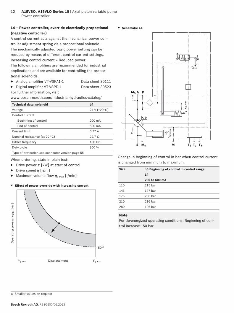
LR – Power controller, fi xed setting L4 – Power controller, electric proportional override
123.
5
2420.
518
0.1
119.
5(P)
295.6114
P242
0.5
119.
5(P)
123.
5
180.
1
41.6295.6
P
CR – Power controller, hydraulic proportional override, high pressure, with stop
PR – Power controller, hydraulic proportional override, high pressure, without stop
123.
5
242
0.5
180.
1
119.
5(P)
295.635
59.5
194.
7
108.5 PCR242
119.
5(P)
123.
5
160.
618
0.1
92.4295.6
59.5
PR
PR P
E2/E6 – Stroke control, electric proportional H3/4/5/6 – Stroke control, hydraulic prop., pilot pressure
5
255
194.
210
119.
5(P)
129.
5
242P
29.5
76.5
131.
210
119.
5(P)
129.
5
242
275.9
194.
235
P
H3/4/5/6
NoteAll controller versions with shuttle valve in P (some according to ordering code position 08 in variance from the standard)

RE 92800/08.2013, Bosch Rexroth AG
Axial piston variable pump | A15VSO, A15VLO Series 10 Dimensions, size 110
29Dimensions [mm]
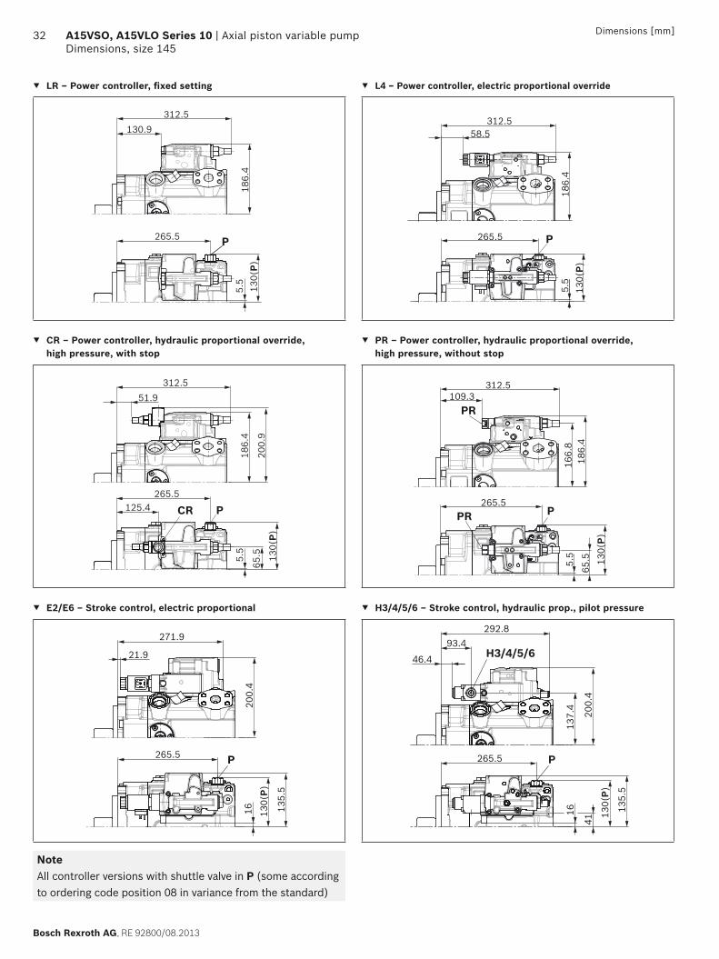
DR – Pressure controller, fi xed setting LRDRS0 – Power controller with pressure controller and load sensing, fi xed setting
123.
5
2420.
518
0.1
119.
5(P)
275.9114
P
123.
5
242
187
0.5
101.
5
180.
1
119.
5(P)
295.6114
PX
DG – Pressure controller, hydraulic, remote controlled DP – Pressure controller, for parallel operation
123.
5
242187
0.5
180.
1
119.
5(P)
101.
5
275.9114
PX
139.
7
242
180.
1
109.425
119.
5(P)
P
DP
MD – Pressure controller with mooring function, fi xed setting
in preparation
NoteAll controller versions with shuttle valve in P (some according to ordering code position 08 in variance from the standard)

Bosch Rexroth AG, RE 92800/08.2013
30 A15VSO, A15VLO Series 10 | Axial piston variable pumpDimensions, size 145
Dimensions [mm]
Dimensions, size 145
LRDRS0 – Power controller with pressure controller, load sensing and with electric swivel angle sensorWithout charge pump, clockwise rotation
123.
311
418
6.4
252
34
310
4.7
133.5
45°
31.8
66.7
61.9
106.4
161.
6
170.
5
161.6
199.
6
199.6
74.6
30
20.6
40.4115.5 (T3)
503
129.5
98.6
131.5
45°
12.2
109.
9
ø152
.4-0
.05
112.7
115.
5
267.7 (T3)
203.9
65.5 107.
5
256.5
128.
516
1.6
111.7
12.7-0.5
107.5
265.5 (P)
W
X
T2MSS
A
T1 A
T1
MA
M
P
PX
X
MA
S
S
A
Z
T2
T3
T39.
31)
158.11)
6.31)
MS
Detail X
Detail W
Detail Z
Flange D4SAE J744
1) Center of gravity

RE 92800/08.2013, Bosch Rexroth AG
Axial piston variable pump | A15VSO, A15VLO Series 10 Dimensions, size 145
31Dimensions [mm]
Splined shaft DIN 5480 Parallel keyed shaft DIN 6885
A2 ‒ W50x2x24x9g B2 ‒ Ø 50 A 14x9x80
M16
x21)
2)
63
ø60
1236
55
44
ø132 M
161)
2)
90
ø60
36
53.5
Ø14
0
ø50
+0.0
18
82
12+0.0
02
Ports Standard Size2) pmax abs [bar]3) Condition7)
A Service line portFastening threads
SAE J5184)
DIN 131 1/4 inM14 x 2; 22 deep
420 O
S Suction port (Without charge pump)Fastening threads
SAE J5184)
DIN 133 inM16 x 2; 24 deep
30 O
T1 Drain port ISO 61495) M42 x 2; 19.5 deep 10 O6)
T2 Drain port ISO 61495) M42 x 2; 19.5 deep 10 X6)
T3 Drain port ISO 61495) M42 x 2; 19.5 deep 10 X6)
CR Pilot signal (only on CR) ISO 6149 M14 x 1.5; 11.5 deep 420 O
PR Pilot signal (only for PR) ISO 6149 M14 x 1.5; 11.5 deep 420 O
H3 to H6 Pilot signal (only for H3, H4, H5 and H6) ISO 6149 M14 x 1.5; 11.5 deep 100 O
DP, DP1 Pilot pressure (only on DP) ISO 6149 M14 x 1.5; 11.5 deep 420 O
X Pilot signal ISO 61495) M14 x 1.5; 11.5 deep 420 O
M Control pressure measurement ISO 61495) M14 x 1.5; 12 deep 420 X
MA Measuring pressure A ISO 61495) M14 x 1.5; 12 deep 420 X
MS Measured suction pressure (only A15VSO) ISO 61495) M14 x 1.5; 12 deep 30 X
P External control pressure (ordering code position 8 version B or C = with external control pressure supply)
ISO 61495) M14 x 1.5; 11.5 deep 50 O
Port P has no function(ordering code position 8 version A = without external control pressure supply)
ISO 61495) M18 x 1.5; 14.5 deep 420 X
1) Center bore according to DIN 332 (thread according to DIN 13)2) For the maximum tightening torques, the general instructions on
page 60 must be observed.3) Momentary pressure spikes may occur depending on the specifi c
application. Keep this in mind when selecting measuring devices and fi ttings.
4) Metric fastening thread in variance from the standard
5) The spot face may be deeper that specifi ed in the standard.6) Depending on the installation position, T1, T2 or T3 must be con-
nected (cf. "Installation instructions" on pages 56 and 57).7) O = Must be connected (plugged on delivery)
X = Plugged (in normal operation)
Key width 14
Bosch Rexroth AG, RE 92800/08.2013
32 A15VSO, A15VLO Series 10 | Axial piston variable pumpDimensions, size 145
Dimensions [mm]
LR – Power controller, fi xed setting L4 – Power controller, electric proportional override
130(
P)265.5
5.5
186.
4
312.5130.9
P
186.
45.
513
0(P)
265.5
58.5312.5
P
CR – Power controller, hydraulic proportional override, high pressure, with stop
PR – Power controller, hydraulic proportional override, high pressure, without stop
130(
P)
265.5
5.5
186.
4
312.551.9
65.5
200.
9
125.4 PCR
166.
818
6.4
5.5
130(
P)
265.5
109.3312.5
65.5
PR
PR P
E2/E6 – Stroke control, electric proportional H3/4/5/6 – Stroke control, hydraulic prop., pilot pressure
21.9
271.9
200.
416 13
0(P)
135.
5
265.5 P
46.4
93.4
137.
416 13
0(P)
135.
5
265.5
292.8
200.
441
P
H3/4/5/6
NoteAll controller versions with shuttle valve in P (some according to ordering code position 08 in variance from the standard)

RE 92800/08.2013, Bosch Rexroth AG
Axial piston variable pump | A15VSO, A15VLO Series 10 Dimensions, size 145
33Dimensions [mm]
DR – Pressure controller, fi xed setting LRDRS0 – Power controller with pressure controller and load sensing, fi xed setting
130(
P)
265.55.
518
6.4
129.
5
292.8130.9
P
130(
P)
265.5
203.9
5.5
107.
518
6.4
312.5130.9
PX
DG – Pressure controller, hydraulic, remote controlled DP – Pressure controller, for parallel operation
170.
418
6.4
203.9294.9
265.5203.9
5.5
107.
513
0(P)
X
X P
137.
420
0.4
25.1
97.1292.8
7.8
85 130(
P)13
5.5
DP
DP1 DP265.5 P
MD – Pressure controller with mooring function, fi xed setting
in preparation
NoteAll controller versions with shuttle valve in P (some according to ordering code position 08 in variance from the standard)

Bosch Rexroth AG, RE 92800/08.2013
34 A15VSO, A15VLO Series 10 | Axial piston variable pumpDimensions size 175
Dimensions [mm]
Dimensions size 175
LRDRS0 – Power controller with pressure controller, load sensing and with electric swivel angle sensorWithout charge pump, clockwise rotation
Detail X
Detail W
Flange E4SAE J744
Detail Z
M10 x 1.75; 20 deep Thread for eye bolt (additional thread on underside of case)
134.
512
919
2.4
25
269.5327.5
5
142
45°
31.8
66.7
61.9
106.4
224.
517
6.6
224.5
262.
5
262.5
74
32
20.6
43536
133.7
123 (T3)
105
140
45°
13
118
ø165
.1-0
.05
117.5
282.5 (T3)
216.2
69.7 12
3
270.5
140
173.
1
119
15.9-0.5
111.7
111.
7
T3
W
X
T2 S
A
T1 A
T1
MA
M
P
X
X
MA
T3
S
S
MS
A
Z
T2
8.51)
5.61)
159.71)
P
279.5 (P)MS
36
1) Center of gravity

RE 92800/08.2013, Bosch Rexroth AG
Axial piston variable pump | A15VSO, A15VLO Series 10 Dimensions size 175
35Dimensions [mm]
LRDRS0 – Power controller with pressure controller, load sensing and with electric swivel angle sensorWith charge pump, clockwise rotation
Detail X
Detail W
Flange E4SAE J744
Detail Z
M10 x 1.75; 20 deep Thread for eye bolt (additional thread on underside of case)
25
317.5
4
142
45°
31.8
66.7
69.9
120.7
224.
5
176.
6
224.5
262.
5
262.5
90
32
20.6
2275
6
133.7
123 (T3)
105
140
45°
13
125
ø165
.1-0
.05
117.5
69.7 12
711
1.7
270.5
136
173.
1
119
111.7
376.5394.5
134.
512
919
2.4
W
X
T2 S
A
T1 A
T1
MA
M
P
MA
S
S
A
X
X
P
T2
Z
282.5 (T3)
216.215.9-0.5
279.5 (P)
6.81)
189.81)
5.71)
T3
36
1) Center of gravity

Bosch Rexroth AG, RE 92800/08.2013
36 A15VSO, A15VLO Series 10 | Axial piston variable pumpDimensions size 175
Dimensions [mm]
Splined shaft DIN 5480 Parallel keyed shaft DIN 6885
A2 ‒ W50x2x24x9g B2 ‒ Ø 50 A 14x9x80
M16
x21)
2)
62
ø60
1236
54
45
ø140 M
161)
2)
90
ø60
36
53.5
Ø14
0
ø50
+0.0
18
82
12+0.0
02
Ports Standard Size2) pmax abs [bar]3) Condition7)
A Service line portFastening threads
SAE J5184)
DIN 131 1/4 inM14 x 2; 22 deep
420 O
S Suction port (Without charge pump)Fastening threads
SAE J5184)
DIN 133 inM16 x 2; 24 deep
30 O
S Suction port (with charge pump)Fastening threads
SAE J5184)
DIN 133 1/2 inM16 x 2; 24 deep
2 OO
T1 Drain port ISO 61495) M33 x 2; 19 deep 10 O6)
T2 Drain port ISO 61495) M33 x 2; 19 deep 10 X6)
T3 Drain port ISO 61495) M33 x 2; 19 deep 10 X6)
CR Pilot signal (only on CR) ISO 6149 M14 x 1.5; 11.5 deep 420 O
PR Pilot signal (only for PR) ISO 6149 M14 x 1.5; 11.5 deep 420 O
H3 to H6 Pilot signal (only for H3, H4, H5 and H6) ISO 6149 M14 x 1.5; 11.5 deep 100 O
X Pilot signal ISO 61495) M14 x 1.5; 11.5 deep 420 O
DP, DP1 Pilot pressure (only on DP) ISO 6149 M14 x 1.5; 11.5 deep 420 O
M Control pressure measurement ISO 61495) M14 x 1.5; 12 deep 420 X
MA Measuring pressure A ISO 61495) M14 x 1.5; 12 deep 420 X
MS Measured suction pressure (only A15VSO) ISO 61495) M14 x 1.5; 12 deep 30 X
P External control pressure(ordering code position. 8 version B or C = with external control pressure supply)
ISO 61495) M14 x 1.5; 11.5 deep 50 O
Port P has no function(ordering code position 8 version A = without external control pressure supply)
ISO 61495) M18 x 1.5; 14.5 deep 420 X
1) Center bore according to DIN 332 (thread according to DIN 13)2) For the maximum tightening torques, the general instructions on
page 60 must be observed.3) Momentary pressure spikes may occur depending on the specifi c
application. Keep this in mind when selecting measuring devices and fi ttings.
4) Metric fastening thread in variance from the standard
5) The spot face may be deeper that specifi ed in the standard.6) Depending on the installation position, T1, T2 or T3 must be con-
nected (cf. "Installation instructions" on pages 56 and 57).7) O = Must be connected (plugged on delivery)
X = Plugged (in normal operation)
Key width 14

RE 92800/08.2013, Bosch Rexroth AG
Axial piston variable pump | A15VSO, A15VLO Series 10 Dimensions size 175
37Dimensions [mm]
LR – Power controller, fi xed setting L4 – Power controller, electric proportional override
9.7
192.
4
143.
5
279.5
134.
5(P)
P
143.2324.8
192.
4
70.8324.8
9.7
134.
5(P)
279.5P
143.
5
CR – Power controller, hydraulic proportional override, high pressure, with stop
PR – Power controller, hydraulic proportional override, high pressure, without stop
9.7
192.
4
137.7
69.7
207
279.5
PCR
64.2324.8
143.
513
4.5(
P)
172.
919
2.4
121.6324.8
9.7
134.
5(P)
133.
7
279.5
69.7
PR
PR P
143.
5
E2/E6 – Stroke control, electric proportional H3/4/5/6 – Stroke control, hydraulic prop., pilot pressure
20.2
134.
5(P)
139.
7
206.
5
279.5 P
34.2284.2
143.
5
45.2
134.
5(P)
139.
7
143.
5
279.5
20.2
206.
5
P
H3/4/5/6105.7281.1
58.714
3.5
NoteAll controller versions with shuttle valve in P (some according to ordering code position 08 in variance from the standard)

Bosch Rexroth AG, RE 92800/08.2013
38 A15VSO, A15VLO Series 10 | Axial piston variable pumpDimensions size 175
Dimensions [mm]
DR – Pressure controller, fi xed setting LRDRS0 – Power controller with pressure controller and load sensing, fi xed setting
9.7
192.
413
4.5(
P)
279.5P
143.2305.1
143.
5
9.7
143.
5
192.
4
134.
5(P)
279.5216.2
111.
7
PX
143.2324.8
DG – Pressure controller, hydraulic, remote controlled DP – Pressure controller, for parallel operation
176.
519
2.4
216.2143.2
307.2
279.5
9.7
111.
713
4.5(
P)
X
X P
143.
5 49.7
3.6 13
9.7
89.2
143.
5
206.
5
109.437.4
DP
DP PDP1
143.
5
279.5
305.1
134.
5(P)
MD – Pressure controller with mooring function, fi xed setting
in preparation
NoteAll controller versions with shuttle valve in P (some according to ordering code position 08 in variance from the standard)

RE 92800/08.2013, Bosch Rexroth AG
Axial piston variable pump | A15VSO, A15VLO Series 10 Dimensions, size 210
39Dimensions [mm]
Dimensions, size 210
LRDRS0 – Power controller with pressure controller, load sensing and with electric swivel angle sensorWithout charge pump, clockwise rotation
Detail X
Detail W
Flange E4SAE J744
Detail Z
M12 x 1.75; 22 deep Thread for eye bolt (additional thread on underside of case)
184.
322
4.5
262.
5
137.
313
020
0.2
25.8
282.5344.8
8
152
45°
36.5
79.4
69.9
120.7
224.5262.5
90
38
20.6
4556
138
132 (T3)
109
148
45°
18
128
ø165
.1-0
.05
120
127
299.6 (T3)
230.7
74 116
285.6
145.
517
8.6
129
15.9-0.50
4.5
293.6 (P)
W
X
T2 S
A
T1A
T1
MA
MSM
P
T3
X
X
MA
S
S
Z
T2
A
T3
43.5
116
7.81)
171.71)
51)
P
MS
1) Center of gravity

Bosch Rexroth AG, RE 92800/08.2013
40 A15VSO, A15VLO Series 10 | Axial piston variable pumpDimensions, size 210
Dimensions [mm]
LRDRS0 – Power controller with pressure controller, load sensing and with electric swivel angle sensorWith charge pump, clockwise rotation
Detail X
Detail W
Flange E4SAE J744
Detail Z
M12 x 1.75; 22 deep Thread for eye bolt (additional thread on underside of case)
333.8
7
150
45°
36.5
79.4
69.9
120.7
184.
322
4.5
224.5
262.
5
262.5
90
38
20.6
1680
138
132 (T3)
109
148
45°
18
135
ø165
.1-0
.05
122
132
74 116
285.6
142.
517
8.6
125
15.9-0.50
4.5
393.8411.8
116
6.91)
299.6 (T3)
230.7292.8 (P)
25.8
137.
313
020
0.2
W
X
T2 S
A
T1 A
T1
MA
M
P
X
X
MA
S
S
A
T3
P
T3
Z
4.31)
1951)T2
43.5
1) Center of gravity

RE 92800/08.2013, Bosch Rexroth AG
Axial piston variable pump | A15VSO, A15VLO Series 10 Dimensions, size 210
41Dimensions [mm]
Splined shaft DIN 5480 Parallel keyed shaft DIN 5480
A2 ‒ W50x2x24x9g B2 ‒ Ø 50 A 14x9x80
M16
x21)
2)
62
ø60
1238
54
45
ø140 M
161)
2)
90
ø60
36
53.5
Ø14
0
ø50
+0.0
18
82
12+0.0
02
Ports Standard Size2) pmax abs [bar]3) Condition7)
A Service line portFastening threads
SAE J5184)
DIN 131 1/2 inM16 x 2; 21 deep
420 O
S Suction port (Without charge pump)Fastening threads
SAE J5184)
DIN 133 1/2 inM16 x 2; 24 deep
30 O
S Suction port (with charge pump)Fastening threads
SAE J5184)
DIN 133 1/2 inM16 x 2; 24 deep
2 O
T1 Drain port ISO 61495) M42 x 2; 19.5 deep 10 O6)
T2 Drain port ISO 61495) M42 x 2; 19.5 deep 10 X6)
T3 Drain port ISO 61495) M42 x 2; 19.5 deep 10 X6)
CR Pilot signal (only on CR) ISO 6149 M14 x 1.5; 11.5 deep 420 O
PR Pilot signal (only for PR) ISO 6149 M14 x 1.5; 11.5 deep 420 O
H3 to H6 Pilot signal (only for H3, H4, H5 and H6) ISO 6149 M14 x 1.5; 11.5 deep 100 O
X Pilot signal ISO 61495) M14 x 1.5; 11.5 deep 420 O
DP, DP1 Pilot pressure (only on DP) ISO 6149 M14 x 1.5; 11.5 deep 420 O
M Control pressure measurement ISO 61495) M14 x 1.5; 12 deep 420 X
MA Measuring pressure A ISO 61495) M14 x 1.5; 12 deep 420 X
MS Measured suction pressure (only A15VSO) ISO 61495) M14 x 1.5; 12 deep 30 X
P External control pressure (ordering code position 8 version B or C = with external control pressure supply)
ISO 61495) M14 x 1.5; 11.5 deep 50 O
Port P has no function(ordering code position 8 version A = without external control pressure supply)
ISO 61495) M14 x 1.5; 11.5 deep 420 X
Key width 14
1) Center bore according to DIN 332 (thread according to DIN 13)2) For the maximum tightening torques, the general instructions on
page 60 must be observed.3) Momentary pressure spikes may occur depending on the specifi c
application. Keep this in mind when selecting measuring devices and fi ttings.
4) Metric fastening thread in variance from the standard
5) The spot face may be deeper that specifi ed in the standard.6) Depending on the installation position, T1, T2 or T3 must be con-
nected (cf. "Installation instructions" on pages 56 and 57).7) O = Must be connected (plugged on delivery)
X = Plugged (in normal operation)

Bosch Rexroth AG, RE 92800/08.2013
42 A15VSO, A15VLO Series 10 | Axial piston variable pumpDimensions, size 210
Dimensions [mm]
LR – Power controller, fi xed setting L4 – Power controller, electric proportional override
1420
0.2
136(
P)
293.6
138
149
P
157.7339.3
200.
2
85.3339.3
14 136(
P)13
814
9
293.6 P
CR – Power controller, hydraulic proportional override, high pressure, with stop
PR – Power controller, hydraulic proportional override, high pressure, without stop
1420
0.2
136(
P)
152.2
138
149
7421
4.7
293.6
PCR
78.7339.3
180.
620
0.2
136.1339.3
14 74 136(
P)13
814
9
293.6
PR
PR P
E2/E6 – Stroke control, electric proportional H3/4/5/6 – Stroke control, hydraulic prop., pilot pressure
24.5
136(
P)14
414
9
214.
2
293.6 P
48.7298.6
49 136(
P)14
414
9
293.6
24.5
151.
221
4.2
P
H3/4/5/6120.2295.6
73.2
NoteAll controller versions with shuttle valve in P (some according to ordering code position 08 in variance from the standard)
RE 92800/08.2013, Bosch Rexroth AG
Axial piston variable pump | A15VSO, A15VLO Series 10 Dimensions, size 210
43Dimensions [mm]
DR – Pressure controller, fi xed setting LRDRS0 – Power controller with pressure controller and load sensing, fi xed setting
1420
0.2
136(
P)
293.6
138
149
P
157.7319.6
1420
0.2
136(
P)
293.6230.7
116
138
149
PX
157.7339.3
DG – Pressure controller, hydraulic, remote controlled DP – Pressure controller, for parallel operation
184.
220
0.2
157.7321.7
293.6230.7
14 116
136(
P)13
814
9
X
X P
136(
P)
293.6P
151.
2 214.
2
51.9123.9
295.6
0.7 54
144
149
DP
DP
MD – Pressure controller with mooring function, fi xed setting
in preparation
NoteAll controller versions with shuttle valve in P (some according to ordering code position 08 in variance from the standard)

Bosch Rexroth AG, RE 92800/08.2013
44 A15VSO, A15VLO Series 10 | Axial piston variable pumpDimensions size 280
Dimensions [mm]
Dimensions size 280
LRDRS0 – Power controller with pressure controller, load sensing and with electric swivel angle sensorWithout charge pump, clockwise rotation
T3
P
A
6.51)
195.81)4.
21)
156.
413
820
8.3
34
43
324
387
10
165
45°
36.5
79.4
69.9
120.7
224.
5
192.
4
224.5
262.
5
262.5
90
38
20.6
50625
144
140 (T3)
121
162
45°
15
135
16
5.1-0
.05
140
140
332 (T3)
261.4
80 122
317
154.
518
7.6
142
15.9-0.5
329 (P)
W
X
T2 S
A
T1 A
T1
MA
M
P
MS
T3
X
X
MA
S
S
Z
T2
122
MS
Detail X
Flange E4SAE J744
Detail W
Detail Z
M12 x 1.75; 22 deep Thread for eye bolt (additional thread on underside of case)
1) Center of gravity

RE 92800/08.2013, Bosch Rexroth AG
Axial piston variable pump | A15VSO, A15VLO Series 10 Dimensions size 280
45Dimensions [mm]
LRDRS0 – Power controller with pressure controller, load sensing and with electric swivel angle sensorWith charge pump, clockwise rotation
Z
T2
A
P
T3
T3
156.
413
820
8.3
43
34
359
10
165
45°
36.5
79.477
.8
130.2
224.5262.5
100
38
20.6
18905
144
121
162
45°
15
144
16
5.1-
0.05
140
145
261.4
80 122
317
150
187.
6
142
15.9-0.5
425443
122
332 (T3)
329 (P)
224.
5
192.
4
262.
5
W
T2 S
A
T1 A
T1
MA
M
P
X
X
MA
S
S
3.81)
2351)
3.21)
140 (T3)
X
1) Center of gravity
Detail X
Flange E4SAE J744
Detail W
Detail Z
M12 x 1.75; 22 deep Thread for eye bolt (additional thread on underside of case)

Bosch Rexroth AG, RE 92800/08.2013
46 A15VSO, A15VLO Series 10 | Axial piston variable pumpDimensions size 280
Dimensions [mm]
Splined shaft DIN 5480 Parallel keyed shaft DIN 6885
A4 ‒ W60x2x28x9g B4 ‒ Ø 60 A 18x11x100
M20
x2.5
1) 2
)
65.9
ø70
1542
58
47
ø140
ø140
M20
x 2
.51)
2)
112.9
ø70
15
42
64
ø60
+0.0
30
105
+0.0
11
Ports Standard Size2) pmax abs [bar]3) Condition7)
A Service line portFastening threads
SAE J5184)
DIN 131 1/2 inM16 x 2; 21 deep
420 O
S Suction port (Without charge pump)Fastening threads
SAE J5184)
DIN 133 1/2 inM16 x 2; 24 deep
30 O
S Suction port (with charge pump)Fastening threads
SAE J5184)
DIN 134 inM16 x 2; 24 deep
2 O
T1 Drain port ISO 61495) M42 x 2; 19.5 deep 10 O6)
T2 Drain port ISO 61495) M42 x 2; 19.5 deep 10 X6)
T3 Drain port ISO 61495) M42 x 2; 19.5 deep 10 X6)
CR Pilot signal (only on CR) ISO 6149 M14 x 1.5; 11.5 deep 420 O
PR Pilot signal (only for PR) ISO 6149 M14 x 1.5; 11.5 deep 420 O
H3 to H6 Pilot signal (only for H3, H4, H5 and H6) ISO 6149 M14 x 1.5; 11.5 deep 100 O
X Pilot signal ISO 61495) M14 x 1.5; 11.5 deep 420 O
DP, DP1 Pilot pressure (only on DP) ISO 6149 M14 x 1.5; 11.5 deep 420 O
M Control pressure measurement ISO 61495) M14 x 1.5; 12 deep 420 X
MA Measured pressure A ISO 61495) M14 x 1.5; 12 deep 420 X
MS Measured suction pressure (only A15VSO) ISO 61495) M14 x 1.5; 12 deep 3 X
P External control pressure (ordering code position 8 version B or C = with external control pressure supply)
ISO 61495) M14 x 1.5; 11.5 deep 50 O
Port P has no function(ordering code position 8 version A = without external control pressure supply)
ISO 61497) M18 x 1.5; 14.5 deep 420 X
1) Center bore according to DIN 332 (thread according to DIN 13)2) For the maximum tightening torques, the general instructions on
page 60 must be observed.3) Momentary pressure spikes may occur depending on the specifi c
application. Keep this in mind when selecting measuring devices and fi ttings.
4) Metric fastening thread in variance from the standard
5) The spot face may be deeper that specifi ed in the standard.6) Depending on the installation position, T1, T2 or T3 must be con-
nected (cf. "Installation instructions" on pages 56 and 57).7) O = Must be connected (plugged on delivery)
X = Plugged (in normal operation)
Key width 18

RE 92800/08.2013, Bosch Rexroth AG
Axial piston variable pump | A15VSO, A15VLO Series 10 Dimensions size 280
47Dimensions [mm]
LR – Power controller, fi xed setting L4 – Power controller, electric proportional override
145.
520
8.3
188.4
146.
5(P)
329
20
370
P
158
144(
P)
208.
3
116
145.
5
329
20
370
P
CR – Power controller, hydraulic proportional override, high pressure, with stop
PR – Power controller, hydraulic proportional override, high pressure, without stop
80 145.
5
PCR
222.
8
109.4
146.
5(P)
329
20
370
182.9
158
166.8370
329
20 145.
5(P)
80
PR
PPR
208.
3
188.
7
158
E2/E6 – Stroke control, electric proportional H3/4/5/6 – Stroke control, hydraulic prop., pilot pressure
222.
3
329.4
79.4
P
150
329
30.5
145.
5(P)
158
222.
3
150.9104.4
329.4
159.
3
H3/4/5/6
P
150
145.
5(P)
329
30.5 55
.5
158
NoteAll controller versions with shuttle valve in P (some according to ordering code position 08 in variance from the standard)

Bosch Rexroth AG, RE 92800/08.2013
48 A15VSO, A15VLO Series 10 | Axial piston variable pumpDimensions size 280
Dimensions [mm]
DR – Pressure controller, fi xed setting LRDRS0 – Power controller with pressure controller and load sensing, fi xed setting
145.
5(P)
208.
3
188.4
146.
5
32920
350.3
P
158
145.
5(P)
122
208.
3
188.4
146.
5
329261.4
20
370
PX
158
DG – Pressure controller, hydraulic, remote controlled DP – Pressure controller, for parallel operation
192.
320
8.3
188.4261.4
352.4
20 122
145.
5(P)
329
X
X P
158
DP
DP1 DP
6.7
60 99.5 15
0
159.
322
2.3
82.6154.6
350.3
158
145.
5(P)
329
P
MD – Pressure controller with mooring function, fi xed setting
in preparation
NoteAll controller versions with shuttle valve in P (some according to ordering code position 08 in variance from the standard)
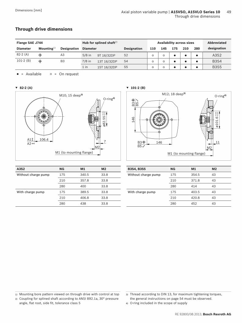
RE 92800/08.2013, Bosch Rexroth AG
Axial piston variable pump | A15VSO, A15VLO Series 10 Through drive dimensions
49Dimensions [mm]
Through drive dimensions
Flange SAE J744 Hub for splined shaft2) Availability across sizes Abbreviated
designationDiameter Mounting1) Designation Diameter Designation 110 145 175 210 280
82-2 (A) A3 5/8 in 9T 16/32DP S2 A3S2101-2 (B) B3 7/8 in 13T 16/32DP S4 B3S4
1 in 15T 16/32DP S5 B3S5
= Available = On request
82-2 (A) 101-2 (B)
ø82.
55+0
.05
+0.0
2
M2
7106.4A1A2
M1 (to mounting fl ange)
M10; 15 deep3)
O-ring4)
M12; 18 deep3)
ø101
.6+0
.05
+0.0
2
M2
11146
146
B3B5
B3 B5
M1 (to mounting fl ange)
O-ring4)
A3S2 NG M1 M2 B3S4, B3S5 NG M1 M2
Without charge pump 175 340.5 33.8 Without charge pump 175 354.5 43
210 357.8 33.8 210 371.8 43
280 400 33.8 280 414 43
With charge pump 175 389.5 33.8 With charge pump 175 403.5 43
210 406.8 33.8 210 420.8 43
280 438 33.8 280 452 43
1) Mounting bore pattern viewed on through drive with control at top 2) Coupling for splined shaft according to ANSI B92.1a, 30° pressure
angle, fl at root, side fi t, tolerance class 5
3) Thread according to DIN 13, for maximum tightening torques, the general instructions on page 54 must be observed.
4) O-ring included in the scope of supply

Bosch Rexroth AG, RE 92800/08.2013
50 A15VSO, A15VLO Series 10 | Axial piston variable pumpThrough drive dimensions
Dimensions [mm]
Flange SAE J744 Splined shaft Availability across sizes Abbreviated
designationDiameter Mounting1) Designation Diameter Designation 110 145 175 210 280
127-2 (C) C3 1 1/4 in 14T 12/24DP2) S7 C3S71 1/2 in 17T 12/24DP2) S9 C3S9
152-4 (D) D4 W45x2x21x9g3) A1 D4A1W50x2x24x9g3) A2 D4A2
165-4 (E) E4 W50x2x24x9g3) A2 E4A2W60x2x28x9g3) A4 E4A4
= Available = On request
127-2 (C) 165-4 (E)ø1
27+0
.05
+0.0
2
M2
14181
181
C3
C3
M1 (to mounting fl ange)
O-ring5)M16; 24 deep4)
ø165
.1+0
.07
+0.0
2
224.5M2
17
224.
5E4
E4
M1 (to mounting fl ange)
M204) O-ring5)
C3S7 NG M1 M2 E4A2 NG M1 M2
Without charge pump 175 354.5 58.1 Without charge pump 175 363.5 58.1
210 371.8 58.1 210 380.8 58.1
280 414 58.1 280 423 58.1
With charge pump 175 403.5 58.1 With charge pump 175 412.5 58.1
210 420.8 58.1 210 429.8 58.1
280 452 58.1 280 461 58.1
C3S9 NG M1 M2 E4A4 NG M1 M2
Without charge pump 280 414 63.8 Without charge pump 280 423 68
With charge pump 280 452 63.8 With charge pump 280 461 68
1) Mounting bore pattern viewed on through drive with control at top.
2) Hub for splined shaft according to ANSI B92.1a, 30° pressure an-gle, fl at root, side fi t, tolerance class 5
3) Hub for splined shaft according to DIN 54804) Thread according to DIN 13, for maximum tightening torques, the
general instructions on page 54 must be observed.5) O-ring included in the scope of supply

RE 92800/08.2013, Bosch Rexroth AG
Axial piston variable pump | A15VSO, A15VLO Series 10 Through drive dimensions
51Dimensions [mm]
Flange, ISO 3019-2 (metric) Hub for splined shaft2) Availability across sizes Abbreviated
designationDiameter Mounting1) Designation Diameter Designation 110 145 175 210 280
80-2 K3 3/4 in 11T 16/32DP S3 K3S3K5 3/4 in 11T 16/32DP S3 K5S3
100-2 L5 7/8 in 13T 16/32DP S4 L5S4
= Available = On request
80-2
ø80.
00+0
.05
+0.0
2
M2
7
109
45°
45°
K5
M1 (to mounting fl ange)
M10; 15 deep3)
O-ring4)
K5S3 NG M1 M2
Without charge pump 210 357.8 40
With charge pump 210 395.8 40
1) Mounting bore pattern viewed on through drive with control at top.2) Hub for splined shaft according to ANSI B92.1a, 30° pressure an-
gle, fl at root, side fi t, tolerance class 5
3) Thread according to DIN 13, for maximum tightening torques, the general instructions on page 54 must be observed.
4) O-ring included in the scope of supply

Bosch Rexroth AG, RE 92800/08.2013
52 A15VSO, A15VLO Series 10 | Axial piston variable pumpThrough drive dimensions
Dimensions [mm]
Flange, ISO 3019-2 (metric) Hub for splined shaft2) Availability across sizes Abbreviated
designationDiameter Mounting1) Designation Diameter Designation 110 145 175 210 280
180-4 R4 1 1/2 in 17T 12/24DP S9 R4S91 3/4 in 13T 8/16DP T1 R4T1
= Available = On request
180-4
ø180
+0.0
5–0
.02
M2
9158.4
158.
4
R4
R4
M1 (to mounting fl ange)
M16; through3)
O-ring4)
R4S9 NG M1 M2
Without charge pump 280 419 70
With charge pump 280 467 70
1) Mounting bore pattern viewed on through drive with control at top2) Hub for splined shaft according to ANSI B92.1a, 30° pressure an-
gle, fl at root, side fi t, tolerance class 5
3) Thread according to DIN 13, for maximum tightening torques, the general instructions on page 54 must be observed.
4) O-ring included in the scope of supply

RE 92800/08.2013, Bosch Rexroth AG
Axial piston variable pump | A15VSO, A15VLO Series 10 Overview of mounting options
53Dimensions [mm]
Overview of mounting options
Through drive1) Mounting options – Pump 2
FlangeSAE J744
Hub for splined shaft
Abbreviation A15VSO/10A15VLO/10Size (shaft)
A10VSO/31Size (shaft)
A10VSO/32 Size (shaft)
A10VO/52 and 53 Size (shaft)
External gear pump
82-2 (A) 5/8 in A_S2 – – – 10, 18 (U) Series FSize 4 to 222)
101-2 (B) 7/8 in B3S4 – – – 28 (R, S);45 (U, W)
Series NSize 20 to 362)
1 in B3S5 – – – 45 (R, S); 60, 63 (U, W)
PGH4
127-2 (C) 1 1/4 in C3S7 – – – 85, 100 (U, W) –1 1/2 in C3S9 – – – 85, 100 (S) PGH5
152-4 (D) W45 D4A1 110 (A1) – – – –W50 D4A2 145 (A2) – – – –
165-4 (E) W50 E4A2 175; 210 (A2)
– – – –
W60 E4A4 280 (A4) – – – –
Flange(metric)
Hub for splined shaft
Abbreviation A15VSO/10A15VLO/10Size (shaft)
A10VSO/31Size (shaft)
A10VSO/32Size (shaft)
A10VO/52 and 53Size (shaft)
External gear pump
80-2 3/4 in K_S3 – 18 (S, R) – 10 (S) –
100-2 7/8 in L5S4 – 28 (S, R) – – –
160-4 1 1/4 in P4S7 – – 71 (S, R) – –180-4 1 1/2 in R4S9 – – 100 (S) – –
1 3/4 in R4T1 – 140 (S) 140, 180 (R) – –125-4 1 in M4S5 – – 45 (S, R) – –140-4 W40 N4Z9 – – – –
1) Other through drives on request2) Bosch Rexroth recommends special versions of the external gear
pumps. Please contact us.

Bosch Rexroth AG, RE 92800/08.2013
54 A15VSO, A15VLO Series 10 | Axial piston variable pumpCombination pumps A15V... + A15V...
Dimensions [mm]
Combination pumps A15V... + A15V...
Overall length A
A15VSO (pump 1) A15VSO (pump 2) A15VLO (pump 2)
Size 110 Size 145 Size 175 Size 210 Size 280 Size 175 Size 210 Size 280
D4A1 D4A2 E4A2 E4A2 E4A4 E4A2 E4A2 E4A4
Size 145 – 656 – – – – – –
Size 175 648.5 673.5 691 – – 758 – –
Size 210 665.8 690.8 708.3 725.6 – 775.3 792.6 –
Size 280 699 733 750.5 767.8 810 817.5 834.8 866
A15VLO (pump 1) A15VSO (pump 2) A15VLO (pump 2)
Size 110 Size 145 Size 175 Size 210 Size 280 Size 175 Size 210 Size 280
D4A1 D4A2 E4A2 E4A2 E4A4 E4A2 E4A2 E4A4
Size 175 697.5 722.5 740 – – 807 – –
Size 210 714.8 739.8 757.3 774.6 – 824.3 841.6 –
Size 280 737 771 788.5 805.8 848 855.5 872.8 904
By using combination pumps, it is possible to have inde-pendent circuits without the need for splitter gearboxes. When ordering combination pumps, the type designations of the 1st and 2nd pumps must be linked by a "+".Order example:A15VSO280LRDRA00/10MRVE4A41SE4A40-0+A15VSO280LRDRA00/10MRVE4A41SU0000-0A tandem pump consisting of two equal sizes is permissible without additional supports assuming that the dynamic acceleration does not exceed maximum 10 g (= 98.1 m/s2). For combination pumps consisting of more than two pumps, the mounting fl ange must be rated for the permis-sible mass torque.
A
A15VSO(1st pump)
A15VSO(2nd pump)

RE 92800/08.2013, Bosch Rexroth AG
Axial piston variable pump | A15VSO, A15VLO Series 10 Connector for solenoids
55Dimensions [mm]
Connector for solenoids
HIRSCHMANN DIN EN 175 301-803-A /ISO 4400without bidirectional suppressor diode ___________________H
Type of protection according to DIN/EN 60529 ________ IP65
The seal in the cable fi tting is suitable for lines of diameter 4.5 mm to 10 mm.The line connector box is not included in the scope of supply.This can be supplied by Bosch Rexroth on request(material number: R902602623).
50
Ø37
68.5
65.4
(2)(1)
Mounting bolt M3Tightening torque:MA = 0.5 Nm
Cable fitting M16x1.5Tightening torque:MA = 1.5 - 2.5 Nm
Device connector on solenoidaccording to DIN 43650
Line connector boxDIN EN 175301-803-Aline screw fi tting M16x1.5
1 2
PEA
1 2
PEA
Changing connector orientationIf necessary, you can change the connector orientation by turning the solenoid housing.To do this, proceed as follows:
Loosen the mounting nut (1) of the solenoid. To do this, turn the mounting nut (1) one turn counter-clockwise.
Turn the solenoid body (2) to the desired position. Retighten the mounting nut.
Tightening torque: 5+1 Nm.(WAF 26, 12kt DIN 3124)
On delivery, the connector orientation may diff er from that shown in the brochure or drawing.

Bosch Rexroth AG, RE 92800/08.2013
56 A15VSO, A15VLO Series 10 | Axial piston variable pumpInstallation instructions
Installation instructions
GeneralDuring commissioning and operation, the axial piston unit must be fi lled with hydraulic fl uid and air bled. This must also observed following a relatively long standstill as the axial piston unit may drain back to the reservoir via the hydraulic lines.Particularly in the installation position "drive shaft upwards" fi lling and air bleeding must be carried out completely as there is, for example, a danger of dry running.The case drain fl uid in the pump housing must be directed to the reservoir via the highest available drain port (T1, T2, T3).If several units are combined, the case drain fl uid must be fed off at each pump. If a shared reservoir line is used for this purpose, make sure that the respective case pressure is not exceeded. In the event of pressure diff erences at the drain ports of the units, the shared drain line must be changed so that the minimum permissible case pressure of all connected units is not exceeded in any situation. If this is not possible, separate drain lines must be laid if neces-sary.To achieve favorable noise values, decouple all connecting lines using elastic elements and avoid above-reservoir installation. In all operating conditions, the suction and drain lines must fl ow into the reservoir below the minimum fl uid level. The permissible suction height hS results from the overall loss of pressure; it must not, however, be higher than hS max = 800 mm. The suction pressure at port S must not drop below the minimum value of 0.8 bar absolute (without charge pump) or 0.7 bar absolute (with charge pump) during operation and on a cold start.Make sure that the reservoir design provides suffi cient clear-ance between the suction line and the reservoir line. This prevents the heated, return fl ow from being drawn directly back into the suction line.
NoteIn determine installation positions, an infl uence on the control or regulation should be expected. Gravity, the dead weight and the case pressure could cause slight characteristic shifts and changes in control time.
Installation position See the following examples 1 to 9.Other installation positions are possible following consulta-tion.Recommended installation position: 1 and 2
Below-reservoir installation (standard)Below-reservoir installation means that the axial piston unit is installed outside of the reservoir below the minimum fl uid level.
Installation position Air bleed Filling
1SB
ht minhmin
T1
T3
T2S
T1 S + T1
2SB
ht minhmin
T1
T3
T2 S
T2 S + T2
3SB
ht minhmin
T1
T3
T2
S
T2 S + T2
Key
L Filling / air bleed
S Suction port
T Drain port
SB Baffl e (baffl e plate)
ht min Minimum required immersion depth (200 mm)
hmin Minimum necessary clearance from the reservoir bottom (100 mm)
hES min Minimum necessary height for protection against the axial piston unit draining dry (25 mm)
hS max Maximum permissible suction height (800 mm)

RE 92800/08.2013, Bosch Rexroth AG
Axial piston variable pump | A15VSO, A15VLO Series 10 Installation instructions
57
Above-reservoir installationAbove-reservoir installation means that the axial piston unit is installed above the minimum fl uid level of the reservoir. To prevent the axial piston unit from, a height diff erence of hES min of at least 25 mm must be observed at port T2 in position 6. Observe the maximum permissible suction height hS max = 800 mm.
Installation position Air bleed Filling
4
SBht min
F
hmin
hs max
T1
T2
T3
S
F T1 (F)
5
SB
F
ht minhmin
h s m
ax
T1
T2
T3
S
F T2 (F)
6
ht min
hmin
hs max
SB
F
T1
T2
T3
S
F T2 (F)
Inside-reservoir installationInside-reservoir installation is when the axial piston unit is installed in the reservoir below the minimum fl uid level. The axial piston unit is completely below the hydraulic fl uid.If the minimum fl uid level is equal to or below the upper edge of the pump, see chapter "Above-reservoir installa-tion".Axial piston units with electric components (e.g. electric controls, sensors) must not be installed in a reservoir lower than the fl uid level.ExceptionInstallation of the pump with E2/E6 control only with HIRSCHMANN connector and if mineral hydraulic fl uids are used and the fl uid temperature in the reservoir does not exceed 80 °C
Installation position Air bleed Filling
7
Shmin
ht min
T1
T2T3
SB
Via the high-est port T1
Automatical-ly via the open port T1, by position below hy-draulic fl uid level
8
S
hmin
ht min
T2
T1
T3
SB
Via the high-est port T2
Automatical-ly via the open port T2, by position below hy-draulic fl uid level
9
T2
hmin
ht min
T1
T3
SB
Via the high-est port T2
Automatical-ly via the open port T2, by position below hy-draulic fl uid level

Bosch Rexroth AG, RE 92800/08.2013
58 A15VSO, A15VLO Series 10 | Axial piston variable pumpInstallation instructions
Dimensions [mm]

RE 92800/08.2013, Bosch Rexroth AG
Axial piston variable pump | A15VSO, A15VLO Series 10 Installation instructions
59

60
Bosch Rexroth AG, RE 92800/08.2013
A15VSO, A15VLO Series 10 | Axial piston variable pumpGeneral instructions
Bosch Rexroth AGMobile ApplicationsAn den Kelterwiesen 1472160 Horb a.N., GermanyTel.: [email protected]/brm
© This document, as well as the data, specifi cations and other information set forth in it, are the exclusive property of Bosch Rexroth AG. It may not be reproduced or given to third parties without its consent. The data specifi ed above only serve to describe the product. No statements concerning a certain condition or suitability for a certain application can be derived from our information. The information given does not release the user from the obligation of own judgment and verifi cation. It must be remembered that our products are subject to a natural process of wear and aging.
A15VSO, A15VLO Series 10 | Axial piston variable pumpGeneral instructions
General instructions
The A15VSO and A15VLO pumps are designed to be used in open circuits.
The project planning, installation and commissioning of the axial piston unit requires the involvement of quali-fi ed personnel.
Before using the axial piston unit, please read the cor-responding instruction manual completely and thor-oughly. If necessary, these can be requested from Bosch Rexroth.
During and shortly after operation, there is a risk of burns on the axial piston unit and especially on the solenoids. Take appropriate safety measures (e. g. by wearing protective clothing).
Depending on the operating conditions of the axial piston unit (operating pressure, fl uid temperature), the characteristic may shift.
Service line ports: – The ports and fastening threads are designed for the
specifi ed maximum pressure. The machine or system manufacturer must ensure that the connecting ele-ments and lines correspond to the specifi ed operat-ing conditions (pressure, volume fl ow, hydraulic fl uid, temperature) with the necessary safety factors.
– The service line ports and function ports can only be used to accommodate hydraulic lines.
The data and notes contained herein must be adhered to. Please request a binding installation drawing before
fi nalizing your design.
Not all versions of the product are approved for use in safety functions in accordance with ISO 13849. If you require reliability parameters (e.g. MTTFd) for functional safety, please contact the responsible contact person at Bosch Rexroth.
Pressure controllers do not constitute fuse protection against pressure overload. A separate pressure-relief valve is to be provided in the hydraulic system.
The following tightening torques apply: – Fittings:
Observe the manufacturer's specifi cations regarding the tightening torques of the fi ttings used.
– Fixing screws: For mounting bolts with metric ISO thread according to DIN 13 or thread according to ASME B1.1, we recommend checking the tightening torque individu-ally according to VDI 2230.
– Threaded hole of the axial piston unit: The maximum permissible tightening torques MG max are maximum values of the threaded holes and must not be exceeded. For values, see the following table.
– Threaded plugs: For the metallic threaded plugs supplied with the axial piston unit, the required tightening torques of threaded plugs MV apply. For values, see the follow-ing table.
Ports Maximum permissible tightening torque of the female threads MG max
Required tightening torque of the threaded plugs MV
WAF Hexagon socket of the threaded plugsStandard Thread size
ISO 6149 M14 x 1.5 80 Nm 45 Nm 6 mm
M18 x 1.5 140 Nm 70 Nm 8 mm
M33 x 2 540 Nm 310 Nm 17 mm
M42 x 2 720 Nm 330 Nm 22 mm