Axial-Flux Permanent-Magnet Brushless DC Traction · PDF fileAxial-Flux Permanent-Magnet...
10
International Review of Electrical Engineering (I.R.E.E.), Vol. 6, N. 2 March-April 2011 Manuscript received and revised March 2011, accepted April 2011 Copyright © 2011 Praise Worthy Prize S.r.l. - All rights reserved 760 Axial-Flux Permanent-Magnet Brushless DC Traction Motor for Direct Drive of Electric Vehicle N. A. Rahim, W. P. Hew, A. Mahmoudi Abstract This paper presents the design of an inside-out axial-flux permanent-magnet brushless dc motor for direct traction drive in an electric vehicle. The prototype motor is a double-sided axial-flux permanent-magnet motor with non-slotted stator. The preliminary design had 16 rotor poles, for high torque density and stable rotation at low speed. The design was simulated via Finite Element Method Magnetics (FEMM) Software, for obtainment of design parameters. The motor was fabricated and tested in an in-wheel test-bed. There exist close agreements between the simulated and experimental results. Copyright © 2011 Praise Worthy Prize S.r.l. - All rights reserved. Keywords: Axial-Flux Permanent-Magnet Motor, Electric Vehicle, Finite Element Analysis Nomenclature F rm Vehicle driving resistance f ro Rolling-resistance force f st Climbing-resistance force f l Aerodynamic-resistance force f r Rolling-resistance coefficient M Vehicle mass [kg] g Gravity acceleration [m/s 2 ] Vehicle movement angle Air density C d Air-resistance coefficient S Frontal projected area v Vehicle speed v 0 Headwind speed min Minimum required torque [N m] r Position vector P min Minimum required power [W] m Rotor angular speed [rad/s] a Vehicle acceleration [m/s 2 ] P accel Power required to accelerate [W] P out Rated power Motor efficiency m Number of phases e(t) Phase-air-gap EMF [V] i(t) Phase current [A] T Period of one EMF cycle [s] K p Electrical power waveform factor f e (t) Normalized EMF waveforms f i (t) Normalized current waveforms E pk Peak value of phase-air-gap EMF I pk Phase current peak value I rms Phase current rms value [V] P Number of motor pole pairs K w Winding distribution factor N ph Number of winding turns per phase K i Current waveform factor B g Air-gap flux density [Wb/m 2 ] f e Electrical frequency [Hz] f m Mechanical frequency [Hz] A Electrical loading total [A] Diameter ratio D o Machine stator outer diameter [m] D i Machine stator inner diameter [m] K Electrical loading ratio Ke EMF factor m 1 Number of phases of each stator A r Rotor electrical loading [A] A s Stator electrical loading [A] K L Aspect ratio coefficient D tot Machine outer diameter total [m] L to t Machine axial length total [m] den Torque density [N m/cm 3 ] W cu End-winding protrusion from iron stack [m] D ave Machine stator average diameter [m] K cu Copper fill factor J s Current density [A/m 2 ] L ss Stator slot depth [m] L e Effective axial length of motor [m] L s Stator axial length [m] L cs Stator-core axial length [m] p Average air-gap flux density to its peak value ratio B cs Stator-core flux density [T] L r Rotor axial length [m] L cr Rotor-core axial length [m] L pm Permanent-magnet length [m] B cr Rotor-disc flux density [T] B u Flux density on permanent-magnet surface [T] g Air-gap length [m] µ r Recoil relative permeability of magnet B r Permanent-magnet residual-flux density [T]
Transcript of Axial-Flux Permanent-Magnet Brushless DC Traction · PDF fileAxial-Flux Permanent-Magnet...

International Review of Electrical Engineering (I.R.E.E.), Vol. 6, N. 2March-April 2011
Manuscript received and revised March 2011, accepted April 2011 Copyright © 2011 Praise Worthy Prize S.r.l. - All rights reserved
760
Axial-Flux Permanent-Magnet Brushless DC Traction Motorfor Direct Drive of Electric Vehicle
N. A. Rahim, W. P. Hew, A. Mahmoudi
Abstract � This paper presents the design of an inside-out axial-flux permanent-magnetbrushless dc motor for direct traction drive in an electric vehicle. The prototype motor is adouble-sided axial-flux permanent-magnet motor with non-slotted stator. The preliminary designhad 16 rotor poles, for high torque density and stable rotation at low speed. The design wassimulated via Finite Element Method Magnetics (FEMM) Software, for obtainment of designparameters. The motor was fabricated and tested in an in-wheel test-bed. There exist closeagreements between the simulated and experimental results. Copyright © 2011 Praise WorthyPrize S.r.l. - All rights reserved.
Keywords: Axial-Flux Permanent-Magnet Motor, Electric Vehicle, Finite Element Analysis
NomenclatureFrm Vehicle driving resistancefro Rolling-resistance forcefst Climbing-resistance forcefl Aerodynamic-resistance forcefr Rolling-resistance coefficientM Vehicle mass [kg]g Gravity acceleration [m/s2]
Vehicle movement angleAir density
Cd Air-resistance coefficientS Frontal projected areav Vehicle speedv0 Headwind speed
min Minimum required torque [N m]r Position vectorPmin Minimum required power [W]
m Rotor angular speed [rad/s]a Vehicle acceleration [m/s2]Paccel Power required to accelerate [W]Pout Rated power
Motor efficiencym Number of phasese(t) Phase-air-gap EMF [V]i(t) Phase current [A]T Period of one EMF cycle [s]Kp Electrical power waveform factorfe(t) Normalized EMF waveformsfi(t) Normalized current waveformsEpk Peak value of phase-air-gap EMFIpk Phase current peak valueIrms Phase current rms value [V]P Number of motor pole pairsKw Winding distribution factorNph Number of winding turns per phase
Ki Current waveform factorBg Air-gap flux density [Wb/m2]fe Electrical frequency [Hz]fm Mechanical frequency [Hz]A Electrical loading total [A]
Diameter ratioDo Machine stator outer diameter [m]Di Machine stator inner diameter [m]K Electrical loading ratioKe EMF factorm1 Number of phases of each statorAr Rotor electrical loading [A]As Stator electrical loading [A]KL Aspect ratio coefficientDtot Machine outer diameter total [m]Ltot Machine axial length total [m]
den Torque density [N m/cm3]Wcu End-winding protrusion from iron stack [m]Dave Machine stator average diameter [m]Kcu Copper fill factorJs Current density [A/m2]Lss Stator slot depth [m]Le Effective axial length of motor [m]Ls Stator axial length [m]Lcs Stator-core axial length [m]
p Average air-gap flux density to its peak valueratio
Bcs Stator-core flux density [T]Lr Rotor axial length [m]Lcr Rotor-core axial length [m]Lpm Permanent-magnet length [m]Bcr Rotor-disc flux density [T]Bu Flux density on permanent-magnet surface [T]g Air-gap length [m]µr Recoil relative permeability of magnetBr Permanent-magnet residual-flux density [T]

N. A. Rahim, W. P. Hew, A. Mahmoudi
Copyright © 2011 Praise Worthy Prize S.r.l. - All rights reserved International Review of Electrical Engineering, Vol. 6, N. 2
761
Kd Leakage-flux factorKc Carter factorKf Peak value corrected factor of air-gap flux
densityBgpk Peak value of air-gap flux density [Wb/m2]Pe Electrical power [W]Pm Mechanical power [W]
I. IntroductionProtection of natural environments sparked interest in
electric vehicle (EV), which is non-polluting. EV wasfirst introduced in 1870; it had light electric motor andvery heavy storage batteries. Battery, electric motor,motor drive circuit, and transmission gears make up EVpower system.
Range of EV driving speeds was limited. Researchersand designers keep attempting more-efficient and more-reliable EV power systems. Improvements to eachsubsystem have increased overall efficiency and drivingrange [1]-[6].
Attempts at finding the most suitable EV motor arekeen pursuits of researchers and engineers throughoutthe world. Permanent-magnet motors already developedfor electric vehicles fulfill requirements for, e.g., highpower-density, high efficiency, high starting torque, andhigh cruising speed. Low cost, high speed, low torque-ripple, high reliability, established manufacturingtechnology that includes converter, and absence ofposition sensors make induction motor the preferreddrive system [7]. Compactness, low weight, and highefficiency of permanent-magnet brushless DC motors aresuitable options for EV propulsion [8]-[11]. Motorsdesigned for EV drive can be classified as direct drive[12] or indirect drive [13]. Direct-drive motor is wheel-mounted. Mechanical deferential and transmission gears,including the associated energy losses, are thuseliminated.
Not only is efficiency improved, but vehicle weight isreduced. Slotless AFPM motors have over conventionalradial-flux motors advantages such as high torque-to-weight ratio, high efficiency, adjustable air gap, balancedmotor-stator attractive forces, and better heat-removal[14]-[17].
This paper presents the design of and experimentalwork on slotless AFPM motor for EV. The motor isdesigned for placement inside the wheel of a motorcycle.Its specifications are according to typical vehicledynamics.
Sizing equations of TORUS AFPM machines arederived via generalized sizing equation, to calculatemotor�s power-production potential. The sizing equationis used for optimum machine design. Finite-elementanalysis is then performed in field analysis of theproposed motor topology.
Finally, a prototype motor is fabricated, andexperiments performed, for information on possiblecurrent driving patterns.
II. Design ProcedureII.1. Vehicle Dynamics
A simple vehicle dynamics model to evaluate vehicleperformance is presented. A simplified vehicle drivingresistance or road load (Frm) consists of rolling resistanceforce (fro), climbing resistance force (fst), andaerodynamic drag force (fl):
rm ro st lF f f f (1)
Rolling resistance (fro) is caused by on-road tiredeformation:
ro rf f M g (2)
where fr, M, and g are rolling resistance coefficient,vehicle mass, and gravity acceleration, respectively.Climbing resistance (fst with positive operational sign)and downward force (fst with negative operational sign)are given by:
stf M g Sin (3)
where, is angle of vehicle movement relative tohorizon. Aerodynamic drag force (fl) is air viscousresistance on vehicle:
20
12l df C S v v (4)
where, is air density, Cd is air-resistance coefficient, Sis frontal projected area, v is vehicle speed, and v0 isheadwind speed. Acting as propulsion, driving force isapplied to wheels to overcome driving resistance.Driving force lower than driving resistance does notmake vehicle roll. In angular movement, minimumrequired torque for vehicle propulsion is:
min rmr F (5)
where, r is position vector. Minimum power required isthus:
min minP (6)
where, m is rotor angular speed. Acceleration isimportant to vehicle movement; energy losses caused byit (a) must factor in calculations. Power required toaccelerate EV is thus:
accelP M v a (7)
Power at wheels is:
out accel minP P P (8)

N. A. Rahim, W. P. Hew, A. Mahmoudi
Copyright © 2011 Praise Worthy Prize S.r.l. - All rights reserved International Review of Electrical Engineering, Vol. 6, N. 2
762
Fig. 1. Proposed Driving Cycles for Electric-Vehicle Design
To design EV motor propulsion, vehicle dynamicsshould first be determined. Fig. 1 is EV cruisingscenario, which includes an EV�s typical-trip elementssuch as increasing speed, constant speed, and brakingaction. Power needed by the vehicle is calculated fromthe proposed driving cycle in Fig. 1, together withEquations (1) to (8). Table I lists the parameters used inthe study.
TABLE IPARAMETERS USED IN THIS STUDY
Vehicle SpecificationWeight of Vehicle 80 kgWeight of Passengers 70 kgWheel Radius (Rd) 0.30 mTire Set 3 unitsDrive System Front driveFrontal Area (S) 0.4 m2
Air Resistance Coefficient (Cd) 0.35Tire Resistance Coefficient (fr ) 2.5×10⁻³
Air Density ( ) 1.22 kg/m3
Maximum Speed (vmax) 60 km/h
II.2. Sizing Equation
An optimum design would be maximized torquedensity while desired efficiency is maintained withindesign restrictions and requirements (see Table II).
TABLE IIDESIGN RESTRICTIONS AND REQUIREMENTS
Dimensional ConstraintsStator Outer Diameter 460 mmTotal Axial-Length 80 mmAir-Gap 1 mm
Limits on Power SystemsPermanent Remanence 1.3 TRated Line-to-Line Voltage (rms) 70VInput Phase Current (rms) 30A
RequirementsMaximum Torque 36.5 N.mOutput Power 1.8 kwMotor Efficiency >90%
Main dimensions of each electrical machine aredetermined via electrical-machine-output powerequation. Assuming negligible leakage inductance andresistance, rated power is expressed as [18]:
0
Tout p pk pk
mP e t i t dt mK E IT
(9)
e(t) is phase air-gap EMF, i(t) is phase current, ismachine efficiency, m is number of machine phases, andT period of one EMF cycle. Epk and Ipk are peaks ofphase air-gap EMF and of current, respectively. Kp iselectrical power waveform factor, defined as:
0 0
1 1T Tp e i
pk pk
e t i tK dt f t f t dt
T E I T (10)
where fe(t)=e(t)/Epk and fi(t)=i(t)/Ipk are expressions fornormalized EMF and current waveforms. For effect ofcurrent waveform, current waveform factor (Ki) isdefined and presented:
2
0
1
1
pki
rms T
pk
IK
I i tdt
T I
(11)
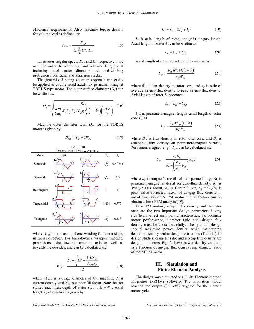
where, Irms is phase-current rms value. Table III liststypical waveforms and their corresponding power-waveform factor (Kp) and current-waveform factor (Ki)[14]. Peak value of phase-air-gap EMF for equation (8)�sAFPM motor is:
2 21pk e ph g ofE K N B Dp
(12)
Ke is EMF factor incorporating winding distributionfactor (Kw) and per-unit portion of air-gap area-totalspanned by machine�s salient poles (if any); Nph isnumber of turns per phase; Bg is flux density in air gap; fis converter frequency; P is machine pole pairs; isAFPM diameter ratio Di /Do; Do is diameter of machineouter surface; Di is diameter of machine inner surface.Equation (9)�s peak phase current is:
1
12 2
opk i
ph
DI A K
m N (13)
where, m1 is number of phases of each stator, and A iselectrical loading. Other authors have provided ageneral-purpose sizing equation for AFPM machines; ittakes the following form:
1
2 2
11 2
112
out e i p L g
o e
mP K K K K B AK m
f D LP
(14)
m1 is number of phases of each stator; Le is effectiveaxial length of the motor; K is electrical loading ratio onrotor and stator; KL is aspect ratio coefficient pertinent toa specific machine structure, with considerations foreffects of losses, temperature rise, and the design�s
N. A. Rahim, W. P. Hew, A. Mahmoudi
Copyright © 2011 Praise Worthy Prize S.r.l. - All rights reserved International Review of Electrical Engineering, Vol. 6, N. 2
763
efficiency requirements. Also, machine torque densityfor volume total is defined as:
2
4
outden
m tot tot
P
D L (15)
m is rotor angular speed, Dtot and Ltot respectively aremachine outer diameter total and machine length totalincluding stack outer diameter and end-windingprotrusion from radial and axial iron stacks.
The generalized sizing equation approach can easilybe applied to double-sided axial-flux permanent-magnetTORUS type motor. The outer surface diameter (Do) canbe written as:
3 2
1
112 2
outo
e p i g
PD
m fK K K ABm p
(16)
Machine outer diameter total Dtot for the TORUSmotor is given by:
2tot o cuD D W (17)
TABLE IIITYPICAL PROTOTYPE WAVEFORMS
Model e(t) i(t) Ki Kp
Sinusoidal 2 0.5Cos
Sinusoidal 2 0.5
Rectangular 1 1
Trapezoidal 1.134 0.777
Triangular 3 0.333
where, Wcu is protrusion of end winding from iron stack,in radial direction. For back-to-back wrapped winding,protrusions exist towards machine axis as well astowards the outsides, and can be calculated as:
2 2
2
avei i
cu scu
ADD DK J
W (18)
where, Dave is average diameter of the machine, Js iscurrent density, and Kcu is copper fill factor. Note that forslotted machines, depth of stator slot is Lss=Wcu. Axiallength Le of machine is given by:
2 2e s rL L L g (19)
Lr is axial length of rotor, and g is air-gap length.Axial length of stator Ls can be written as:
2s cs ssL L L (20)
Axial length of stator core Lcs can be written as:
14
g p ocs
cs
B DL
pB (21)
where Bcs is flux density in stator core, and p is ratio ofaverage air-gap flux density to peak air-gap flux density.Axial length of rotor Lr becomes:
r cr pmL L L (22)
Lpm is permanent-magnet length; axial length of rotorcore Lcr is:
18
u ocr
cr
B DL
pB (23)
where Bcr is flux density in rotor disc core, and Bu isattainable flux density on permanent-magnet surface.Permanent-magnet length Lpm can be calculated as:
r gcr c
fr g
d
BL K g
KB B
K
(24)
where µr is magnet�s recoil relative permeability, Br ispermanent-magnet material residual-flux density, Kd isleakage flux factor, Kc is Carter factor, Kf =Bgpk/Bg ispeak value corrected factor of air-gap flux density inradial direction of AFPM motor. These factors can beobtained from FEM analysis [19].
In AFPM motors, air-gap flux density and diameterratio are the two important design parameters havingsignificant effect on motor characteristics. To optimizemotor performance, diameter ratio and air-gap fluxdensity must be chosen carefully. The optimum designshould maximize power density while maintainingdesired efficiency within design restrictions (Table II). Indesign studies, diameter ratio and air-gap flux density aredesign parameters. Fig. 2 shows power density variationas a function of air-gap flux density, and diameter ratioof the AFPM motor.
III. Simulation andFinite Element Analysis
The design was simulated via Finite Element MethodMagnetics (FEMM) Software. The simulation modelreached the output (2.7 kW) targeted for the electricmotorcycle.

N. A. Rahim, W. P. Hew, A. Mahmoudi
Copyright © 2011 Praise Worthy Prize S.r.l. - All rights reserved International Review of Electrical Engineering, Vol. 6, N. 2
764
Fig. 2. Torque density vs. air-gap flux density and diameter ratio
The FEMM 4.0 software allows calculating in 2-Dspace, so the actual motor had to be modified to the flatmodel, in which all curvatures were developed relative toaverage diameter placed middle of stator core or average
of magnet inner to outer diameter (Dave=(Di+Do)/2).Corresponding materials and circuit currents wereassigned to each block of the model; see Fig. 3(a). Themotor�s 2-D model is symmetric, so 16 magnetic poleswere sliced to reduce simulation/calculation time, and theFEMM model became six magnetic pole pieces. Resultsfrom the model were calculated via LUA programminglanguage, to obtain values for the entire motor. Forsimulation, input parameters needing consideration werepermanent-magnet thickness, air-gap width, andmagnetic properties of all active materials.
Fig. 3(b) shows the magnetic flux density generatedby the permanent magnets.
(a) AFPM motor model in 2D with Fine Meshing (b) Magnetic-flux density FEMM simulation
Figs. 3. AFPM motor simulation using FEMM
The relatively symmetrical distribution of themagnetic-flux density relative to radial symmetrical axisof the magnets indicates current�s negligible influence onresultant magnetic field. Maximum flux density is higherin the stator core than in the rotor because the stator coreis laminated steel that saturates at much higher values.Table IV shows the parameters and the optimizedTORUS motor dimensions calculated via sizingequations.
TABLE IVMOTOR DIMENSIONS
Rotor Inner Diameter 130 mm
Rotor Outer Diameter 230 mmNumber of Windings 48
Number of Turns 12
Magnetic Pole 16
Magnet Thickness 7 mm
Magnet Arc 18o
Magnet Material Nd-Fe-B, N35
Back-Iron Thickness 12 mm
Rated Voltage Line-to-Line(rms)
64V
Rated Phase Current (rms) 30A
Output Power 1.8 kW
FEA was for overview of saturation levels in variousparts of the machine, for comparison of flux densitiesobtained from FEM with sizing analysis.
Table V tabulates results for the comparison, whichwas done at no load and for various parts of the machine.The no-load flux density plots show consistency withsizing analysis, maximum flux density of rotor and ofstator almost equal. Maximum and average air-gap fluxdensities from FEM and from sizing analysis agree, too.
Fig. 4 compares calculated back-EMF againstelectrical angle of the designed motor, from FEA andfrom the no-load experiment at 700 rpm. Theexperiment�s peak back-EMF was 90.4V, slightly lessthan the 95V computed value, agreeing closely with thecomputed waveform.
Fig. 5 compares experiment torque against electricalangle variation, and predicted torque from FEA; bothclosely agree. At 30A rated current and 700rpm ratedspeed, the motor produces 37.4Nm maximum torquewhile the simulation showed 36.78Nm.
TABLE VFLUX DENSITY COMPARISON OF THE DESIGNED MOTOR
Rotor Air-gap statorBcr Bmax Bave Bcs
FEM 1.2 0.81 0.52 1.15Sizing Eq. 1.1 0.8 0.5 1.1

N. A. Rahim, W. P. Hew, A. Mahmoudi
Copyright © 2011 Praise Worthy Prize S.r.l. - All rights reserved International Review of Electrical Engineering, Vol. 6, N. 2
765
Fig. 4. Back-EMF at 700 rpm
Fig. 5. Mechanical torque at 30A
The results show the motor�s ability to fulfill theelectric motorcycle�s power requirement.
IV. Fabrication and Experiment WorksThe motor costs relatively low to manufacture, as
there are no stator teeth. The stator lamination siliconsteels are rolled; no need to wire-cut or laser-cut.Components such as rotor plate and shaft are alsodesigned simply and also cost relatively low tomanufacture. Absence of teeth makes windings difficultto assemble. The motor uses encapsulated thermalconductor epoxy; good for releasing heat, but stands upto only 80°C before its rigidity decreases.
IV.1. Manufacturing
Design challenge in manufacturing the AFPM motoris maintaining air gap between stator and rotor. Magneticinteraction between rotor magnet and stator back-iron isquite large (752 N simulated value for this motor). Theair-gap needs to be the smallest possible; in the design,1mm. Fig. 6 shows the active parts assembled and therotor�s fabricated surface-mounted permanent-magnetmount.
Windings were professionally hand-made; see Fig. 7.They were placed on flat-stator-core surface. To preventthe windings from missing its position and fromvibration during motor operation, a type of epoxy resinwas applied, giving the windings characteristics such asstiffness in working temperature, original dimensions,and good thermal conductivity for heat-release.
Fig. 6. Surface-mounted permanent-magnet arrangementon rotor back-iron
Fig. 7. Toroidal windings for a slot-less stator
The shaft was embedded with stator components; seeFig 8. It kept the stator from returning to a directionopposite to rotor (wheel), so the shaft had to be strongenough for the stator to hold up to the motor�s torque.
Fig. 8. Shaft with hole-through for phase-winding terminal outlet
IV.2. Driving System
To rotate the motor, the stator windings should beenergized in sequence. Knowledge of the rotor�spositioning is important, to understand which winding isenergized following the energizing sequence. Rotor
N. A. Rahim, W. P. Hew, A. Mahmoudi
Copyright © 2011 Praise Worthy Prize S.r.l. - All rights reserved International Review of Electrical Engineering, Vol. 6, N. 2
766
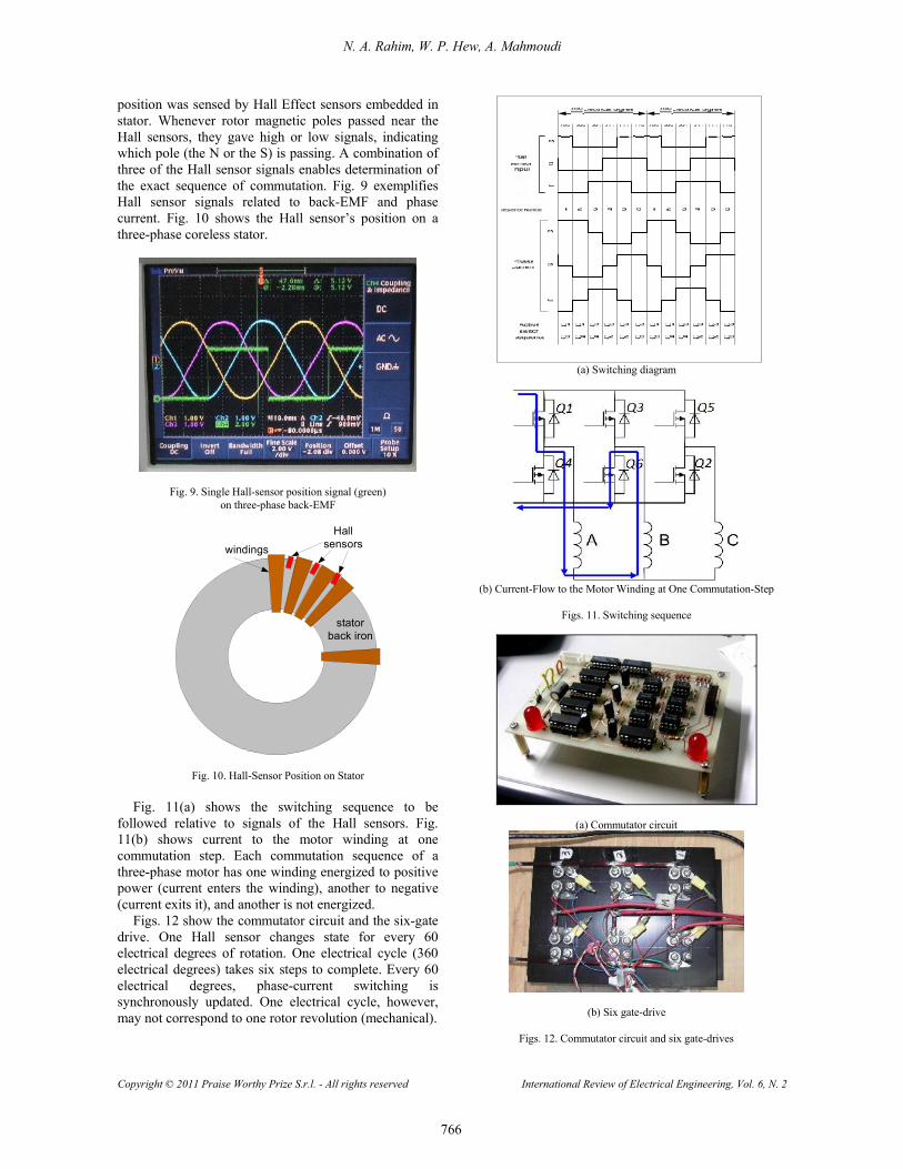
position was sensed by Hall Effect sensors embedded instator. Whenever rotor magnetic poles passed near theHall sensors, they gave high or low signals, indicatingwhich pole (the N or the S) is passing. A combination ofthree of the Hall sensor signals enables determination ofthe exact sequence of commutation. Fig. 9 exemplifiesHall sensor signals related to back-EMF and phasecurrent. Fig. 10 shows the Hall sensor�s position on athree-phase coreless stator.
Fig. 9. Single Hall-sensor position signal (green)on three-phase back-EMF
statorback iron
windings
Hallsensors
Fig. 10. Hall-Sensor Position on Stator
Fig. 11(a) shows the switching sequence to befollowed relative to signals of the Hall sensors. Fig.11(b) shows current to the motor winding at onecommutation step. Each commutation sequence of athree-phase motor has one winding energized to positivepower (current enters the winding), another to negative(current exits it), and another is not energized.
Figs. 12 show the commutator circuit and the six-gatedrive. One Hall sensor changes state for every 60electrical degrees of rotation. One electrical cycle (360electrical degrees) takes six steps to complete. Every 60electrical degrees, phase-current switching issynchronously updated. One electrical cycle, however,may not correspond to one rotor revolution (mechanical).
(a) Switching diagram
(b) Current-Flow to the Motor Winding at One Commutation-Step
Figs. 11. Switching sequence
(a) Commutator circuit
(b) Six gate-drive
Figs. 12. Commutator circuit and six gate-drives

N. A. Rahim, W. P. Hew, A. Mahmoudi
Copyright © 2011 Praise Worthy Prize S.r.l. - All rights reserved International Review of Electrical Engineering, Vol. 6, N. 2
767
Completion of a mechanical rotation is determined byrotor-pole pairs, via number of electrical cycles to berepeated.
One rotor-pole pair completes one electrical cycle:
2e
mf
fP
(25)
fe and fm are electrical and mechanical frequencyrespectively.
V. Experiment ResultsFig. 13 shows the experiment test-bench set-up in
University of Malaya�s Department of ElectricalEngineering, for performance test of the in-wheel motor.A National Instrument Data Acquisition System withLabVIEW� interface was used to obtain test data andplot performance curves. Motor torque and back-EMFwere the main performance parameters obtained. Duringcruising-speed test, secondary measurements such astemperature rise in the motor�s critical parts were alsorecorded.
Figs. 14 and 15 show graphs of back-EMF and torque.Back-EMF maximum output was 180V peak-to-peak,and torque output at rated current (30A) was about 37.4N.m. Back EMF was acquired by mechanically turningthe wheel at a particular speed, and then measuringterminal voltage.
Motor speed was captured on a tachometer, whichobtained the speed from the Hall-sensor pulse train.Under such conditions, the machine then acted asgenerator. At no-load condition, terminal voltage of themachine equaled generated back-EMF. Motor torque wasmeasured on a load-cell force sensor, which wasmounted on a free-rolling shaft. Constant, controlledcurrent was injected into the motor from an inverter. Thewheel was loaded with roller brake. Torque could beincreased to maximum value quickly, and to twice therated value.
Input power (Pi) is the electric energy that runs themotor. Mechanical power delivered by the motor (Pm) istorque and speed, and overall motor efficiency is theratio of input power to mechanical power:
3i ph phP V I (26)
m mP (27)
m
i
PP
(28)
Fig. 16 is a plot of measurement results, showinginput power, mechanical output power, and overallefficiency. Results indicate the machine�s efficiency ismore than 90%.
Fig. 13. Motor experiment test-bench set-up with NI® data logger
Fig. 14. Comparison of Back-EMF results obtained from experimentand from FEM simulation
Fig. 15. Comparison of torque results obtained from experiment andfrom FEM simulation
Fig. 16. The motor�s performance-test results

N. A. Rahim, W. P. Hew, A. Mahmoudi
Copyright © 2011 Praise Worthy Prize S.r.l. - All rights reserved International Review of Electrical Engineering, Vol. 6, N. 2
768
VI. ConclusionThe design, simulation, and testing of an AFPM wheel
motor have been presented. Its high torque-density wasthe parameter of concern. The aim was for maximum-torque-density double-sided AFPM motor. Flux-densitiesof various parts of the motor were compared via sizinganalysis, FEM, and experiment, each at no-load, allagreed in their results.
Results of experiment and simulation show themotor�s actual back-EMF value during testing to be 90.4Vmax at 700rpm. The test result was 4.8% less than that ofthe simulated result (95 Vmax). The difference could bedue to the winding arrangement, which was slightlydifferent during fabrication. Torque produced duringexperiment was 37.4Nm, with 30A input current,whereas torque produced in simulation was about36.78Nm for the same condition. The motor�s designachieved the required motor specification. Its efficiencywas 90%, and its design suits EV application.
References[1] F. J. Perez-Pinal, C. Nunez, R. Alvarez, M. Gallegos, Step by Step
Design of the Power Stage of a Light Electric Vehicle,International Review of Electrical Engineering (IREE), vol. 3. n.1, January-February 2008, pp. 100-109.
[2] P. Naderi, M. Mirsalim, S. M. T. Bathaee, Driving/Regenerationand Stability Enhancement for a Two-Wheel-Drive ElectricVehicle, International Review of Electrical Engineering (IREE),vol. 4 n. 1, January-February 2009, pp. 57-65.
[3] S. Meo, F. Esposito, The �EVALUATOR� Suite for theComputer-aided Analysis of Advanced Automotive ElectricalPower System, International Review of Electrical Engineering(IREE), vol. 2 n. 6, December 200, pp. 751-762.
[4] F. Esposito, V. Isastia, S. Meo: Overview on Automotive EnergyStorage Systems, International Review of Electrical Engineering(IREE), vol. 4 n. 6, November-December 2009, pp. 1122-1144.
[5] F. Esposito, G. Gentile, V. Isastia, S. Meo, A New BidirectionalSoft-Switching Multi-Input DC-DC Converter for AutomotiveApplications, International Review of Electrical Engineering(IREE), vol. 5 n. 4, July-August 2010, pp. 1336-1346.
[6] F. Esposito, V. Isastia, S. Meo, PSO Based Energy ManagementStrategy for Pure Electric Vehicles with Dual Energy StorageSystems, International Review of Electrical Engineering (IREE),vol. 5 n. 5, September-October 2010, pp. 1862-1871.
[7] L. Chang, Comparison of AC Drives for Electric Vehicles-aReport on Experts' Opinion Survey, IEEE Aerospace andElectronic Systems Magazine, Vol. 9 n. 8, August 1994, pp. 7-11.
[8] Y. P. Yang, Y. P. Luh, C. H. Cheun, Design and Control of Axial-Flux Brushless DC Wheel Motors for Electric Vehicles-Part I:Multiobjective Optimal Design and Analysis. IEEE Transactionson Magnetics, Vol. 40 no. 4, pp. July 2004, 1873-1882.
[9] B. B. Salah, A. Moalla, S. Tounsi, R. Neji, F. Sellami, AnalyticDesign Of A Permanent Magnet Synchronous Motor DedicatedTo EV Traction With A Wide Range Of Speed Operation,International Review of Electrical Engineering (IREE), Vol. 3. n.1, February 2008, pp. 110-122.
[10] S. Kreuawan, F. Gillon, P. Brochet, Comparative Study of DesignApproach for Electric Machine in Traction Application,International Review of Electrical Engineering (IREE), Vol. 3. n.3, June 2008, pp. 455-465.
[11] F. Dubas, C. Espanet, Exact Analytical Model of the No-LoadFlux Density in the Air-gap, the Permanent Magnets and theRotor Yoke for the Surface Mounted Permanent Magnet Motors,International Review of Electrical Engineering (IREE), Vol. 2. n.1, June 2007, pp. 425-437.
[12] F. Caricchi, F. Crescimbini, F. Mezzetti, E. Santini, MultistageAxial-Flux PM Machine for Wheel Direct Drive, IEEETransactions on Industry Applications, Vol. 32 n. 4, July-August1996, pp. 882-888.
[13] C. C. Chan, K. T. Chau, J. Z. Jiang, W. Xia, M. Zhu, R. Zhang,Novel Permanent Magnet Motor Drives for Electric Vehicles.IEEE Transactions on Industrial Electronics, Vol. 43 n.2, April1996, pp. 331-339.
[14] A. Mahmoudi, N. A. Rahim, W. P. Hew, Analytical Method forDetermining Axial-Flux Permanent-Magnet Machine Sensitivityto Design Variables, International Review of ElectricalEngineering (IREE), vol. 5, no. 5, September-October 2010, pp.2039-2048.
[15] S. Asghar Gholamian, M. Ardebili. K. Abbaszadeh, Selecting andConstruction of High Power Density Double-Sided Axial FluxSlotted Permanent Magnet Motors for Electric Vehicles,International Review of Electrical Engineering (IREE), vol. 4. n.3, June 2009, pp. 477-484.
[16] D. C. Hanselman, Brushless Permanent Magnet Motor Design(McGraw-Hill New York, 1994).
[17] K. Sitapati and R. Krishnan, Performance Comparison of Radialand Axial Field Permanent Magnet Brushless Machines, IEEETransactions on Industry Applications, vol.37, n. 5, September-October 2001, pp. 1219-1226.
[18] S. Huang, J. Luo, F. Leonardi and T. A. Lipo, A Comparison ofPower Density for Axial Flux Machines Based on the GeneralPurpose Sizing Equation, IEEE Transaction on EnergyConversion, Vol.14 n.2, June 1999, pp. 185-192.
[19] J. F. Gieras, R. J. Wang, M. J. Kamper, Axial Flux PermanentMagnet Brushless Machines (Kluwer Academic Publisher, 2008).
Authors’ informationCorresponding Author:Tel: +60136778050Fax: 03-7967 5317E-mail: [email protected]
Nasrudin Abd. Rahim was born in Johor,Malaysia, in 1960. He received his B.Sc. (Hons.)degree in 1985, and his M.Sc. degree in 1988,both from the University of Strathclyde,Glasgow, UK. His Ph.D. degree was awarded in1995 by Heriot-Watt University, Edinburgh,U.K.He is a Professor at the Department of Electrical
Engineering, University of Malaya, Malaysia, Director of theUniversity of Malaya Power Electronics, Drives, Automation andControl (UMPEDAC) Research Centre, and Chairman of University ofMalaya Advanced Engineering & Technology Research Cluster.Dr. Rahim is a Fellow of the Institution of Engineering andTechnology, UK, and a Chartered Engineer. He had been Chairman ofIEEE�s Power Engineering Society/Electric Machinery CommitteeMotor Subcommittee Working Group 8 (WG-8) covering reluctancemotors. His research interests include power electronics, real-timecontrol systems, electrical drives, and renewable energy (solar andwind).
Hew Wooi Ping was born in Kuala Lumpur,Malaysia, in 1957. He obtained his Bachelor ofEngineering (Electrical) degree in 1981, and hisMaster of Electrical Engineering degree fromUniversity of Technology, Malaysia. His Ph.D.degree was awarded in 2000 by University ofMalaya, Kuala Lumpur, Malaysia.He is an Associate Professor at the Department
of Electrical Engineering, University of Malaya.Dr. Hew is a Member of IET and a Chartered Engineer. His researchinterests include electrical drives, electrical machine design, applicationof fuzzy logic/neural network to electrical-machine-related applications,and renewable energy (solar and wind).
N. A. Rahim, W. P. Hew, A. Mahmoudi
Copyright © 2011 Praise Worthy Prize S.r.l. - All rights reserved International Review of Electrical Engineering, Vol. 6, N. 2
769
Amin Mahmoudi was born in Bandar Abbas,Iran, in 1983. He received the B.S. degree inelectrical engineering from Shiraz University,Shiraz, Iran in 2005 and the M.S. degree inelectrical power engineering was awarded fromAmirkabir University of Technology, Tehran,Iran, in 2008.He is currently a lecture at the Department of
Engineering, HELP College of Arts and Technology, Kuala Lumpur,Malaysia. Mr. Mahmoudi is working toward the PhD degree in theDepartment of Electrical Engineering at University of Malaya, KualaLumpur, Malaysia. His research interests are numerical methods inelectrical engineering, modeling and design of electrical machinery.