Award No. DE-FEOO08719 Synergistic Computational and ... Library/Events/2014/crosscutting... ·...
45
Award No. DE-FEOO08719 Synergistic Computational and Microstructural Design of Next- Generation High-Temperature Austenitic Stainless Steels Ibrahim Karaman and Raymundo Arroyave Program Manager: Dr. Patricia Rawls Students: T. Jozaghi, C. Wang, R. Villarreal, S. Wang Department of Material Science and Engineering Texas A&M University
Transcript of Award No. DE-FEOO08719 Synergistic Computational and ... Library/Events/2014/crosscutting... ·...
Award No. DE-FEOO08719
Synergistic Computational and Microstructural Design of Next-Generation High-Temperature
Austenitic Stainless Steels
Ibrahim Karaman and Raymundo Arroyave
Program Manager: Dr. Patricia Rawls
Students: T. Jozaghi, C. Wang, R. Villarreal, S. Wang
Department of Material Science and EngineeringTexas A&M University

Project Goal(s)o Design new austenitic stainless steels (ASS) for advanced ultra
supercritical combustion coal-fired power systems High temperature strength High ductility Good creep resistance Good high temperature oxidation/corrosion resistance
o Design of micro-alloying additions, heat treatment schedules, and microstructure Cost-effective alternatives to Ni-base superalloys Higher-temperature alternatives to ferritic steels
o Develop a robust ICME design/optimization framework for high temperature ASS.
2
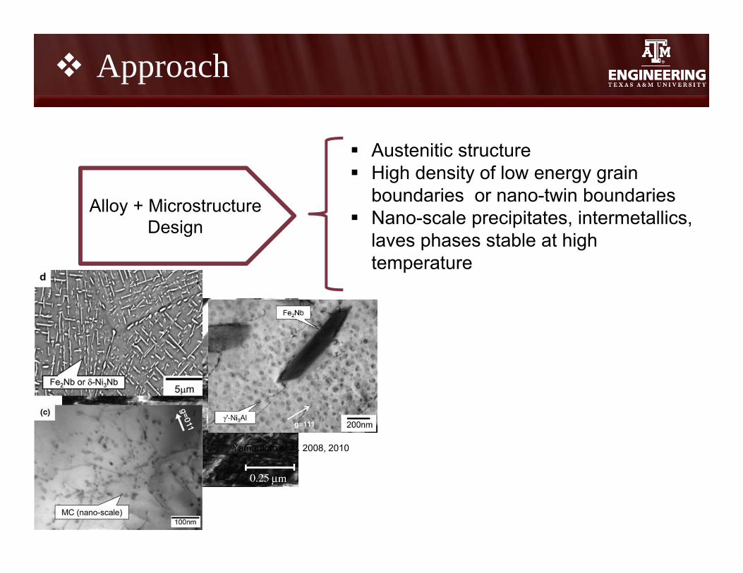
Alloy + MicrostructureDesign
Austenitic structure High density of low energy grain boundaries or
nano-twin boundaries Nano-scale precipitates, intermetallics, laves
phases stable at high temperature Formation of alumina surface oxide

Strategy—Computer-Aided Alloy Design
3
Optimization of micro-alloying additions for desired microstructure and given performance criteria: Single bulk phase, i.e. austenite Control SFE and enhanced twinning ability Alumina formation Dissolvable carbides/carbonitrides (welding issue?) MC instead of M23C6
High temperature intermetallics and laves phases Very fine particles (control MC size with Nb, Ti, Zr, V, etc., nucleation at
dislocations and twin boundaries)
Prediction of alumina-scale forming ability
Prediction of twinning ability
Transformation kinetics of precipitate phases
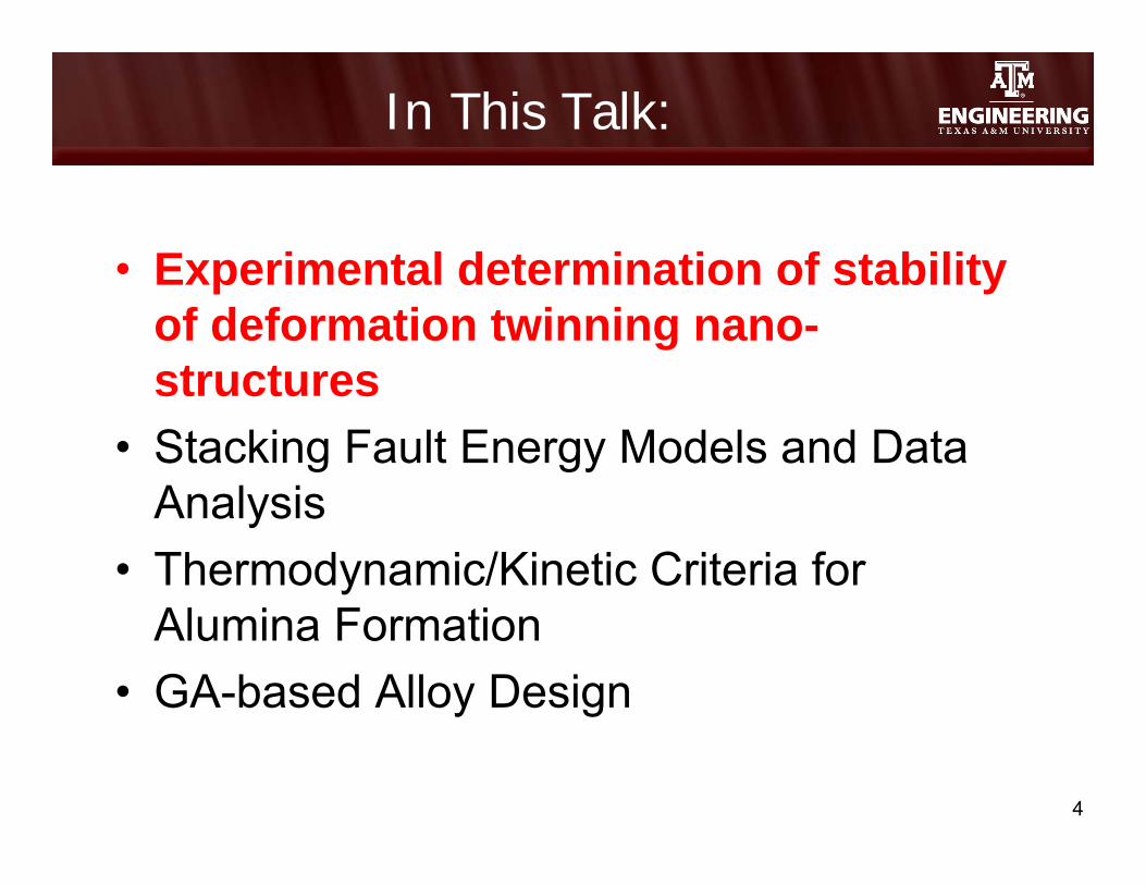
In This Talk:
• Experimental determination of stability of deformation twinning nano-structures
• Stacking Fault Energy Models and Data Analysis
• Thermodynamic/Kinetic Criteria for Alumina Formation
• GA-based Alloy Design
4

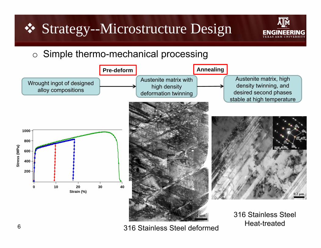
Strategy--Microstructure Design
5
o Twinning induced Grain Boundary Engineering (GBE)
Effects of pre-strain and annealing temperatureon the frequency of CSL boundaries inthermomechanically processed 321 austeniticstainless steel, cited from Kurihara et al.
ReferencesLin, P., G. Palumbo, U. Erb, and K. Aust, Scripta Materialia, 1995. 33(9): p. 1387-1392.Kurihara, K., H. Kokawa, S. Sato, Y. Sato, H. Fujii, and M. Kawai, Journal of Materials Science, 2011: p. 1-6.
How about nano-scale deformation twins?
Deformation twinning induced GBE?
Strategy--Microstructure Design
6
o Simple thermo-mechanical processing
Wrought ingot of designed alloy compositions
Austenite matrix with high density
deformation twinning
Austenite matrix, high density twinning, and
desired second phases stable at high temperature
Pre-deform Annealing
316 Stainless Steel deformed
1000
800
600
400
200
Stre
ss (M
Pa)
403020100Strain (%)
316 Stainless SteelHeat-treated

Questions and Challenges
7
o Fundamental study of recovery and recrystallization (ReX) of deformation twins in low SFE steels in the presence of various densities of dislocations. o In polycrystal of 316 SS
o Role of in-situ carbides and nitrides of Ta, V, W, Cr during recovery and ReX in the presence of deformation twins? What is the optimum thermo-mechanical processing path?
o Control of particle size and distribution with micro-alloying control
o Multi-objective alloy optimization using genetic algorithms
o The role of deformation twins, laves phases, nano carbides, and intermetallic particles on creep and stress rupture behavior of designed steels.

Materials studied so far
8
Alloy 1
Fully austenite
Uncontrollable NbC precipitation
No Twinning (by our own exp.)
Alumina scale formation
Alloy 2 Second phase formation
Uncontrollable Ti-rich NbCprecipitation
Alloy 3
Austenite with intra-granular second phase
Uncontrollable Ti-Nb carbo-nitrides and AlN precipitation
all in wt% Fe Ni Cr Mn Nb Si Al Ti Mo V C N B
Alloy 1 Ba. 20 14 2 0.86 0.15 2.5 0 2.5 0 0.08 0 0.01
Alloy 2 Ba. 12 14 10 1 0.2 2.5 0.3 2.5 0.5 0.08 0.01 0
Alloy 3 Ba. 17 14 10 1 0.2 2.5 0.3 2.5 0.5 0.08 0.01 0
Alloys selected based on literatureHadfield
Steel
Highly twinned {001}/{111} texture
Evolution of second phase at high temperatures
316N SS
Fully austenite
No twinning
316 SS
Fully austenite
Twinning
No alumina scale formation
Study: deformation-twin thermal stability and their effect on recrystallization and grain boundary character distribution
800
600
400
200
True
Str
ess
(Mpa
)
3020100Strain (%)
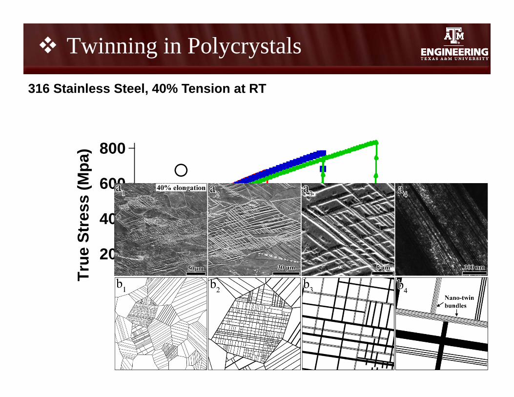
Twinning in Polycrystals
316 Stainless Steel, 40% Tension at RT

800
600
400
200
True
Str
ess
(Mpa
)
3020100Strain (%)
Twinning in Polycrystals
10
316 Stainless Steel, Tension at RT
20% 30% 40%
Grains with twins (%) 62.6±4.6 77.3±3.1 79.5±4.3

Twin Thermal Stability During In-situ TEM Heating
11
316 Stainless Steel, Strained 20%
RTBF DF of Twins
470℃
900℃
~15 minutes
~18 minutes
~35 minutes
~36 minutes
~37 minutes
1000℃
1000℃
1000℃
Twin Thermal Stability
12
316 Stainless Steel, Tension at RT
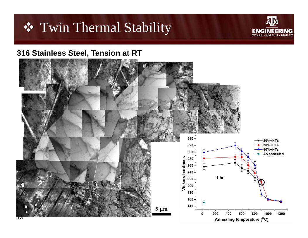
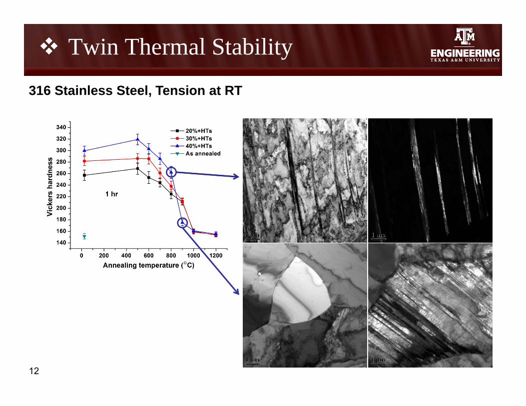
Twin Thermal Stability
13
316 Stainless Steel, Tension at RT
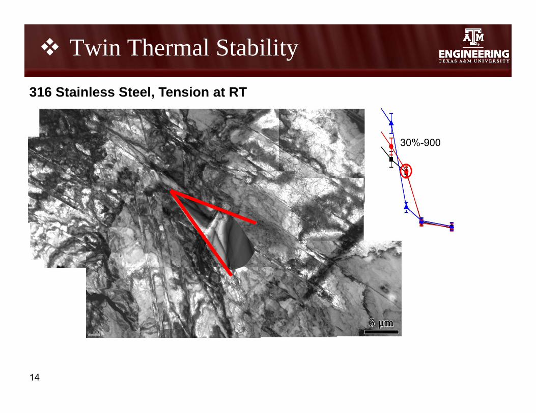
Twin Thermal Stability
14
316 Stainless Steel, Tension at RT
30%-900
Twinnability: Summary & Future Work
15
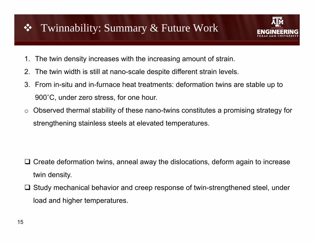
1. The twin density increases with the increasing amount of strain.
2. The twin width is still at nano-scale despite different strain levels.
3. From in-situ and in-furnace heat treatments: deformation twins are stable up to
900˚C, under zero stress, for one hour.
o Observed thermal stability of these nano-twins constitutes a promising strategy for
strengthening stainless steels at elevated temperatures.
Create deformation twins, anneal away the dislocations, deform again to increase
twin density.
Study mechanical behavior and creep response of twin-strengthened steel, under
load and higher temperatures.

In This Talk:
• Experimental determination of stability of deformation twinning nano-structures
• Stacking Fault Energy Models and Data Analysis
• Thermodynamic/Kinetic Criteria for Alumina Formation
• GA-based Alloy Design
16
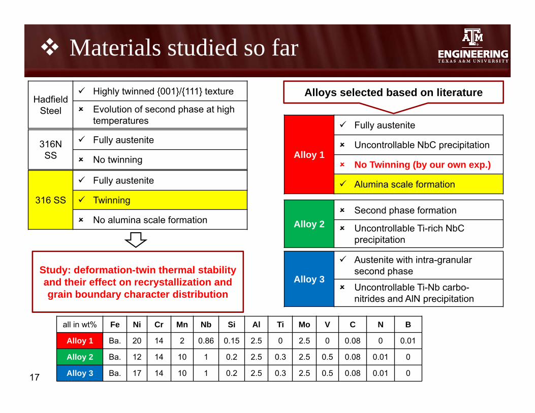
Materials studied so far
17
Alloy 1
Fully austenite
Uncontrollable NbC precipitation
No Twinning (by our own exp.)
Alumina scale formation
Alloy 2 Second phase formation
Uncontrollable Ti-rich NbCprecipitation
Alloy 3
Austenite with intra-granular second phase
Uncontrollable Ti-Nb carbo-nitrides and AlN precipitation
all in wt% Fe Ni Cr Mn Nb Si Al Ti Mo V C N B
Alloy 1 Ba. 20 14 2 0.86 0.15 2.5 0 2.5 0 0.08 0 0.01
Alloy 2 Ba. 12 14 10 1 0.2 2.5 0.3 2.5 0.5 0.08 0.01 0
Alloy 3 Ba. 17 14 10 1 0.2 2.5 0.3 2.5 0.5 0.08 0.01 0
Alloys selected based on literatureHadfield
Steel
Highly twinned {001}/{111} texture
Evolution of second phase at high temperatures
316N SS
Fully austenite
No twinning
316 SS
Fully austenite
Twinning
No alumina scale formation
Study: deformation-twin thermal stability and their effect on recrystallization and grain boundary character distribution

18
Prediction of Stacking Fault Energy as a Function of Alloying Additions
Martensitetransformation
Mechanical Twinning
Cross-Slip
Low
High
SFE
Effects on SFE: Prediction:
Relevant to creep, strain deformation, annealing twins, formation of dislocations, stress corrosion cracking, phase transformation stability, and electron/vacancy density, but we want to optimize SFE to ensure formation of deformation twins
Models:
Experimental Measurements• (A. Dumay 2006)• (Schramm 1975)• (Xing Tian 2008)• Many more
Theoretical Predictions• (Cohen 1976)• (Mullner 1998)• (Jacques 2010)• (Vitos 2011)• (Q. Lu 2013)• (K. Ishida 1976)• Many more
1. Alloying elements
2. Temperature3. Interstitials
19
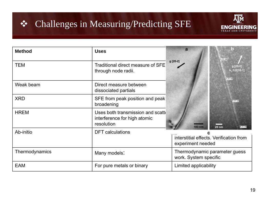
Method Uses Drawbacks
TEM Traditional direct measure of SFE through node radii.
Systematic error. Imagecorrections. Idealized dislocation. Low SFE materials (<40 mJ/M^2)
Weak beam Direct measure between dissociated partials
Systematic error. Laborious method. Low SFE more suitable
XRD SFE from peak position and peak broadening
Indirect method. Needs to use standard reference samples.
HREM Uses both transmission and scatter interference for high atomic resolution
Thin foil sample may introduce surface effects. Sensitive to noise and aberrations.
Ab-initio DFT calculations Limited system size. Contradictoryinterstitial effects. Verification from experiment needed
Thermodynamics Many models: Thermodynamic parameter guess work. System specific
EAM For pure metals or binary Limited applicability
Challenges in Measuring/Predicting SFE
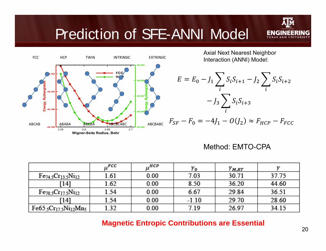
Prediction of SFE-ANNI Model
20
Axial Next Nearest Neighbor Interaction (ANNI) Model:
4
Method: EMTO-CPA
Magnetic Entropic Contributions are Essential

Prediction of SFE – Ab Initio Lattice Deformations
21
[Jahnatek et al PRB 2009]
Pure Fe

Incorporation of SFE into alloy design is essential
• Many attempts from literature to formulate temperature and alloyingeffect on SFE, from experiment and from theory, have had limited success
– “Until today, no generally accepted method for the SFE calculation exists that can be applied to a wide range of chemical compositions” (Saeed-Akbari, 2013)
– high error of uncertainty- values reported in the 1960’s and early 1970s are, in general 20-30% overestimated (Campos, 2008)
– “In summary, there is no agreement on accuracy of SFE values obtained, and perhaps no better than about 20 pct” (Siems et al)
– Theoretical big discrepancy with carbon effect (either no effect or huge effect)- relaxation time for carbon diffusion, and how carbon interacts with the SF
– “The dependence of the SFE on…carbon…is not yet fully understood, and different tendencies have been found by different authors” (Mujica 2012)
22
Stacking Fault Energy -Challenges

23
Database Builder
Data Mining Approach (SFE)
Records
Composition 1
Dataset B – Properties, Method of determinationComposition 2
Dataset A – Properties,Method of determination
Modular software design Data capture Analysis
• Neural Network• Ab-initio
• Adaptable• Efficient• High throughput
• User input• Automated• Theoretical• Experiment

24
Data Mining Approach (SFE)
Theoretical
Experimental
Examples - SFE trends based on preliminary literature Experimental/Theoretical data
(Yonezawa 2013)
(Vitos 2006)
T = 300 K
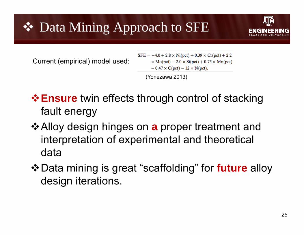
Ensure twin effects through control of stacking fault energy
Alloy design hinges on a proper treatment and interpretation of experimental and theoretical data
Data mining is great “scaffolding” for future alloy design iterations.
25
Data Mining Approach to SFE
(Yonezawa 2013)
Current (empirical) model used:
In This Talk:
• Experimental determination of stability of deformation twinning nano-structures
• Stacking Fault Energy Models and Data Analysis
• Thermodynamic/Kinetic Criteria for Alumina Formation
• GA-based Alloy Design
26

Materials studied so far
27
Alloy 1
Fully austenite
Uncontrollable NbC precipitation
No Twinning (by our own exp.)
Alumina scale formation
Alloy 2 Second phase formation
Uncontrollable Ti-rich NbCprecipitation
Alloy 3
Austenite with intra-granular second phase
Uncontrollable Ti-Nb carbo-nitrides and AlN precipitation
all in wt% Fe Ni Cr Mn Nb Si Al Ti Mo V C N B
Alloy 1 Ba. 20 14 2 0.86 0.15 2.5 0 2.5 0 0.08 0 0.01
Alloy 2 Ba. 12 14 10 1 0.2 2.5 0.3 2.5 0.5 0.08 0.01 0
Alloy 3 Ba. 17 14 10 1 0.2 2.5 0.3 2.5 0.5 0.08 0.01 0
Alloys selected based on literatureHadfield
Steel
Highly twinned {001}/{111} texture
Evolution of second phase at high temperatures
316N SS
Fully austenite
No twinning
316 SS
Fully austenite
Twinning
No alumina scale formation
Study: deformation-twin thermal stability and their effect on recrystallization and grain boundary character distribution
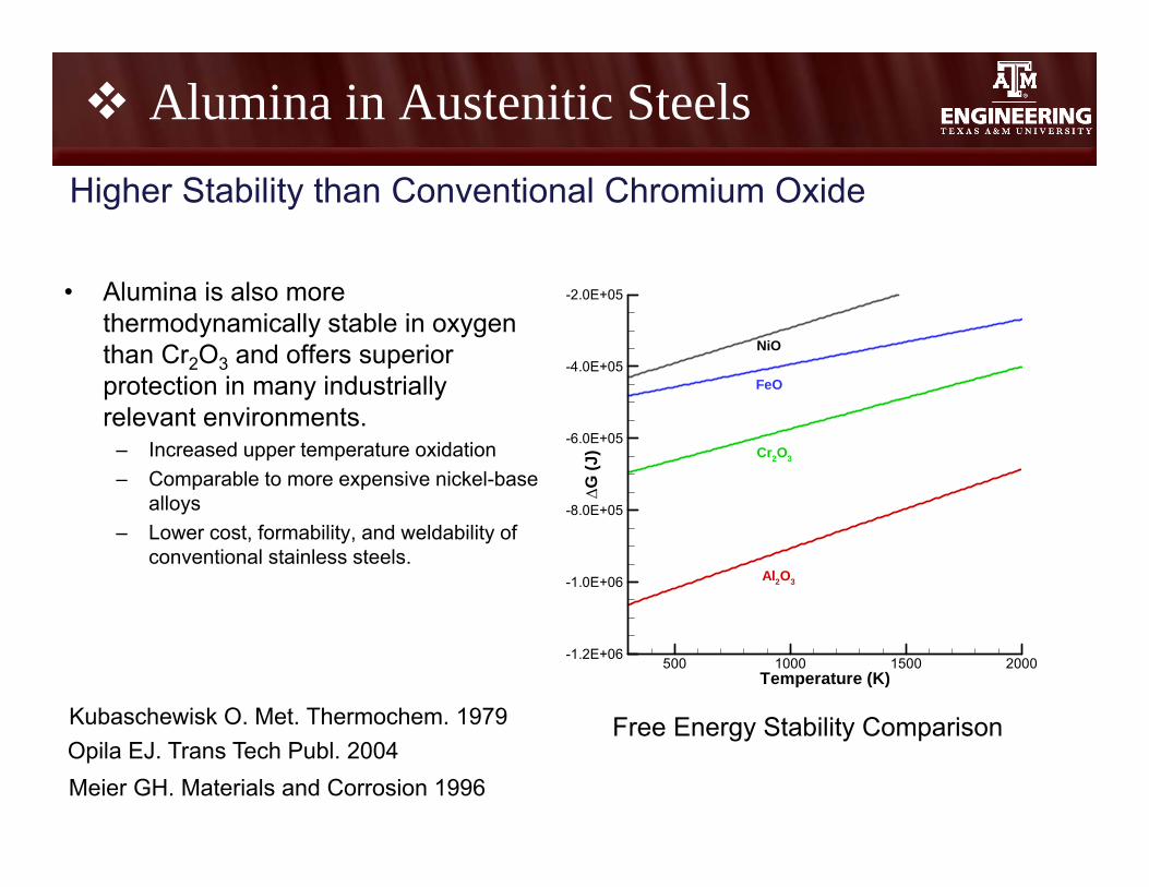
• Alumina is also more thermodynamically stable in oxygen than Cr2O3 and offers superior protection in many industrially relevant environments.
– Increased upper temperature oxidation – Comparable to more expensive nickel-base
alloys – Lower cost, formability, and weldability of
conventional stainless steels.
Opila EJ. Trans Tech Publ. 2004Meier GH. Materials and Corrosion 1996
Higher Stability than Conventional Chromium Oxide
Free Energy Stability Comparison
Alumina in Austenitic Steels
Kubaschewisk O. Met. Thermochem. 1979
Temperature (K)
G(J
)
500 1000 1500 2000-1.2E+06
-1.0E+06
-8.0E+05
-6.0E+05
-4.0E+05
-2.0E+05
Al2O3
Cr2O3
FeO
NiO
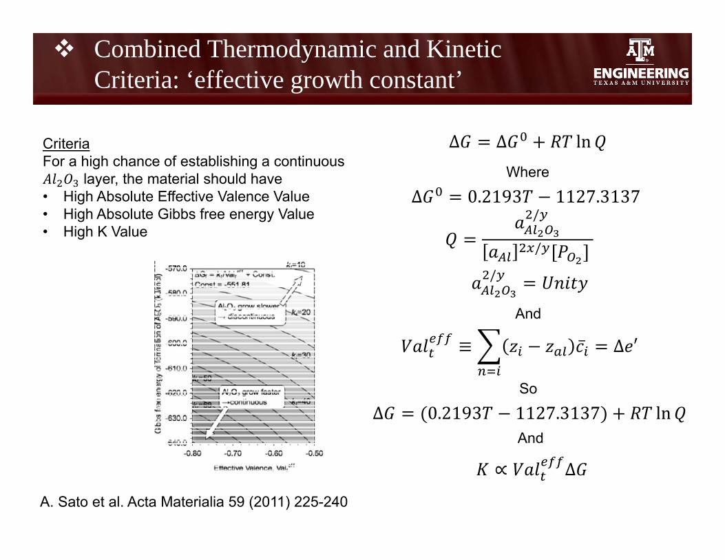
Δ Δ ln
Δ 0.2193 1127.3137
∝ ∆
Δ 0.2193 1127.3137 lnSo
Where
/
/
And
And
/
CriteriaFor a high chance of establishing a continuous
layer, the material should have• High Absolute Effective Valence Value• High Absolute Gibbs free energy Value• High K Value
≡ ̅ ∆ ′
A. Sato et al. Acta Materialia 59 (2011) 225-240
Combined Thermodynamic and Kinetic Criteria: ‘effective growth constant’
Effective Valence (Veff)
Free
Ener
gy(
G)
-0.58 -0.56 -0.54 -0.52 -0.5-1246
-1245
-1244
-1243
-1242
-1241
-1240 700692684676668660652644636628620612604596588580572564556548540532524516508500
K Value
+Cr
+Ni
-Al
-Cr
-Ni
+Al
-Nb
+Nb+Mo -Mo
-Mn
+Mn +Si
-Si
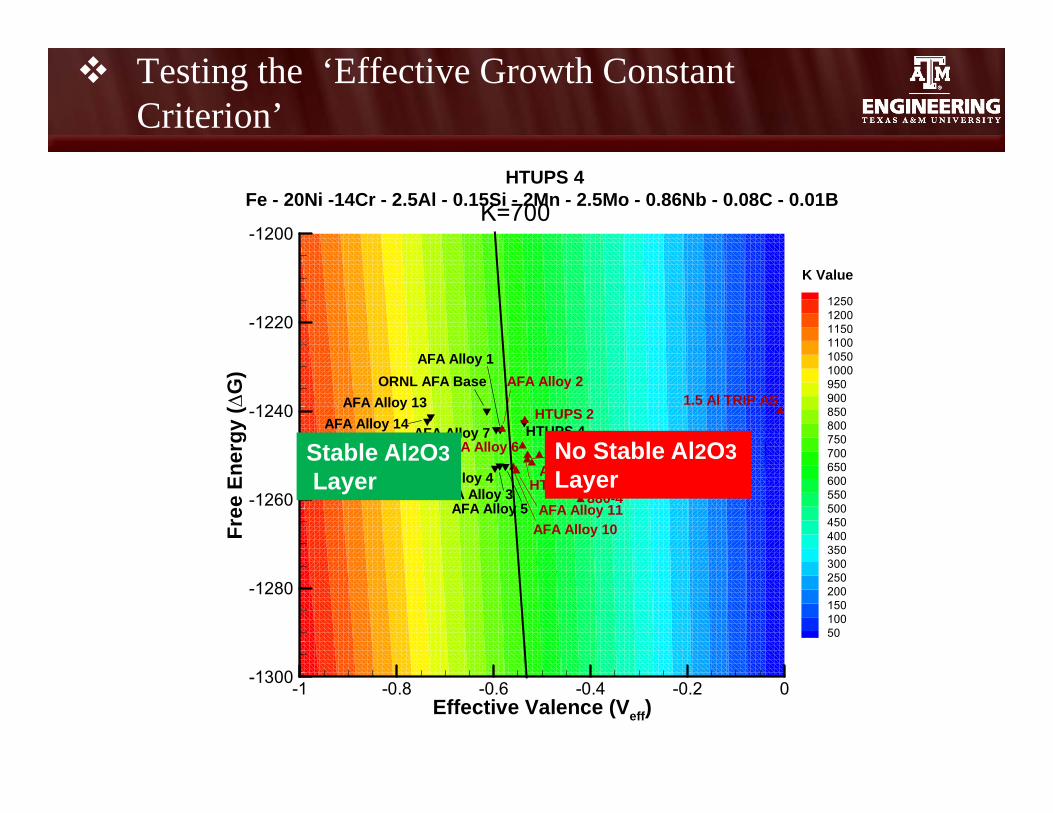
Testing the ‘Effective Growth Constant Criterion’
Effective Valence (Veff)
Free
Ener
gy(
G)
-1 -0.8 -0.6 -0.4 -0.2 0-1300
-1280
-1260
-1240
-1220
-1200
12501200115011001050100095090085080075070065060055050045040035030025020015010050
1.5 Al TRIP AS
880-4
HTUPS 2HTUPS 4
AFA Alloy 8
HTUPS 3
AFA Alloy 6
AFA Alloy 2AFA Alloy 13
ORNL AFA BaseAFA Alloy 1
AFA Alloy 3
K Value
AFA Alloy 4
AFA Alloy 5
AFA Alloy 9
AFA Alloy 10AFA Alloy 11
AFA Alloy 12
AFA Alloy 14 AFA Alloy 7
HTUPS 4Fe - 20Ni -14Cr - 2.5Al - 0.15Si - 2Mn - 2.5Mo - 0.86Nb - 0.08C - 0.01BK=700
Stable Al2O3Layer
No Stable Al2O3Layer
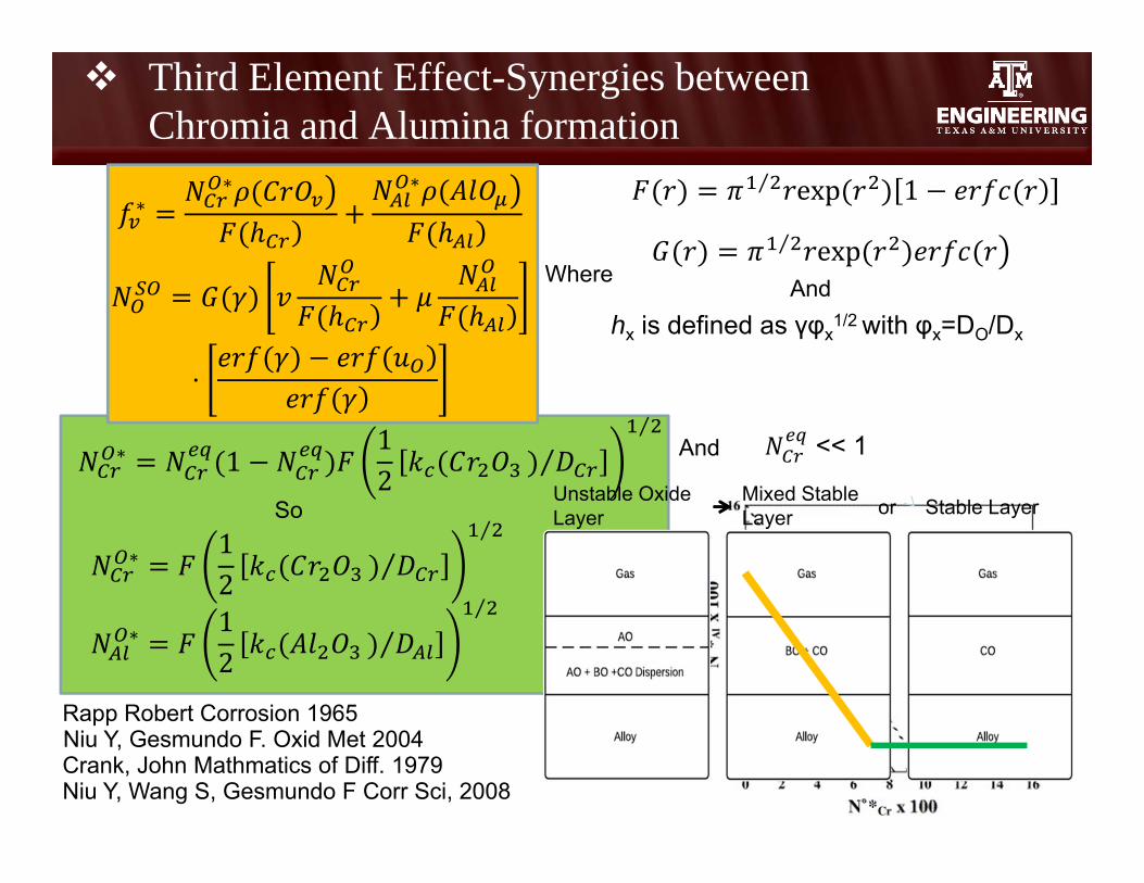
∗∗ ∗ ⁄ exp 1
∗ 12
⁄⁄
∗ 12
⁄⁄
So
Where
⋅
And
And
⁄ exp
∗ 112
⁄⁄
hx is defined as γφx1/2 with φx=DO/Dx
Niu Y, Gesmundo F. Oxid Met 2004
Third Element Effect-Synergies between Chromia and Alumina formation
Crank, John Mathmatics of Diff. 1979Niu Y, Wang S, Gesmundo F Corr Sci, 2008
Rapp Robert Corrosion 1965
<< 1
Stable LayerMixed Stable Layer
Unstable Oxide Layer or

Third Element Effect Predominance Maps
Stable LayerMixed Stable Layer
Unstable Oxide Layer or
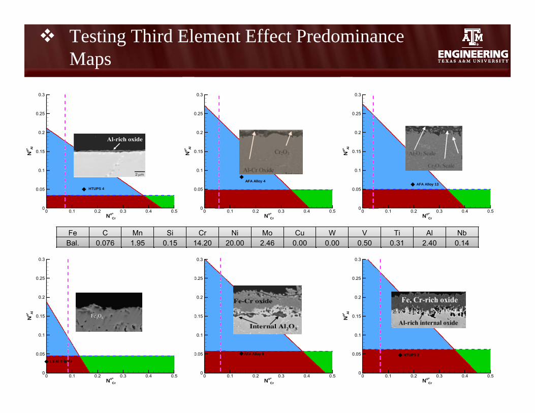
No*Cr
No* Al
0 0.1 0.2 0.3 0.4 0.50
0.05
0.1
0.15
0.2
0.25
0.3
AFA Alloy 9
No*Cr
No* Al
0 0.1 0.2 0.3 0.4 0.50
0.05
0.1
0.15
0.2
0.25
0.3
HTUPS 4
No*Cr
No* Al
0 0.1 0.2 0.3 0.4 0.50
0.05
0.1
0.15
0.2
0.25
0.3
AFA Alloy 4
No*Cr
No* Al
0 0.1 0.2 0.3 0.4 0.50
0.05
0.1
0.15
0.2
0.25
0.3
AFA Alloy 13
No*Cr
No* Al
0 0.1 0.2 0.3 0.4 0.50
0.05
0.1
0.15
0.2
0.25
0.3
1.5 Al Trip As
No*Cr
No* Al
0 0.1 0.2 0.3 0.4 0.50
0.05
0.1
0.15
0.2
0.25
0.3
HTUPS 2
Fe C Mn Si Cr Ni Mo Cu W V Ti Al NbBal. 0.075 1.95 0.15 14.19 19.95 2.46 0 0 0.00 0.00 2.48 0.86Fe C Mn Si Cr Ni Mo Cu W V Ti Al Nb
Bal. 0.209 2.00 0.14 13.97 25.03 1.99 0.52 0.96 0.05 0.05 4.11 1.01Fe C Mn Si Cr Ni Mo Cu W V Ti Al Nb
Bal. 0.016 0.15 0.13 18.72 32.8 0.15 0.15 0.14 0.05 0.05 3.08 3.27Fe C Mn Si Cr Ni Mo Cu W V Ti Al Nb
Bal. 0.110 1.55 0.06 0.00 0.00 0.00 0.00 0.00 0.00 0.00 1.50 0.00Fe C Mn Si Cr Ni Mo Cu W V Ti Al Nb
Bal. 0.171 4.99 0.13 13.84 12.08 0.15 3.04 0.15 0.05 0.05 2.52 1.03Fe C Mn Si Cr Ni Mo Cu W V Ti Al Nb
Bal. 0.076 1.95 0.15 14.20 20.00 2.46 0.00 0.00 0.50 0.31 2.40 0.14
Testing Third Element Effect Predominance Maps
In This Talk:
• Experimental determination of stability of deformation twinning nano-structures
• Stacking Fault Energy Models and Data Analysis
• Thermodynamic/Kinetic Criteria for Alumina Formation
• GA-based Alloy Design
34
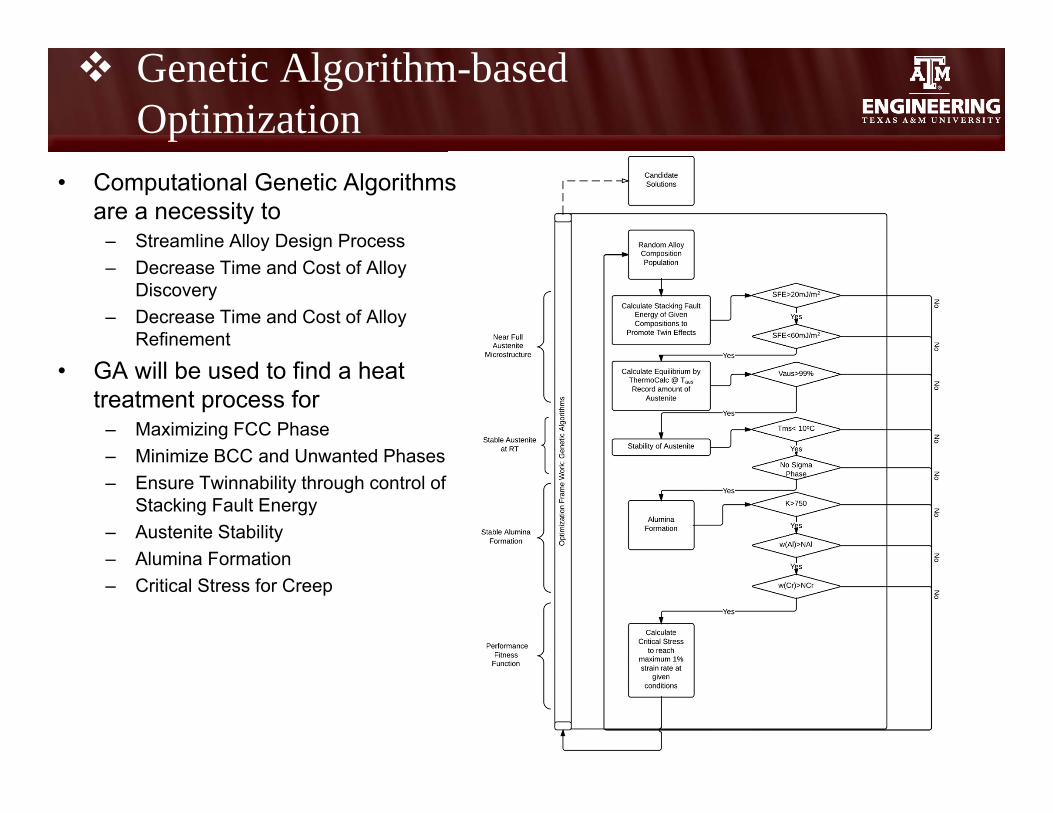
Genetic Algorithm-based Optimization
• Computational Genetic Algorithms are a necessity to
– Streamline Alloy Design Process– Decrease Time and Cost of Alloy
Discovery – Decrease Time and Cost of Alloy
Refinement
• GA will be used to find a heat treatment process for
– Maximizing FCC Phase – Minimize BCC and Unwanted Phases– Ensure Twinnability through control of
Stacking Fault Energy– Austenite Stability– Alumina Formation– Critical Stress for Creep
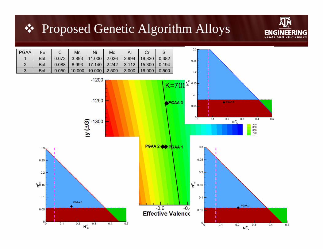
Proposed Genetic Algorithm AlloysPGAA Fe C Mn Ni Mo Al Cr Si
1 Bal. 0.073 3.893 11.000 2.026 2.994 19.820 0.3822 Bal. 0.088 8.993 17.140 2.242 3.112 15.300 0.1943 Bal. 0.050 10.000 10.000 2.500 3.000 16.000 0.500
K=700
No*Cr
No* Al
0 0.1 0.2 0.3 0.4 0.50
0.05
0.1
0.15
0.2
0.25
0.3
PGAA 3
No*Cr
No* A
l
0 0.1 0.2 0.3 0.4 0.50
0.05
0.1
0.15
0.2
0.25
0.3
PGAA 2
No*Cr
No* Al
0 0.1 0.2 0.3 0.4 0.50
0.05
0.1
0.15
0.2
0.25
0.3
PGAA 1
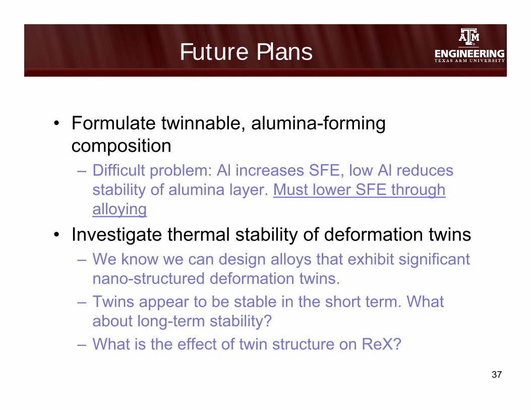
Future Plans
• Formulate twinnable, alumina-forming composition– Difficult problem: Al increases SFE, low Al reduces
stability of alumina layer. Must lower SFE through alloying
• Investigate thermal stability of deformation twins– We know we can design alloys that exhibit significant
nano-structured deformation twins. – Twins appear to be stable in the short term. What
about long-term stability?– What is the effect of twin structure on ReX?
37

Future Plans, ctd
• Investigate effect of nano-precipitates– How do nano-precipitates interact with twins?
• Comprehensive Alloy Optimization:– Alumina, twinnability, nano-precipitates– Prepare alloys, characterize mechanical response,
long-term behavior
38
Backup slides
Approach
40
Alloy + MicrostructureDesign
Austenitic structure High density of low energy grain
boundaries or nano-twin boundaries Nano-scale precipitates, intermetallics,
laves phases stable at high temperature
Yamamoto et al. 2008, 2010
Approach
41
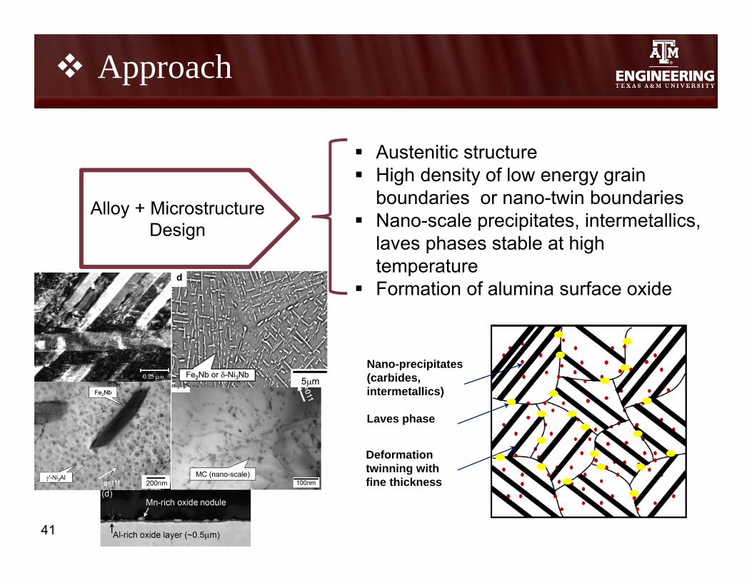
Alloy + MicrostructureDesign
Austenitic structure High density of low energy grain
boundaries or nano-twin boundaries Nano-scale precipitates, intermetallics,
laves phases stable at high temperature
Formation of alumina surface oxide
Nano-precipitates (carbides, intermetallics)
Laves phase
Deformation twinning with fine thickness
42
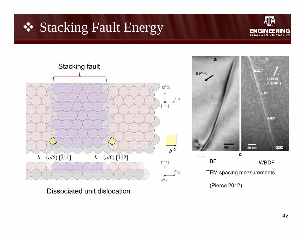
Stacking Fault Energy
Dissociated unit dislocation
Stacking fault
BF WBDF
TEM spacing measurements
(Pierce 2012)

43
Transmission Electron Microscope• Direct observation of faulted
dislocation structures– Dislocation nodes– Multiple ribbons– Stacking fault tetrahedral– Faulted dipoles
X-ray Diffraction• Research by Reed and Schramm- established relationship among stacking
fault probability and microstrain– Stacking faults affect XRD line shift and line broadening– In-situ XRD: SFE determined from critical shear stress (David Rafaja, 2013)
Others: • HREM, Texture, Creep
Measuring SFE
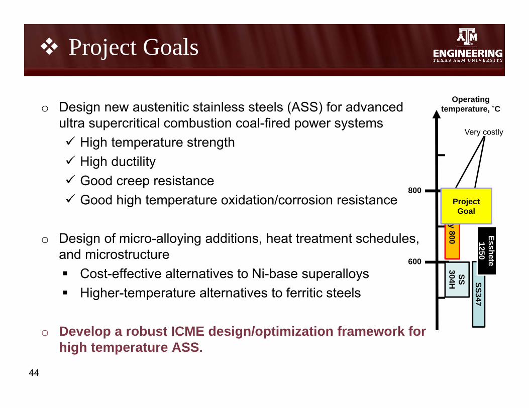
Project Goals
o Design new austenitic stainless steels (ASS) for advanced ultra supercritical combustion coal-fired power systems High temperature strength High ductility Good creep resistance Good high temperature oxidation/corrosion resistance
o Design of micro-alloying additions, heat treatment schedules, and microstructure Cost-effective alternatives to Ni-base superalloys Higher-temperature alternatives to ferritic steels
o Develop a robust ICME design/optimization framework for high temperature ASS.
44
800
600
Operating temperature, ˚C
SS304H SS347
Alloy 800 Esshete
1250N
F 709
Very costly
Project Goal
45
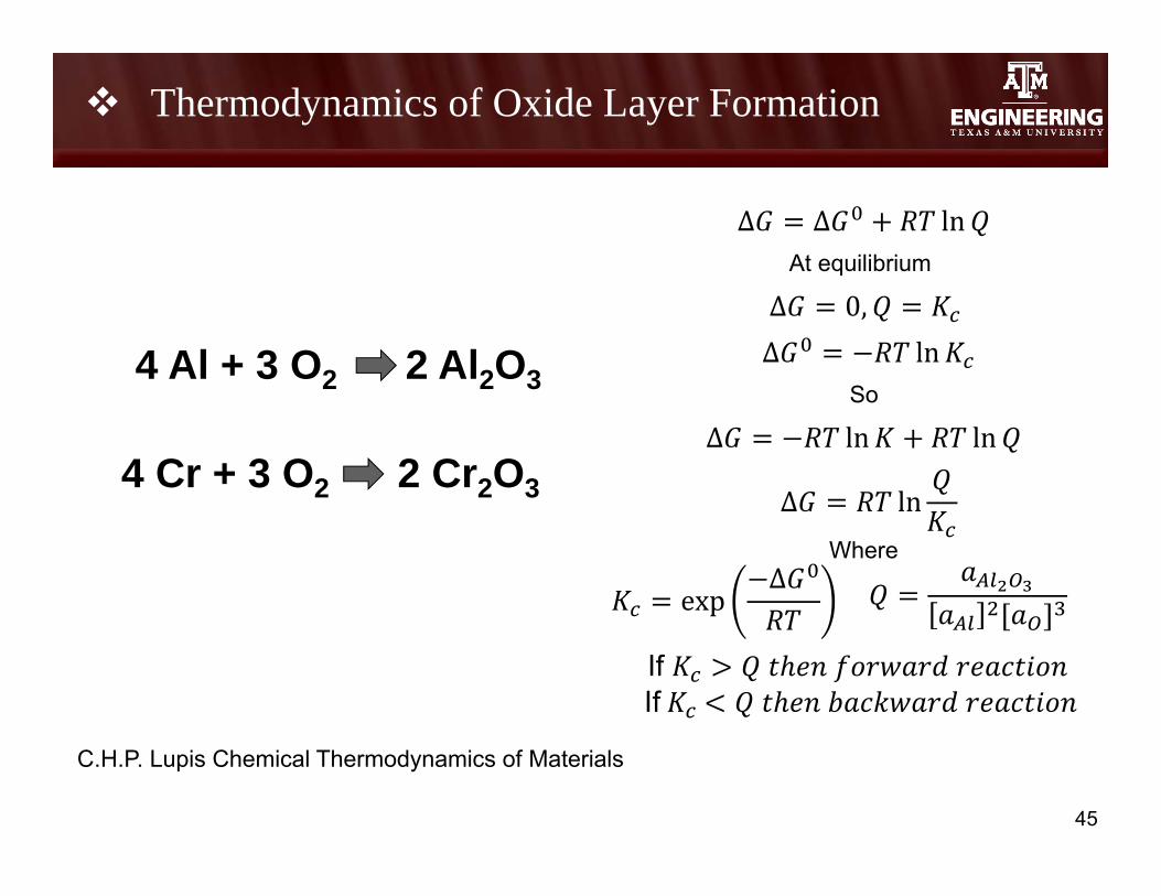
C.H.P. Lupis Chemical Thermodynamics of Materials
4 Al + 3 O2 2 Al2O3
Δ Δ ln
Δ 0,At equilibrium
Δ ln
expΔ
Δ ln lnSo
Δ lnWhere
4 Cr + 3 O2 2 Cr2O3
If If
Thermodynamics of Oxide Layer Formation