Award BIOS Setup - ELHVB, motherboard information and ... 3.pdf · Chapter 3 Award BIOS Setup 45...
40
42 SBC-776 User Manual 3 Award BIOS Setup This chapter describes how to configure the BIOS for the system. CHAPTER
Transcript of Award BIOS Setup - ELHVB, motherboard information and ... 3.pdf · Chapter 3 Award BIOS Setup 45...

42 SBC-776 User Manual
3Award BIOS Setup
This chapter describes how to configurethe BIOS for the system.
CH
AP
TE
R

Chapter 3 Award BIOS Setup 43
Starting setupThe Award BIOS is immediately activated when you first turn onthe computer. The BIOS reads system configuration information inCMOS RAM and begins the process of checking out the systemand configuring it through the power-on self test (POST).
When these preliminaries are finished, the BIOS seeks an operatingsystem on one of the data storage devices (hard drive, floppy drive,etc.). The BIOS launches the operating system and hands control ofsystem operations to it.
During POST, you can start the Setup program in one of two ways:1.By pressing Del immediately after switching the system on, or2.By pressing Del or pressing Ctrl-Alt-Esc when the followingmessage appears briefly at the bottom of the screen during POST:
TO ENTER SETUP BEFORE BOOT PRESS DEL KEY
If the message disappears before you respond and you still wish toenter Setup, restart the system to try again by turning it OFF thenON or pressing the RESET button on the system case. You mayalso restart by simultaneously pressing Ctr-Alt-Del. If you do notpress the keys at the correct time and the system does not boot, anerror message appears and you are again asked to
PRESS F1 TO CONTINUE, DEL TO ENTER SETUP

44 SBC-776 User Manual
Setup keysThese keys helps you navigate in Award BIOS:
Up arrow Move to previous itemDown arrow Move to next itemLeft arrow Move to the item in the left handRight arrow Move to the item in the right handEsc Main Menu: Quit and not save changes into CMOS RAM
Other pages: Exit current page and return to Main MenuPgUP/+ Increase the numeric value or make
changesPgDn/- Decrease the numeric value or make
changesF1 General help, only for Status Page Setup
Menu and Option Page Setup MenuF2 Item HelpF3 ReservedF4 ReservedF5 Restore the previous CMOS value from
CMOS, only for Option Page Setup MenuF6 Load the default CMOS RAM value from
BIOS default table, only for Option PageSetup Menu
F7 Load the defaultF8 ReservedF9 ReservedF10 Save all the CMOS changes, only for Main
Menu

Chapter 3 Award BIOS Setup 45
Getting helpPress F1 to pop up a small help window that describes the appro-priate keys to use and the possible selections for the highlighteditem. To exit the Help Window press Esc or the F1 key again.
In Case of Problems
If, after making and saving system changes with Setup, youdiscover that your computer no longer is able to boot, the AwardBIOS supports an override to the CMOS settings that resets yoursystem to its default configuration.
You can invoke this override by immediately pressing Insert; whenyou restart your computer. You can restart by either using the ON/OFF switch, the RESET button or by pressing Ctrl-Alt-Delete.
The best advice is to alter only settings that you thoroughlyunderstand. In particular, do not change settings in the Chipsetscreen without a good reason. The Chipset defaults have beencarefully chosen by Award Software or your system manufacturerfor the best performance and reliability. Even a seemingly smallchange to the Chipset setup may cause the system to becomeunstable.

46 SBC-776 User Manual
Main Setup Menu
Standard CMOS FeaturesUse this menu for basic system configuration. (Date, time, IDE,
etc.)
Advanced BIOS FeaturesUse this menu to set the advanced features available on your
system.
Advanced Chipset FeaturesUse this menu to change the values in the chipset registers and
optimize your system’s performance.
Integrated PeripheralsUse this menu to specify your settings for integrated peripherals.
(Primary slave, secondary slave, keyboard, mouse etc.)
Power Management SetupUse this menu to specify your settings for power management.
(HDD power down, power on by ring, KB wake up, etc.)

Chapter 3 Award BIOS Setup 47
PnP/PCI ConfigurationThis entry appears is your system supports PnP/PCI.
PC Health StatusThis menu allows you to set the shutdown temperature for yoursystem.
Frequency/Voltage ControlUse this menu to specify your settings for frequency/ voltagecontrol.
Load Fail-Safe DefaultsUse this menu to load the BIOS default values for the minimal/stable performance for your system to operate.
Load Optimized DefaultsUse this menu to load the BIOS default values that are factorysettings for optimal performance system operations. WhileAWARD has designated the custom BIOS to maximize perfor-mance, the factory has the right to change these defaults to meettheir needs.
Set Supervisor/User PasswordUse this menu to set User and Supervisor Passwords.
Save and Exit SetupSave CMOS value changes to CMOS and exit setup.
Exit Without SavingAbandon all CMOS value changes and exit setup.

48 SBC-776 User Manual
Standard CMOS Features
This standard setup menu allows users to configure systemcomponents such as the date, time, hard disk drive, floppy drive,display, and memory. Online help for each field can be accessedby pressing F1.
Date and Time ConfigurationThe BIOS determines the day of the week from the other dateinformation. This field is for information only.
Press the left or right arrow key to move to the desired field (date,month, year). Press the PgUp/- or PgDn/+ key to increment thesetting, or type the desired value into the field.
The time format is based on the 24-hour military-time clock. Forexample, 1 p.m. is 13:00:00 hours. Press the left or right arrow keyto move to the desired field. Press the PgUp/- or PgDn/+ key toincrement the setting, or type the desired value into the field.
HARD DISKSThe BIOS supports up to four IDE drives. This section does notshow information about other IDE devices, such as a CD-ROMdrive, or about other hard drive types, such as SCSI drives.
NOTE: We recommend that you select type AUTO for all drives.

Chapter 3 Award BIOS Setup 49
If you do not want to select drive type AUTO, other methods ofselecting the drive type are available:
1.Match the specifications of your installed IDE hard drive(s) with the preprogrammed values for drive types 1 through 45.
2.Select USER and enter values into each drive parameter field.
3.Use the IDE HDD AUTO DETECTION function in Setup.
Here is a brief explanation of drive specifications:
Type: The BIOS contains a table of predefined drive types. Each defined drive type has a specified number of cylinders,
number of heads, write precompensation factor, landing zone, and number of sectors. Drives whose specifications do not accommodate any predefined type are classified as type USER.
Size: Disk drive capacity (approximate). Note that this size is usually slightly greater than the size of a formatted disk given by a disk-checking program.
Cyls: Number of cylinders
Head: Number of heads
Precomp: Write precompensation cylinder
Landz: Landing zone
Sector: Number of sectors
Mode: Auto, Normal, Large, or LBA
- Auto: The BIOS automatically determines the optimal mode.
- Normal: Maximum number of cylinders, heads, and sectors supported are 1024, 16, and 63.
- Large: For drives that do not support LBA and have more than 1024 cylinders.
The BIOS can automatically detect the specifications and optimaloperating mode of almost all IDE hard drives. When you selecttype AUTO for a hard drive, the BIOS detects its specifications
50 SBC-776 User Manual
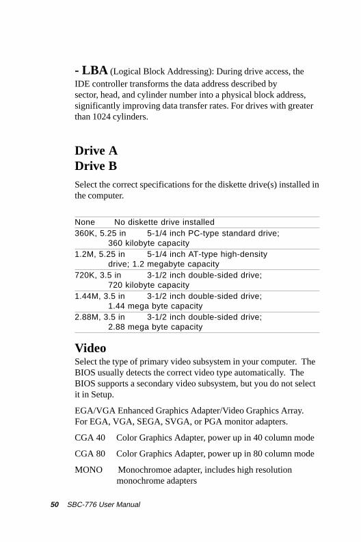
- LBA (Logical Block Addressing): During drive access, theIDE controller transforms the data address described bysector, head, and cylinder number into a physical block address,significantly improving data transfer rates. For drives with greaterthan 1024 cylinders.
Drive ADrive BSelect the correct specifications for the diskette drive(s) installed inthe computer.
None No diskette drive installed360K, 5.25 in 5-1/4 inch PC-type standard drive;
360 kilobyte capacity1.2M, 5.25 in 5-1/4 inch AT-type high-density
drive; 1.2 megabyte capacity720K, 3.5 in 3-1/2 inch double-sided drive;
720 kilobyte capacity1.44M, 3.5 in 3-1/2 inch double-sided drive;
1.44 mega byte capacity2.88M, 3.5 in 3-1/2 inch double-sided drive;
2.88 mega byte capacity
VideoSelect the type of primary video subsystem in your computer. TheBIOS usually detects the correct video type automatically. TheBIOS supports a secondary video subsystem, but you do not selectit in Setup.
EGA/VGA Enhanced Graphics Adapter/Video Graphics Array.For EGA, VGA, SEGA, SVGA, or PGA monitor adapters.
CGA 40 Color Graphics Adapter, power up in 40 column mode
CGA 80 Color Graphics Adapter, power up in 80 column mode
MONO Monochromoe adapter, includes high resolution monochrome adapters

Chapter 3 Award BIOS Setup 51
Halt OnDuring the power-on-self-test (POST), the computer stops if theBIOS detects a hardware error. You can tell the BIOS to ignorecertain errors during POST and continue the boot-up process.These are the selections:
No errors: POST does not stop for any errors.
All errors If : the BIOS detects any nonfatal error, POSTstops and prompts you to take corrective action.
All, But Keyboard : POST does not stop for a keyboarderror, but stops for all other errors
All, But Diskette: POST does not stop for diskette driveerrors, but stops for all other errors.
All, But Disk/Key : POST does not stop for a keyboard ordisk error, but stops for all other errors.
MemoryYou cannot change any values in the Memory fields; they are onlyfor your information. The fields show the total installed randomaccess memory (RAM) and amounts allocated to base memory,extended memory, and other (high) memory. RAM is counted inkilobytes (KB: approximately one thousand bytes) and megabytes(MB: approximately one million bytes).
RAM is the computer's working memory, where the computerstores programs and data currently being used, so they are accessi-ble to the CPU. Modern personal computers may contain up to 64MB, 128 MB, or more.
Base MemoryTypically 640 KB. Also called conventional memory. The DOSoperating system and conventional applications use this area.

52 SBC-776 User Manual
Extended MemoryAbove the 1-MB boundary. Early IBM personal computers couldnot use memory above 1 MB, but current PCs and their softwarecan use extended memory.
Other MemoryBetween 640 KB and 1 MB; often called High memory. DOS mayload, terminate-and-stay-resident (TSR) programs, such as devicedrivers, in this area, to free as much conventional memory aspossible for applications. Lines in your CONFIG.SYS file that startwith LOADHIGH, load programs into high memory.
Chapter 3 Award BIOS Setup 53
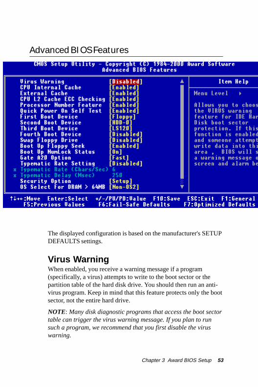
Advanced BIOS Features
The displayed configuration is based on the manufacturer's SETUPDEFAULTS settings.
Virus WarningWhen enabled, you receive a warning message if a program(specifically, a virus) attempts to write to the boot sector or thepartition table of the hard disk drive. You should then run an anti-virus program. Keep in mind that this feature protects only the bootsector, not the entire hard drive.
NOTE: Many disk diagnostic programs that access the boot sectortable can trigger the virus warning message. If you plan to runsuch a program, we recommend that you first disable the viruswarning.

54 SBC-776 User Manual
CPU Internal Cache/External CacheCache memory is additional memory that is much faster thanconventional DRAM (system memory). CPUs from 486-type on upcontain internal cache memory, and most, but not all, modern PCshave additional (external) cache memory. When the CPU requestsdata, the system transfers the requested data from the main DRAMinto cache memory, for even faster access by the CPU.
The External Cache field may not appear if your system does nothave external cache memory.
CPU L2 Cache ECC CheckingWhen you select Enabled, memory checking is enable when theexternal cache contains ECC SRAMs.
Processor Number FeatureThis option is for Pentium III processor. During Enabled, this willcheck the CPU Serial number. Disabled this option if you don'twant the system to know the serial number.
Quick Power On Self TestSelect Enabled to reduce the amount of time required to run thepower-on-self-test (POST). A quick POST skips certain steps. Werecommend that you normally disable quick POST. Better to find aproblem during POST than lose data during your work.
First/Second/Third/Fourth Boot DeviceThe BIOS attempts to load the operating system from the devicesin the sequence selected in these items.
The choices: Floppy, LS/ZIP, HDD, SCSI, CDROM, Disable.

Chapter 3 Award BIOS Setup 55
Swap Floppy DriveThis field is effective only in systems with two floppy drives.Selecting enabled assigns physical drive B to logical drive A, andphysical drive A to logical drive B.
Boot Up Floppy SeekWhen Enabled, the BIOS tests (seeks) floppy drives to determinewhether they have 40 or 80 tracks. Only 360-KB floppy driveshave 40 tracks; drives with 720 KB, 1.2 MB, and 1.44 MBcapacity all have 80 tracks. Because very few modern PCs have40-track floppy drives, we recommend that you set this field toDisabled to save time.
Boot Up NumLock StatusToggle between On or Off to control the state of the NumLock keywhen the system boots. When toggled On, the numeric keypadgenerates numbers instead of controlling cursor operations.
Gate A20 OptionGate A20 refers to the way the system addresses memory above 1MB (extended memory). When set to Fast, the system chipsetcontrols Gate A20. When set to Normal, a pin in the keyboardcontroller controls Gate A20. Setting Gate A20 to Fast improvessystem speed, particularly with OS/2 and Windows.

56 SBC-776 User Manual
Typematic Rate Setting- Key strokes repeat at arate determined by the keyboard controller. Whenenabled, the typematic rate and typematic delay can beselected.
The choice: Enabled/Disabled
Security Option If you have set a password, select whether the password is required every time the System boots, or only when you enter
Setup.
OS Select For DRAM>64MB-Select theoperating system that is running with greater than 64MBor RAM on the system.
The choice: Non-OS2, OS2

Chapter 3 Award BIOS Setup 57
HDD S.M.A.R.T CapabilityHard disk drives have built in problem detectioncapability (Self-Monitoring Analysis and Reporting Technology).If a foreseen problem is about to take place, the computer will
give a you a warning signal. The choice: Enable, Disable
Report No FDD For WIN 95- Reportno FDD for Win 95 or not. The choice: Yes, no

58 SBC-776 User Manual
Advanced Chipset Features
SDRAM CAS Latency TimeWhen synchronous DRAM is installed, the number of clock cycles ofCAS latency depends on the DRAM timing. Do not reset this field from
the default value specified by the system designer.
SDRAM Cycle Time Tras/TrcSelect the number of SCLKs for an access cycle.The choices: 5/7, 7/9 disable.
SDRAM RAS-to-CAS DelayThis field lets you insert a timing delay between the CAS and RAS strobesignals, used when DRAM is written to, read from, or refreshed. Fastgives faster performance; slow gives more stable performance. This fieldapplies only when synchronous DRAM is installed in the system.
Chapter 3 Award BIOS Setup 59
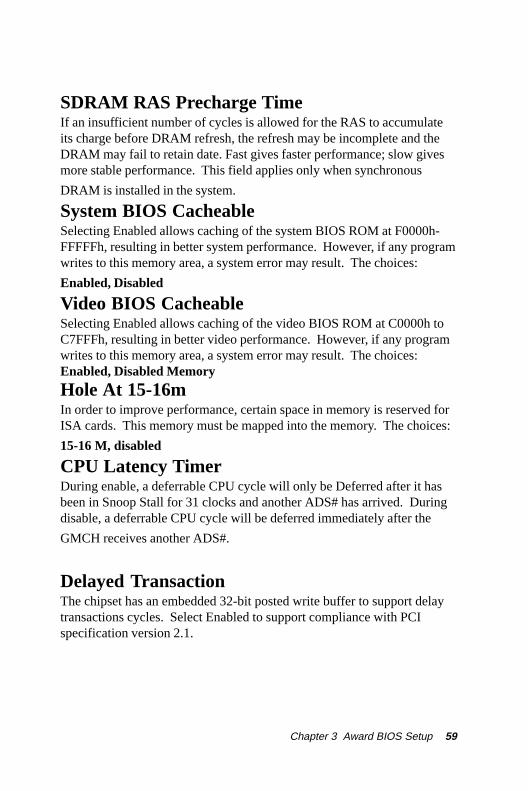
SDRAM RAS Precharge TimeIf an insufficient number of cycles is allowed for the RAS to accumulateits charge before DRAM refresh, the refresh may be incomplete and theDRAM may fail to retain date. Fast gives faster performance; slow givesmore stable performance. This field applies only when synchronous
DRAM is installed in the system.
System BIOS CacheableSelecting Enabled allows caching of the system BIOS ROM at F0000h-FFFFFh, resulting in better system performance. However, if any programwrites to this memory area, a system error may result. The choices:
Enabled, Disabled
Video BIOS CacheableSelecting Enabled allows caching of the video BIOS ROM at C0000h toC7FFFh, resulting in better video performance. However, if any programwrites to this memory area, a system error may result. The choices:Enabled, Disabled Memory
Hole At 15-16mIn order to improve performance, certain space in memory is reserved forISA cards. This memory must be mapped into the memory. The choices:
15-16 M, disabled
CPU Latency TimerDuring enable, a deferrable CPU cycle will only be Deferred after it hasbeen in Snoop Stall for 31 clocks and another ADS# has arrived. Duringdisable, a deferrable CPU cycle will be deferred immediately after the
GMCH receives another ADS#.
Delayed TransactionThe chipset has an embedded 32-bit posted write buffer to support delaytransactions cycles. Select Enabled to support compliance with PCIspecification version 2.1.

60 SBC-776 User Manual
AGP Graphics Aperture SizeSelect the size of Accelerated Graphics Port (AGP) aperture. Theaperture is a portion of the PCI memory address range dedicated forgraphics memory address space. Host cycles that hit the aperture rangeare forwarded to the AGP without any translation. The choices: 32M,64M.
Display Cache FrequencyDisplay cache frequency will allow for the level the of the share memoryprovided by the Intel 815E chipset to be adjusted.
The settings are 100MHz and 133 MHz.
System Memory FrequencySelect the onboard display cache frequency. The settings are auto,
100MHz and 133MHz.
On-Chip Video Window SizeSelect the on-chip video window size for VGA drive use.The choices: 32MB, 64MB, Disabled
Initial Display CacheCas# LatencySelect the local memory clock period. The number ofclock cycles of CAS# Latency depends on the OnboardDisplay Cache timing. The choice: 2,3Paging Mode ControlSelect the paging mode control. The choice: open,closeRAS-to-CAS OverrideThis item allows you to insert a timing delay between theCAS and RAS strobe signals, used when Onboarddisplay cache is written to, read from, or refreshed.During by CAS#LT, this will depend on the OnboardDisplay Cache CAS# Latency setting. During Override(2), RAS-to-CAS time = 2Ras# TimingThis item controls RAS# active to Precharge, and refreshto RAS# active delay ( in local memory clock ). Thechoices: Fast, SlowRas# Precharge TimingThis item controls RAS# precharge ( in loca memoryclocks). The choices: Fast, slow

Chapter 3 Award BIOS Setup 61
Integrated Peripherals
On-Chip Primary PCI IDEThe system chipset contains a PCI IDE interface with support fortwo IDE channels. Select Enabled to activate the primary and/orsecondary IDE interface. Select Disabled to deactivate thisinterface, if you install a primary and/or secondary add-in IDEinterface.On-Chip Secondary PCI IDEThe chipset contains a PCI IDE interface with support for two IDEchannels. Select Enabled to activate the secondary IDE interface.Select Disabled to deactivate this interface.The choices: Enable, Disable
IDE Primary/Secondary Master/Slave PIOThe four IDE PIO (Programmable Input/Output) fields let you set aPIO mode (0-1) for each of the four IDE devices that the onboardIDE interface supports. Modes 0 through 4 provide successivelyincreased performance. In Auto mode, the system automaticallydetermines the best mode for each device.The choices: Auto, Mode 0, Mode 1, Mode 2, Mode 3, Mode 4.
62 SBC-776 User Manual
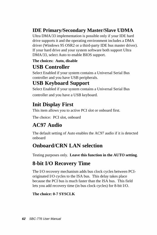
IDE Primary/Secondary Master/Slave UDMAUltra DMA/33 implementation is possible only if your IDE harddrive supports it and the operating environment includes a DMAdriver (Windows 95 OSR2 or a third-party IDE bus master driver).If your hard drive and your system software both support UltraDMA/33, select Auto to enable BIOS support.
The choices: Auto, disable
USB ControllerSelect Enabled if your system contains a Universal Serial Buscontroller and you have USB peripherals.
USB Keyboard SupportSelect Enabled if your system contains a Universal Serial Bus
controller and you have a USB keyboard.
Init Display FirstThis item allows you to active PCI slot or onboard first.
The choice: PCI slot, onboard
AC97 AudioThe default setting of Auto enables the AC97 audio if it is detectedonboard
Onboard/CRN LAN selection
Testing purposes only. Leave this function in the AUTO setting.
8-bit I/O Recovery TimeThe I/O recovery mechanism adds bus clock cycles between PCI-originated I/O cycles to the ISA bus. This delay takes placebecause the PCI bus is much faster than the ISA bus. This fieldlets you add recovery time (in bus clock cycles) for 8-bit I/O.
The choice: 0-7 SYSCLK

Chapter 3 Award BIOS Setup 63
16-bit I/O Recovery TimeThe I/O recovery mechanism adds bus clock cycles between PCI-originated I/O cycles to the ISA bus. This delay takes placebecause the PCI bus is much faster than the ISA bus. This fieldlets you add recovery time (in bus clock cycles) for 16-bit I/O.
The choice: 1 SYSCLK, 2SYSCLK, 3SYSCLK, 4 SYSCLK
IDE HDD Block ModeBlock mode is also called block transfer, multiple commands, ormultiple sector read/write. If your IDE hard drive supports blockmode (most new drives do), select Enabled for automatic detectionof the optimal number of block read/write per sector the drive cansupport.
Power on FunctionSelect the different manners for powering on the system.The choices: Keyboard 98, password, any key, hot key, button
only, mouse click, mouse move.
KB Power on PasswordThe system will ask for a password, after entering the correct
password the keyboard can then be used.
Ir Transmission DelayThe system IR component transmits and retrieves data from itsworking environment, if enabled the IR system will detect ortransmit information. If disabled the IR system will be unable to
operate.
Use IR PinsConsult your IR peripheral documentation to select the correctsetting of the TxD and RxD signals.

64 SBC-776 User Manual
Onboard FDC ControllerSelect Enabled if your system has a floppy disk controller (FDC)installed on the system board and you wish to use it. If you installan add-in FDC or the system has no floppy drive, select Disabledin this field.
UART Mode SelectSelect an operating mode for the second serial port:
Normal RS-232C serial port
IrDA 1.0 Infrared port compliant with IrDA 1.0
specification
IrDA SIR IrDA-compliant serial infrared port
IrDA MIR 1 MB/sec infrared port
IrDA FIR Fast infrared standard
ASK IR Amplitude shift keyed infrared port
SCR
Hot Key Power OnSimply pressing on the pre-selected keyboard key the system willpower on.
RxD, TxD ActiveConsult your IR peripheral documention to select the correct
setting of the TxD and RxD signals
UR2 Duplex ModeSelect the value required by the IR device connected to the IR prot.Full-duplex mode permits simultaneous two-direction transmission.Half-duplex mode permits transmission in one direction only at a
time. If no infrared port is present in the system, select disabled.
Use IR PinsConsult your IR peripheral documentation to select the correctsetting of the TxD and RxD signals.

Chapter 3 Award BIOS Setup 65
Onboard Serial Ports (1, 2)Normally, the main board’s I/O chips will occupy a certain portionof memory space. For each I/O device the computer provides anI/O address. The more devices attached the more address neededto organize the memory storage areas. If all the I/O devices wererun through the same address, your devices would come to a nearhalt. By providing the end user with four serial ports this allowsdevices to run more efficiently if needed. Also the correspondinginterrupt needs to be selected.
Selections of logical COM port addresses are as follows. ( 3F8/IRQ4, 3E8/IRQ4, 2F8/IRQ3, 2E8/IRQ3)
Onboard Parallel PortSelect a logical LPT port address and corresponding interrupt forthe physical parallel port
The Choice: 378/IRQ7, 278/IRQ5, 3BC/IRQ7, disabled
Parallel Port ModeTwo bidirectional parallel ports. Supports SPP, ECP, EPP,ECP + EPP.
EPP Mode SelectSelect the EPP port type 1.7 or 1.9
ECP Mode Use DMASelect a DMA channel for the port.
PWRON After PWR-FailThis option will determine how the system will power on after apower failure.
The choice: off, on , former status

66 SBC-776 User Manual
Watch Dog TimerYou can enable the system watchdog timer, a hardware timer thatgenerates either an NMI or a reset when the software that itmonitors does not respond as expected each time the watch dogpolls it ( select the time period in a separate field ) The choice:Disabled, 20 sec, 30 sec, 40 sec, 50 sec, 1 min, 2 min, 4 min.

Chapter 3 Award BIOS Setup 67
Power Management Setup
ACPI FunctionThis item allows you to enable/disable the Advanced Configuration
and Power Management (ACPI). The Choices: Enable/Disable
ACPI Suspend TypeThis item will set which ACPI suspend type will be used.
S1 (POS) The S1 sleeping state is low wake-up latency sleepingstate. In this state, no system context is lost (CPU or chip set) andhardware maintains all system context.
S3 (STR) The S3 state is a low wake-up latency sleeping statewhere all system context is lost expect system memory. CPU,cache and chipset context are lost in this state. Hardware maintainsmemory context and restores some CPU and L2 configurationcontext.

68 SBC-776 User Manual
Power ManagementThis category allows you to select the type ( or degree ) of powersaving and is directly related to the following modes:1. HDD Power Down2. Doze Mode3. Suspend Mode
)tluafeD(elbasiD .sedomruofllaelbasiD.tnemeganamrewopoN
gnivaSrewoP.niM1=edomezoD.nemeganamrewopmuminiM
=edomdnepsuS.ruoh1=edomybdnatS.ruoh.setunim51=nwoDrewoPDDH.ruoh1
gnivaSrewoP.xaM
--tnemeganamrewopmumixaM YLNO.S’UPCLSROFELBALIAVA =edomesoD
edomdnepsuS,.nim1=edomybdnatS,.nim1.nim1=nwoDrewoPDDHdna,.nim1=
denifeDresU
nehW.yllaudividniedomhcaetesotuoyswollA.nim1morferasegnatehtfohcae,delbasidton
hcihwnwoDrewoPDDHroftpecxeruoh1ot.elbasiddna.nim51ot.nim1morfsegnar
Video Off MethodThis determines the manner in which the monitor is blanked.
knalB+CNYSH/VffonrutotmetsysehtesuaclliwnoitcelessihTstropnoitazinorhcnyslatnozirohdnalacitreveht
reffuboedivehtotsknalbetirwdna
neercSknalB reffuboedivehtotsknalbsetirwylnonoitposihT
SMPD gnilangistnemeganamrewopyalpsidlaitinI
Chapter 3 Award BIOS Setup 69
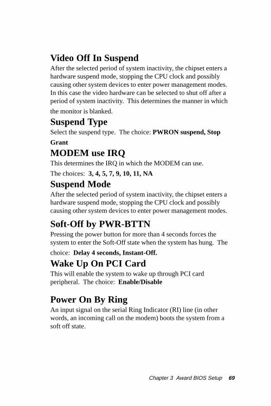
Video Off In SuspendAfter the selected period of system inactivity, the chipset enters ahardware suspend mode, stopping the CPU clock and possiblycausing other system devices to enter power management modes.In this case the video hardware can be selected to shut off after aperiod of system inactivity. This determines the manner in which
the monitor is blanked.
Suspend TypeSelect the suspend type. The choice: PWRON suspend, Stop
Grant
MODEM use IRQThis determines the IRQ in which the MODEM can use.
The choices: 3, 4, 5, 7, 9, 10, 11, NA
Suspend ModeAfter the selected period of system inactivity, the chipset enters ahardware suspend mode, stopping the CPU clock and possiblycausing other system devices to enter power management modes.
Soft-Off by PWR-BTTNPressing the power button for more than 4 seconds forces thesystem to enter the Soft-Off state when the system has hung. The
choice: Delay 4 seconds, Instant-Off.
Wake Up On PCI CardThis will enable the system to wake up through PCI cardperipheral. The choice: Enable/Disable
Power On By RingAn input signal on the serial Ring Indicator (RI) line (in otherwords, an incoming call on the modem) boots the system from asoft off state.

70 SBC-776 User Manual
USB KB Wake-up From S3This option is used to Enabled/Disabled USB keyboard wake up
with suspend to RAM. The Choice: Enabled/Disabled
Power On after Power FailAfter initial power failure, the system will attempt to power upagain in the setting that the end user has selected.
The Choice: ON/OFF/Former status
CPU Thermal-ThrottlingSelect the CPU Thermal-Throttling rate for your system.The choice: 12.5%, 25%, 37.5%, 50%, 62.5% 75%, 87.5%
Resume By AlarmThis option is used to Enable/Disable USB keyboard wake up withsuspend to RAM.The choices: Enable, disable
Date AlarmYou can choose which month the system will boot up. Set to 0 toboot everyday.Time AlarmYou can choose what hour, minute and second the system will bootup.

Chapter 3 Award BIOS Setup 71
<Reload Global Timer Events> PM events are I/O events whose occurrence can prevent
the system from entering a power saving mode or canawaken the system from such a mode. In effect, thesystem remains alert for anything which occurs to a devicewhich is configured as Enabled, even when the system isin a power down mode.
Primary IDE 0Primary IDE 1Secondary IDE 0Secondary IDE 1FDD, COM, LPT PortPCI PIRQ (A-D)#
72 SBC-776 User Manual
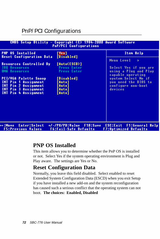
PnP/PCI Configurations
Reset Configuration DataNormally, you leave this field disabled. Select enabled to resetExtended System Configuration Data (ESCD) when you exit Setupif you have installed a new add-on and the system reconfigurationhas caused such a serious conflict that the operating system can notboot. The choices: Enabled, Disabled
PNP OS InstalledThis item allows you to determine whether the PnP OS is installedor not. Select Yes if the system operating environment is Plug andPlay aware. The settings are Yes or No.

Chapter 3 Award BIOS Setup 73
Resources Controlled ByThe Award Plug and Play BIOS has the capacity to automaticallyconfigure all of the boot and Plug and Play compatible devices.However, this capability means absolutely nothing unless you areusing a Plug and Play operating system such as Windows ® 95. Ifyou set this field to “manual” choose specific resources by goinginto each of the sub menu that follows this field ( a sub menu isproceeded by a “>”. The choices: Auto, Manual.
PCI/VGA Palette SnoopLeave this field at Disabled. Choices: Enabled, Disabled.

74 SBC-776 User Manual
PC Health Status
CPU Warning TemperatureDuring enabled, this will warn the user when the CPU temperaturereach a certain temperature.
Options: Disabled, 75°C/167°F, 70°C/158°F, 65°C/149°F, 60°C/140°F
Shutdown TemperatureYour system can be configured to shutdown once reaching a certaintemperature. To protect your system from overheating or damage,select a certain temperature level in the PC Health Status menu.
Options: Disabled, 75°C/167°F, 70°C/158°F, 65°C/149°F, 60°C/140°F

Chapter 3 Award BIOS Setup 75
Frequency/Voltage Control
Auto Detect DIMM/PCI CLKThis item allows you to enable/disable auto detect DIMM/PCI
clock. The choices: Enable/Disable
Spread SpectrumThis allows you to enable/disable the spread spectrum modulate.When the system clock generator pulses, the extreme values of thepulse generate excess EMI. Enabling pulse spectrum spreadmodulation changes the extreme pulse spikes to flat curves thusreducing EMI.
The choices: Enable, Disable
Clock By Slight AdjustThis item allows you to select the CPU clock from 166 MHz to100 MHz or 99 MHz to 66 MHz depending on the CPU host
clock.
CPU Clock RatioThis item allows you to select the CPU ratio. When using an IntelCPU this item will be hidden.
76 SBC-776 User Manual
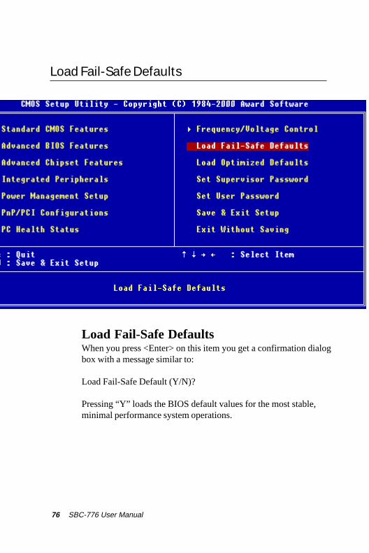
Load Fail-Safe Defaults
Load Fail-Safe DefaultsWhen you press <Enter> on this item you get a confirmation dialogbox with a message similar to:
Load Fail-Safe Default (Y/N)?
Pressing “Y” loads the BIOS default values for the most stable,minimal performance system operations.

Chapter 3 Award BIOS Setup 77
Load Optimized Default
Load Optimized DefaultWhen you press <Enter> on this item you get a confirmation dialogbox with a message similar to:
Load Optimized Defaults (Y/N)?
Pressing “Y” loads the default values that are factory settings foroptimal performance system operations

78 SBC-776 User Manual
Set Supervisor Password
When you select this function, a message appears at the center ofthe screen:
ENTER PASSWORD:
Type the password, up to eight characters, and press Enter. Typinga password clears any previously entered password from CMOSmemory.
Now the message changes:
CONFIRM PASSWORD:
Again, type the password and press Enter.
To abort the process at any time, press Esc.
In the Security Option item in the BIOS Features Setup screen,select System or Setup:
System Enter a password each time the system boots and when ever you enter Setup.
Setup Enter a password when ever you enter Setup.
NOTE: To clear the password, simply press Enter when asked toenter a password. Then the password function is disabled.

Chapter 3 Award BIOS Setup 79
Set User Password
When you select this function, a message appears at the center ofthe screen:
ENTER PASSWORD:
Type the password, up to eight characters, and press Enter. Typinga password clears any previously entered password from CMOSmemory.
Now the message changes:
CONFIRM PASSWORD:
Again, type the password and press Enter.
To abort the process at any time, press Esc.
In the Security Option item in the BIOS Features Setup screen,select System or Setup:
System Enter a password each time the system boots and when ever you enter Setup.
Setup Enter a password when ever you enter Setup.
NOTE: To clear the password, simply press Enter when asked toenter a password. Then the password function is disabled.

80 SBC-776 User Manual
Save to CMOS and EXIT
Save to CMOS and EXITPressing <Enter> on this item asks for confirmation:
Save to CMOS and Exit (Y/N)?
Pressing “Y” stores the selections made in the menus in CMOS, aspecial section of memory that stays on after you turn your systemoff. The next time you boot your computer, the BIOS configuresyour system according to the Setup selections stored in CMOS.After saving the values the system is restarted again.

Chapter 3 Award BIOS Setup 81
Quit without Saving
Exit Without SavingPressing <Enter> on this item asks for confirmation:
Quit Without Saving (Y/N)?
This allows you to exit Setup without storing in CMOS any change.The previous selections remain in effect. This exits the Setuputility and restarts your computer.