GigE für e- ketten GigE for e-chains Kohle und Staub Coal and dust.
Upload
emi-eguchiCategory
view
233download
7description

Camera and Driver Features
V1.0.0
04 July 2013
Allied Vision Technologies GmbHTaschenweg 2aD-07646 Stadtroda / Germany
AVT GigE Cameras

AVT GigE Camera and Drivers Features V1.0.0
2
Legal notice
TrademarksUnless stated otherwise, all trademarks appearing in this document of Allied Vision Technologies are brands protected by law.
WarrantyThe information provided by Allied Vision Technologies is supplied without any guarantees or warranty whatsoever, be it specific or implicit. Also, excluded are all implicit warranties concerning the negotiability, the suitability for specific applications or the non-breaking of laws and patents. Even if we assume that the information supplied to us is accurate, errors and inaccuracy may still occur.
CopyrightAll texts, pictures and graphics are protected by copyright and other laws pro-tecting intellectual property. It is not permitted to copy or modify them for trade use or transfer, nor may they be used on websites.
Allied Vision Technologies GmbH 07/2013All rights reserved.Managing Director: Mr. Frank GrubeTax ID: DE 184383113
Headquarters:
Taschenweg 2aD-07646 Stadtroda, GermanyTel: +49 (0)36428 6770Fax: +49 (0)36428 677-28e-mail: [email protected]

Contents
Contacting Allied Vision Technologies ................................................... 6
Introduction ............................................................................................................ 7
Document history............................................................................................................ 7Conventions used in this manual ........................................................................................ 8Additional information..................................................................................................... 8
AVT GigE GenICam features ........................................................................10
Camera controls..................................................................................................11Acquisition ............................................................................................................ 11
AcquisitionAbort [Command] ...................................................................................... 11AcquisitionFrameCount [Integer] R/W........................................................................... 11AquisitionFrameRateAbs [Float] R/W ............................................................................ 11AquisitionFrameRateLimit [Float] R .............................................................................. 11AcquisitionMode [Enum] R/W...................................................................................... 11AcquisitionStart [Command] ....................................................................................... 12AcquisitionStop [Command] ....................................................................................... 12RecorderPreEventCount [Integer] R/W .......................................................................... 12Trigger.................................................................................................................... 13
Controls ................................................................................................................. 14BlackLevelControl..................................................................................................... 14CCDTemperatureOK [Integer] R .................................................................................... 15ColorTransformationControl........................................................................................ 15DSPSubregion .......................................................................................................... 16EdgeFilter [Enum] R/W............................................................................................... 16DefectMask.............................................................................................................. 17Exposure................................................................................................................. 17GainControl/Gain...................................................................................................... 20Gamma [Float] R/W ................................................................................................... 21Hue [Float] R/W ....................................................................................................... 22IODMode [Enum] R/W ................................................................................................ 22Iris......................................................................................................................... 22LensDrive ................................................................................................................ 25LUTControl .............................................................................................................. 25NirMode [Enum] R/W ................................................................................................. 27Saturation [Float] R/W............................................................................................... 28SubstrateVoltage ...................................................................................................... 28Whitebalance ........................................................................................................... 28
DeviceStatus ........................................................................................................ 29DeviceTemperature [Float] R ...................................................................................... 29DeviceTemperatureSelector [Enum] R/W ....................................................................... 29
EventControl ........................................................................................................ 30EventData ............................................................................................................... 30
AVT GigE Camera and Drivers Features V1.0.0
3
EventID................................................................................................................... 30EventNotification [Enum] R/W..................................................................................... 31EventSelector [Enum] R/W.......................................................................................... 31EventsEnable1 [Integer] R/W ...................................................................................... 31
GigE ........................................................................................................................ 32BandwidthControlMode [Enum] R/W............................................................................. 32ChunkModeActive [Boolean] R/W ................................................................................ 32NonImagePayloadSize [Integer] R ............................................................................... 32PayloadSize [Integer] R ............................................................................................. 32StreamBytesPerSecond [Integer] R/W........................................................................... 33StreamFrameRateConstrain [Boolean] R/W .................................................................... 33StreamHold ............................................................................................................. 33Timestamp............................................................................................................... 34
IO ............................................................................................................................. 35StatusLED................................................................................................................ 35Strobe .................................................................................................................... 36SyncIn .................................................................................................................... 37SyncOut .................................................................................................................. 37
ImageFormat ........................................................................................................ 38Height [Integer] R/W................................................................................................. 38HeightMax [Integer] R ............................................................................................... 38ImageSize [Integer] R................................................................................................ 38OffsetX [Integer] R/W ................................................................................................ 39OffsetY [Integer] R/W ................................................................................................ 39PixelFormat [Enum] R/W ............................................................................................ 39Width [Integer] R/W.................................................................................................. 40WidthMax [Integer] R ................................................................................................ 40
ImageMode ........................................................................................................... 40BinningHorizontal [Integer] R/W................................................................................. 40BinningVertical [Integer] R/W..................................................................................... 41DecimationHorizontal [Integer] R/W ............................................................................ 41DecimationVertical [Integer] R/W ................................................................................ 41SensorHeight [Integer] R/C ........................................................................................ 41SensorWidth [Integer] R/C.......................................................................................... 41
Info .......................................................................................................................... 42DeviceFirmwareVersion [String] R/C ............................................................................. 42DeviceID [String] R/C ................................................................................................ 42DeviceUserID [String] R/W.......................................................................................... 42DeviceModelName [String] R/W ................................................................................... 42DevicePartNumber [String] R/C ................................................................................... 42DeviceScanType [Enum] R/C........................................................................................ 42DeviceVendorName [String] R/C .................................................................................. 42FirmwareVerBuild [Integer] R/C................................................................................... 42FirmwareVerMajor [Integer] R/C .................................................................................. 42FirmwareVerMinor [Integer] R/C .................................................................................. 42SensorBits [Integer] R/C ............................................................................................ 42SensorType [Enum] R/C.............................................................................................. 42
SavedUserSets..................................................................................................... 42UserSetDefaultSelector [Enum] R/W ............................................................................. 43
AVT GigE Camera and Drivers Features V1.0.0
4
UserSetLoad [Command] ............................................................................................ 43UserSetSave [Command] ............................................................................................ 43UserSetSelector [Enum] R/W....................................................................................... 43
Driver controls .....................................................................................................44GigE ........................................................................................................................ 44
Configuration........................................................................................................... 44Current ................................................................................................................... 44GevDeviceMACAddress [Integer] R................................................................................ 44GVCP ...................................................................................................................... 44GevSCPSPacketSize [Integer] R/W ................................................................................ 45Ptp......................................................................................................................... 45Persistent................................................................................................................ 46
Stream.................................................................................................................... 47Info ....................................................................................................................... 47Multicast................................................................................................................. 47Settings .................................................................................................................. 47Statistics................................................................................................................. 49
Index...........................................................................................................................51
AVT GigE Camera and Drivers Features V1.0.0
5
Contacting Allied Vision Technologies
AVT GigE Camera and Drivers Features V1.0.0
6
Contacting Allied Vision Technologies
Info
• Technical information:
http://www.alliedvisiontec.com
• Support:[email protected]
Allied Vision Technologies GmbH (Headquarters)Taschenweg 2a07646 Stadtroda, GermanyTel: +49 36428-677-0Fax: +49 36428-677-28e-mail: [email protected]
Allied Vision Technologies Canada Inc.101-3750 North Fraser WayBurnaby, BC, V5J 5E9, CanadaTel: +1 604-875-8855Fax: +1 604-875-8856e-mail: [email protected]
Allied Vision Technologies Inc.38 Washington StreetNewburyport, MA 01950, USAToll Free number +1 877-USA-1394Tel: +1 978-225-2030Fax: +1 978-225-2029e-mail: [email protected]
Allied Vision Technologies Asia Pte. Ltd.82 Playfair Road#07-02 D’Lithium, Singapore 368001Tel: +65 6634-9027Fax: +65 6634-9029e-mail: [email protected]
Allied Vision Technologies (Shanghai) Co. Ltd.2-2109 Hongwell International Plaza 1602# ZhongShanXi Road, Shanghai 200235, China Tel: +86 21-64861133Fax: +86 21-54233670e-mail: [email protected]
Introduction
Introduction
The document describes the standard and advanced camera controls for AVT GigE cameras as seen from the AVT Vimba Viewer, using the GenICam standard feature naming convention.
AVT offers following GigE Vision camera families: – Bigeye G– Mako G– Manta– Prosilica GB– Prosilica GC– Prosilica GE– Prosilica GS– Prosilica GT– Prosilica GX
This document can be applied to all of these families.
Document history
www
Follow this link to learn about GigE Vision cameras from AVT.
http://www.alliedvisiontec.com/emea/products/cameras/gigabit-ethernet/
Version Date Remarks
V1.0.0 2013-Jul-04 NEW MANUAL - RELEASE status
Table 1: Document history
AVT GigE Camera and Drivers Features V1.0.0
7
Introduction
Conventions used in this manual
To give this manual an easily understood layout and to emphasize important information, the following typographical styles and symbols are used:
Styles
Symbols
Additional information
AVT softwareAll software packages provided by AVT are free of charge and contain the fol-lowing components:• Drivers• Software Development Kit (SDK) for camera control and image acquisition• Examples based on the provided APIs of the SDK• Documentation and release notes• Viewer application to operate/configure the cameras
Style Function Example
Bold Highlighting important information control
Courier Camera feature Input
Courier Italics Possible feature values Mode
Parentheses and/or blue Links (Link)
Table 2: Styles
Note
This symbol highlights important information.
www
This symbol highlights URLs for further information. The URL itself is shown in blue.
Example:
http://www.alliedvisiontec.com
AVT GigE Camera and Drivers Features V1.0.0
8

Introduction
Third-party softwareIn addition to the software provided by AVT, there are numerous GigE Vision Standard compliant third-party software options available. In general, third-party software provides increased functionality such as image processing and video recording.
www
All software packages (including documentation and release notes) provided by AVT can be downloaded at:
http://www.alliedvisiontec.com/emea/support/downloads/software.html
www
For a list of compliant third-party software see:
http://www.alliedvisiontec.com/emea/products/software/third-party-software.html
AVT GigE Camera and Drivers Features V1.0.0
9
AVT GigE GenICam features
AVT GigE GenICam features
Note
This is the master document for all AVT GigE camera models. Some features are not available for all camera models.
Example:
• White balance is not available for monochrome cameras.
Some features are implemented in the cameras, but are not always available.
Examples:
• Color correction features are implemented in Manta, Mako G, and GT color cameras, but not the GB, GE, GC, GX cam-eras.
• Color Correction is supported in Manta, Mako G and GT; but it is not available in color cameras if they are oper-ated with Bayer pixel formats, but works if debayering is done within the camera.
Note
For AVT Vimba Viewer users: camera feature type is given in []:
• Enum• Float• Integer• String• Command• Boolean
Note
The following abbreviations are used:
R/W = feature is read/write
R/C = feature is read only and constant
R = feature is read only and may change
AVT GigE Camera and Drivers Features V1.0.0
10
Camera controls
Camera controls
AcquisitionThis group of controls relates to image acquisition.
AcquisitionAbort [Command]Software command to stop camera from receiving frame triggers and abort the current acquisition. A partially transferred image will be completed.
AcquisitionFrameCount [Integer] R/W
Defines the number of frames to capture in a limited sequence of images. Used with AcquisitionMode = MultiFrame and Recorder. In Recorder mode, AcquisitionFrameCount cannot exceed StreamHoldCapac-ity.
AquisitionFrameRateAbs [Float] R/W
When either the FrameStart trigger mode is disabled, or TriggerSe-lector = FrameStart and TriggerSource = FixedRate, this con-trol specifies the frame rate. Depending on the exposure duration, the camera may not achieve the frame rate set here.
AquisitionFrameRateLimit [Float] R
The maximum frame rate possible for the current exposure duration and image format.
AcquisitionMode [Enum] R/WDetermines the behavior of the camera when acquisition start is triggered.
Range:[1 – 65535] Default: 1 Units: Frames
Range: [Camera dependent] Units: Frames per second
Range: [Camera dependent] Units: Frames per second
Continuous [Default] After an acquisition start event, the camera will continuously receive frame trigger events.See TriggerSelector and TriggerSource for more information.
SingleFrame The camera will only deliver a single frame trigger event. Further trigger events will be ignored until acquisition is stopped and restarted
AVT GigE Camera and Drivers Features V1.0.0
11
Camera controls
AcquisitionStart [Command]Software command to start camera receiving frame triggers. Valid when Trig-gerMode = Off. See TriggerSelector = FrameStart trigger.
AcquisitionStop [Command]Software command to stop camera from receiving frame triggers. Valid when TriggerMode = Off. See TriggerSelector = FrameStart trigger.
RecorderPreEventCount [Integer] R/W
Valid when AcquisitionMode = Recorder. The number of frames returned before the AcquisitionRecord trigger event, with Aquisi-tionFrameCount minus RecorderPreEventCount frames being returned after the AcquisitionRecord trigger event.
MultiFrame The camera will acquire the number of images specified by AcquisitionFrameCount. Further trigger events will be ignored until acquisition is stopped and restarted
Recorder The camera will continuously record images into the cam-era on-board memory, but will not send them to the host until an AcquisitionRecord trigger signal is received. Further AcquisitionRecord trigger events will be ignored until acquisition is stopped and restarted.
Combined with the RecorderPreEventCount con-trol, this feature is useful for returning any number of frames before a trigger event.
When AcquisitionRecord trigger is received, the currently imaging/acquiring image will complete as nor-mal, and then at least one more image will be taken. The memory is a circular buffer, that starts rewriting images once it is full. Its size is determined by Acquisition-FrameCount
Range:[0 – 65535] Default: 0 Units: Frames
Note
At least one image must be captured after the AcquisitionRecord trigger event, i.e., you cannot set RecorderPreEventCount = 1, and AcquisitionFrameCount = 1.
AVT GigE Camera and Drivers Features V1.0.0
12
Camera controls
TriggerThis group of controls relates to how an image frame is initiated or triggered.
TriggerActivation [Enum] R/W
Type of activation, for hardware triggers. This controls edge/level and polarity sensitivities.
TriggerDelayAbs [Float] R/W
Start-of-image can be delayed to begin some time after a trigger event is received by the camera. This feature is valid only when TriggerSource is set to external trigger (i.e. Line1, Line2). This control is a common trigger to sync with a strobe lighting source, which will inherently have some fixed setup time.
TriggerMode [Enum] R/W
Enables or disables trigger set in TriggerSelector.
TriggerOverlap [Enum] R/WPermitted window of trigger activation, relative to previous frame. Does not work with Software triggering. Only external.
RisingEdge [Default] Rising edge triggerFallingEdge Falling edge triggerAnyEdge Rising or falling edgeLevelHigh Active high signalLevelLow Active low signal
Range:[0 – Camera dependent] Default: 0 Units: μs
Off Trigger disabledOn [Default] Trigger enabled
Note
If TriggerMode = Off and TriggerSelector = FrameStart, images triggered in FixedRate at AcquisitionFrameRateAbs.
Off [Default] Any external trigger received before a high FrameTriggerReady signal is ignored
PreviousFrame Any external trigger received before FrameTrigger-Ready is latched and used to trigger the next frame
AVT GigE Camera and Drivers Features V1.0.0
13
Camera controls
TriggerSelector [Enum] R/WSelects a trigger, then use the controls {TriggerMode, TriggerSoft-ware, TriggerSource, TriggerActivation, TriggerOverlap, TriggerDelayAbs} to setup and read the trigger features.
TriggerSoftware [Command]Triggers an image. Valid when TriggerSource = Software.
TriggerSource [Enum] R/WDetermines how an image frame is initiated within an acquisition stream.
ControlsBlackLevelControl
BlackLevel [Float] R/W
Black level value. Setting the Gain does not change the BlackLevel.
BlackLevelSelector [Enum] R/W
Selects which black level is controlled by the various black level features.
FrameStart [Default] The trigger which starts each image (when acquisition is running)
AcquisitionStart The trigger which starts the acquisition processAcquisitionEnd The trigger which ends the acquisition processAcquisitionRecord The trigger which initiates the sending of recorded
images from the camera on-board memory to the host
Note
An acquisition stream must be started in order to trigger/receive individual frames. For Freerun and FixedRate the first frame is synchronized to AcquisitionStart trigger.
Freerun [Default] Camera runs at maximum supported frame rate depending on the exposure time and region of interest size
Line1 External trigger Line1Line2 External trigger Line2Line3 External trigger Line3Line4 External trigger Line4FixedRate Camera self-triggers at a fixed frame rate defined by
AcquisitionFrameRateAbsSoftware Software initiated image capture
Range: [0 – 255.75] Default: 0
Possible values: All
AVT GigE Camera and Drivers Features V1.0.0
14
Camera controls
CCDTemperatureOK [Integer] RCurrent temperature status of the CCD sensor. Momentary temperature status ofthe CCD sensor. Indicates if CCD sensor has desired cooling temperature.
ColorTransformationControlThis section describes features related to color transformations in the AVT GigE color cameras.
Definition The color transformation is a linear operation taking as input the triplet Rin, Gin, Bin for an RGB color pixel. This triplet is multiplied by a 3x3 matrix.This color transformation allows to change the coefficients of the 3x3 matrix.
ColorTransformationMode [Enum] R/WSelects the mode for the color transformation.
ColorTransformationSelector [Enum] R/W
Selects which color transformation module is controlled by the various color transformation features.
ColorTransformationValue [Float] R/W
Represents the value of the selected gain factor or offset inside the transforma-tion matrix.
ColorTransformationValueSelector [Enum] R/WSelects the gain factor or offset of the transformation matrix if ColorTrans-formationMode = Manual
0 [Default] The CCD sensor may be too hot. Acquired image data may have higher noise than expected or contain erroneous pixels at long exposure times
1 The CCD sensor temperature is in the desired temperature range. Acquired image data are OK
Off [Default] No color transformationManual Manually set ColorTransformationValue matrix
coefficientsTemp6500K Colors optimized for a surrounding color temperature 6500 K
Possible values: RGBtoRGB
Range: [-2 – 2] Default: 1
Gain00 [Default] Red contribution to the red pixel (multiplicative factor)Gain01 Green contribution to the red pixel (multiplicative factor)Gain02 Blue contribution to the red pixel (multiplicative factor)
RoutGoutBout
Gain00 Gain01 Gain02Gain10 Gain11 Gain12Gain20 Gain21 Gain22
x
RinGinBin
=
AVT GigE Camera and Drivers Features V1.0.0
15
Camera controls
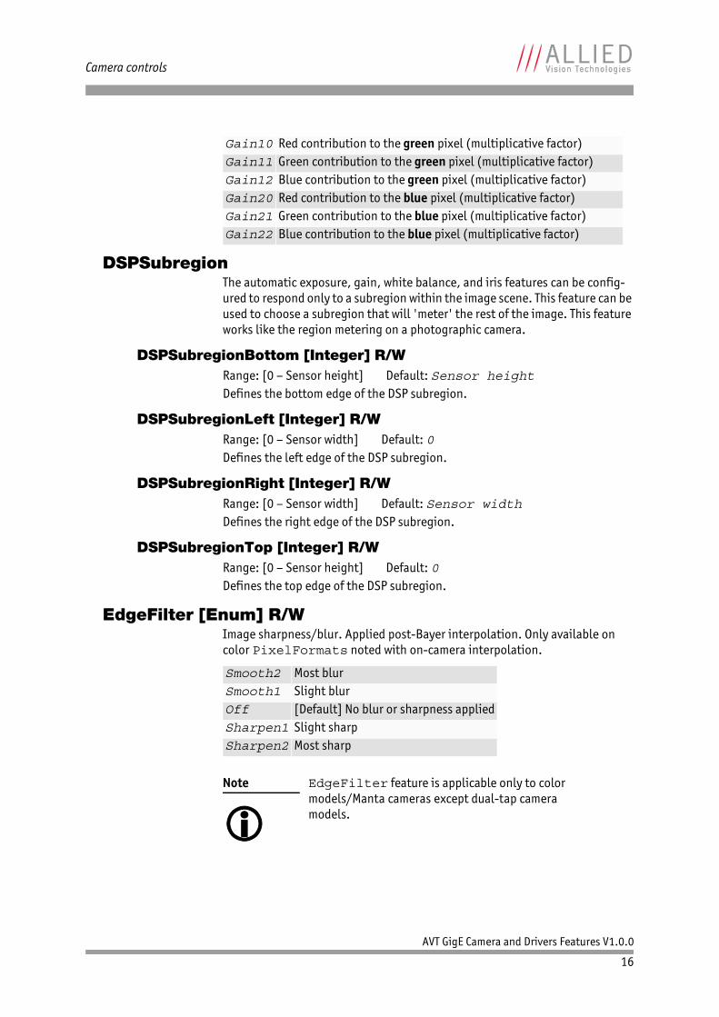
DSPSubregionThe automatic exposure, gain, white balance, and iris features can be config-ured to respond only to a subregion within the image scene. This feature can be used to choose a subregion that will 'meter' the rest of the image. This feature works like the region metering on a photographic camera.
DSPSubregionBottom [Integer] R/W
Defines the bottom edge of the DSP subregion.
DSPSubregionLeft [Integer] R/W
Defines the left edge of the DSP subregion.
DSPSubregionRight [Integer] R/W
Defines the right edge of the DSP subregion.
DSPSubregionTop [Integer] R/W
Defines the top edge of the DSP subregion.
EdgeFilter [Enum] R/WImage sharpness/blur. Applied post-Bayer interpolation. Only available on color PixelFormats noted with on-camera interpolation.
Gain10 Red contribution to the green pixel (multiplicative factor)Gain11 Green contribution to the green pixel (multiplicative factor)Gain12 Blue contribution to the green pixel (multiplicative factor)Gain20 Red contribution to the blue pixel (multiplicative factor)Gain21 Green contribution to the blue pixel (multiplicative factor)Gain22 Blue contribution to the blue pixel (multiplicative factor)
Range: [0 – Sensor height] Default: Sensor height
Range: [0 – Sensor width] Default: 0
Range: [0 – Sensor width] Default: Sensor width
Range: [0 – Sensor height] Default: 0
Smooth2 Most blurSmooth1 Slight blurOff [Default] No blur or sharpness appliedSharpen1 Slight sharpSharpen2 Most sharp
Note
EdgeFilter feature is applicable only to color models/Manta cameras except dual-tap camera models.
AVT GigE Camera and Drivers Features V1.0.0
16

Camera controls
DefectMaskSome larger format sensors may contain defective columns. Class 1 and Class 0 sensors are available with no defective columns.
DefectMaskColumnEnable [Enum] R/WDefect masking replaces defective columns with interpolated values based on neighboring columns. Defective columns are detected and recorded at the fac-tory.
DefectMaskPixelEnable [Enum] R/WDefect masking replaces defective pixels with interpolated values based on neighboring pixels. Defective pixels are detected and recorded at the factory.
Exposure
ExposureAuto [Enum] R/WAuto algorithms use information from the camera’s current image and apply the following settings to the next image. Large changes in scene lighting may require several frames for the algorithm to stabilize.
If using ExposureAuto = Continuous, and GainAuto = Continuous simultaneously, priority is given to changes in exposure until ExposureAu-toMax is reached, at which point priority is given to changes in gain. Adding simultaneous IrisMode = Video/DCIris/PIrisAuto results in unde-fined, “race to target” behavior.
www
See the AVT modular concept document, or contact your AVT sales representative for more information:
http://www.alliedvisiontec.com/us/support/downloads/product-literature/avt-modular-concept.html
Enabled [Default] Enables masking of defective columnsDisabled Disables masking of defective columns
Enabled [Default] Enables masking of defective pixelsDisabled Disables masking of defective pixels
Off [Default] The automatic mode is OffOnce Auto-exposure occurs until target is achieved, then
ExposureAuto returns to OffContinuous The exposure time will vary continuously according to the
scene illumination. The auto exposure function operates according to the ExposureAuto and DSPSubregion controls
other The exposure time will be controlled by an external signal appearing on Line1 or Line2. In order for this feature to work, TriggerSelector = FrameStart and TriggerSource must be set to Line1 or Line2
AVT GigE Camera and Drivers Features V1.0.0
17
Camera controls
You can configure the auto exposure feature to respond only to a subregion within the image scene. This subregion can be configured with the DSPSub-region feature.
ExposureAutoControl
ExposureAutoAdjustTol [Integer] R/W
Tolerance in variation from ExposureAutoTarget in which the auto expo-sure algorithm will not respond. It can be used to limit exposure setting changes to only larger variations in scene lighting.
ExposureAutoAlg [Enum] R/WThe following algorithms can be used to calculate auto exposure:
ExposureAutoMax [Integer] R/W
The upper bound to the exposure setting in auto exposure mode. This is useful in situations where frame rate is important. This value would normally be set to something less than (as a rough estimate)1x10⁶/(desired frame rate).
ExposureAutoMin [Integer] R/W
The lower bound to the exposure setting in auto exposure mode.
ExposureAutoOutliers [Integer] R/W
The total pixels from top of the distribution that are ignored by the auto expo-sure algorithm.
ExposureAutoRate [Integer] R/W
The rate at which the auto exposure function changes the exposure set-ting.100% is auto exposure adjustments running at full speed, and 50% is half speed.
Note
The camera must be acquiring images in order for the auto algorithm to update.
Range: [0-50] Default: 5 Unit: Percent
Mean [Default] The arithmetic mean of the histogram of the cur-rent image is compared to ExposureAutoTarget, and the next image adjusted in exposure time to meet this target. Bright areas are allowed to saturate
FitRange The histogram of the current image is measured, and the exposure time of the next image is adjusted so bright areas are not saturated
Range: [Camera dependent] Default: 500000 Units: μs
Range: [Camera dependent] Default: Camera dependent Units: μs
Range: [0– 1000] Default: 0 Units: 0.01% i.e. 1000 = 10%
Range: [1 – 100] Default: 100 Units: Percent
AVT GigE Camera and Drivers Features V1.0.0
18
Camera controls
ExposureAutoTarget [Integer] R/W
The general lightness or darkness of the auto exposure feature; specifically the target mean histogram level of the image—0 being black, 100 being white.
ExposureMode [Enum] R/W
Control for exposure duration.
ExposureTimeAbs [Float] R/W
The sensor integration time.
Shutter [Enum] R/WActivate or deactivate the mechanical shutter of Bigeye G-629B Cool cameras.
Range: [0 – 100] Default: 50 Units: Percent
Timed [Default] The camera exposure time is set by ExposureTimeAbs
Range: [Camera dependent] Units: μs
Off Deactivate the mechanical shutter. Use this mode, if you operate the camera with pulsed light sources
On [Default] Activate the mechanical shutter. If activated, the mechanical shutter opens upon each exposure cycle and closes again, when the exposure is over. Use this mode, if you operate the camera with constant light sources, due to the full frame sensor
SyncIn1 Enables or disables the mechanical shutter dependent on the level of LineIn1
SyncIn2 Enables or disables the mechanical shutter dependent on the level of LineIn2
SyncIn3 Enables or disables the mechanical shutter dependent on the level of LineIn3
SyncIn4 Enables or disables the mechanical shutter dependent on the level of LineIn4
SyncIn5 Enables or disables the mechanical shutter dependent on the level of LineIn5
Note
The shutter feature is intended to control the exposure by means of a mechanical shutter. It should not be confused with any other exposure control feature.
The mechanical shutter is available ONLY on the Bigeye G-629B Cool camera.
AVT GigE Camera and Drivers Features V1.0.0
19
Camera controls
GainControl/GainThis feature controls the gain settings applied to the sensor.
Gain [Float] R/W
The gain setting applied to the sensor. For best image quality, the gain setting should be set to zero. However, in low-light situations, it may be necessary to increase the gain setting.
GainAuto [Enum] R/WAuto algorithms use information from the camera’s current image and apply the following settings to the next image. Large changes in scene lighting may require 2-3 frames for the algorithm to stabilize.
If using ExposureAuto = Continuous, and GainAuto = Continuous simultaneously, priority is given to changes in exposure until ExposureAu-toMax is reached, at which point priority is given to changes in gain. Adding simultaneous IrisMode = Video/DCIris/PIrisAuto results in unde-fined, “race to target” behavior.
You can configure the auto gain feature to respond only to a subregion within the image scene. This subregion can be configured with the DSPSubregion feature.
GainAutoControl
GainAutoAdjustTol [Integer] R/W
Tolerance in variation from GainAutoTarget in which the auto exposure algorithm will not respond. This feature is used to limit auto gain changes to only larger variations in scene lighting.
Range: [Camera dependent] Default: 0 Units: dB
Off [Default] The automatic mode is OffOnce Auto-gain occurs until target is achieved, then GainAuto
returns to OffContinuous The gain will vary continuously according to the scene illu-
mination. The auto exposure function operates according to the ExposureAutoControl and DSPSubregion controls
Note
The camera must be acquiring images in order for the auto algorithm to update.
Range: [0 – 50] Default: 5 Units: Percent
GdB 20VoutVin
-----------
log=
AVT GigE Camera and Drivers Features V1.0.0
20
Camera controls
GainAutoMax [Float] R/W
The upper bound to the gain setting in auto gain mode.
GainAutoMin [Float] R/W
The lower bound to the gain setting in auto gain mode.
GainAutoOutliers [Integer] R/W
The total pixels from top of the distribution that are ignored by the auto gain algorithm.
GainAutoRate [Integer] R/W
The rate at which the auto gain function changes. A percentage of the maximum rate.
GainAutoTarget [Integer] R/W
The general lightness or darkness of the auto gain feature. A percentage of max-imum brightness.
GainRaw [Integer] R/W
Gain value of analog A/D stage.
GainSelector [Enum] R/W
Control for gain selection.
Gamma [Float] R/W
Nonlinear brightness control. Applies gamma value to the raw sensor signal (via LUT).
For Manta type A If Gamma is ON, LUT 1 is used to do the gamma transform. The original LUT val-ues will be stored temporarily. If Gamma is ON, and you read out LUT1: you only get stored LUT values but not Gamma values. In general, Gamma values can‘t be read out. If Gamma is OFF, LUT position 1 contains optional user defined LUT values.
Range: [0 – Camera dependent] Units: dB
Range: [0 – Camera dependent] Default: 0 Units: dB
Range: [1 – 1000] Default: 0 Units: 0.01%, i.e. 1000 = 10%
Range: [0 – 100] Default: 100 Units: Percent
Range: [0 – 100] Default: 50 Units: Percent
Range: [Camera dependent] Default: 0 Units: dB
Possible value: All
Range: Camera dependent Default: 1.00 Units: Output = (Input)Gamma
1.00 Gamma OFF (no Gamma correction)
Values other than 1.00 Gamma ON
AVT GigE Camera and Drivers Features V1.0.0
21
Camera controls
Hue [Float] R/W
Alters color of image without altering white balance. Takes float input, although rounds to integer. Applied post-Bayer interpolation. Only available on color PixelFormats noted with on-camera interpolation.
IODMode [Enum] R/WSet camera to continuous or Image on Demand (IOD) mode.
IrisAuto iris lens support. Supported auto iris lens types (camera dependent): video, DC, and P-Iris. GT series detects lens type on power up. DC settings will not apply if P-Iris lens connected. P-Iris settings will not apply if DC-Iris lens connected.
Note
Manta type B, Mako G, and Prosilica GT cameras have a stand-alone gamma function which does not share resources with LUTs.
Range: Camera dependent Default: 0.00 Units: Degrees
Continuous • The camera requires no external exposure signal• The camera generates a constant exposure time inde-
pendently. The exposure time is equal to frame readout time and cannot be adjusted
Bigeye G-132B Cool, Bigeye G-283B Cool, and Bigeye G-1100B Cool achieve maximum frame rate in continuous mode only.
IOD [Default] Enables IOD mode. In this mode the camera needs an external trigger signal or a timer driven internal expo-sure signal
LineIn1 The camera is switched between IOD and Continuous mode, dependent on the level of LineIn1
LineIn2 The camera is switched between IOD and Continuous mode, dependent on the level of LineIn2
LineIn3 The camera is switched between IOD and Continuous mode, dependent on the level of LineIn3
LineIn4 The camera is switched between IOD and Continuous mode, dependent on the level of LineIn4
LineIn5 The camera is switched between IOD and Continuous mode, dependent on the level of LineIn5
Note
If Continuous mode is activated, no external expo-sure signal is allowed. Set e.g. TriggerSelector to FrameStart and TriggerSource to an unused external trigger Line.
AVT GigE Camera and Drivers Features V1.0.0
22
Camera controls
The auto iris algorithm calculates IrisAutoTarget based on information of the current image, and applies this to the next image. Large changes in scene lighting may require 2-3 frames for the algorithm to stabilize. Adding simulta-neous GainAuto = Continuous, or ExposureAuto = Continuous, to IrisMode = Video/DCIris/PIrisAuto results in undefined, “race to target” behavior.
IrisAutoTarget [Integer] R/W
Controls the general lightness or darkness of the auto iris feature; specifically the target mean histogram level of the image—0 being black, 100 being white.
IrisMode [Enum] R/WSets the auto iris mode.
IrisVideoLevel [Integer] R
Current video iris level, which is the strength of the video signal coming from the camera. Dependent on lens type.
Note
The camera must be acquiring images in order for the auto algorithm to update.
Range: [0 – 100] Default: 50 Units: Percent
Disabled [Default] Disable auto irisVideo Enable video iris. Video-type lenses onlyVideoOpen Fully open a video iris. Video-type lenses onlyVideoClose Full close a video iris. Video-type lenses onlyPIrisAuto Enable precise auto iris. P-Iris lenses onlyPIrisManual Manually control iris via LensPIrisPosition
feature. P-Iris lenses onlyDCIris Enable DC auto iris. DC-Iris lenses only
Range: [0 – 150] Default: 0 Units: mV pp
Lens type Range DescriptionVideo-type lenses
[0 – 150] Reference voltage. This value should fall between IrisVideoLevelMin and IrisVideoLevelMax
P-Iris lenses [0-100] Attempts to match IrisAutoTargetDC-Iris lenses [0-100] Attempts to match IrisAutoTarget
AVT GigE Camera and Drivers Features V1.0.0
23
Camera controls
IrisVideoLevelMax [Integer] R/W
Video-type lenses only. Limits the maximum driving voltage for closing the lens iris. Typically, this will be 150; however, it may vary depending on the lens ref-erence voltage. A lower minimum value slows the adjustment time but prevents excessive overshoot.
IrisVideoLevelMin [Integer] R/W
Video-type lenses only. Limits the minimum driving voltage for opening the lens iris. A higher minimum value slows the adjustment time but prevents excessive overshoot.
LensDCIrisDC-Iris lenses only.
LensDCDriveStrength [Integer] R/W
Lens drive voltage. Altering this changes the speed at which a DC-Iris lens oper-ates. The lower the value, the slower the lens operates. A higher value may result in iris oscillation. The optimal value is lens dependent. Larger lenses typ-ically require a larger drive voltage.
LensPIrisP-Iris lenses only. P-Iris allows discrete iris positions using an internal lens stepping motor.
LensPIrisFrequency [Integer] R/W
Stepping motor drive rate. Lens dependent. Use value defined in GT camera user manual, or contact lens manufacturer.
LensPIrisNumSteps [Integer] R/W
Maximum number of discrete iris/aperture positions. Use value defined in GT camera user manual, or contact lens manufacturer.
LensPIrisPosition [Integer] R/W
Iris/aperture position. Manually control iris in PIrisManual mode, or read back iris position in PIrisAuto mode. 0 represents fully open and 1022 rep-resents fully closed position. Values greater than LensPIrisNumSteps are ignored/not written.
Range: [0 – 150] Default: Camera dependent Units: 10 mV
Range: [0 – 150] Default: Camera dependent Units: 10 mV
Range: [0 – 50] Default: 10
Note
For a list of P-Iris supported lenses:
http://www.alliedvisiontec.com/fileadmin/content/PDF/Support/Application_Notes/AppNote_-_P-iris_Lenses_Supported_by_Prosilica_GT_Cameras.pdf
Range: [0 – 1000] Default: 100 Units: Hz
Range: [1 – 1023] Default: 50
Range: [0 – 1022] Default: 50
AVT GigE Camera and Drivers Features V1.0.0
24

Camera controls
LensDriveOpen loop DC 3 axis lens control.
LensDriveCommand [Enum] R/WSetting to any non-Stop value will execute the function for LensDriveDur-ation and then return to Stop.
LensDriveDuration [Integer] R/W
Duration of timed lens commands.
LensVoltage [Integer] R
Reports the lens power supply voltage.
LensVoltageControl [Integer] R/W
Lens power supply voltage control. See lens documentation for appropriate voltage level. Set desired lens voltage in mV*100001.This is done to prevent users inadvertently setting an inappropriate voltage, possibly damaging the lens. If a bad value is written this control resets to 0.
LUTControlUse of a LUT allows any function (in the form Output = F(Input)) to be stored in the camera's memory and to be applied on the individual pixels of an image at runtime.
LUTEnable [Boolean] R/W
Activates or deactivates the selected LUT.
LUTIndex [Integer] R/W
Controls the index (offset) of the coefficient to access in the selected LUT.
Stop No actionIrisTimedOpen Open lens irisIrisTimedClose Close lens irisFocusTimedNear Shorten working distanceFocusTimedFar Lengthen working distance ZoomTimedIn Zoom inZoomTimedOut Zoom out
Range: [0 – 5000] Default: 0 Units: ms
Range: [0 – 12000] Default: 0 Units: mV
Range: [0 – 1200012000] Default: 0 Units: mV * 100001
Note
Color cameras only:
LUTControl with single color panes will not work when binning is enabled, due to loss of color information.
Possible values: True, False Default: False
Range: [0 – (2LUTBitDepthIn - 1)] Default: 0
AVT GigE Camera and Drivers Features V1.0.0
25
Camera controls
LUTInfoThis control provides information depending on LUTSelector.
LUTAddress [Integer] R/CIndicates location of memory, when LUT is loaded.
LUTBitDepthIn [Integer] R/C
Bit depth of the input value of the look-up table block.
LUTBitDepthOut [Integer] R/C
Bit depth of the output value of the LUT block.
LUTSizeBytes [Integer] R/C
Size of the memory area where the LUT is located.
LUTLoad [Command]Loads LUT from flash memory into volatile memory of the camera.
LUTMode [Enum] R/WSelects on which pixels the selected LUT (depending on LUTSelector) will be applied.
LUTSave [Command]Saves LUT from volatile memory into flash memory of the camera.
LUTSelector [Enum] R/W
Selects which look-up table is used. These LUTs are camera specific.
Display name: LUTBitLengthIn
Display name: LUTBitLengthOut
Display name: LUTSize
Luminance [Default] LUT is applied on all pixelsRed LUT is applied on red pixels onlyGreen LUT is applied on green pixels onlyBlue LUT is applied on blue pixels only
Note
To avoid confusion, especially with color cameras, we recommend the following steps:
1. Configure the LUT modes.
2. Enable the LUT.
Note
With UserSets control (UserSetSave com-mand) you cannot save the contents of the LUT.
Possible values: LUT1, LUT2, LUT3, LUT4, LUT5 Default: LUT1
AVT GigE Camera and Drivers Features V1.0.0
26
Camera controls
LUTValue [Integer] R/W
Returns or sets the value at entry LUTIndex of the LUT selected by LUTSe-lector.
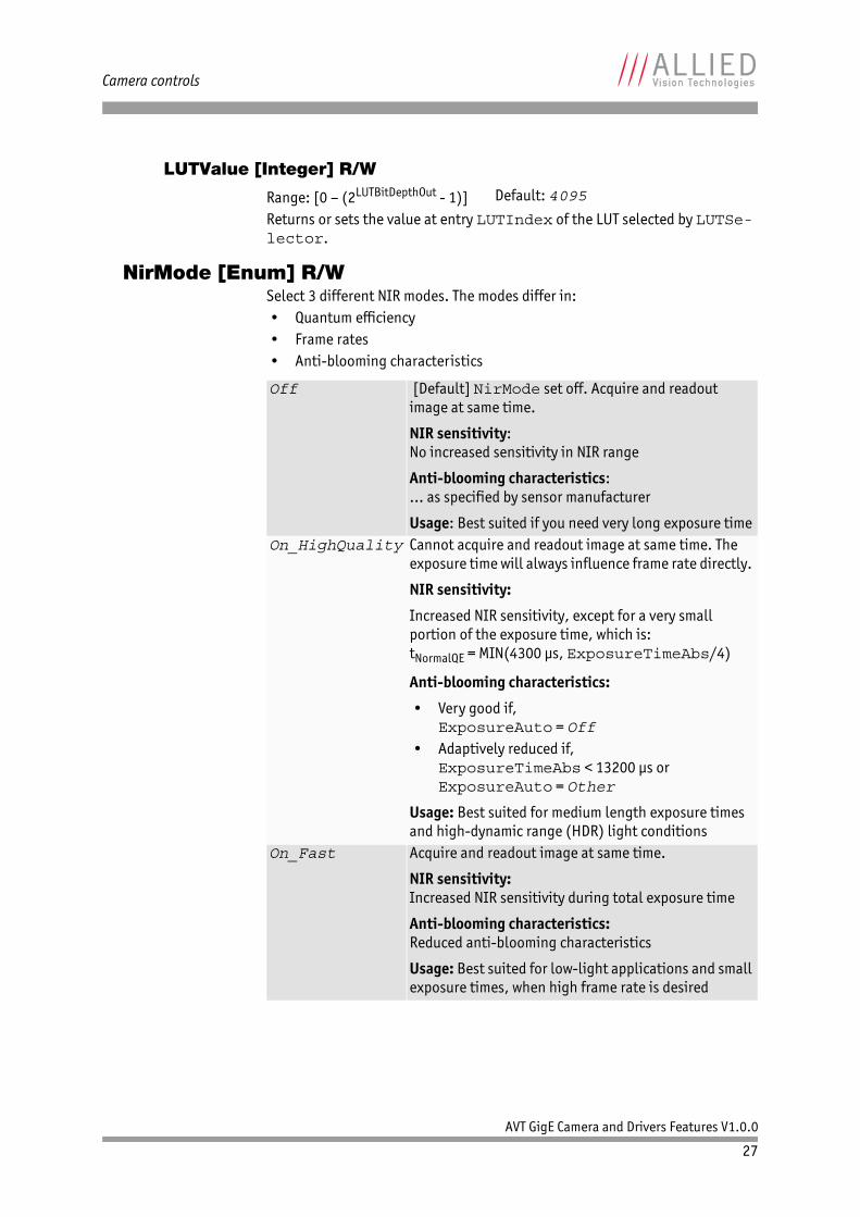
NirMode [Enum] R/WSelect 3 different NIR modes. The modes differ in: • Quantum efficiency• Frame rates • Anti-blooming characteristics
Range: [0 – (2LUTBitDepthOut - 1)] Default: 4095
Off [Default] NirMode set off. Acquire and readout image at same time.
NIR sensitivity:No increased sensitivity in NIR range
Anti-blooming characteristics:... as specified by sensor manufacturer
Usage: Best suited if you need very long exposure timeOn_HighQuality Cannot acquire and readout image at same time. The
exposure time will always influence frame rate directly.
NIR sensitivity:
Increased NIR sensitivity, except for a very small portion of the exposure time, which is:tNormalQE = MIN(4300 μs, ExposureTimeAbs/4)
Anti-blooming characteristics:
• Very good if,ExposureAuto = Off
• Adaptively reduced if,ExposureTimeAbs < 13200 μs orExposureAuto = Other
Usage: Best suited for medium length exposure times and high-dynamic range (HDR) light conditions
On_Fast Acquire and readout image at same time.
NIR sensitivity:Increased NIR sensitivity during total exposure time
Anti-blooming characteristics:Reduced anti-blooming characteristics
Usage: Best suited for low-light applications and small exposure times, when high frame rate is desired
AVT GigE Camera and Drivers Features V1.0.0
27
Camera controls
Saturation [Float] R/W
Alters color intensity. Applied post-Bayer interpolation. Only available on color PixelFormats noted with on-camera interpolation.
SubstrateVoltage
VsubValue [Integer] R/W
CCD substrate voltage. Optimized at factory for each sensor.
Whitebalance
BalanceRatioAbs [Float] R/W
Adjusts the gain of the channel selected in the BalanceRatioSelector. BalanceRatioAbs = 1.00 means no gain is applied.
BalanceRatioSelector [Enum] R/W
Select the Red or Blue channel to adjust with BalanceRatioAbs.
BalanceWhiteAuto [Enum] R/WAuto algorithms use information from the camera’s current image and apply the following settings to the next image; i.e., the camera must be acquiring images in order for the auto algorithm to update. Large changes in scene lighting may require 2-3 frames for the algorithm to stabilize.
You can configure the auto white balance feature to respond only to a subregion within the image scene. This subregion can be configured with the DSPSub-region feature.f
Range: [0.00 – 2.00]
0.00 Monochrome1.00 [Default] Default saturation2.00 Maximum possible saturation that can be applied
Range: [Camera dependent] Units: mV
Range: [Camera dependent]
Note
The green channel gain is always 1.00, as this is the lumi-nance/reference channel. To increase/decrease green, decrease/increase red and blue accordingly.
Possible values: Red, Blue Default: Red
Off [Default] Auto white balance is off. White balance can be adjusted directly by changing the BalanceRatioSe-lector and BalanceRatioAbs
Once A single iteration of the auto white balance algorithm is run, and then BalanceWhiteAuto returns to Off. The Once function operates according to the ExposureAuto and DSPSubregion controls
AVT GigE Camera and Drivers Features V1.0.0
28
Camera controls
BalanceWhiteAutoControl
BalanceWhiteAutoAdjustTol [Integer] R/W
Tolerance allowed from the ideal white balance values, within which the auto white balance does not run. It is used to limit white balance setting changes to only larger variations in color.
BalanceWhiteAutoRate [Integer] R/W
Rate of white balance adjustments, from 1 (slowest) to 100 (fastest). It is used to slow the rate of color balance change so that only longer period fluctuations affect color.
DeviceStatusDeviceTemperature [Float] R
Camera internal temperature.
DeviceTemperatureSelector [Enum] R/W
Selects the site whose temperature is reported by DeviceTemperature.
Continuous White balance will continuously adjust according to the current scene. The continuous function operates according to the ExposureAuto and DSPSubregion controls
Range: [0 – 50] Default: 5 Units: Percent
Range: [1 – 100] Default: 100 Units: Percent
Units: Degree Celsius
Possible values: Main, Sensor
AVT GigE Camera and Drivers Features V1.0.0
29
Camera controls
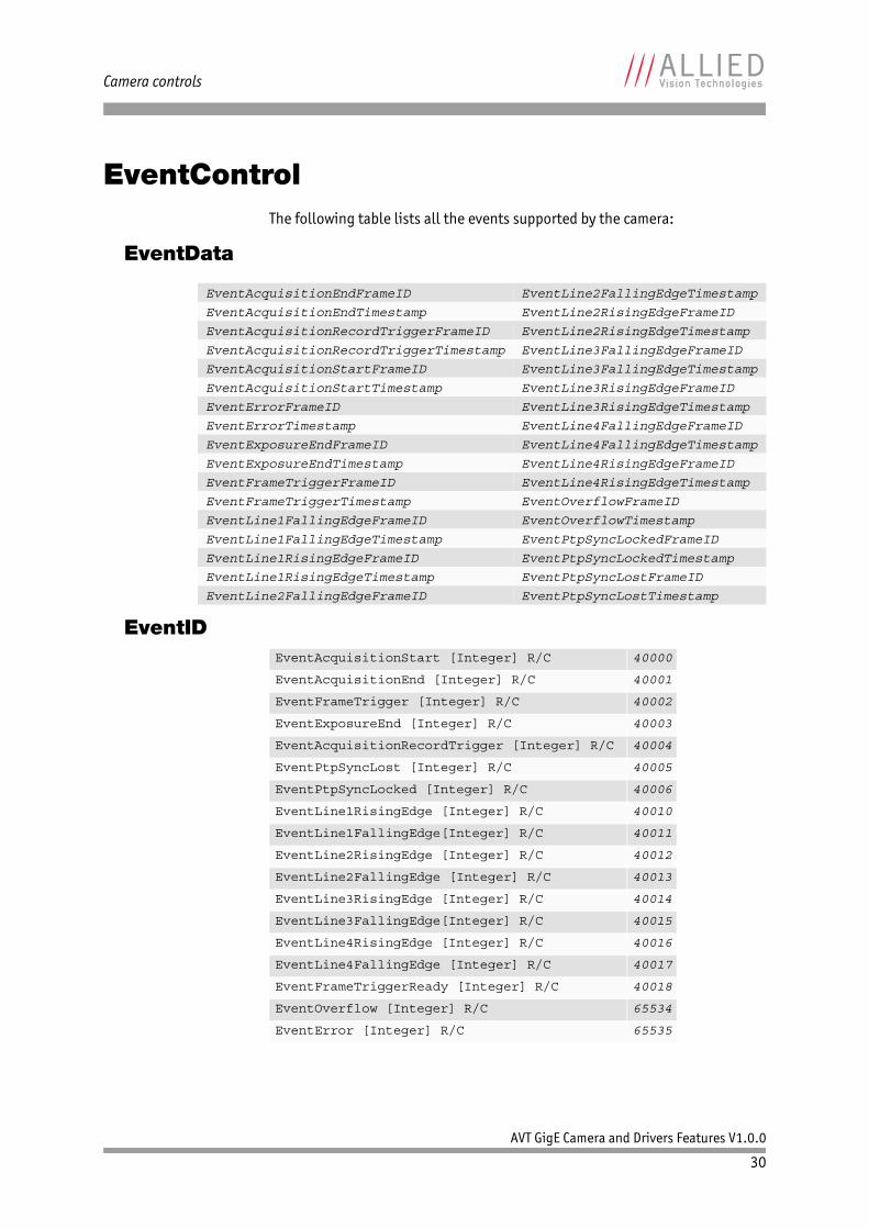
EventControlThe following table lists all the events supported by the camera:
EventData
EventID
EventAcquisitionEndFrameID EventLine2FallingEdgeTimestamp
EventAcquisitionEndTimestamp EventLine2RisingEdgeFrameID
EventAcquisitionRecordTriggerFrameID EventLine2RisingEdgeTimestamp
EventAcquisitionRecordTriggerTimestamp EventLine3FallingEdgeFrameID
EventAcquisitionStartFrameID EventLine3FallingEdgeTimestamp
EventAcquisitionStartTimestamp EventLine3RisingEdgeFrameID
EventErrorFrameID EventLine3RisingEdgeTimestamp
EventErrorTimestamp EventLine4FallingEdgeFrameID
EventExposureEndFrameID EventLine4FallingEdgeTimestamp
EventExposureEndTimestamp EventLine4RisingEdgeFrameID
EventFrameTriggerFrameID EventLine4RisingEdgeTimestamp
EventFrameTriggerTimestamp EventOverflowFrameID
EventLine1FallingEdgeFrameID EventOverflowTimestamp
EventLine1FallingEdgeTimestamp EventPtpSyncLockedFrameID
EventLine1RisingEdgeFrameID EventPtpSyncLockedTimestamp
EventLine1RisingEdgeTimestamp EventPtpSyncLostFrameID
EventLine2FallingEdgeFrameID EventPtpSyncLostTimestamp
EventAcquisitionStart [Integer] R/C 40000
EventAcquisitionEnd [Integer] R/C 40001
EventFrameTrigger [Integer] R/C 40002
EventExposureEnd [Integer] R/C 40003
EventAcquisitionRecordTrigger [Integer] R/C 40004
EventPtpSyncLost [Integer] R/C 40005
EventPtpSyncLocked [Integer] R/C 40006
EventLine1RisingEdge [Integer] R/C 40010
EventLine1FallingEdge[Integer] R/C 40011
EventLine2RisingEdge [Integer] R/C 40012
EventLine2FallingEdge [Integer] R/C 40013
EventLine3RisingEdge [Integer] R/C 40014
EventLine3FallingEdge[Integer] R/C 40015
EventLine4RisingEdge [Integer] R/C 40016
EventLine4FallingEdge [Integer] R/C 40017
EventFrameTriggerReady [Integer] R/C 40018
EventOverflow [Integer] R/C 65534
EventError [Integer] R/C 65535
AVT GigE Camera and Drivers Features V1.0.0
30
Camera controls
EventNotification [Enum] R/W
Activates event notification on the GigE Vision message channel.
EventSelector [Enum] R/WSelects a specific event to be enabled or disabled using EventNotifica-tion. Possible values are listed as following:
EventsEnable1 [Integer] R/WDefault: 0. Bit field of all events. For example:
This is an alternative to setting each event individually using the EventNo-tification and EventSelector method.
Note
If you use the message channel for event notifica-tion, you are always subscribed to EventOver-flow and EventError events.
Note
• There is no mechanism to detect the loss of
events during transportation.• If misconfigured, cameras may produce lots of
events—more than a PC can handle.
Possible values: On, Off Default: Off
AcquisitionStart [Default] AcquisitionEndFrameTrigger ExposureEndAcquisitionRecordTrigger PtpSyncLostPtpSyncLocked Line1RisingEdgeLine1FallingEdge Line2RisingEdgeLine2FallingEdge Line3RisingEdgeLine3FallingEdge Line4RisingEdgeLine4FallingEdge FrameTriggerReady
Bit 1 EventAcquisitionStartBit 2 EventAcquisitionEndBit 3 EventFrameTriggerBit 19 EventFrameTriggerReady
AVT GigE Camera and Drivers Features V1.0.0
31
Camera controls
GigEBandwidthControlMode [Enum] R/W
Selects the desired mode of bandwidth control.
ChunkModeActive [Boolean] R/W
Enables camera to send GigE Vision Standard Protocol chunk data with an image. Currently implemented chunk data:
NonImagePayloadSize [Integer] R
Maximum size of chunk data, not including the image chunk, in the image block payload. If ChunkModeActive = False, NonImagePayloadSize = 0.
PayloadSize [Integer] R
Total size of payload in bytes. • If ChunkModeActive = True:
PayloadSize = ImageSize + NonImagePayloadSize + 8• If ChunkModeActive = False:
PayloadSize = ImageSize
StreamBytesPerSecond [Default] See the StreamBytesPerSec-ond feature for more information
SCPD Stream channel packet delay expressed in timestamp counter units. This mode may be used to limit the rate of data from the camera to the host. It works by inserting a delay between successive stream channel packets, e.g. the longer the delay, the slower the data rate. This mode is NOT recommended
Both Implements a combination of control modes.This mode is NOT recommended
Possible values: True, False Default: False
[Bytes 1 – 4] acquisition count [Bytes 25 – 28] reserved; 0[Bytes 5 – 8] reserved; 0 [Bytes 29 – 32] reserved; 0[Bytes 9 – 12] exposure value [Bytes 33 – 36] reserved; 0[Bytes 13 – 16] gain value [Bytes 37 – 40] reserved; 0[Bytes 17 – 18] sync in levels [Bytes 41 – 44] chunk ID; 1000[Bytes 19 – 20] sync out levels [Bytes 45 – 48] chunk lengthBytes 21 – 24] reserved; 0
Units: Bytes
Units: Bytes
AVT GigE Camera and Drivers Features V1.0.0
32
Camera controls
StreamBytesPerSecond [Integer] R/W
Moderates the data rate of the camera. This is particularly useful for slowing the camera down so that it can operate over slower links such as Fast Ethernet (100-speed), or wireless networks. It is also an important control for multi-camera situations. When multiple cameras are connected to a single Gigabit Ethernet port (usually through a switch), StreamBytesPerSecond for each camera needs to be set to a value so that the sum of each camera’s StreamBytes-PerSecond parameter does not exceed the data rate of the GigE port. Setting the parameter in this way will ensure that multiple camera situations work with-out packet collisions, i.e. data loss.
To calculate the required minimum StreamBytesPerSecond setting for a camera in any image mode, use the following formula:
StreamBytesPerSecond = Height x Width x FrameRate x Bytes per Pixel
115,000,000 is the typical maximum data rate for a GigE port. Beyond this set-ting, some network cards will drop packets.
StreamFrameRateConstrain [Boolean] R/W
When True, camera automatically limits frame rate to bandwidth, determined by StreamBytesPerSecond, to prevent camera buffer overflows and dropped frames. If False, frame rate is not limited to bandwidth – only sensor readout time. Latter case is useful for AcquisitionMode = Recorder or StreamHoldEnable = On modes, as these modes are not bandwidth lim-ited.
StreamHoldNormally, the camera sends data to the host computer immediately after com-pletion of exposure. Enabling StreamHold delays the transmission of data, storing it in on-camera memory, until StreamHold is disabled.This feature can be useful to prevent GigE network flooding in situations where a large number of cameras connected to a single host computer are capturing a single event. Using the StreamHold function, each camera will hold the event image data until the host computer disables StreamHold for each cam-era in turn.
Range: [1,000,000 – 124,000,000 (248,000,000 for GX in LAG mode)] Units: Bytes/s
Note
If you are seeing occasional frames/packets reported as StatFramesDropped/StatPacketsMissed you will likely need to decrease this parameter.
Possible values: True, False Default: True
AVT GigE Camera and Drivers Features V1.0.0
33
Camera controls
StreamHoldCapacity [Integer] R
The maximum number of images (for the current size and format), which can be stored on the camera when StreamHold is enabled. Used in Acquisi-tionMode = Recorder, or StreamHoldEnable = On. This value is dif-ferent for each camera depending on the camera internal memory size and the ImageSize.
StreamHoldEnable [Enum] R/WControl on-camera image storage; this control is like a “pause” button for the image stream.
TimestampAVT GigE cameras have a very accurate timestamp function for timestamping images.
GevTimestampControlLatch [Command]Captures timestamp and stores in GevTimestampValue.
GevTimestampControlReset [Command]Resets the camera’s timestamp to 0. Not possible when PtpMode = Master or Slave.
GevTimestampTickFrequency [Integer] R
Frequency of image timestamp. The image timestamp can be useful for deter-mining whether images are missing from a sequence due to missing trigger events. Cameras offering clock synchronization via PTP will have a GevTime-StampTickFrequency of 1,000,000,000.
GevTimestampValue [Integer] R
Value of timestamp, when latched by GevTimestampControlLatch.
Units: Frames
On Images remain stored on the camera, and are not transmitted to the host
Off [Default] The image stream resumes, and any stored images are sent to the host
Note
Use PTP for synchronizing cameras.
Range: [0 - 4294967295] Default: Camera dependent Units: Hz
Units: Camera clock ticks
AVT GigE Camera and Drivers Features V1.0.0
34
Camera controls
IOThe control and readout of all camera inputs and outputs. The number of inputs and outputs is camera model dependent.
StatusLED
StatusLedLevels [Integer] R/W
Status led levels in GPO mode.
StatusLedPolarity [Enum] R/W
Polarity applied to the status led specified by StatusLedSelector.
StatusLedSelector [Enum] R/W
Select the status led to be controlled with StatusLedSource and Statu-sLedPolarity.
StatusLedSource [Enum] R/WSignal source of the status led specified by StatusLedSelector.
Range: [0 - 4294967296] Default: 0
Note
StatusLedPolarity can invert these values.
Possible values: Normal, Invert
Possible values: StatusLed1
GPO General purpose output
AcquisitionTriggerReady Active once the camera has been recognized by the host PC and is ready to start acquisition
FrameTriggerReady Becomes active when the camera is in a state that will accept the next frame trigger
FrameTrigger This is the logic trigger signal inside of the camera. It is initiated by an external trigger or software trigger
Exposing [Default] Exposure in progress
FrameReadout Becomes active at the start of frame readout
Imaging Exposing or frame readout. Active when the camera is exposing or reading out frame data
Acquiring Becomes active at the start of acquisition
LineIn1/2/3/4 External input Line1/2/3/4
CCDTemperatureOK Only for cameras that support this feature: indicates if camera has reached the desired temperature value
Strobe1 Source is strobe timing unit
AVT GigE Camera and Drivers Features V1.0.0
35
Camera controls
StrobeDefinition Strobe is an internal signal generator for on-camera clocking functions. Valid
when any of the SyncOutSource is set to Strobe1. Strobe allows the added functionality of duration and delay, useful when trying to sync a camera exposure to an external strobe.
StrobeDelay [Integer] R/W
Delay from strobe trigger to strobe output.
StrobeDuration [Integer] R/W
Duration of strobe signal.
StrobeDurationMode [Enum] R/WMode of the strobe timing unit.
StrobeSource [Enum] R/WAssociates the start of strobe signal with one of the following image capture events:
Range: [0 - Camera dependent] Default: 0 Units: μs
Range: [0 - Camera dependent] Default: 0 Units: μs
Source [Default] Strobe duration is the same as source durationControlled Strobe duration is set by StrobeDuration
AcquisitionTriggerReady Active once the camera has been recognized by the host PC and is ready to start acquisition
FrameTriggerReady Active when the camera is in a state that will accept the next frame trigger
FrameTrigger [Default] Active when an image has been initiated to start. This is the logic trigger signal inside of the camera. It is initiated by an external trigger or software trigger
Exposing Active for the duration of sensor exposure
FrameReadout Active for the duration of frame readout, i.e. the transferring of image data from the CCD to camera memory
Acquiring Active during the acquisition stream
LineIn1 Active when there is an external trigger at line1
LineIn2 Active when there is an external trigger at line2
LineIn3 Active when there is an external trigger at line3
LineIn4 Active when there is an external trigger at line4
Note
For detailed information see the camera waveform diagrams provided in the camera manuals.
AVT GigE Camera and Drivers Features V1.0.0
36

Camera controls
SyncInSignal source of the strobe timing unit. See SyncOutSource for descrip-tions.
SyncInGlitchFilter [Integer] R/W
Ignores glitches on the SyncIn input line with pulse duration less than set value.
SyncInLevels [Integer] RA 4-bit register where each bit corresponds to a specific SyncIn input. For exam-ple, when this value returns 2 (0010), SyncIn2 is high and all other Sync input signals are low.
SyncInSelector [Enum] R/W
Select the sync-in line to control with SyncInGlitchFilter.
SyncOutUsed for synchronization with other cameras/devices or general purpose out-puts.
SyncOutLevels [Integer] R/WOutput levels of hardware sync outputs, for output(s) in GPO mode.
SyncOutPolarity [Enum] R/W
Polarity applied to the sync-out line specified by SyncOutSelector.
SyncOutSelector [Enum] R/W
Selects the sync-out line to control with SyncOutSource, SyncOutPo-larity.
Range: [0 – 50000] Default: 0 Units: ns
Note
Setting SyncInGlitchFilter value increases latency of FrameTrigger by same amount.
Possible values: SyncIn1, SyncIn2, SyncIn3, SyncIn4 Default: SyncIn1
Note
SyncOutPolarity can invert the SyncOutLevels.
Possible values: Normal, Invert Default: Normal
Possible values: SyncOut1, SyncOut2, SyncOut3, SyncOut4Default: SyncOut1
AVT GigE Camera and Drivers Features V1.0.0
37
Camera controls
SyncOutSource [Enum] R/WSignal source of the sync-out line specified by SyncOutSelector.
ImageFormatHeight [Integer] R/W
Height of image.
HeightMax [Integer] RMaximum image height for the current image mode.
ImageSize [Integer] RSize of images, in bytes, for the current format and size.
GPO General purpose output
AcquisitionTriggerReady Active once the camera has been recognized by the host PC and is ready to start acquisition
FrameTriggerReady Active when the camera is in a state that will accept the next frame trigger
FrameTrigger Active when an image has been initiated to start. NOTE: this pulse is too short to be seen on the camera SyncOut1/2/3/4 output. Do not use!
Exposing Active for the duration of sensor exposure
FrameReadout Active during frame readout, i.e. the transferring of image data from the CCD to camera memory
Imaging Active when the camera is exposing or reading out frame data
Acquiring Active when acquisition start has been initiated
LineIn1 Active when there is an external trigger at Line1
LineIn2 Active when there is an external trigger at Line2
LineIn3 Active when there is an external trigger at Line3
LineIn4 Active when there is an external trigger at Line4
Strobe1 The output signal is controlled according to Strobe1 settings
CCDTemperatureOK Only for cameras that support this feature: indicates if camera has reached the desired temperature value
Note
For detailed information see the camera waveform diagrams provided in the camera manuals.
Range: [Camera dependent] Units: Pixels
AVT GigE Camera and Drivers Features V1.0.0
38

Camera controls
OffsetX [Integer] R/W
Starting column of the readout region (relative to the first column of the sen-sor) in pixels.
OffsetY [Integer] R/W
Starting row of the readout region (relative to the first row of the sensor) in pix-els.
PixelFormat [Enum] R/WThere are various pixel data formats that AVT GigE cameras can output. Not all cameras have every mode (see the Technical Manuals for details):
Range: [0 - Camera dependent] Default: 0 Units: Pixels
Range: [0 - Camera dependent] Default: 0 Units: Pixels
Mono8 8 bits per pixel, monochrome. On-camera interpolation, with luminance (Y) channel returned, one pixel every byte.
Mono10 10 bits per pixel, monochrome. On-camera interpolation, with luminance (Y) channel returned, one pixel every two bytes, LSB aligned.
Mono12 12 bits per pixel, monochrome. On-camera interpolation, with luminance (Y) channel returned, one pixel every two bytes, LSB aligned.
Mono12Packed 12 bits per pixel. 2 pixels of data every 3 bytes. Monochrome. (Firmware 1.44 or greater). Doesn’t support odd Width x Height.
Mono14 14 bits per pixel, monochrome. On-camera interpolation, with luminance (Y) channel returned. Data is least significant bit aligned within a 16-bit unsigned integer, e.g. for 14-bit camera: 00xxxxxx xxxxxxxx.
BayerGB8 8 bits per pixel, un-interpolated color.
BayerRG8 8 bits per pixel, un-interpolated color.
BayerGR8 8 bits per pixel, un-interpolated color.
BayerBG8 8 bits per pixel, un-interpolated color.
BayerBG10 10 bits per pixel, un-interpolated color, one pixel every two bytes, LSB aligned.
BayerGB12Packed 12 bits per pixel. 2 pixels of data every 3 bytes. Raw un-interpolated data from camera. (Firmware 1.44 or greater). Doesn’t support odd Width x Height.
BayerGR12Packed 12 bits per pixel. 2 pixels of data every 3 bytes. Raw un-interpolated data from camera. (Firmware 1.44 or greater). Doesn’t support odd Width x Height.
BayerGB12 16 bits per pixel, un-interpolated color. Data is least significant bit aligned within a 16-bit unsigned integer, e.g. for 12-bit camera: 0000xxxx xxxxxxxx.
BayerRG12 16 bits per pixel, un-interpolated color. Data is least significant bit aligned within a 16-bit unsigned integer, e.g. for 12-bit camera: 0000xxxx xxxxxxxx.
BayerGR12 16 bits per pixel, un-interpolated color. Data is least significant bit aligned within a 16-bit unsigned integer, e.g. for 12-bit camera: 0000xxxx xxxxxxxx.
AVT GigE Camera and Drivers Features V1.0.0
39

Camera controls
Width [Integer] R/W
Width of image, in pixels.
WidthMax [Integer] RMaximum image width for the current image mode. Horizontal binning, for example, will change this value.
ImageModeThis camera control provides the binning and the decimation (sub-sampling) features.
Definition Binning is the summing of charge of adjacent pixels on a sensor, giving a lower resolution image, but at full region of interest. Image sensitivity is also improved due to summed pixel charge. AVT's GigE CCD cameras have indepen-dent x, y binning.
BinningHorizontal [Integer] R/W
The horizontal binning factor.
RGB8Packed 24 bits per pixel, on-camera interpolated color. Data sent as three consecutive bytes, representing R, G, B of a pixel.
BGR8Packed 24 bits per pixel, on-camera interpolated color. Data sent as three consecutive bytes, representing B, G, R of a pixel.
RGBA8Packed 32 bits per pixel, on-camera interpolated color. Data sent as four consecutive bytes, representing R, G, B and Alpha channel.
BGRA8Packed 32 bits per pixel, on-camera interpolated color. Data sent as four consecutive bytes, representing R, G, B and Alpha channel.
RGB12Packed 48 bits per pixel, on-camera interpolation. Each value of Red, Green and Blue component is LSB-aligned in a 16 bit value.
YUV411Packed Data sent in YUV format. On-camera interpolated color. (12 bits per pixel), 4 pixel every 6 byte.
YUV422Packed Data sent in YUV format. On-camera interpolated color. (16 bits per pixel), 3 pixel every 6 byte.
YUV444Packed Data sent in YUV format. On-camera interpolated color. (24 bits per pixel), 2 pixel every 6 byte.
Range: [Camera dependent] Units: Pixels
Note
Although binning is possible with color cameras, color information is lost due to summing of different colored pixels on the Bayer filter array.
Range: [1 – Camera dependent] Default: 1
AVT GigE Camera and Drivers Features V1.0.0
40

Camera controls
BinningVertical [Integer] R/W
The vertical binning factor.
DecimationHorizontal [Integer] R/W
Horizontal sub-sampling of the image. This reduces the horizontal resolution (width) of the image by the specified horizontal decimation factor.No increase in the frame rate.
DecimationVertical [Integer] R/W
Vertical sub-sampling of the image. This reduces the vertical resolution (width) of the image by the specified vertical decimation factor. Increased frame rate.
SensorHeight [Integer] R/CThe total number of pixel rows on the sensor.
SensorWidth [Integer] R/CThe total number of pixel columns on the sensor.
Range: [1 – Camera dependent] Default: 1
Range: [1 – 8] Default: 1
1 Off2 2 out of 4 decimation3/4 2 out of 8 decimation5/6/7/8 2 out of 16 decimation
Range: [1 – 8] Default: 1
1 Off2 2 out of 4 decimation3/4 2 out of 8 decimation5/6/7/8 2 out of 16 decimation
Note
Each combination of vertical binning and horizontal decima-tion or vice versa is possible.
Combination of horizontal binning + horizontal decimation is not possible.
Combination of vertical binning + vertical decimation is not possible.
www
See the application note for more information on the decima-tion process:
http://www.alliedvisiontec.com/fileadmin/content/PDF/Support/Application_Notes/AppNote_-_Decimation.pdf
AVT GigE Camera and Drivers Features V1.0.0
41
Camera controls
InfoDeviceFirmwareVersion [String] R/C
Firmware version of this AVT GigE camera.
DeviceID [String] R/CSerial number of the camera.
DeviceUserID [String] R/WUsed for multiple-camera situations for providing meaningful labels to individ-ual cameras.
DeviceModelName [String] R/WCamera model name, such as Manta G-125C. Software should use the DevicePartNumber to distinguish between models.
DevicePartNumber [String] R/CManufacturer’s part number.
DeviceScanType [Enum] R/CScan type of the camera.
DeviceVendorName [String] R/CManufacturer’s name: Allied Vision Technologies.
FirmwareVerBuild [Integer] R/CBuild information.
FirmwareVerMajor [Integer] R/CMajor part of the firmware version number (part before the decimal).
FirmwareVerMinor [Integer] R/CMinor part of firmware version number (part after the decimal).
SensorBits [Integer] R/CMaximum bit depth of sensor.
SensorType [Enum] R/CType of image sensor. Monochrome or Bayer-pattern color sensor type.
SavedUserSetsAVT GigE cameras are capable of storing a number of user-specified configura-tions within the camera's non-volatile memory. These saved configurations can be used to define the power-up settings of the camera or to quickly switch between a number of predefined settings.
AVT GigE Camera and Drivers Features V1.0.0
42
Camera controls
UserSetDefaultSelector [Enum] R/W
On power-up or reset, this user set is loaded.
UserSetLoad [Command]Loads camera parameters from the user set specified by UserSetSelector.
UserSetSave [Command]Saves camera parameters to the user set specified by UserSetSelector. The Default setting cannot be overwritten.
UserSetSelector [Enum] R/W
Selects a user set, for loading or saving camera parameters.
Note
Only camera features (those features listed in this docu-ment under the Camera controls section) can be saved to a camera UserSets. Driver and LUT features cannot be saved.
To save the content of a LUT, use Controls/LUTCon-trol/LUTSave or LUTSaveAll.
Possible values: Default, UserSet1, UserSet2, UserSet3, UserSet4, UserSet5
Possible values: Default, UserSet1, UserSet2, UserSet3, UserSet4, UserSet5
AVT GigE Camera and Drivers Features V1.0.0
43
Driver controls
Driver controls
Driver controls affect the connection between the driver on the host side and the camera, leading to changes on both sides; whereas, camera controls have no influence on the driver. Driver controls cannot be saved to a camera user set.
GigE
Configuration
GevIPConfigurationMode [Enum] R/W
Current IP configuration mode.
Current
GevCurrentDefaultGateway [Integer] R
IP address of the default Gateway of the device.
GevCurrentIPAddress [Integer] R
Current IP address of the device.
GevCurrentSubnetMask [Integer] R
Current Subnet Mask of the device.
GevDeviceMACAddress [Integer] R
48-bit MAC address of the GVCP interface of the selected remote device.
GVCP Definition GVCP = GigE Vision Control Protocol
AVT GigE cameras have a sophisticated real time resend mechanism that ensures a high degree of data integrity.
GVCPCmdRetries [Integer] R/W
Controls the maximum number of resend requests that the host will attempt when trying to recover a lost packet.
Display name: IP Configuration ModePossible values: LLA, DHCP, Persistent
Display name: Current Default Gateway
Display name: Current IP Address
Display name: Current Subnet Mask
Display name: Device MAC address
Display name: Command RetriesRange:[1-10] Default: 5
AVT GigE Camera and Drivers Features V1.0.0
44
Driver controls
GVCPCmdTimeout [Integer] R/W
Timeout waiting for an answer from the device.
GVCPHBInterval [Integer] R/W
Interval of time at which a heartbeat message should be sent to the device. Nor-mally, this parameter does not require adjustment.
GevSCPSPacketSize [Integer] R/W
This parameter determines the Ethernet packet size. Generally, this number should be set to as large as the network card (or other involved active network-ing components) will allow. If this number is reduced, then CPU loading will increase. These large packet sizes (>1500) are called jumbo packets/frames in Ethernet terminology. If your Gigabit Ethernet network card does not support jumbo packets/frames of at least 8228 Bytes (the camera default on power up), then you will need to reduce GevSCPSPacketSize parameter of the camera to match the maximum jumbo packet size supported by your Gigabit Ethernet interface. A GevSCPSPacketSize of 1500 is a safe setting which all GigE Ethernet network cards support.
PtpPrecision Time Protocol (PTP) manages clock synchronization of multiple devices across an Ethernet network. Once the clocks of devices such as cameras, PCs, and sensors are synchronized, future software based triggers can be syn-chronized within 2 μs. On AVT GigE cameras, the device clock is represented by the camera GevTimeStampValue feature.
Display name: Command Timeout Range:[100-1000] Default: 250 Units: ms
Display name: Heartbeat IntervalRange: [Camera dependent] Units: ms
Note
This parameter can be increased significantly to bypass problems when debugging applications.
Range: [Camera dependent] Default: Camera dependent Units: Bytes
Note
If you are seeing all black images, or all frames reported as StatFramesDropped and zero images reported as StatFramesDelivered, you will likely need to decrease this parameter.
AVT GigE Camera and Drivers Features V1.0.0
45
Driver controls
PtpAcquisitionGateTime [Integer] R/W
PtpAcquisition trigger time. Used to schedule a synchronized software trigger on multiple PTP synchronized device. Must be set beyond current camera GevTimeStampValue. When set, image acquisition stalls. When camera GevTimeStampValue PtpAcquisitionGateTime, image acquisi-tion resumes.
PtpMode [Enum] R/WControls the PTP behavior of the clock port.
PtpStatus [Enum] RState of the PTP operation.
Persistent
GevPersistentDefaultGateway [Integer] R/W
Persistent default gateway of the device.
GevPersistentIPAddress [Integer] R/W
Persistent IP address of the device.
GevPersistentSubnetMask [Integer] R/W
Persistent subnet mask of the device.
Range: [0 – (263-1)] Default: 0 Units: ns
Off [Default] This camera‘s GevTimeStampValue is not synchronized with any other device
Slave This camera‘s GevTimeStampValue is altered to align with a master device‘s clock
Master This camera‘s GevTimeStampValue is the master clock. All other PTP enabled slave devices synchronize their clock to this camera
Auto This camera uses the IEEE1588 best master clock algo-rithm to determine which device is master, and which are slaves. It may be assigned as either
Off [Default] Camera PtpMode set to OffMaster This camera acting as master clockSynching PTP synchronization not yet achieved. Slave(s) are
synching with masterSlave PTP synchronization among devices achieved. This
camera is acting as a slave to another device‘s master clock
Error Synchronization is lost
Display name: Persistent Default Gateway
Display name: Persistent IP Address
Display name: Persistent Subnet Mask
AVT GigE Camera and Drivers Features V1.0.0
46
Driver controls
Stream
Info
GVSPFilterVersion [String] R/C
Version of the GVSP Filter driver.
MulticastMulticast mode allows the camera to send image data to all hosts on the same subnet as the camera. The host computer (or AVT Vimba Viewer application instance) that first enables multicast mode is the master, and controls all cam-era parameters. All other hosts/instances are the monitors, and can view image data only.
MulticastEnable [Boolean] R/W
Enables multicast mode. In multicast mode all computers on the same subnet as the camera can receive image data from the camera MulticastIPAd-dress.
MulticastIPAddress [Integer] R/C
Sets the multicast IP address.
SettingsDefinition GVSP = GigE Vision Streaming Protocol
GVSPAdjustPacketSize [Command]
Requests the packet size used to be adjusted automatically.
GVSPBurstSize [Integer] R/W
Maximum number of GVSP packets to be processed in a burst.
Display name: GVSP Filter Version
Note
Most GigE switches support a maximum PacketSize of 1500 in multicast mode.
Note
When using clients with Linux, you have to configure the IP subsystem to process Multicast IP traffic.
Display name: Multicast EnablePossible values: True, False Default: False
Display name: Multicast IP Address
Display name: GVSP Adjust Packet Size
Display name: GVSP Burst SizeRange: [1 - 256] Default: 32 Units: GVSP Packets
AVT GigE Camera and Drivers Features V1.0.0
47
Driver controls
GVSPDriverSelector [Enum] R/W
Streaming driver to be used.
GVSPHostReceiveBuffers [Integer] R/W
Number of buffers to be used by the network socket. Only applicable when not using the Filter Driver.
GVSPMaxLookBack [Integer] R/W
Size of the look back window, in packets, when determining if a stream packet is missing. When a stream packet arrives out of order, the driver skips back GVSPMaxLookBack packets to see if the packets previous to this point have all arrived. If not, a resend is issued. A lower value allows the driver less time to assemble out-of-order packets; a larger value allows the driver more time. If the value is set too low, the driver will issue unnecessary resends. If the value is set too high and a packet truly is missing, the driver will issue a resend but the cam-era may no longer have the required packet in its resend buffer and the packet will be dropped. The ideal value is system dependent.
GVSPMaxRequests [Integer] R/W
The maximum number of resend requests that the host will attempt before marking a packet dropped.
GVSPMaxWaitSize [Integer] R/W
Maximum number of received GVSP packets following a resend request to wait before requesting again.
GVSPMissingSize [Integer] R/W
Maximum number of simultaneous missing GVSP packets before dropping the frame (0 = OFF).
GVSPPacketSize [Integer] R/W
GVSP Packet size.
Display name: GVSP Driver SelectorPossible values: Filter, Socket Default: Filter
Display name: GVSP Host Receive Buffers
Range: [256 – 2048] Default: 512
Display name: GVSP Max Look Back Range: [1 – 1024] Default: 30
Display name: GVSP Max RequestsRange: [1 – 512] Default: 3
Display name: GVSP Max Wait SizeRange: [8 – 1024] Default: 100
Display name: GVSP Missing Size Range: [0 – 1024] Default: 512
Display name: GVSP Packet SizeRange: [Camera dependent] Default: Camera dependent Units: Bytes
AVT GigE Camera and Drivers Features V1.0.0
48
Driver controls
GVSPTiltingSize [Integer] R/W
Maximum number GVSP packets received from a following frame before drop-ping the frame (0 = OFF).
GVSPTimeout [Integer] R/W
End of stream timeout. If no stream packet received before GVSPTimeout, host requests resend, up to GVSPMaxRequests times. If still no packet received from camera, packet is marked as dropped.
Statistics
StatFrameRate [Float] R
The current actual frame rate of the camera as received by the driver.
StatFramesDelivered [Integer] R
The number of frames captured since the start of imaging.
StatFramesDropped [Integer] R
Number of frames dropped by the streaming engine due to missing packets.
StatFramesRescued [Integer] R
Number of frames successfully delivered by the streaming engine after having had missing packets.
StatFramesShoved [Integer] R
Number of frames dropped because a following frame was completed before.
StatFramesUnderrun [Integer] R
Number of frames missed due to the non-availability of a user supplied buffer.
StatLocalRate [Float] R
Rate at which the streaming engine is processing the frames sent by the device (frame/s).
Display name: GVSP Tilting Size
Range: [0 – 1024] Default: 100
Display name: GVSP Timeout Range: [10 – 5000] Default: 70 Units: ms
Note
The packet counts in these statistics cover the image transport. Packets used for camera control or event data are not counted. All counters are reset at AcquisitionStart.
Display name: Stat Frame Rate
Display name: Stat Frames Delivered
Display name: Stat Frames Dropped
Display name: Stat Frames Rescued
Display name: Stat Frames Shoved
Display name: Stat Frames Underrun
Display name: Stat Local Rate
AVT GigE Camera and Drivers Features V1.0.0
49
Driver controls
StatPacketsErrors [Integer] R
The number of improperly formed packets. If this number is non-zero, it sug-gests a possible cable or camera hardware failure.
StatPacketsMissed [Integer] R
The number of packets missed since the start of imaging.
StatPacketsReceived [Integer] R
Indicates the number of packets received by the driver since the start of imag-ing, this number should grow steadily during continuous acquisition.
StatPacketsRequested [Integer] R
When an expected packet is not received by the driver, it is recognized as miss-ing and the driver requests the camera to resend it. The resend mechanism ensures very high data integrity.
StatPacketsResent [Integer] R
The number of packets resent by the camera since the start of imaging.
StatTimeElapsed [Float] R
Elapsed time (in seconds) since the streaming was started.
Display name: Stat Packets Errors
Display name: Stat Packets Missed
Note
If everything is configured correctly, this number should remain zero, or at least very low compared to StatPacketsReceived.
Display name: Stat Packets Received
Display name: Stat Packets Requested
Note
If everything is configured correctly, this number should remain zero, or at least very low compared to StatPacketsReceived.
Display name: Stat Packets Resent
Display name: Stat Time Elapsed
AVT GigE Camera and Drivers Features V1.0.0
50
Index
Index
AAcqStartTriggerMode ................................ 12Acquiring ..................................... 35, 36, 38Acquisition ............................................. 11AcquisitionAbort ..................................... 11AcquisitionEnd ........................................ 14AcquisitionFrameCount ........................ 11, 12AcquisitionFrameRateAbs ..................... 13, 14AcquisitionMode ....................... 11, 12, 33, 34AcquisitionRecord ............................... 12, 14AcquisitionStart ................................. 12, 14AcquisitionStop ....................................... 12AcquisitionTriggerReady ................. 35, 36, 38Anti-blooming characteristics .................... 27AnyEdge ................................................ 13AquisitionFrameCount .............................. 12AquisitionFrameRateAbs ........................... 11AquisitionFrameRateLimit ......................... 11AutoOnce .......................................... 17, 28BBalanceRatioAbs ...................................... 28BalanceRatioSelector ............................... 28BalanceWhiteAuto ................................... 28BalanceWhiteAutoAdjustTol ....................... 29BalanceWhiteAutoControl .......................... 29BalanceWhiteAutoRate ............................. 29BandwidthControlMode ............................. 32Bayer12Packed
(Firmware 1.44 or greater) ................... 39Bayer16 ................................................. 39Bayer8 ................................................... 39Binning (definition) ................................. 40BinningHorizontal ................................... 40BinningVertical ....................................... 41BlackLevel .............................................. 14BlackLevelControl .................................... 14BlackLevelSelector ................................... 14CCCDTemperatureOK ......................... 15, 35, 38ChunkModeActive .................................... 32color transformation (definition) ................ 15ColorTransformationControl ....................... 15ColorTransformationMode ......................... 15ColorTransformationSelector ...................... 15
ColorTransformationValue ......................... 15ColorTransformationValueSelector .............. 15Configuration .......................................... 44contact data ............................................. 6Continuous ............................................. 11Current .................................................. 44DDCIris .................................................... 23DecimationHorizontal ............................... 41DecimationVertical (vertical sub-sampling) ... 41DefectMask ............................................. 17DefectMaskColumnEnable .......................... 17DefectMaskPixelEnable ............................. 17definition
color transformation ........................... 15GigE Vision Streaming Protocol ........ 44, 47
DeviceFirmwareVersion ............................. 42DeviceID ................................................ 42DeviceModelName .................................... 42DevicePartNumber ................................... 42DeviceScanType ....................................... 42DeviceStatus ........................................... 29DeviceTemperature .................................. 29DeviceTemperatureSelector ....................... 29DeviceUserID .......................................... 42DeviceVendorName .................................. 42document history ....................................... 7DSPSubregion .......................... 17, 18, 20, 28DSPSubregionBottom ............................... 16DSPSubregionLeft .................................... 16DSPSubregionRight .................................. 16DSPSubregionTop .................................... 16duration of strobe signal ........................... 36EEthernet packet size ................................. 45EventControl ........................................... 30EventData .............................................. 30EventID ................................................. 30EventNotification ..................................... 31EventSelector ......................................... 31EventsEnable1 ........................................ 31Exposing ...................................... 35, 36, 38Exposure ................................................ 17ExposureAuto ............................... 17, 20, 28
AVT GigE Camera and Drivers Features V1.0.0
51
Index
ExposureAutoAdjustTol ............................. 18ExposureAutoAlg ..................................... 18ExposureAutoControl ........................... 18, 20ExposureAutoMax .......................... 17, 18, 20ExposureAutoMin ..................................... 18ExposureAutoOutliers ............................... 18ExposureAutoRate .................................... 18ExposureAutoTarget ............................ 18, 19ExposureMode .................................... 19, 23ExposureTimeAbs ..................................... 19ExposureValue ........................................ 19external trigger ....................................... 36FFirmwareVerBuild .................................... 42FirmwareVerMajor .................................... 42FirmwareVerMinor .................................... 42FitRange ................................................ 18fixed setup time ....................................... 13FixedRate ............................................... 14FocusTimedFar ........................................ 25FocusTimedNear ...................................... 25FrameRate .............................................. 33FrameReadout ............................... 35, 36, 38FrameStart ......................... 11, 12, 13, 14, 17FrameStartTriggerMode ............................. 11FrameTrigger ........................... 35, 36, 37, 38FrameTriggerReady ................... 13, 35, 36, 38Freerun .................................................. 14GGainAuto ...................................... 17, 20, 23GainAutoAdjustTol ................................... 20GainAutoControl ...................................... 20GainAutoMax .......................................... 21GainAutoMin ........................................... 21GainAutoOutliers ..................................... 21GainAutoRate .......................................... 21GainAutoTarget ....................................... 21GainControl ............................................ 20GainRaw ................................................. 21GainSelector ........................................... 21Gamma .................................................. 21general purpose output (GPO) .................... 38GevCurrentDefaultGateway ........................ 44GevCurrentIPAddress ................................ 44GevCurrentSubnetMask ............................. 44GevIPConfigurationMode ........................... 44GevPersistentDefaultGateway ..................... 46GevPersistentIPAddress ............................. 46GevPersistentSubnetMask .......................... 46
GevSCPSPacketSize .................................. 45GevTimestampControlLatch ........................ 34GevTimestampControlReset ........................ 34GevTimestampTickFrequency ...................... 34GevTimeStampValue ............................ 45, 46GevTimestampValue ................................. 34GigE ................................................. 32, 44GigE switch ............................................. 47GigE Vision Streaming Protocol
definition .................................... 44, 47GPO
general purpose output ....................... 38GVCP ..................................................... 44GVCPCmdRetries ...................................... 44GVCPCmdTimeout ..................................... 45GVCPHBInterval ....................................... 45GVSPAdjustPacketSize ............................... 47GVSPBurstSize ......................................... 47GVSPDriverSelector .................................. 48GVSPFilterVersion .................................... 47GVSPHostReceiveBuffers ........................... 48GVSPMaxLookBack ................................... 48GVSPMaxRequests ............................... 48, 49GVSPMaxWaitSize ..................................... 48GVSPMissingSize ...................................... 48GVSPPacketSize ....................................... 48GVSPTiltingSize ....................................... 49GvspTimeout ........................................... 49HHeight ................................................... 38HeightMax .............................................. 38Hue ....................................................... 22Iimage capture events ................................ 36ImageFormat .......................................... 38ImageMode ............................................ 40ImageSize .................................... 32, 34, 38Imaging ............................................ 35, 38Info ...................................................... 47IO ......................................................... 35IODMode ................................................ 22Iris ....................................................... 22IrisAutoTarget ......................................... 23IrisMode ...................................... 17, 20, 23IrisTimedClose ........................................ 25IrisTimedOpen ......................................... 25IrisVideoLevel ......................................... 23IrisVideoLevelMax .................................... 24IrisVideoLevelMin .................................... 24
AVT GigE Camera and Drivers Features V1.0.0
52

Index
JJumbo Packets ........................................ 45Llegal notice .............................................. 2LensDCIris .............................................. 24LensDrive ............................................... 25LensDriveDuration ................................... 25LensPIris ................................................ 24LensPIrisNumSteps .................................. 24Line1 ..................................................... 14Line2 ..................................................... 14LineIn1 ............................................. 36, 38LineIn2 ............................................. 36, 38LineIn3 ............................................. 36, 38LineIn4 ............................................. 36, 38logic trigger ............................................ 36LUTAddress ............................................. 26LUTBitDepthIn ........................................ 26LUTBitDepthOut ....................................... 26LUTControl ........................................ 25, 43LUTEnable .............................................. 25LUTIndex .......................................... 25, 27LUTInfo ............................................. 26, 28LUTLoad ................................................. 26LUTMode ................................................ 26LUTSave ............................................ 26, 43LUTSaveAll ............................................. 43LUTSelector ....................................... 26, 27LUTSizeBytes .......................................... 26LUTValue ................................................ 27MMean ..................................................... 18Mono12Packed
(Firmware 1.44 or greater) ................... 39Mono8 ................................................... 39Multicast ................................................ 47Multicast mode ........................................ 47MulticastEnable ....................................... 47MulticastIPAddress .................................. 47MultiFrame ............................................. 12NNirMode ................................................. 27NonImagePayloadSize .............................. 32non-volatile memory ................................ 42OOffsetX ................................................... 39OffsetY ................................................... 39on-camera memory .................................. 33
PPayloadSize ............................................ 32Persistent ............................................... 46PIrisAuto ................................. 17, 20, 23, 24PIrisManual ....................................... 23, 24pixel columns on the sensor ....................... 41pixel rows on the sensor ............................ 41PixelFormat ............................................ 39predefined settings .................................. 42Ptp ....................................................... 45PtpAcquisitionGateTime ............................ 46PtpMode ........................................... 34, 46PtpStatus ............................................... 46RRecorder ........................................... 33, 34RecorderPreEventCount ............................ 12SSaturation .............................................. 28SavedUserSets ........................................ 42SCPD ..................................................... 32SensorBits .............................................. 42SensorHeight .......................................... 41SensorType ............................................. 42SensorWidth ........................................... 41Settings ................................................. 47Shutter .................................................. 19SingleFrame ........................................... 11Software ................................................ 14software trigger ....................................... 36start of acquisition ................................... 36start of exposure ..................................... 36start of frame readout ............................... 36StatFrameRate ........................................ 49StatFramesCompleted ............................... 45StatFramesDelivered ................................ 49StatFramesDropped ........................ 33, 45, 49StatFramesRescued .................................. 49StatFramesShoved ................................... 49StatFramesUnderrun ................................ 49Statistics ................................................ 49StatLocalRate ......................................... 49StatPacketsErrors .................................... 50StatPacketsMissed .............................. 33, 50StatPacketsReceived ................................. 50StatPacketsRequested .............................. 50StatPacketsResent ................................... 50StatTimeElapsed ...................................... 50Stream .................................................. 47stream channel packet delay (SCPD) ............ 32
AVT GigE Camera and Drivers Features V1.0.0
53
Index
StreamBytesPerSecond ........................ 32, 33StreamFrameRateConstrain ........................ 33StreamHold ............................................ 33StreamHoldCapacity ............................ 11, 34StreamHoldEnable .............................. 33, 34Strobe ................................................... 36strobe lighting source ............................... 13Strobe1 ........................................ 35, 36, 38StrobeDelay ............................................ 36StrobeDuration ....................................... 36StrobeDurationMode ................................ 36StrobeSource .......................................... 36Styles ...................................................... 8SubstrateVoltage ..................................... 28Symbols ................................................... 8SyncIn ................................................... 37SyncInGlitchFilter .................................... 37SyncInLevels ........................................... 37SyncInSelector ........................................ 37SyncOut ................................................. 37SyncOutLevels ......................................... 37SyncOutPolarity ....................................... 37SyncOutSelector ................................. 37, 38SyncOutSource .............................. 36, 37, 38TTemp6500K ............................................ 15Timestamp ......................................... 32, 34timestamp function .................................. 34Trigger ................................................... 13TriggerActivation ................................ 13, 14TriggerDelayAbs ...................................... 13TriggerMode ...................................... 12, 13TriggerOverlap ........................................ 13TriggerSelector .................... 11, 12, 13, 14, 17TriggerSoftware ....................................... 14TriggerSource ............................... 13, 14, 17UUserSetDefaultSelector ............................. 43UserSetLoad ........................................... 43UserSets ................................................ 26UserSetSave ...................................... 26, 43UserSetSelector ....................................... 43VVideoClosed ............................................ 23VideoOpen .............................................. 23VsubValue .............................................. 28WWhiteBalance .......................................... 28Width .................................................... 40
WidthMax ............................................... 40ZZoomTimedIn .......................................... 25ZoomTimedOut ........................................ 25
AVT GigE Camera and Drivers Features V1.0.0
54