AVS BSR 933 C QE 1-0-0
65
EQUIPMENT MANUAL FOR AVS BSR 933 C AVS BSR 933 C QE Copyright - refer to title page Page 1 ENU Status : 1-0-0 The information contained herein is the responsibility of and is approved by the following, to whom all enquiries should be directed in the first instance: AVS Teknoloji Ltd.Sti Ataturk Cad. Sitki Bey Plaza No:82 D:14 Kozyatagi Istanbul Turkey AVS BSR 933 C GSM 900 DUAL BAND SELECTIVE REPEATER EQUIPMENT MANUAL No part may be reproduced, disclosed or used except as authorised by contract or other written permission. The copyright and the foregoing restriction on reproduction and use extend to all media in which the information may be embodied.
Transcript of AVS BSR 933 C QE 1-0-0
EQUIPMENT MANUAL FOR AVS BSR 933 C
AVS BSR 933 C QE Copyright - refer to title page Page 1 ENU Status : 1-0-0
The information contained herein is the responsibility of and is approved by the following, to whom all enquiries should be directed in the first instance:
AVS Teknoloji Ltd.Sti Ataturk Cad. Sitki Bey Plaza No:82 D:14 Kozyatagi Istanbul Turkey
AVS BSR 933 C GSM 900 DUAL BAND SELECTIVE
REPEATER
EQUIPMENT MANUAL
No part may be reproduced, disclosed or used except as authorised by contract or other written permission. The copyright and the
foregoing restriction on reproduction and use extend to all media in which the information may be embodied.
EQUIPMENT MANUAL FOR AVS BSR 933 C
AVS BSR 933 C QE Copyright - refer to title page Page 2 ENU Status : 1-0-0
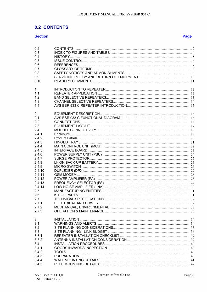
0.2 CONTENTS
Section Page
0.2 CONTENTS....................................................................................................................................... 2 0.3 INDEX TO FIGURES AND TABLES ............................................................................................. 4 0.4 HISTORY ........................................................................................................................................... 5 0.5 ISSUE CONTROL ............................................................................................................................ 6 0.6 REFERENCES ................................................................................................................................. 7 0.7 GLOSSARY OF TERMS ................................................................................................................. 8 0.8 SAFETY NOTICES AND ADMONISHMENTS............................................................................. 9 0.9 SERVICING POLICY AND RETURN OF EQUIPMENT........................................................... 10 0.10 READERS COMMENTS ............................................................................................................... 11
1 INTRODUCTON TO REPEATER ................................................................................................ 12 1.1 REPEATER APPLICATION .......................................................................................................... 12 1.2 BAND SELECTIVE REPEATERS................................................................................................ 13 1.3 CHANNEL SELECTIVE REPEATERS........................................................................................ 14 1.4 AVS BSR 933 C REPEATER INTRODUCTION........................................................................ 15
2 EQUIPMENT DESCRIPTION....................................................................................................... 16 2.1 AVS BSR 933 C FUNCTIONAL DIAGRAM................................................................................ 16 2.2 CONNECTIONS ............................................................................................................................. 16 2.3 EQUIPMENT LAYOUT .................................................................................................................. 17 2.4 MODULE CONNECTIVITY ........................................................................................................... 18 2.4.1 Enclosure ......................................................................................................................................... 19 2.4.2 Product Labels ................................................................................................................................ 20 2.4.3 HINGED TRAY ............................................................................................................................... 21 2.4.4 MAIN CONTROL UNIT (MCU) ..................................................................................................... 22 2.4.5 INTERFACE BOARD ..................................................................................................................... 23 2.4.6 POWER SUPPLY UNIT (PSU)..................................................................................................... 24 2.4.7 SURGE PROTECTOR .................................................................................................................. 25 2.4.8 LI-ION BACK-UP BATTERY......................................................................................................... 25 2.4.9 MICRO-SWITCH ............................................................................................................................ 26 2.4.10 DUPLEXER (DPX) ......................................................................................................................... 27 2.4.11 GSM MODEM ................................................................................................................................. 28 2.4.12 POWER AMPLIFIER (PA)............................................................................................................. 28 2.4.13 FREQUENCY SELECTOR (FS) .................................................................................................. 29 2.4.14 LOW NOISE AMPLIFIER (LNA)................................................................................................... 30 2.5 MANUFACTURING ENTITIES..................................................................................................... 31 2.6 KIT OF PARTS................................................................................................................................ 31 2.7 TECHNICAL SPECIFICATIONS .................................................................................................. 32 2.7.1 ELECTRICAL AND POWER ........................................................................................................ 32 2.7.2 MECHANICAL, ENVIRONMENTAL ............................................................................................ 33 2.7.3 OPERATION & MAINTENANCE ................................................................................................. 33
3 INSTALLATION .............................................................................................................................. 34 3.1 WARNINGS AND ALERTS........................................................................................................... 34 3.2 SITE PLANNING CONSIDERATIONS........................................................................................ 35 3.3 SITE PLANNING - LINK BUDGET .............................................................................................. 36 3.3.1 REPEATER INSTALLATION CHECKLIST ................................................................................ 39 3.3.2 ANTENNA INSTALLATION CONSIDERATION ........................................................................ 39 3.4 INSTALLATION PROCEDURES ................................................................................................. 40 3.4.1 GOODS INWARDS INSPECTION............................................................................................... 40 3.4.2 TOOLS ............................................................................................................................................. 40 3.4.3 PREPARATION .............................................................................................................................. 40 3.4.4 WALL MOUNTING DETAILS ....................................................................................................... 41 3.4.5 POLE MOUNTING DETAILS........................................................................................................ 42
EQUIPMENT MANUAL FOR AVS BSR 933 C
AVS BSR 933 C QE Copyright - refer to title page Page 3 ENU Status : 1-0-0
3.4.6 DRIP-LOOP..................................................................................................................................... 43 3.4.7 EQUIPMENT CONNECTIONS..................................................................................................... 43
4 COMMISSIONING.......................................................................................................................... 44 4.1 MCU LED INDICATORS ............................................................................................................... 44 4.2 EQUIPMENT POWER-UP ............................................................................................................ 44 4.3 REPEATER PC SOFTWARE (RPS) ........................................................................................... 45 4.4 NON-VOLATILE MEMORY .......................................................................................................... 46 4.5 PREPARATION FOR REMOTE CONNECTION OF RPS USING WIRELESS
MODEM ........................................................................................................................................... 47 4.6 CONNECTING RPS TO EQUIPMENT ....................................................................................... 47 4.7 LOCAL COMMISSIONING ........................................................................................................... 49 4.7.1 USING RPS SOFTWARE ............................................................................................................. 49 4.7.2 DESCRIPTION OF PARAMETERS ............................................................................................ 50 4.8 COMMISSIONING PROCEDURES ............................................................................................ 56
5 OPERATION ................................................................................................................................... 57
6 MAINTENANCE.............................................................................................................................. 58
7 APPENDICES ................................................................................................................................. 59 7.1 APPENDIX A: TOOLS ................................................................................................................... 59 7.2 APPENDIX B: VSWR – RETURN LOSS TABLE ...................................................................... 59 7.3 APPENDIX C: UPLINK ATT AND NOISE LEVEL ..................................................................... 59 7.4 APPENDIX D: CHANNEL NUMBER AND FREQUENCY TABLE .......................................... 60 7.5 APPENDIX E: RPS INSTALLATION AND UN-INSTALLATION ............................................. 63
EQUIPMENT MANUAL FOR AVS BSR 933 C
AVS BSR 933 C QE Copyright - refer to title page Page 4 ENU Status : 1-0-0
0.3 INDEX TO FIGURES AND TABLES
Figure 1: Typical Repeater Setup .......................................................................................................12 Figure 2: Band Selective Repeater .....................................................................................................13 Figure 3: GSM Channel Selective Repeater.......................................................................................14 Figure 4: AVS BSR 933 C functional diagram ....................................................................................16 Figure 5: Equipment connections .......................................................................................................16 Figure 6: Layout view of equipped product .........................................................................................17 Figure 7: RF connectivity diagram ......................................................................................................18 Figure 8: Inside view of the equipment ...............................................................................................19 Figure 9: Side view of enclosure showing lock and label ...................................................................19 Figure 10 : CE label ............................................................................................................................20 Figure 11 : Product Identification Label ..............................................................................................20 Figure 12: Front view of hinged tray ...................................................................................................21 Figure 13: Erected hinged tray showing FS and PA...........................................................................21 Figure 14: MCU board.........................................................................................................................22 Figure 15 : MCU relationship diagram ................................................................................................22 Figure 16 : Interface board..................................................................................................................23 Figure 17 : Surge protector for power supply......................................................................................25 Figure 18: Li-ion battery pack..............................................................................................................25 Figure 19 : Location of Microswitch ....................................................................................................26 Figure 20: Duplexer (towards MT Connection) mounted on the hinged tray......................................27 Figure 21: Mounting Rack Dimension.................................................................................................41 Figure 22: Wall Mounting Overview ....................................................................................................42 Figure 23: Pole Mounting Overview....................................................................................................42 Figure 24: Location of MCU and LED .................................................................................................44 Figure 25: RPS Main Screen- RF Parameters....................................................................................45 Figure 26: Wireless modem ................................................................................................................47 Figure 27: RPS Screenshot - Communication Setup .........................................................................47 Figure 28: RPS Screenshot –Online Ok .............................................................................................49 Figure 29: RPS Screenshot- Network Parameter Window.................................................................50 Figure 30: RPS Screenshot: Alarm and Power Window.....................................................................53 Figure 31: RPS Software Version .......................................................................................................55
Table 1: AVS BSR 933 C Manufacturing Entities ...............................................................................31 Table 2: AVS BSR 933 C KOP ...........................................................................................................31 Table 3: Electrical specifications.........................................................................................................32 Table 4: Mechanical and environmental specifications ......................................................................33 Table 5: Management of AVS BSR 933 C..........................................................................................33 Table 6: Repeater Installation checklist ..............................................................................................39 Table 7: Antenna installation checklist................................................................................................39 Table 8: MCU LED ..............................................................................................................................44 Table 9: Management - Network Parameters...................................................................................50 Table 10: Management - RF parameters............................................................................................51 Table 11: Management - Alarm list .....................................................................................................52 Table 12: Commissioning procedures ................................................................................................56 Table 13: Alarms diagnosis.................................................................................................................57

EQUIPMENT MANUAL FOR AVS BSR 933 C
AVS BSR 933 C QE Copyright - refer to title page Page 5 ENU Status : 1-0-0
0.4 HISTORY
Change No. Issue/ENU Details Of Change
1 1-0-0 Initial document created in July 2005
EQUIPMENT MANUAL FOR AVS BSR 933 C
AVS BSR 933 C QE Copyright - refer to title page Page 6 ENU Status : 1-0-0
0.5 ISSUE CONTROL
Date 15 Aug 05
Section All all
EQUIPMENT MANUAL FOR AVS BSR 933 C
AVS BSR 933 C QE Copyright - refer to title page Page 7 ENU Status : 1-0-0
0.6 REFERENCES
0.6.1 ETSI EN 300 609-4 Digital cellular telecommunications system (Phase 2 & Phase
2+); Base Station System (BSS) equipment specification; Part 4: Repeaters (GSM 11.26 version 5.2.0)
0.6.2 OHSAS 18000, BSI 18001, APR 1999 BSI
EQUIPMENT MANUAL FOR AVS BSR 933 C
AVS BSR 933 C QE Copyright - refer to title page Page 8 ENU Status : 1-0-0
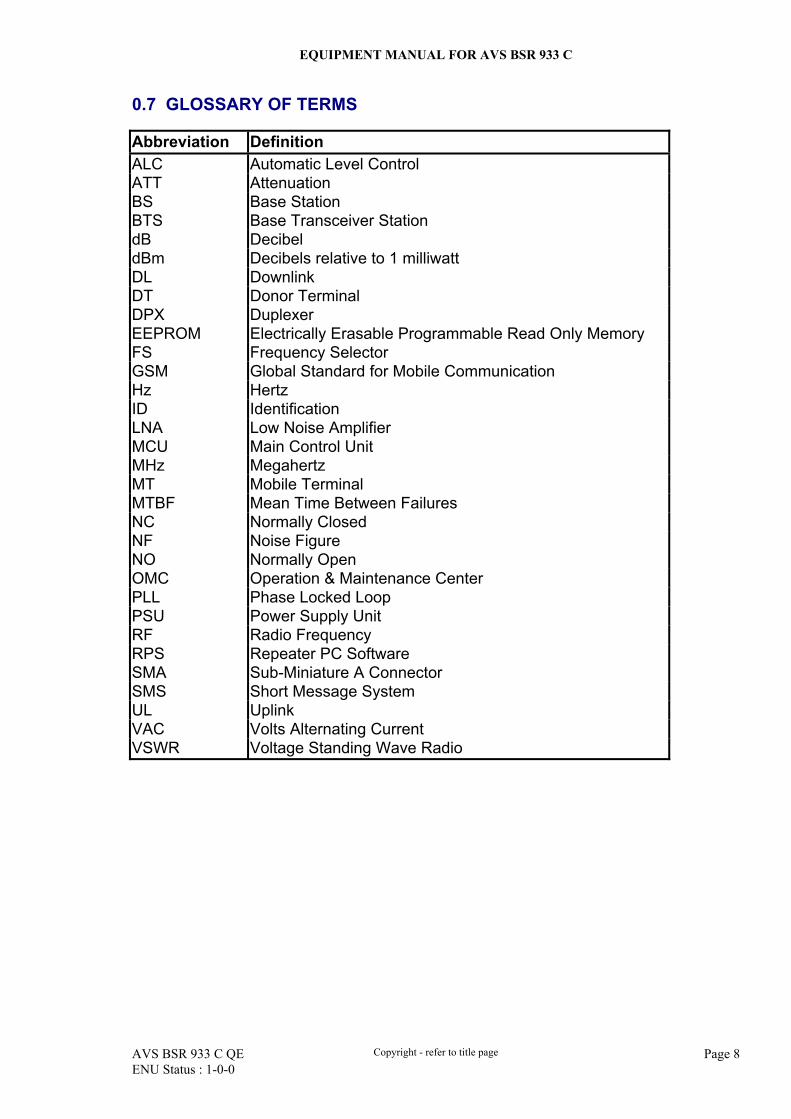
0.7 GLOSSARY OF TERMS
Abbreviation Definition ALC Automatic Level Control ATT Attenuation BS Base Station BTS Base Transceiver Station dB Decibel dBm Decibels relative to 1 milliwatt DL Downlink DT Donor Terminal DPX Duplexer EEPROM Electrically Erasable Programmable Read Only Memory FS Frequency Selector GSM Global Standard for Mobile Communication Hz Hertz ID Identification LNA Low Noise Amplifier MCU Main Control Unit MHz Megahertz MT Mobile Terminal MTBF Mean Time Between Failures NC Normally Closed NF Noise Figure NO Normally Open OMC Operation & Maintenance Center PLL Phase Locked Loop PSU Power Supply Unit RF Radio Frequency RPS Repeater PC Software SMA Sub-Miniature A Connector SMS Short Message System UL Uplink VAC Volts Alternating Current VSWR Voltage Standing Wave Radio
EQUIPMENT MANUAL FOR AVS BSR 933 C
AVS BSR 933 C QE Copyright - refer to title page Page 9 ENU Status : 1-0-0
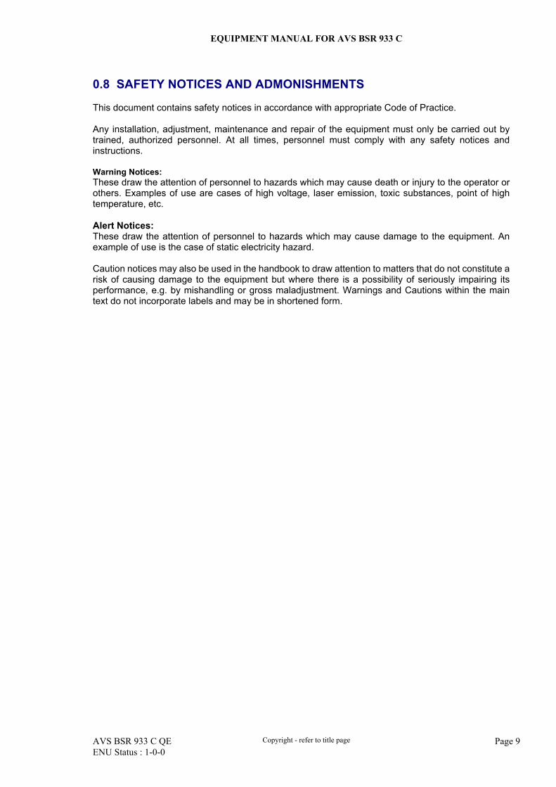
0.8 SAFETY NOTICES AND ADMONISHMENTS
This document contains safety notices in accordance with appropriate Code of Practice. Any installation, adjustment, maintenance and repair of the equipment must only be carried out by trained, authorized personnel. At all times, personnel must comply with any safety notices and instructions. Warning Notices: These draw the attention of personnel to hazards which may cause death or injury to the operator or others. Examples of use are cases of high voltage, laser emission, toxic substances, point of high temperature, etc. Alert Notices: These draw the attention of personnel to hazards which may cause damage to the equipment. An example of use is the case of static electricity hazard. Caution notices may also be used in the handbook to draw attention to matters that do not constitute a risk of causing damage to the equipment but where there is a possibility of seriously impairing its performance, e.g. by mishandling or gross maladjustment. Warnings and Cautions within the main text do not incorporate labels and may be in shortened form.
EQUIPMENT MANUAL FOR AVS BSR 933 C
AVS BSR 933 C QE Copyright - refer to title page Page 10 ENU Status : 1-0-0
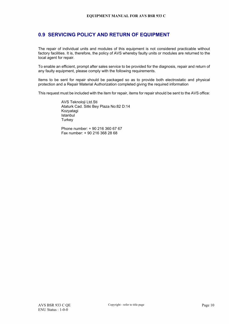
0.9 SERVICING POLICY AND RETURN OF EQUIPMENT
The repair of individual units and modules of this equipment is not considered practicable without factory facilities. It is, therefore, the policy of AVS whereby faulty units or modules are returned to the local agent for repair. To enable an efficient, prompt after sales service to be provided for the diagnosis, repair and return of any faulty equipment, please comply with the following requirements. Items to be sent for repair should be packaged so as to provide both electrostatic and physical protection and a Repair Material Authorization completed giving the required information This request must be included with the item for repair, items for repair should be sent to the AVS office:
AVS Teknoloji Ltd.Sti Ataturk Cad. Sitki Bey Plaza No:82 D:14 Kozyatagi Istanbul Turkey
Phone number: + 90 216 360 67 67 Fax number: + 90 216 368 28 68
EQUIPMENT MANUAL FOR AVS BSR 933 C
AVS BSR 933 C QE Copyright - refer to title page Page 11 ENU Status : 1-0-0
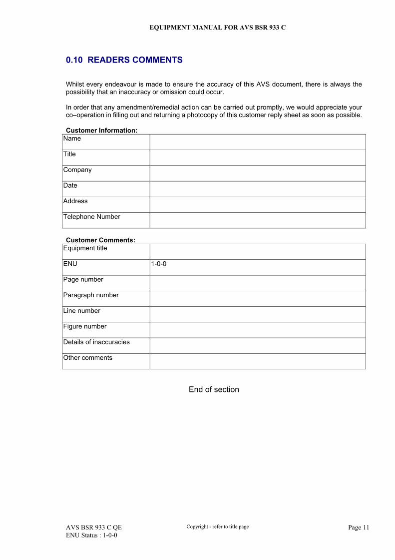
0.10 READERS COMMENTS
Whilst every endeavour is made to ensure the accuracy of this AVS document, there is always the possibility that an inaccuracy or omission could occur. In order that any amendment/remedial action can be carried out promptly, we would appreciate your co–operation in filling out and returning a photocopy of this customer reply sheet as soon as possible. Customer Information:
Name
Title
Company
Date
Address
Telephone Number
Customer Comments:
Equipment title
ENU 1-0-0
Page number
Paragraph number
Line number
Figure number
Details of inaccuracies
Other comments
End of section
EQUIPMENT MANUAL FOR AVS BSR 933 C
AVS BSR 933 C QE Copyright - refer to title page Page 12 ENU Status : 1-0-0
1 INTRODUCTON TO REPEATER
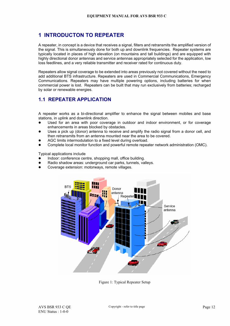
A repeater, in concept is a device that receives a signal, filters and retransmits the amplified version of the signal. This is simultaneously done for both up and downlink frequencies. Repeater systems are typically located in places of high elevation (on mountains and tall buildings) and are equipped with highly directional donor antennas and service antennas appropriately selected for the application, low loss feedlines, and a very reliable transmitter and receiver rated for continuous duty. Repeaters allow signal coverage to be extended into areas previously not covered without the need to add additional BTS infrastructure. Repeaters are used in Commercial Communications, Emergency Communications. Repeaters may have multiple powering options, including batteries for when commercial power is lost. Repeaters can be built that may run exclusively from batteries; recharged by solar or renewable energies. 1.1 REPEATER APPLICATION
A repeater works as a bi-directional amplifier to enhance the signal between mobiles and base stations, in uplink and downlink direction.
Used for an area with poor coverage in outdoor and indoor environment, or for coverage enhancements in areas blocked by obstacles.
Uses a pick up (donor) antenna to receive and amplify the radio signal from a donor cell, and then retransmits from an antenna mounted near the area to be covered.
AGC limits intermodulation to a fixed level during overload. Complete local monitor function and powerful remote repeater network administration (OMC).
Typical applications include
Indoor: conference centre, shopping mall, office building. Radio shadow areas: underground car parks, tunnels, valleys. Coverage extension: motorways, remote villages.
Figure 1: Typical Repeater Setup
EQUIPMENT MANUAL FOR AVS BSR 933 C
AVS BSR 933 C QE Copyright - refer to title page Page 13 ENU Status : 1-0-0
Using a repeater can achieve the following benefits:
Fast rollout and fast coverage leads to fast return on investment Low build out costs For GSM network, no planning of BSS parameter No microwave link and No 2 Mbit- connection needed Less antennas and cable usage, and much lighter steel hardware A strong tower is not required. Easy to locate site for installation & coverage Expands coverage areas in: rural, tunnels, in-building, canyons and highways Platform for subscriber growth
AVS repeater types include:
Broadband repeater Band-selective repeater Channel-selective repeater Fiber-optic repeater Frequency-shifting repeater
In this manual we will focus on AVS BSR 933 C band selective repeater. 1.2 BAND SELECTIVE REPEATERS
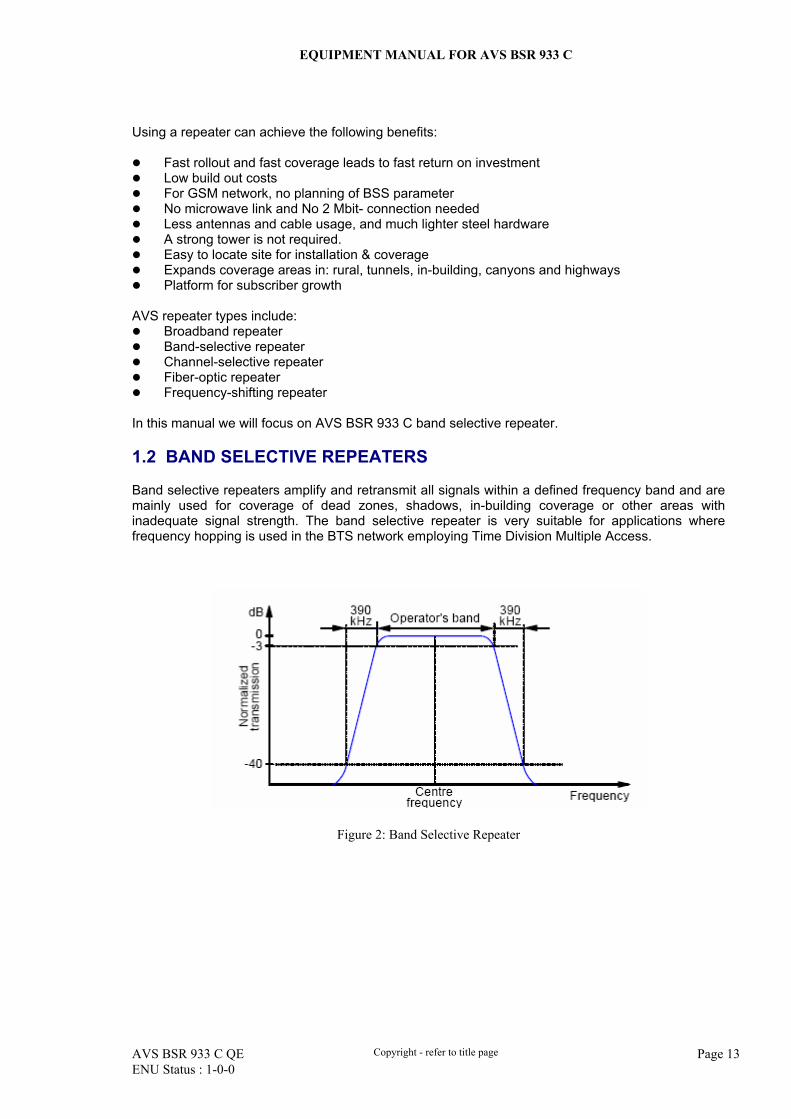
Band selective repeaters amplify and retransmit all signals within a defined frequency band and are mainly used for coverage of dead zones, shadows, in-building coverage or other areas with inadequate signal strength. The band selective repeater is very suitable for applications where frequency hopping is used in the BTS network employing Time Division Multiple Access.
Figure 2: Band Selective Repeater
EQUIPMENT MANUAL FOR AVS BSR 933 C
AVS BSR 933 C QE Copyright - refer to title page Page 14 ENU Status : 1-0-0
1.3 CHANNEL SELECTIVE REPEATERS
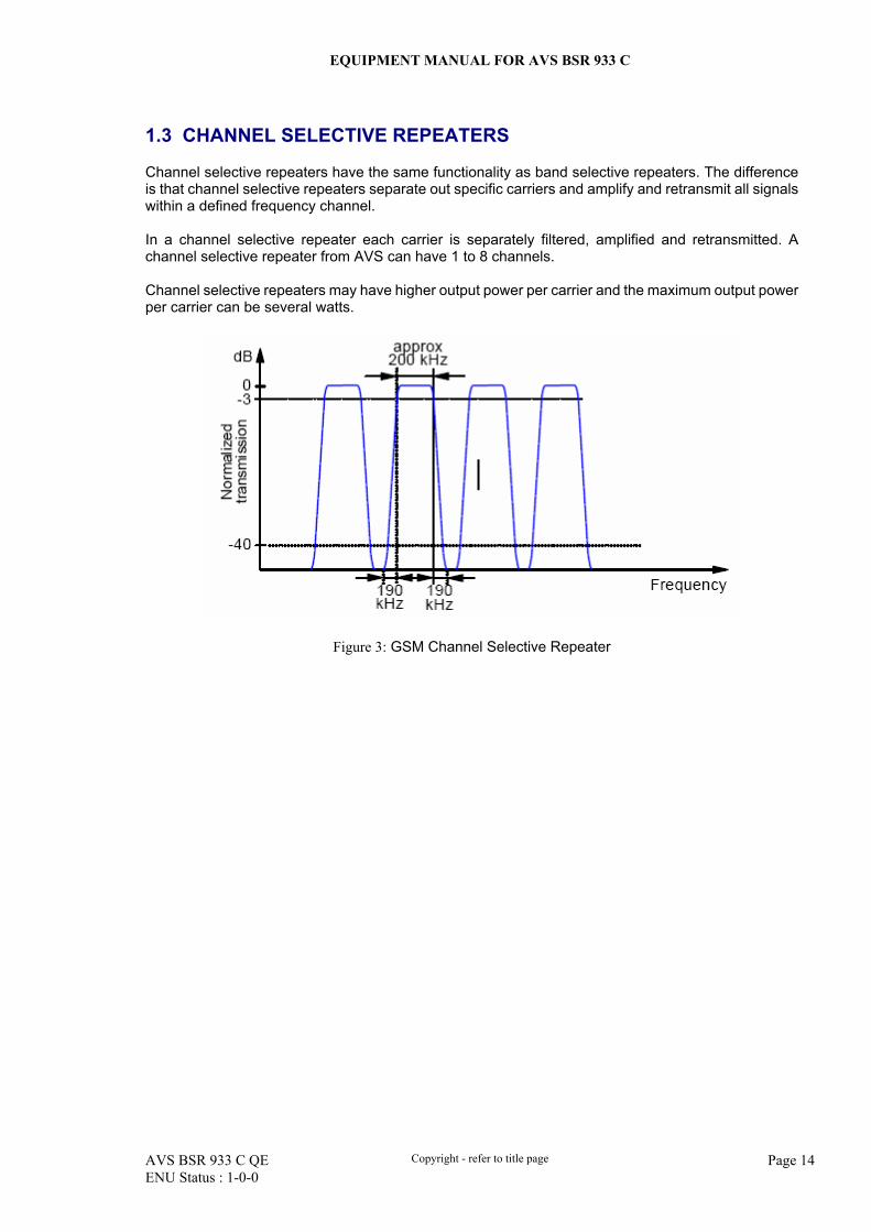
Channel selective repeaters have the same functionality as band selective repeaters. The difference is that channel selective repeaters separate out specific carriers and amplify and retransmit all signals within a defined frequency channel. In a channel selective repeater each carrier is separately filtered, amplified and retransmitted. A channel selective repeater from AVS can have 1 to 8 channels. Channel selective repeaters may have higher output power per carrier and the maximum output power per carrier can be several watts.
Figure 3: GSM Channel Selective Repeater
EQUIPMENT MANUAL FOR AVS BSR 933 C
AVS BSR 933 C QE Copyright - refer to title page Page 15 ENU Status : 1-0-0
1.4 AVS BSR 933 C REPEATER INTRODUCTION
The AVS BSR 933 C dual band selective repeater is designed for outdoor operation in the GSM900 system. A band-specific linear amplifier and filter effectively amplifies the desired BTS carriers and provides superior out-of-band rejection. Typical units incorporate up to 15MHz adjustable bandwidth with frequencies programmed to specific requirements within the whole of the GSM900 band. Dual band selectivity is implemented with two band selective filters per UL/DL. Remote configuration and surveillance is possible through AVS’s remote control and monitoring system, via laptop or wireless modem to the OMC. Li-ion backup battery built in enclosure ensures alarm signals are sent out while power is down, and optional external battery backup ensures operation in a condition with insufficient power supply or unstable supply voltages. The AVS BSR 933 C comes in a completely sealed, well-ventilated cast aluminum chassis, suitable for all weather conditions. Main features of AVS BSR 933 C:
Band selectivity from two band-selective modules with user-defined bandwidth. Output power can be easily adjusted via repeater PC software (hereinafter called RPS) software
to satisfy the requirement of network optimization. Integrated GSM radio modem for remote configuration, monitor and control. Automatic elimination for self-oscillation caused by a low isolation between DT and MT
antennas. Internal backup battery keeps the alarm unit running for up to three hours after power loss. Optional OMC is available for remote operation and maintenance of repeaters. Designed for all weather outdoor – waterproof, damp-proof and omni-sealed (IP65).
End of section
EQUIPMENT MANUAL FOR AVS BSR 933 C
AVS BSR 933 C QE Copyright - refer to title page Page 16 ENU Status : 1-0-0
2 EQUIPMENT DESCRIPTION
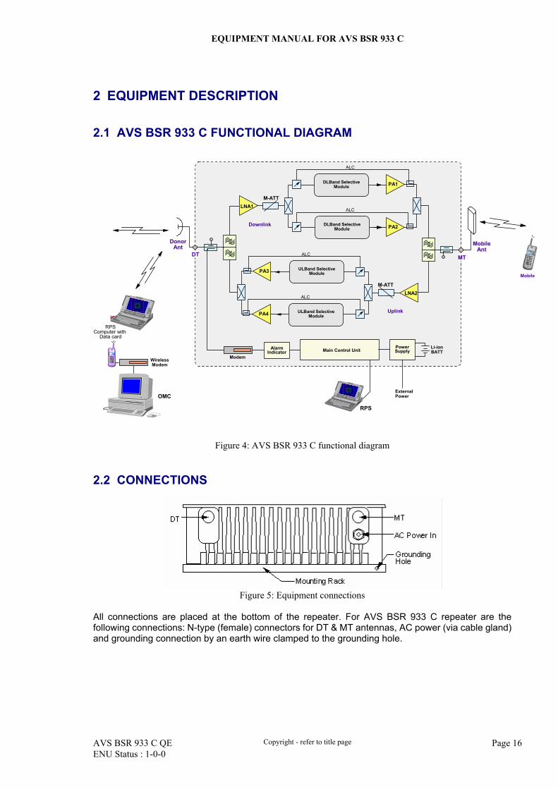
2.1 AVS BSR 933 C FUNCTIONAL DIAGRAM
M-ATTLNA1
LNA2
MobileAnt
DonorAnt
Downlink
Uplink
M-ATT
Mobile
PowerSupply
AlarmIndicator Main Control Unit
ExternalPower
RPS
Li-ionBATT
Modem
PA3
ALCDT MT
RPSComputer with
Data card
WirelessModem
OMC
ALC
PA1
ALC
PA2
PA4
ALC
DLBand SelectiveModule
DLBand SelectiveModule
ULBand SelectiveModule
ULBand SelectiveModule
Figure 4: AVS BSR 933 C functional diagram 2.2 CONNECTIONS
Figure 5: Equipment connections
All connections are placed at the bottom of the repeater. For AVS BSR 933 C repeater are the following connections: N-type (female) connectors for DT & MT antennas, AC power (via cable gland) and grounding connection by an earth wire clamped to the grounding hole.
EQUIPMENT MANUAL FOR AVS BSR 933 C
AVS BSR 933 C QE Copyright - refer to title page Page 17 ENU Status : 1-0-0
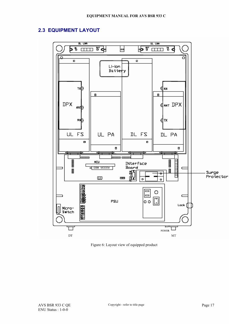
2.3 EQUIPMENT LAYOUT
Figure 6: Layout view of equipped product
EQUIPMENT MANUAL FOR AVS BSR 933 C
AVS BSR 933 C QE Copyright - refer to title page Page 18 ENU Status : 1-0-0
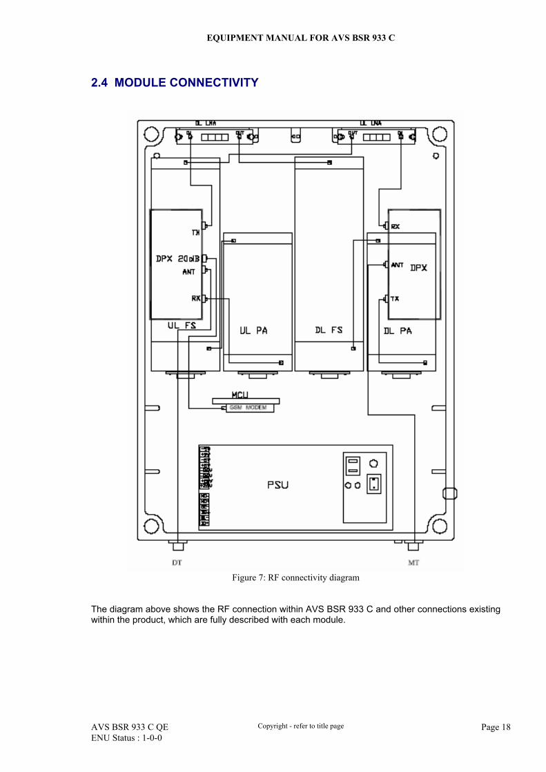
2.4 MODULE CONNECTIVITY
Figure 7: RF connectivity diagram
The diagram above shows the RF connection within AVS BSR 933 C and other connections existing within the product, which are fully described with each module.
EQUIPMENT MANUAL FOR AVS BSR 933 C
AVS BSR 933 C QE Copyright - refer to title page Page 19 ENU Status : 1-0-0
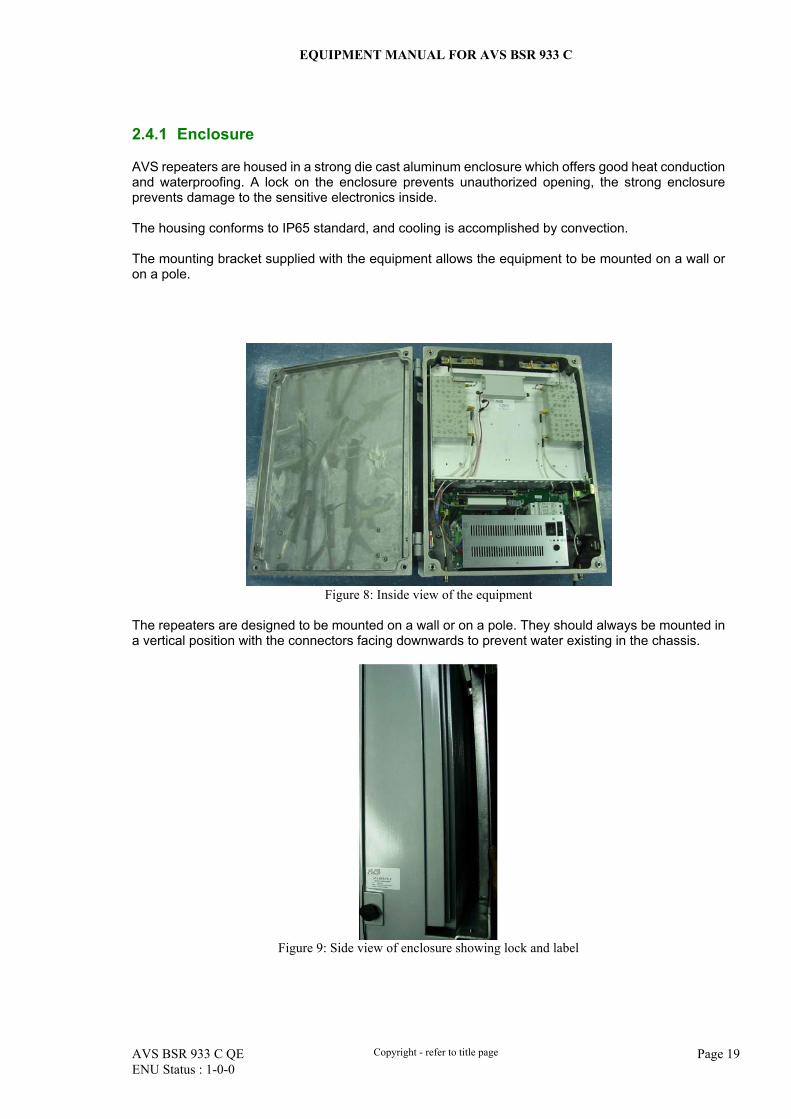
2.4.1 Enclosure
AVS repeaters are housed in a strong die cast aluminum enclosure which offers good heat conduction and waterproofing. A lock on the enclosure prevents unauthorized opening, the strong enclosure prevents damage to the sensitive electronics inside. The housing conforms to IP65 standard, and cooling is accomplished by convection. The mounting bracket supplied with the equipment allows the equipment to be mounted on a wall or on a pole.
Figure 8: Inside view of the equipment
The repeaters are designed to be mounted on a wall or on a pole. They should always be mounted in a vertical position with the connectors facing downwards to prevent water existing in the chassis.
Figure 9: Side view of enclosure showing lock and label
EQUIPMENT MANUAL FOR AVS BSR 933 C
AVS BSR 933 C QE Copyright - refer to title page Page 20 ENU Status : 1-0-0
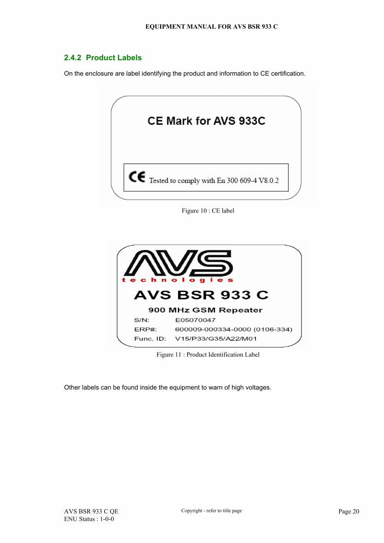
2.4.2 Product Labels
On the enclosure are label identifying the product and information to CE certification.
Figure 10 : CE label
Figure 11 : Product Identification Label
Other labels can be found inside the equipment to warn of high voltages.
EQUIPMENT MANUAL FOR AVS BSR 933 C
AVS BSR 933 C QE Copyright - refer to title page Page 21 ENU Status : 1-0-0
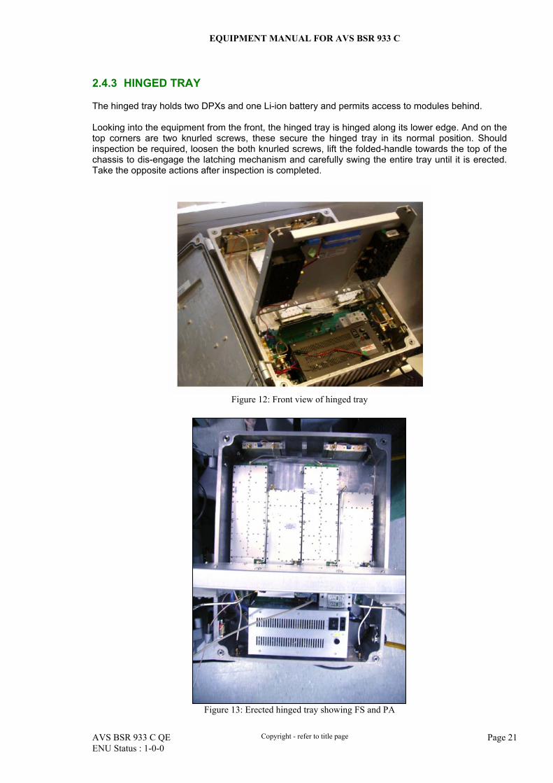
2.4.3 HINGED TRAY
The hinged tray holds two DPXs and one Li-ion battery and permits access to modules behind. Looking into the equipment from the front, the hinged tray is hinged along its lower edge. And on the top corners are two knurled screws, these secure the hinged tray in its normal position. Should inspection be required, loosen the both knurled screws, lift the folded-handle towards the top of the chassis to dis-engage the latching mechanism and carefully swing the entire tray until it is erected. Take the opposite actions after inspection is completed.
Figure 12: Front view of hinged tray
Figure 13: Erected hinged tray showing FS and PA
EQUIPMENT MANUAL FOR AVS BSR 933 C
AVS BSR 933 C QE Copyright - refer to title page Page 22 ENU Status : 1-0-0
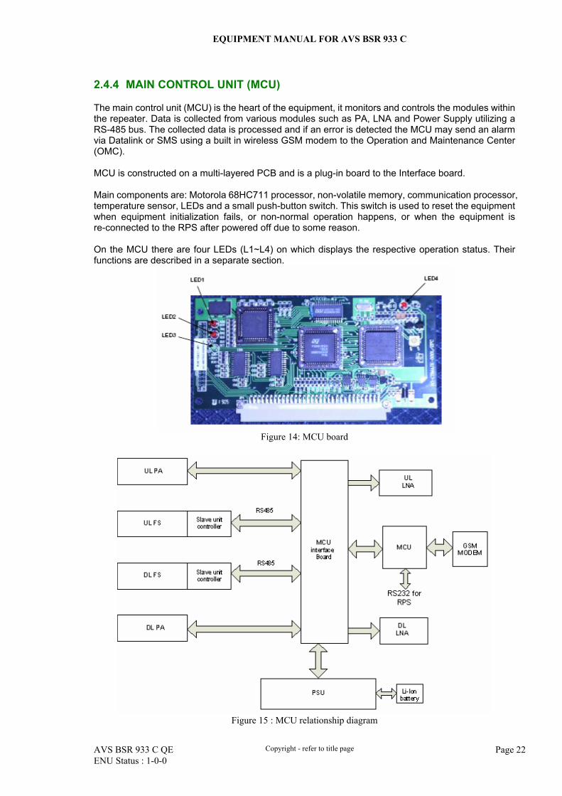
2.4.4 MAIN CONTROL UNIT (MCU)
The main control unit (MCU) is the heart of the equipment, it monitors and controls the modules within the repeater. Data is collected from various modules such as PA, LNA and Power Supply utilizing a RS-485 bus. The collected data is processed and if an error is detected the MCU may send an alarm via Datalink or SMS using a built in wireless GSM modem to the Operation and Maintenance Center (OMC). MCU is constructed on a multi-layered PCB and is a plug-in board to the Interface board. Main components are: Motorola 68HC711 processor, non-volatile memory, communication processor, temperature sensor, LEDs and a small push-button switch. This switch is used to reset the equipment when equipment initialization fails, or non-normal operation happens, or when the equipment is re-connected to the RPS after powered off due to some reason. On the MCU there are four LEDs (L1~L4) on which displays the respective operation status. Their functions are described in a separate section.
Figure 14: MCU board
Figure 15 : MCU relationship diagram
EQUIPMENT MANUAL FOR AVS BSR 933 C
AVS BSR 933 C QE Copyright - refer to title page Page 23 ENU Status : 1-0-0
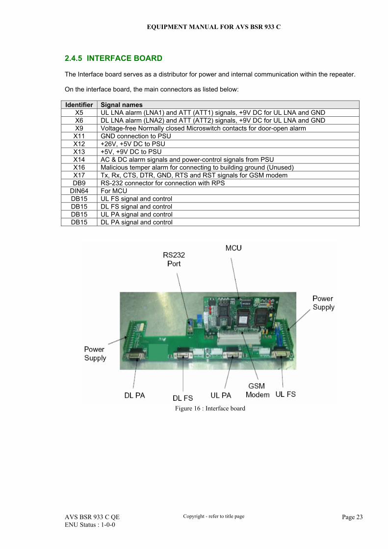
2.4.5 INTERFACE BOARD
The Interface board serves as a distributor for power and internal communication within the repeater. On the interface board, the main connectors as listed below: Identifier Signal names
X5 UL LNA alarm (LNA1) and ATT (ATT1) signals, +9V DC for UL LNA and GND X6 DL LNA alarm (LNA2) and ATT (ATT2) signals, +9V DC for UL LNA and GND X9 Voltage-free Normally closed Microswitch contacts for door-open alarm
X11 GND connection to PSU X12 +26V, +5V DC to PSU X13 +5V, +9V DC to PSU X14 AC & DC alarm signals and power-control signals from PSU X16 Malicious temper alarm for connecting to building ground (Unused) X17 Tx, Rx, CTS, DTR, GND, RTS and RST signals for GSM modem DB9 RS-232 connector for connection with RPS
DIN64 For MCU DB15 UL FS signal and control DB15 DL FS signal and control DB15 UL PA signal and control DB15 DL PA signal and control
Figure 16 : Interface board
EQUIPMENT MANUAL FOR AVS BSR 933 C
AVS BSR 933 C QE Copyright - refer to title page Page 24 ENU Status : 1-0-0
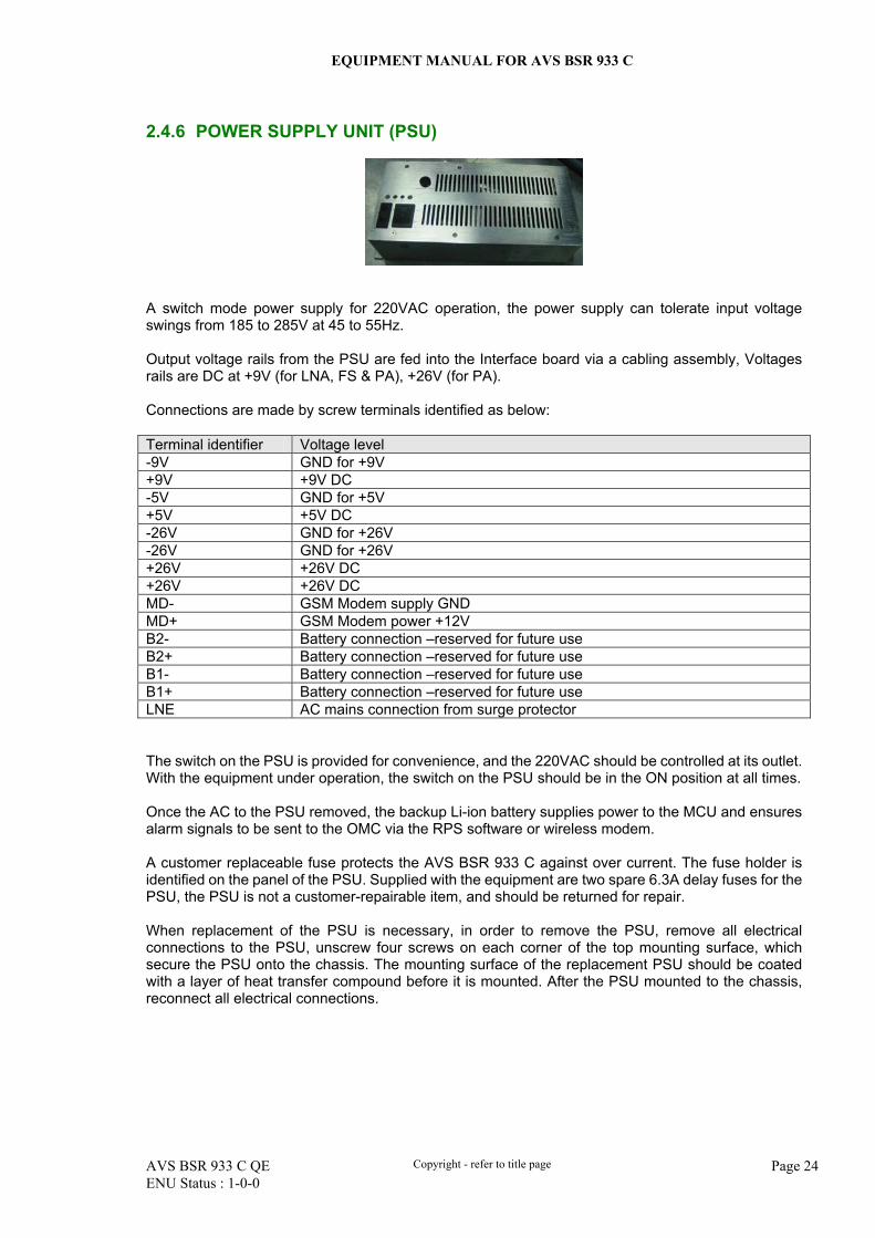
2.4.6 POWER SUPPLY UNIT (PSU)
A switch mode power supply for 220VAC operation, the power supply can tolerate input voltage swings from 185 to 285V at 45 to 55Hz. Output voltage rails from the PSU are fed into the Interface board via a cabling assembly, Voltages rails are DC at +9V (for LNA, FS & PA), +26V (for PA). Connections are made by screw terminals identified as below: Terminal identifier Voltage level -9V GND for +9V +9V +9V DC -5V GND for +5V +5V +5V DC -26V GND for +26V -26V GND for +26V +26V +26V DC +26V +26V DC MD- GSM Modem supply GND MD+ GSM Modem power +12V B2- Battery connection –reserved for future use B2+ Battery connection –reserved for future use B1- Battery connection –reserved for future use B1+ Battery connection –reserved for future use LNE AC mains connection from surge protector The switch on the PSU is provided for convenience, and the 220VAC should be controlled at its outlet. With the equipment under operation, the switch on the PSU should be in the ON position at all times. Once the AC to the PSU removed, the backup Li-ion battery supplies power to the MCU and ensures alarm signals to be sent to the OMC via the RPS software or wireless modem. A customer replaceable fuse protects the AVS BSR 933 C against over current. The fuse holder is identified on the panel of the PSU. Supplied with the equipment are two spare 6.3A delay fuses for the PSU, the PSU is not a customer-repairable item, and should be returned for repair. When replacement of the PSU is necessary, in order to remove the PSU, remove all electrical connections to the PSU, unscrew four screws on each corner of the top mounting surface, which secure the PSU onto the chassis. The mounting surface of the replacement PSU should be coated with a layer of heat transfer compound before it is mounted. After the PSU mounted to the chassis, reconnect all electrical connections.
EQUIPMENT MANUAL FOR AVS BSR 933 C
AVS BSR 933 C QE Copyright - refer to title page Page 25 ENU Status : 1-0-0
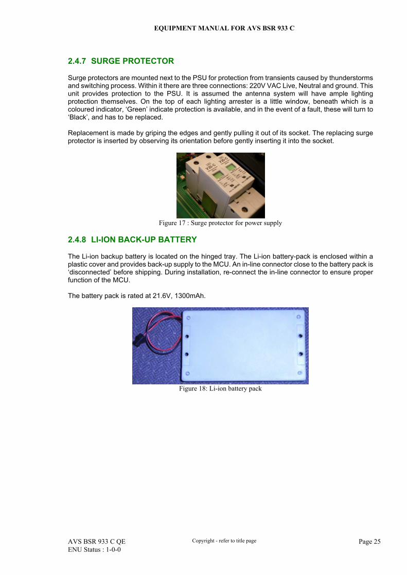
2.4.7 SURGE PROTECTOR
Surge protectors are mounted next to the PSU for protection from transients caused by thunderstorms and switching process. Within it there are three connections: 220V VAC Live, Neutral and ground. This unit provides protection to the PSU. It is assumed the antenna system will have ample lighting protection themselves. On the top of each lighting arrester is a little window, beneath which is a coloured indicator, ‘Green’ indicate protection is available, and in the event of a fault, these will turn to ‘Black’, and has to be replaced. Replacement is made by griping the edges and gently pulling it out of its socket. The replacing surge protector is inserted by observing its orientation before gently inserting it into the socket.
Figure 17 : Surge protector for power supply
2.4.8 LI-ION BACK-UP BATTERY
The Li-ion backup battery is located on the hinged tray. The Li-ion battery-pack is enclosed within a plastic cover and provides back-up supply to the MCU. An in-line connector close to the battery pack is ‘disconnected’ before shipping. During installation, re-connect the in-line connector to ensure proper function of the MCU. The battery pack is rated at 21.6V, 1300mAh.
Figure 18: Li-ion battery pack
EQUIPMENT MANUAL FOR AVS BSR 933 C
AVS BSR 933 C QE Copyright - refer to title page Page 26 ENU Status : 1-0-0
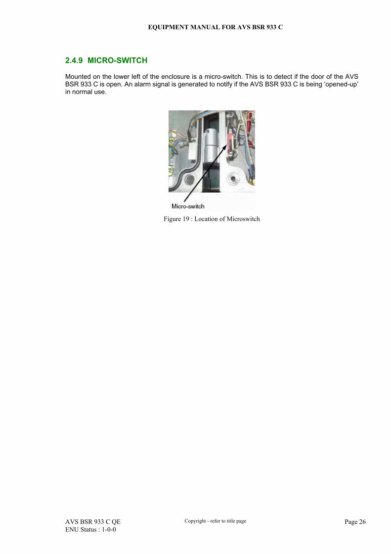
2.4.9 MICRO-SWITCH
Mounted on the lower left of the enclosure is a micro-switch. This is to detect if the door of the AVS BSR 933 C is open. An alarm signal is generated to notify if the AVS BSR 933 C is being ‘opened-up’ in normal use.
Figure 19 : Location of Microswitch
EQUIPMENT MANUAL FOR AVS BSR 933 C
AVS BSR 933 C QE Copyright - refer to title page Page 27 ENU Status : 1-0-0
2.4.10 DUPLEXER (DPX)
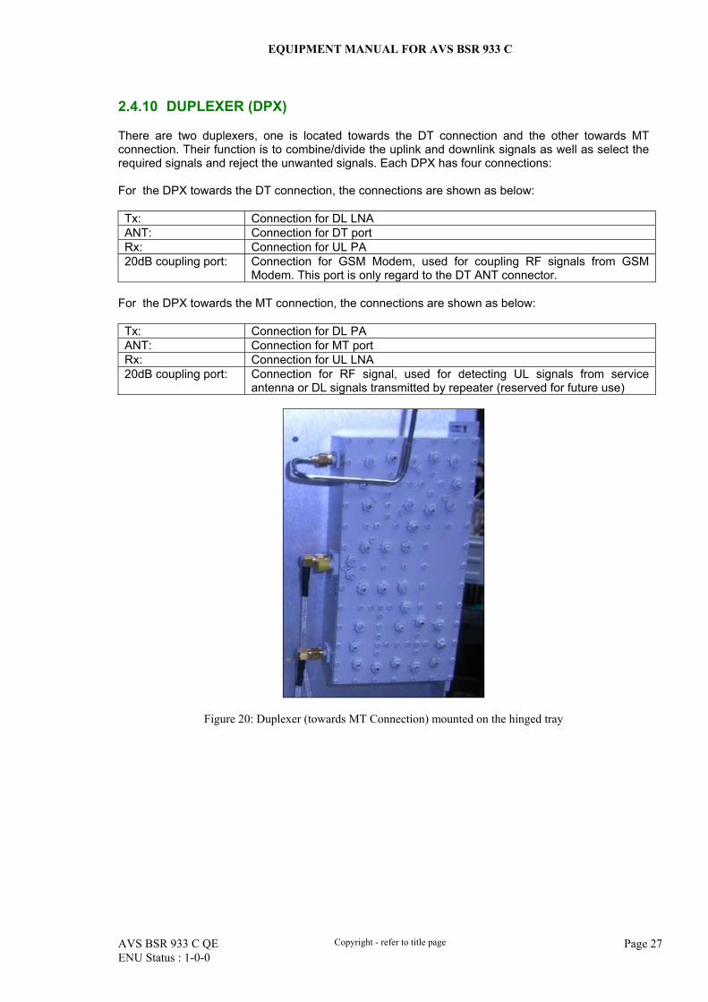
There are two duplexers, one is located towards the DT connection and the other towards MT connection. Their function is to combine/divide the uplink and downlink signals as well as select the required signals and reject the unwanted signals. Each DPX has four connections: For the DPX towards the DT connection, the connections are shown as below: Tx: Connection for DL LNA ANT: Connection for DT port Rx: Connection for UL PA 20dB coupling port: Connection for GSM Modem, used for coupling RF signals from GSM
Modem. This port is only regard to the DT ANT connector. For the DPX towards the MT connection, the connections are shown as below: Tx: Connection for DL PA ANT: Connection for MT port Rx: Connection for UL LNA 20dB coupling port: Connection for RF signal, used for detecting UL signals from service
antenna or DL signals transmitted by repeater (reserved for future use)
Figure 20: Duplexer (towards MT Connection) mounted on the hinged tray
EQUIPMENT MANUAL FOR AVS BSR 933 C
AVS BSR 933 C QE Copyright - refer to title page Page 28 ENU Status : 1-0-0
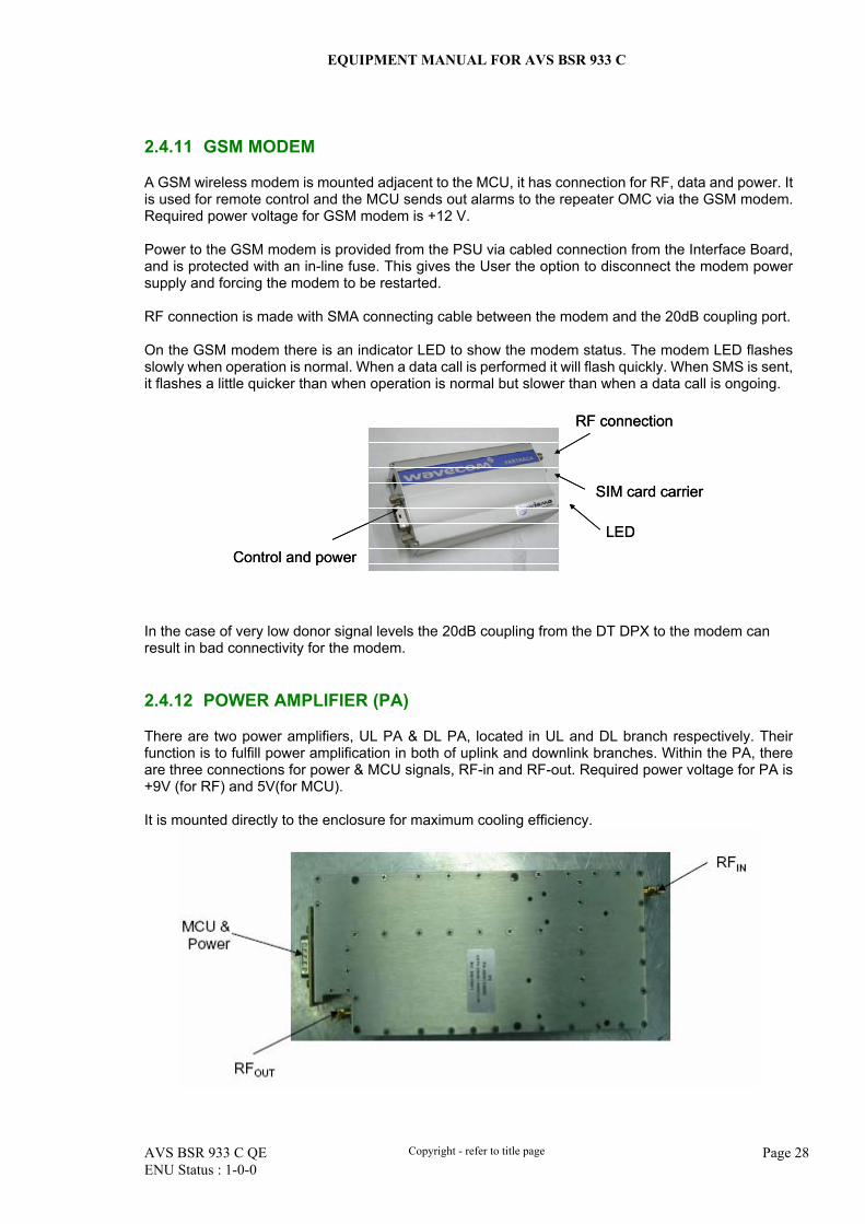
2.4.11 GSM MODEM
A GSM wireless modem is mounted adjacent to the MCU, it has connection for RF, data and power. It is used for remote control and the MCU sends out alarms to the repeater OMC via the GSM modem. Required power voltage for GSM modem is +12 V. Power to the GSM modem is provided from the PSU via cabled connection from the Interface Board, and is protected with an in-line fuse. This gives the User the option to disconnect the modem power supply and forcing the modem to be restarted. RF connection is made with SMA connecting cable between the modem and the 20dB coupling port. On the GSM modem there is an indicator LED to show the modem status. The modem LED flashes slowly when operation is normal. When a data call is performed it will flash quickly. When SMS is sent, it flashes a little quicker than when operation is normal but slower than when a data call is ongoing.
Control and power
RF connection
SIM card carrier
LED
Control and power
RF connection
SIM card carrier
LED
In the case of very low donor signal levels the 20dB coupling from the DT DPX to the modem can result in bad connectivity for the modem. 2.4.12 POWER AMPLIFIER (PA)
There are two power amplifiers, UL PA & DL PA, located in UL and DL branch respectively. Their function is to fulfill power amplification in both of uplink and downlink branches. Within the PA, there are three connections for power & MCU signals, RF-in and RF-out. Required power voltage for PA is +9V (for RF) and 5V(for MCU). It is mounted directly to the enclosure for maximum cooling efficiency.
EQUIPMENT MANUAL FOR AVS BSR 933 C
AVS BSR 933 C QE Copyright - refer to title page Page 29 ENU Status : 1-0-0
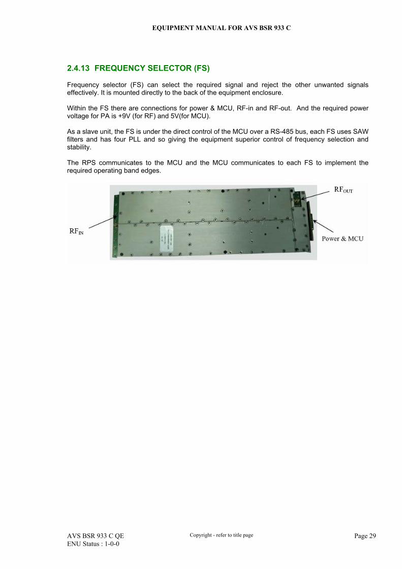
2.4.13 FREQUENCY SELECTOR (FS)
Frequency selector (FS) can select the required signal and reject the other unwanted signals effectively. It is mounted directly to the back of the equipment enclosure. Within the FS there are connections for power & MCU, RF-in and RF-out. And the required power voltage for PA is +9V (for RF) and 5V(for MCU). As a slave unit, the FS is under the direct control of the MCU over a RS-485 bus, each FS uses SAW filters and has four PLL and so giving the equipment superior control of frequency selection and stability. The RPS communicates to the MCU and the MCU communicates to each FS to implement the required operating band edges.
EQUIPMENT MANUAL FOR AVS BSR 933 C
AVS BSR 933 C QE Copyright - refer to title page Page 30 ENU Status : 1-0-0
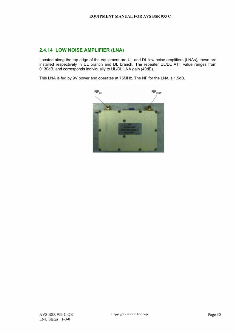
2.4.14 LOW NOISE AMPLIFIER (LNA)
Located along the top edge of the equipment are UL and DL low noise amplifiers (LNAs), these are installed respectively in UL branch and DL branch. The repeater UL/DL ATT value ranges from 0~30dB, and corresponds individually to UL/DL LNA gain (40dB). This LNA is fed by 9V power and operates at 75MHz. The NF for the LNA is 1.5dB.
EQUIPMENT MANUAL FOR AVS BSR 933 C
AVS BSR 933 C QE Copyright - refer to title page Page 31 ENU Status : 1-0-0
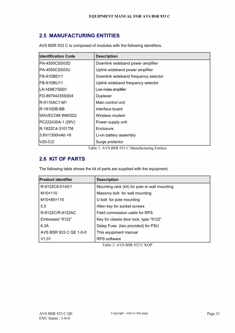
2.5 MANUFACTURING ENTITIES
AVS BSR 933 C is composed of modules with the following identifiers. Identification Code Description
PA-4550CSS03D Downlink wideband power amplifier PA-4550CSS03U Uplink wideband power amplifier FB-91DBD11 Downlink wideband frequency selector FB-91DBU11 Uplink wideband frequency selector LA-1439C1SS01 Low noise amplifier FD-89794235SS04 Duplexer R-9110AC1-M1 Main control unit R-1810DB-BB Interface board WAVECOM WMOD2 Wireless modem PC222435A-1 (26V) Power supply unit R-1822C4-3101TM Enclosure 3.6V/1300mAh ×6 Li-on battery assembly
V20-C/2 Surge protector Table 1: AVS BSR 933 C Manufacturing Entities
2.6 KIT OF PARTS
The following table shows the kit of parts are supplied with the equipment. Product identifier Description
R-9122C8-5140/1 Mounting rack (kit) for pole or wall mounting M10×110 Masonry bolt for wall mounting M10×85×110 U bolt for pole mounting 5.5 Allen key for socket screws R-9122C/R-9122AC Field commission cable for RPS Embossed “9122” Key for classis door lock, type “9122” 6.3A Delay Fuse (two provided) for PSU AVS BSR 933 C QE 1-0-0 This equipment manual V1.01 RPS software
Table 2: AVS BSR 933 C KOP
EQUIPMENT MANUAL FOR AVS BSR 933 C
AVS BSR 933 C QE Copyright - refer to title page Page 32 ENU Status : 1-0-0
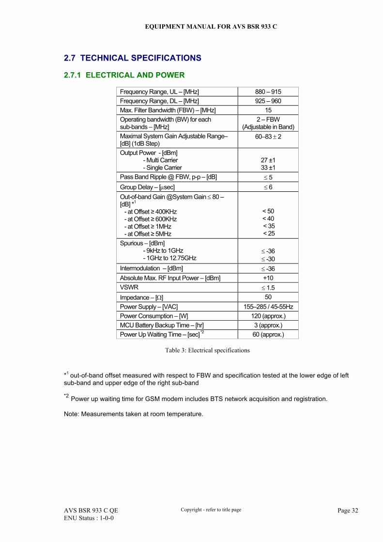
2.7 TECHNICAL SPECIFICATIONS
2.7.1 ELECTRICAL AND POWER
Frequency Range, UL – [MHz] 880 – 915 Frequency Range, DL – [MHz] 925 – 960 Max. Filter Bandwidth (FBW) – [MHz] 15 Operating bandwidth (BW) for each sub-bands – [MHz]
2 – FBW (Adjustable in Band)
Maximal System Gain Adjustable Range– [dB] (1dB Step)
60–83 ± 2
Output Power - [dBm] - Multi Carrier - Single Carrier
27 ±1 33 ±1
Pass Band Ripple @ FBW, p-p – [dB] ≤ 5 Group Delay – [µsec] ≤ 6 Out-of-band Gain @System Gain ≤ 80 – [dB] *1 - at Offset ≥ 400KHz - at Offset ≥ 600KHz - at Offset ≥ 1MHz - at Offset ≥ 5MHz
< 50 < 40 < 35 < 25
Spurious – [dBm] - 9kHz to 1GHz - 1GHz to 12.75GHz
≤ -36 ≤ -30
Intermodulation – [dBm] ≤ -36 Absolute Max. RF Input Power – [dBm] +10 VSWR ≤ 1.5 Impedance – [Ω] 50 Power Supply – [VAC] 155–285 / 45-55Hz Power Consumption – [W] 120 (approx.) MCU Battery Backup Time – [hr] 3 (approx.) Power Up Waiting Time – [sec] *2 60 (approx.)
Table 3: Electrical specifications
*1 out-of-band offset measured with respect to FBW and specification tested at the lower edge of left sub-band and upper edge of the right sub-band *2 Power up waiting time for GSM modem includes BTS network acquisition and registration. Note: Measurements taken at room temperature.
EQUIPMENT MANUAL FOR AVS BSR 933 C
AVS BSR 933 C QE Copyright - refer to title page Page 33 ENU Status : 1-0-0
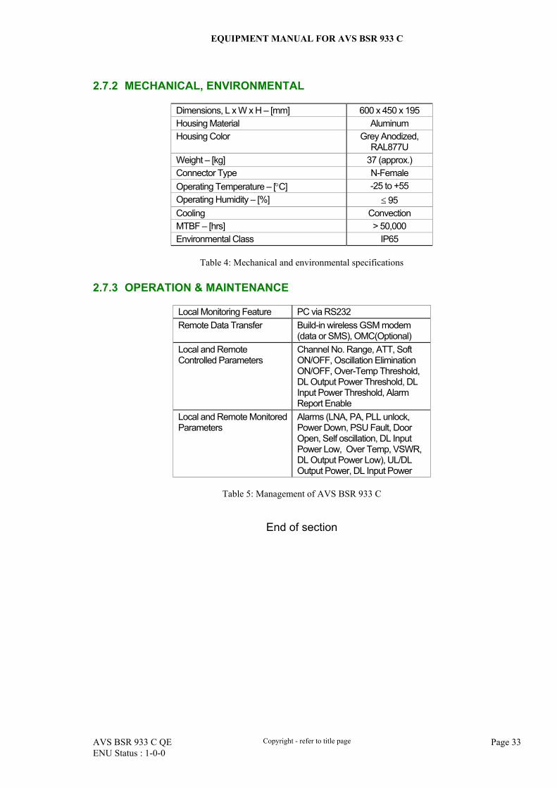
2.7.2 MECHANICAL, ENVIRONMENTAL
Dimensions, L x W x H – [mm] 600 x 450 x 195 Housing Material Aluminum Housing Color Grey Anodized,
RAL877U Weight – [kg] 37 (approx.) Connector Type N-Female Operating Temperature – [°C] -25 to +55 Operating Humidity – [%] ≤ 95 Cooling Convection MTBF – [hrs] > 50,000 Environmental Class IP65
Table 4: Mechanical and environmental specifications
2.7.3 OPERATION & MAINTENANCE
Local Monitoring Feature PC via RS232 Remote Data Transfer Build-in wireless GSM modem
(data or SMS), OMC(Optional) Local and Remote Controlled Parameters
Channel No. Range, ATT, Soft ON/OFF, Oscillation Elimination ON/OFF, Over-Temp Threshold, DL Output Power Threshold, DL Input Power Threshold, Alarm Report Enable
Local and Remote Monitored Parameters
Alarms (LNA, PA, PLL unlock, Power Down, PSU Fault, Door Open, Self oscillation, DL Input Power Low, Over Temp, VSWR, DL Output Power Low), UL/DL Output Power, DL Input Power
Table 5: Management of AVS BSR 933 C
End of section
EQUIPMENT MANUAL FOR AVS BSR 933 C
AVS BSR 933 C QE Copyright - refer to title page Page 34 ENU Status : 1-0-0
3 INSTALLATION
3.1 WARNINGS AND ALERTS
Radio Frequency energies There may be situations, particularly the workplace environments adjacent to high-powered RF sources, where recommended limits for safe exposure of human beings to RF energy could be exceeded. In such cases, restrictive measures or actions may be necessary to ensure the safe use of RF energy. Assume that other RF energies exist in the vicinity, always maintain a minimum distance of 1m from the human beings (assumption 935 MHz at 40W emitted power, source IEEE) High voltage The equipment has been designed and constructed as to prevent as far as reasonably practicable danger. Any activity, such as installation, operation and maintenance, on or near the equipment must be as far as reasonably free from danger. Where there is a risk of damage to electrical systems due to adverse weather, extreme temperatures, wet, corrosive or dirty conditions, flammable or explosive atmosphere, then the system must be suitably installed to avoid such a danger. To reduce the risk of damage to the equipment and to the customer, shut down the equipment and take action to isolate mains supply when performing any intrusive actions. Protective Earthing Equipment must be well grounded for the purpose of protecting individuals from electrical risk. Handling Precautions Precautions should be taken in equipment handling activities including lifting, lowering, pushing, pulling, carrying, moving or holding, or the activities to prevent an object, animal or other aspects going into the chassis, or the activities when extra efforts are needed such as pulling a lever, or operating power tools. ESD Take necessary precautions when handling ESD-sensitive devices. Assume that all solid-state electronic devices are ESD-sensitive. Do use a grounded wriststrap or the like while working with ESD-sensitive devices. Transport, store, and handle ESD-sensitive devices in static-free environments.
EQUIPMENT MANUAL FOR AVS BSR 933 C
AVS BSR 933 C QE Copyright - refer to title page Page 35 ENU Status : 1-0-0
3.2 SITE PLANNING CONSIDERATIONS
Site considerations The repeater is designed to be waterproof, rainproof, and with snow protection. Temporary protection should be taken when the equipment chassis is opened for installation or maintenance in an outdoor environment. The equipment must not be opened for installation or maintenance in bad weather (e.g. gale, storm rainfall, extreme temperatures and high humidity) Installation location Mounting surface shall be suitable to support weight of the equipment: for AVS BSR 933 C, this is about 37 kg (82 lb.). Environmental Humidity has an effect on the reliability of the equipment. It is recommended to install the equipment in location having stable temperature and un-restricted air-flow. AVS BSR 933 C equipment has been designed to operate in the ambient air temperature range of -25C to +55C (-13F to 131F) at ≤ 95% relative humidity. Should the direct day light temperature exceeds +55C (131F), then barrier device should be installed in to protect the equipment to limit sunlight exposure. Powering The power supply unit (PSU) provides power to all modules within the chassis. The PSU accepts 155~285VAC/50Hz±5Hz. It is recommended that the PSU operate on a dedicated AC circuit breaker or fused circuit. In order to avoid electromagnetic interference, select the AVS BSR 933 C mounting location to minimize interference from electromagnetic sources such as high powered equipment. Grounding requirement Verify the equipment has been well grounded, this includes antennas and all cables connected. Ensure lightning protection for the antennas is properly grounded. Cable routing Four cables entries to the equipment: Two co-axial (connection for MT and DT), one 220VAC mains-power cable and 1x RS-232 commission cable during commissioning with the door open. Manual handling During transportation and installation, take necessary handling precautions to avoid potential physical injury to the installation personnel or damages to the equipment. (Reference 0.6.2)
EQUIPMENT MANUAL FOR AVS BSR 933 C
AVS BSR 933 C QE Copyright - refer to title page Page 36 ENU Status : 1-0-0
PA1
PA2
MobileBTS
40dBm
?dBm
-90dBm
GD=?
Gu=?Loss=120dB
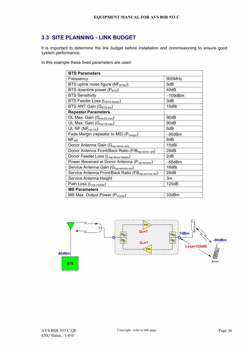
3.3 SITE PLANNING - LINK BUDGET
It is important to determine the link budget before installation and commissioning to ensure good system performance. In this example these fixed parameters are used:
BTS Parameters Frequency 900MHz BTS uplink noise figure (NFBTSU): 5dB BTS downlink power (PBTS): 40dB BTS Sensitivity −109dBm BTS Feeder Loss (LBTS-feeder) 3dB BTS ANT Gain (GBTS-ant) 15dBi Repeater Parameters DL Max. Gain (Grep-DLmax) 90dB UL Max. Gain (Grep-ULmax) 90dB UL NF (NFrep-UL) 6dB Fade Margin (repeater to MS) (Pmargin) −90dBm NFMS 6dB Donor Antenna Gain (Grep-donor ant) 15dBi Donor Antenna Front/Back Ratio (F/Brep-donor ant) 28dB Donor Feeder Loss (Lrep-donor feeder) 2dB Power Received at Donor Antenna (Prep-receive) −65dBm Service Antenna Gain (Grep-service ant) 18dBi Service Antenna Front/Back Ratio (FBrep-service ant) 28dB Service Antenna Height 3m Path Loss (Lrep-mobile) 120dB MS Parameters MS Max. Output Power (Pmobile) 33dBm
EQUIPMENT MANUAL FOR AVS BSR 933 C
AVS BSR 933 C QE Copyright - refer to title page Page 37 ENU Status : 1-0-0
Downlink Path: Fade margin of the coverage area (Pmargin) should satisfy the following:
Rrep-receive + Grep-donor ant −Lrep-donor feeder +Grep-DL −Lrep-mobile =Pmargin −65dBm + 15dBi − 2dB + Grep-DL − 120dB = −90dBm
From above, we derived: Grep-DL = −90dBm + 120dB−(−65dBm) − 15dBi + 2dB =82dB
Thus the downlink master ATT should be: Grep-DLmax −Grep-DL =90−82 =8dB
Note: Grep-DL is the actual downlink Gain after the repeater is installed. Uplink Path: The received power at BTS receiver (PBTS-receive) should satisfy the following formula: PBTS-receive =Pmobile +Grep-UL −Lrep-donor feeder +Grep-donor ant −(PBTS −LBTS-feeder +GBTS-ant −Prep-receive) ≥RBTS
33 −120 +Grep-UL −2 +15 −[40 −3 +15 − (−65)] ≥109
Therefore Grep-UL id determined as 82dB Thus the uplink master ATT should be:
Grep-ULmax −Grep-UL =90 −82 = 8dB
Note: Grep-UL is the actual uplink Gain after the repeater installed.
NFTotal=NFBTS+10LOG(1+10(NFrep-UL−NFBTS+Grep-UL- LBTS-REP)/10)= 5dB +1.19dB = 6.19dB Assuming that repeater noise power at MT port equals to −120dBm, then: Repeater noise power at BTS receiver should be:
NFBTS = −120dBm + 82dB −105dB +6.19dB = −136.81dBm The total BTS thermal noise should be:
−121dBm + (−136.81dBm) = −120.8dBm From the results we can see the BTS thermal noise has increased by only 0.2dBm after the insertion of a repeater.
EQUIPMENT MANUAL FOR AVS BSR 933 C
AVS BSR 933 C QE Copyright - refer to title page Page 38 ENU Status : 1-0-0
Isolation: In the repeater application, isolation between donor antenna and service antenna should be taken into consideration and satisfy the following:
I ≥ Grep-DL +15dB =97dB Assuming that both donor antenna and service antenna are horizontally installed, then:
I = 32.4+20logf+20logD −(Grep-donor ant +Grep-service ant) +(FBrep-donor ant +FBrep-service ant) I =32.4 +20log(900) +20logD −(12dBi +18dBi) +(28dB +28dB) ≥97dB
From above, we derived D ≥133m Assuming that both donor antenna and service antenna are vertically installed, then:
I =28 +40log(H/λ) − (Grep-donor ant +Grep-service ant) +( FBrep-donor ant +FBrep-service ant) ≥97dB From above, we derived H ≥4.7m
EQUIPMENT MANUAL FOR AVS BSR 933 C
AVS BSR 933 C QE Copyright - refer to title page Page 39 ENU Status : 1-0-0
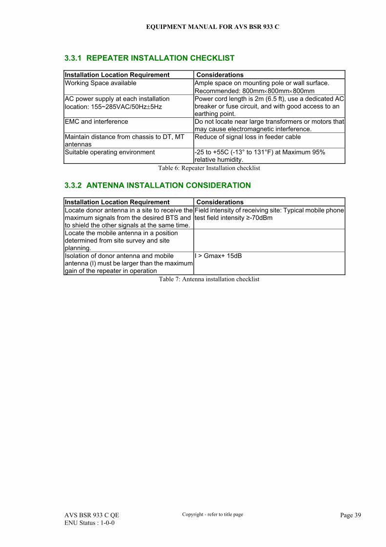
3.3.1 REPEATER INSTALLATION CHECKLIST
Installation Location Requirement Considerations Working Space available Ample space on mounting pole or wall surface.
Recommended: 800mm×800mm×800mm AC power supply at each installation location: 155~285VAC/50Hz±5Hz
Power cord length is 2m (6.5 ft), use a dedicated AC breaker or fuse circuit, and with good access to an earthing point.
EMC and interference Do not locate near large transformers or motors that may cause electromagnetic interference.
Maintain distance from chassis to DT, MT antennas
Reduce of signal loss in feeder cable
Suitable operating environment -25 to +55C (-13° to 131°F) at Maximum 95% relative humidity.
Table 6: Repeater Installation checklist 3.3.2 ANTENNA INSTALLATION CONSIDERATION
Installation Location Requirement Considerations Locate donor antenna in a site to receive the maximum signals from the desired BTS and to shield the other signals at the same time.
Field intensity of receiving site: Typical mobile phone test field intensity ≥-70dBm
Locate the mobile antenna in a position determined from site survey and site planning.
Isolation of donor antenna and mobile antenna (I) must be larger than the maximum gain of the repeater in operation
I > Gmax+ 15dB
Table 7: Antenna installation checklist
EQUIPMENT MANUAL FOR AVS BSR 933 C
AVS BSR 933 C QE Copyright - refer to title page Page 40 ENU Status : 1-0-0
3.4 INSTALLATION PROCEDURES
3.4.1 GOODS INWARDS INSPECTION
Verify the number of packages received against the packing list. Check all packages for external damage; report any external damage to the shipping carrier. If
there is damage, a shipping agent should be present before unpacking and inspecting the contents because damage caused during transit is the responsibility of the agent.
Open and check each package against the packing list. If any items are missing, contact AVS. Do not remove items from antistatic packing until installation. If damage is discovered at the time
of installation, contact the shipping agent. 3.4.2 TOOLS
See appendix A for a full list of tools required for new installation and routine maintenance. 3.4.3 PREPARATION
Repeater: Mounting surface or pole capable of support chassis’ weight: < 37 kg (82 lb.) Power outlet within 2m / 6.5 ft. Terminate unused antenna ports with a 50 ohm terminator. Earthing point/Safety ground within 2m / 6.5 ft.
Antenna:
Antenna installation is covered by their respective manuals. Take normal precautions when preparing and handling feeder cables to ensure they are not damaged.
EQUIPMENT MANUAL FOR AVS BSR 933 C
AVS BSR 933 C QE Copyright - refer to title page Page 41 ENU Status : 1-0-0
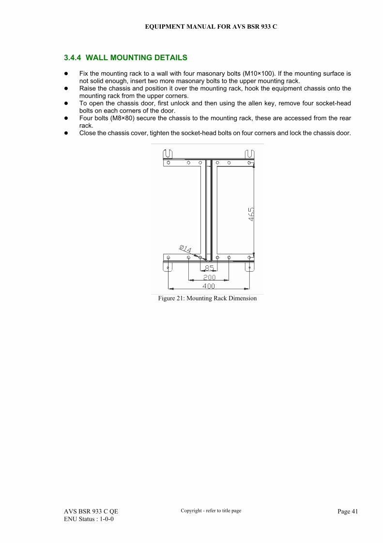
3.4.4 WALL MOUNTING DETAILS
Fix the mounting rack to a wall with four masonary bolts (M10×100). If the mounting surface is not solid enough, insert two more masonary bolts to the upper mounting rack.
Raise the chassis and position it over the mounting rack, hook the equipment chassis onto the mounting rack from the upper corners.
To open the chassis door, first unlock and then using the allen key, remove four socket-head bolts on each corners of the door.
Four bolts (M8×80) secure the chassis to the mounting rack, these are accessed from the rear rack.
Close the chassis cover, tighten the socket-head bolts on four corners and lock the chassis door.
Figure 21: Mounting Rack Dimension
EQUIPMENT MANUAL FOR AVS BSR 933 C
AVS BSR 933 C QE Copyright - refer to title page Page 42 ENU Status : 1-0-0
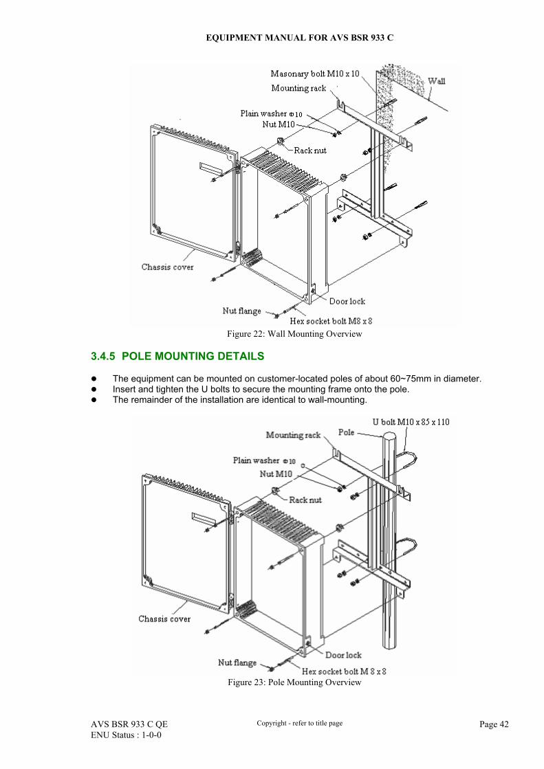
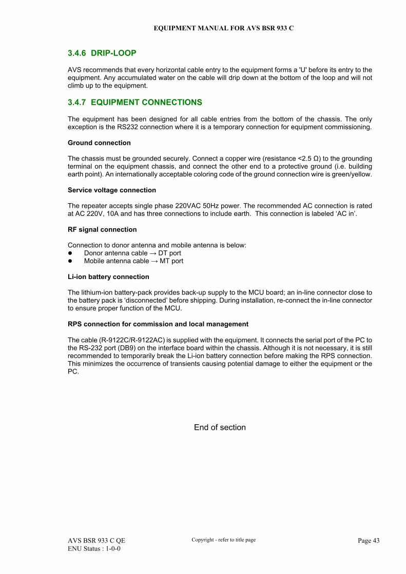
Figure 22: Wall Mounting Overview
3.4.5 POLE MOUNTING DETAILS
The equipment can be mounted on customer-located poles of about 60~75mm in diameter. Insert and tighten the U bolts to secure the mounting frame onto the pole. The remainder of the installation are identical to wall-mounting.
Figure 23: Pole Mounting Overview
EQUIPMENT MANUAL FOR AVS BSR 933 C
AVS BSR 933 C QE Copyright - refer to title page Page 43 ENU Status : 1-0-0
3.4.6 DRIP-LOOP
AVS recommends that every horizontal cable entry to the equipment forms a 'U' before its entry to the equipment. Any accumulated water on the cable will drip down at the bottom of the loop and will not climb up to the equipment. 3.4.7 EQUIPMENT CONNECTIONS
The equipment has been designed for all cable entries from the bottom of the chassis. The only exception is the RS232 connection where it is a temporary connection for equipment commissioning. Ground connection The chassis must be grounded securely. Connect a copper wire (resistance <2.5 Ω) to the grounding terminal on the equipment chassis, and connect the other end to a protective ground (i.e. building earth point). An internationally acceptable coloring code of the ground connection wire is green/yellow. Service voltage connection The repeater accepts single phase 220VAC 50Hz power. The recommended AC connection is rated at AC 220V, 10A and has three connections to include earth. This connection is labeled ‘AC in’. RF signal connection Connection to donor antenna and mobile antenna is below:
Donor antenna cable → DT port Mobile antenna cable → MT port
Li-ion battery connection The lithium-ion battery-pack provides back-up supply to the MCU board; an in-line connector close to the battery pack is ‘disconnected’ before shipping. During installation, re-connect the in-line connector to ensure proper function of the MCU. RPS connection for commission and local management
The cable (R-9122C/R-9122AC) is supplied with the equipment. It connects the serial port of the PC to the RS-232 port (DB9) on the interface board within the chassis. Although it is not necessary, it is still recommended to temporarily break the Li-ion battery connection before making the RPS connection. This minimizes the occurrence of transients causing potential damage to either the equipment or the PC.
End of section
EQUIPMENT MANUAL FOR AVS BSR 933 C
AVS BSR 933 C QE Copyright - refer to title page Page 44 ENU Status : 1-0-0
4 COMMISSIONING
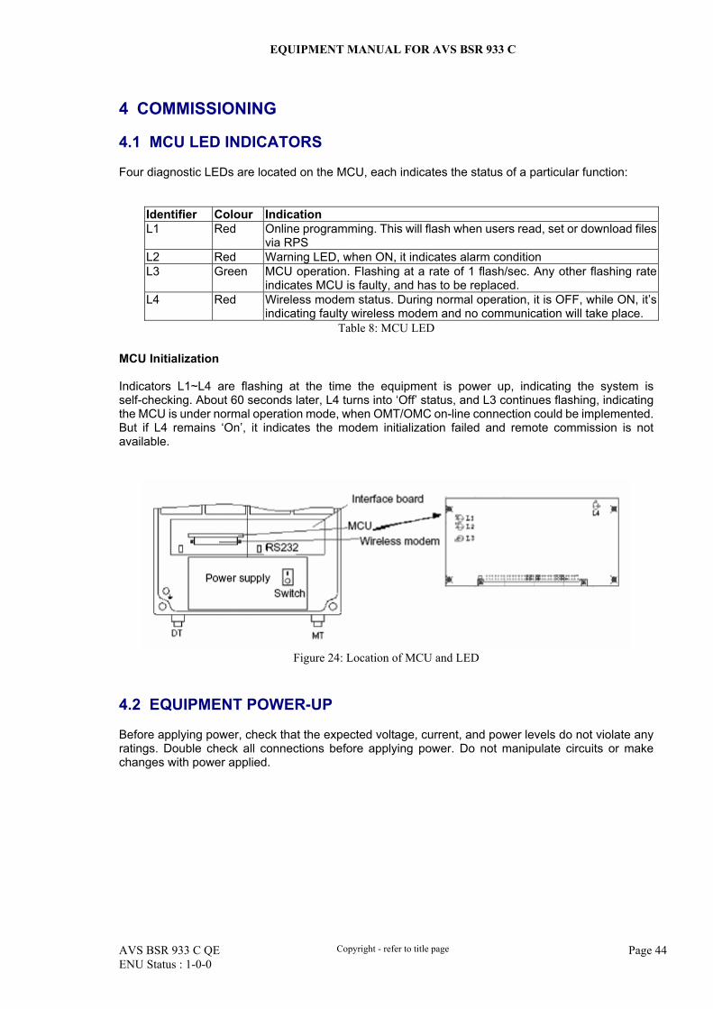
4.1 MCU LED INDICATORS
Four diagnostic LEDs are located on the MCU, each indicates the status of a particular function:
Identifier Colour Indication L1 Red Online programming. This will flash when users read, set or download files
via RPS L2 Red Warning LED, when ON, it indicates alarm condition L3 Green MCU operation. Flashing at a rate of 1 flash/sec. Any other flashing rate
indicates MCU is faulty, and has to be replaced. L4 Red Wireless modem status. During normal operation, it is OFF, while ON, it’s
indicating faulty wireless modem and no communication will take place. Table 8: MCU LED
MCU Initialization Indicators L1~L4 are flashing at the time the equipment is power up, indicating the system is self-checking. About 60 seconds later, L4 turns into ‘Off’ status, and L3 continues flashing, indicating the MCU is under normal operation mode, when OMT/OMC on-line connection could be implemented. But if L4 remains ‘On’, it indicates the modem initialization failed and remote commission is not available.
Figure 24: Location of MCU and LED
4.2 EQUIPMENT POWER-UP
Before applying power, check that the expected voltage, current, and power levels do not violate any ratings. Double check all connections before applying power. Do not manipulate circuits or make changes with power applied.
EQUIPMENT MANUAL FOR AVS BSR 933 C
AVS BSR 933 C QE Copyright - refer to title page Page 45 ENU Status : 1-0-0
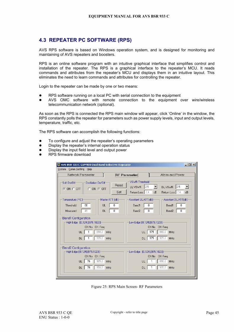
4.3 REPEATER PC SOFTWARE (RPS)
AVS RPS software is based on Windows operation system, and is designed for monitoring and maintaining of AVS repeaters and boosters. RPS is an online software program with an intuitive graphical interface that simplifies control and installation of the repeater. The RPS is a graphical interface to the repeater’s MCU. It reads commands and attributes from the repeater’s MCU and displays them in an intuitive layout. This eliminates the need to learn commands and attributes for controlling the repeater. Login to the repeater can be made by one or two means:
RPS software running on a local PC with serial connection to the equipment AVS OMC software with remote connection to the equipment over wire/wireless
telecommunication network (optional). As soon as the RPS is connected the RPS main window will appear, click ‘Online’ in the window, the RPS constantly polls the repeater for parameters such as power supply levels, input and output levels, temperature, traffic, etc. The RPS software can accomplish the following functions:
To configure and adjust the repeater’s operating parameters Display the repeater’s internal operation status Display the input field level and output power RPS firmware download
Figure 25: RPS Main Screen- RF Parameters
EQUIPMENT MANUAL FOR AVS BSR 933 C
AVS BSR 933 C QE Copyright - refer to title page Page 46 ENU Status : 1-0-0
4.4 NON-VOLATILE MEMORY
A non-volatile storage device on the MCU holds the configuration of the equipment, the following information are preserved in the event of power-loss: Repeater configuration
Repeater number Device number SMS center number Alarm dial-up number AVS OMC inquiry number Remote communication mode
Operating parameters
Master ATT Assistant ATT PA soft on/off Oscillation elimination on/off Maximum output power (output power thresholds) Channel field Alarm thresholds Temperature thresholds VSWR Single carrier Multiple carrier
EQUIPMENT MANUAL FOR AVS BSR 933 C
AVS BSR 933 C QE Copyright - refer to title page Page 47 ENU Status : 1-0-0
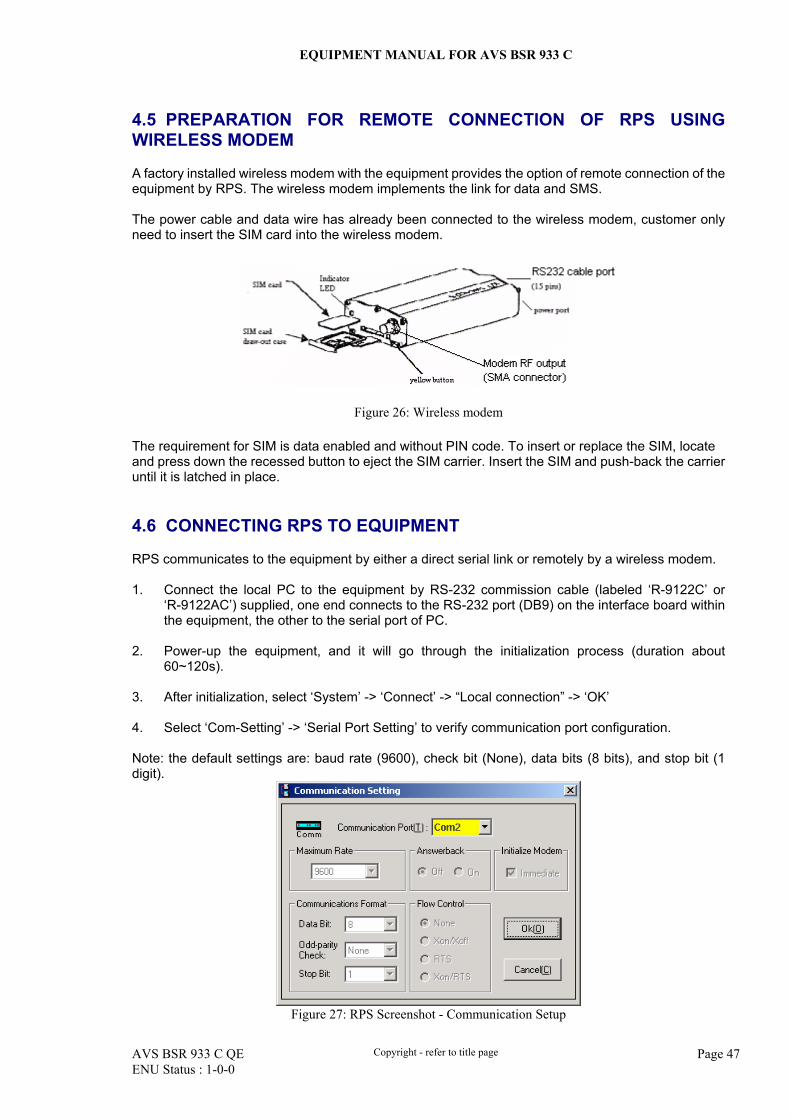
4.5 PREPARATION FOR REMOTE CONNECTION OF RPS USING WIRELESS MODEM
A factory installed wireless modem with the equipment provides the option of remote connection of the equipment by RPS. The wireless modem implements the link for data and SMS. The power cable and data wire has already been connected to the wireless modem, customer only need to insert the SIM card into the wireless modem.
Figure 26: Wireless modem
The requirement for SIM is data enabled and without PIN code. To insert or replace the SIM, locate and press down the recessed button to eject the SIM carrier. Insert the SIM and push-back the carrier until it is latched in place. 4.6 CONNECTING RPS TO EQUIPMENT
RPS communicates to the equipment by either a direct serial link or remotely by a wireless modem. 1. Connect the local PC to the equipment by RS-232 commission cable (labeled ‘R-9122C’ or
‘R-9122AC’) supplied, one end connects to the RS-232 port (DB9) on the interface board within the equipment, the other to the serial port of PC.
2. Power-up the equipment, and it will go through the initialization process (duration about
60~120s). 3. After initialization, select ‘System’ -> ‘Connect’ -> “Local connection” -> ‘OK’ 4. Select ‘Com-Setting’ -> ‘Serial Port Setting’ to verify communication port configuration. Note: the default settings are: baud rate (9600), check bit (None), data bits (8 bits), and stop bit (1 digit).
Figure 27: RPS Screenshot - Communication Setup
EQUIPMENT MANUAL FOR AVS BSR 933 C
AVS BSR 933 C QE Copyright - refer to title page Page 48 ENU Status : 1-0-0
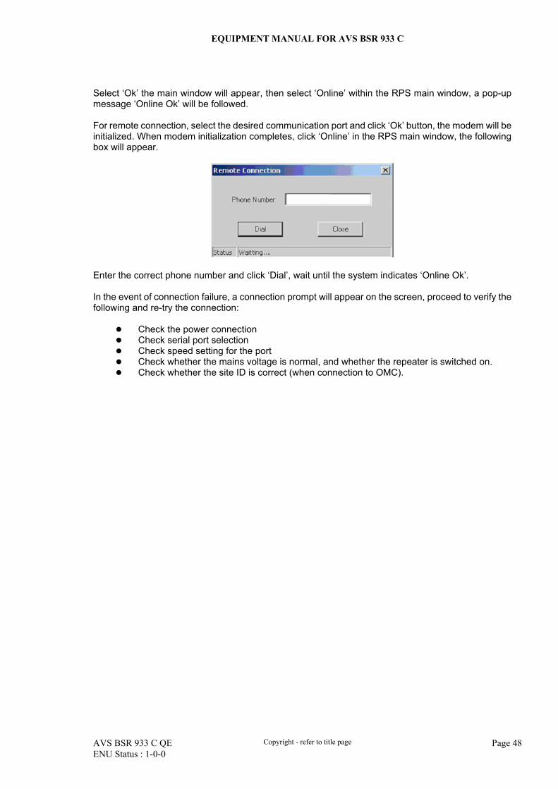
Select ‘Ok’ the main window will appear, then select ‘Online’ within the RPS main window, a pop-up message ‘Online Ok’ will be followed. For remote connection, select the desired communication port and click ‘Ok’ button, the modem will be initialized. When modem initialization completes, click ‘Online’ in the RPS main window, the following box will appear.
Enter the correct phone number and click ‘Dial’, wait until the system indicates ‘Online Ok’. In the event of connection failure, a connection prompt will appear on the screen, proceed to verify the following and re-try the connection:
Check the power connection Check serial port selection Check speed setting for the port Check whether the mains voltage is normal, and whether the repeater is switched on. Check whether the site ID is correct (when connection to OMC).
EQUIPMENT MANUAL FOR AVS BSR 933 C
AVS BSR 933 C QE Copyright - refer to title page Page 49 ENU Status : 1-0-0
4.7 LOCAL COMMISSIONING
4.7.1 USING RPS SOFTWARE
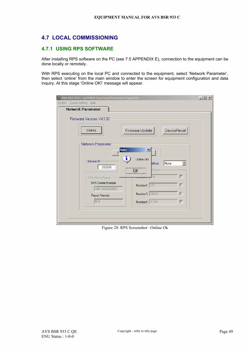
After installing RPS software on the PC (see 7.5 APPENDIX E), connection to the equipment can be done locally or remotely. With RPS executing on the local PC and connected to the equipment, select ‘Network Parameter’, then select ‘online’ from the main window to enter the screen for equipment configuration and data inquiry. At this stage ‘Online OK!’ message will appear.
Figure 28: RPS Screenshot –Online Ok
EQUIPMENT MANUAL FOR AVS BSR 933 C
AVS BSR 933 C QE Copyright - refer to title page Page 50 ENU Status : 1-0-0
4.7.2 DESCRIPTION OF PARAMETERS
The parameters being described are applicable to AVS BSR 933 C equipment having power 0.5W and 2W. 4.7.2.1 NETWORK PARAMETERS
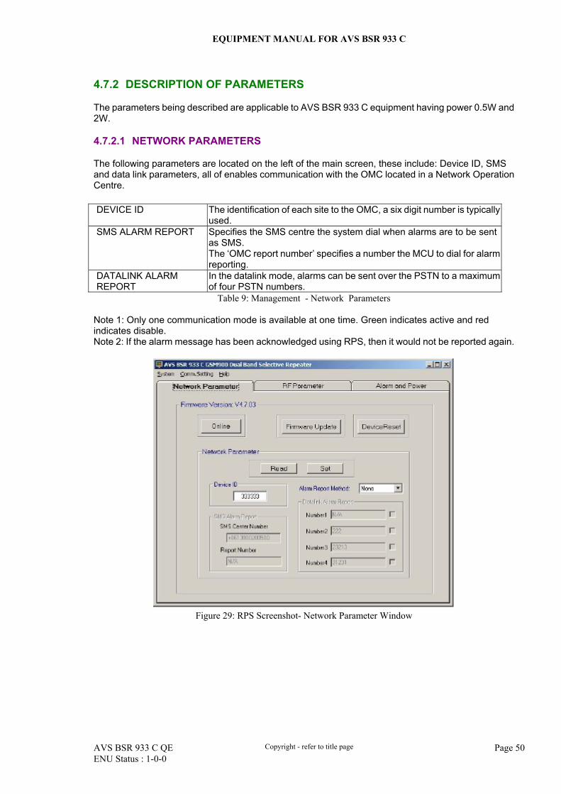
The following parameters are located on the left of the main screen, these include: Device ID, SMS and data link parameters, all of enables communication with the OMC located in a Network Operation Centre. DEVICE ID The identification of each site to the OMC, a six digit number is typically
used. SMS ALARM REPORT
Specifies the SMS centre the system dial when alarms are to be sent as SMS. The ‘OMC report number’ specifies a number the MCU to dial for alarm reporting.
DATALINK ALARM REPORT
In the datalink mode, alarms can be sent over the PSTN to a maximum of four PSTN numbers.
Table 9: Management - Network Parameters Note 1: Only one communication mode is available at one time. Green indicates active and red indicates disable. Note 2: If the alarm message has been acknowledged using RPS, then it would not be reported again.
Figure 29: RPS Screenshot- Network Parameter Window

EQUIPMENT MANUAL FOR AVS BSR 933 C
AVS BSR 933 C QE Copyright - refer to title page Page 51 ENU Status : 1-0-0
4.7.2.2 RF PARAMETERS
Occupying the middle of the main window are the RF parameters: Identifier Application Setting 1 Setting 2 Initial setting Soft On/Off Switch
To avoid the electro-magnetic emission from the repeater in operation, by enabling/ disabling the DC power supply to the frequency selecting and amplifying module. The repeater gives out no power in this case, but other parameters are not affected.
‘On' = DC power supply enabled, and the frequency selecting and amplifying module is enabled, parameters of which can be set and read.
‘Off’= no DC supply to frequency selecting and amplifying module. their parameters (frequency band, ATT, power, and alarm) can not be read or set.
ON
Oscillation Elimination On/off
To enable/disable the function that eliminates self-excited oscillation
‘On' = enable the function to eliminate the self-excited oscillation, this is done automatically by stepping down the gain when while isolation value is lower than the configured value.
‘Off' = disable the function to eliminate the self-excited oscillation.
ON
Channel number setting
To configure channel number, and allow fine tuning of frequency in steps of 25KHz.
Uplink channel numbers: High edge and low edge
Down channel numbers: High edge and low edge
Uplink freq chn high edge = 88, Downlink freq chn high edge = 66
ATT setting Adjustment to the operation gain for: Master uplink ATT, master downlink ATT, assistant uplink ATT and assistant downlink ATT.
Master uplink / downlink ATT is 0~30dB
Assistant uplink / downlink ATT is 0~15dB.
0dB for both master and assistant ATT,
Temperature threshold
Setting the upper-temperature threshold within the chassis. A measured temperature is shown.
Should the measured temperature reach the threshold, the alarm is generated.
+75c
Power threshold
For downlink power thresholdsetting ranging from +10 to +40dBm. A measures power level is shown, and customer can set power threshold according to situation.
Should the measured power value is lower than the setting, the appropriate uplink/downlink power alarm will be generated.
+12dBm
DL Field threshold
Field Intensity threshold, valid range is from –40 to –80dBm. The measured value is shown (DT port downlink input power), Customer can set field threshold according to situation.
Should the measured field value is lower than field threshold, a field-low alarm is generated.
-55dBm
Table 10: Management - RF parameters
EQUIPMENT MANUAL FOR AVS BSR 933 C
AVS BSR 933 C QE Copyright - refer to title page Page 52 ENU Status : 1-0-0
4.7.2.3 EQUIPMENT RESET
In the unlikely events of false alarms being reported or software appear to run abnormally, the customer has the option to reset the equipment. Observing the read-only fields should indicate equipment reset had completed. Select ‘System’ -> ‘Device Reset’ followed by ‘Yes’ or ‘No’ 4.7.2.4 ALARM LIST
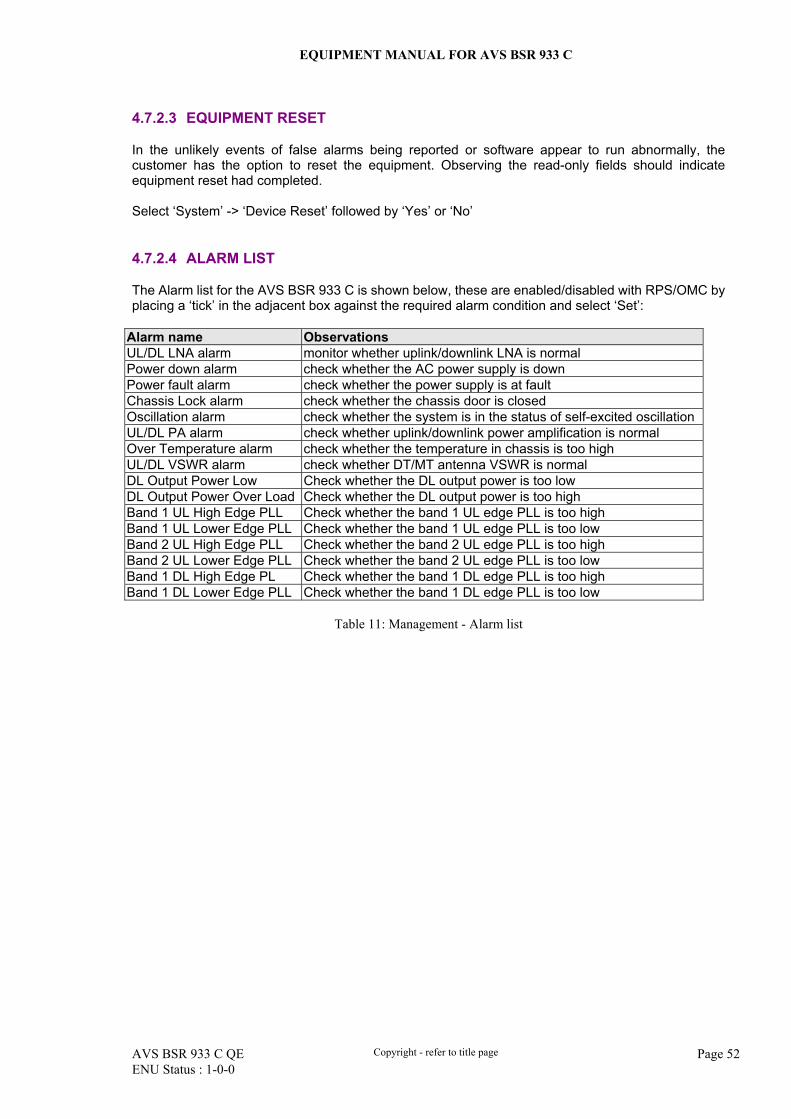
The Alarm list for the AVS BSR 933 C is shown below, these are enabled/disabled with RPS/OMC by placing a ‘tick’ in the adjacent box against the required alarm condition and select ‘Set’:
Alarm name Observations UL/DL LNA alarm monitor whether uplink/downlink LNA is normal Power down alarm check whether the AC power supply is down Power fault alarm check whether the power supply is at fault Chassis Lock alarm check whether the chassis door is closed Oscillation alarm check whether the system is in the status of self-excited oscillation UL/DL PA alarm check whether uplink/downlink power amplification is normal Over Temperature alarm check whether the temperature in chassis is too high UL/DL VSWR alarm check whether DT/MT antenna VSWR is normal DL Output Power Low Check whether the DL output power is too low DL Output Power Over Load Check whether the DL output power is too high Band 1 UL High Edge PLL Check whether the band 1 UL edge PLL is too high Band 1 UL Lower Edge PLL Check whether the band 1 UL edge PLL is too low Band 2 UL High Edge PLL Check whether the band 2 UL edge PLL is too high Band 2 UL Lower Edge PLL Check whether the band 2 UL edge PLL is too low Band 1 DL High Edge PL Check whether the band 1 DL edge PLL is too high Band 1 DL Lower Edge PLL Check whether the band 1 DL edge PLL is too low
Table 11: Management - Alarm list
EQUIPMENT MANUAL FOR AVS BSR 933 C
AVS BSR 933 C QE Copyright - refer to title page Page 53 ENU Status : 1-0-0
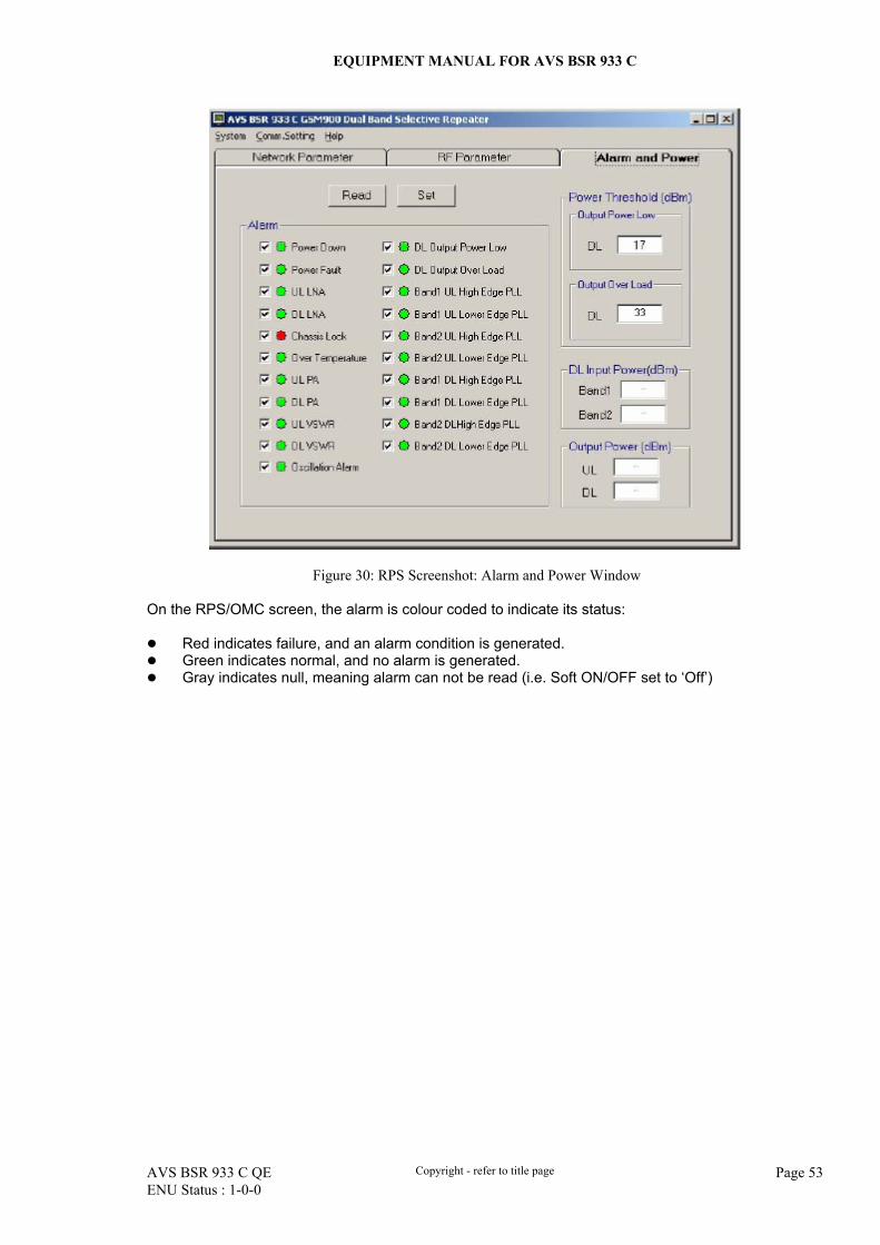
Figure 30: RPS Screenshot: Alarm and Power Window On the RPS/OMC screen, the alarm is colour coded to indicate its status:
Red indicates failure, and an alarm condition is generated. Green indicates normal, and no alarm is generated. Gray indicates null, meaning alarm can not be read (i.e. Soft ON/OFF set to ‘Off’)
EQUIPMENT MANUAL FOR AVS BSR 933 C
AVS BSR 933 C QE Copyright - refer to title page Page 54 ENU Status : 1-0-0
4.7.2.5 ALARM ACKNOWLEDGEMENT
As and when the designated Alarm occurs, it will be visible on RPS and/or reported to OMC. If OMC does not acknowledge after a time-out period of three minutes, the same alarm will be reported to OMC. After each time-out period, the un-acknowledged alarm will be reported again for a total of five attempts. Should the alarm is acknowledged within the time-out period, the alarm is deem acknowledged, and reporting stops. Alarm is cleared after the necessary diagnosis and rectification has been carried out, the on-screen colour indicator for the designated alarm should turn to green. Every twenty-four hours, the equipment will be reset automatically, any alarm messages held within the equipment would be cleared. For every five dial-up attempts, the equipment will be reset automatically, any alarm messages held within the equipment would be cleared. Should the ‘Soft on/off’ function is ‘OFF’, then no alarm will be generated for the following conditions: Power down, power failed, chassis lock and over temp alarms. 4.7.2.6 SOFTWARE DOWNLOAD
This deals with the firmware held on the MCU, download is initiated by selecting ‘Download’ in the RPS main window. The MCU firmware has its own version number. This version number is shown upper left in the RPS main window when selecting ‘Network Parameter’ . Firmware update is carried out when a new version is released, the current firmware is at release “V4.7.03”. The repeater firmware has three main tasks:
Set and configure parameters in the repeater, such as channel numbers, gain, power levels, and different report configurations
Monitor and measure alarm sources, alarm parameters and repeater utilization Send reports and alarms to the repeater RPS
4.7.2.7 SOFTWARE VERSION
AVS RPS software are designed to be backward compatible. The current version number of RPS for this equipment is V1.01. It is compatible for both 0.5W and 2W version of the repeater. To view the RPS software version, select ‘Help’ → ‘About’ in the RPS software main window.
EQUIPMENT MANUAL FOR AVS BSR 933 C
AVS BSR 933 C QE Copyright - refer to title page Page 55 ENU Status : 1-0-0
Figure 31: RPS Software Version The program can be installed from diskette or a CD. It is a Windows based application. 4.7.2.8 EXIT RPS
Click ‘Quit’ from within the ‘System’ pull-down menu within the RPS main window, select ‘Yes’, the system will exit from the RPS software.
EQUIPMENT MANUAL FOR AVS BSR 933 C
AVS BSR 933 C QE Copyright - refer to title page Page 56 ENU Status : 1-0-0
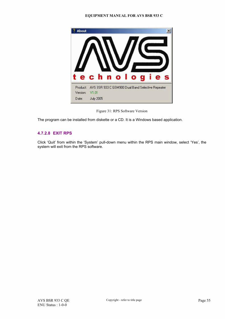
4.8 COMMISSIONING PROCEDURES
System commission can commence after the monitoring system has initialized. (e.g. when MCU LED L4 is off and L3 begin to flash). The commission sequence and procedure is as follow:
Commissioning Tasks Observation Verify RF uplink and downlink power
Locate the DT coupler at the inside left side of chassis. Measure signal from the 20dB coupling port with the DPX at the DT port to verify downlinksignals from BS. Locate the MT coupler at the right side of chassis. Measure signal from the 20dB coupling port within the DPX to verify uplink signals from mobileantenna or downlink signals retransmitted by the repeater.
On-line & inquiry status
Enter into RPS Main window. Initialization of monitoring system will be up in about 2 minutes, at that time, on MCU L4 is off and L3 begins to flash. Click ‘online’ button and inquiry the repeater’s status. Go to next step if there is no alarm. Else or, check the point of failure and handle the alarm.Set site ID and telephone number
Set On/off Status / operating band/ gain
Click ‘ON’ of power supply in the RPS main window and set high edge and low edge of the repeater’s operating frequency, uplink/downlink master ATT (user can set initial value to 20~30dB) and uplink/downlink assistant ATT (factory set value is 0dB, and it is not recommended to use assistant ATT).
Set monitoring system parameters
Test DL input power and align donor antenna
Observe DL input power from ‘Field (dBm)’. Align the direction of donor antenna till the DL input power reading is maximized.
Set monitoring system parameters
Measuring power for UL/DL output levels
Test DL output power and adjust DL ATT level
Set the DL ATT to the optimal level to avoid saturating the DL PA or to satisfy designing requirement.
Test coverage area field intensity and adjust mobile antenna.
Use test-handset to verify field intensity within the coverage area. If needed, re-align the mobile antenna to achieve the coverage as per customer requirement. Note 1: If during operation, the equipment gain could not be set to maximum or the output power is not high enough due to influence of donor antenna and mobile antenna isolation, the value of ‘Is’ should be re-calculated. If the output power has been high enough and ALC is enables, then adjust gain for the downlink branch to achieve ALC to operate within 4~7 dB. Note 2: Output power may be variable due to TDMA technology employed in GSM devices. Take the maximum value when reading parameters.
Verify uplink gain and ensure test-call is proper and there are no interfering BS
Adjust uplink gain and carryout test-call. Set the uplink gain slightly lower than downlink gain. Then carryout test call in the coverage area while adjusting uplink gain if required. Note: If the repeater locates near the BTS and the test-call performance is poor, this may be due to uplink noise interfere the BTS. Customers can calculate whether the repeater uplink noise interfere the BTS according to the table in APPENDIX C. Verify again there’s no unacceptable interference to BTS and Isolation meets the need after test-call.
Table 12: Commissioning procedures
End of section
EQUIPMENT MANUAL FOR AVS BSR 933 C
AVS BSR 933 C QE Copyright - refer to title page Page 57 ENU Status : 1-0-0
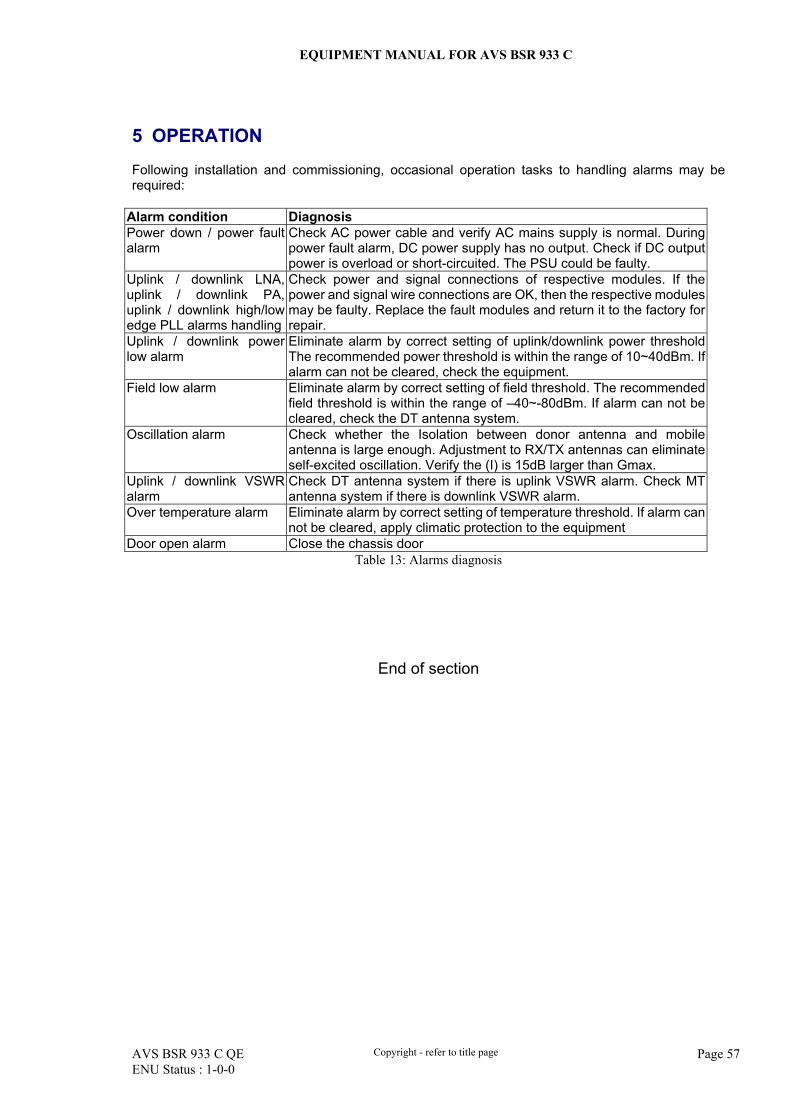
5 OPERATION
Following installation and commissioning, occasional operation tasks to handling alarms may be required:
Alarm condition Diagnosis Power down / power fault alarm
Check AC power cable and verify AC mains supply is normal. During power fault alarm, DC power supply has no output. Check if DC output power is overload or short-circuited. The PSU could be faulty.
Uplink / downlink LNA, uplink / downlink PA, uplink / downlink high/low edge PLL alarms handling
Check power and signal connections of respective modules. If the power and signal wire connections are OK, then the respective modules may be faulty. Replace the fault modules and return it to the factory for repair.
Uplink / downlink power low alarm
Eliminate alarm by correct setting of uplink/downlink power threshold The recommended power threshold is within the range of 10~40dBm. If alarm can not be cleared, check the equipment.
Field low alarm Eliminate alarm by correct setting of field threshold. The recommended field threshold is within the range of –40~-80dBm. If alarm can not be cleared, check the DT antenna system.
Oscillation alarm Check whether the Isolation between donor antenna and mobile antenna is large enough. Adjustment to RX/TX antennas can eliminate self-excited oscillation. Verify the (I) is 15dB larger than Gmax.
Uplink / downlink VSWR alarm
Check DT antenna system if there is uplink VSWR alarm. Check MT antenna system if there is downlink VSWR alarm.
Over temperature alarm Eliminate alarm by correct setting of temperature threshold. If alarm can not be cleared, apply climatic protection to the equipment
Door open alarm Close the chassis door Table 13: Alarms diagnosis
End of section
EQUIPMENT MANUAL FOR AVS BSR 933 C
AVS BSR 933 C QE Copyright - refer to title page Page 58 ENU Status : 1-0-0
6 MAINTENANCE
The AVS BSR 933 C repeater offers trouble free operation and generally does not need maintenance. The equipment operation status can be observed remotely through OMC. Periodic inspection of the repeater equipment(s) is recommended, the recommended tasks includes:
Inspect and record operation status and output power of the repeater from OMC or RPS. Verify the direction and position of antennas. Re-align if necessary. Make sure the cable gland and sealing on the RF cable connectors are not damaged. Verify lightning and grounding protection are in good condition. For MCU Li-ion back-up battery, verify its state. Deeply discharged battery shall be return to AVS
for replacement. A simple procedure to check Li-ion battery: after operating for 24-hours, switch off AC
power supply. Measure and if the voltage of Li-on battery drops below 16V within one hour, the Li-on battery has been over-discharged.

EQUIPMENT MANUAL FOR AVS BSR 933 C
AVS BSR 933 C QE Copyright - refer to title page Page 59 ENU Status : 1-0-0
7 APPENDICES
7.1 APPENDIX A: TOOLS
Recommended Tools for new installation and routine maintenance
Description Slotted screwdriver Philips screwdriver Electrically operated drill and masonary drill bit for ∅10 hole Anti-static wrist strap Ring Spanner (12~20mm) General Purpose Allen key (M5.5) Side cutter RF meter (e.g. Bird 5000)
7.2 APPENDIX B: VSWR – RETURN LOSS TABLE
VSWR - Return Loss (dB) (VSWR - RL)
VSWR - Return Loss (dB) (VSWR -RL)
VSWR - Return Loss (dB) (VSWR - RL)
1.4 -- -15.5 1.8 -- -10.9 2.2 -- -8.5 1.5 -- -14 1.9 -- -10.2 2.3 -- -8.1 1.6 -- -12.8 2.0 -- -9.6 2.4 -- -7.7 1.7 -- -11.8 2.1 -- -9 2.5 -- -7.4
7.3 APPENDIX C: UPLINK ATT AND NOISE LEVEL
Uplink Master ATT (dB)
Uplink Channel ATT (dB)
200KHz Noise Level (dBm)
0 0 -21 -10 0 -30 -20 0 -37
-30~-40 0 -40 -30~-40 -10 -47 -30~-40 -20 -50
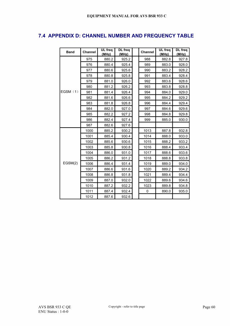
EQUIPMENT MANUAL FOR AVS BSR 933 C
AVS BSR 933 C QE Copyright - refer to title page Page 60 ENU Status : 1-0-0
7.4 APPENDIX D: CHANNEL NUMBER AND FREQUENCY TABLE
Band Channel UL freq
(MHz)DL freq(MHz) Channel UL freq
(MHz) DL freq(MHz)
975 880.2 925.2 988 882.8 927.8 976 880.4 925.4 989 883.0 928.0 977 880.6 925.6 990 883.2 928.2 978 880.8 925.8 991 883.4 928.4 979 881.0 926.0 992 883.6 928.6 980 881.2 926.2 993 883.8 928.8 981 881.4 926.4 994 884.0 929.0 982 881.6 926.6 995 884.2 929.2 983 881.8 926.8 996 884.4 929.4 984 882.0 927.0 997 884.6 929.6 985 882.2 927.2 998 884.8 929.8 986 882.4 927.4 999 885.0 930.0 987 882.6 927.6
1000 885.2 930.2 1013 887.8 932.8 1001 885.4 930.4 1014 888.0 933.0 1002 885.6 930.6 1015 888.2 933.2 1003 885.8 930.8 1016 888.4 933.4 1004 886.0 931.0 1017 888.6 933.6 1005 886.2 931.2 1018 888.8 933.8 1006 886.4 931.4 1019 889.0 934.0 1007 886.6 931.6 1020 889.2 934.2 1008 886.8 931.8 1021 889.4 934.4 1009 887.0 932.0 1022 889.6 934.6 1010 887.2 932.2 1023 889.8 934.8 1011 887.4 932.4 0 890.0 935.0 1012 887.6 932.6
EGSM(1)
EGSM(2)
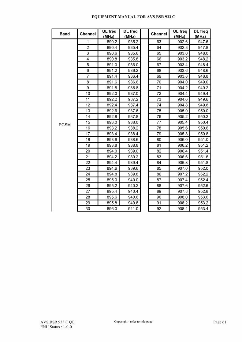
EQUIPMENT MANUAL FOR AVS BSR 933 C
AVS BSR 933 C QE Copyright - refer to title page Page 61 ENU Status : 1-0-0
Band Channel UL freq(MHz)
DL freq(MHz) Channel UL freq
(MHz) DL freq(MHz)
1 890.2 935.2 63 902.6 947.6 2 890.4 935.4 64 902.8 947.8 3 890.6 935.6 65 903.0 948.0 4 890.8 935.8 66 903.2 948.2 5 891.0 936.0 67 903.4 948.4 6 891.2 936.2 68 903.6 948.6 7 891.4 936.4 69 903.8 948.8 8 891.6 936.6 70 904.0 949.0 9 891.8 936.8 71 904.2 949.2 10 892.0 937.0 72 904.4 949.4 11 892.2 937.2 73 904.6 949.6 12 892.4 937.4 74 904.8 949.8 13 892.6 937.6 75 905.0 950.0 14 892.8 937.8 76 905.2 950.2 15 893.0 938.0 77 905.4 950.4 16 893.2 938.2 78 905.6 950.6 17 893.4 938.4 79 905.8 950.8 18 893.6 938.6 80 906.0 951.0 19 893.8 938.8 81 906.2 951.2 20 894.0 939.0 82 906.4 951.4 21 894.2 939.2 83 906.6 951.6 22 894.4 939.4 84 906.8 951.8 23 894.6 939.6 85 907.0 952.0 24 894.8 939.8 86 907.2 952.2 25 895.0 940.0 87 907.4 952.4 26 895.2 940.2 88 907.6 952.6 27 895.4 940.4 89 907.8 952.8 28 895.6 940.6 90 908.0 953.0 29 895.8 940.8 91 908.2 953.2 30 896.0 941.0 92 908.4 953.4
PGSM
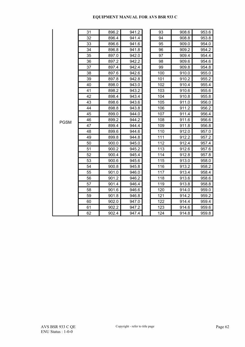
EQUIPMENT MANUAL FOR AVS BSR 933 C
AVS BSR 933 C QE Copyright - refer to title page Page 62 ENU Status : 1-0-0
31 896.2 941.2 93 908.6 953.6 32 896.4 941.4 94 908.8 953.8 33 896.6 941.6 95 909.0 954.0 34 896.8 941.8 96 909.2 954.2 35 897.0 942.0 97 909.4 954.4 36 897.2 942.2 98 909.6 954.6 37 897.4 942.4 99 909.8 954.8 38 897.6 942.6 100 910.0 955.0 39 897.8 942.8 101 910.2 955.2 40 898.0 943.0 102 910.4 955.4 41 898.2 943.2 103 910.6 955.6 42 898.4 943.4 104 910.8 955.8 43 898.6 943.6 105 911.0 956.0 44 898.8 943.8 106 911.2 956.2 45 899.0 944.0 107 911.4 956.4 46 899.2 944.2 108 911.6 956.6 47 899.4 944.4 109 911.8 956.8 48 899.6 944.6 110 912.0 957.0 49 899.8 944.8 111 912.2 957.2 50 900.0 945.0 112 912.4 957.4 51 900.2 945.2 113 912.6 957.6 52 900.4 945.4 114 912.8 957.8 53 900.6 945.6 115 913.0 958.0 54 900.8 945.8 116 913.2 958.2 55 901.0 946.0 117 913.4 958.4 56 901.2 946.2 118 913.6 958.6 57 901.4 946.4 119 913.8 958.8 58 901.6 946.6 120 914.0 959.0 59 901.8 946.8 121 914.2 959.2 60 902.0 947.0 122 914.4 959.4 61 902.2 947.2 123 914.6 959.6 62 902.4 947.4 124 914.8 959.8
PGSM
EQUIPMENT MANUAL FOR AVS BSR 933 C
AVS BSR 933 C QE Copyright - refer to title page Page 63 ENU Status : 1-0-0
7.5 APPENDIX E: RPS INSTALLATION AND UN-INSTALLATION
Operation and Maintenance Terminal (RPS) is windows-based software designed for the control and maintenance of AVS repeaters. Installed in a PC, it performs the operation on the repeater either by local connection via RS232 cable or remote connection via line/ wireless modem. Main Functions in RPS:
To configure and adjust the repeater’s operating parameters To check the repeater’s operating status To configure and detect the software network parameters Firmware download
Part A: Environment for RPS operation Before installation of RPS, ensure the following requirements for running RPS software are met. a) Minimal Hardware Requirements:
CPU : Pentium 2 processor at 300MHz or above
RAM :128MB or above
HDD: 2GB MB or above
RPS installation CD
VGA: 14 inch, with 800×600 resolution
Modem (either type may be used) Wireline modem: 56K modem, RJ11 telephone cord, RS-232 serial cable, PSU Wireless modem: Wavecom wireless modem, SIM card supporting datalink and SMS
functions, optional antenna for wireless modem, RS232 cable from modem to PC, wireless modem PSU.
Factory supplied serial cable (labeled "9122”)
b) Operating System (OS) Requirements:
English version of the following OS has been tested: Win98 SE Win Me Windows NT Workstation / Windows NT Server Windows 2000 Professional with SP1, SP2, SP3, SP4 Windows 2000 Server Edition with SP1, SP2, SP3 Windows XP Professional with SP1
Our recommendation is: Windows 2000 Professional with SP3 or SP4.
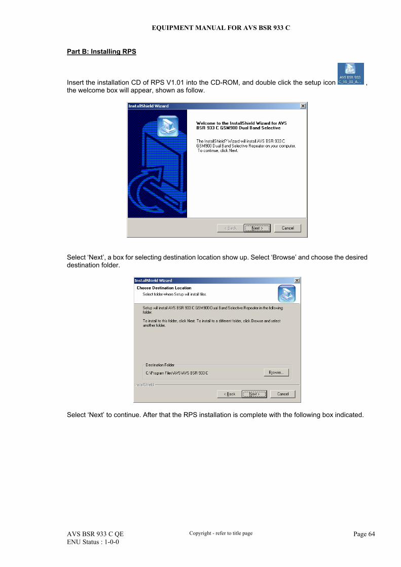
EQUIPMENT MANUAL FOR AVS BSR 933 C
AVS BSR 933 C QE Copyright - refer to title page Page 64 ENU Status : 1-0-0
Part B: Installing RPS
Insert the installation CD of RPS V1.01 into the CD-ROM, and double click the setup icon , the welcome box will appear, shown as follow.
Select ‘Next’, a box for selecting destination location show up. Select ‘Browse’ and choose the desired destination folder.
Select ‘Next’ to continue. After that the RPS installation is complete with the following box indicated.
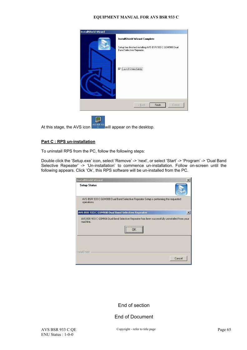
EQUIPMENT MANUAL FOR AVS BSR 933 C
AVS BSR 933 C QE Copyright - refer to title page Page 65 ENU Status : 1-0-0
At this stage, the AVS icon will appear on the desktop. Part C : RPS un-installation To uninstall RPS from the PC, follow the following steps: Double click the ‘Setup.exe’ icon, select ‘Remove’ -> ‘next’, or select ‘Start’ -> ‘Program’ -> ‘Dual Band Selective Repeater’ -> ‘Un-installation’ to commence un-installation. Follow on-screen until the following appears. Click ‘Ok’, this RPS software will be un-installed from the PC.
End of section
End of Document