AVM 105, 115: Actuator - SAUTER Controls · AVM 105, 115: Actuator How energy efficiency is...
5
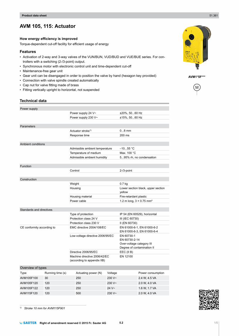
AVM 105, 115: Actuator How energy efficiency is improved Torque-dependent cut-off facility for efficient usage of energy Features • Activation of 2-way and 3-way valves of the VUN/BUN, VUD/BUD and VUE/BUE series. For con- trollers with a switching (2-/3-point) output. • Synchronous motor with electronic control unit and time-dependent cut-off • Maintenance-free gear unit • Gear unit can be disengaged in order to position the valve by hand (hexagon key provided) • Connection with valve spindle created automatically • Cap nut for valve fitting made of brass • Fitting vertically upright to horizontal, not suspended Technical data Power supply Power supply 24 V~ ±20%, 50...60 Hz Power supply 230 V~ ±15%, 50...60 Hz Parameters Actuator stroke 1) 0...8 mm Response time 200 ms Ambient conditions Admissible ambient temperature –10...55 °C Temperature of medium Max. 100 °C Admissible ambient humidity 5...95% rh, no condensation Function Control 2-/3-point Construction Weight 0.7 kg Housing Lower section black, upper section yellow Housing material Fire-retardant plastic Power cable 1.2 m long, 3 × 0.75 mm² Standards and directives Type of protection IP 54 (EN 60529), horizontal Protection class 24 V III (IEC 60730) Protection class 230 V II (EN 60730) CE conformity according to EMC directive 2004/108/EC EN 61000-6-1, EN 61000-6-2 EN 61000-6-3, EN 61000-6-4 Low-voltage directive 2006/95/EC EN 60730-1 EN 60730-2-14 Over-voltage category III Degree of contamination II Directive 2006/95/EC EEC (II B) Machine directive 2006/42/EC (according to appendix IIB) EN 12100 Overview of types Type Running time (s) Actuating power (N) Voltage Power consumption AVM105F100 30 250 230 V~ 2.4 W, 4.5 VA AVM105F120 120 250 230 V~ 2.0 W, 4.0 VA AVM105F122 120 250 24 V~ 1.6 W, 1.7 VA AVM115F120 120 500 230 V~ 2.0 W, 4.0 VA 1) Stroke 10 mm for AVM115F901 Product data sheet 51.361 Right of amendment reserved © 2015 Fr. Sauter AG 5.2 1/5 AVM1*5F***
-
Upload
trinhkhanh -
Category
Documents
-
view
218 -
download
1
Transcript of AVM 105, 115: Actuator - SAUTER Controls · AVM 105, 115: Actuator How energy efficiency is...
AVM 105, 115: Actuator
How energy efficiency is improvedTorque-dependent cut-off facility for efficient usage of energy
Features• Activation of 2-way and 3-way valves of the VUN/BUN, VUD/BUD and VUE/BUE series. For con-
trollers with a switching (2-/3-point) output.• Synchronous motor with electronic control unit and time-dependent cut-off• Maintenance-free gear unit• Gear unit can be disengaged in order to position the valve by hand (hexagon key provided)• Connection with valve spindle created automatically• Cap nut for valve fitting made of brass• Fitting vertically upright to horizontal, not suspended
Technical data
Power supplyPower supply 24 V~ ±20%, 50...60 HzPower supply 230 V~ ±15%, 50...60 Hz
ParametersActuator stroke1) 0...8 mmResponse time 200 ms
Ambient conditionsAdmissible ambient temperature –10...55 °CTemperature of medium Max. 100 °CAdmissible ambient humidity 5...95% rh, no condensation
FunctionControl 2-/3-point
ConstructionWeight 0.7 kgHousing Lower section black, upper section
yellowHousing material Fire-retardant plasticPower cable 1.2 m long, 3 × 0.75 mm²
Standards and directivesType of protection IP 54 (EN 60529), horizontalProtection class 24 V III (IEC 60730)Protection class 230 V II (EN 60730)
CE conformity according to EMC directive 2004/108/EC EN 61000-6-1, EN 61000-6-2EN 61000-6-3, EN 61000-6-4
Low-voltage directive 2006/95/EC EN 60730-1EN 60730-2-14Over-voltage category IIIDegree of contamination II
Directive 2006/95/EC EEC (II B)Machine directive 2006/42/EC (according to appendix IIB)
EN 12100
Overview of typesType Running time (s) Actuating power (N) Voltage Power consumption
AVM105F100 30 250 230 V~ 2.4 W, 4.5 VA
AVM105F120 120 250 230 V~ 2.0 W, 4.0 VA
AVM105F122 120 250 24 V~ 1.6 W, 1.7 VA
AVM115F120 120 500 230 V~ 2.0 W, 4.0 VA
1) Stroke 10 mm for AVM115F901
Product data sheet 51.361
Right of amendment reserved © 2015 Fr. Sauter AG 5.2 1/5
AVM1*5F***
Type Running time (s) Actuating power (N) Voltage Power consumption
AVM115F122 120 500 24 V~ 1.6 W, 1.7 VA
AVM115F901 160 500 230 V~ 2.0 W, 4.0 VA
A AVM115F901: For SAUTER Valveco VCL040 and VCL050, inverse scale, inverse connection
A KTM 512, TA-Regulator DN 15...50
AccessoriesType Description
0372145001 Auxiliary change-over contacts, single
0372145002 Auxiliary change-over contacts, double
0372249001 Adaptor required when media temperature > 100 °C (recommended for temperatures < 10 °C)
0372273001 Adapter for Siemens valve VVG/VXG 44, 48
0372286001 Potentiometer, 130 Ω
0372286002 Potentiometer, 1000 Ω
0372286003 Potentiometer, 5000 Ω
0372320001 Hexagon key as visualisation for position indicator
0372459100 External switching, 230 V version for parallel operation with A*M 1*4 or actuators with endswitch, incl. junction box
0372459102 External switching, 24 V version for parallel operation with A*M 1*4 or actuators with endswitch, incl. junction box
A Auxiliary change-over contacts: Infinitely variable 0...100°, admissible load 5(2) A, 24...230 V
A Potentiometers: Only one potentiometer or one set of auxiliary contacts can be fitted for each actuator
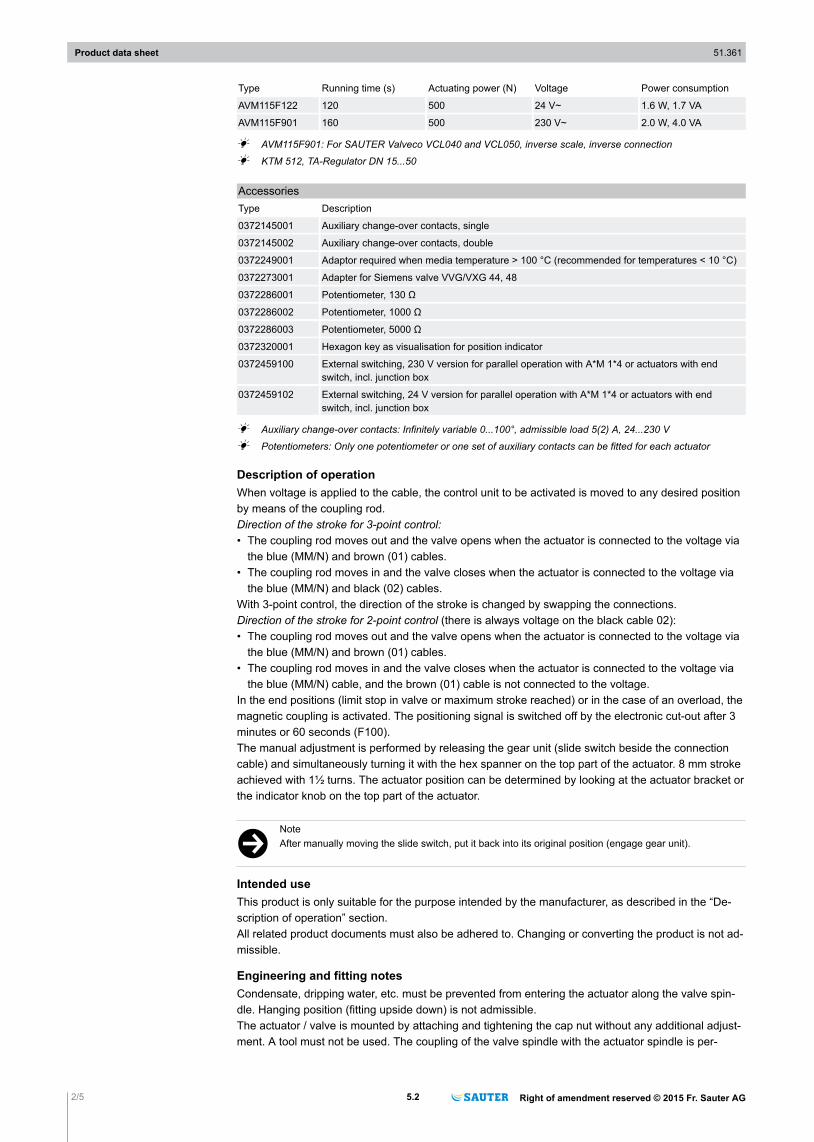
Description of operationWhen voltage is applied to the cable, the control unit to be activated is moved to any desired positionby means of the coupling rod.Direction of the stroke for 3-point control:• The coupling rod moves out and the valve opens when the actuator is connected to the voltage via
the blue (MM/N) and brown (01) cables.• The coupling rod moves in and the valve closes when the actuator is connected to the voltage via
the blue (MM/N) and black (02) cables.With 3-point control, the direction of the stroke is changed by swapping the connections.Direction of the stroke for 2-point control (there is always voltage on the black cable 02):• The coupling rod moves out and the valve opens when the actuator is connected to the voltage via
the blue (MM/N) and brown (01) cables.• The coupling rod moves in and the valve closes when the actuator is connected to the voltage via
the blue (MM/N) cable, and the brown (01) cable is not connected to the voltage.In the end positions (limit stop in valve or maximum stroke reached) or in the case of an overload, themagnetic coupling is activated. The positioning signal is switched off by the electronic cut-out after 3minutes or 60 seconds (F100).The manual adjustment is performed by releasing the gear unit (slide switch beside the connectioncable) and simultaneously turning it with the hex spanner on the top part of the actuator. 8 mm strokeachieved with 1½ turns. The actuator position can be determined by looking at the actuator bracket orthe indicator knob on the top part of the actuator.
)NoteAfter manually moving the slide switch, put it back into its original position (engage gear unit).
Intended useThis product is only suitable for the purpose intended by the manufacturer, as described in the “De-scription of operation” section.All related product documents must also be adhered to. Changing or converting the product is not ad-missible.
Engineering and fitting notesCondensate, dripping water, etc. must be prevented from entering the actuator along the valve spin-dle. Hanging position (fitting upside down) is not admissible.The actuator / valve is mounted by attaching and tightening the cap nut without any additional adjust-ment. A tool must not be used. The coupling of the valve spindle with the actuator spindle is per-
Product data sheet 51.361
2/5 5.2 Right of amendment reserved © 2015 Fr. Sauter AG
formed automatically, either by using the manual adjustment and moving to 100% stroke or by con-necting the voltage to terminals MM/N and 01. When dismantling, first the actuator and valve spindlesare released, then the cap nut. The device is delivered ex works in the middle position.The concept of synchronous motor and magnetic coupling enables parallel operation of multiple valveactuators of the same type.The maximum accessory equipment for an actuator is 1 auxiliary change-over contact or 1 potentiom-eter.The auxiliary contact accessory is screwed onto the top cover of the actuator. To be able to make themechanical connection, you first have to remove the indicator knob. A new indicator can be seen onthe cover of the accessory.
!Beware of injuryOpening the housing creates a risk of injury.►The housing must not be opened.
Additional technical dataThe upper section of the housing with the cover and indicator knob contains the synchronous motorwith capacitor.The lower section of the housing contains the maintenance-free gear unit and the gear-release knob.
Auxiliary change-over contacts:• Switch rating max. 230 V VAC, current min. 20 mA at 20 V• Switch rating max. 4...30 V VDC, current 1...100 mA
Power consumptionType Running time [s] Status Active power P [W] Apparent power S [VA]AVM105F100 30 Operation 2.4 5.4AVM105F120 120 Operation 2.0 5.0AVM105F122 120 Operation 1.6 1.7AVM115F120 120 Operation 2.0 5.0AVM115F122 120 Operation 1.6 1.7
Outdoor installationThe actuators must also be protected from the weather if they are installed outside the building.
DisposalWhen disposing of the product, observe the currently applicable local laws.More information on materials can be found in the Declaration on materials and the environment forthis product.
Connection diagram
F. . 2 = 24V~
MM/N 01 02
M
BKBNBU
A1
04
68
2-Pt.
F. . 0 = 230V~ F. . 2 = 24V~
BKBNBU
A1
04
69
a
3-Pt: F. . 0 = 230V~
MM/N 01 02
M
Product data sheet 51.361
Right of amendment reserved © 2015 Fr. Sauter AG 5.2 3/5
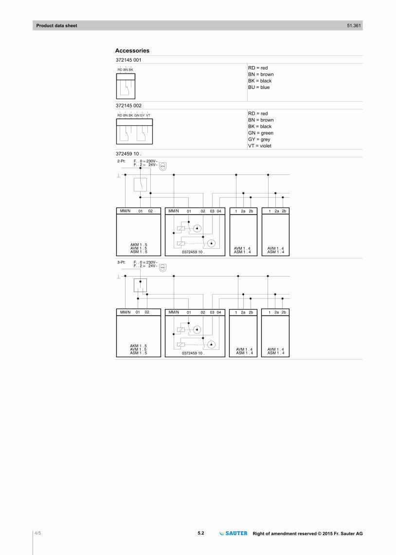
Accessories372145 001
RD BN BKRD = redBN = brownBK = blackBU = blue
372145 002
RD BN BK GN GY VTRD = redBN = brownBK = blackGN = greenGY = greyVT = violet
372459 10 .
MM/N 01 02 03 04 1 2a 2b 1 2a 2b
2-Pt: F. . 0 = 230V~F. . 2 = 24V~
MM/N 01 02
0372459 10 .
AKM 1 . 5AVM 1 . 5ASM 1 . 5
AVM 1 . 4ASM 1 . 4
AVM 1 . 4ASM 1 . 4
MM/N 01 02 03 04 1 2a 2b 1 2a 2b
3-Pt: F. . 0 = 230V~F. . 2 = 24V~
MM/N 01 02
0372459 10 .
AVM 1 . 4ASM 1 . 4
AVM 1 . 4ASM 1 . 4
AKM 1 . 5AVM 1 . 5ASM 1 . 5
Product data sheet 51.361
4/5 5.2 Right of amendment reserved © 2015 Fr. Sauter AG
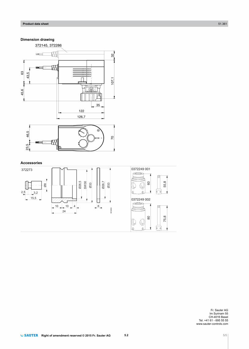
Dimension drawing
43,5
35
1221
07
,17
046,5
23,5
126,7
63
45,6
32
372145, 372286
Accessories
372273
M10
20
3
Ø33
Ø26
,7
SW
30
Ø33
Ø26
,5
810 10 4
24
15,5
3,22,5
Ø8 60
55,8
80
75,8
0372249 002
0372249 001
Product data sheet 51.361
Right of amendment reserved © 2015 Fr. Sauter AG 5.2 5/5
Fr. Sauter AGIm Surinam 55
CH-4016 BaselTel. +41 61 - 695 55 55
www.sauter-controls.com


![Original Operating Manual Electric Actuator NA · Original Operating Manual Electric Actuator NA acc. to annex VI of the Directive 2006/42/EC [Kontakt] Watergates GmbH & Co. KG Postfach](https://static.fdocuments.net/doc/165x107/6056218ccac09d06814c7fae/original-operating-manual-electric-actuator-na-original-operating-manual-electric.jpg)
