AVK SEriES 851 SinglE & doublE orificE Air rElEASE VAlVES ...
14
AVK SERIES 851 SINGLE & DOUBLE ORIFICE AIR RELEASE VALVES (WATER) INSTALLATION, OPERATION & MAINTENANCE MANUAL Instruction for use Thank you for selecting an AVK product. With correct use, the product is guaranteed to deliver a long and reliable service. This manual has been prepared to assist you with the installation, operation and maintenance of the valve to the maximum efficiency. For ease of reference, it has been divided into sections covering all aspects of use, and it is in the users best interests to read it and ensure that it is fully understood. Health and Safety It is always recommended that wherever work is being carried out on a valve that the valve is fully depressurised prior to carrying it out, and for the convenience draining of the line may be beneficial. It is essential that the user of the valve is aware of the weight of the components and/or assembles that must be handled and manipulated during installation and maintenance. It is the users responsibility to ensure that safe working practices are followed at all times. Whenever AVK products are installed, operated, or maintained, it is essential that the staff that undertake these operations be adequately trained. The hazards of pressurised liquids and gases can be severe, and it is the responsibility of the users to ensure that trained, competent staff undertake these duties. This manual has been designed to assist, but it can never fully replace quality training in the workplace. AVK technical staff will always be available to answer any questions relating to specific problems that may not be covered by this manual. AVK products are designed and manufactured to be fit for purpose, and to a high and reliable standard. This provides a safe product with minimum risk to health when used correctly for the purpose for which it was designed. However, this assumes that the equipment is used and maintained in accordance with the manual, and the user is advised to study this manual, and to make it available to all staff that may need to refer to it. AVK cannot be held responsible for any incidents arising from incorrect installation, operation or maintenance. The responsibility for this must rest wholly with the user. AVK Valves Pty Ltd, 559A Grand Junction Road, Wingfield, SA 5013, Australia - T: +61 8 8368 0900 - E: [email protected] - W: www.avkcivil.com.au Version number 3 COPYRIGHT©AVK GROUP A/S 2017 pp. 1 of 14
Transcript of AVK SEriES 851 SinglE & doublE orificE Air rElEASE VAlVES ...

AVK SEriES 851 SinglE & doublE orificE Air rElEASE VAlVES (wAtEr)inStAllAtion, opErAtion & mAintEnAncE mAnuAl
instruction for use Thank you for selecting an AVK product. With correct use, the product is guaranteed to deliver a long and reliable service. This manual has been prepared to assist you with the installation, operation and maintenance of the valve to the maximum efficiency. For ease of reference, it has been divided into sections covering all aspects of use, and it is in the users best interests to read it and ensure that it is fully understood.
Health and Safety It is always recommended that wherever work is being carried out on a valve that the valve is fully depressurised prior to carrying it out, and for the convenience draining of the line may be beneficial.
It is essential that the user of the valve is aware of the weight of the components and/or assembles that must be handled and manipulated during installation and maintenance. It is the users responsibility to ensure that safe working practices are followed at all times.
Whenever AVK products are installed, operated, or maintained, it is essential that the staff that undertake these operations be adequately trained. The hazards of pressurised liquids and gases can be severe, and it is the responsibility of the users to ensure that trained, competent staff undertake these duties. This manual has been designed to assist, but it can never fully replace quality training in the workplace. AVK technical staff will always be available to answer any questions relating to specific problems that may not be covered by this manual.
AVK products are designed and manufactured to be fit for purpose, and to a high and reliable standard. This provides a safe product with minimum risk to health when used correctly for the purpose for which it was designed. However, this assumes that the equipment is used and maintained in accordance with the manual, and the user is advised to study this manual, and to make it available to all staff that may need to refer to it.
AVK cannot be held responsible for any incidents arising from incorrect installation, operation or maintenance. The responsibility for this must rest wholly with the user.
AVK Valves Pty Ltd, 559A Grand Junction Road, Wingfield, SA 5013, Australia - T: +61 8 8368 0900 - E: [email protected] - W: www.avkcivil.com.au Version number 3COPYRIGHT©AVK GROUP A/S 2017 pp. 1 of 14

AVK SEriES 851 SinglE & doublE orificE Air rElEASE VAlVES (wAtEr)inStAllAtion, opErAtion & mAintEnAncE mAnuAl
Storage• Protection against weather should be provided. Ideally, valves should be kept indoors with the actual valve temperature
always higher than the dew point.
• If outdoor storage is unavoidable the valves should then be supported off the ground and protected by a weatherproof cover, from dust-laden damp or saline conditions and at an ambient temperature.
• If long term storage is envisaged, then it may be considered prudent to have a AVK engineer inspect the valve prior to
installation.
Handling
A basic consideration in handling protected valves should be to avoid damaging the coating protection and valves should never be thrown or dropped. Valves whose size requires handling by crane or lift truck should be slung or rigged carefully to avoid damage to exposed valve parts.
AVK Valves Pty Ltd, 559A Grand Junction Road, Wingfield, SA 5013, Australia - T: +61 8 8368 0900 - E: [email protected] - W: www.avkcivil.com.au Version number 3COPYRIGHT©AVK GROUP A/S 2017 pp. 1 of 14
AVK Valves Pty Ltd, 559A Grand Junction Road, Wingfield, SA 5013, Australia - T: +61 8 8368 0900 - E: [email protected] - W: www.avkcivil.com.au Version number 3COPYRIGHT©AVK GROUP A/S 2017 pp. 2 of 14

AVK SEriES 851 SinglE & doublE orificE Air rElEASE VAlVES (wAtEr)inStAllAtion, opErAtion & mAintEnAncE mAnuAl
1. introduction
AVK air release valves can be fitted to any peak on a pipeline where the pressure is greater than 0.1 bar and up to the maximum working pressure. The dual orifice air release valves operation is completely automatic and are capable of fulfilling the venting requirement of the pipeline and release any air or gas under pressure which has accumulated in the system without any manual aid.
When fitted with a vented non return kit the valve will allow air to be drawn into a pipeline normally during the process of de-watering. The high inflow rate is to prevent damaging vacuum pressure from developing.
When air or gas pressure in the pipeline increases relative to the atmospheric pressure on outflow conditions, the main aperture will close and controlled emission of gasses will occur through the cent-regulating valve, until the main valve closes.
When fitted with the in-flow check valve kit the valve will allow outflow of air when fillinf the pipeline but will not allow inflow of air when de-watering.
materials:castings (body, bonnet and cowl)Ductile Iron, grade 500-7 to AS 1831
SealsEPDM WBS listed
coatingFusion bonded epoxy (FBE)
fastenersStainless Steel
Refer to datasheeta for specific information
Single orifice Air Valve
double orifice Air Valve
AVK Valves Pty Ltd, 559A Grand Junction Road, Wingfield, SA 5013, Australia - T: +61 8 8368 0900 - E: [email protected] - W: www.avkcivil.com.au Version number 3COPYRIGHT©AVK GROUP A/S 2017 pp. 3 of 14
AVK SEriES 851 SinglE & doublE orificE Air rElEASE VAlVES (wAtEr)inStAllAtion, opErAtion & mAintEnAncE mAnuAl
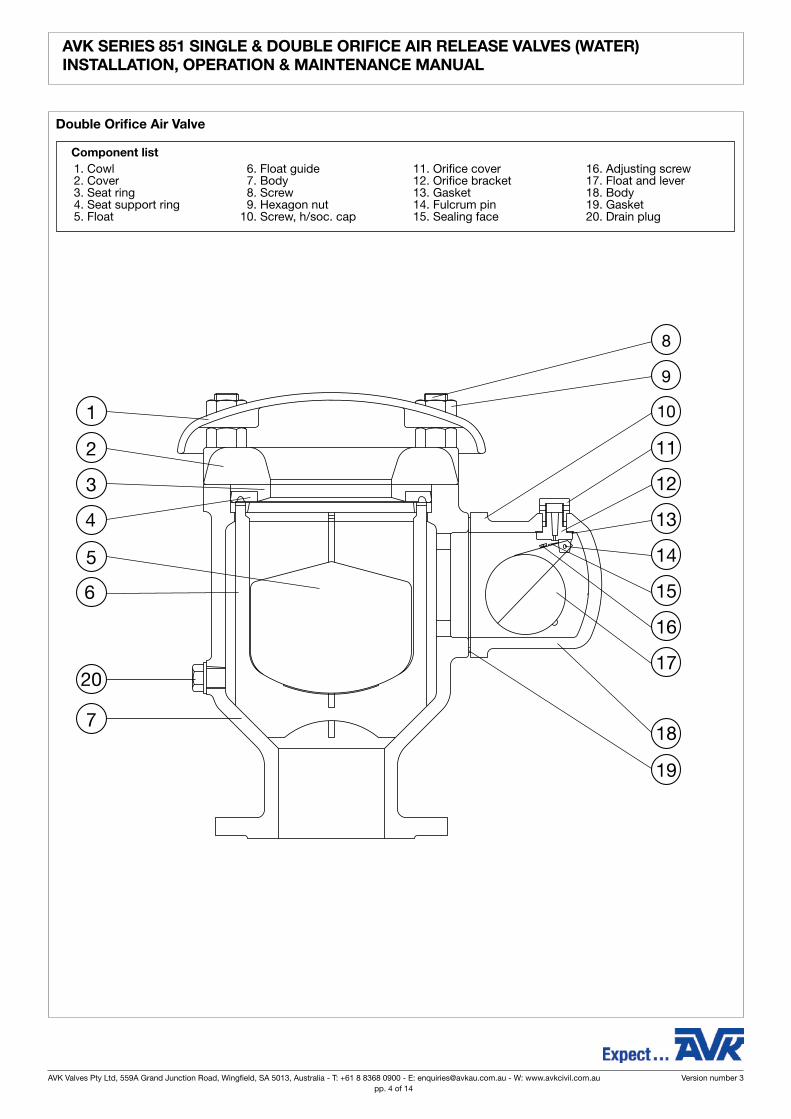
double orifice Air Valve
component list 1. Cowl 2. Cover 3. Seat ring 4. Seat support ring 5. Float
6. Float guide 7. Body 8. Screw 9. Hexagon nut 10. Screw, h/soc. cap
11. Orifice cover 12. Orifice bracket 13. Gasket 14. Fulcrum pin 15. Sealing face
16. Adjusting screw 17. Float and lever 18. Body 19. Gasket 20. Drain plug
1
2
4
7
5
10
11
6
3
13
14
15
16
17
18
19
12
9
8
20
AVK Valves Pty Ltd, 559A Grand Junction Road, Wingfield, SA 5013, Australia - T: +61 8 8368 0900 - E: [email protected] - W: www.avkcivil.com.au Version number 3COPYRIGHT©AVK GROUP A/S 2017 pp. 3 of 14
AVK Valves Pty Ltd, 559A Grand Junction Road, Wingfield, SA 5013, Australia - T: +61 8 8368 0900 - E: [email protected] - W: www.avkcivil.com.au Version number 3COPYRIGHT©AVK GROUP A/S 2017 pp. 4 of 14

AVK SEriES 851 SinglE & doublE orificE Air rElEASE VAlVES (wAtEr)inStAllAtion, opErAtion & mAintEnAncE mAnuAl
Single orifice Air Valve
component list 1. Body 2. Cover 3. Orifice bracket 4. Orifice cover
5. Gasket 6. Grooved pin 7. Float 8. O-ring
9. Washer 10. Nut 11. Hex bolt
AVK Valves Pty Ltd, 559A Grand Junction Road, Wingfield, SA 5013, Australia - T: +61 8 8368 0900 - E: [email protected] - W: www.avkcivil.com.au Version number 3COPYRIGHT©AVK GROUP A/S 2017 pp. 5 of 14

AVK SEriES 851 SinglE & doublE orificE Air rElEASE VAlVES (wAtEr)inStAllAtion, opErAtion & mAintEnAncE mAnuAl
2. installation
• These valves can be fitted on any peak on a pipeline where the pressure is greater than 0.1 bar and up to the maximum working pressure.
• They should be installed in a vertical position to allow smooth float movement and proper seating on the large Orifice valve, and to ensure that the lever operated small Orifice valve will seal the orifice efficiently and also re-open for air release under the correct working conditions.
• The space round the valve should be kept free of any obstructions which would prevent the free flow of air.
• When the valves are located below ground level, ample venting area should be provided for discharging and admitting large volumes of air during pipe filling and emptying operations.
• It is recommended that an isolating gate valve be fitted between the valve an the pipeline - if fitted with a butterfly valve it should incorporate a gearbox operator to ensure slow closure and opening of the valve.
• Tighten bolts in a diagonal sequence to ensure flanges are pulled parallel.
• Finally tighten bolts to correct torque levels as recommended in WSA 109.
AVK Valves Pty Ltd, 559A Grand Junction Road, Wingfield, SA 5013, Australia - T: +61 8 8368 0900 - E: [email protected] - W: www.avkcivil.com.au Version number 3COPYRIGHT©AVK GROUP A/S 2017 pp. 5 of 14
AVK Valves Pty Ltd, 559A Grand Junction Road, Wingfield, SA 5013, Australia - T: +61 8 8368 0900 - E: [email protected] - W: www.avkcivil.com.au Version number 3COPYRIGHT©AVK GROUP A/S 2017 pp. 6 of 14

AVK SEriES 851 SinglE & doublE orificE Air rElEASE VAlVES (wAtEr)inStAllAtion, opErAtion & mAintEnAncE mAnuAl
3. operation
3.1. Valve operation
These valves are completely automatic in operation and are capable of fulfilling the venting requirement of the pipeline and will release any air or gas under pressure which has accumulated in the system without any manual aid.
3.1. Valves with Vented non return unit
When the pressure in the pipeline is below atmospheric the valve disc will rise to open the valve and allow air intake. When the pressure increases the disc will fall and seal off the main aperture while controlled air emission takes place through the vent hole via the regulating valve.
The regulating valve is set for maximum emission. If a reduced air emission is required, the regulating valve should be turned anti-clockwise. A slot is provided for regulating purposes. If when the regulating valve is at its maximum setting (i.e. full in) and the air emission is still insufficient, the regulating valve may be removed completely thereby giving increased air flow capacity but of course no regulation is now possible.
3.2. Valves with in-flow check unit
When the pressure in the pipeline is below atmospheric the valve disc will drop to close the valve and allow no air intake. When line pressure increases the disc will rise and open the aperture with no controlling of the air emission rate.
AVK Valves Pty Ltd, 559A Grand Junction Road, Wingfield, SA 5013, Australia - T: +61 8 8368 0900 - E: [email protected] - W: www.avkcivil.com.au Version number 3COPYRIGHT©AVK GROUP A/S 2017 pp. 7 of 14

AVK SEriES 851 SinglE & doublE orificE Air rElEASE VAlVES (wAtEr)inStAllAtion, opErAtion & mAintEnAncE mAnuAl
4. options
AVK Series 851 Air Valves can be supplied fitted with the following options and all options are available as retrofit kit.
Options include:
- Vented non-return kit
- Inflow check unit
- Vent pipe for small orifice
Options such as strainers and non-return valves can also be fitted.
4.1. installation of Vented non return Kit/unit
1. Slacken and remove blots and nuts from body/cover/cowl of exisiting air release valve.
2. Remove cover and cowl from exisiting air release valve.
3. Mount non return valve assembly on top of exisiting air release valve body.
4. Fit and tighten studs and nuts to hold assembly in position on body.
4.2. installation of Vent pipe (where specified)
1. Parts as supplied.
2. Screw in male connector by hand until firm (Use a sealant or thread tape to seal).
AVK Valves Pty Ltd, 559A Grand Junction Road, Wingfield, SA 5013, Australia - T: +61 8 8368 0900 - E: [email protected] - W: www.avkcivil.com.au Version number 3COPYRIGHT©AVK GROUP A/S 2017 pp. 7 of 14
AVK Valves Pty Ltd, 559A Grand Junction Road, Wingfield, SA 5013, Australia - T: +61 8 8368 0900 - E: [email protected] - W: www.avkcivil.com.au Version number 3COPYRIGHT©AVK GROUP A/S 2017 pp. 8 of 14

AVK SEriES 851 SinglE & doublE orificE Air rElEASE VAlVES (wAtEr)inStAllAtion, opErAtion & mAintEnAncE mAnuAl
AVK Valves Pty Ltd, 559A Grand Junction Road, Wingfield, SA 5013, Australia - T: +61 8 8368 0900 - E: [email protected] - W: www.avkcivil.com.au Version number 3COPYRIGHT©AVK GROUP A/S 2017 pp. 9 of 14
3. Hold air valve discharge fitting with appropriate spanner. This ensures that it will not turn and over tighten. (If this is not done and over tightening occurs this will distort the internal fitting and may jam the float which will not operate correctly).
4. Use appropriate sized spanner to tighten the male connector body.
5. Insert stainless steel tube ensuring it bottoms out on male connector, use appropriate size spanner to tighten ferule nut while insuring the male connector body is held in position as not to turn.
note force to tighten should always be spanner to spanner never spanner to fitting this ensures no over tightening or movement of existing fittings which may cause leakage or damage.

AVK SEriES 851 SinglE & doublE orificE Air rElEASE VAlVES (wAtEr)inStAllAtion, opErAtion & mAintEnAncE mAnuAl
AVK Valves Pty Ltd, 559A Grand Junction Road, Wingfield, SA 5013, Australia - T: +61 8 8368 0900 - E: [email protected] - W: www.avkcivil.com.au Version number 3COPYRIGHT©AVK GROUP A/S 2017 pp. 10 of 14

AVK SEriES 851 SinglE & doublE orificE Air rElEASE VAlVES (wAtEr)inStAllAtion, opErAtion & mAintEnAncE mAnuAl
AVK Valves Pty Ltd, 559A Grand Junction Road, Wingfield, SA 5013, Australia - T: +61 8 8368 0900 - E: [email protected] - W: www.avkcivil.com.au Version number 3COPYRIGHT©AVK GROUP A/S 2017 pp. 11 of 14

AVK SEriES 851 SinglE & doublE orificE Air rElEASE VAlVES (wAtEr)inStAllAtion, opErAtion & mAintEnAncE mAnuAl
5. maintenance
5.1 The cover bolts on the large orifice valve and the nuts holding the small Orifice valve to the main body should be checked occasionally for tightness especially where the valve is subject to vibration (Bolt torque 40Nm).
Isolate the valve, drain the remaining water via the drain plug and dismantle both the large and small Orifice valves for examina-tion.
5.2 Remove the cover and cover, withdraw the plastic float, guide assembly, seat ring and rubber seal ring.
If on examination any of these components show signs of cracking, ageing etc, replacement is necessary.
Careful examination is required at the float sealing edge of the rubber seal ring and also on the outside rim which acts as a static cover seal.
5.3 Any growth formed within the valve should be removed.
Surface corrosion on the machined recess on the top of the body should be removed with emery, and its surface smeared with silicon grease (MOLYKOTE 111).
5.4 Assembly consists of locating the float guide with float into the recess. Assemble the rubber seal ring on the plastic seat ring with the plain rubber face, towards the plastic seat. Place both into recess on the top of the guide ring, rubber face down, using a slightly turning motion. Replace the cover and tighten down metal to metal. Fit the cowl.
5.5 The float guide assembly consists of 3 pieces, the ‘U’ legs sit on the cone shape above the body throat, thus transmitting float impact direct to the body. The top ring is assembled with large inside diameter of the taper facing into the valve, the ‘U’ legs located in this top ring but free to be pushed down to touch the taper in the body.
Small Orifice
5.6 The small Orifice valve body should be unbolted from the large orifice valve, the float and orifice bracket assembly removed after unscrewing the orifice cover and the following points examined.
5.7 Check the float for freedom of movement and inspect the fulcrum pin and bearing, on the glass filled nylon lugs for excessive wear.
5.8. Inspect the rubber seat in the float lever for deterioration or excessive premanent set. In the early valve types the seats are held in position by interference ribs in the recess. These can simply be inverted into the recess to obtain a new sealing surface.
The later types are bonded using a M.E.K. solvent. If removal is necessary, the rubber must be removed and a new seat solvent cemented in position.
5.9 Adjusting screw
The purpose of this screw is to limit the degree of compression by the orifice sealing lip on the rubber face.
It is set at the initial assembly so that when the orifice is just seating, there is a clearance of 0.7 to 1mm (0.030” to 0.040”) between the top of the orifice bracket. This would not normally require resetting.
AVK Valves Pty Ltd, 559A Grand Junction Road, Wingfield, SA 5013, Australia - T: +61 8 8368 0900 - E: [email protected] - W: www.avkcivil.com.au Version number 3COPYRIGHT©AVK GROUP A/S 2017 pp. 11 of 14
AVK Valves Pty Ltd, 559A Grand Junction Road, Wingfield, SA 5013, Australia - T: +61 8 8368 0900 - E: [email protected] - W: www.avkcivil.com.au Version number 3COPYRIGHT©AVK GROUP A/S 2017 pp. 12 of 14

AVK SEriES 851 SinglE & doublE orificE Air rElEASE VAlVES (wAtEr)inStAllAtion, opErAtion & mAintEnAncE mAnuAl
5.10 Check that the nylon Orifice is not damaged and that the air passageway is clear through to the valve exterior.
5.11 Inspect the plastic float for leaks or ageing and replace if necessary.
5.12 When installing the float assembly into the body, easier location can be achieved by having the body inverted i.e. the mounting hole is facing downwards and the screwed part of the Orifice bracket is lowered onto it, being held in location until the orifice cover is screwed on. Care must be taken to tighten the cover so that the float will swing on the plane of the central axis of the body and not foul the interior wall.
Note: The Orifice cover should not be tightened after this body is assembled to the main valve since the float assembly is not located against turning. Any rotation out of the central position could cause jamming or restricted float travel.
AVK Valves Pty Ltd, 559A Grand Junction Road, Wingfield, SA 5013, Australia - T: +61 8 8368 0900 - E: [email protected] - W: www.avkcivil.com.au Version number 3COPYRIGHT©AVK GROUP A/S 2017 pp. 13 of 14

AVK SEriES 851 SinglE & doublE orificE Air rElEASE VAlVES (wAtEr)inStAllAtion, opErAtion & mAintEnAncE mAnuAl
recommended Spares
Spares should be stored in a dry area out of direct sunlight.
SpArES Kit
pn16
part no. dn
851-050-99224000 50
851-080-99224000 80
851-200-99224000 100/150
pn25
part no. dn
851-050-99214000 50
851-080-99214000 80
851-200-99214000 100/150
AVK Valves Pty Ltd, 559A Grand Junction Road, Wingfield, SA 5013, Australia - T: +61 8 8368 0900 - E: [email protected] - W: www.avkcivil.com.au Version number 3COPYRIGHT©AVK GROUP A/S 2017 pp. 13 of 14
AVK Valves Pty Ltd, 559A Grand Junction Road, Wingfield, SA 5013, Australia - T: +61 8 8368 0900 - E: [email protected] - W: www.avkcivil.com.au Version number 3COPYRIGHT©AVK GROUP A/S 2017 pp. 14 of 14