Avaya Communication Manager Basic Diagnostics Quick Reference · Avaya Communication Manager Basic...
74
Avaya Communication Manager Basic Diagnostics Quick Reference 03-300365 Issue 3 February 2007 Release 4.0
Transcript of Avaya Communication Manager Basic Diagnostics Quick Reference · Avaya Communication Manager Basic...
Avaya Communication Manager Basic Diagnostics Quick Reference
03-300365Issue 3
February 2007Release 4.0

© 2007 Avaya Inc.All Rights Reserved.
NoticeWhile reasonable efforts were made to ensure that the information in this document was complete and accurate at the time of printing, Avaya Inc. can assume no liability for any errors. Changes and corrections to the information in this document may be incorporated in future releases.
For full legal page information, please see the complete document, Avaya Legal Page for Software Documentation, Document number03-600758.To locate this document on the website, simply go to http://www.avaya.com/support and search for the document number in the search box.
Documentation disclaimerAvaya Inc. is not responsible for any modifications, additions, or deletions to the original published version of this documentation unless such modifications, additions, or deletions were performed by Avaya. Customer and/or End User agree to indemnify and hold harmless Avaya, Avaya's agents, servants and employees against all claims, lawsuits, demands and judgments arising out of, or in connection with, subsequent modifications, additions or deletions to this documentation to the extent made by the Customer or End User.
Link disclaimerAvaya Inc. is not responsible for the contents or reliability of any linked Web sites referenced elsewhere within this documentation, and Avaya does not necessarily endorse the products, services, or information described or offered within them. We cannot guarantee that these links will work all of the time and we have no control over the availability of the linked pages.
WarrantyAvaya Inc. provides a limited warranty on this product. Refer to your sales agreement to establish the terms of the limited warranty. In addition, Avaya’s standard warranty language, as well as information regarding support for this product, while under warranty, is available through the following Web site:http://www.avaya.com/support
Copyright Except where expressly stated otherwise, the Product is protected by copyright and other laws respecting proprietary rights. Unauthorized reproduction, transfer, and or use can be a criminal, as well as a civil, offense under the applicable law.
Avaya supportAvaya provides a telephone number for you to use to report problems or to ask questions about your product. The support telephone number is 1-800-242-2121 in the United States. For additional support telephone numbers, see the Avaya Web site: http://www.avaya.com/support
Issue 3 February 2007 3
1: Keeping system information . . . . . . . . . . . 7Keeping baseline information . . . . . . . . . . . . . . . 7Retrieving baseline information . . . . . . . . . . . . . . 8Securing backups . . . . . . . . . . . . . . . . . . . . . . 11
2: Checking system status . . . . . . . . . . . . . . 13Problem solving strategies . . . . . . . . . . . . . . . . . 13
Viewing the system status . . . . . . . . . . . . . . . 14Viewing general system operations . . . . . . . . . . 15Viewing the status of a station . . . . . . . . . . . . . 15Viewing the status of your cabinets . . . . . . . . . . 16
How can Avaya help? . . . . . . . . . . . . . . . . . . . . 17
3: Solving common problems . . . . . . . . . . . . 19Diagnosing a problem . . . . . . . . . . . . . . . . . . . 19Solving common telephone problems . . . . . . . . . . . 20
The user cannot dial out . . . . . . . . . . . . . . . . 21Incoming calls ring but do not reach the user . . . . 22The message lamp does not go out . . . . . . . . . . 22Diagnosing general trunk problems . . . . . . . . . . 23Diagnosing tie trunk problems . . . . . . . . . . . . . 23Diagnosing modem problems . . . . . . . . . . . . . 24Diagnosing printer troubles . . . . . . . . . . . . . . 24Diagnosing password, login, andterminal access problems . . . . . . . . . . . . . . . 25
Diagnosing SAT problems . . . . . . . . . . . . . . . 25
Contents

Contents
4 Basic Diagnostics Quick Reference
Solving call center problems . . . . . . . . . . . . . . . . 25Cannot record an announcement onIntegrated Announcement Boards . . . . . . . . . . 26
Callers don’t hear announcement . . . . . . . . . . . 27A device in an Auto Answer hunt group does not respond. . . . . . . . . . . . . . . . . . . . 28
Too many abandoned calls . . . . . . . . . . . . . . . 28Customers complain they get a busy signal. . . . . . 29
4: Alarms and errors . . . . . . . . . . . . . . . . . 31Maintenance reports. . . . . . . . . . . . . . . . . . . . . 31
Viewing error logs . . . . . . . . . . . . . . . . . . 31Interpreting the error log . . . . . . . . . . . . . . 35Clearing the error . . . . . . . . . . . . . . . . . . 35
Alarm logs . . . . . . . . . . . . . . . . . . . . . . . . 36Reading the alarm log . . . . . . . . . . . . . . . . 37Interpreting alarm logs . . . . . . . . . . . . . . . 39
Clearing alarm logs . . . . . . . . . . . . . . . . . . . 39Assigning alarm buttons . . . . . . . . . . . . . . . . 40
Understanding common error types . . . . . . . . . . . . 40Error type 18, busied out . . . . . . . . . . . . . . . . 40Error type 513, equipment missing . . . . . . . . . . 42Error type 1, circuit pack removed . . . . . . . . . . . 43
Preventing alarms and errors . . . . . . . . . . . . . . . 43Turn off maintenance . . . . . . . . . . . . . . . . . . 43Remove unused circuit packs . . . . . . . . . . . . . 44DS1 administration . . . . . . . . . . . . . . . . . . . 45

Contents
Issue 3 February 2007 5
5: Using features to troubleshoot . . . . . . . . . . 47Troubleshooting . . . . . . . . . . . . . . . . . . . . . . . 47
Automatic Circuit Assurance . . . . . . . . . . . . . . 48Busy Verify . . . . . . . . . . . . . . . . . . . . . . . 49Facility Busy Indication . . . . . . . . . . . . . . . . . 52Facility Test Calls . . . . . . . . . . . . . . . . . . . . 53Trunk Identification . . . . . . . . . . . . . . . . . . . 55
6: Solving IP and H.323 problems . . . . . . . . . . 57Solving Softphone problems . . . . . . . . . . . . . . . . 57
Users cannot login (register) with IP Softphone. . . . 58User is logged in, but cannot use Softphone for calls 58Cannot listen to messages withINTUITY Message Manager . . . . . . . . . . . . . . 59
Users get message “Action cannot be completed” . . 59User cannot conference or transfer . . . . . . . . . . 59Users cannot use Directory . . . . . . . . . . . . . . . 60Other tips . . . . . . . . . . . . . . . . . . . . . . . . . 60
Sound quality problems . . . . . . . . . . . . . . . . . . 60Isolating problems in the LANor the Communication Manager setup . . . . . . . . 60
Running a mute test . . . . . . . . . . . . . . . . . . . 61Checking the PC volume control . . . . . . . . . . . . 61Checking for packet loss and jitter . . . . . . . . . . . 62Other possible causes. . . . . . . . . . . . . . . . . . 62
Basic troubleshooting tools . . . . . . . . . . . . . . . . 63Using ping . . . . . . . . . . . . . . . . . . . . . . . . 63Using trace-route . . . . . . . . . . . . . . . . . . . . 64Finding the IP address . . . . . . . . . . . . . . . . . 65Verifying the IP Softphone registration . . . . . . . . 65
Contents
6 Basic Diagnostics Quick Reference
Verifying the trunk type . . . . . . . . . . . . . . . . . 66When all else fails . . . . . . . . . . . . . . . . . . . . 66
7: Contacting Avaya . . . . . . . . . . . . . . . . . 67Preparing to contact Avaya . . . . . . . . . . . . . . . . . 67Contacting Avaya . . . . . . . . . . . . . . . . . . . . . . 69
Index . . . . . . . . . . . . . . . . . . . . . . . . . . 71

Keeping baseline information
Issue 3 February 2007 7
info
rmat
ion
1: Keeping system information
This section explains what kind of system records to keep and how to collect the data. It also tells you how to make sure your backups are successful.
Keeping baseline information Baseline information consists of:
● the original system configuration
● any upgrades and changes
● switch capabilities (for example, if your company uses a call center or telecommuting)
The very best set of records starts with information on the original set up of your system. Most companies keep at least one paper copy of baseline information, with duplicate paper or electronic copies kept off site. Update this information any time you make changes to your system.Use baseline information to help you diagnose problems with your telephone system. Also, this information is crucial in the event you need to reconstruct the information on your system, such as in a disaster recovery.
Keeping system information
8 Basic Diagnostics Quick Reference
Note:Note: Avaya Warranty and Service Agreement customers are
automatically enrolled in the Emergency Service Plan. The plan provides coverage for disasters such as fire, flood, and storms. Under this plan, Avaya restores basic telephone service on a priority basis. We can also lease a system running Communication Manager to Warranty and Service Agreement customers or can ship a replacement system, if necessary.
Retrieving baseline information You can retrieve much of the hardware and configuration information you need right from your System Administration Terminal (SAT).
● Use display commands to see individual records.
● Use list commands to view a group of records.
If you are using a SAT with a local printer attached, you can also:
● Add print to display or list commands to create paper copies of the records from your system.
● Add schedule to a display or list command to create paper copies of the records at the system printer (if administered).
Note:Note: Be sure your printer is set up to print from the SAT. For more
information, see the Avaya Communication Manager Basic Administration Quick Reference.
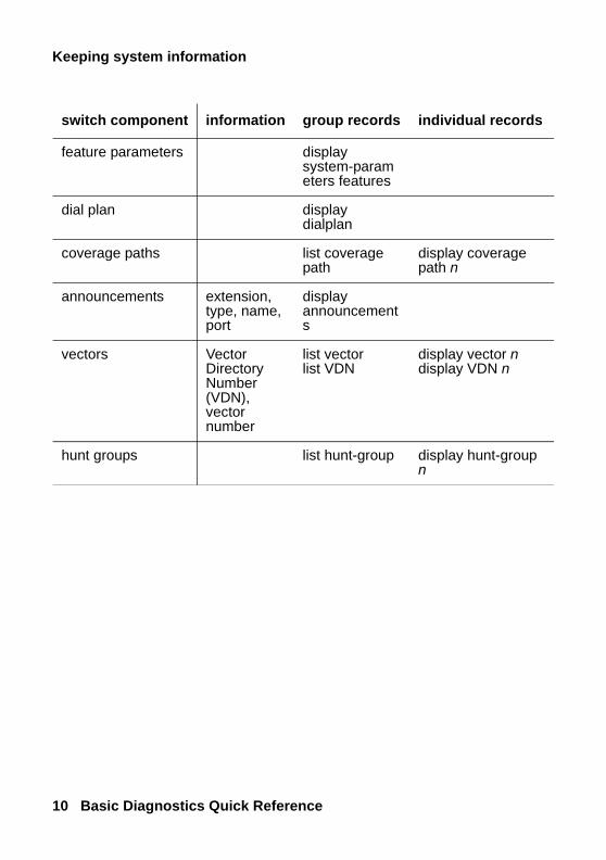
Keep track of the equipment and settings listed in the following table. Use the commands in the table to access the appropriate screens.

Retrieving baseline information
Issue 3 February 2007 9
info
rmat
ion
switch component information group records individual records
switch configuration the features your company purchased
display system parameters customer-options
switch capacity capacities enabled on your system
display capacity
cabinets and carriers
number of cabinets and carriers
list cabinet
circuit packs board type and vintage
list configuration all
display circuit-packs
trunks type of service
list trunk-group display trunk-group n
phones model number, extension number, name, location, cable, and jack
list stationlist extension-type
display station ndisplay extension n
class of restriction (COR)
calling privileges
list cor display cor n
class of service (COS)
display cos
feature access codes
display feature-access-codes
Keeping system information
10 Basic Diagnostics Quick Reference
feature parameters display system-parameters features
dial plan display dialplan
coverage paths list coverage path
display coverage path n
announcements extension, type, name, port
display announcements
vectors Vector Directory Number (VDN), vector number
list vector list VDN
display vector ndisplay VDN n
hunt groups list hunt-group display hunt-group n
switch component information group records individual records

Securing backups
Issue 3 February 2007 11
info
rmat
ion
Securing backups Backup your system regularly to keep your records up to date.
● Use save translations to backup changes to your system.
● Use save announcements to backup changes to announcements.
To verify that a backup was successful, review the Command Completion Status field.
● If the status field says Success, then the backup of the translations or the announcements was successful.
● If the status field does not say Success, record the Error Code and use the following list to determine what happened:
- 1 = unable to save to active-spe device
- 2 = unable to save to standby-spe device
Note:Note: For more information on performing backups, see the Avaya
Communication Manager Basic Administration Quick Reference.

Keeping system information
12 Basic Diagnostics Quick Reference
Problem solving strategies
Issue 3 February 2007 13
stat
us
2: Checking system status
This section explains how to use system information to keep track of the general health and status of your system. It tells you how to access system-wide and individual information, and describes how to check when changes are made to your system.
Problem solving strategies As an administrator, one of your responsibilities is to check the status of your system to determine whether it is performing properly. This is a proactive approach to system diagnostics.
● Use the status command to check on the operation of your system. See Viewing the system status on page 14 for more information.
● Use display alarms and display errors to closely monitor your system. See Alarms and errors on page 31 for more information.
Another of your responsibilities is to respond to reports of telephone problems from your users. You generally have to use a reactive approach to system diagnostics to perform this important function. See Solving common problems on page 19 for more information.
Checking system status
14 Basic Diagnostics Quick Reference
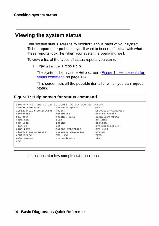
Viewing the system status Use system status screens to monitor various parts of your system. To be prepared for problems, you’ll want to become familiar with what these reports look like when your system is operating well.
To view a list of the types of status reports you can run:
1. Type status. Press Help.
The system displays the Help screen (Figure 1: Help screen for status command on page 14).
This screen lists all the possible items for which you can request status.
Figure 1: Help screen for status command
Let us look at a few sample status screens.
Please enter one of the following object command words:access-endpoint hardware-group psaadministered-connection health processor-channelsattendant interface remote-accessbri-port journal-link signaling-groupcard-mem link sp-linkcdr-link logins stationclan-ip mst synchronizationclan-port packet-interface sys-linkcleared-alarm-notif periodic-scheduled systemconference pms-link trunkdata-module pri-endpoint ttiesm

Problem solving strategies
Issue 3 February 2007 15
stat
us
Viewing general system operations Use the Status Health screen to determine whether everything is operating smoothly and to see a summary of your system status. You can use this report to look at alarms, see if anything is busied out, or check for any major problems.
To view the Status Health screen:
1. Type status health. Press Enter.The system displays the Status Health screen (Figure 2: Status health screen on page 15).
Figure 2: Status health screen
Viewing the status of a station Use status station to view the setup of each individual station. This command is often the first place to gather information when a user reports a problem with a telephone.For example, if a user tells you that the telephone rings a short ring and the call goes directly to coverage, use status station to see if send all calls (SAC) is activated on the user’s extension.
_______: status health (page 1) 2/26/2002 2:27:15 PM
SPE: B/auto A/functional OCC:St: 2% Sm: 23% Cp: 1% Idl: 74%PNC: B-PNC/auto A-PNC/functional ALARMS:Maj: 16 Min: 3 Wrn: 505Pwr: comm Sync:primary Logins:5 BUSYOUT:Trk: 0 Stn: 0 Oth: 0
Cab EmTr Maj Min Wrn PNC Cab EmTr Maj Min Wrn PNC1 auto- 0 1 57 up __ _____ ___ ___ ___ ___2 auto- 0 0 51 up __ _____ ___ ___ ___ ___3 auto- 16 1 54 up __ _____ ___ ___ ___ ___4 auto- 0 1 103 up __ _____ ___ ___ ___ ___5 auto- 0 0 240 up __ _____ ___ ___ ___ ___
Checking system status
16 Basic Diagnostics Quick Reference
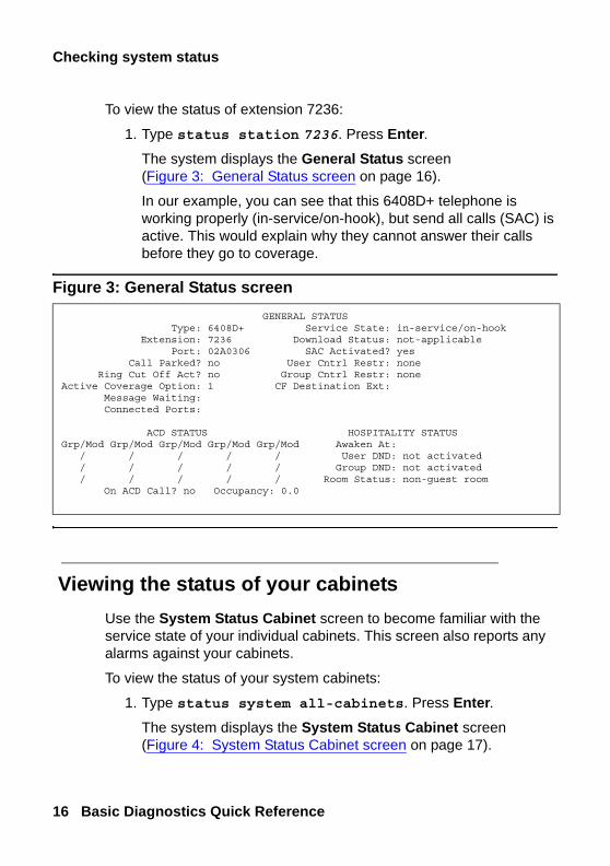
To view the status of extension 7236:
1. Type status station 7236. Press Enter.The system displays the General Status screen (Figure 3: General Status screen on page 16).
In our example, you can see that this 6408D+ telephone is working properly (in-service/on-hook), but send all calls (SAC) is active. This would explain why they cannot answer their calls before they go to coverage.
Figure 3: General Status screen
Viewing the status of your cabinets Use the System Status Cabinet screen to become familiar with the service state of your individual cabinets. This screen also reports any alarms against your cabinets.
To view the status of your system cabinets:
1. Type status system all-cabinets. Press Enter.The system displays the System Status Cabinet screen (Figure 4: System Status Cabinet screen on page 17).
GENERAL STATUS Type: 6408D+ Service State: in-service/on-hook Extension: 7236 Download Status: not-applicable Port: 02A0306 SAC Activated? yes Call Parked? no User Cntrl Restr: none Ring Cut Off Act? no Group Cntrl Restr: noneActive Coverage Option: 1 CF Destination Ext: Message Waiting: Connected Ports:
ACD STATUS HOSPITALITY STATUSGrp/Mod Grp/Mod Grp/Mod Grp/Mod Grp/Mod Awaken At: / / / / / User DND: not activated / / / / / Group DND: not activated / / / / / Room Status: non-guest room On ACD Call? no Occupancy: 0.0

How can Avaya help?
Issue 3 February 2007 17
stat
us
Figure 4: System Status Cabinet screen
Using a number of the status commands can go a long way in helping you know if your system is running OK.
How can Avaya help?With an Avaya Service Agreement or warranty coverage, your system running Communication Manager is linked to Avaya Expert Systems for constant remote monitoring, proactive diagnosis and trouble resolution. This electronic monitoring is so effective that 70% of all troubles are remotely identified, diagnosed, and resolved. This round-the-clock coverage is the best in the industry, helping to provide maximum up-time for your voice communication system.Also, Avaya is the first in the industry to provide Power Surge Protection, completely covering the costs of product damage due to power surges. You are automatically covered if your system is under Warranty or Service Agreement, and power protection has been installed, all local and national electrical codes have been followed, and Avaya site requirements have been met. Service Agreement and warranty customers will receive first priority toward resolution of these problems.
SYSTEM STATUS CABINET 1SELECT SPE ALARMS TONE/ SERVICE SYSTEM SYSTEM
SPE MODE SWITCH MAJOR MINOR CLOCK STATE CLOCK TONE1A standby auto 0 0 1A in standby standby1B active spe b 0 0 1B in active active SERVICE CONTROL DEDICATED SERVICE BUS ALARMS BUS OPEN BUSTDM STATE CHANNEL TONES PKT STATE MAJOR MINOR FAULTS LEADS1A in n n1B in y y 1 in n n 0 0
EMERGENCY SELECT SERVICE CABINETTRANSFER SWITCH EXP-LINK STATE MODE TYPE1A on 01A01-02A01 in active MCC1B auto-off 01B01-02B02 in standby

Checking system status
18 Basic Diagnostics Quick Reference
Diagnosing a problem
Issue 3 February 2007 19
pro
ble
m s
olv
ing
3: Solving common problems
This section tells you the questions to ask and the information to gather to solve some of the most basic telephone problems. It also describes how to solve common call-center problems.
Diagnosing a problem As a system administrator, an important part of your job is to respond to trouble calls from users. You can identify some of the most common of these problems by following a few simple steps, asking the right questions, and trying to recreate the problem.Use a set of questions to determine if:
● the equipment or process has worked before and is now broken, or if this is a new set-up that you need to correct
● the problem comes from your company’s own equipment, or if the problem comes from your vendor
● the problem originates within your system, or if the source of the problem is outside of your own facility

Solving common problems
20 Basic Diagnostics Quick Reference
Ask the following basic questions of yourself, your users, and other system administrators who work with you:
● Is this a new feature or piece of equipment, or did it work before but does not work now?
● Does the trouble arise when dialing outside the system, dialing into the system, or dialing inside the system?
● Can we duplicate the problem?
Solving common telephone problems This section describes the approach that many administrators take to diagnose and correct common problems with telephones. Following is a list of suggested actions you can take if you have a problem.
● ask for the exact symptoms
● try to duplicate the problem or have the user show you the problem
● look at the telephone
● find out if the telephone was swapped out
● check the physical connections (for example, see if the telephone is plugged in)
● check that the telephone is where it is supposed to be
● try the telephone at another location
● ask if the cord or handset was changed
● check status station
● use display station to look at the station screens page-by-page
● check the station screens for SAC, coverage paths
● look at printed system records for discrepancies
Solving common telephone problems
Issue 3 February 2007 21
pro
ble
m s
olv
ing
● check the alarms and errors logs
● clear any alarms and errors
● test the circuit packs
Let’s take a look at the types of problems users report to their system administrators, and see how to diagnose and correct the problem.
The user cannot dial out A user calls to report that the telephone “does not work.” Ask questions to find out what is really wrong so you can know how to fix the problem.To find out why a telephone does not work, ask these questions:
● Does the problem occur when:
- they try to answer a ringing incoming call
- they try to make a call
● If the problem occurs when they try to make a call, is the call
- internal, station to station
- external, to an outside telephone
● Is the problem with just one number, or are they unable to place any outgoing calls?
● Is this a new telephone, or is this a new problem with an existing telephone (were they able to call out before)
● Do they hear dial tone before they try to call?
● What do they hear after they dial?
- a tone of some kind
- a message
- static
- nothing
Solving common problems
22 Basic Diagnostics Quick Reference
● If they hear a message after they dial, what is the exact message?
If the message says that the call cannot be completed as dialed, the problem is likely your ARS programming. For more information on changing your outbound routing, see the Avaya Communication Manager Basic Administration Quick Reference.
Incoming calls ring but do not reach the user Another user calls to report that his telephone “does not work.” Ask questions similar to the ones listed above. You determine that the user can call out, and that the telephone rings but there is no call on the line when the user picks up.Type status station to see if Send All Calls (SAC) is activated.
The message lamp does not go out This problem often occurs even when the messages associated with the telephone have been cleared.
To clear a message waiting light:
1. Type clear amw all n, where n is the extension. Press Enter.

Solving common telephone problems
Issue 3 February 2007 23
pro
ble
m s
olv
ing
Diagnosing general trunk problems The following questions help you determine a problem with a trunk.
● Is the trouble on every call or is the trouble intermittent?
● Are you getting any sort of recordings when you try to dial out on this trunk?
● Can you identify the trunk in question?
Use a trunk access code (tac) to identify the trunk, especially if the console has a trunk ID button.
● Is there static on the call?
This is likely a problem with the trunk external to the system.
● Have you notified your vendor of this problem?
Diagnosing tie trunk problems The following questions help you determine a problem with a tie trunk.
● Is the problem on incoming calls only?
● Is the problem on outgoing calls only?
● What happens when you try to use this trunk?
● Have you notified the T1 vendor?
● Does this trunk connect to another location?
If so, try to determine the IL number of that location.
● Do you know the circuit ID of this trunk?

Solving common problems
24 Basic Diagnostics Quick Reference
Diagnosing modem problems The following questions help you determine a problem with a modem.
● What is the extension of the modem?
● Is the modem connected through the system?
● What is the modem connected to?
For example, computer, fax, or CMS?
● Have the setup options been changed or checked recently?
● What company manufactures the modem?
● What is the model number?
Diagnosing printer troubles The following questions help you determine a problem with a printer.
● What is the problem with the printer?
● What is the printer used for?
For example, is it connected to the system, CMS, CAS, or maybe AUDIX?
● Who manufactures the printer?
● What is the model number?
Solving call center problems
Issue 3 February 2007 25
pro
ble
m s
olv
ing
Diagnosing password, login, andterminal access problems
If the problem is with remote dial-in access, ask:
● How do you dial in?
● What type of software or dialing program do you use?
● What error messages do you see when you try to dial in?
If your password expired, is not working, or is incorrect, call Avaya for assistance in getting the issue resolved.
Diagnosing SAT problems If the problem is with the System Access Terminal (SAT), ask:
● What type of terminal is it?
● What type of trouble are you having?
Solving call center problems This section helps you identify and solve common problems affecting hunt groups, splits, announcements, and caller access.The tables below describe symptoms and solutions for common problems in call centers not using ACD or call vectoring.

Solving common problems
26 Basic Diagnostics Quick Reference
Cannot record an announcement onIntegrated Announcement Boards
Possible Causes Solutions
You do not get port 0 when you start to record an announcement.
If port 0 is in use when you start to record an announcement, you hear a reorder (or fast-busy) tone followed by silence. Redial the announcement access code and extension every 45 seconds until your recording session is successful.
The telephone you are using to record the announcement does not have a COS with console permission.
Use the Station screen to change the COS for that telephone to a different COS that has console permissions.
The Pr (protected) field on the Announcements/Audio Sources screen is y.
Set this field to n to allow changes from a telephone with console permissions.
The proper procedure was not used.
Try again. Verify the Feature Access Code (FAC) you’re using.
The extension you want to use is not assigned to an announcement.
Check the number you’re dialing, or assign the extension to an announcement on the Announcements/audio Sources screen.
Solving call center problems
Issue 3 February 2007 27
pro
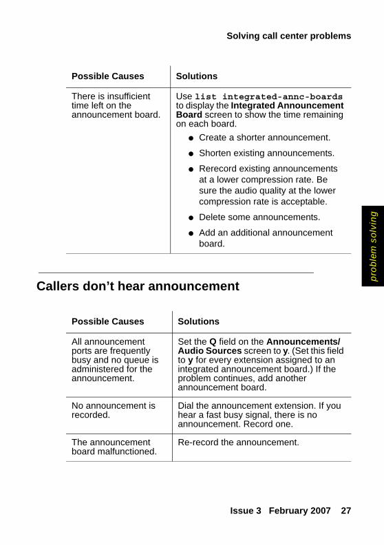
ble
m s
olv
ing
Callers don’t hear announcement
There is insufficient time left on the announcement board.
Use list integrated-annc-boards to display the Integrated Announcement Board screen to show the time remaining on each board.
● Create a shorter announcement.
● Shorten existing announcements.
● Rerecord existing announcements at a lower compression rate. Be sure the audio quality at the lower compression rate is acceptable.
● Delete some announcements.
● Add an additional announcement board.
Possible Causes Solutions
Possible Causes Solutions
All announcement ports are frequently busy and no queue is administered for the announcement.
Set the Q field on the Announcements/Audio Sources screen to y. (Set this field to y for every extension assigned to an integrated announcement board.) If the problem continues, add another announcement board.
No announcement is recorded.
Dial the announcement extension. If you hear a fast busy signal, there is no announcement. Record one.
The announcement board malfunctioned.
Re-record the announcement.

Solving common problems
28 Basic Diagnostics Quick Reference
A device in an Auto Answer hunt group does not respond
Too many abandoned calls
Possible Causes Solutions
The device is off or malfunctioning.
With UCD-MIA, since a malfunctioning unit will be the most idle port all calls to the hunt group may begin to go to the malfunctioning device.
1. Dial each modem’s extension until you find the one that isn’t answering.
2. Busy out that device, or remove its extension number from the Hunt Group screen until the device can be fixed.
Possible Causes Solutions
There is no coverage path.
Assign a coverage point in the Coverage Path field on the Hunt Group screen.
Announcements are not being used or need to be changed.
Create announcements that encourage callers to wait. Tell callers their call is very important and ask them to stay on the line.
Customers aren’t willing to wait until the call is answered.
Add agents to reduce average speed of answer.

Solving call center problems
Issue 3 February 2007 29
pro
ble
m s
olv
ing
Customers complain they get a busy signal
Possible Causes Solutions
Trunk capacity is insufficient.
Check the system Trunk Summary report, including yesterday-peak, today-peak and last hour. Print last-hour once an hour during business hours.Check the % ATB (All Trunks Busy) field for both incoming and two-way trunks. If this figure is consistently high for ONE-WAY incoming trunks, calls are probably being blocked. Add trunks.If ARS is being used on a two-way trunk, it may need further investigation.Communication Manager can’t tell you if calls are being blocked in the central office. Ask your network provider to do a traffic study on incoming calls.
The administered queue length is too short.
Set the Queue Length field on the Hunt Group screen to a value equal to or greater than the number of hunt group agents. Add more agents.
There’s no coverage path.
Assign a coverage point in the Coverage Path field on the Hunt Group screen.

Solving common problems
30 Basic Diagnostics Quick Reference

Maintenance reports
Issue 3 February 2007 31
alar
ms
/ err
ors
4: Alarms and errors
This section is for adventurous administrators who are curious about how to diagnose and fix common problems. The information here will help you understand how to read and interpret:
● error logs
● alarm logs
Maintenance reportsAvaya Communication Manager monitors many system components. When a component fails or performs unacceptably, the subsystem generates two kinds of reports:
● detailed reports in the error log
● general reports in the alarm log
The system detects error conditions in its components through Maintenance Objects (MO). MOs are the software modules that monitor, test, and report possible fault conditions.
Viewing error logs
It is a good idea to run and inspect error logs on a regular basis. You can view all active system errors on the error log. You can also specify a particular component of your system or a certain time period to be reported on the error log.

Alarms and errors
32 Basic Diagnostics Quick Reference
To view the error log:
1. Type display errors. Press Enter.The system displays the Error Report screen (Figure 5: Error Report screen on page 32).
Figure 5: Error Report screen
2. Perform one of the following options:
- To see all current errors, press Enter.- To see particular errors, indicate the errors that you want to
see by entering the information requested in each field. (See the field descriptions listed in the following section.) Press Enter.The system displays the Hardware Error Report screen (Figure 6: Hardware Error Report on page 34).
ERROR REPORTThe following options control which errors will be displayed.
ERROR TYPESError Type: Error List: active-alarmsREPORT PERIODInterval: a From: / / : To: / / :EQUIPMENT TYPE ( Choose only one, if any, of the following )
Cabinet:Port Network:Board Number:
Port:Category:
Extension:Trunk ( group/member ): /

Maintenance reports
Issue 3 February 2007 33
alar
ms
/ err
ors
Error report field descriptions
Field What to enter
Error Type
error type
Error List
active-alarms, errors, or cleared-errors
Interval h(our), d(ay), w(eek), m(onth), a(ll)
From/To time interval by date and time
Cabinet cabinet number (1 - 44)
Port Network
port network number (1 - 44)
Board Number
5-character board number in UUCSS format:UU = cabinet (1-44), C = carrier (A-E), SS = slot (0-20)
Port 7-character port address in UUCSSss format:UU = cabinet (1-44), C = carrier (A-E), SS = slot (0-20), ss = circuit
Category category name (choose from the list below):
adm-conn announce bri/asai cdr data-mod
detector dup-spe environ exp-intf ext-dev
generatr inads-link infc maint mass-st
mbus memory misc mmi mnt-test
modem mssnet pkt pms/jrnl pnc
pncmaint pnc-peer procr quick-st s-syn
spe stabd stacrk stations sys-link
Alarms and errors
34 Basic Diagnostics Quick Reference
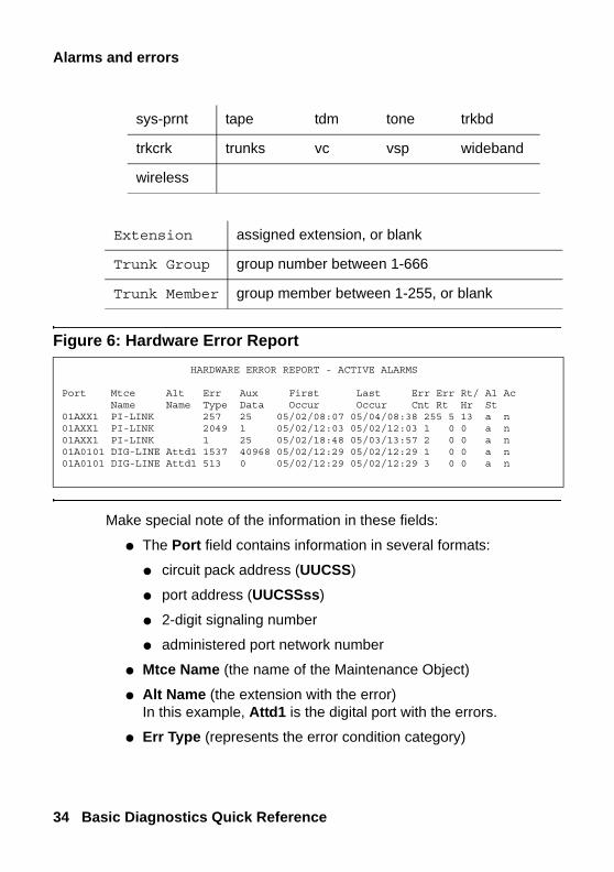
Figure 6: Hardware Error Report
Make special note of the information in these fields:
● The Port field contains information in several formats:
● circuit pack address (UUCSS)
● port address (UUCSSss)
● 2-digit signaling number
● administered port network number
● Mtce Name (the name of the Maintenance Object)
● Alt Name (the extension with the error)In this example, Attd1 is the digital port with the errors.
● Err Type (represents the error condition category)
sys-prnt tape tdm tone trkbd
trkcrk trunks vc vsp wideband
wireless
Extension assigned extension, or blank
Trunk Group group number between 1-666
Trunk Member group member between 1-255, or blank
HARDWARE ERROR REPORT - ACTIVE ALARMS
Port Mtce Alt Err Aux First Last Err Err Rt/ Al AcName Name Type Data Occur Occur Cnt Rt Hr St
01AXX1 PI-LINK 257 25 05/02/08:07 05/04/08:38 255 5 13 a n01AXX1 PI-LINK 2049 1 05/02/12:03 05/02/12:03 1 0 0 a n01AXX1 PI-LINK 1 25 05/02/18:48 05/03/13:57 2 0 0 a n01A0101 DIG-LINE Attd1 1537 40968 05/02/12:29 05/02/12:29 1 0 0 a n01A0101 DIG-LINE Attd1 513 0 05/02/12:29 05/02/12:29 3 0 0 a n

Maintenance reports
Issue 3 February 2007 35
alar
ms
/ err
ors
● Aux Data (represents a detail of the Error Type)
● First Occur (indicates the date/time of the first occurrence)
● Last Occur (indicates the date/time of the last occurrence)
● Err Cnt (lists how many occurrences since the first one)
Interpreting the error log
The Hardware Error Report in our example shows five error entries. The system detected an unplugged digital telephone. Here is how to interpret the report:
● PI-LINK is the MO monitoring the processor interface links to digital equipment, including adjuncts. You can see that over 2 days (May 2 to May 4) it incurred 255 type-257 errors, 1 type-2049 error, and 2 type-1 errors.
● The DIG-LINE errors indicate that the system can’t find the telephone administered to port 01A0101. According to the system, that is supposed to be attendant 1 (Alt Name).
Notice that the Err Type and Aux Data fields for both MOs contain many different numbers. The numbers are software codes that represent a specific error condition.
Clearing the error
If an important component in your system fails, the software records that “event” with code numbers in the error or alarm log.
To interpret the error codes and clear the error:
1. Look up the MO (for example, DIG-LINE or PI-LINK) in the Communication Manager maintenance books for your system.
2. Find the error type in the Hardware Error Type table for that MO.
3. Find the note associated with that error type for an explanation of the conditions that generated the error.

Alarms and errors
36 Basic Diagnostics Quick Reference
4. Perform the recommended procedure to clear the error.
The recommended procedure may require you to test alarmed components. Be sure to have test permissions enabled.
If any tests fail or abort, you will get an error code for the test.
5. Look up the test error code by MO in your Communication Manager maintenance books.
6. Find the numbered test listed in the test results.
7. Look for the correct combination of error code and test result in the numbered-test tables.
Alarm logs Alarms are classified as major, minor, or warning, depending the degree of severity and the effect on the system.
warning level and description
reported to INADS?
reported toconsole?
take this action
majorCritical service degradation
Y Y(occurs after 4 attempts to call INADS)
Immediate attention
minorSome service degradation, but system is operable, usually limited to a few trunks or stations or a single feature.
Y Y(occurs after 4 attempts to call INADS)
Check to see what service is affected

Maintenance reports
Issue 3 February 2007 37
alar
ms
/ err
ors
Alarms are further classified as:
● on-board problems originate within the circuitry of the alarmed circuit pack
● off-board problems originate in a process or component that is external to the circuit pack
Reading the alarm log
Let’s look at an alarm log that results from an unplugged digital telephone.
To the view the alarm log:
1. Type display alarms. Press Enter.The system displays the Alarm Report screen (Figure 7: Alarm Report screen on page 38).
warningFailure that causes no significant service degradationNote: DS1 off board faults (error type 138) generate warning alarms only, indicating a customer network problem. In this case, warning alarms can cause critical service degradation.
N(INADS can receive some downgraded warning alarms)
N Monitor the situation; check for service or equipment interruption or failure outside the system.
warning level and description
reported to INADS?
reported toconsole?
take this action

Alarms and errors
38 Basic Diagnostics Quick Reference
Figure 7: Alarm Report screen
2. Indicate which alarms you want to view by entering y and Enter after each alarm type.
Note:Note: Unless you can restrict the trouble to a particular time
period, press Enter to see all active alarms.
If you choose n for major alarms and y for minor and warning alarms, you will not see the high-level information that you may need to determine what is wrong with your system.
3. Press Enter to view the alarm report.
4. The system displays the Alarm Report detail screen (Figure 8: Alarm Report screen on page 39).
ALARM REPORT The following options control which alarms will be displayed. ALARM TYPES
Active? y Resolved? nMajor? y Minor? y Warning? y
REPORT PERIODInterval: m From: / / : To: / / :
EQUIPMENT TYPE ( Choose only one, if any, of the following ) Cabinet: Port Network: Board Number: Port: Category: Extension: Trunk ( group/member ): /

Maintenance reports
Issue 3 February 2007 39
alar
ms
/ err
ors
Figure 8: Alarm Report screen
Interpreting alarm logs
The Alarm Report lists the major alarms first, followed by the minor and warning alarms.The alarm log in the example above shows:
● a processor interface link (PI-LINK) at address 01AXX1 has alarmed three times on May 2 with off-board (On Brd? = n) warnings.
● the same port (01A0101) on a digital line (DIG-LINE) circuit pack has alarmed twice on May 2 in response to two different error counters (refer to the error log example).
Clearing alarm logs To clear an alarm log:
1. Investigate or fix the first major alarm in the log.
2. See if other alarms are retired by fixing the most severe problem first.
ALARM REPORT
Port Maintenance On Alt Alarm Svc Ack? Date DateName Brd? Name Type State 1 2 Alarmed Resolved
01AXX1 PI-LINK n WARNING 05/02/09:48 00/00/00:0001AXX1 PI-LINK n WARNING 05/02/09:48 00/00/00:0001A0101 DIG-LINE n Attd1 WARNING RDY 05/02/12:29 00/00/00:0001A0101 DIG-LINE n Attd1 WARNING RDY 05/02/12:29 00/00/00:0001AXX1 PI-LINK n WARNING 05/02/18:49 00/00/00:00

Alarms and errors
40 Basic Diagnostics Quick Reference
Assigning alarm buttons You can administer feature button lamps on any telephone to act as alarm indicators, similar to the alarm lamp on the attendant console. The following table describes the meaning of the green light associated with an alarm button.
Press the alarm button to turn off the light. The light flashes again if the alarm is still active when the next maintenance routine runs.
Understanding common error types This section discusses frequently-encountered error types, and explains why they occur.
Error type 18, busied out Error type 18 is a reminder from the system that a component has been busied out. The busyout command is used to temporarily disable a component and is usually used before you test or replace a component.Use the release command (permissions enabled) to restore a component to its normal operating mode.
status of light meaning
flashing green an alarm occurs
steady green INADS notified and acknowledges alarm
light goes off an alarm is resolved

Understanding common error types
Issue 3 February 2007 41
alar
ms
/ err
ors
For example, you receive a complaint that a telephone does not work. As part of your diagnosis, you:
● use status station
OR
● view the hardware error report for error 18
To view a hardware error report for error 18:
1. Type display errors. Press Enter.The system displays the Hardware Error Report screen.
2. Fill in the Err Type field. Press Enter.In our example, type 18.
The system displays the Hardware Error Report for error 18 (Figure 9: Hardware Error Report on page 41).
Figure 9: Hardware Error Report
The log entry indicates that extension 1234, a digital line, is busied out (ERR TYPE 18).
Use the release command (permissions enabled) to remove the busyout status from the station. In our example:
1. Type release port 01A0901 (permissions enabled). Press Enter.The station is no longer busied-out.
HARDWARE ERROR REPORT - ACTIVE ALARMS Port Mtce Alt Err Aux First Last Err Err Rt/ Al Ac
Name Name Type Data Occur Occur Cnt Rt Hr St
01A0901 DIG-LINE 1234 18 03/09/00:30 03/09/00:30 1 0 0 a n

Alarms and errors
42 Basic Diagnostics Quick Reference
Error type 513, equipment missing Error type 513 notifies you that equipment, such as telephones, data modules, or circuit packs, are administered but not physically connected to the system.
For example, view a hardware error report for error 513:
1. Type display errors. Press Enter.The system displays the Hardware Error Report screen.
2. Fill in the Err Type field. Press Enter.In our example, type 513.
The system displays the Hardware Error Report for error 513 (Figure 10: Hardware Error Report on page 42).
Figure 10: Hardware Error Report
In this example, a digital telephone is missing. A port on the digital line circuit pack (DIG-LINE) at cabinet 1, carrier C, slot 05, port 07 does not have its administered equipment physically present (Err Type 513).
To fix error 513 in our example:
1. Plug the telephone into the jack assigned to port 01C0507.
2. Type test station 7157 (permissions enabled). Press Enter to test the telephone.
The system will clear the error only after the system runs its administered checks and diagnostics.
HARDWARE ERROR REPORT - ACTIVE ALARMS Port Mtce Alt Err Aux First Last Err Err Rt/ Al Ac
Name Name Type Data Occur Occur Cnt Rt Hr St
01C0507 DIG-LINE 7157 513 0 03/09/00:30 03/09/00:30 1 0 0 a n
Preventing alarms and errors
Issue 3 February 2007 43
alar
ms
/ err
ors
Error type 1, circuit pack removed Error type 1 often indicates that an administered circuit pack has been removed.
To correct the problem and clear Error type 1:
1. Replace and latch the circuit pack in its administered slot.
The next time the system runs its routine maintenance program, it should be able to “see” the circuit pack and the error will not appear.
Preventing alarms and errors This section lists a few common causes of unnecessary alarms.
Turn off maintenance The Remote Loop-Around Test sends a burst of current to activate a telephone’s ringer. If the ringer responds, the test detects the return. Data modules, fax machines and modems do not have ringers and do not respond to this test. This generates an error on that port.You should turn off this test for data modules, fax machines and modems. Turning off the test does not affect the performance of any of these devices.
To turn off the maintenance test:
1. Type change data-module n, where n is the extension number. Press Enter.The system displays the Data Module screen (Figure 11: Data Module screen on page 44).

Alarms and errors
44 Basic Diagnostics Quick Reference
Figure 11: Data Module screen
2. Change the Remote Loop-Around Test field to n.
3. Press Enter to save your changes.
Remove unused circuit packs Occasionally, a company upgrades telephones from analog models to digital telephones. The upgrade process is to:
1. Remove the analog line and trunk administration
2. Remove the old analog equipment
3. Rewire the workplace for the new digital telephones and jacks
4. Administer the new digital telephones and circuit packs
If the analog circuit packs remain physically plugged into the system and are still administered as circuit packs (even though the administration is removed in Step 1 above), the system generates errors. This stops when you remove the administration (change circuit-pack UUCSS) for this unused circuit pack.
DATA MODULEData Extension: 3151 Name: joes r2cms pdm BCC: 2
Type: pdm COS: 1 Remote Loop-Around Test? nPort: 01C0501 COR: 1 Secondary data module? nITC: restricted TN: 1 Connected to: dte
ABBREVIATED DIALING List1: SPECIAL DIALING OPTION: ASSIGNED MEMBER (Station with a data extension button for this data module ) Ext Name 1:
Preventing alarms and errors
Issue 3 February 2007 45
alar
ms
/ err
ors
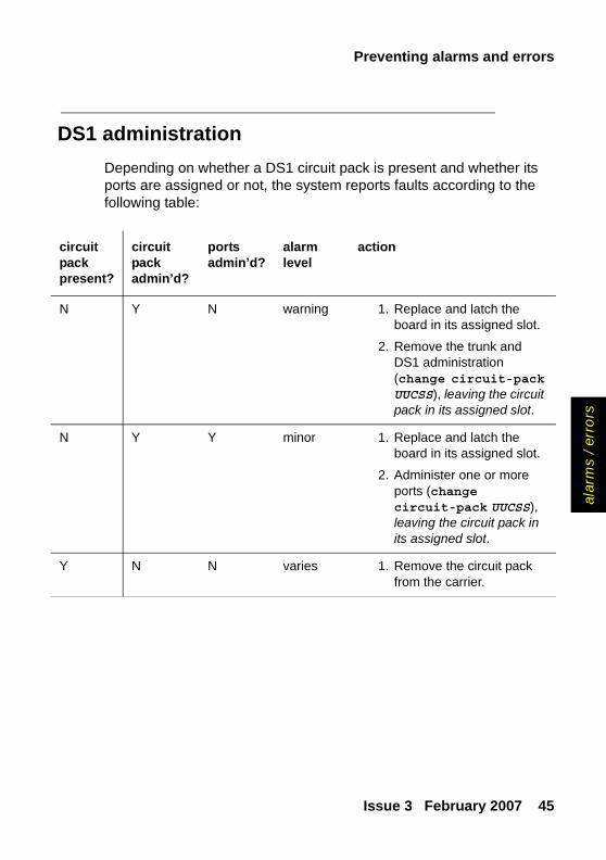
DS1 administration Depending on whether a DS1 circuit pack is present and whether its ports are assigned or not, the system reports faults according to the following table:
circuitpackpresent?
circuitpackadmin’d?
portsadmin’d?
alarmlevel
action
N Y N warning 1. Replace and latch the board in its assigned slot.
2. Remove the trunk and DS1 administration (change circuit-pack UUCSS), leaving the circuit pack in its assigned slot.
N Y Y minor 1. Replace and latch the board in its assigned slot.
2. Administer one or more ports (change circuit-pack UUCSS), leaving the circuit pack in its assigned slot.
Y N N varies 1. Remove the circuit pack from the carrier.

Alarms and errors
46 Basic Diagnostics Quick Reference

Troubleshooting
Issue 3 February 2007 47
feat
ure
s
5: Using features to troubleshoot
TroubleshootingYou can use some Avaya Communication Manager features to help you identify if your system is having problems or to help you diagnose problems you know are occurring. The table below shows you which features to use for various kinds of system problems.
feature problem area
trunks phones huntgroups
paginggroups
Automatic Circuit Assurance
X
Busy Verify X X X
Facility Busy Indication X X X
Facility Test Calls X X
Trunk Identification X

Using features to troubleshoot
48 Basic Diagnostics Quick Reference
Automatic Circuit Assurance You can use Automatic Circuit Assurance (ACA) to help identify faulty trunks. If activated, your system notifies you with a referral call when it detects unusual trunk usage like very short or very long calls. It needs to be turned on for each individual trunk group.
The referral call arrives on an idle call appearance. If you answer the call, your display shows:
● that the call is an ACA call
● the trunk-group access code
● the trunk-group member number
● the reason for the call (short or long holding time)
To use ACA on a G3V2 or older system1. Assign an ACA button to your telephone.
2. Press the ACA button to activate your telephone for referrals.
3. When you receive an ACA referral call, answer the call.
4. Record the information listed on your display to use for further troubleshooting.
To use ACA on a G3V3 or newer system1. Assign an ACA-Halt button to your telephone.
2. Leave the ACA-Halt button OFF to keep your telephone active for referrals.
3. When you receive an ACA referral call, answer the call.
4. Record the information listed on your display to use for further troubleshooting.
Troubleshooting
Issue 3 February 2007 49
feat
ure
s
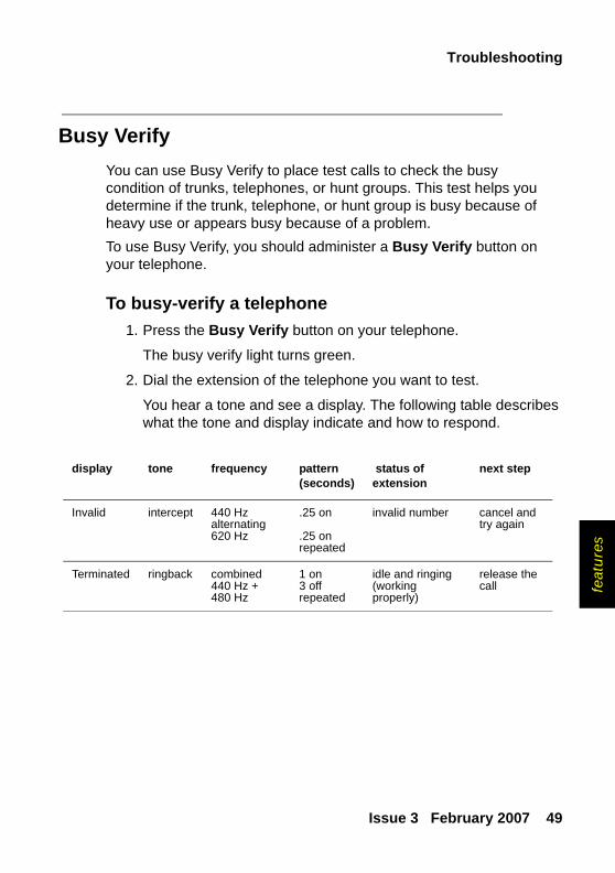
Busy Verify You can use Busy Verify to place test calls to check the busy condition of trunks, telephones, or hunt groups. This test helps you determine if the trunk, telephone, or hunt group is busy because of heavy use or appears busy because of a problem.To use Busy Verify, you should administer a Busy Verify button on your telephone.
To busy-verify a telephone1. Press the Busy Verify button on your telephone.
The busy verify light turns green.
2. Dial the extension of the telephone you want to test.
You hear a tone and see a display. The following table describes what the tone and display indicate and how to respond.
display tone frequency pattern(seconds)
status of extension
next step
Invalid intercept 440 Hzalternating620 Hz
.25 on
.25 onrepeated
invalid number cancel and try again
Terminated ringback combined440 Hz +480 Hz
1 on3 offrepeated
idle and ringing (working properly)
release the call
Using features to troubleshoot
50 Basic Diagnostics Quick Reference
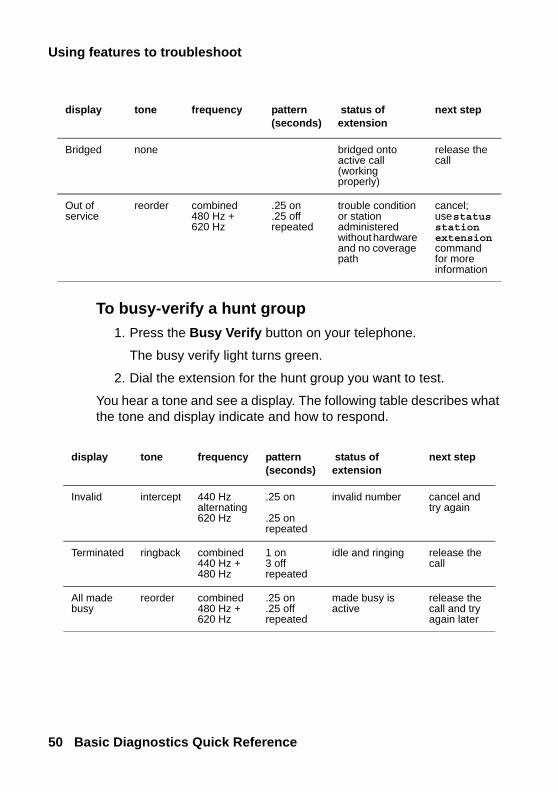
To busy-verify a hunt group 1. Press the Busy Verify button on your telephone.
The busy verify light turns green.
2. Dial the extension for the hunt group you want to test.
You hear a tone and see a display. The following table describes what the tone and display indicate and how to respond.
Bridged none bridged onto active call (working properly)
release the call
Out of service
reorder combined480 Hz +620 Hz
.25 on
.25 offrepeated
trouble condition or station administered without hardware and no coverage path
cancel;use status station extensioncommand for more information
display tone frequency pattern(seconds)
status of extension
next step
display tone frequency pattern(seconds)
status of extension
next step
Invalid intercept 440 Hzalternating620 Hz
.25 on
.25 onrepeated
invalid number cancel and try again
Terminated ringback combined440 Hz +480 Hz
1 on3 offrepeated
idle and ringing release the call
All made busy
reorder combined480 Hz +620 Hz
.25 on
.25 offrepeated
made busy is active
release the call and try again later

Troubleshooting
Issue 3 February 2007 51
feat
ure
s
To busy-verify a trunk 1. Press the Busy Verify button on your telephone.
The busy verify light turns green.
2. Dial the trunk access code for the trunk you want to test.
Your display should be blank and you should hear dial tone. If your display shows “DENIED” and you hear intercept tone, repeat steps 1 and 2.
If you have trunk group select buttons on your telephone, you can also press the Busy Verify button and then press the Trunk Group Select button for the appropriate trunk.
3. Dial the trunk-group member number you want to verify.
You hear a tone and see a display. The following table describes what the tone and display indicate and how to respond.
Denied reorder same as above
same as above
active on a call release the call and try again later
Out of service
reorder same as above
same as above
trouble condition or station administered without hardware
cancel; report an out-of-service condition
display tone frequency pattern(seconds)
status of extension
next step
display tone frequency pattern(seconds)
status of extension
next step
Invalid intercept 440 Hzalternating620 Hz
.25 on
.25 on repeated
invalid cancel and try again
Verified confir-mation
idle and ringing (working properly)
release the call

Using features to troubleshoot
52 Basic Diagnostics Quick Reference
Facility Busy Indication You can use Facility Busy Indication to display the idle or busy condition of telephones, trunks, or paging zones.To use this feature you need to add facility busy indication buttons to your telephone. Label the facility busy buttons as “Busy” followed by the number or name of the facility being monitored.If the green light associated with the Facility Busy Indication button stays lit for a long time, the facility may have a problem.
none ringback combined440 Hz +480 Hz
1 s on3 s offrepeated
idle automatic or release link(working properly)
release the call
none dial tone combined350 Hz +440 Hz
continuous idle (working properly)
release the call
Bridged none bridged onto active call (working properly)
release the call
Out ofService
reorder combined480 Hz +620 Hz
.25 on
.25 offrepeated
trouble condition cancel; report an out-of-service condition
display tone frequency pattern(seconds)
status of extension
next step
Troubleshooting
Issue 3 February 2007 53
feat
ure
s
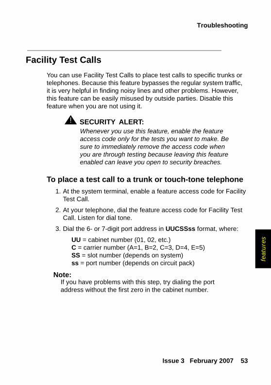
Facility Test Calls You can use Facility Test Calls to place test calls to specific trunks or telephones. Because this feature bypasses the regular system traffic, it is very helpful in finding noisy lines and other problems. However, this feature can be easily misused by outside parties. Disable this feature when you are not using it.
! SECURITY ALERT:SECURITY ALERT: Whenever you use this feature, enable the feature
access code only for the tests you want to make. Be sure to immediately remove the access code when you are through testing because leaving this feature enabled can leave you open to security breaches.
To place a test call to a trunk or touch-tone telephone1. At the system terminal, enable a feature access code for Facility
Test Call.
2. At your telephone, dial the feature access code for Facility Test Call. Listen for dial tone.
3. Dial the 6- or 7-digit port address in UUCSSss format, where:
UU = cabinet number (01, 02, etc.)C = carrier number (A=1, B=2, C=3, D=4, E=5)SS = slot number (depends on system)ss = port number (depends on circuit pack)
Note:Note: If you have problems with this step, try dialing the port
address without the first zero in the cabinet number.
Using features to troubleshoot
54 Basic Diagnostics Quick Reference
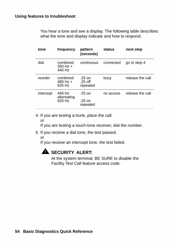
You hear a tone and see a display. The following table describes what the tone and display indicate and how to respond.
4. If you are testing a trunk, place the call.orIf you are testing a touch-tone receiver, dial the number.
5. If you receive a dial tone, the test passed.orIf you receive an intercept tone, the test failed.
! SECURITY ALERT:SECURITY ALERT: At the system terminal, BE SURE to disable the
Facility Test Call feature access code.
tone frequency pattern(seconds)
status next step
dial combined350 Hz +440 Hz
continuous connected go to step 4
reorder combined480 Hz +620 Hz
.25 on
.25 offrepeated
busy release the call
intercept 440 Hzalternating620 Hz
.25 on
.25 onrepeated
no access release the call
Troubleshooting
Issue 3 February 2007 55
feat
ure
s
Trunk Identification You can identify a faulty or noisy trunk with Trunk Identification. You can use Trunk Identification:
● on an active call
● while accessing a trunk
To identify the specific trunk used on a call:
1. Press the Trunk ID button.
Trunk access code and trunk group member number appears on the display.
If 2 trunks are used on the call, the identification of the last trunk added to the call displays. If more than 2 trunks are on a call, Trunk Identification is denied.
2. See if there are any on-board alarms against a trunk circuit pack.
If no, report the trunk problem to the appropriate vendor.
If yes, report the trunk problem and the identification information to Avaya.

Using features to troubleshoot
56 Basic Diagnostics Quick Reference

Solving Softphone problems
Issue 3 February 2007 57
IP &
H.3
23
6: Solving IP and H.323 problems
This section describes some basic troubleshooting tips and tools that may help you solve problems with IP (internet protocol) telephones, Softphones, and IP and H.323 trunk issues.In addition to using this section, you may want to refer to Administration for Network Connectivity for Avaya Communication Manager for basic IP administration.
Solving Softphone problems This section discusses some common problems you or your users may encounter while using IP Softphones (telecommuter or RoadWarrior types).
Note:Note: R1 and R2 IP Softphone and IP Agent, which use a dual
connect (two extensions) architecture, are no longer supported. R3 and R4 IP Softphone and IP Agent, which use a single connect (one extension) architecture, continue to be supported. This applies to the RoadWarrior configuration and the Native H.323 configuration for the IP Softphone.

Solving IP and H.323 problems
58 Basic Diagnostics Quick Reference
Users cannot login (register) with IP SoftphoneThe user’s password needs to be the same as the administered station security code. So, the first thing to verify is whether or not the user is using the correct password. If they are using the correct password, then you should determine if the problem is with their PC.To determine if the problem is related to the user’s PC, try to register (login) this extension from another PC. If you can successfully register, then the problem is within the user’s PC. If you cannot register, then the extension may not be administered correctly or you may have a network problem.
User is logged in, but cannot use Softphone for calls
If you see the message “Telephony is not available” in the call status area, then you may have COR to COR restrictions between the IP Softphone and the actual hard telephone used to make calls.If you do not have restrictions, then try logging off and back in again. If that fails, reboot the PC that the Softphone is running on.
! WARNING:WARNING: Some system platforms also run on a PC. If you
reboot a system PC that is running a D1, all calls will be lost. In that case, you might want to wait until after normal business hours to reboot the PC.

Solving Softphone problems
Issue 3 February 2007 59
IP &
H.3
23
Cannot listen to messages withINTUITY Message Manager
When a user is logged in to IP Softphone in the Roadwarrior application, the Softphone has control of the PC sound card. Since only one application can control the PC sound card at a time, the sound card will not be available to Message Manager.
Users get message “Action cannot be completed”The user may have a button on the IP Softphone that is not actually administered on the Station screen for the extension. Or the user is trying to dial a feature access code that is not administered in the system.
User cannot conference or transferBoth the conference and the transfer operations require at least two lines. Make sure the user has more than one line available to place calls. To determine if the user has more than one line appearance, complete the following steps:
1. At the IP Softphone, select Number of Calls from the Options menu.
2. Verify that the Minimum or Default number of lines to be displayed is more than one.
Solving IP and H.323 problems
60 Basic Diagnostics Quick Reference
Users cannot use DirectoryIn order to use the directory, users must have a Directory, Normal, and Next button available.
Other tipsIf your users get the message “Communication to the server has been lost. You will be logged off by the server,” the only option is to click OK. However, if the user is active on a call, they can finish the call before they click OK.
Sound quality problems Because of the myriad of networks and equipment involved in an IP call, there are a lot of factors that may contribute to sound quality problems. This section contains tips for how to determine the source of the problem, and some things you can do that may help.
Isolating problems in the LANor the Communication Manager setup
There are a few easy things you can do to determine if a voice quality problem is in the Communication Manager setup or in your LAN or PC.To check the PC sound quality, create and play back a sound file using the PC sound recorder. If the sound quality is unacceptable, the problem is somewhere in your headset or sound card.
Sound quality problems
Issue 3 February 2007 61
IP &
H.3
23
To check sound quality over the LAN, shut down IP Softphone. Now start up Net Meeting and initiate a call. This completely bypasses the Communication Manager. Therefore, if you are still experiencing sound quality problems, the source must be somewhere within the LAN. If this resolves the sound quality problem, the issue is with the Communication Manager setup.
Note:Note: For more information on NetMeeting, see Microsoft’s Web
site at www.microsoft.com.
Running a mute testThe mute test can also help determine the source of a sound quality problem. To run this test, set up an IP softphone test call between two users who are experiencing voice quality problems. Have one user mute their telephone and have the other user count aloud to 10. If the sound quality improves, then the problem is in the sound card, microphone, or headset of the muted telephone. If the sound quality does not improve, try the test again, but this time mute the other telephone.
Checking the PC volume controlSoftphone has its own volume controls, but sometimes the volume controls on the PC need to be adjusted. If the PC volume controls are set too loud, it can cause sound quality to be distorted. If the PC volume controls are set too low, it may be difficult to hear clearly. Try adjusting the volume control on the PC to resolve the problem.
Solving IP and H.323 problems
62 Basic Diagnostics Quick Reference
Checking for packet loss and jitterPacket loss and jitter can cause a noisy connection that eventually breaks up, creating gaps in the conversation and making speech unintelligible. Use status station to check for station-side IP problems, including problems with an IP telephone, and use status trunk to check for trunk-side IP problems.Each command generates snapshot jitter buffer size (ms) and packet loss report for a particular station or trunk group member that shows:
● the number of packets that are lost or corrupted
● amount of jitter on the connection
In this instance, jitter is the variability in the amount of time (in milliseconds) that packets are received over the network. When jitter increases, the user experiences a noisy connection, delays, and a general loss of quality, making speech unintelligible.
Note:Note: If you issue a status station or status trunk
command for a non-IP station, or the connection is hairpinned or shuffled, then the packet loss and jitter size information does not appear. For more information, see the Administration for Network Connectivity for Avaya Communication Manager.
Other possible causesIf a user is browsing the web while using softphone and they are accessing web sites with large graphics, they may experience an interruption in voice transmission.
Basic troubleshooting tools
Issue 3 February 2007 63
IP &
H.3
23
Basic troubleshooting toolsThis section describes some basic tools that you can use to understand better what is going on in your network and with the IP hardware and software.
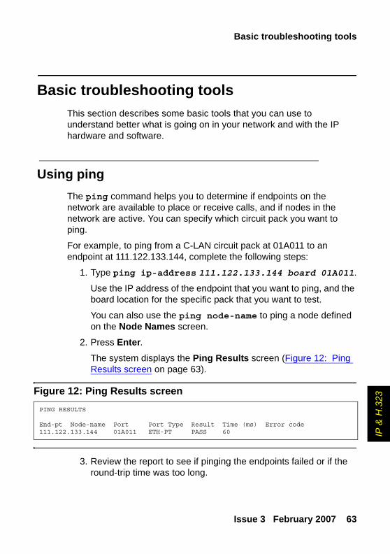
Using ping The ping command helps you to determine if endpoints on the network are available to place or receive calls, and if nodes in the network are active. You can specify which circuit pack you want to ping.
For example, to ping from a C-LAN circuit pack at 01A011 to an endpoint at 111.122.133.144, complete the following steps:
1. Type ping ip-address 111.122.133.144 board 01A011.
Use the IP address of the endpoint that you want to ping, and the board location for the specific pack that you want to test.
You can also use the ping node-name to ping a node defined on the Node Names screen.
2. Press Enter.The system displays the Ping Results screen (Figure 12: Ping Results screen on page 63).
Figure 12: Ping Results screen
3. Review the report to see if pinging the endpoints failed or if the round-trip time was too long.
PING RESULTS
End-pt Node-name Port Port Type Result Time (ms) Error code111.122.133.144 01A011 ETH-PT PASS 60
Solving IP and H.323 problems
64 Basic Diagnostics Quick Reference
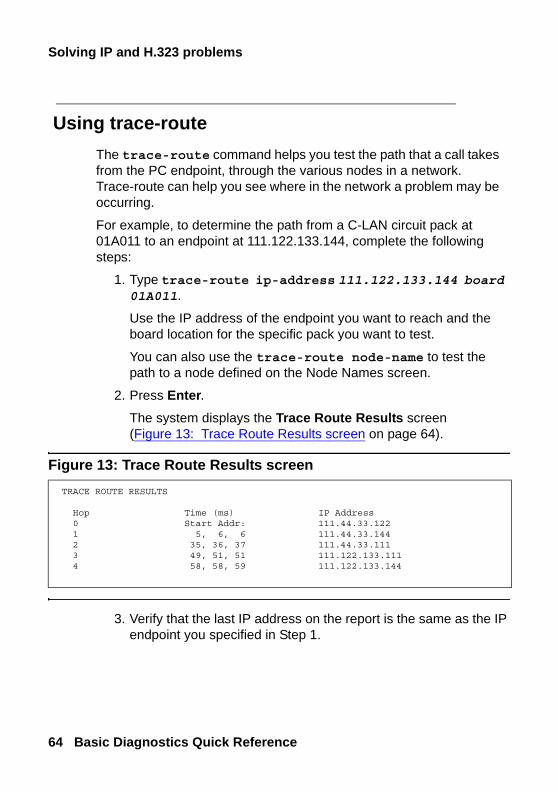
Using trace-route The trace-route command helps you test the path that a call takes from the PC endpoint, through the various nodes in a network. Trace-route can help you see where in the network a problem may be occurring.
For example, to determine the path from a C-LAN circuit pack at 01A011 to an endpoint at 111.122.133.144, complete the following steps:
1. Type trace-route ip-address 111.122.133.144 board 01A011.
Use the IP address of the endpoint you want to reach and the board location for the specific pack you want to test.
You can also use the trace-route node-name to test the path to a node defined on the Node Names screen.
2. Press Enter.The system displays the Trace Route Results screen (Figure 13: Trace Route Results screen on page 64).
Figure 13: Trace Route Results screen
3. Verify that the last IP address on the report is the same as the IP endpoint you specified in Step 1.
TRACE ROUTE RESULTS
Hop Time (ms) IP Address0 Start Addr: 111.44.33.1221 5, 6, 6 111.44.33.1442 35, 36, 37 111.44.33.1113 49, 51, 51 111.122.133.1114 58, 58, 59 111.122.133.144

Basic troubleshooting tools
Issue 3 February 2007 65
IP &
H.3
23
If the system was unable to follow the full path, it lists the last address that it could successfully reach. This information may help you narrow which part of the network is experiencing problems.
Finding the IP addressIn some cases, you will want to know the IP address of a PC so that you can ping it or trace the route of a call to it. To determine the IP address, complete the following steps:
1. At the PC, open a Command Prompt (DOS) window.
Typically you can access the command prompt by selecting Start > Programs > Command Prompt.
2. At the Command prompt, type winnt\system32\ipconfig (Windows NT/2000) or winipcfg (Windows 95/98).
3. Record the IP address for the PC.
Verifying the IP Softphone registrationSometimes you will need to know whether or not an IP Softphone is registered. For example, to determine whether the Softphone at extension 4455 is registered, complete the following steps:
1. Type status station 4455. Press Enter.The system displays the General Status screen.
2. Look at the Registration Status field on the second page. If the word “authenticated” appears, the Softphone is registered.

Solving IP and H.323 problems
66 Basic Diagnostics Quick Reference
Verifying the trunk typeSometimes you will need to know whether or not a trunk group is an IP type endpoint. For example, to determine whether the trunk member 01 of trunk group 40 is an IP endpoint, complete the following steps:
1. Type status trunk 40/01. Press Enter.The system displays the Trunk Status screen.
2. Verify that the Port field is T000nn.
If this field displays a standard port address (for example, 01A0210), then the trunk is not an IP endpoint.
When all else failsReboot the PC. When you are experiencing unexpected behavior that you cannot easily fix, you may want to close all your applications and reboot the machine.
! WARNING:WARNING: Some system platforms also run on a PC. If you
reboot a system PC that is running a D1, all calls will be lost. In that case, you might want to wait until after normal business hours to reboot the PC.
Preparing to contact Avaya
Issue 3 February 2007 67
cont
actin
g
7: Contacting Avaya
This section describes what information you should have handy when you need to contact the Avaya Technical Service Center (TSC). This section also provides a list of telephone numbers you can call when you have a problem with your system.
Preparing to contact AvayaDo you need to call Avaya for additional information or help in solving a problem? If you do, please have the following information handy. This helps the person taking your call.
● your name and number (in case we need to call you back)
● your installation location number (also called your IL)
___________________________________ (Write your IL number here for easy reference)
● your company’s main telephone number
● the type of your system
● the number of trunks on your system
● the number of stations on your system
Also, use the information in this book to determine the possible source of your problem. It always helps to keep a log of the steps you took and the information you gathered while performing your diagnosis. This information is extremely helpful when you partner with an Avaya representative in solving your system problems.

Contacting Avaya
68 Basic Diagnostics Quick Reference
Remember, if the problem is with equipment or service outside of your own equipment, you need to call your vendor or service provider. If you determine that the problem is with your own equipment, such as on your own stations, system, or trunks, give Avaya a call.If you are not sure where the problem is located, double-check your system information. Refer to Problem solving strategies on page 13 for more information.Be ready to talk about:
● the problem you want to solve
● if the problem is with a new component or feature
● if something that used to work now does not work
● any numbers involved with the problem (for example, extensions or telephone numbers, trunk group numbers, telephone types, or report types)
● the contents of any recorded messages received
● error messages from the system
● type of ringback tones received on telephones
● the names and numbers of your vendors
● any other pertinent information

Contacting Avaya
Issue 3 February 2007 69
cont
actin
g
Contacting AvayaThe following table lists additional services available to you. If you are outside of the 1 800 calling area, contact your local Avaya representative.
Technical Service Center for Large-Systems Customers and Toll Fraud Crisis Intervention (for help with repairs)
1 800 242 2121
Communication Manager Helpline (for administration and software problems, including vectors, how features work, administration, and interactions)
1 800 225 7585

Contacting Avaya
70 Basic Diagnostics Quick Reference
Issue 3 February 2007 71
Index
Index
AACA, see Automatic Circuit Assurance (ACA)alarms
buttons . . . . . . . . . . . . . 40classifications of . . . . . . . . . 36clearing . . . . . . . . . . . . . 39DS1 . . . . . . . . . . . . . . 45logs. . . . . . . . . . . . . . . 36off-board . . . . . . . . . . . . 37on-board . . . . . . . . . . . . 37preventing . . . . . . . . . . . . 43
Automatic Circuit Assurance (ACA) . . . 48
Bbackups . . . . . . . . . . . . . . 11baselining
definition . . . . . . . . . . . . 7retrieving information . . . . . . . 8
busy-verifyhunt groups . . . . . . . . . . . 50trunks . . . . . . . . . . . . . . 51
buttonsAlarm . . . . . . . . . . . . . . 40Busy Verify . . . . . . . . . . . 49Trunk ID. . . . . . . . . . . . . 55
Ccabinet
viewing status . . . . . . . . . . 16circuit pack
removing . . . . . . . . . . . . 44clearing
alarms . . . . . . . . . . . . . 39errors . . . . . . . . . . . . . . 35
commandschange circuit-pack . . . . . . . . 45change data-module extension . . . 43clear amw all . . . . . . . . . . . 22display alarms . . . . . . . . 13, 37display errors. . . . . . . 13, 32, 41list integrated-annc-boards . . . . . 27ping. . . . . . . . . . . . . . . 63release . . . . . . . . . . . . . 40save announcements . . . . . . . 11save translations . . . . . . . . . 11status . . . . . . . . . . . . 13, 14status health . . . . . . . . . . . 15status station . . . . . 16, 22, 62, 65status system all-cabinets . . . . . 16status trunk . . . . . . . . . 62, 66test station extension . . . . . . . 42trace-route . . . . . . . . . . . . 64
Ddiagnosing problems . . . . . . . . . 19DS1 alarms . . . . . . . . . . . . . 45
Eerror logs
interpreting. . . . . . . . . . . . 35viewing . . . . . . . . . . . . . 31
error types . . . . . . . . . . . . . 401, circuit pack removed . . . . . . 4318, busied out . . . . . . . . . . 40513, equipment missing . . . . . . 42
errorsclearing . . . . . . . . . . . . . 35preventing . . . . . . . . . . . . 43
72 Basic Diagnostics Quick Reference
Index
FFacility Busy Indication . . . . . . . . 52Facility Test Calls . . . . . . . . . . 53
HH.323 trunk . . . . . . . . . . . . . 57hunt groups, busy-verify . . . . . . . . 50
IIL number, see installation location (IL)
numberinstallation location (IL) number. . . . . 67internet protocol (IP) . . . . . . . . . 57IP address . . . . . . . . . . . . . 65IP Softphone . . . . . . . . . . . . 57
Llogin problems. . . . . . . . . . . . 25logs
alarms . . . . . . . . . . . . . 36clearing alarms . . . . . . . . . . 39error . . . . . . . . . . . . . . 31
Mmaintaining records . . . . . . . . . 8maintenance objects (MO). . . . . . . 31
Ppassword problems. . . . . . . . . . 25printer problems . . . . . . . . . . . 24problems
call center . . . . . . . . . . . . 25diagnosing . . . . . . . . . . . . 19dialing out . . . . . . . . . . . . 21incoming calls . . . . . . . . . . 22login . . . . . . . . . . . . . . 25
problems, (continued)message lamp . . . . . . . . . . 22modem . . . . . . . . . . . . . 24password . . . . . . . . . . . . 25printer . . . . . . . . . . . . . . 24SAT . . . . . . . . . . . . . . 25Softphone . . . . . . . . . . . . 57sound quality . . . . . . . . . . . 60telephone . . . . . . . . . . . . 20terminal access . . . . . . . . . . 25tie trunks . . . . . . . . . . . . 23trunks . . . . . . . . . . . . . . 23
problem-solving strategies . . . . . . . 13
Rrecords maintenance . . . . . . . . . 8removing circuit packs . . . . . . . . 44reports
error . . . . . . . . . . . . . . 31
SSAT problems . . . . . . . . . . . . 25screens
Alarm Report . . . . . . . . . 38, 39Data Module . . . . . . . . . . . 44Error Report . . . . . . . . . . . 32General Status . . . . . . . . . . 16Hardware Error Report . . . 34, 41, 42Help . . . . . . . . . . . . . . 14Ping Results . . . . . . . . . . . 63Status Health. . . . . . . . . . . 15System Status Cabinet. . . . . . . 17Trace Route Results. . . . . . . . 64
securityaccess codes. . . . . . . . . . . 53
Softphone, solving problems . . . . . . 57status
cabinet . . . . . . . . . . . . . 16station. . . . . . . . . . . . . . 15system health . . . . . . . . . . 15
strategies, problem-solving . . . . . . 13system
backups . . . . . . . . . . . . . 11health . . . . . . . . . . . . . . 15status . . . . . . . . . . . . . . 14
Issue 3 February 2007 73
Index
system logsalarms . . . . . . . . . . . . . 31errors . . . . . . . . . . . . . . 31
Ttelephones
busy-verify . . . . . . . . . . . . 49problem solving. . . . . . . . . . 20
terminal access problems . . . . . . . 25testing
busy telephones . . . . . . . . . 49phones . . . . . . . . . . . . . 53trunks . . . . . . . . . . . . . . 53turning-off . . . . . . . . . . . . 43
troubleshootingtelephone problems . . . . . . . . 20trunks . . . . . . . . . . . . . . 55
Trunk Identification . . . . . . . . . . 55trunks
busy-verify . . . . . . . . . . . . 51identifying problems . . . . . . 23, 62troubleshooting . . . . . . . . . . 55
Vviewing
error logs . . . . . . . . . . . . 31station status . . . . . . . . . . . 15system status . . . . . . . . . . 14

74 Basic Diagnostics Quick Reference
Index