
Avatar : Bending Rigid Bodies - PhysBAMphysbam.stanford.edu/~mlentine/images/deformingrigids.pdf ·...
1
Avatar : Bending Rigid Bodies Brice Criswell * Industrial Light + Magic Michael Lentine † Industrial Light + Magic Steve Sauers ‡ Industrial Light + Magic Figure 1: Figure: Avatar (c) Industrial Light & Magic. All rights reserved. 1 Introduction Simulating bending and denting of rigid materials has become an increasingly important aspect for modeling the realistic destruction of objects. Historically, modeling these phenomena has been a te- dious and time consuming process for the artists at Industrial Light & Magic. Typically the artists would manually shape the rigid bod- ies after the simulation to produce this realistic look. However, for the movie Avatar, we have developed a new system that seamlessly transitions between rigid and deformable simulations allowing the artists to achieve realistic destruction without the need to apply any post corrective shapes. To solve this problem, we used a low resolution spring-mass sim- ulation as a pre-processing step to the rigid body simulator. At the start of the simulation, a tetrahedral and thin shell representation of the rigid bodies was initialized as a spring cage to model the sur- face deformations during the rigid simulation. At the beginning of each relevant frame, the cages were advanced using a spring-mass simulator and their resulting deformations were transferred to the surface of the rigid bodies. After all the objects are processed, the rigid bodies were advanced using a rigid body simulator. The re- sults allowed for a quick and realistic deformation of rigid bodies that could be used for complex scenes such as those shown in Fig- ure 1. 2 Mesh Generation During initialization of the simulation we automatically generated a tetrahedral mesh to represent the interior region of the rigid body. The tetrahedral mesh and the triangulated surface of rigid body were initialized as a set of deformable objects that were connected through a series of springs. The tetrahedral mesh defines a set of volumetric altitude springs that controlled the restorative properties of the rigid body volume, and the rigid body surface defined a set of surface tension springs that provided controls over surface bend- ing and stretching properties. We also created a set of alignment springs to connect the volumetric and surface springs. For stability and robustness we used unconditionally stable springs allowing us to take rather large time steps. * e-mail: [email protected] † e-mail:[email protected] ‡ [email protected] 3 Simulation At the beginning of each frame, each rigid body was analyzed to determine which objects might interact due to collisions or other interacting forces. The simulation system collects the potential im- pulses between objects and determined which rigid objects needed to be simulated as deformable objects. Any objects that are not interacting with other objects in a significant way remained rigid bodies during the deformable evolution. Next the solver advanced the deformable objects and all non- deforming rigid bodies. If the deforming surfaces experienced a noticeable change, the rigid bodies were updated from the resulting deformations to reflect changes in the surface and mass distribution. We note that for this advancement, the frame length and time step size were set separately from the standard frame length of the final rigid body evolution. The length of the deformable evolution was adjustable so it could run slightly longer than a standard animation frame, allowing for more exaggerated deformations. During the deformable evolution, all simulation objects needed to experience the same forces and constraints that effected their as- sociated rigid bodies. This required the consideration of all our existing constraints currently used by the artists. The deformable cage could be effected by wind, pulled by stiction, frozen within the clustering system, and attached to the various other simulation controls. The addition of the external controls allowed the result- ing deformations of rigid bodies to accurately reflect its simulation environment. After the deformable evolution, the solver was rewound to the be- ginning of the frame with the modified rigid bodies. Finally, the rigid objects were simulated to process the collisions and con- straints on the updated surface. Special thanks to : Ron Fedkiw, Michael DiComo, Karin Cooper References BRIDSON, R., MARINO, S., AND FEDKIW, R. 2003. Simulation of clothing with folds and wrinkles. 28–36. GUENDELMAN, E., BRIDSON, R., AND FEDKIW, R. 2003. Nonconvex rigid bodies with stacking. ACM Trans. Graph. (SIGGRAPH Proc.) 22, 3, 871–878.
Transcript of Avatar : Bending Rigid Bodies - PhysBAMphysbam.stanford.edu/~mlentine/images/deformingrigids.pdf ·...
Avatar : Bending Rigid Bodies
Brice Criswell∗
Industrial Light + MagicMichael Lentine†
Industrial Light + MagicSteve Sauers‡
Industrial Light + Magic
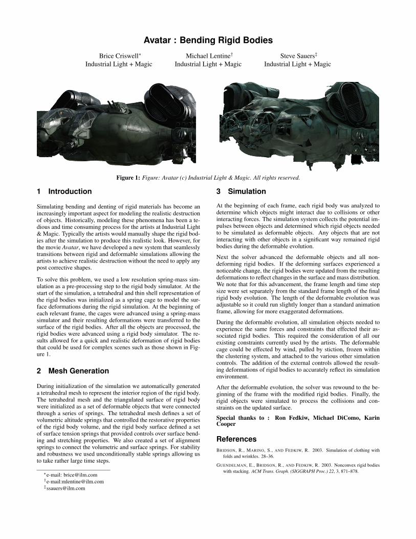
Figure 1: Figure: Avatar (c) Industrial Light & Magic. All rights reserved.
1 Introduction
Simulating bending and denting of rigid materials has become anincreasingly important aspect for modeling the realistic destructionof objects. Historically, modeling these phenomena has been a te-dious and time consuming process for the artists at Industrial Light& Magic. Typically the artists would manually shape the rigid bod-ies after the simulation to produce this realistic look. However, forthe movie Avatar, we have developed a new system that seamlesslytransitions between rigid and deformable simulations allowing theartists to achieve realistic destruction without the need to apply anypost corrective shapes.
To solve this problem, we used a low resolution spring-mass sim-ulation as a pre-processing step to the rigid body simulator. At thestart of the simulation, a tetrahedral and thin shell representation ofthe rigid bodies was initialized as a spring cage to model the sur-face deformations during the rigid simulation. At the beginning ofeach relevant frame, the cages were advanced using a spring-masssimulator and their resulting deformations were transferred to thesurface of the rigid bodies. After all the objects are processed, therigid bodies were advanced using a rigid body simulator. The re-sults allowed for a quick and realistic deformation of rigid bodiesthat could be used for complex scenes such as those shown in Fig-ure 1.
2 Mesh Generation
During initialization of the simulation we automatically generateda tetrahedral mesh to represent the interior region of the rigid body.The tetrahedral mesh and the triangulated surface of rigid bodywere initialized as a set of deformable objects that were connectedthrough a series of springs. The tetrahedral mesh defines a set ofvolumetric altitude springs that controlled the restorative propertiesof the rigid body volume, and the rigid body surface defined a setof surface tension springs that provided controls over surface bend-ing and stretching properties. We also created a set of alignmentsprings to connect the volumetric and surface springs. For stabilityand robustness we used unconditionally stable springs allowing usto take rather large time steps.
∗e-mail: [email protected]†e-mail:[email protected]‡[email protected]
3 Simulation
At the beginning of each frame, each rigid body was analyzed todetermine which objects might interact due to collisions or otherinteracting forces. The simulation system collects the potential im-pulses between objects and determined which rigid objects neededto be simulated as deformable objects. Any objects that are notinteracting with other objects in a significant way remained rigidbodies during the deformable evolution.
Next the solver advanced the deformable objects and all non-deforming rigid bodies. If the deforming surfaces experienced anoticeable change, the rigid bodies were updated from the resultingdeformations to reflect changes in the surface and mass distribution.We note that for this advancement, the frame length and time stepsize were set separately from the standard frame length of the finalrigid body evolution. The length of the deformable evolution wasadjustable so it could run slightly longer than a standard animationframe, allowing for more exaggerated deformations.
During the deformable evolution, all simulation objects needed toexperience the same forces and constraints that effected their as-sociated rigid bodies. This required the consideration of all ourexisting constraints currently used by the artists. The deformablecage could be effected by wind, pulled by stiction, frozen withinthe clustering system, and attached to the various other simulationcontrols. The addition of the external controls allowed the result-ing deformations of rigid bodies to accurately reflect its simulationenvironment.
After the deformable evolution, the solver was rewound to the be-ginning of the frame with the modified rigid bodies. Finally, therigid objects were simulated to process the collisions and con-straints on the updated surface.
Special thanks to : Ron Fedkiw, Michael DiComo, KarinCooper
ReferencesBRIDSON, R., MARINO, S., AND FEDKIW, R. 2003. Simulation of clothing with
folds and wrinkles. 28–36.
GUENDELMAN, E., BRIDSON, R., AND FEDKIW, R. 2003. Nonconvex rigid bodieswith stacking. ACM Trans. Graph. (SIGGRAPH Proc.) 22, 3, 871–878.


