AvaSpec AS(M&C)-5216 OEM MANUAL 2013-06-01 - …MC)-5216OEMMANUAL.pdf · June-13 AvaSpec...
75
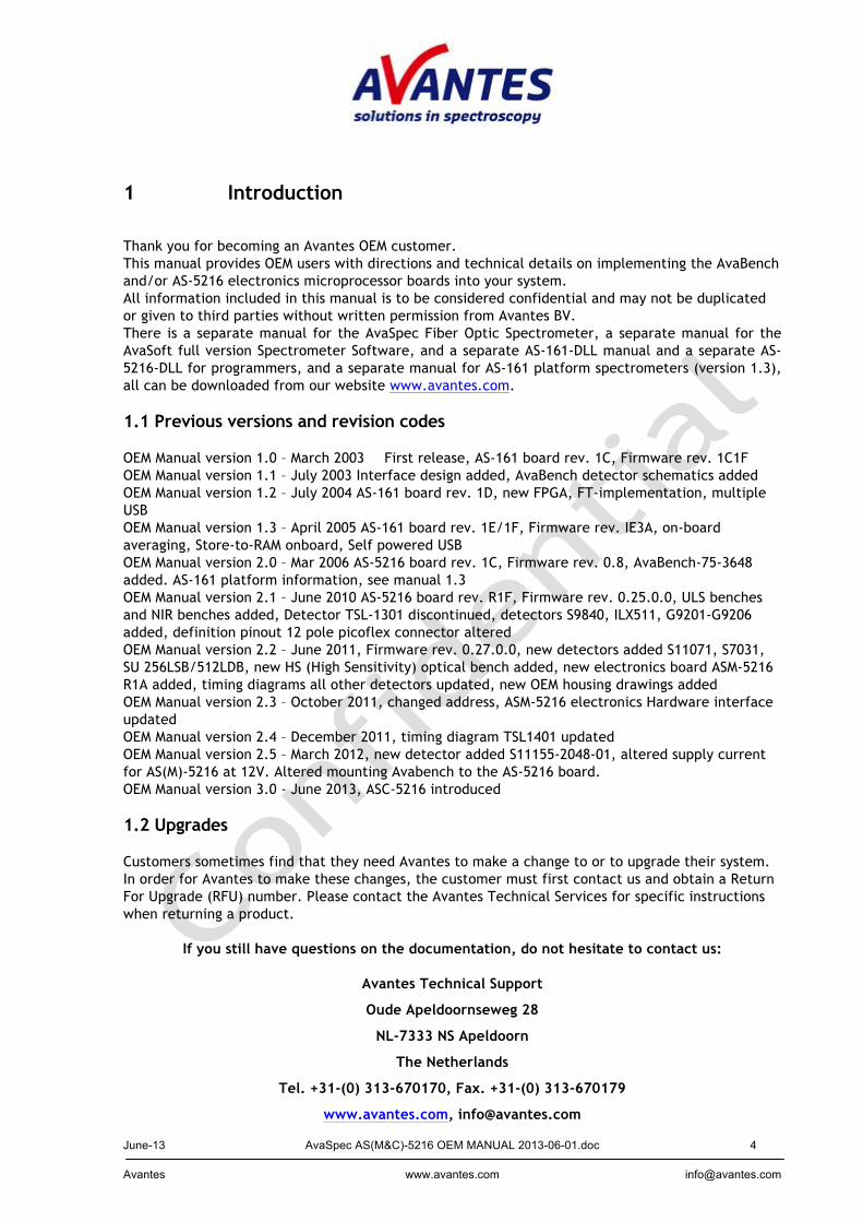
June-13 AvaSpec AS(M&C)-5216 OEM MANUAL 2013-06-01.doc 1 Avantes www.avantes.com [email protected] AvaSpec OEM manual AS-5216 - ASM-5216 - ASC5216 Version 3.0 June 2013
Transcript of AvaSpec AS(M&C)-5216 OEM MANUAL 2013-06-01 - …MC)-5216OEMMANUAL.pdf · June-13 AvaSpec...
June-13 AvaSpec AS(M&C)-5216 OEM MANUAL 2013-06-01.doc 1 Avantes www.avantes.com [email protected]
AvaSpec OEM manual
AS-5216 - ASM-5216 - ASC5216
Version 3.0
June 2013
June-13 AvaSpec AS(M&C)-5216 OEM MANUAL 2013-06-01.doc 2 Avantes www.avantes.com [email protected]
TABLE OF CONTENTS
1 INTRODUCTION ................................................................................................ 4 1.1 PREVIOUS VERSIONS AND REVISION CODES ..................................................................................................... 4 1.2 UPGRADES ....................................................................................................................................................... 4
2 AS/ASM/ASC-5216 MICROPROCESSOR BOARDS .......................................................... 5 2.0.1 AS-5216 INTRODUCTION .............................................................................................................................. 5 2.0.2 ASM-5216 INTRODUCTION .......................................................................................................................... 6 2.0.3 ASC-5216 INTRODUCTION ........................................................................................................................... 6 2.1 FUNCTIONAL DESIGN AS/ASM/ASC-5216 ................................................................................................. 7 2.2 TECHNICAL SPECIFICATIONS AS(M)-5216 .................................................................................................. 8 2.3 AS(M/C)-5216 DETECTOR TIMING SIGNALS ............................................................................................... 9
2.3.1 AvaBench-128-U2 TSL1401 ................................................................................................................ 9 2.3.2 AvaBench-256/1024-U2 HAMS8378 ................................................................................................. 10 2.3.3 AvaBench-2048(L)-U2 ILX554B/ILX511B signals ........................................................................... 12 2.3.3.1 External trigger mode ..................................................................................................................... 13 2.3.4 AvaBench-3648-U2 TCD1304 signals .............................................................................................. 14 2.3.5 AvaBench-75-2048x14 HAM S9840 detector control signals ........................................................... 16 2.3.6 AvaBench-75-ULS2048x16 HAM S11071-1104 detector control signals ......................................... 18 2.3.7 AvaBench-75-ULS2048x64 HAM S11071-1106 detector control signals ......................................... 20 2.3.8 AvaBench-75-ULS2048XL HAM S11155-2048-01 detector control signals ..................................... 22 2.3.9 AvaBench-75-HS1024x58 HAM S7031-1006 detector control signals ............................................. 23 2.3.10 AvaBench-75-HS1024x122 HAM S7031-1007 detector control signals ......................................... 25 2.3.11 AvaBench-NIR256-U2 HAM G9201/G9207 signals ...................................................................... 27 2.3.12 AvaBench-NIR256TEC-U2 SU 256LSB signals ............................................................................ 28 2.3.13 AvaBench-NIR512TEC-U2 SU 512LDB signals ........................................................................... 29
2.4 INTERFACE DESIGN AVASPEC RS232/USB INTERFACE ............................................................................ 30 2.5 AS-5216 ELECTRONICS HARDWARE INTERFACES .................................................................................... 42 2.6 AS-5216 BOARD DIMENSIONS ................................................................................................................. 48 2.7 ASM-5216 ELECTRONICS HARDWARE INTERFACES ................................................................................. 49 2.8 ASM-5216 BOARD DIMENSIONS .............................................................................................................. 52
2.9 ASC-5216 BOARD DIMENSIONS ................................................................................................................ 53
3.1 AVABENCH UV/VIS OPTICAL BENCHES ....................................................................................................... 54 3.2 AVABENCH NIR OPTICAL BENCHES ............................................................................................................. 55 3.3 AVABENCH EXTERNAL SENSOR CONNECTOR ........................................................................................... 56
3.3.1 AvaBench-45-128-U2 Detector schematics ....................................................................................... 58 3.3.2 AvaBench-45-256-U2 Detector schematics ....................................................................................... 58 3.3.3 AvaBench-75-1024-U2 Detector schematics ..................................................................................... 59 3.3.4 AvaBench-75-2048(L)-U2 Detector schematics ................................................................................ 59 3.3.5 AvaBench-75-3648–U2 Detector schematics .................................................................................... 60 3.3.6 AvaBench-75-2048x14–U2 Detector schematics .............................................................................. 60 3.3.7 AvaBench-75-ULS2048x16/64–U2 Detector schematics .................................................................. 61 3.3.8 AvaBench-75-ULS2048XL–U2 Detector schematics ........................................................................ 62 3.3.9 AvaBench-HS1024x58/122TEC–U2 Detector schematics ................................................................ 63 3.3.10 AvaBench-50-NIR256–U2 Detector schematics .............................................................................. 64 3.3.11 AvaBench-50-NIR256TEC–U2 Detector schematics ...................................................................... 64 3.3.12 AvaBench-50-NIR256/512TEC–U2 Detector schematics ............................................................... 65
3.4 AVABENCH DIMENSIONS .......................................................................................................................... 66 3.4.1 AvaBench-45 dimensions .................................................................................................................. 66 3.4.2 AvaBench-75 dimensions .................................................................................................................. 67 3.4.5 AvaBench-HS dimensions ................................................................................................................. 70

June-13 AvaSpec AS(M&C)-5216 OEM MANUAL 2013-06-01.doc 3 Avantes www.avantes.com [email protected]
3.4.6 AvaBench-50 dimensions .................................................................................................................. 71 3.4.7 AvaBench-50TEC dimensions ........................................................................................................... 72
3.4.8 ULSi dimensions ................................................................................................................................... 73
..................................................................................................................... ERROR! BOOKMARK NOT DEFINED. 3.5 MOUNTING AVABENCHES TO THE AS-5216 BOARD ................................................................................. 74 4. OEM HOUSINGS .......................................................................................................................................... 75 4.1 SINGLE CHANNEL HOUSING ........................................................................................................................... 75 4.2 DUAL CHANNEL HOUSING ............................................................................................................................. 75
APPENDIX A: DATA ELEMENTS STRUCTURE ................................................................... 1
June-13 AvaSpec AS(M&C)-5216 OEM MANUAL 2013-06-01.doc 4 Avantes www.avantes.com [email protected]
1 Introduction Thank you for becoming an Avantes OEM customer. This manual provides OEM users with directions and technical details on implementing the AvaBench and/or AS-5216 electronics microprocessor boards into your system. All information included in this manual is to be considered confidential and may not be duplicated or given to third parties without written permission from Avantes BV. There is a separate manual for the AvaSpec Fiber Optic Spectrometer, a separate manual for the AvaSoft full version Spectrometer Software, and a separate AS-161-DLL manual and a separate AS-5216-DLL for programmers, and a separate manual for AS-161 platform spectrometers (version 1.3), all can be downloaded from our website www.avantes.com. 1.1 Previous versions and revision codes OEM Manual version 1.0 – March 2003 First release, AS-161 board rev. 1C, Firmware rev. 1C1F OEM Manual version 1.1 – July 2003 Interface design added, AvaBench detector schematics added OEM Manual version 1.2 – July 2004 AS-161 board rev. 1D, new FPGA, FT-implementation, multiple USB OEM Manual version 1.3 – April 2005 AS-161 board rev. 1E/1F, Firmware rev. IE3A, on-board averaging, Store-to-RAM onboard, Self powered USB OEM Manual version 2.0 – Mar 2006 AS-5216 board rev. 1C, Firmware rev. 0.8, AvaBench-75-3648 added. AS-161 platform information, see manual 1.3 OEM Manual version 2.1 – June 2010 AS-5216 board rev. R1F, Firmware rev. 0.25.0.0, ULS benches and NIR benches added, Detector TSL-1301 discontinued, detectors S9840, ILX511, G9201-G9206 added, definition pinout 12 pole picoflex connector altered OEM Manual version 2.2 – June 2011, Firmware rev. 0.27.0.0, new detectors added S11071, S7031, SU 256LSB/512LDB, new HS (High Sensitivity) optical bench added, new electronics board ASM-5216 R1A added, timing diagrams all other detectors updated, new OEM housing drawings added OEM Manual version 2.3 – October 2011, changed address, ASM-5216 electronics Hardware interface updated OEM Manual version 2.4 – December 2011, timing diagram TSL1401 updated OEM Manual version 2.5 – March 2012, new detector added S11155-2048-01, altered supply current for AS(M)-5216 at 12V. Altered mounting Avabench to the AS-5216 board. OEM Manual version 3.0 - June 2013, ASC-5216 introduced 1.2 Upgrades Customers sometimes find that they need Avantes to make a change to or to upgrade their system. In order for Avantes to make these changes, the customer must first contact us and obtain a Return For Upgrade (RFU) number. Please contact the Avantes Technical Services for specific instructions when returning a product.
If you still have questions on the documentation, do not hesitate to contact us:
Avantes Technical Support
Oude Apeldoornseweg 28
NL-7333 NS Apeldoorn
The Netherlands
Tel. +31-(0) 313-670170, Fax. +31-(0) 313-670179
www.avantes.com, [email protected]
June-13 AvaSpec AS(M&C)-5216 OEM MANUAL 2013-06-01.doc 5 Avantes www.avantes.com [email protected]
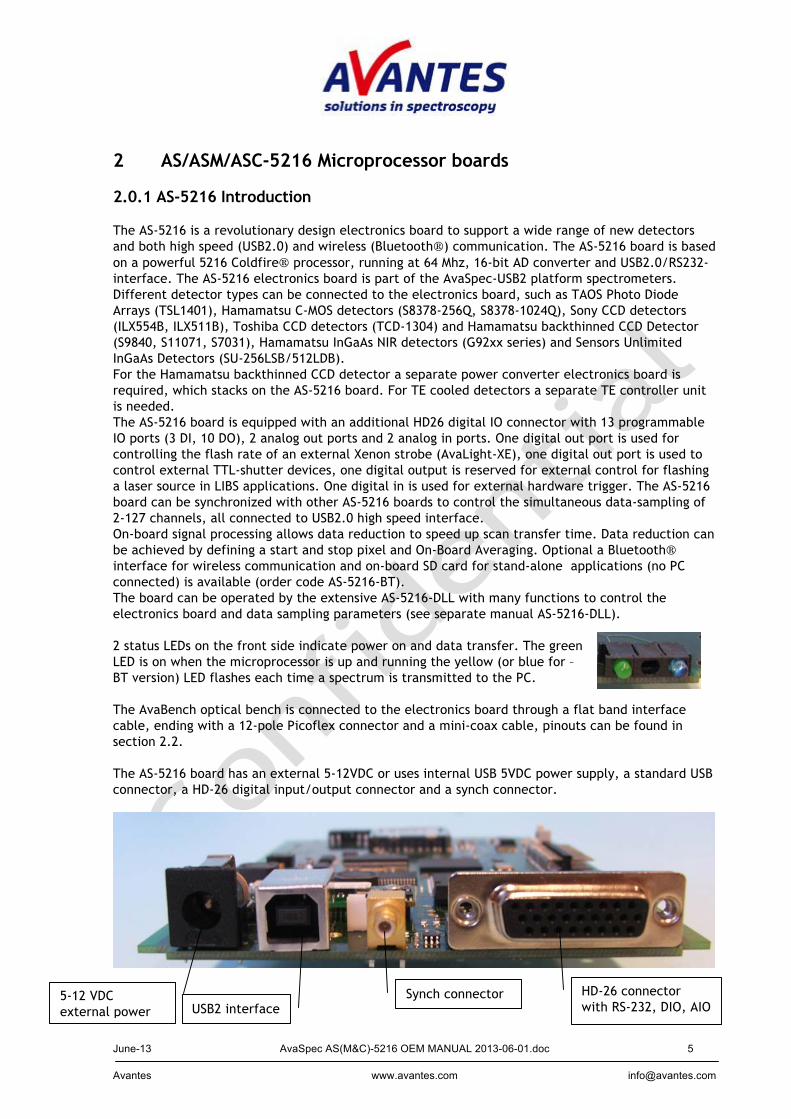
2 AS/ASM/ASC-5216 Microprocessor boards 2.0.1 AS-5216 Introduction The AS-5216 is a revolutionary design electronics board to support a wide range of new detectors and both high speed (USB2.0) and wireless (Bluetooth) communication. The AS-5216 board is based on a powerful 5216 Coldfire processor, running at 64 Mhz, 16-bit AD converter and USB2.0/RS232-interface. The AS-5216 electronics board is part of the AvaSpec-USB2 platform spectrometers. Different detector types can be connected to the electronics board, such as TAOS Photo Diode Arrays (TSL1401), Hamamatsu C-MOS detectors (S8378-256Q, S8378-1024Q), Sony CCD detectors (ILX554B, ILX511B), Toshiba CCD detectors (TCD-1304) and Hamamatsu backthinned CCD Detector (S9840, S11071, S7031), Hamamatsu InGaAs NIR detectors (G92xx series) and Sensors Unlimited InGaAs Detectors (SU-256LSB/512LDB). For the Hamamatsu backthinned CCD detector a separate power converter electronics board is required, which stacks on the AS-5216 board. For TE cooled detectors a separate TE controller unit is needed. The AS-5216 board is equipped with an additional HD26 digital IO connector with 13 programmable IO ports (3 DI, 10 DO), 2 analog out ports and 2 analog in ports. One digital out port is used for controlling the flash rate of an external Xenon strobe (AvaLight-XE), one digital out port is used to control external TTL-shutter devices, one digital output is reserved for external control for flashing a laser source in LIBS applications. One digital in is used for external hardware trigger. The AS-5216 board can be synchronized with other AS-5216 boards to control the simultaneous data-sampling of 2-127 channels, all connected to USB2.0 high speed interface. On-board signal processing allows data reduction to speed up scan transfer time. Data reduction can be achieved by defining a start and stop pixel and On-Board Averaging. Optional a Bluetooth interface for wireless communication and on-board SD card for stand-alone applications (no PC connected) is available (order code AS-5216-BT). The board can be operated by the extensive AS-5216-DLL with many functions to control the electronics board and data sampling parameters (see separate manual AS-5216-DLL). 2 status LEDs on the front side indicate power on and data transfer. The green LED is on when the microprocessor is up and running the yellow (or blue for –BT version) LED flashes each time a spectrum is transmitted to the PC. The AvaBench optical bench is connected to the electronics board through a flat band interface cable, ending with a 12-pole Picoflex connector and a mini-coax cable, pinouts can be found in section 2.2. The AS-5216 board has an external 5-12VDC or uses internal USB 5VDC power supply, a standard USB connector, a HD-26 digital input/output connector and a synch connector.
5-12 VDC external power USB2 interface
Synch connector HD-26 connector with RS-232, DIO, AIO

June-13 AvaSpec AS(M&C)-5216 OEM MANUAL 2013-06-01.doc 6 Avantes www.avantes.com [email protected]
2.0.2 ASM-5216 Introduction The ASM-5216 is the OEM version of our AS-5216 board with more than 25% reduced size and price and additional interfaces for optimal coupling with other devices. The ASM-5216 supports all Avantes USB2 optical Benches with a wide range of new detectors and high speed (USB2.0) communication. The ASM-5216 board is based on a powerful 5216 Coldfire processor, running at 64 Mhz, 16-bit AD converter and USB2.0/RS232-interface. The ASM-5216 electronics board is part of the 3rd generation AvaSpec platform spectrometers. Different detector types can be connected to the electronics board, such as TAOS Photo Diode Arrays ( TSL1401), Sony CCD detectors (ILX511, ILX554B), Toshiba CCD detectors (TCD-1304), Hamamatsu back-thinned CCD detectors (S9840, S11071, S7031), Hamamatsu (G92xx series) and Sensors Unlimited (SU-256LSB/512LDB) InGaAs NIR detectors. For the Hamamatsu back-thinned detector a separate power converter board is needed and for the detectors with TE cooling a separate TE controller board is needed. The board is equipped with a Samtec 60-pin Card edge connector with 12 programmable IO ports (3 DI, 9 DO), 2 analog out ports and 2 analog in ports. One digital out port is used for controlling the flash rate of an external Xenon strobe (AvaLight-XE), one digital out port is used to control external TTL-shutter devices, one digital output is reserved for external control for flashing a laser source in LIBS applications. One digital in is used for external hardware trigger. The AS-5216 board can be synchronized with other AS-5216 boards to control the simultaneous data-sampling of multiple channels, all connected to USB2.0 high speed interface. On-board signal processing allows data reduction to speed up scan transfer time. Data reduction can be achieved by defining a start and stop pixel and On-Board Averaging. The board can be operated by the extensive AS-5216-DLL with many functions to control the electronics board and data sampling parameters 2.0.3 ASC-5216 Introduction The ASC-5216 is a reduced size version of our AS-5216 board, designed to fit into our integrated ULSI housing. It supports the Toshiba TCD-1304 and Sony ILX511& ILX554B detectors. The ASC-5216 board is based on a powerful 5216 Coldfire processor, running at 64 Mhz, 16-bit AD converter and USB2.0/RS232-interface. The ASC-5216 electronics board is part of the 3rd generation AvaSpec platform spectrometers. The board is equipped with a Hirose ST-60-36P connector with 12 programmable IO ports (3 DI, 9 DO), 2 analog out ports and 2 analog in ports. One digital out port is used for controlling the flash rate of an external Xenon strobe (AvaLight-XE), one digital out port is used to control external TTL-shutter devices, and one digital output is reserved for external control for flashing a laser source in LIBS applications. One digital in is used for external hardware trigger. The ASC-5216 board can be synchronized with other ASC-5216 boards to control the simultaneous data-sampling of multiple channels, all connected to USB2.0 high speed interface. On-board signal processing allows data reduction to speed up scan transfer time. Data reduction can be achieved by defining a start and stop pixel and On-Board Averaging. The board can be operated by the extensive AS-5216-DLL with many functions to control the electronics board and data sampling parameters. Please do not forget to connect the earth (ground) cable installed on some optical benches to a grounded surface. Not doing so can result in lock-ups of the spectrometer or the software.
June-13 AvaSpec AS(M&C)-5216 OEM MANUAL 2013-06-01.doc 7 Avantes www.avantes.com [email protected]
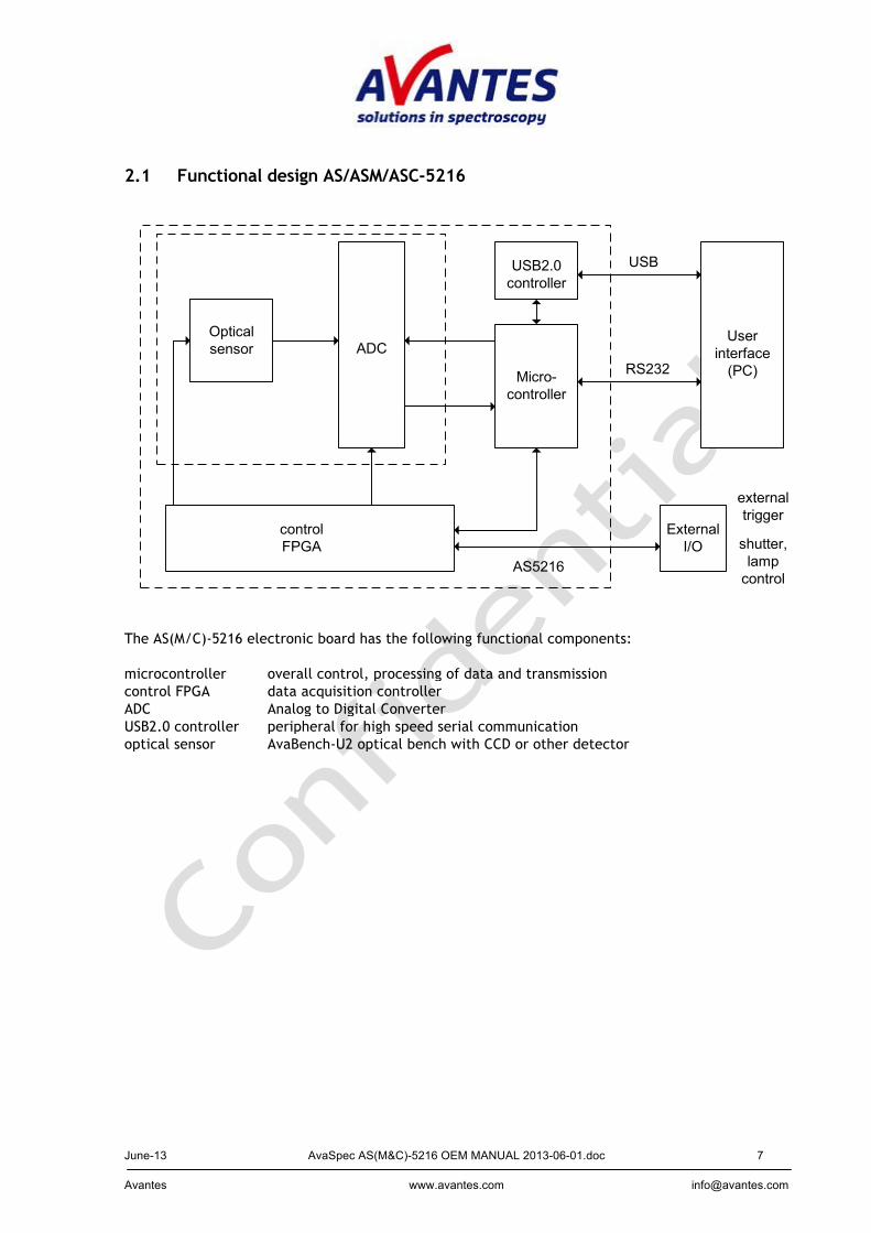
2.1 Functional design AS/ASM/ASC-5216
Micro-controller
Userinterface(PC)
ADC
controlFPGA
ExternalI/O
AS5216
USB
RS232
externaltrigger
shutter,lampcontrol
USB2.0controller
Opticalsensor
The AS(M/C)-5216 electronic board has the following functional components: microcontroller overall control, processing of data and transmission control FPGA data acquisition controller ADC Analog to Digital Converter USB2.0 controller peripheral for high speed serial communication optical sensor AvaBench-U2 optical bench with CCD or other detector
June-13 AvaSpec AS(M&C)-5216 OEM MANUAL 2013-06-01.doc 8 Avantes www.avantes.com [email protected]
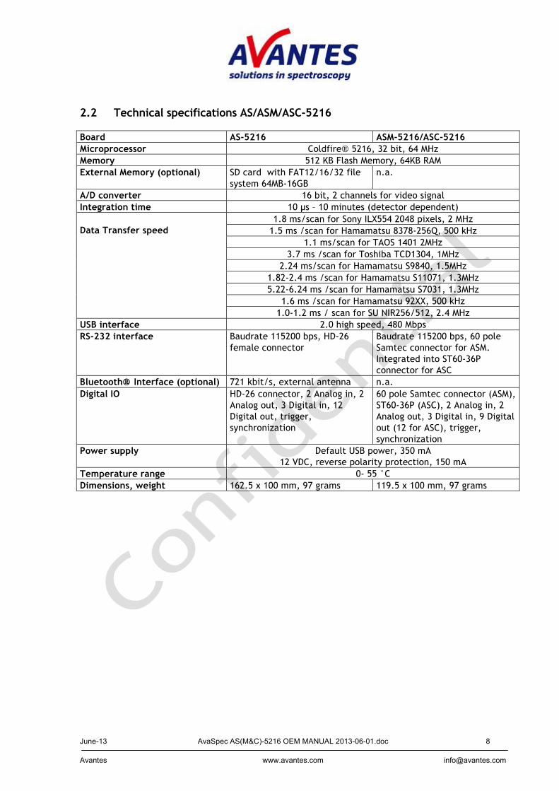
2.2 Technical specifications AS/ASM/ASC-5216 Board AS-5216 ASM-5216/ASC-5216 Microprocessor Coldfire 5216, 32 bit, 64 MHz Memory 512 KB Flash Memory, 64KB RAM External Memory (optional) SD card with FAT12/16/32 file
system 64MB-16GB n.a.
A/D converter 16 bit, 2 channels for video signal Integration time 10 µs – 10 minutes (detector dependent) Data Transfer speed
1.8 ms/scan for Sony ILX554 2048 pixels, 2 MHz 1.5 ms /scan for Hamamatsu 8378-256Q, 500 kHz
1.1 ms/scan for TAOS 1401 2MHz 3.7 ms /scan for Toshiba TCD1304, 1MHz
2.24 ms/scan for Hamamatsu S9840, 1.5MHz 1.82-2.4 ms /scan for Hamamatsu S11071, 1.3MHz 5.22-6.24 ms /scan for Hamamatsu S7031, 1.3MHz
1.6 ms /scan for Hamamatsu 92XX, 500 kHz 1.0-1.2 ms / scan for SU NIR256/512, 2.4 MHz
USB interface 2.0 high speed, 480 Mbps RS-232 interface Baudrate 115200 bps, HD-26
female connector Baudrate 115200 bps, 60 pole Samtec connector for ASM. Integrated into ST60-36P connector for ASC
Bluetooth Interface (optional) 721 kbit/s, external antenna n.a. Digital IO HD-26 connector, 2 Analog in, 2
Analog out, 3 Digital in, 12 Digital out, trigger, synchronization
60 pole Samtec connector (ASM), ST60-36P (ASC), 2 Analog in, 2 Analog out, 3 Digital in, 9 Digital out (12 for ASC), trigger, synchronization
Power supply Default USB power, 350 mA 12 VDC, reverse polarity protection, 150 mA
Temperature range 0- 55 °C Dimensions, weight 162.5 x 100 mm, 97 grams 119.5 x 100 mm, 97 grams
June-13 AvaSpec AS(M&C)-5216 OEM MANUAL 2013-06-01.doc 9 Avantes www.avantes.com [email protected]
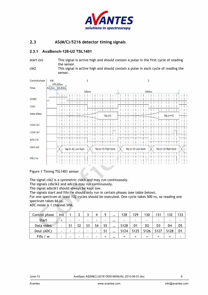
2.3 AS(M/C)-5216 detector timing signals 2.3.1 AvaBench-128-U2 TSL1401 start (si) This signal is active high and should contain a pulse in the first cycle of reading
the sensor. clk2 This signal is active high and should contain a pulse in each cycle of reading the
sensor.
Figure 1 Timing TSL1401 sensor The signal clk2 is a symmetric clock and may run continuously. The signals cdsclk2 and adcclk may run continuously. The signal adsclk1 should always be kept low. The signals start and fifo /w should only run in certain phases (see table below). For one spectrum at least 132 cycles should be executed. One cycle takes 500 ns, so reading one spectrum takes 66 µs. ADC mode is 1 channel SHA.
Control phase Init 1 2 3 4 5 … 128 129 130 131 132 133
Start + - - - - - … - - - - - -
Data video - S1 S2 S3 S4 S5 … S128 D1 D2 D3 D4 D5
Dout (ADC) - - - - - S1 … S124 S125 S126 S127 S128 D1
Fifo / w - - - - - + … + + + + + -
June-13 AvaSpec AS(M&C)-5216 OEM MANUAL 2013-06-01.doc 10 Avantes www.avantes.com [email protected]
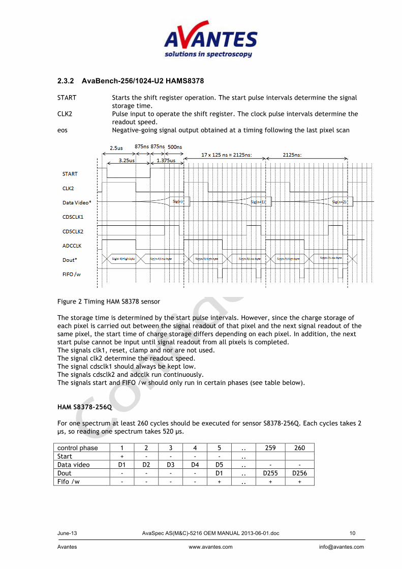
2.3.2 AvaBench-256/1024-U2 HAMS8378 START Starts the shift register operation. The start pulse intervals determine the signal
storage time. CLK2 Pulse input to operate the shift register. The clock pulse intervals determine the
readout speed. eos Negative-going signal output obtained at a timing following the last pixel scan
Figure 2 Timing HAM S8378 sensor The storage time is determined by the start pulse intervals. However, since the charge storage of each pixel is carried out between the signal readout of that pixel and the next signal readout of the same pixel, the start time of charge storage differs depending on each pixel. In addition, the next start pulse cannot be input until signal readout from all pixels is completed. The signals clk1, reset, clamp and nor are not used. The signal clk2 determine the readout speed. The signal cdsclk1 should always be kept low. The signals cdsclk2 and adcclk run continuously. The signals start and FIFO /w should only run in certain phases (see table below).
HAM S8378-256Q
For one spectrum at least 260 cycles should be executed for sensor S8378-256Q. Each cycles takes 2 µs, so reading one spectrum takes 520 µs. control phase 1 2 3 4 5 .. 259 260 Start + - - - - .. Data video D1 D2 D3 D4 D5 .. - - Dout - - - - D1 .. D255 D256 Fifo /w - - - - + .. + +
June-13 AvaSpec AS(M&C)-5216 OEM MANUAL 2013-06-01.doc 11 Avantes www.avantes.com [email protected]
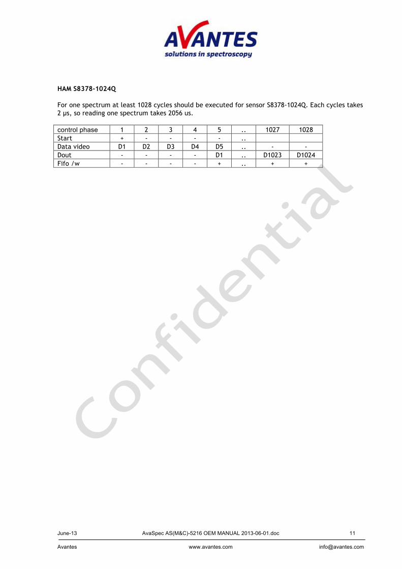
HAM S8378-1024Q
For one spectrum at least 1028 cycles should be executed for sensor S8378-1024Q. Each cycles takes 2 µs, so reading one spectrum takes 2056 us. control phase 1 2 3 4 5 .. 1027 1028 Start + - - - - .. Data video D1 D2 D3 D4 D5 .. - - Dout - - - - D1 .. D1023 D1024 Fifo /w - - - - + .. + +

June-13 AvaSpec AS(M&C)-5216 OEM MANUAL 2013-06-01.doc 12 Avantes www.avantes.com [email protected]
2.3.3 AvaBench-2048(L)-U2 ILX554B/ILX511B signals
start (rog) This signal is active low and should contain a pulse in the first cycle of reading the sensor.
clk2 This signal is active high and should contain a pulse in each cycle of reading the sensor.
Figure 3 Timing ILX554B sensor The signal clk2 is a symmetric clock, but the first phase is different. The signals cdsclk1, cdsclk2 and adcclk may run continuously. The signals start and fifo /w should only run in certain phases (see table below). For one spectrum one start cycle and at least 2088 data cycles should be executed. The start cycle takes at least 4 µs, a data cycle takes 500 ns, and so reading one spectrum takes 1.048 ms. The ILX554 is used in CDS mode. The resulting pixels after the start signal (ROG) are as follows:
2083 2084 2085 2086 2087 2088 2089 2090 Start - - - - - - - - Data video - - - Dout S2047 S2048 D33 D34 D35 D36 D37 D38 Fifo /w + + - - - - - -
control phase 1 2 3 4 5 ….. 17 18 19 ….. 32 33 Start + - - - - - - - - - Data video D1 D2 D3 D4 D5 Dout (ADC) - - - - D1 D13 D14 D15 D28 D29 Fifo /w - - - - - + + + + +
34 35 36 37 ….. 2068 2069 2070 2071 ….. 2082 Start - - - - - - - - Data video Dout D30 D31 D32 S1 S2032 S2033 S2034 S2035 S2046 Fifo /w + - - + + + + + +
June-13 AvaSpec AS(M&C)-5216 OEM MANUAL 2013-06-01.doc 13 Avantes www.avantes.com [email protected]
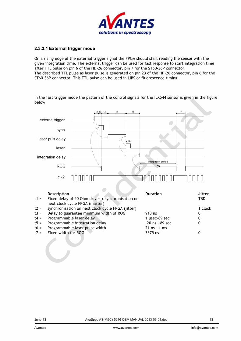
2.3.3.1 External trigger mode On a rising edge of the external trigger signal the FPGA should start reading the sensor with the given integration time. The external trigger can be used for fast response to start integration time after TTL pulse on pin 6 of the HD-26 connector, pin 7 for the ST60-36P connector. The described TTL pulse as laser pulse is generated on pin 23 of the HD-26 connector, pin 6 for the ST60-36P connector. This TTL pulse can be used in LIBS or fluorescence timing. In the fast trigger mode the pattern of the control signals for the ILX544 sensor is given in the figure below.
externe trigger
sync
laser puls delay
laser
clk2
integration delay
t1 t4t3t2
ROG
t5
S
t6
integration period
t7
Description Duration Jitter t1 = Fixed delay of 50 Ohm driver + synchronisation on
next clock cycle FPGA (master) TBD
t2 = synchronisation on next clock cycle FPGA (jitter) 1 clock t3 = Delay to guarantee minimum width of ROG 913 ns 0 t4 = Programmable laser delay 1 µsec-89 sec 0 t5 = Programmable integration delay -20 ns – 89 sec 0 t6 = Programmable laser pulse width 21 ns – 1 ms t7 = Fixed width for ROG 3375 ns 0
June-13 AvaSpec AS(M&C)-5216 OEM MANUAL 2013-06-01.doc 14 Avantes www.avantes.com [email protected]
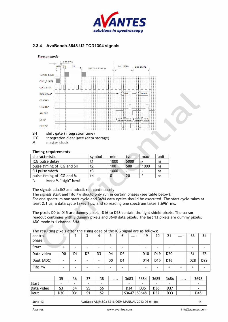
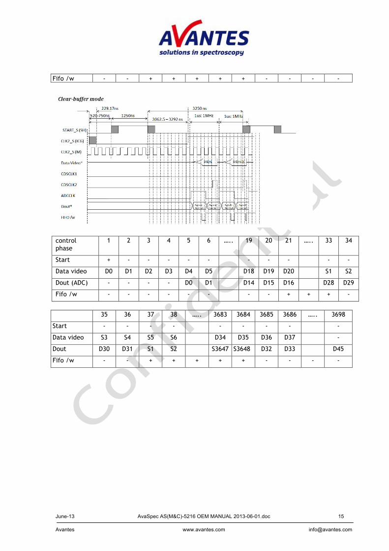
2.3.4 AvaBench-3648-U2 TCD1304 signals
SH shift gate (integration time) ICG integration clear gate (data storage) M master clock Timing requirements characteristic symbol min typ max unit ICG pulse delay t1 1000 5000 - ns pulse timing of ICG and SH t2 100 500 1000 ns SH pulse width t3 1000 - - ns pulse timing of ICG and M t4 0 20 * ns *: keep M “high” level The signals cdsclk2 and adcclk run continuously. The signals start and fifo /w should only run in certain phases (see table below). For one spectrum one start cycle and 3694 data cycles should be executed. The start cycle takes at least 2.1 µs, a data cycle takes 1 µs, and so reading one spectrum takes 3.6961 ms. The pixels D0 to D15 are dummy pixels, D16 to D28 contain the light shield pixels. The sensor readout continues with 3 dummy pixels and 3648 data pixels. The last 13 pixels are dummy pixels. ADC mode is 1 channel SHA. The resulting pixels after the rising edge of the ICG signal are as follows: control phase
1 2 3 4 5 6 ….. 19 20 21 ….. 33 34
Start + - - - - - - - - - -
Data video D0 D1 D2 D3 D4 D5 D18 D19 D20 S1 S2
Dout (ADC) - - - - D0 D1 D14 D15 D16 D28 D29
Fifo /w - - - - - - - - + + + -
35 36 37 38 ….. 3683 3684 3685 3686 ….. 3698 Start - - - - - - - - - Data video S3 S4 S5 S6 D34 D35 D36 D37 - Dout D30 D31 S1 S2 S3647 S3648 D32 D33 D45
June-13 AvaSpec AS(M&C)-5216 OEM MANUAL 2013-06-01.doc 15 Avantes www.avantes.com [email protected]
Fifo /w - - + + + + + - - - -
control phase
1 2 3 4 5 6 ….. 19 20 21 ….. 33 34
Start + - - - - - - - - - -
Data video D0 D1 D2 D3 D4 D5 D18 D19 D20 S1 S2
Dout (ADC) - - - - D0 D1 D14 D15 D16 D28 D29
Fifo /w - - - - - - - - + + + -
35 36 37 38 ….. 3683 3684 3685 3686 ….. 3698
Start - - - - - - - - -
Data video S3 S4 S5 S6 D34 D35 D36 D37 -
Dout D30 D31 S1 S2 S3647 S3648 D32 D33 D45
Fifo /w - - + + + + + - - - -
June-13 AvaSpec AS(M&C)-5216 OEM MANUAL 2013-06-01.doc 16 Avantes www.avantes.com [email protected]
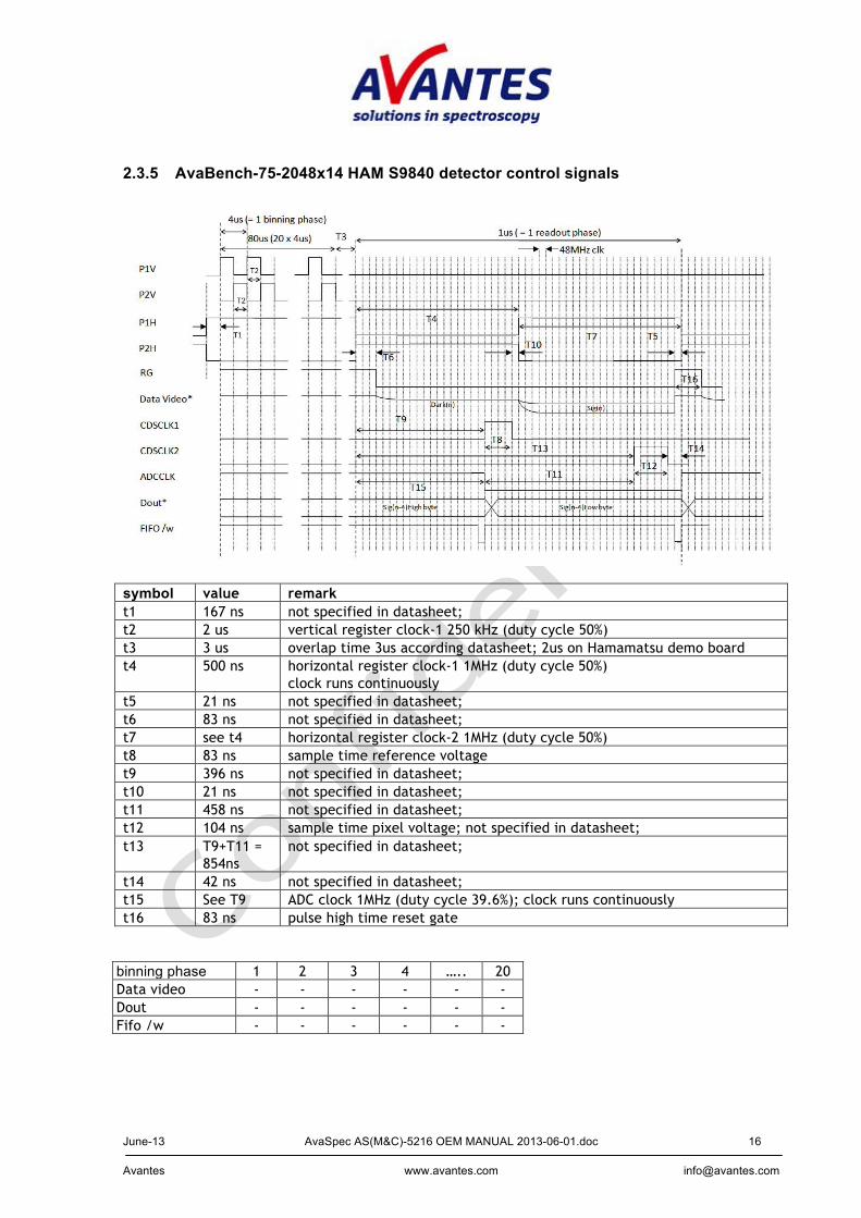
2.3.5 AvaBench-75-2048x14 HAM S9840 detector control signals
symbol value remark t1 167 ns not specified in datasheet; t2 2 us vertical register clock-1 250 kHz (duty cycle 50%) t3 3 us overlap time 3us according datasheet; 2us on Hamamatsu demo board t4 500 ns horizontal register clock-1 1MHz (duty cycle 50%)
clock runs continuously t5 21 ns not specified in datasheet; t6 83 ns not specified in datasheet; t7 see t4 horizontal register clock-2 1MHz (duty cycle 50%) t8 83 ns sample time reference voltage t9 396 ns not specified in datasheet; t10 21 ns not specified in datasheet; t11 458 ns not specified in datasheet; t12 104 ns sample time pixel voltage; not specified in datasheet; t13 T9+T11 =
854ns not specified in datasheet;
t14 42 ns not specified in datasheet; t15 See T9 ADC clock 1MHz (duty cycle 39.6%); clock runs continuously t16 83 ns pulse high time reset gate
binning phase 1 2 3 4 ….. 20 Data video - - - - - - Dout - - - - - - Fifo /w - - - - - -

June-13 AvaSpec AS(M&C)-5216 OEM MANUAL 2013-06-01.doc 17 Avantes www.avantes.com [email protected]
read out phase 1 2 3 4 5 ….. 12 ….. 16 17 18 19 Data video D1 D2 D3 D4 D5 D12 D16 S1 S2 S3 Dout (ADC) - - - - D1 D8 D12 D13 D14 D15 Fifo /w - - - - + + - - - -
read out phase 20 21 22 23 24 ….. 2067 2068 2069 2070 ….. 2084 Data video S4 S5 S6 S7 S8 Dout D16 S1 S2 S3 S4 S2047 S2048 D17 D18 D32 Fifo /w - + + + + + + - - - Total time = 2.17ms (167ns + 20 * 4us + 3us + 2084 * 1us) Notes: 1. The binning period contains 20 clock cycles. 2. The clock signals P1H_OFG, P2H_SG and ADCCLK run continuously. 3. Only the first 8 blank pixel and the 2048 signal pixels are stored in the FIFO. 4. In case there is no measurement requested the default integration time is used to control the
detector. All signals are available in default mode except RG (reset gate). There is no data stored in the FIFO. The start of a new measurement is aligned with the rising edge of P1H_OFG clock signal.
5. During evaluation of the Hamamatsu demo board different timing has been noticed for the RG, P1H_OFG and P2H_SG signals after the read out period. After the last rising edge of the RG pulse there is a delay implemented of 500 ns before the rising edge of P2H_SG and the falling edge of P1H_OFG. For now this timing difference seems to be irrelevant and is not implemented.
All sensor control signals (ccd[0..5] are inverted, because the drivers on the detector board are inverting.
June-13 AvaSpec AS(M&C)-5216 OEM MANUAL 2013-06-01.doc 18 Avantes www.avantes.com [email protected]
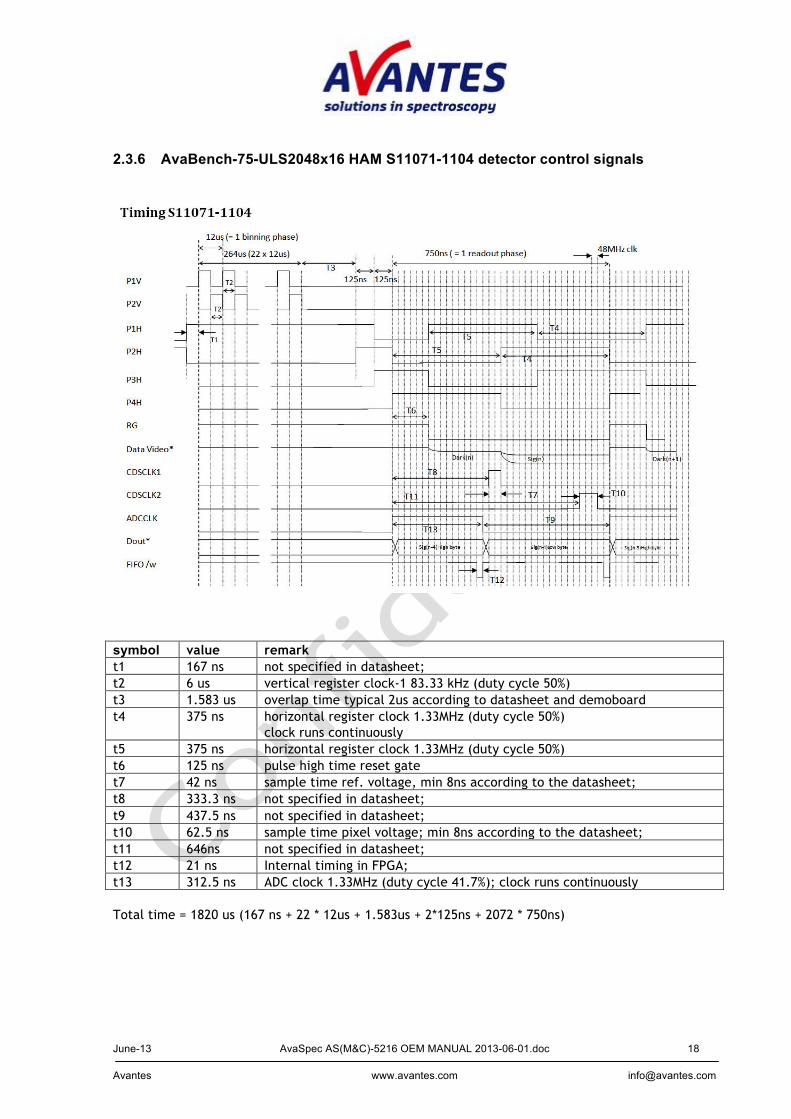
2.3.6 AvaBench-75-ULS2048x16 HAM S11071-1104 detector control signals
symbol value remark t1 167 ns not specified in datasheet; t2 6 us vertical register clock-1 83.33 kHz (duty cycle 50%) t3 1.583 us overlap time typical 2us according to datasheet and demoboard t4 375 ns horizontal register clock 1.33MHz (duty cycle 50%)
clock runs continuously t5 375 ns horizontal register clock 1.33MHz (duty cycle 50%) t6 125 ns pulse high time reset gate t7 42 ns sample time ref. voltage, min 8ns according to the datasheet; t8 333.3 ns not specified in datasheet; t9 437.5 ns not specified in datasheet; t10 62.5 ns sample time pixel voltage; min 8ns according to the datasheet; t11 646ns not specified in datasheet; t12 21 ns Internal timing in FPGA; t13 312.5 ns ADC clock 1.33MHz (duty cycle 41.7%); clock runs continuously Total time = 1820 us (167 ns + 22 * 12us + 1.583us + 2*125ns + 2072 * 750ns)

June-13 AvaSpec AS(M&C)-5216 OEM MANUAL 2013-06-01.doc 19 Avantes www.avantes.com [email protected]
binning phase 1 2 3 4 ….. 22 Data video - - - - - - Dout - - - - - - Fifo /w - - - - - -
read out phase 1 2 3 4 5 ….. 8 9 ….. 13 14 15 16 Data video D1 D2 D3 D4 D5 D8 S9 S3 S4 S5 S6 Dout (ADC) - - - - D1 D4 D5 D9 D10 S1 S2 Fifo /w - - - - + + - - - + +
read out phase 17 18 19 …. 2057 2058 2059 2060 2061 2062 2063 ….. 2072 Data video S7 S8 S9 S2047 S2048 D11 D12 D13 D14 D15 Dout S3 S4 S5 S2043 S2044 S2045 S2046 S2047 S2048 D11 D20 Fifo /w + + + + + + + + + - -
June-13 AvaSpec AS(M&C)-5216 OEM MANUAL 2013-06-01.doc 20 Avantes www.avantes.com [email protected]
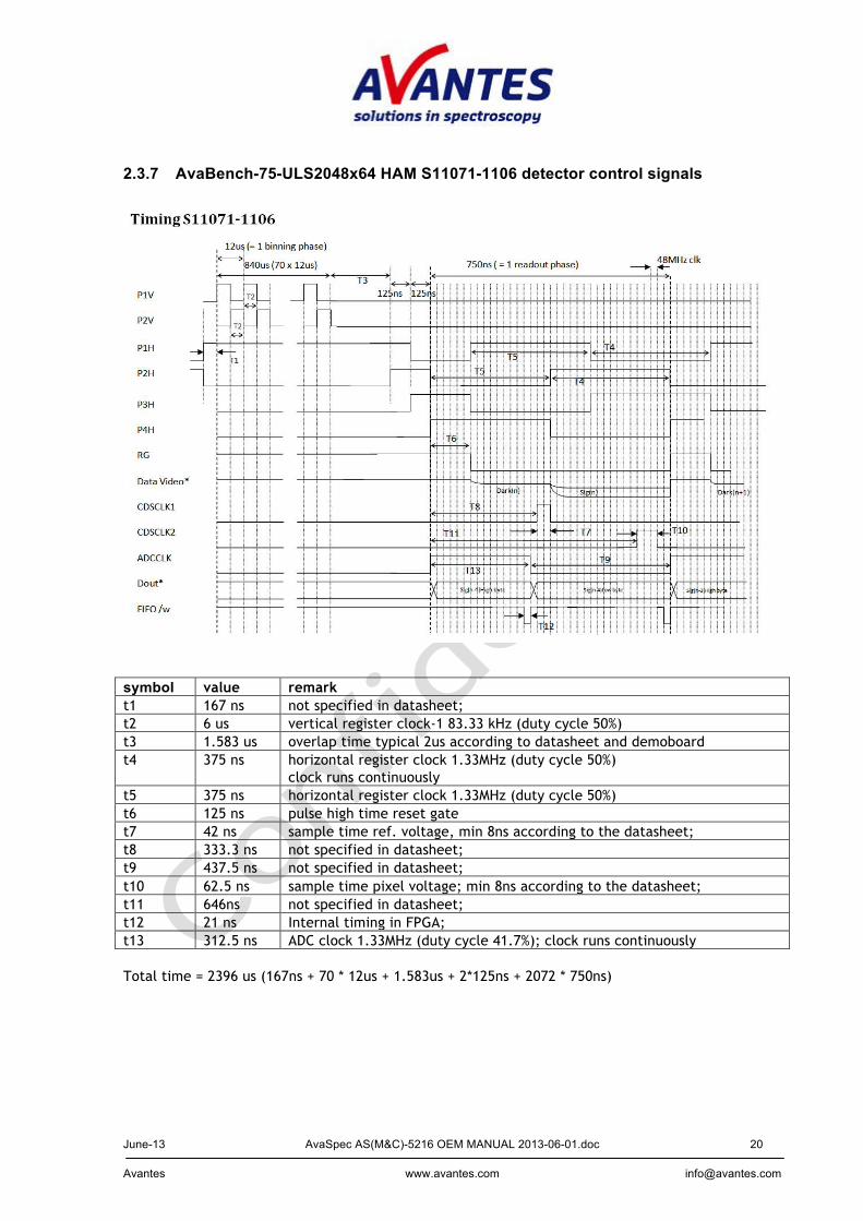
2.3.7 AvaBench-75-ULS2048x64 HAM S11071-1106 detector control signals
symbol value remark t1 167 ns not specified in datasheet; t2 6 us vertical register clock-1 83.33 kHz (duty cycle 50%) t3 1.583 us overlap time typical 2us according to datasheet and demoboard t4 375 ns horizontal register clock 1.33MHz (duty cycle 50%)
clock runs continuously t5 375 ns horizontal register clock 1.33MHz (duty cycle 50%) t6 125 ns pulse high time reset gate t7 42 ns sample time ref. voltage, min 8ns according to the datasheet; t8 333.3 ns not specified in datasheet; t9 437.5 ns not specified in datasheet; t10 62.5 ns sample time pixel voltage; min 8ns according to the datasheet; t11 646ns not specified in datasheet; t12 21 ns Internal timing in FPGA; t13 312.5 ns ADC clock 1.33MHz (duty cycle 41.7%); clock runs continuously Total time = 2396 us (167ns + 70 * 12us + 1.583us + 2*125ns + 2072 * 750ns)
June-13 AvaSpec AS(M&C)-5216 OEM MANUAL 2013-06-01.doc 21 Avantes www.avantes.com [email protected]
binning phase 1 2 3 4 ….. 70 Data video - - - - - - Dout - - - - - - Fifo /w - - - - - -
read out phase 1 2 3 4 5 ….. 8 9 ….. 13 14 15 16 Data video D1 D2 D3 D4 D5 D8 S9 S3 S4 S5 S6 Dout (ADC) - - - - D1 D4 D5 D9 D10 S1 S2 Fifo /w - - - - + + - - - + +
read out phase 17 18 19 …. 2057 2058 2059 2060 2061 2062 2063 ….. 2072 Data video S7 S8 S9 S2047 S2048 D11 D12 D13 D14 D15 Dout S3 S4 S5 S2043 S2044 S2045 S2046 S2047 S2048 D11 D20 Fifo /w + + + + + + + + + - -
June-13 AvaSpec AS(M&C)-5216 OEM MANUAL 2013-06-01.doc 22 Avantes www.avantes.com [email protected]
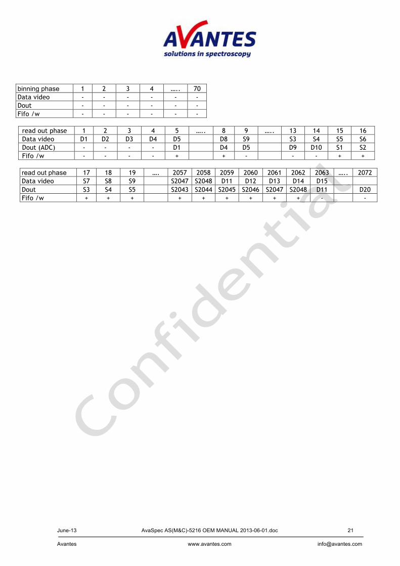
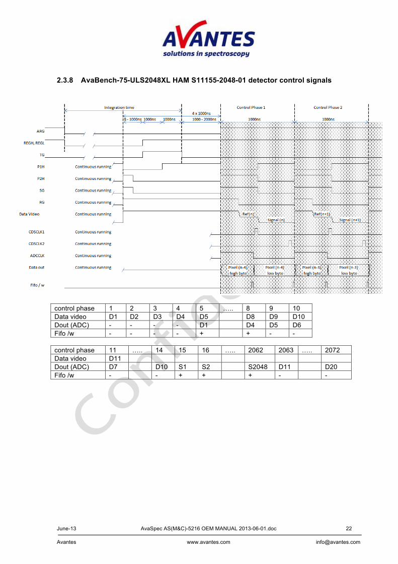
2.3.8 AvaBench-75-ULS2048XL HAM S11155-2048-01 detector control signals
control phase 1 2 3 4 5 ….. 8 9 10 Data video D1 D2 D3 D4 D5 D8 D9 D10 Dout (ADC) - - - - D1 D4 D5 D6 Fifo /w - - - - + + - -
control phase 11 ….. 14 15 16 ….. 2062 2063 ….. 2072 Data video D11 Dout (ADC) D7 D10 S1 S2 S2048 D11 D20 Fifo /w - - + + + - -
June-13 AvaSpec AS(M&C)-5216 OEM MANUAL 2013-06-01.doc 23 Avantes www.avantes.com [email protected]
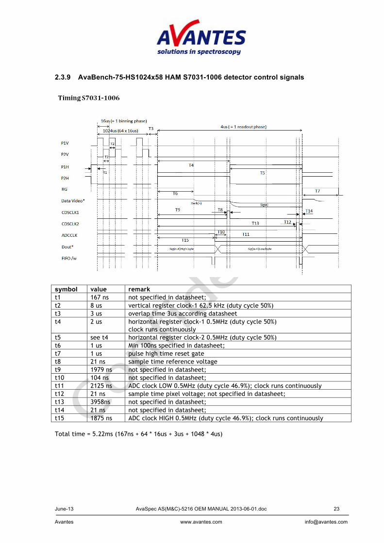
2.3.9 AvaBench-75-HS1024x58 HAM S7031-1006 detector control signals
symbol value remark t1 167 ns not specified in datasheet; t2 8 us vertical register clock-1 62.5 kHz (duty cycle 50%) t3 3 us overlap time 3us according datasheet t4 2 us horizontal register clock-1 0.5MHz (duty cycle 50%)
clock runs continuously t5 see t4 horizontal register clock-2 0.5MHz (duty cycle 50%) t6 1 us Min 100ns specified in datasheet; t7 1 us pulse high time reset gate t8 21 ns sample time reference voltage t9 1979 ns not specified in datasheet; t10 104 ns not specified in datasheet; t11 2125 ns ADC clock LOW 0.5MHz (duty cycle 46.9%); clock runs continuously t12 21 ns sample time pixel voltage; not specified in datasheet; t13 3958ns not specified in datasheet; t14 21 ns not specified in datasheet; t15 1875 ns ADC clock HIGH 0.5MHz (duty cycle 46.9%); clock runs continuously Total time = 5.22ms (167ns + 64 * 16us + 3us + 1048 * 4us)

June-13 AvaSpec AS(M&C)-5216 OEM MANUAL 2013-06-01.doc 24 Avantes www.avantes.com [email protected]
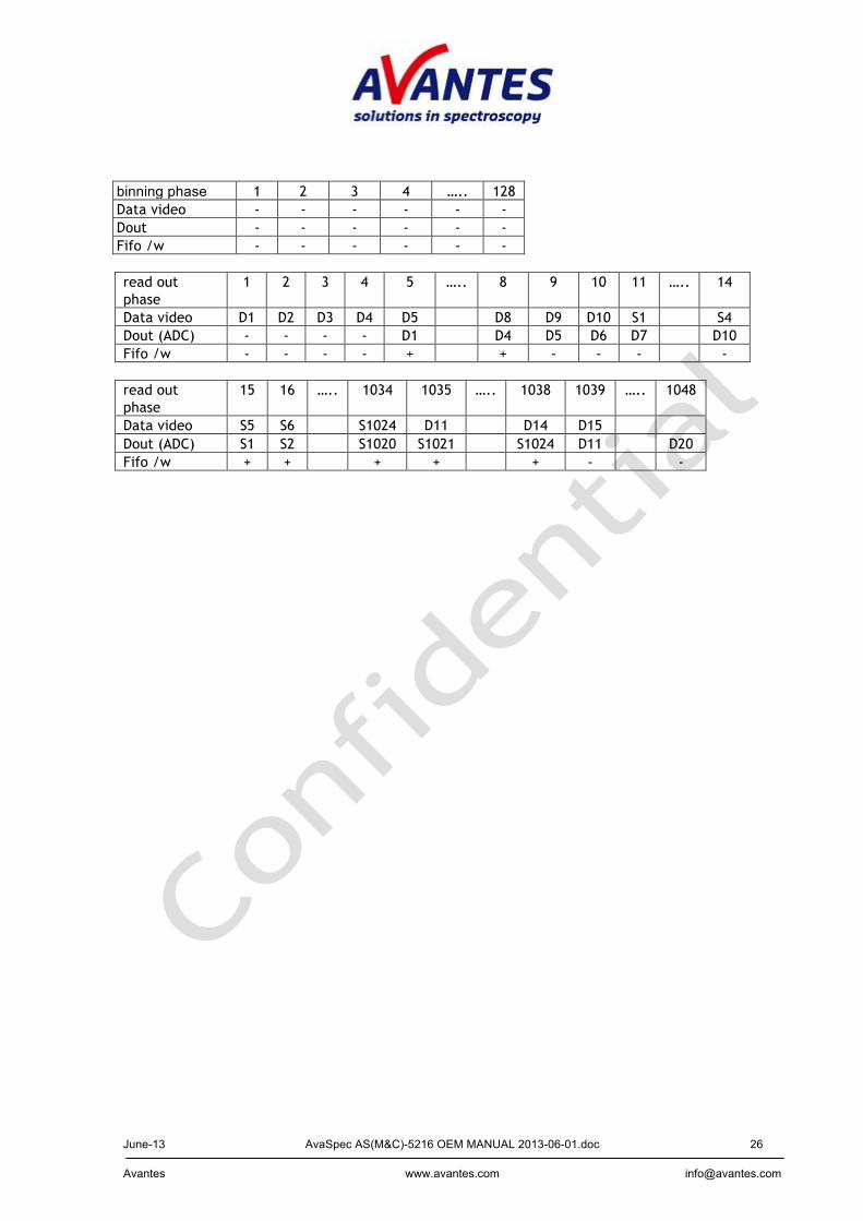
binning phase 1 2 3 4 ….. 64 Data video - - - - - - Dout - - - - - - Fifo /w - - - - - - read out phase
1 2 3 4 5 ….. 8 9 10 11 ….. 14
Data video D1 D2 D3 D4 D5 D8 D9 D10 S1 S4 Dout (ADC) - - - - D1 D4 D5 D6 D7 D10 Fifo /w - - - - + + - - - - read out phase
15 16 ….. 1034 1035 ….. 1038 1039 ….. 1048
Data video S5 S6 S1024 D11 D14 D15 Dout (ADC) S1 S2 S1020 S1021 S1024 D11 D20 Fifo /w + + + + + - -

June-13 AvaSpec AS(M&C)-5216 OEM MANUAL 2013-06-01.doc 25 Avantes www.avantes.com [email protected]
2.3.10 AvaBench-75-HS1024x122 HAM S7031-1007 detector control signals
symbol value remark t1 167 ns not specified in datasheet; t2 8 us vertical register clock-1 62.5 kHz (duty cycle 50%) t3 3 us overlap time 3us according datasheet t4 2 us horizontal register clock-1 0.5MHz (duty cycle 50%)
clock runs continuously t5 see t4 horizontal register clock-2 0.5MHz (duty cycle 50%) t6 1 us Min 100ns specified in datasheet; t7 1 us pulse high time reset gate t8 21 ns sample time reference voltage t9 1979 ns not specified in datasheet; t10 104 ns not specified in datasheet; t11 2125 ns ADC clock LOW 0.5MHz (duty cycle 46.9%); clock runs continuously t12 21 ns sample time pixel voltage; not specified in datasheet; t13 3958ns not specified in datasheet; t14 21 ns not specified in datasheet; t15 1875 ns ADC clock HIGH 0.5MHz (duty cycle 46.9%); clock runs continuously
June-13 AvaSpec AS(M&C)-5216 OEM MANUAL 2013-06-01.doc 26 Avantes www.avantes.com [email protected]
binning phase 1 2 3 4 ….. 128 Data video - - - - - - Dout - - - - - - Fifo /w - - - - - - read out phase
1 2 3 4 5 ….. 8 9 10 11 ….. 14
Data video D1 D2 D3 D4 D5 D8 D9 D10 S1 S4 Dout (ADC) - - - - D1 D4 D5 D6 D7 D10 Fifo /w - - - - + + - - - - read out phase
15 16 ….. 1034 1035 ….. 1038 1039 ….. 1048
Data video S5 S6 S1024 D11 D14 D15 Dout (ADC) S1 S2 S1020 S1021 S1024 D11 D20 Fifo /w + + + + + - -
June-13 AvaSpec AS(M&C)-5216 OEM MANUAL 2013-06-01.doc 27 Avantes www.avantes.com [email protected]
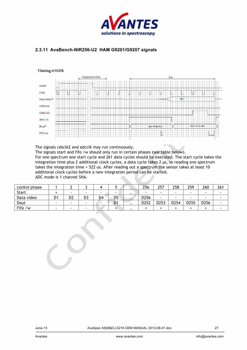
2.3.11 AvaBench-NIR256-U2 HAM G9201/G9207 signals
The signals cdsclk2 and adcclk may run continuously. The signals start and fifo /w should only run in certain phases (see table below). For one spectrum one start cycle and 261 data cycles should be executed. The start cycle takes the integration time plus 2 additional clock cycles, a data cycle takes 2 µs, so reading one spectrum takes the integration time + 522 us. After reading out a spectrum the sensor takes at least 10 additional clock cycles before a new integration period can be started. ADC mode is 1 channel SHA.
control phase 1 2 3 4 5 .. 256 257 258 259 260 261 Start + - - - - .. - - - - - - Data video D1 D2 D3 D4 D5 .. D256 - - - - - Dout - - - - D1 .. D252 D253 D254 D255 D256 - Fifo /w - - - - + .. + + + + + -
June-13 AvaSpec AS(M&C)-5216 OEM MANUAL 2013-06-01.doc 28 Avantes www.avantes.com [email protected]
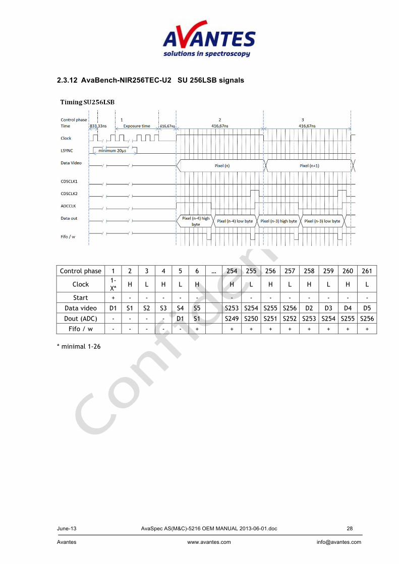
2.3.12 AvaBench-NIR256TEC-U2 SU 256LSB signals
Control phase 1 2 3 4 5 6 … 254 255 256 257 258 259 260 261
Clock 1-X*
H L H L H
H L H L H L H L
Start + - - - - -
- - - - - - - -
Data video D1 S1 S2 S3 S4 S5
S253 S254 S255 S256 D2 D3 D4 D5
Dout (ADC) - - - - D1 S1
S249 S250 S251 S252 S253 S254 S255 S256
Fifo / w - - - - - +
+ + + + + + + + * minimal 1-26
June-13 AvaSpec AS(M&C)-5216 OEM MANUAL 2013-06-01.doc 29 Avantes www.avantes.com [email protected]
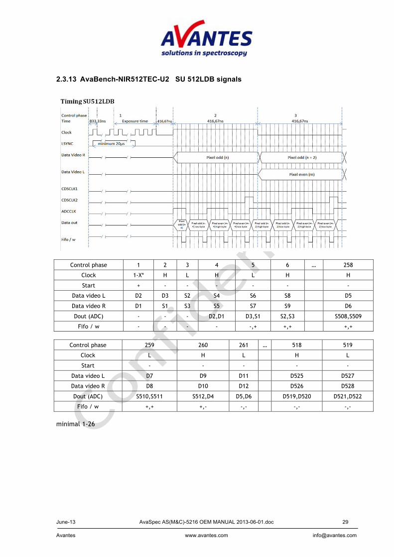
2.3.13 AvaBench-NIR512TEC-U2 SU 512LDB signals
Control phase 1 2 3 4 5 6 … 258
Clock 1-X* H L H L H
H
Start + - - - - -
-
Data video L D2 D3 S2 S4 S6 S8
D5
Data video R D1 S1 S3 S5 S7 S9
D6
Dout (ADC) - - - D2,D1 D3,S1 S2,S3
S508,S509
Fifo / w - - - - -,+ +,+
+,+
Control phase 259 260 261 … 518 519
Clock L H L H L
Start - - - - -
Data video L D7 D9 D11 D525 D527
Data video R D8 D10 D12 D526 D528
Dout (ADC) S510,S511 S512,D4 D5,D6 D519,D520 D521,D522
Fifo / w +,+ +,- -,- -,- -,-
minimal 1-26

June-13 AvaSpec AS(M&C)-5216 OEM MANUAL 2013-06-01.doc 30 Avantes www.avantes.com [email protected]
2.4 Interface Design AvaSpec RS232/USB interface
Interface overview The spectrometer provides a serial connection with a PC using RS232 or USB. Avantes recommends Windows users to use the Dynamic Linking Library (DLL) package; the functions are described in the separate AS-5216 DLL manual. An enhanced binary datalink protocol is used for RS232 communication between spectrometer and the DLL. The datalink protocol implements an application protocol. This protocol is equal for RS232 and USB. The protocol contains a message-sequence number to provide synchronization and identification. The RS232 communication relation is always master (PC) and slave (spectrometer). The spectrometer will always respond to a request from the PC. Physical Interface The following RS232 settings are used: Setting Value Baudrate 115200 Databits 8 Startbits 1 StopBits 1 Parity None Handshaking None Datalink layer Binary coding and control sequences The enhanced protocol is binary coded. For RS232, control sequences are used to mark the begin and end of a message in the byte stream. A control sequence starts with a DLE byte (0x10) and is followed by a control byte. The following control sequences are defined: Table of RS232 datalink control sequences: First byte Second byte Function DLE (0x10) STX (0x02) Start of message DLE (0x10) ETX (0x03) End of message DLE (0x10) DLE (0x10) Data byte 0x10 DLE (0x10) any other
character Not allowed. Messages that contain such a sequence will be ignored. The receiver waits for a new DLE STX sequence.
The [DLE DLE] sequence is used to prevent possible DLE bytes in the transmitted binary data stream from being recognized as the start of a control sequence. The sender replaces any DLE bytes in the data by two DLE bytes. The datalink of the receiver will convert a [DLE DLE] sequences to one DLE byte. The USB protocol does not include the DLE sequences. Note: If a RS232 error (receiver overrun, framing error, not allowed control sequence) occurs, the
datalink frame is ignored.

June-13 AvaSpec AS(M&C)-5216 OEM MANUAL 2013-06-01.doc 31 Avantes www.avantes.com [email protected]
Message Layout
Request from PC to Spectrometer The enhanced binary coded messages between PC and Spectrometer are structured as follows (each field denotes a byte value:
DLE STX type seq len_lsb
len_msb
... data ... DLE ETX
DLE, STX start sequence type 0x20 seq message sequence number len_lsb least significant byte of length of data field in bytes len_msb most significant byte of length of data field in bytes data message field DLE, ETX end sequence
Response from Spectrometer to PC The responses from the spectrometer to the PC have the same message format as the request An error message has a special format:
DLE STX type seq 0x00 0x00 error DLE ETX DLE, STX start sequence type 0x20 seq message sequence number, as in request error error code DLE, ETX end sequence
DataMsg from Spectrometer to PC The unsollicited data messages from the spectrometer to the PC have the same message format as the requested messages, only the type field is fixed to 0x21. The sequence number is generated and incremented by the spectrometer. Data Elements The error code can have the following values: Table 1 RS232 datalink error codes Value Meaning 3 Message rejected by spectrometer, receiver buffer overflow 5 Spectrometer communication error: timeout or message rejected 8 Time out during sending 9 No response on a request received within time out Communication Procedures The enhanced protocol allows the transmission of more than one request at a time. The sequence number makes it possible to associate the answer with the according request. The spectrometer has more than one message buffer where messages may be stored (typically 5). When the message buffers are full, the spectrometer responds with an error message. Application Layer Message Layout

June-13 AvaSpec AS(M&C)-5216 OEM MANUAL 2013-06-01.doc 32 Avantes www.avantes.com [email protected]
The message field in the enhanced binary protocol is filled with the application protocol data. The application protocol is relatively simple. The following format depicts the protocol: command_id +reserved_field+ command_specific_parameters Note 1: The reserved field is used to start the command specific parameters at a word aligned
offset. Note 2: Numbers which are larger than a single byte are sent with the most significant byte (MSB)
first. Note 3: Floating point numbers are single precision according to the IEEE 754. The MSB is the first
byte, the LSB the last. Note 4: All structures are byte aligned.
Request from PC to Spectrometer The following commands are valid from PC to spectrometer: Table 2 Application commands PC to AS5216 Command Command
Id (hex) Parameters Description
get_device_configuration 0x01 None Request from PC to spectrometer to send the device configuration structure.
set_device_- configuration
0x02 ConfigData Request from PC to overwrite the device configuration structure
prepare_measurement 0x05 MeasConfigData Request from PC to spectrometer to prepare a measurement with the specified configuration
start_measurement 0x06 Nmsr Request from PC to spectrometer to start measurement and send measurement data in response.
get_stored_meas 0x07 - Request to send measurement data of first unread measurement in RAM
get_avg_stored_meas 0x08 - Request to send averaged measurement data of first unread averaged measurement in RAM
set_SD_card 0x09 SDConfigData Request to overwrite SD configuration data (enable/disable writing spectra to SD card)
get_digital_in 0x0A InputId Request to send status of the specified digital input
set_digital_output 0x0B OutputId, OutputValue
Request to set the specified digital output
get_analog_in 0x0C AnInputId Request to send status of the specified analog input
June-13 AvaSpec AS(M&C)-5216 OEM MANUAL 2013-06-01.doc 33 Avantes www.avantes.com [email protected]
Command Command Id (hex)
Parameters Description
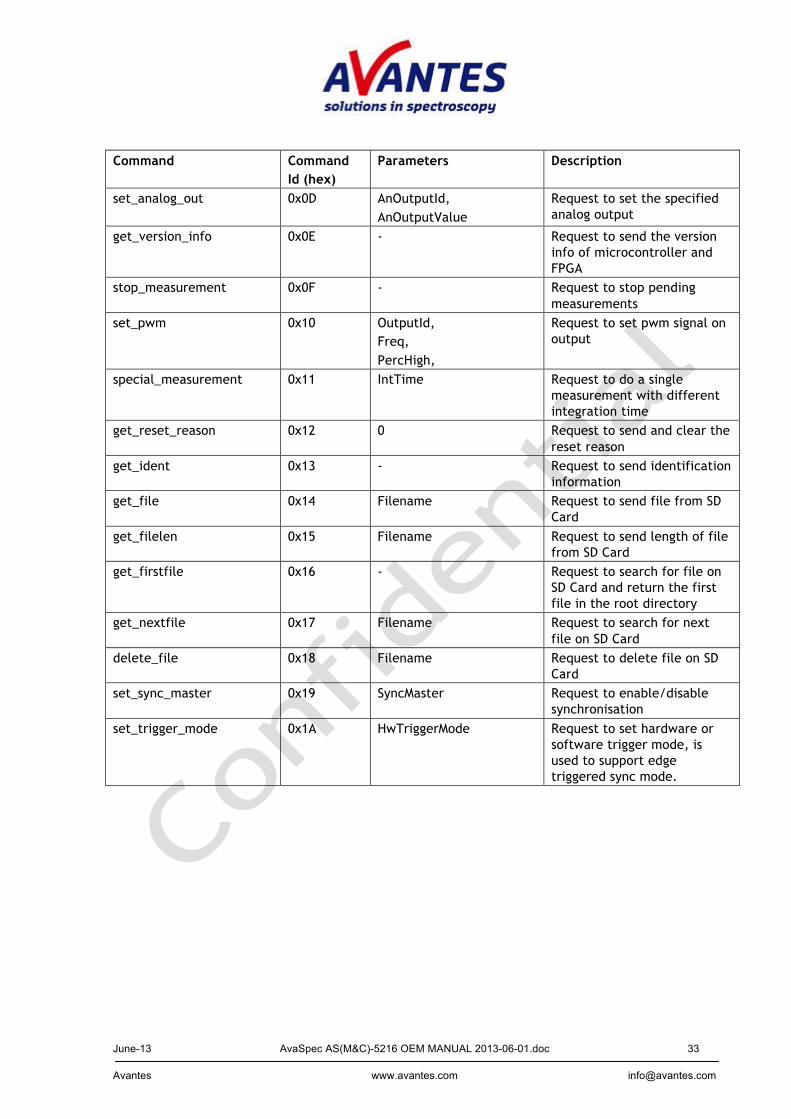
set_analog_out 0x0D AnOutputId, AnOutputValue
Request to set the specified analog output
get_version_info 0x0E - Request to send the version info of microcontroller and FPGA
stop_measurement 0x0F - Request to stop pending measurements
set_pwm 0x10 OutputId, Freq, PercHigh,
Request to set pwm signal on output
special_measurement 0x11 IntTime Request to do a single measurement with different integration time
get_reset_reason 0x12 0 Request to send and clear the reset reason
get_ident 0x13 - Request to send identification information
get_file 0x14 Filename Request to send file from SD Card
get_filelen 0x15 Filename Request to send length of file from SD Card
get_firstfile 0x16 - Request to search for file on SD Card and return the first file in the root directory
get_nextfile 0x17 Filename Request to search for next file on SD Card
delete_file 0x18 Filename Request to delete file on SD Card
set_sync_master 0x19 SyncMaster Request to enable/disable synchronisation
set_trigger_mode 0x1A HwTriggerMode Request to set hardware or software trigger mode, is used to support edge triggered sync mode.
June-13 AvaSpec AS(M&C)-5216 OEM MANUAL 2013-06-01.doc 34 Avantes www.avantes.com [email protected]
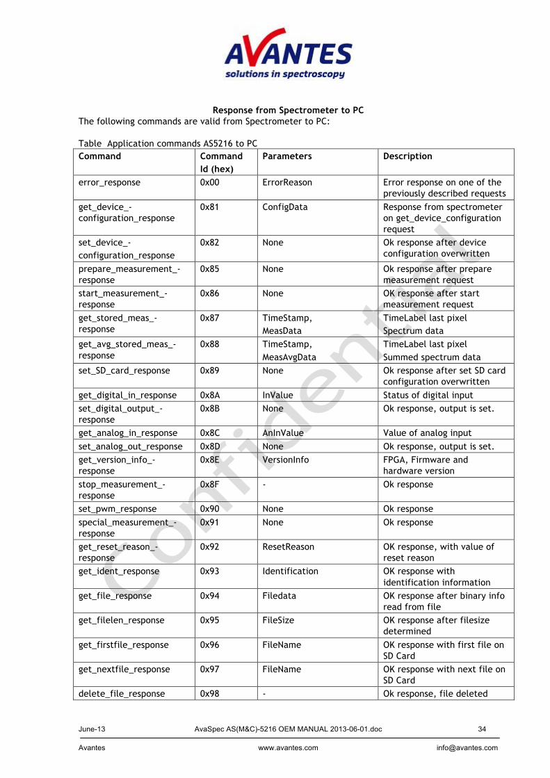
Response from Spectrometer to PC The following commands are valid from Spectrometer to PC: Table Application commands AS5216 to PC Command Command
Id (hex) Parameters Description
error_response 0x00 ErrorReason Error response on one of the previously described requests
get_device_-configuration_response
0x81 ConfigData Response from spectrometer on get_device_configuration request
set_device_- configuration_response
0x82 None Ok response after device configuration overwritten
prepare_measurement_-response
0x85 None Ok response after prepare measurement request
start_measurement_-response
0x86 None OK response after start measurement request
get_stored_meas_-response
0x87 TimeStamp, MeasData
TimeLabel last pixel Spectrum data
get_avg_stored_meas_-response
0x88 TimeStamp, MeasAvgData
TimeLabel last pixel Summed spectrum data
set_SD_card_response 0x89 None Ok response after set SD card configuration overwritten
get_digital_in_response 0x8A InValue Status of digital input set_digital_output_-response
0x8B None Ok response, output is set.
get_analog_in_response 0x8C AnInValue Value of analog input set_analog_out_response 0x8D None Ok response, output is set. get_version_info_-response
0x8E VersionInfo FPGA, Firmware and hardware version
stop_measurement_-response
0x8F - Ok response
set_pwm_response 0x90 None Ok response special_measurement_-response
0x91 None Ok response
get_reset_reason_-response
0x92 ResetReason OK response, with value of reset reason
get_ident_response 0x93 Identification OK response with identification information
get_file_response 0x94 Filedata OK response after binary info read from file
get_filelen_response 0x95 FileSize OK response after filesize determined
get_firstfile_response 0x96 FileName OK response with first file on SD Card
get_nextfile_response 0x97 FileName OK response with next file on SD Card
delete_file_response 0x98 - Ok response, file deleted
June-13 AvaSpec AS(M&C)-5216 OEM MANUAL 2013-06-01.doc 35 Avantes www.avantes.com [email protected]
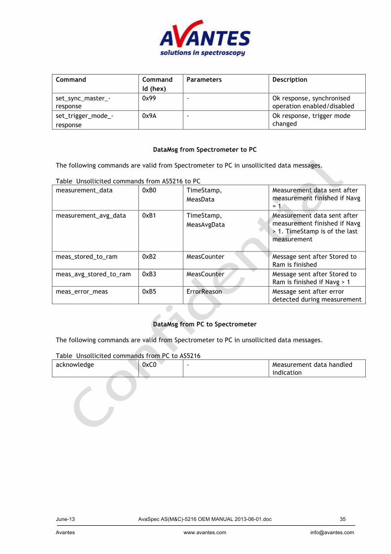
Command Command Id (hex)
Parameters Description
set_sync_master_-response
0x99 - Ok response, synchronised operation enabled/disabled
set_trigger_mode_- response
0x9A - Ok response, trigger mode changed
DataMsg from Spectrometer to PC The following commands are valid from Spectrometer to PC in unsollicited data messages. Table Unsollicited commands from AS5216 to PC measurement_data 0xB0 TimeStamp,
MeasData Measurement data sent after measurement finished if Navg = 1
measurement_avg_data 0xB1 TimeStamp, MeasAvgData
Measurement data sent after measurement finished if Navg > 1. TimeStamp is of the last measurement
meas_stored_to_ram 0xB2 MeasCounter Message sent after Stored to Ram is finished
meas_avg_stored_to_ram 0xB3 MeasCounter Message sent after Stored to Ram is finished if Navg > 1
meas_error_meas 0xB5 ErrorReason Message sent after error detected during measurement
DataMsg from PC to Spectrometer The following commands are valid from Spectrometer to PC in unsollicited data messages. Table Unsollicited commands from PC to AS5216 acknowledge 0xC0 - Measurement data handled
indication
June-13 AvaSpec AS(M&C)-5216 OEM MANUAL 2013-06-01.doc 36 Avantes www.avantes.com [email protected]
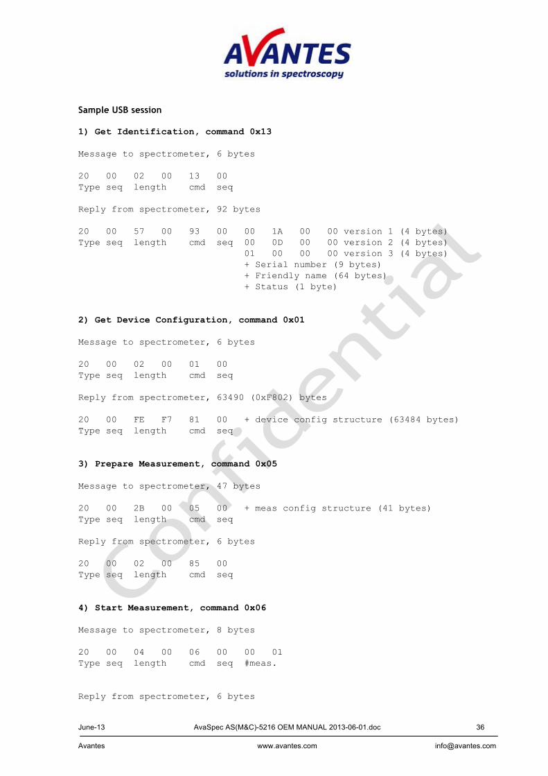
Sample USB session 1) Get Identification, command 0x13 Message to spectrometer, 6 bytes 20 00 02 00 13 00 Type seq length cmd seq
Reply from spectrometer, 92 bytes 20 00 57 00 93 00 00 1A 00 00 version 1 (4 bytes) Type seq length cmd seq 00 0D 00 00 version 2 (4 bytes) 01 00 00 00 version 3 (4 bytes) + Serial number (9 bytes) + Friendly name (64 bytes) + Status (1 byte) 2) Get Device Configuration, command 0x01 Message to spectrometer, 6 bytes 20 00 02 00 01 00 Type seq length cmd seq Reply from spectrometer, 63490 (0xF802) bytes 20 00 FE F7 81 00 + device config structure (63484 bytes) Type seq length cmd seq 3) Prepare Measurement, command 0x05 Message to spectrometer, 47 bytes 20 00 2B 00 05 00 + meas config structure (41 bytes) Type seq length cmd seq Reply from spectrometer, 6 bytes 20 00 02 00 85 00 Type seq length cmd seq 4) Start Measurement, command 0x06 Message to spectrometer, 8 bytes 20 00 04 00 06 00 00 01 Type seq length cmd seq #meas. Reply from spectrometer, 6 bytes

June-13 AvaSpec AS(M&C)-5216 OEM MANUAL 2013-06-01.doc 37 Avantes www.avantes.com [email protected]
20 00 02 00 86 00 Type seq length cmd seq
June-13 AvaSpec AS(M&C)-5216 OEM MANUAL 2013-06-01.doc 38 Avantes www.avantes.com [email protected]
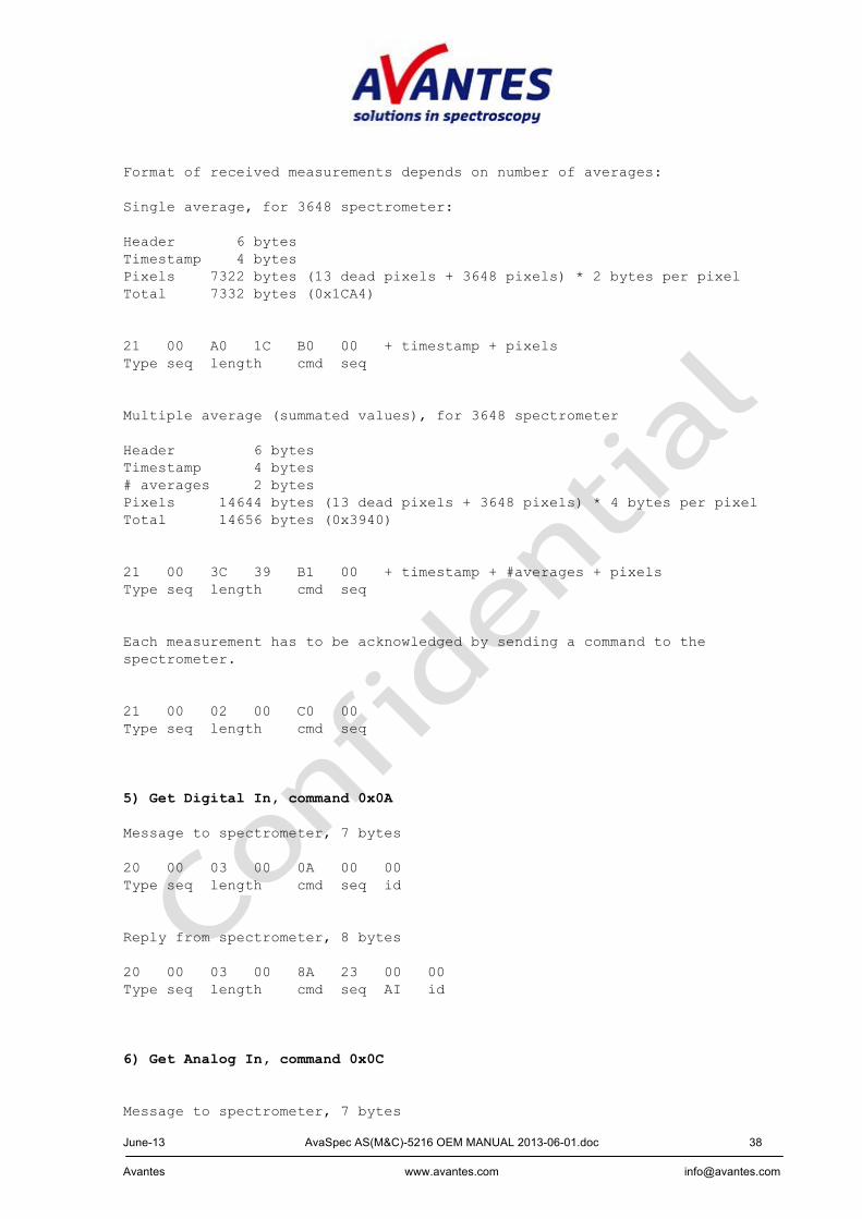
Format of received measurements depends on number of averages: Single average, for 3648 spectrometer: Header 6 bytes Timestamp 4 bytes Pixels 7322 bytes (13 dead pixels + 3648 pixels) * 2 bytes per pixel Total 7332 bytes (0x1CA4) 21 00 A0 1C B0 00 + timestamp + pixels Type seq length cmd seq Multiple average (summated values), for 3648 spectrometer Header 6 bytes Timestamp 4 bytes # averages 2 bytes Pixels 14644 bytes (13 dead pixels + 3648 pixels) * 4 bytes per pixel Total 14656 bytes (0x3940) 21 00 3C 39 B1 00 + timestamp + #averages + pixels Type seq length cmd seq Each measurement has to be acknowledged by sending a command to the spectrometer. 21 00 02 00 C0 00 Type seq length cmd seq 5) Get Digital In, command 0x0A Message to spectrometer, 7 bytes 20 00 03 00 0A 00 00 Type seq length cmd seq id Reply from spectrometer, 8 bytes 20 00 03 00 8A 23 00 00 Type seq length cmd seq AI id 6) Get Analog In, command 0x0C Message to spectrometer, 7 bytes
June-13 AvaSpec AS(M&C)-5216 OEM MANUAL 2013-06-01.doc 39 Avantes www.avantes.com [email protected]
20 00 03 00 0C 00 00 Type seq length cmd seq id

June-13 AvaSpec AS(M&C)-5216 OEM MANUAL 2013-06-01.doc 40 Avantes www.avantes.com [email protected]
Reply from spectrometer, 8 bytes 20 00 04 00 8C 00 13 88 Type seq length cmd seq analog in 0x1388 = 5000 = 5.0 Volts 7) Set Analog Out, command 0x0D Message to spectrometer, 9 bytes 20 00 05 00 0D 00 00 01 2C Type seq length cmd seq id analog out (0x012C = 300 = 3.0 Volts) Reply from spectrometer, 6 bytes 20 00 02 00 8D 00 Type seq length cmd seq 8) Set Digital Out, command 0x0B Message to spectrometer, 8 bytes 20 00 04 00 0B 00 04 01 Type seq length cmd seq id DO Reply from spectrometer, 6 bytes 20 00 02 00 8B 00 Type seq length cmd seq 9) Set PWM, command 0x10 Message to spectrometer, 12 bytes 20 44 08 00 10 00 00 00 00 03 E8 32 Type seq length cmd seq id frequency duty (0x000003E8 = 1000 Hz, 0x32 = 50 % duty cycle) Reply from spectrometer, 6 bytes 20 00 02 00 90 00 Type seq length cmd seq
June-13 AvaSpec AS(M&C)-5216 OEM MANUAL 2013-06-01.doc 41 Avantes www.avantes.com [email protected]
Sample StoreToRam USB session 1) Prepare Measurement, command 0x05 See above, measurement configuration structure must contain a number > 0 in the StoreToRam field. 2) Start Measurement, command 0x06 See above, number of measurements here equals the number of StoreToRam measurements. N.B. When using the AS5216 DLL, the number of measurements in the AVS_Measure call must be equal to 1 in this case !! The measurement data that the spectrometer returns now are 10 bytes long: 21 00 06 00 B2 1D 00 00 01 2C Type seq length cmd seq measurements (0x0000012C = 300 measurements, seq number equals the one from the previous Start Measurement call) Next, these measurements can be read from the spectrometer with a command each: 3) Get Stored Measurement, command 0x07 Message to the spectrometer, 6 bytes 20 00 02 00 07 00 Type seq length cmd seq Reply from the spectrometer, length depends on detector and number of averages, e.g. single average, for 3648 spectrometer: Header 6 bytes Timestamp 4 bytes Pixels 7322 bytes (13 dead pixels + 3648 pixels) * 2 bytes per pixel Total 7332 bytes (0x1CA4) 20 00 A0 1C 87 00 + timestamp + pixels Type seq length cmd seq Data elements structures See Appendix A.

June-13 AvaSpec AS(M&C)-5216 OEM MANUAL 2013-06-01.doc 42 Avantes www.avantes.com [email protected]
2.5 AS-5216 Electronics Hardware interfaces The AS5216 is the next generation spectrometer board of Avantes. It is the successor of the AS161. The AS5216 controls data acquisition of several types of spectrometers, and handles data transfer to the end user over RS-232, Bluetooth, and USB2.0 or saves the data on an SD-Card. The AS5216 provides interfaces to laser and strobe bulb. Multiple boards can be synchronized, in order to create many spectra at the same time.
AS5216
PC
Optical block
USB 2.0
RS232
Bluetooth
stro
bopu
lse
Lase
rpul
se
Trig
ger s
tart
SD-CardSync w. other boards
Features within dashed line available on AS5216BT only
LED´s
USB2
Synch
HD-26
SD-card optional
12p picoflex to AvaBench detector
Coax video To AvaBench
detector
12VDC
Bluetooth transmitter
Power jumper
June-13 AvaSpec AS(M&C)-5216 OEM MANUAL 2013-06-01.doc 43 Avantes www.avantes.com [email protected]
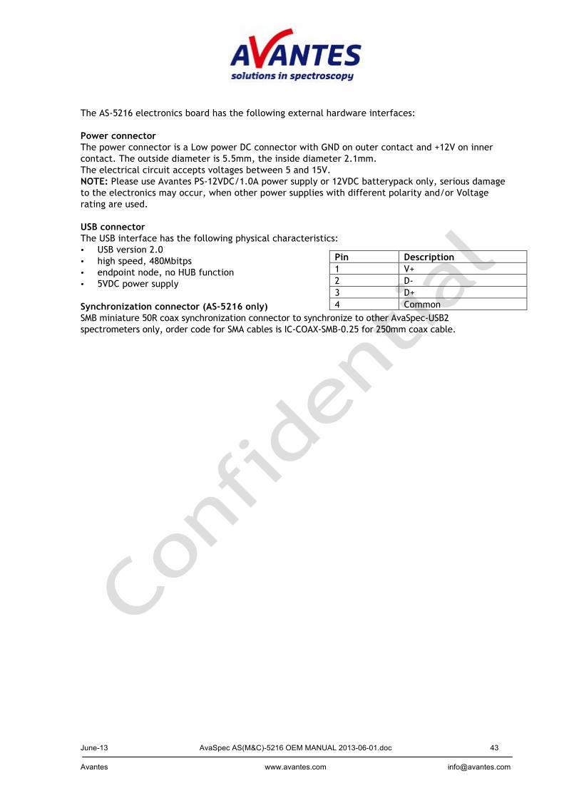
The AS-5216 electronics board has the following external hardware interfaces: Power connector The power connector is a Low power DC connector with GND on outer contact and +12V on inner contact. The outside diameter is 5.5mm, the inside diameter 2.1mm. The electrical circuit accepts voltages between 5 and 15V. NOTE: Please use Avantes PS-12VDC/1.0A power supply or 12VDC batterypack only, serious damage to the electronics may occur, when other power supplies with different polarity and/or Voltage rating are used. USB connector The USB interface has the following physical characteristics: • USB version 2.0 • high speed, 480Mbitps • endpoint node, no HUB function • 5VDC power supply Synchronization connector (AS-5216 only) SMB miniature 50R coax synchronization connector to synchronize to other AvaSpec-USB2 spectrometers only, order code for SMA cables is IC-COAX-SMB-0.25 for 250mm coax cable.
Pin Description 1 V+ 2 D- 3 D+ 4 Common
June-13 AvaSpec AS(M&C)-5216 OEM MANUAL 2013-06-01.doc 44 Avantes www.avantes.com [email protected]
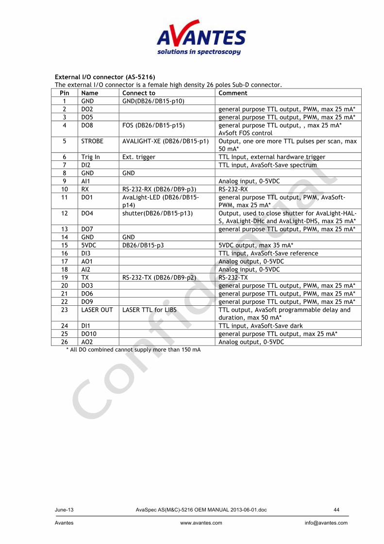
External I/O connector (AS-5216) The external I/O connector is a female high density 26 poles Sub-D connector.
Pin Name Connect to Comment 1 GND GND(DB26/DB15-p10) 2 DO2 general purpose TTL output, PWM, max 25 mA* 3 DO5 general purpose TTL output, PWM, max 25 mA* 4 DO8 FOS (DB26/DB15-p15) general purpose TTL output, , max 25 mA*
AvSoft FOS control 5 STROBE AVALIGHT-XE (DB26/DB15-p1) Output, one ore more TTL pulses per scan, max
50 mA* 6 Trig In Ext. trigger TTL Input, external hardware trigger 7 DI2 TTL input, AvaSoft-Save spectrum 8 GND GND 9 AI1 Analog input, 0-5VDC 10 RX RS-232-RX (DB26/DB9-p3) RS-232-RX 11 DO1 AvaLight-LED (DB26/DB15-
p14) general purpose TTL output, PWM, AvaSoft-PWM, max 25 mA*
12 DO4 shutter(DB26/DB15-p13) Output, used to close shutter for AvaLight-HAL-S, AvaLight-DHc and AvaLight-DHS, max 25 mA*
13 DO7 general purpose TTL output, PWM, max 25 mA* 14 GND GND 15 5VDC DB26/DB15-p3 5VDC output, max 35 mA* 16 DI3 TTL input, AvaSoft-Save reference 17 AO1 Analog output, 0-5VDC 18 AI2 Analog input, 0-5VDC 19 TX RS-232-TX (DB26/DB9-p2) RS-232-TX 20 DO3 general purpose TTL output, PWM, max 25 mA* 21 DO6 general purpose TTL output, PWM, max 25 mA* 22 DO9 general purpose TTL output, PWM, max 25 mA* 23 LASER OUT LASER TTL for LIBS TTL output, AvaSoft programmable delay and
duration, max 50 mA* 24 DI1 TTL input, AvaSoft-Save dark 25 DO10 general purpose TTL output, max 25 mA* 26 AO2 Analog output, 0-5VDC
* All DO combined cannot supply more than 150 mA
June-13 AvaSpec AS(M&C)-5216 OEM MANUAL 2013-06-01.doc 45 Avantes www.avantes.com [email protected]
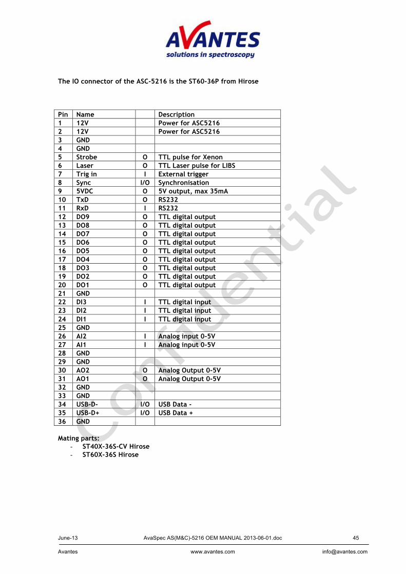
The IO connector of the ASC-5216 is the ST60-36P from Hirose Pin Name Description 1 12V Power for ASC5216 2 12V Power for ASC5216 3 GND 4 GND 5 Strobe O TTL pulse for Xenon 6 Laser O TTL Laser pulse for LIBS 7 Trig in I External trigger 8 Sync I/O Synchronisation 9 5VDC O 5V output, max 35mA 10 TxD O RS232 11 RxD I RS232 12 DO9 O TTL digital output 13 DO8 O TTL digital output 14 DO7 O TTL digital output 15 DO6 O TTL digital output 16 DO5 O TTL digital output 17 DO4 O TTL digital output 18 DO3 O TTL digital output 19 DO2 O TTL digital output 20 DO1 O TTL digital output 21 GND 22 DI3 I TTL digital input 23 DI2 I TTL digital input 24 DI1 I TTL digital input 25 GND 26 AI2 I Analog input 0-5V 27 AI1 I Analog input 0-5V 28 GND 29 GND 30 AO2 O Analog Output 0-5V 31 AO1 O Analog Output 0-5V 32 GND 33 GND 34 USB-D- I/O USB Data - 35 USB-D+ I/O USB Data + 36 GND Mating parts:
- ST40X-36S-CV Hirose - ST60X-36S Hirose
June-13 AvaSpec AS(M&C)-5216 OEM MANUAL 2013-06-01.doc 46 Avantes www.avantes.com [email protected]
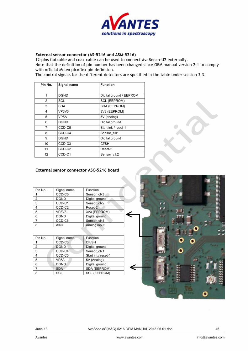
External sensor connector (AS-5216 and ASM-5216) 12-pins flatcable and coax cable can be used to connect AvaBench-U2 externally. Note that the definition of pin number has been changed since OEM manual version 2.1 to comply with official Molex picoflex pin definition. The control signals for the different detectors are specified in the table under section 3.3.
Pin No. Signal name Function
1 DGND Digital ground / EEPROM 2 SCL SCL (EEPROM) 3 SDA SDA (EEPROM) 4 VP3V3 3V3 (EEPROM) 5 VP5A 5V (analog) 6 DGND Digital ground 7 CCD-C5 Start int. / reset-1 8 CCD-C4 Sensor_clk1 9 DGND Digital ground
10 CCD-C3 Cf/SH 11 CCD-C2 Reset-2 12 CCD-C1 Sensor_clk2
External sensor connector ASC-5216 board Pin No. Signal name Function 1 CCD-C0 Sensor_clk3 2 DGND Digital ground 3 CCD-C1 Sensor_clk2 4 CCD-C2 Reset-2 5 VP3V3 3V3 (EEPROM) 6 DGND Digital ground 7 CCD-C6 Sensor_clk4 8 AIN7 Analog input Pin No. Signal name Function 1 CCD-C3 CF/SH 2 DGND Digital ground 3 CCD-C4 Sensor_clk1 4 CCD-C5 Start int./ reset-1 5 VP5A 5V (Analog) 6 DGND Digital ground 7 SDA SDA (EEPROM) 8 SCL SCL (EEPROM)
1
1
June-13 AvaSpec AS(M&C)-5216 OEM MANUAL 2013-06-01.doc 47 Avantes www.avantes.com [email protected]
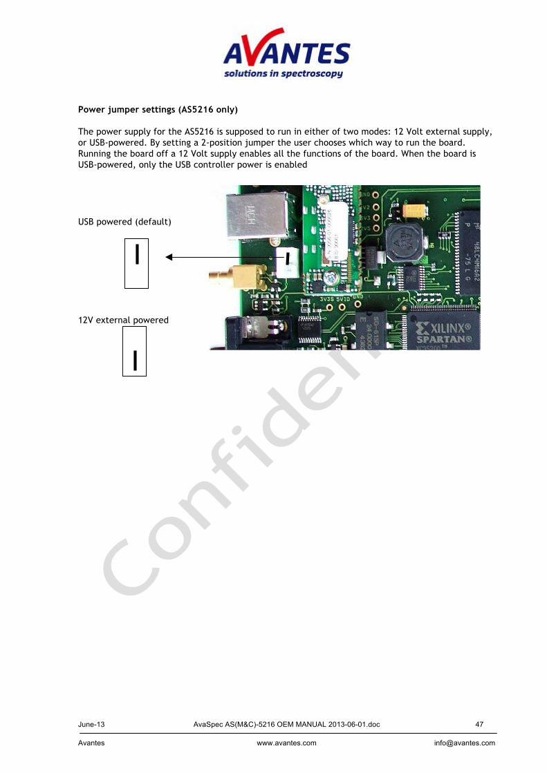
Power jumper settings (AS5216 only) The power supply for the AS5216 is supposed to run in either of two modes: 12 Volt external supply, or USB-powered. By setting a 2-position jumper the user chooses which way to run the board. Running the board off a 12 Volt supply enables all the functions of the board. When the board is USB-powered, only the USB controller power is enabled
USB powered (default)
12V external powered
June-13 AvaSpec AS(M&C)-5216 OEM MANUAL 2013-06-01.doc 48 Avantes www.avantes.com [email protected]
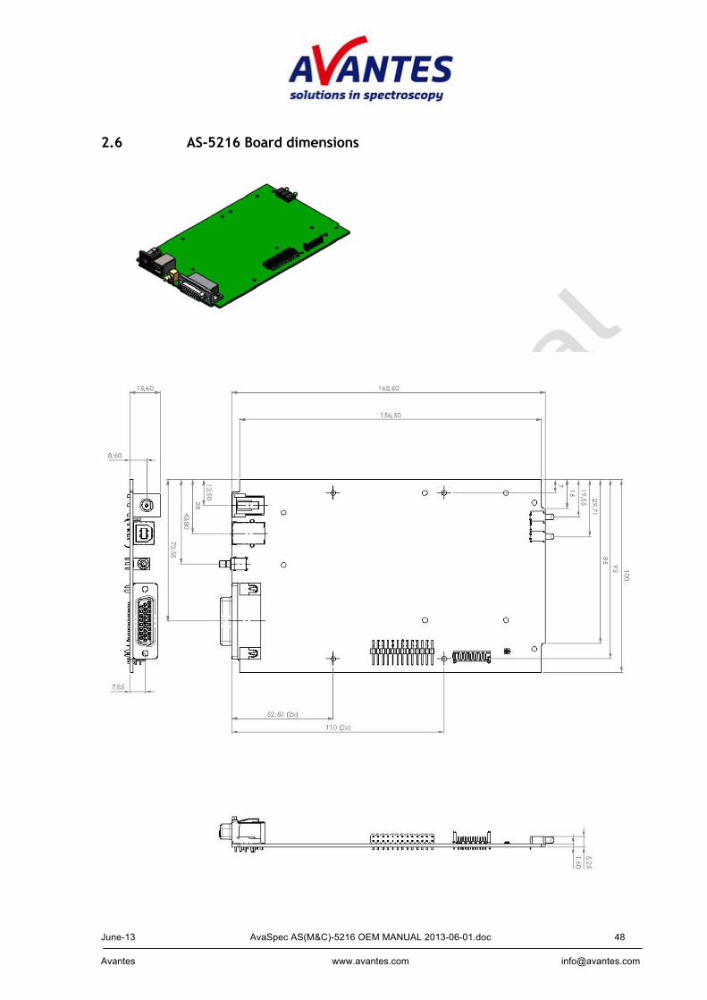
2.6 AS-5216 Board dimensions
June-13 AvaSpec AS(M&C)-5216 OEM MANUAL 2013-06-01.doc 49 Avantes www.avantes.com [email protected]
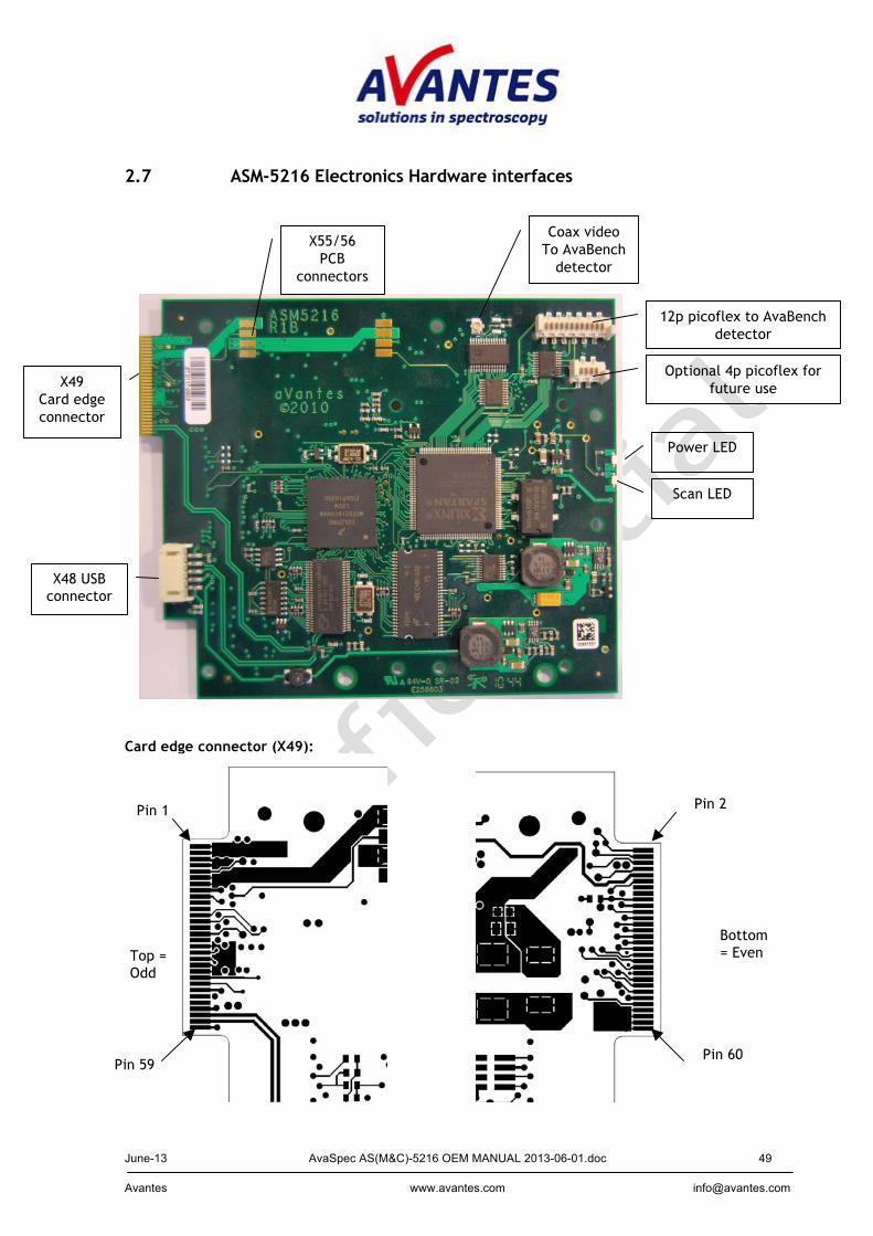
2.7 ASM-5216 Electronics Hardware interfaces
Card edge connector (X49):
12p picoflex to AvaBench detector
X49 Card edge connector
X48 USB connector
X55/56 PCB
connectors
Optional 4p picoflex for future use
Pin 59
Top = Odd
Pin 1
Bottom = Even
Pin 60
Pin 2
Coax video To AvaBench
detector
Power LED
Scan LED
June-13 AvaSpec AS(M&C)-5216 OEM MANUAL 2013-06-01.doc 50 Avantes www.avantes.com [email protected]
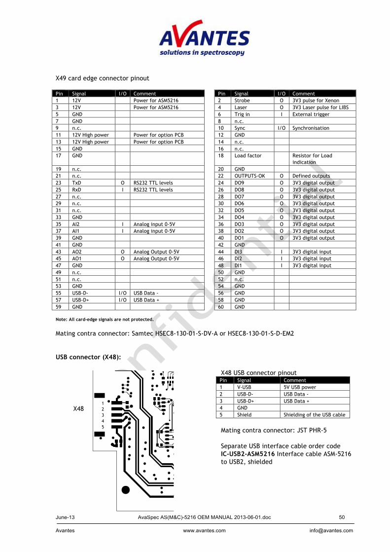
X49 card edge connector pinout Pin Signal I/O Comment Pin Signal I/O Comment 1 12V Power for ASM5216 2 Strobe O 3V3 pulse for Xenon 3 12V Power for ASM5216 4 Laser O 3V3 Laser pulse for LIBS 5 GND 6 Trig in I External trigger 7 GND 8 n.c. 9 n.c. 10 Sync I/O Synchronisation 11 12V High power Power for option PCB 12 GND 13 12V High power Power for option PCB 14 n.c. 15 GND 16 n.c. 17 GND 18 Load factor Resistor for Load
indication 19 n.c. 20 GND 21 n.c. 22 OUTPUTS-OK O Defined outputs 23 TxD O RS232 TTL levels 24 DO9 O 3V3 digital output 25 RxD I RS232 TTL levels 26 DO8 O 3V3 digital output 27 n.c. 28 DO7 O 3V3 digital output 29 n.c. 30 DO6 O 3V3 digital output 31 n.c. 32 DO5 O 3V3 digital output 33 GND 34 DO4 O 3V3 digital output 35 AI2 I Analog input 0-5V 36 DO3 O 3V3 digital output 37 AI1 I Analog input 0-5V 38 DO2 O 3V3 digital output 39 GND 40 DO1 O 3V3 digital output 41 GND 42 GND 43 AO2 O Analog Output 0-5V 44 DI3 I 3V3 digital input 45 AO1 O Analog Output 0-5V 46 DI2 I 3V3 digital input 47 GND 48 DI1 I 3V3 digital input 49 n.c. 50 GND 51 n.c. 52 n.c. 53 GND 54 GND 55 USB-D- I/O USB Data - 56 GND 57 USB-D+ I/O USB Data + 58 GND 59 GND 60 GND Note: All card-edge signals are not protected. Mating contra connector: Samtec HSEC8-130-01-S-DV-A or HSEC8-130-01-S-D-EM2 USB connector (X48): X48 USB connector pinout
Pin Signal Comment 1 V-USB 5V USB power 2 USB-D- USB Data - 3 USB-D+ USB Data + 4 GND 5 Shield Shielding of the USB cable
Mating contra connector: JST PHR-5 Separate USB interface cable order code IC-USB2-ASM5216 Interface cable ASM-5216 to USB2, shielded
1 2 3 4 5
X48
June-13 AvaSpec AS(M&C)-5216 OEM MANUAL 2013-06-01.doc 51 Avantes www.avantes.com [email protected]
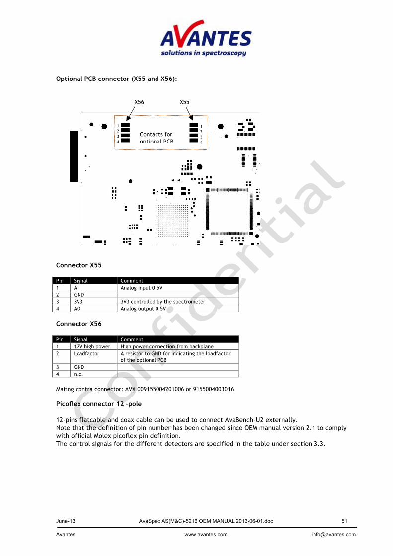
Optional PCB connector (X55 and X56):
Connector X55 Pin Signal Comment 1 AI Analog input 0-5V 2 GND 3 3V3 3V3 controlled by the spectrometer 4 AO Analog output 0-5V
Connector X56 Pin Signal Comment 1 12V high power High power connection from backplane 2 Loadfactor A resistor to GND for indicating the loadfactor
of the optional PCB 3 GND 4 n.c.
Mating contra connector: AVX 009155004201006 or 9155004003016 Picoflex connector 12 –pole 12-pins flatcable and coax cable can be used to connect AvaBench-U2 externally. Note that the definition of pin number has been changed since OEM manual version 2.1 to comply with official Molex picoflex pin definition. The control signals for the different detectors are specified in the table under section 3.3.
Contacts for optional PCB
X56 X55
1 2 3 4
1 2 3 4
June-13 AvaSpec AS(M&C)-5216 OEM MANUAL 2013-06-01.doc 52 Avantes www.avantes.com [email protected]
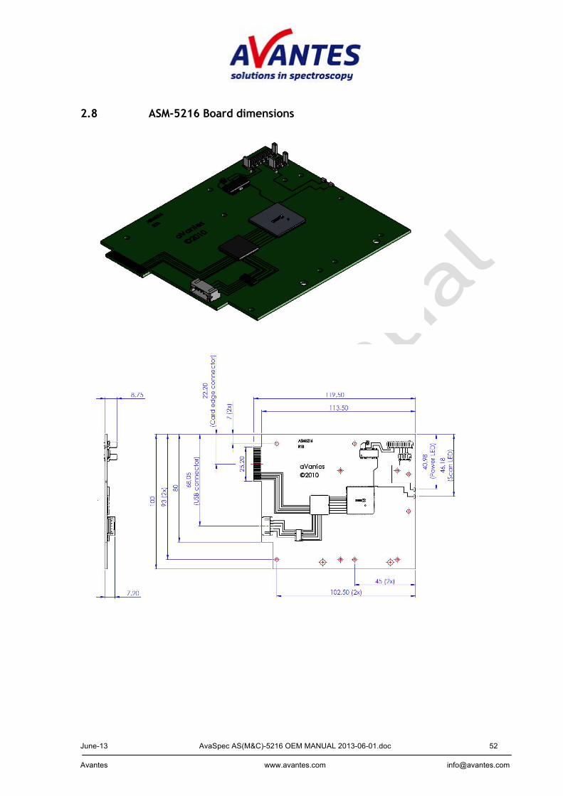
2.8 ASM-5216 Board dimensions
June-13 AvaSpec AS(M&C)-5216 OEM MANUAL 2013-06-01.doc 53 Avantes www.avantes.com [email protected]
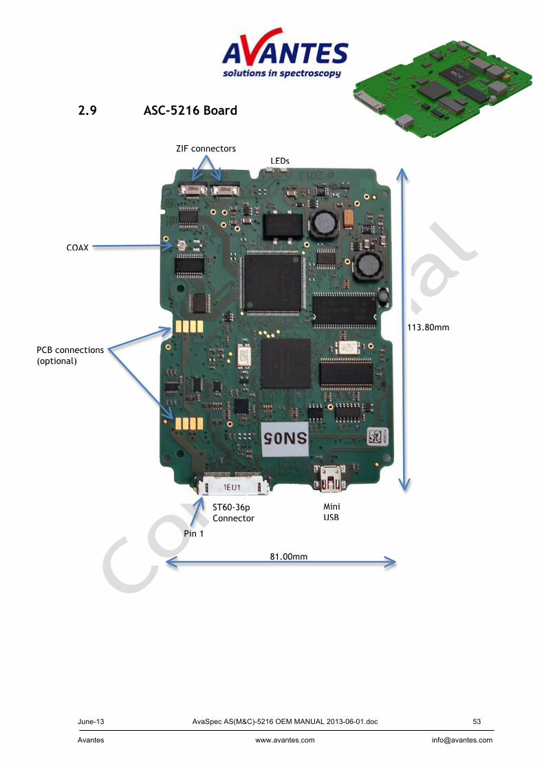
2.9 ASC-5216 Board
PCB connections (optional)
ST60-36p Connector
MiniUSB
LEDs ZIF connectors
COAX
Pin 1
113.80mm
81.00mm

June-13 AvaSpec AS(M&C)-5216 OEM MANUAL 2013-06-01.doc 54 Avantes www.avantes.com [email protected]
3 AvaBench Optical benches AvaBench-75-ULS 3.1 AvaBench UV/VIS Optical Benches Avantes has developed a total of 6 types of optical benches, 4 for the UV/VIS range and 2 for the NIR range, special for OEM customers. The UV/VIS optical benches AvaBench-45, AvaBench-75 and AvaBench-75-ULS are symmetrical Czerny-Turner designs with fiber optic entrance connector (Standard SMA, others possible), collimating and focussing mirror and diffraction grating. A choice of different gratings with different dispersion and blaze angels enable applications in the 200-1100nm range. The newly designed AvaBench-ULS has full mechanical compatibility for mounting holes with the AvaBench-75, so for OEM customers it is easy to upgrade to the better ULS optical bench. The newest design HS bench is a high throughput optical bench with high numerical aperture. Wavelength ranges, resolution tables, detector specifications and AvaBench options can be found in the sections on the AvaSpec products on the website and in the catalog. In the table below the main differences between the optical benches are pointed out. Technical Data AvaBench-45 AvaBench-75 AvaBench-75-ULS AvaBench-
75-ULSI AvaBench-HS
Implemented in AvaSpec-128 / 256
AvaSpec-1024 / 2048(L) / 3648 / 2048x14
AvaSpec-ULS 2048(L) / 3648 / 2048x14 / 2048x16 / 2048x64/ 2048XL
AvaSpec-ULSI 2048(L) / 3648
AvaSpec-HS1024x58TEC /1024x122TEC
Focal length 45 mm 75 mm 37.5 mm Numerical aperture
0.11 0.07 0.22
Wavelength range
200-1100 nm 200-1160 nm
Resolution (FWHM)
1.5 –64 nm 0.05 – 20 nm 1.2 –20 nm
Stray light < 0.3% < 0.1% 0.04-0.1% < 1 % Gratings different Slits 25, 50, 100,
200, 500 µm 10, 25, 50, 100, 250, 500 µm 25, 50, 100,
250, 500 µm Detector TAOS 128 /
HAM 256 HAM 1024 / SONY 2048 / TOSHIBA 3648 /HAM 2048x14
SONY 2048(L) / TOSHIBA 3648 / HAM 2048x14/16/64/XL
SONY 2048(L) / TOSHIBA 3648
HAM 1024x58/122
Detector lens VIS, for TAOS128 only
UV/VIS n.a.
Order sorting filter
See options
Dimensions, weight
82 x 72 x 20 mm, 130 gr.
120 x 91 x 21 mm, 255 gr.
120 x 91 x 21 mm, 350 gr.
120 x 91 x 35 mm, 580 gr
95 x 152 x 42 mm, 722 gr
June-13 AvaSpec AS(M&C)-5216 OEM MANUAL 2013-06-01.doc 55 Avantes www.avantes.com [email protected]
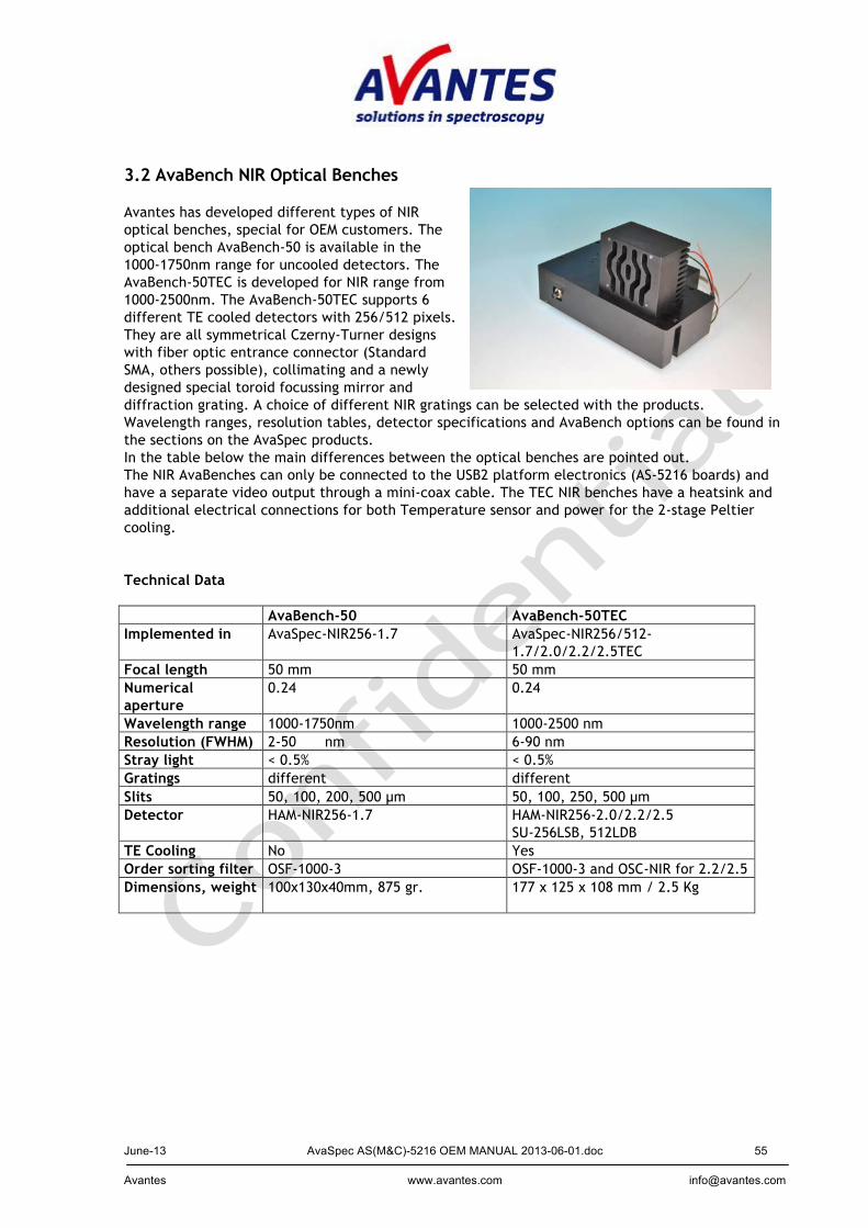
3.2 AvaBench NIR Optical Benches Avantes has developed different types of NIR optical benches, special for OEM customers. The optical bench AvaBench-50 is available in the 1000-1750nm range for uncooled detectors. The AvaBench-50TEC is developed for NIR range from 1000-2500nm. The AvaBench-50TEC supports 6 different TE cooled detectors with 256/512 pixels. They are all symmetrical Czerny-Turner designs with fiber optic entrance connector (Standard SMA, others possible), collimating and a newly designed special toroid focussing mirror and diffraction grating. A choice of different NIR gratings can be selected with the products. Wavelength ranges, resolution tables, detector specifications and AvaBench options can be found in the sections on the AvaSpec products. In the table below the main differences between the optical benches are pointed out. The NIR AvaBenches can only be connected to the USB2 platform electronics (AS-5216 boards) and have a separate video output through a mini-coax cable. The TEC NIR benches have a heatsink and additional electrical connections for both Temperature sensor and power for the 2-stage Peltier cooling.
Technical Data AvaBench-50 AvaBench-50TEC Implemented in AvaSpec-NIR256-1.7 AvaSpec-NIR256/512-
1.7/2.0/2.2/2.5TEC Focal length 50 mm 50 mm Numerical aperture
0.24 0.24
Wavelength range 1000-1750nm 1000-2500 nm Resolution (FWHM) 2-50 nm 6-90 nm Stray light < 0.5% < 0.5% Gratings different different Slits 50, 100, 200, 500 µm 50, 100, 250, 500 µm Detector HAM-NIR256-1.7 HAM-NIR256-2.0/2.2/2.5
SU-256LSB, 512LDB TE Cooling No Yes Order sorting filter OSF-1000-3 OSF-1000-3 and OSC-NIR for 2.2/2.5 Dimensions, weight 100x130x40mm, 875 gr.
177 x 125 x 108 mm / 2.5 Kg
June-13 AvaSpec AS(M&C)-5216 OEM MANUAL 2013-06-01.doc 56 Avantes www.avantes.com [email protected]
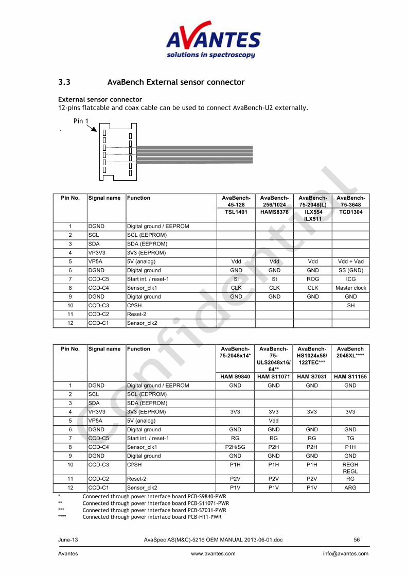
3.3 AvaBench External sensor connector External sensor connector 12-pins flatcable and coax cable can be used to connect AvaBench-U2 externally. Pin No. Signal name Function AvaBench-
45-128 AvaBench-256/1024
AvaBench-75-2048(L)
AvaBench-75-3648
TSL1401 HAMS8378 ILX554 ILX511
TCD1304
1 DGND Digital ground / EEPROM 2 SCL SCL (EEPROM) 3 SDA SDA (EEPROM) 4 VP3V3 3V3 (EEPROM) 5 VP5A 5V (analog) Vdd Vdd Vdd Vdd + Vad 6 DGND Digital ground GND GND GND SS (GND) 7 CCD-C5 Start int. / reset-1 Si St ROG ICG 8 CCD-C4 Sensor_clk1 CLK CLK CLK Master clock 9 DGND Digital ground GND GND GND GND
10 CCD-C3 Cf/SH SH 11 CCD-C2 Reset-2
12 CCD-C1 Sensor_clk2
Pin No. Signal name Function AvaBench-
75-2048x14* AvaBench-
75-ULS2048x16/
64**
AvaBench-HS1024x58/ 122TEC***
AvaBench 2048XL****
HAM S9840 HAM S11071 HAM S7031 HAM S11155 1 DGND Digital ground / EEPROM GND GND GND GND 2 SCL SCL (EEPROM) 3 SDA SDA (EEPROM) 4 VP3V3 3V3 (EEPROM) 3V3 3V3 3V3 3V3 5 VP5A 5V (analog) Vdd 6 DGND Digital ground GND GND GND GND 7 CCD-C5 Start int. / reset-1 RG RG RG TG 8 CCD-C4 Sensor_clk1 P2H/SG P2H P2H P1H 9 DGND Digital ground GND GND GND GND
10 CCD-C3 Cf/SH P1H P1H P1H REGH REGL
11 CCD-C2 Reset-2 P2V P2V P2V RG 12 CCD-C1 Sensor_clk2 P1V P1V P1V ARG
* Connected through power interface board PCB-S9840-PWR ** Connected through power interface board PCB-S11071-PWR *** Connected through power interface board PCB-S7031-PWR **** Connected through power interface board PCB-H11-PWR
Pin 1
June-13 AvaSpec AS(M&C)-5216 OEM MANUAL 2013-06-01.doc 57 Avantes www.avantes.com [email protected]
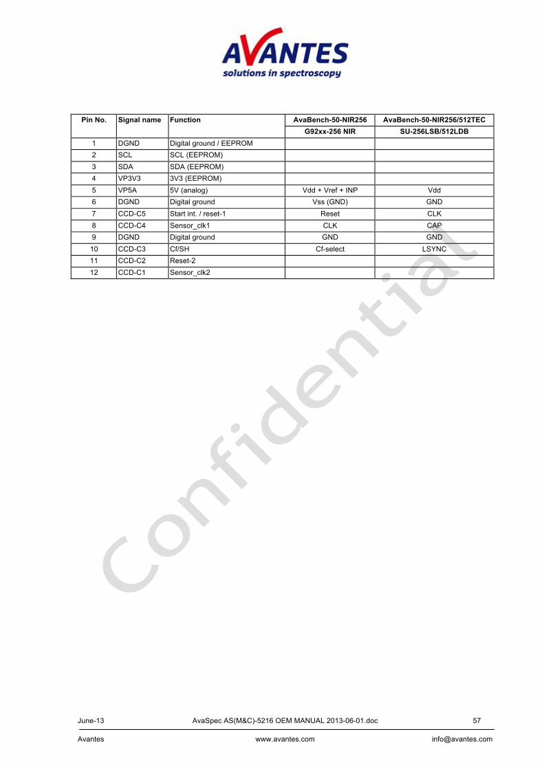
Pin No. Signal name Function AvaBench-50-NIR256 AvaBench-50-NIR256/512TEC
G92xx-256 NIR SU-256LSB/512LDB 1 DGND Digital ground / EEPROM 2 SCL SCL (EEPROM) 3 SDA SDA (EEPROM) 4 VP3V3 3V3 (EEPROM) 5 VP5A 5V (analog) Vdd + Vref + INP Vdd 6 DGND Digital ground Vss (GND) GND 7 CCD-C5 Start int. / reset-1 Reset CLK 8 CCD-C4 Sensor_clk1 CLK CAP 9 DGND Digital ground GND GND
10 CCD-C3 Cf/SH Cf-select LSYNC 11 CCD-C2 Reset-2
12 CCD-C1 Sensor_clk2
June-13 AvaSpec AS(M&C)-5216 OEM MANUAL 2013-06-01.doc 58 Avantes www.avantes.com [email protected]
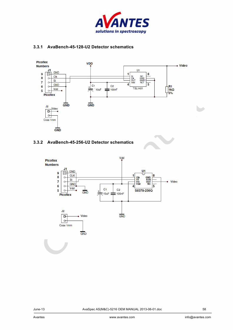
3.3.1 AvaBench-45-128-U2 Detector schematics
3.3.2 AvaBench-45-256-U2 Detector schematics
June-13 AvaSpec AS(M&C)-5216 OEM MANUAL 2013-06-01.doc 59 Avantes www.avantes.com [email protected]
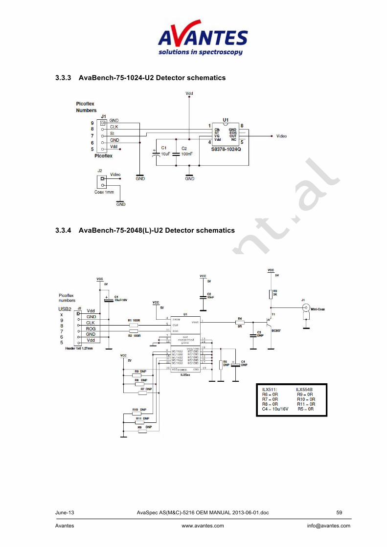
3.3.3 AvaBench-75-1024-U2 Detector schematics
3.3.4 AvaBench-75-2048(L)-U2 Detector schematics

June-13 AvaSpec AS(M&C)-5216 OEM MANUAL 2013-06-01.doc 60 Avantes www.avantes.com [email protected]
3.3.5 AvaBench-75-3648–U2 Detector schematics
3.3.6 AvaBench-75-2048x14–U2 Detector schematics PCB-S9840-PWR power print (separate)
Detector print
June-13 AvaSpec AS(M&C)-5216 OEM MANUAL 2013-06-01.doc 61 Avantes www.avantes.com [email protected]
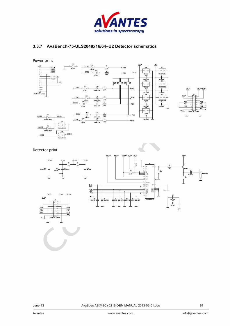
3.3.7 AvaBench-75-ULS2048x16/64–U2 Detector schematics Power print
Detector print
June-13 AvaSpec AS(M&C)-5216 OEM MANUAL 2013-06-01.doc 62 Avantes www.avantes.com [email protected]
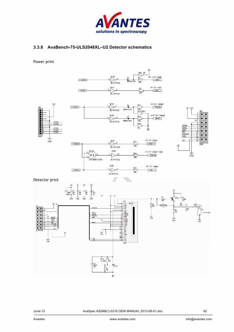
3.3.8 AvaBench-75-ULS2048XL–U2 Detector schematics Power print
Detector print
June-13 AvaSpec AS(M&C)-5216 OEM MANUAL 2013-06-01.doc 63 Avantes www.avantes.com [email protected]
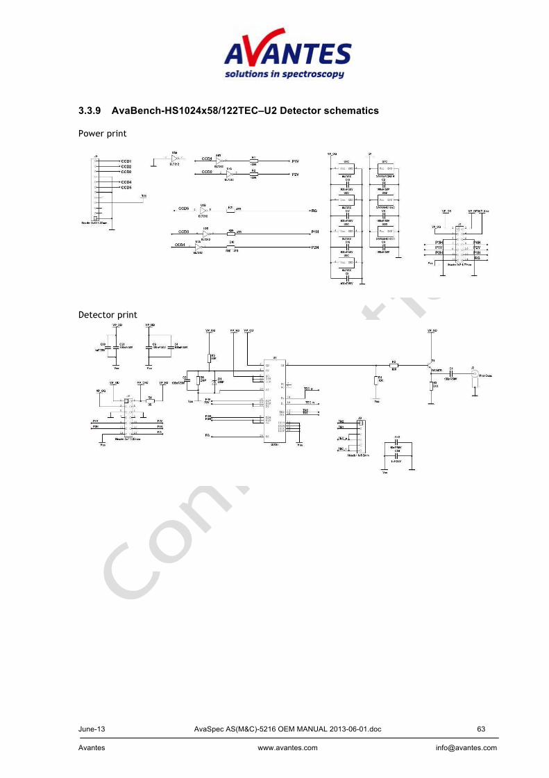
3.3.9 AvaBench-HS1024x58/122TEC–U2 Detector schematics Power print
Detector print
June-13 AvaSpec AS(M&C)-5216 OEM MANUAL 2013-06-01.doc 64 Avantes www.avantes.com [email protected]
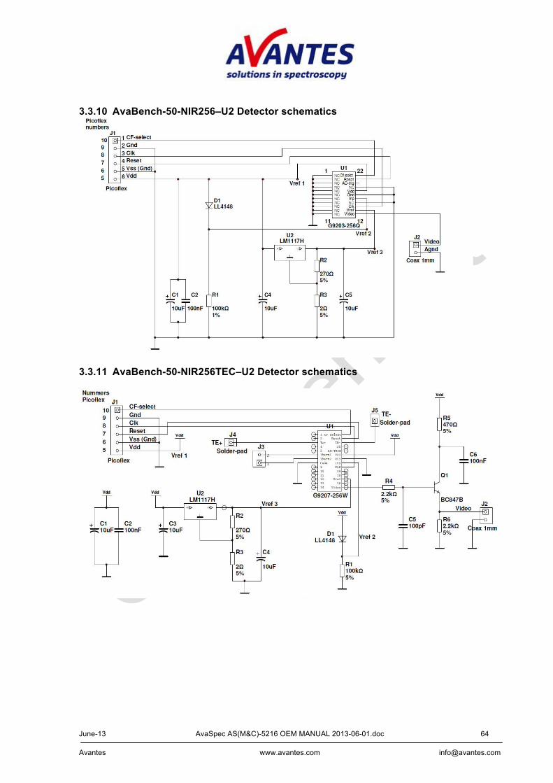
3.3.10 AvaBench-50-NIR256–U2 Detector schematics
3.3.11 AvaBench-50-NIR256TEC–U2 Detector schematics
June-13 AvaSpec AS(M&C)-5216 OEM MANUAL 2013-06-01.doc 65 Avantes www.avantes.com [email protected]
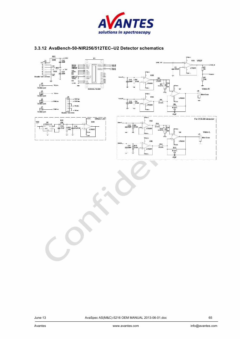
3.3.12 AvaBench-50-NIR256/512TEC–U2 Detector schematics
June-13 AvaSpec AS(M&C)-5216 OEM MANUAL 2013-06-01.doc 66 Avantes www.avantes.com [email protected]
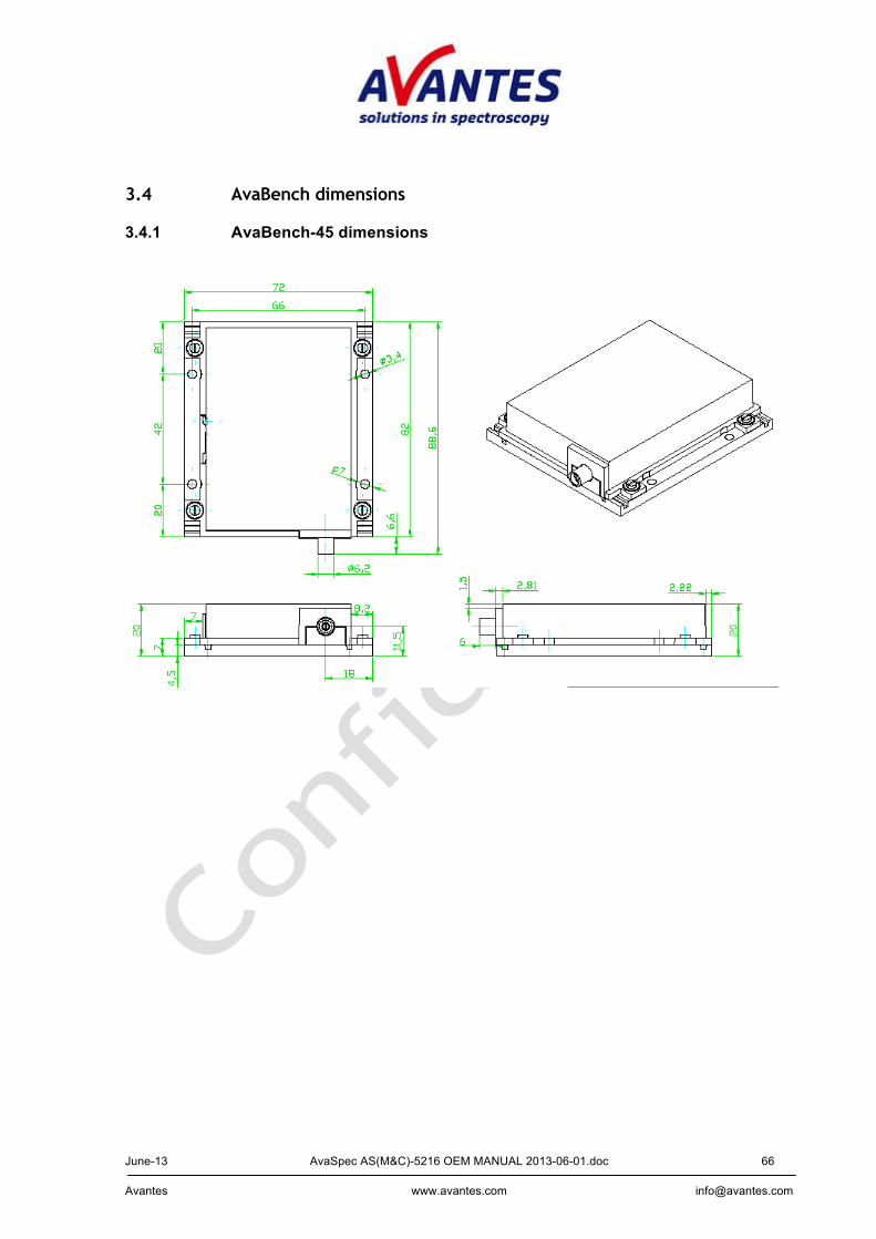
3.4 AvaBench dimensions 3.4.1 AvaBench-45 dimensions

June-13 AvaSpec AS(M&C)-5216 OEM MANUAL 2013-06-01.doc 67 Avantes www.avantes.com [email protected]
3.4.2 AvaBench-75 dimensions
June-13 AvaSpec AS(M&C)-5216 OEM MANUAL 2013-06-01.doc 68 Avantes www.avantes.com [email protected]
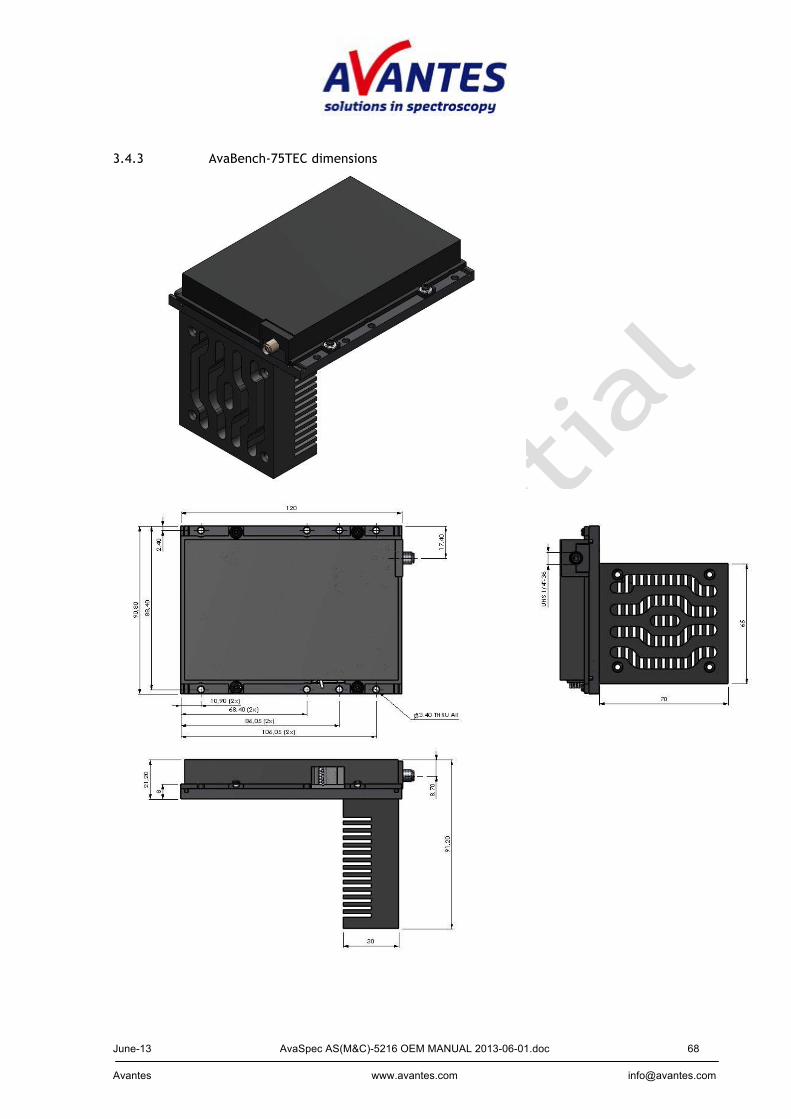
3.4.3 AvaBench-75TEC dimensions
June-13 AvaSpec AS(M&C)-5216 OEM MANUAL 2013-06-01.doc 69 Avantes www.avantes.com [email protected]
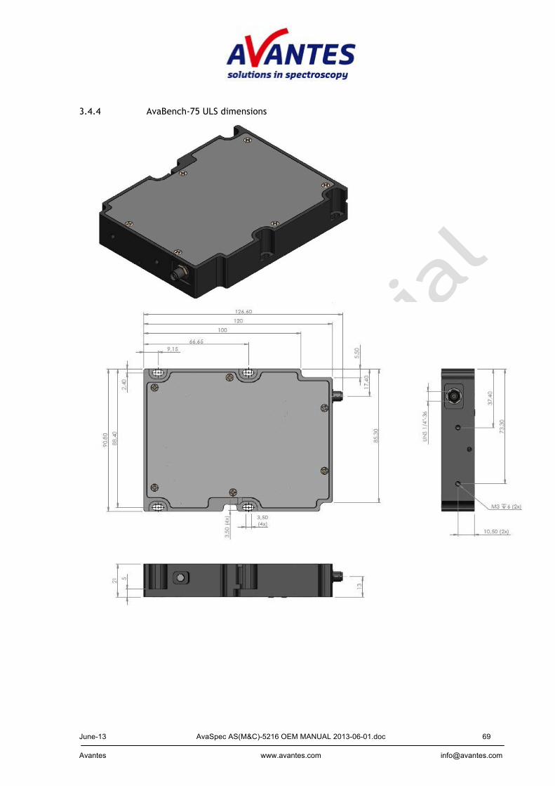
3.4.4 AvaBench-75 ULS dimensions
June-13 AvaSpec AS(M&C)-5216 OEM MANUAL 2013-06-01.doc 70 Avantes www.avantes.com [email protected]
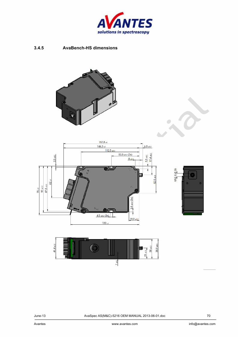
3.4.5 AvaBench-HS dimensions
June-13 AvaSpec AS(M&C)-5216 OEM MANUAL 2013-06-01.doc 71 Avantes www.avantes.com [email protected]
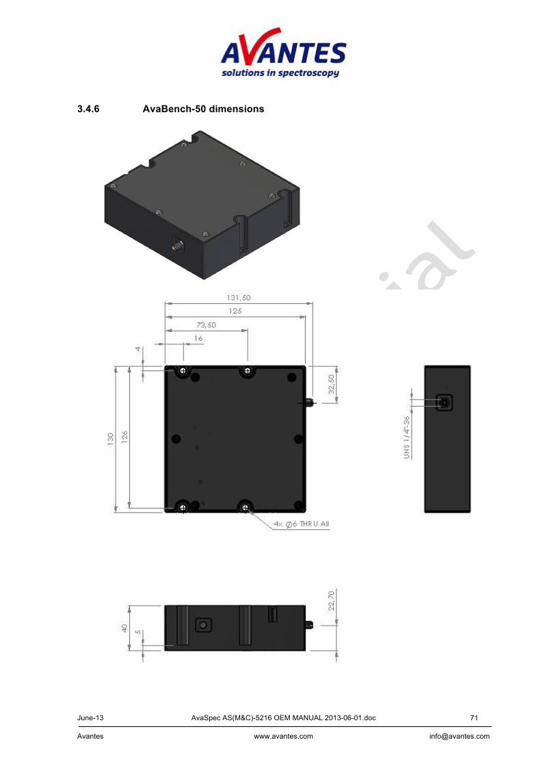
3.4.6 AvaBench-50 dimensions
June-13 AvaSpec AS(M&C)-5216 OEM MANUAL 2013-06-01.doc 72 Avantes www.avantes.com [email protected]
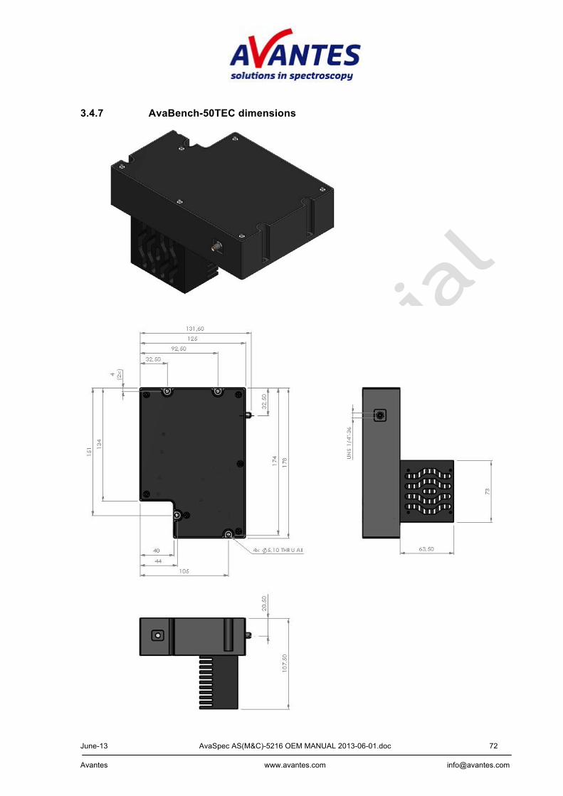
3.4.7 AvaBench-50TEC dimensions
June-13 AvaSpec AS(M&C)-5216 OEM MANUAL 2013-06-01.doc 73 Avantes www.avantes.com [email protected]
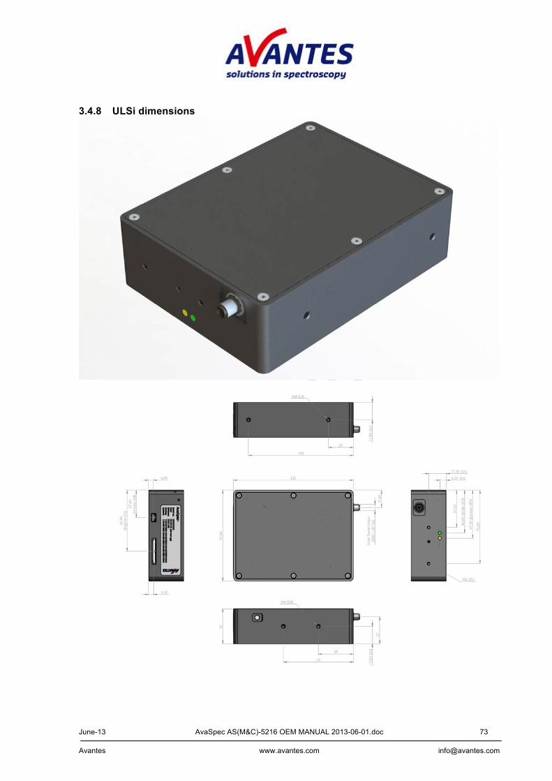
3.4.8 ULSi dimensions
June-13 AvaSpec AS(M&C)-5216 OEM MANUAL 2013-06-01.doc 74 Avantes www.avantes.com [email protected]
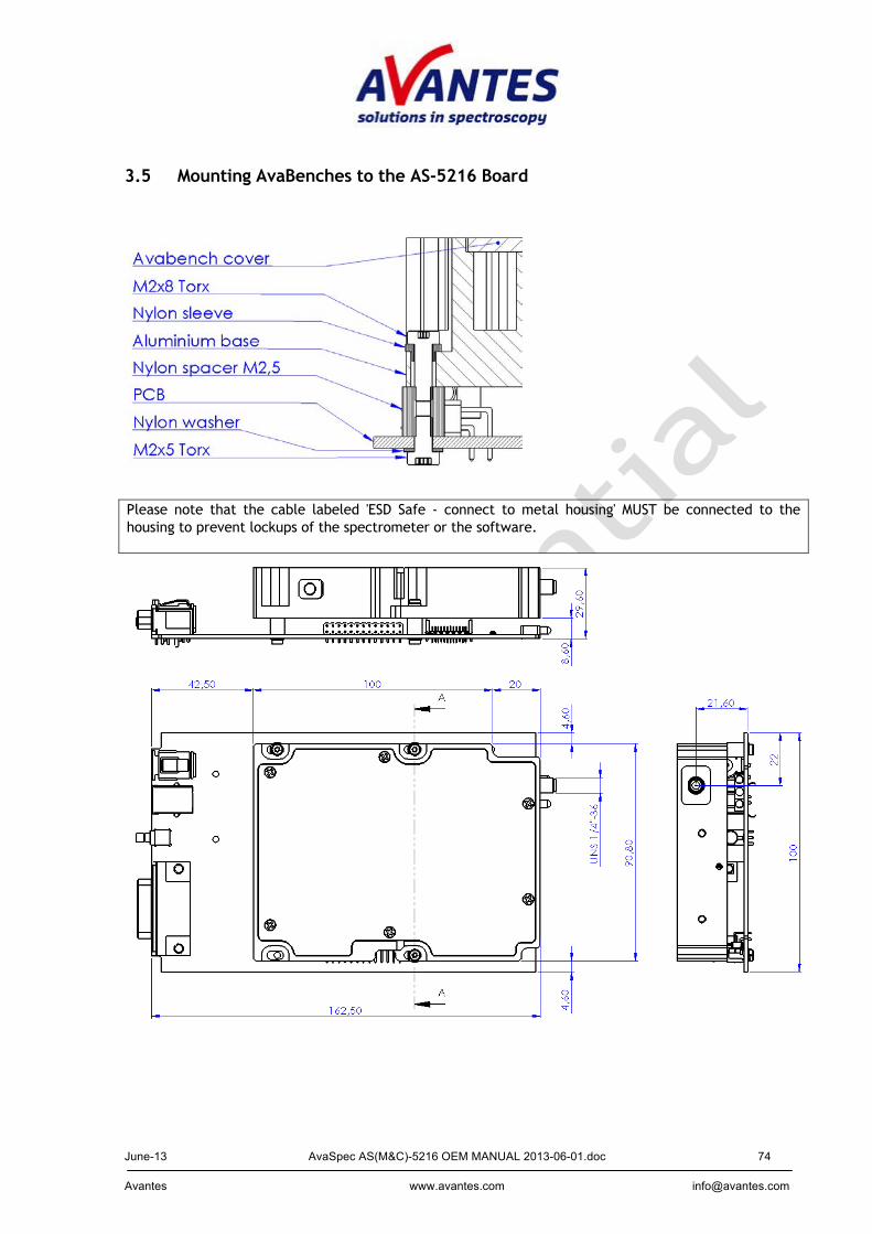
3.5 Mounting AvaBenches to the AS-5216 Board
Please note that the cable labeled 'ESD Safe - connect to metal housing' MUST be connected to the housing to prevent lockups of the spectrometer or the software.
June-13 AvaSpec AS(M&C)-5216 OEM MANUAL 2013-06-01.doc 75 Avantes www.avantes.com [email protected]
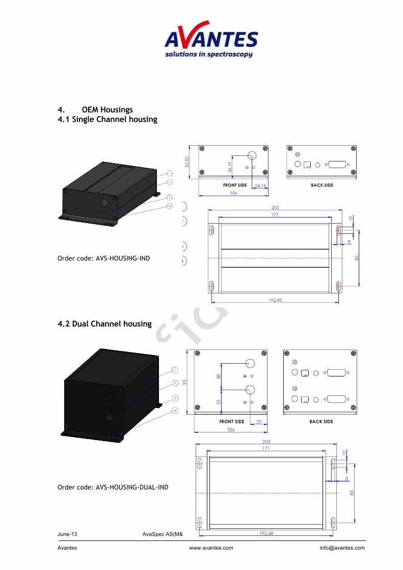
4. OEM Housings 4.1 Single Channel housing Order code: AVS-HOUSING-IND 4.2 Dual Channel housing Order code: AVS-HOUSING-DUAL-IND