Avanti hydraulic socket wrench - HYTORC Benelux
59
Avanti hydraulic socket wrench Technical manual
Transcript of Avanti hydraulic socket wrench - HYTORC Benelux
Avanti hydraulic socket wrench
Technical manual
2
Copyright© 2016 HYTORC. All rights reserved.This document or parts thereof may not be reproduced, copied, distributed, stored in a retrieval system, or transmitted, in any form or by any means, electronically nor otherwise, without the prior written consent of HYTORC.Specifications and illustrations are subject to change without prior notice. HYTORC will not accept liability for any alter-ation or typing error. Details and values given in this manual are average values and have been compiled with care. De-tails and values are not binding. HYTORC disclaims any liability for damage or detriments suffered as a result of reliance on the information given herein or the use of products, processes or equipment to which this document refers.
3
Content1. About the document ............................................................................................... 7
1.1 Purpose of the document ........................................................................................................................ 71.2 How to work with the document ............................................................................................................. 71.3 Languages .............................................................................................................................................. 71.4 Illustrations ............................................................................................................................................. 71.5 Safety symbols in the document ............................................................................................................. 71.6 Related documents ................................................................................................................................. 81.7 Revision history ...................................................................................................................................... 81.8 Contact information ............................................................................................................................... 8
2. Safety ..................................................................................................................... 92.1 General safety instructions .................................................................................................................... 9
2.1.1 Personnel ................................................................................................................................................... 92.1.2 Work area ................................................................................................................................................. 92.1.3 Equipment ................................................................................................................................................. 9
2.2 Additional safety instructions ............................................................................................................... 102.2.1 Electric and pneumatic pump units ....................................................................................................... 102.2.2 Electric pump units ................................................................................................................................. 102.2.3 Hydraulic hoses ...................................................................................................................................... 102.2.4 Reaction arms ......................................................................................................................................... 102.2.5 Sockets .....................................................................................................................................................11
2.3 Safety symbols on the tool ................................................................................................................... 112.4 Qualified personnel ............................................................................................................................. 122.5 Liability ................................................................................................................................................ 12
3. Description ............................................................................................................ 133.1 3Intended use ...................................................................................................................................... 133.2 Overview ............................................................................................................................................. 133.3 Electric pump unit ................................................................................................................................. 14
3.3.1 LED indicators (electric pump unit ........................................................................................................ 143.4 Pneumatic pump unit ............................................................................................................................ 153.5 Hydraulic socket wrench ...................................................................................................................... 163.6 Accessories .......................................................................................................................................... 17
3.6.1 Safety handle ......................................................................................................................................... 173.6.2 BoltSafe load tester ................................................................................................................................ 173.6.3 Torque and angle sensor ....................................................................................................................... 17
4. Installation ............................................................................................................ 194.1 Hydraulic hoses .................................................................................................................................... 19
4.1.1 Hydraulic hose connections .................................................................................................................. 194.1.2 Connecting the hydraulic hoses ............................................................................................................ 214.1.3 Disconnecting the hydraulic hoses ....................................................................................................... 21
4.2 Power supply (electric pump units) .......................................................................................................224.2.1 Connecting the power supply (230V) .................................................................................................224.2.2 Connecting the power supply (400V) .................................................................................................22
4.3 Air supply (pneumatic pump units)....................................................................................................... 234.4 Explosion protection (pneumatic pump units) ...................................................................................... 23
4
5. Reaction arms ....................................................................................................... 255.1 Standard reaction arm (360°) .............................................................................................................255.2 Standard reaction arm (360° x 360°) ................................................................................................255.3 Straight TPF reaction arm ..................................................................................................................... 265.4 Straight WTCT reaction arm with reaction cup .................................................................................... 265.5 Curved WTCT reaction arm with reaction pin cup ............................................................................... 275.6 Curved reaction arm with dual-end reaction cup ................................................................................275.7 Reaction arm for recessed installation ................................................................................................. 28
5.7.1 Fixed length ............................................................................................................................................ 285.7.2 Adjustable length ................................................................................................................................... 28
5.8 Straight dual-tool interconnect reaction arm ....................................................................................... 295.9 U-shaped dual-tool interconnect reaction arm .................................................................................... 295.10 Multi-tool interconnect reaction arm ...................................................................................................305.11 Reaction ring ........................................................................................................................................305.12 Reaction strip (recessed bolt heads) .................................................................................................... 315.13 HYTORC Washer™ double-drive socket .............................................................................................. 315.14 HYTORC LoadDISC™ double-drive socket ......................................................................................... 325.15 HYTORC Nut™ drive ............................................................................................................................ 325.16 Offset-link ............................................................................................................................................33
6. Securing the sockets and reaction arms ............................................................... 356.1 Securing the socket (type 1 .................................................................................................................. 356.2 Securing the sockets (type 2) ............................................................................................................... 356.3 Securing the reaction arm onto the spline shaft ................................................................................... 36
7. Operation ............................................................................................................. 377.1 Inspections before use ......................................................................................................................... 377.2 Remote control ..................................................................................................................................... 37
7.2.1 Electric pump unitt .................................................................................................................................. 377.2.2 Pneumatic pump unitt .............................................................................................................................38
7.3 Disengagement lever for reaction pawl ............................................................................................... 387.4 Torque .................................................................................................................................................. 39
7.4.1 Pressure/torque chart ............................................................................................................................397.4.2 Setting the torque ...................................................................................................................................40
7.5 Direction of rotation ............................................................................................................................. 417.5.1 Determining the direction of rotation ................................................................................................... 417.5.2 Changing the direction of rotation ....................................................................................................... 41
7.6 Tightening and loosening a bolted flange connection ......................................................................... 427.6.1 Tightening a bolted flange connection ................................................................................................427.6.2 Loosening a bolted flange connectionn ..............................................................................................43
7.7 Automatic shut-off system ....................................................................................................................437.8 Thermal protection ...............................................................................................................................43
8. Maintenance & Storage .......................................................................................458.1 Preventive maintenance .......................................................................................................................458.2 Maintenance by HYTORC ....................................................................................................................458.3 Storing the cables ................................................................................................................................45
9. Troubleshooting .................................................................................................... 479.1 Tools ..................................................................................................................................................... 479.2 Pump units ............................................................................................................................................48
9.2.1 General ...................................................................................................................................................489.2.2 Electric pump units .................................................................................................................................499.2.3 Pneumatic pump units ............................................................................................................................49
5
10. Technical data ....................................................................................................... 5110.1 Avanti p7.............................................................................................................................................. 5110.2 Avanti 1 ................................................................................................................................................ 5110.3 Avanti 3 ................................................................................................................................................ 5210.4 Avanti 5 ................................................................................................................................................ 5210.5 Avanti 8 ................................................................................................................................................ 5210.6 Avanti 10 .............................................................................................................................................5310.7 Avanti 20 .............................................................................................................................................5310.8 Avanti 35 .............................................................................................................................................5310.9 Avanti 50 .............................................................................................................................................5410.10 Avanti 80 .............................................................................................................................................5410.11 Avanti 130 ...........................................................................................................................................5410.12 Swivel rotation .....................................................................................................................................5510.13 Physical conditions ...............................................................................................................................5510.14 Maximum torque values (hex drives and male hex sockets .................................................................56
11. Conformiteitsverklaring ....................................................................................... 59

6
About the document
7
1. About the document
1.1 Purpose of the document
The document shows the information to do these steps:• Install the equipment• Operate the equipment• Maintain the equipment
The document contains the original instructions for the Avanti hydraulic socket wrench, to which is referred with the term ‘tool’. The term ‘equipment’ is used as a more general term to refer to the entire system: the tool, its parts and its accessories, including the pump unit.
1.2 How to work with the document
1. Read the document completely. Make sure that you understand all the instructions.2. Obey the safety instructions to prevent injury or damage to equipment.3. Do the procedures completely and in the given sequence.4. Keep a copy of the latest version of the document and all related documents near the equipment.
1.3 Languages
The original language of the document is English. All other language versions are translations of the original instructions.
1.4 Illustrations
It is not always possible to provide a detailed illustration of every single item of the equipment. The illustrations in the document show a typical setup and are for instructional use only.
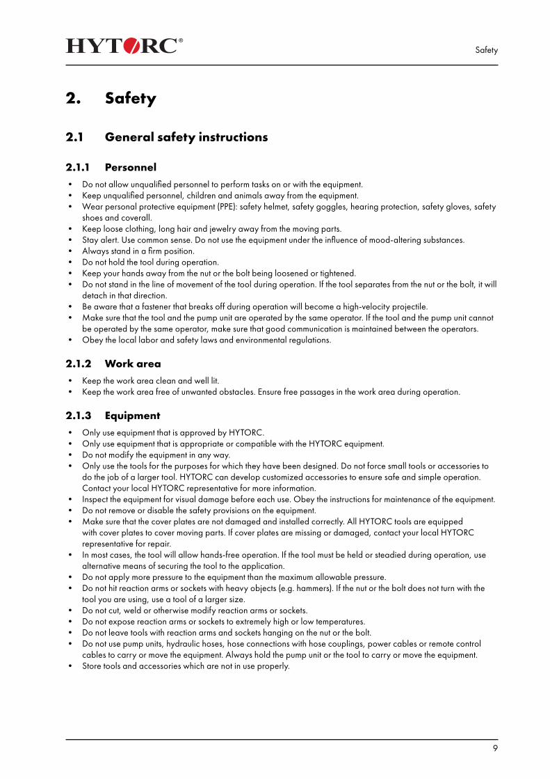
1.5 Safety symbols in the document
Safety symbol Function Description
Warning “Warning” means that injury or death is possible if you do not obey the instructions.
Caution “Caution” means that damage to equipment is possible if you do not obey the instructions.
Note “Note” is used to give additional information.
About the document
8
1.6 Related documents
Document name Target group
Avanti hydraulic socket wrench User manual Personnel who operates the equipment
1.7 Revision history
Date Revision number Comment
18-07-2016 001 First version
1.8 Contact information
HYTORC Nederland BV HYTORC Benelux BVBA
Platinawerf 86641 TL BeuningenNederlandTelefoon: +31 (0)24 3660660Website: www.hytorc.nl E-mail: [email protected]
Ysselaarlaan 65B2630 AartselaarBelgiëTelefoon: +32 (0)38 705220 Website: www.hytorc.beE-mail: [email protected]
Safety
9
2. Safety
2.1 General safety instructions
2.1.1 Personnel• Do not allow unqualified personnel to perform tasks on or with the equipment.• Keep unqualified personnel, children and animals away from the equipment.• Wear personal protective equipment (PPE): safety helmet, safety goggles, hearing protection, safety gloves, safety
shoes and coverall.• Keep loose clothing, long hair and jewelry away from the moving parts.• Stay alert. Use common sense. Do not use the equipment under the influence of mood-altering substances.• Always stand in a firm position.• Do not hold the tool during operation.• Keep your hands away from the nut or the bolt being loosened or tightened.• Do not stand in the line of movement of the tool during operation. If the tool separates from the nut or the bolt, it will
detach in that direction.• Be aware that a fastener that breaks off during operation will become a high-velocity projectile.• Make sure that the tool and the pump unit are operated by the same operator. If the tool and the pump unit cannot
be operated by the same operator, make sure that good communication is maintained between the operators.• Obey the local labor and safety laws and environmental regulations.
2.1.2 Work area• Keep the work area clean and well lit.• Keep the work area free of unwanted obstacles. Ensure free passages in the work area during operation.
2.1.3 Equipment• Only use equipment that is approved by HYTORC.• Only use equipment that is appropriate or compatible with the HYTORC equipment.• Do not modify the equipment in any way.• Only use the tools for the purposes for which they have been designed. Do not force small tools or accessories to
do the job of a larger tool. HYTORC can develop customized accessories to ensure safe and simple operation. Contact your local HYTORC representative for more information.
• Inspect the equipment for visual damage before each use. Obey the instructions for maintenance of the equipment.• Do not remove or disable the safety provisions on the equipment.• Make sure that the cover plates are not damaged and installed correctly. All HYTORC tools are equipped
with cover plates to cover moving parts. If cover plates are missing or damaged, contact your local HYTORC representative for repair.
• In most cases, the tool will allow hands-free operation. If the tool must be held or steadied during operation, use alternative means of securing the tool to the application.
• Do not apply more pressure to the equipment than the maximum allowable pressure.• Do not hit reaction arms or sockets with heavy objects (e.g. hammers). If the nut or the bolt does not turn with the
tool you are using, use a tool of a larger size.• Do not cut, weld or otherwise modify reaction arms or sockets.• Do not expose reaction arms or sockets to extremely high or low temperatures.• Do not leave tools with reaction arms and sockets hanging on the nut or the bolt.• Do not use pump units, hydraulic hoses, hose connections with hose couplings, power cables or remote control
cables to carry or move the equipment. Always hold the pump unit or the tool to carry or move the equipment.• Store tools and accessories which are not in use properly.
Safety
10
2.2 Additional safety instructions
2.2.1 Electric and pneumatic pump units• Only use HYTORC pump units.• Do not modify the pump unit in any way.• Do not use the electric pump unit in atmospheres which are potentially volatile. If there is doubt, use a pneumatic
pump unit. Metal-to-metal contact can cause sparks. Take appropriate additional measures.• Wear hearing protection. The sound emission of HYTORC pump units is less than 80 dB.• Make sure that the maximum operating pressure of the pump unit is not higher than the maximum permitted
pressure of 700 bar (10,000 psi).• Make sure that the pump unit is properly grounded.• Make sure that the pump unit is filled with the (supplied) hydraulic oil (Shell Tellus S2 V32).• Make sure that the oil level in the oil tank is beween the minimum mark and the maximum mark. Use the oil level
sight glasses to check the oil level.• To refill the oil tank with hydraulic oil, use only high-grade hydraulic oil (ISO VG 32 or ISO VG 46 in more extreme
conditions).• Do not mix different grades of hydraulic oil.• Make sure that the oil filler cap is placed on the oil filling point.
2.2.2 Electric pump units• Make sure that the mains voltage corresponds to the rated voltage of the pump unit.• For 230V pump units, the mains voltage must be between 200V and 230V.• For 400V pump units, the mains voltage must be between 380V and 460V.• If you use an extension cable:• Do not use an extension cable longer than necessary.• Make sure that the length of the extension cable does not exceed 50 metres.• Make sure that the cross section of the wires in the extension cable is at least 2.5 mm2.• Fully unroll the extension cable from the cable drum.• Make sure that there is no overvoltage or undervoltage. Do not use extension cables that are too thin or too long.• If you use a 400V pump unit, make sure that the direction of rotation is correct. When the LED indicator becomes
red, the direction of rotation is incorrect. Reverse the polarity of the phase inverter plug.
2.2.3 Hydraulic hoses• Only use HYTORC hydraulic hoses.• Do not modify the hydraulic hoses in any way.• Make sure that the hydraulic hoses are securely connected.• Make sure that the hydraulic hoses are not kinked or twisted.• Keep the hydraulic hoses away from the reaction point.• Replace damaged hydraulic hoses immediately. Replace the hydraulic hoses at least every three years.
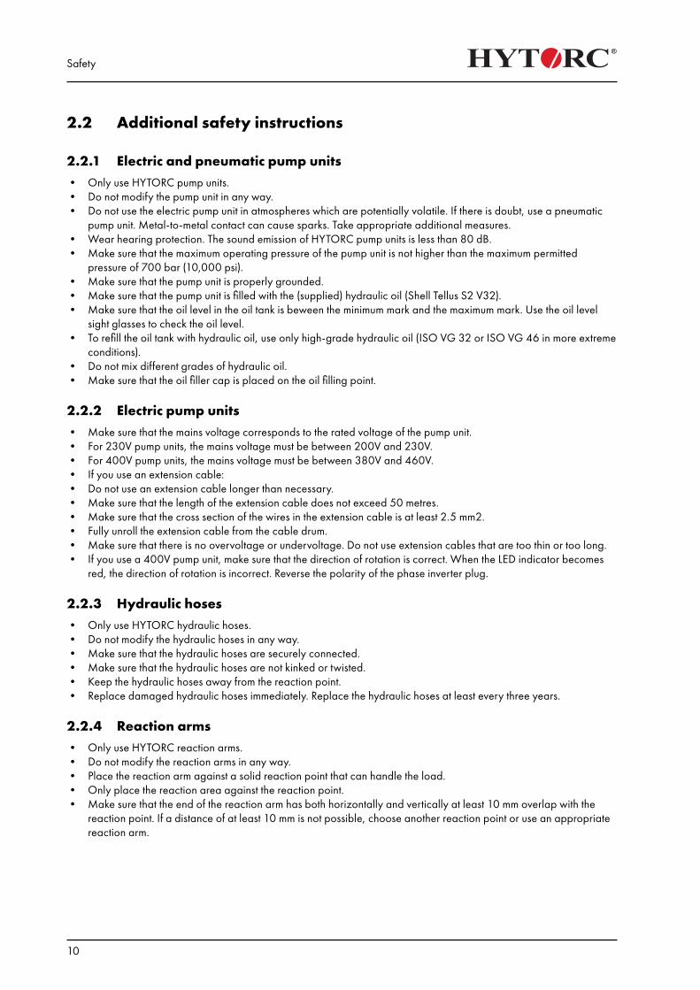
2.2.4 Reaction arms• Only use HYTORC reaction arms.• Do not modify the reaction arms in any way.• Place the reaction arm against a solid reaction point that can handle the load.• Only place the reaction area against the reaction point.• Make sure that the end of the reaction arm has both horizontally and vertically at least 10 mm overlap with the
reaction point. If a distance of at least 10 mm is not possible, choose another reaction point or use an appropriate reaction arm.
Safety
11
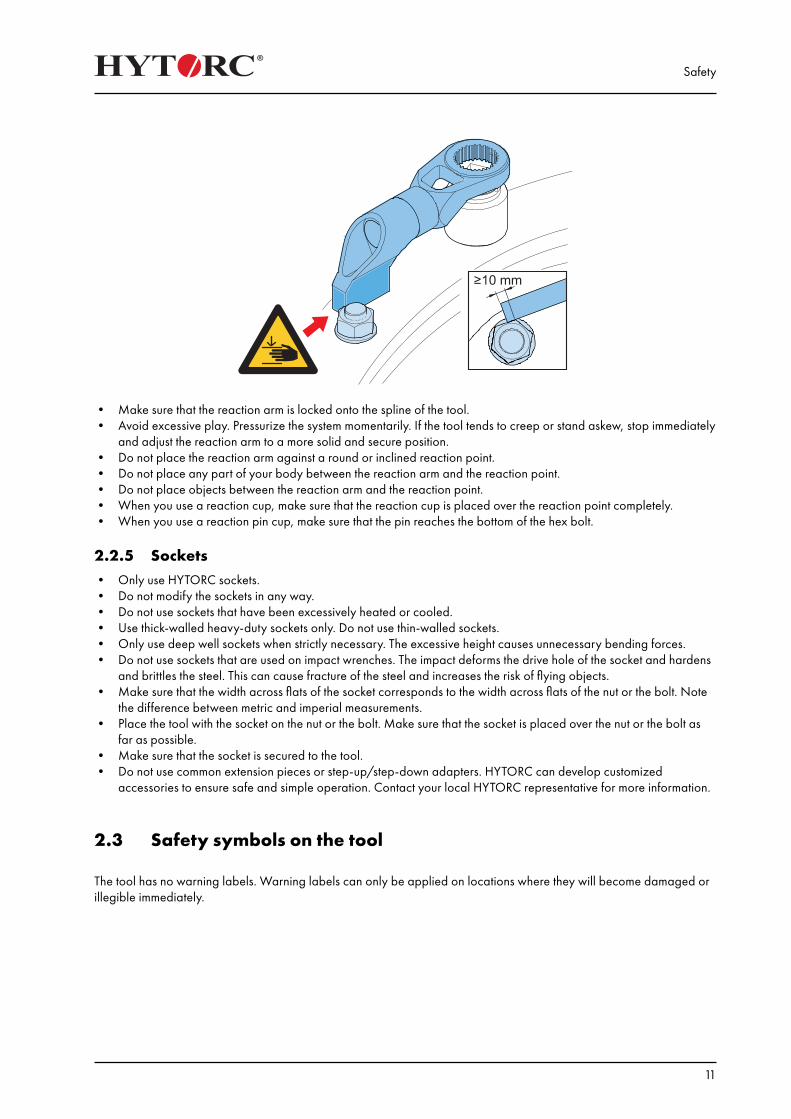
• Make sure that the reaction arm is locked onto the spline of the tool.• Avoid excessive play. Pressurize the system momentarily. If the tool tends to creep or stand askew, stop immediately
and adjust the reaction arm to a more solid and secure position.• Do not place the reaction arm against a round or inclined reaction point.• Do not place any part of your body between the reaction arm and the reaction point.• Do not place objects between the reaction arm and the reaction point.• When you use a reaction cup, make sure that the reaction cup is placed over the reaction point completely.• When you use a reaction pin cup, make sure that the pin reaches the bottom of the hex bolt.
2.2.5 Sockets• Only use HYTORC sockets.• Do not modify the sockets in any way.• Do not use sockets that have been excessively heated or cooled.• Use thick-walled heavy-duty sockets only. Do not use thin-walled sockets.• Only use deep well sockets when strictly necessary. The excessive height causes unnecessary bending forces.• Do not use sockets that are used on impact wrenches. The impact deforms the drive hole of the socket and hardens
and brittles the steel. This can cause fracture of the steel and increases the risk of flying objects.• Make sure that the width across flats of the socket corresponds to the width across flats of the nut or the bolt. Note
the difference between metric and imperial measurements.• Place the tool with the socket on the nut or the bolt. Make sure that the socket is placed over the nut or the bolt as
far as possible.• Make sure that the socket is secured to the tool.• Do not use common extension pieces or step-up/step-down adapters. HYTORC can develop customized
accessories to ensure safe and simple operation. Contact your local HYTORC representative for more information.
2.3 Safety symbols on the tool
The tool has no warning labels. Warning labels can only be applied on locations where they will become damaged or illegible immediately.
Safety
12
2.4 Qualified personnel
The term ‘qualified personnel’ refers to persons who thoroughly understand the equipment and its safe installation, operation and maintenance. Qualified personnel are physically capable of performing the required tasks, familiar with all relevant safety instructions and regulations and trained to safely install, operate and maintain the equipment. It is the responsibility of the company operating the equipment to see that the personnel meet these requirements.
2.5 Liability
HYTORC cannot be held responsible for injury or damage that results from unintended use of the equipment. The equipment is designed and intended only for the purpose described in the relevant documents. Uses not described in the relevant documents are considered unintended uses and can result in injury or damage.Unintended uses include:• Using equipment that is not approved by HYTORC• Using equipment that is inappropriate or incompatible with the HYTORC equipment• Altering or modifying equipment in any way• Allowing unqualified personnel to perform tasks on or with the equipment
Description
13
3. Description
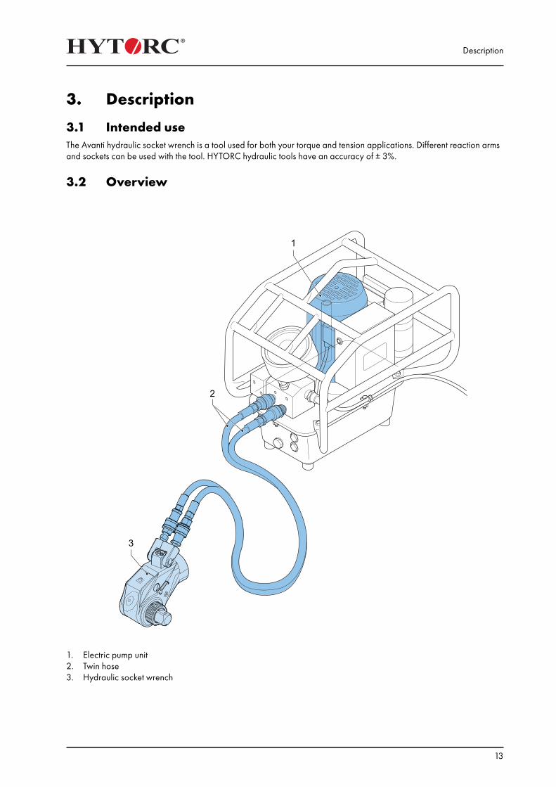
3.1 Intended useThe Avanti hydraulic socket wrench is a tool used for both your torque and tension applications. Different reaction arms and sockets can be used with the tool. HYTORC hydraulic tools have an accuracy of ± 3%.
3.2 Overview
1. Electric pump unit 2. Twin hose3. Hydraulic socket wrench
Description
14
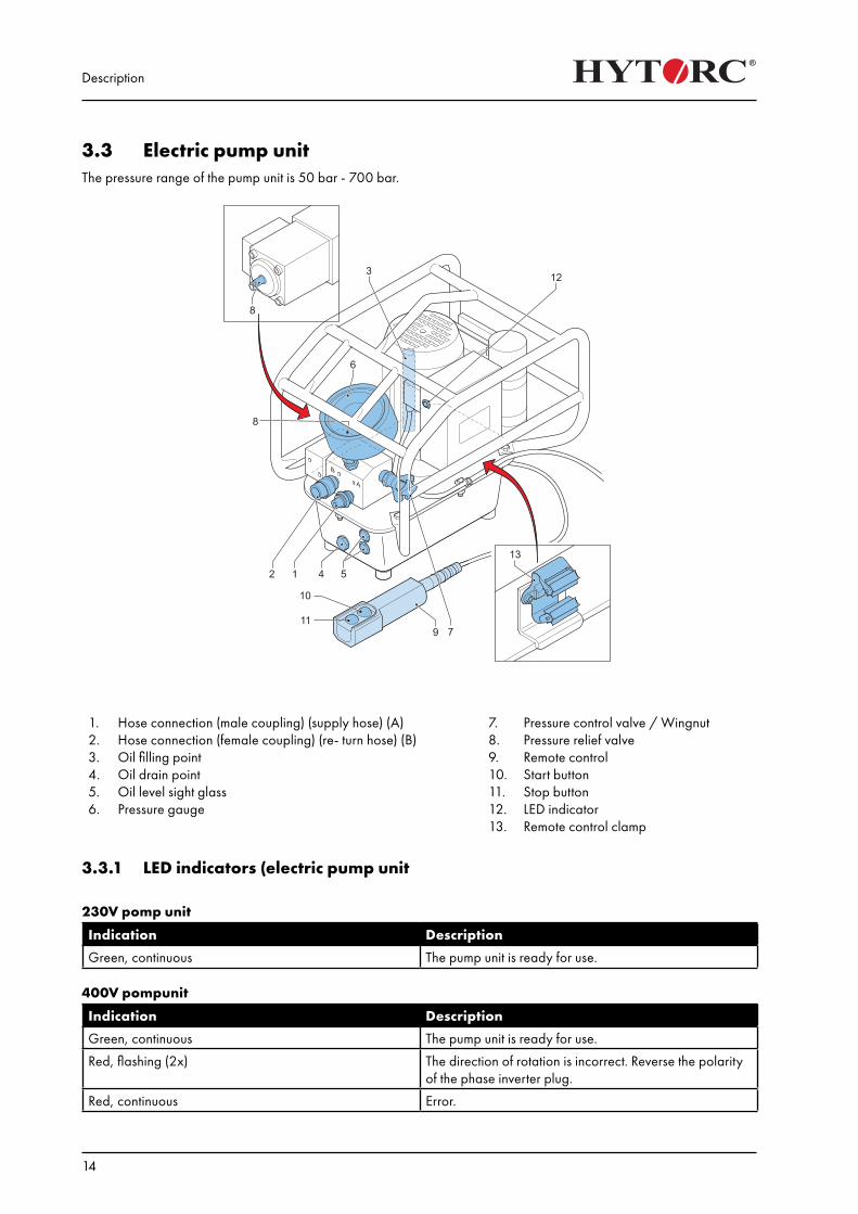
3.3 Electric pump unitThe pressure range of the pump unit is 50 bar - 700 bar.
1.2.3.4.5.6.
Hose connection (male coupling) (supply hose) (A)Hose connection (female coupling) (re- turn hose) (B)Oil filling pointOil drain pointOil level sight glass Pressure gauge
7.8.9.10.11.12.13.
Pressure control valve / WingnutPressure relief valveRemote controlStart buttonStop buttonLED indicatorRemote control clamp
3.3.1 LED indicators (electric pump unit
230V pomp unit
Indication Description
Green, continuous The pump unit is ready for use. 400V pompunit
Indication Description
Green, continuous The pump unit is ready for use.
Red, flashing (2x) The direction of rotation is incorrect. Reverse the polarity of the phase inverter plug.
Red, continuous Error.
Description
15
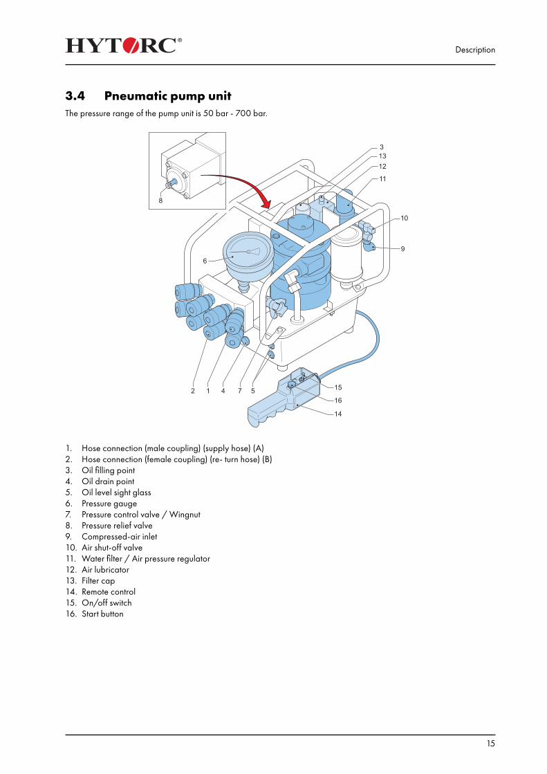
3.4 Pneumatic pump unitThe pressure range of the pump unit is 50 bar - 700 bar.
1. Hose connection (male coupling) (supply hose) (A)2. Hose connection (female coupling) (re- turn hose) (B)3. Oil filling point4. Oil drain point5. Oil level sight glass6. Pressure gauge7. Pressure control valve / Wingnut8. Pressure relief valve9. Compressed-air inlet10. Air shut-off valve11. Water filter / Air pressure regulator12. Air lubricator13. Filter cap14. Remote control15. On/off switch16. Start button
Description
16
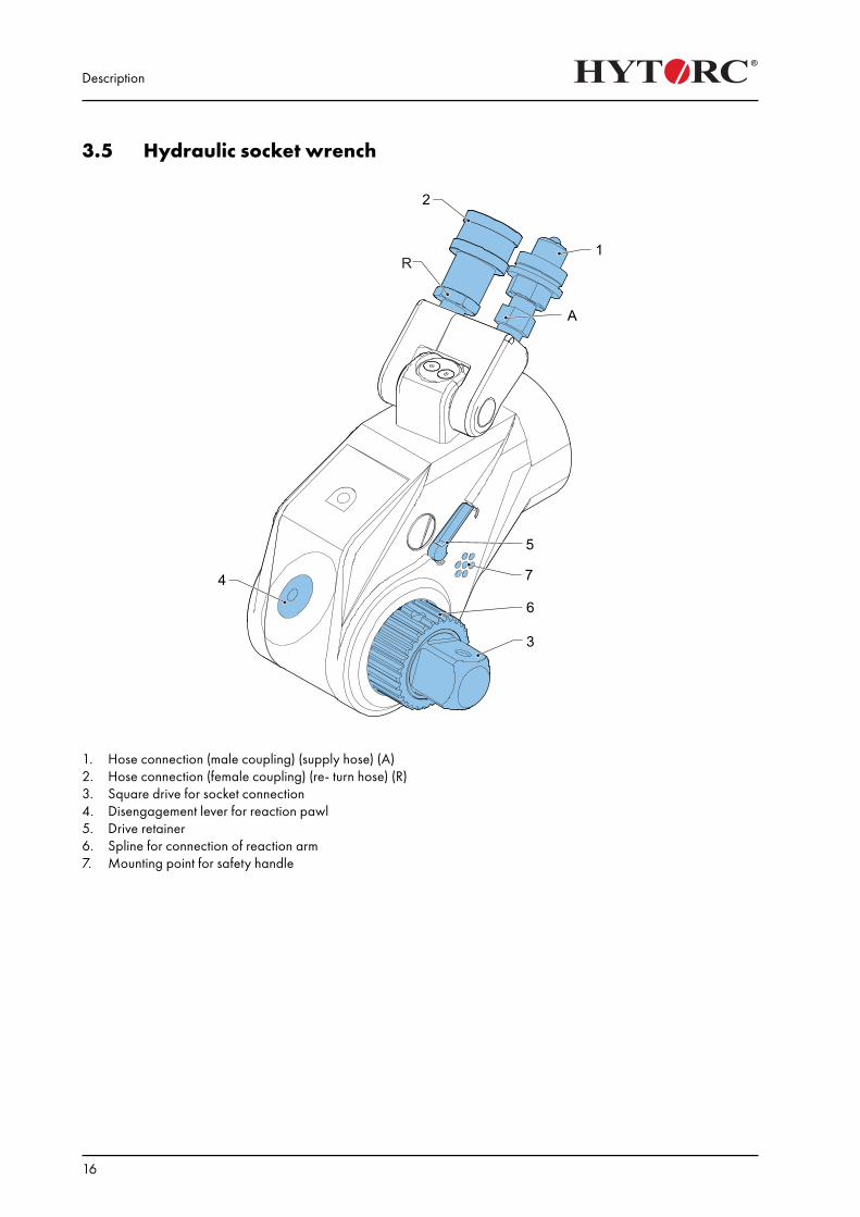
3.5 Hydraulic socket wrench
1. Hose connection (male coupling) (supply hose) (A)2. Hose connection (female coupling) (re- turn hose) (R)3. Square drive for socket connection4. Disengagement lever for reaction pawl5. Drive retainer6. Spline for connection of reaction arm7. Mounting point for safety handle
Description
17
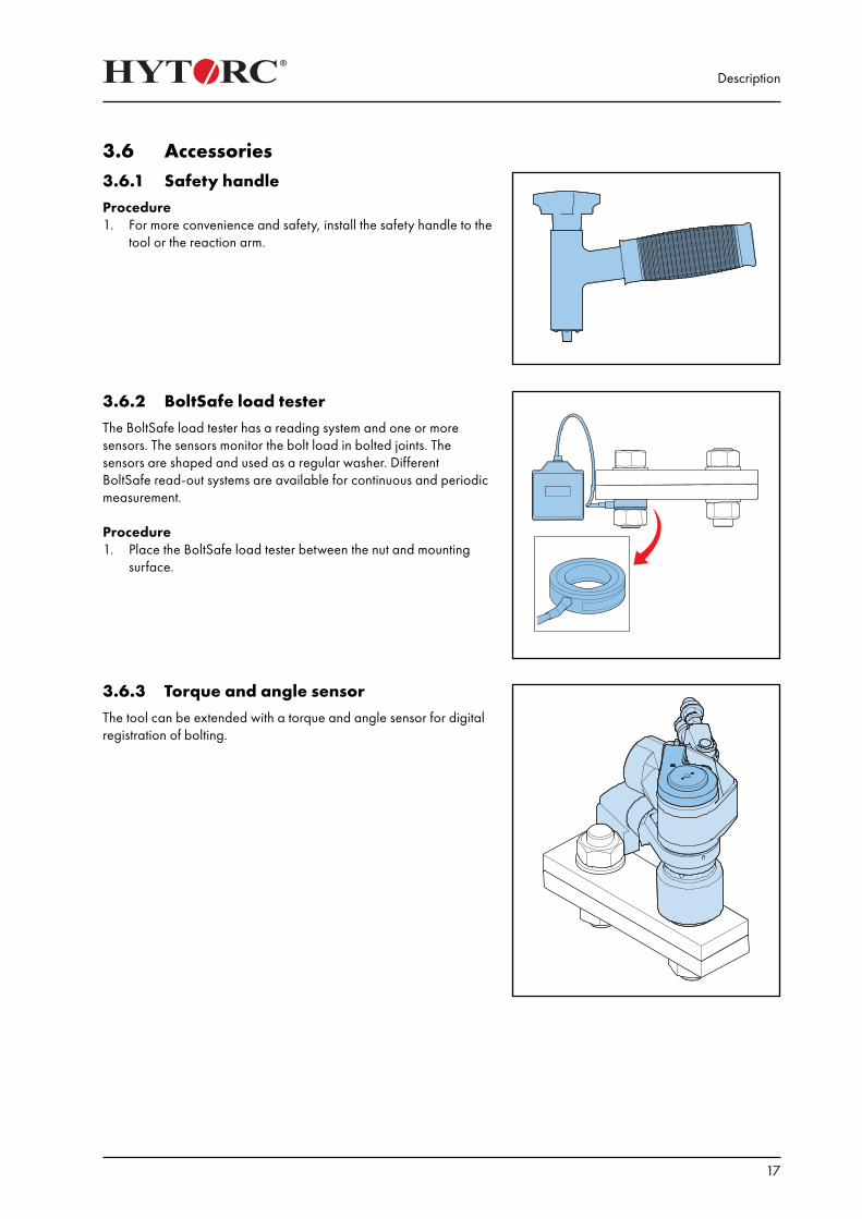
3.6 Accessories3.6.1 Safety handleProcedure1. For more convenience and safety, install the safety handle to the
tool or the reaction arm.
3.6.2 BoltSafe load testerThe BoltSafe load tester has a reading system and one or more sensors. The sensors monitor the bolt load in bolted joints. The sensors are shaped and used as a regular washer. Different BoltSafe read-out systems are available for continuous and periodic measurement.
Procedure1. Place the BoltSafe load tester between the nut and mounting
surface.
3.6.3 Torque and angle sensorThe tool can be extended with a torque and angle sensor for digital registration of bolting.

Description
18
Installation
19
4. Installation
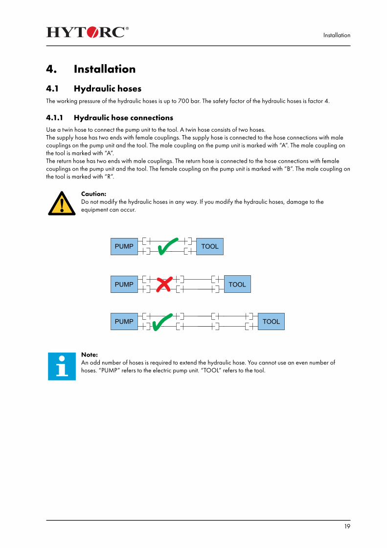
4.1 Hydraulic hosesThe working pressure of the hydraulic hoses is up to 700 bar. The safety factor of the hydraulic hoses is factor 4. 4.1.1 Hydraulic hose connectionsUse a twin hose to connect the pump unit to the tool. A twin hose consists of two hoses.The supply hose has two ends with female couplings. The supply hose is connected to the hose connections with male couplings on the pump unit and the tool. The male coupling on the pump unit is marked with “A”. The male coupling on the tool is marked with “A”.The return hose has two ends with male couplings. The return hose is connected to the hose connections with female couplings on the pump unit and the tool. The female coupling on the pump unit is marked with “B”. The male coupling on the tool is marked with “R”.
Caution:Do not modify the hydraulic hoses in any way. If you modify the hydraulic hoses, damage to the equipment can occur.
Note: An odd number of hoses is required to extend the hydraulic hose. You cannot use an even number of hoses. “PUMP” refers to the electric pump unit. “TOOL” refers to the tool.
Installation
20
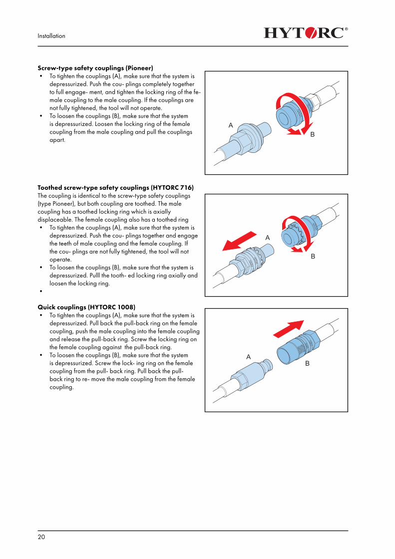
Screw-type safety couplings (Pioneer)• To tighten the couplings (A), make sure that the system is
depressurized. Push the cou- plings completely together to full engage- ment, and tighten the locking ring of the fe- male coupling to the male coupling. If the couplings are not fully tightened, the tool will not operate.
• To loosen the couplings (B), make sure that the system is depressurized. Loosen the locking ring of the female coupling from the male coupling and pull the couplings apart.
Toothed screw-type safety couplings (HYTORC 716)The coupling is identical to the screw-type safety couplings (type Pioneer), but both coupling are toothed. The male coupling has a toothed locking ring which is axially displaceable. The female coupling also has a toothed ring• To tighten the couplings (A), make sure that the system is
depressurized. Push the cou- plings together and engage the teeth of male coupling and the female coupling. If the cou- plings are not fully tightened, the tool will not operate.
• To loosen the couplings (B), make sure that the system is depressurized. Pulll the tooth- ed locking ring axially and loosen the locking ring.
•
Quick couplings (HYTORC 1008)• To tighten the couplings (A), make sure that the system is
depressurized. Pull back the pull-back ring on the female coupling, push the male coupling into the female coupling and release the pull-back ring. Screw the locking ring on the female coupling against the pull-back ring.
• To loosen the couplings (B), make sure that the system is depressurized. Screw the lock- ing ring on the female coupling from the pull- back ring. Pull back the pull-back ring to re- move the male coupling from the female coupling.
Installation
21
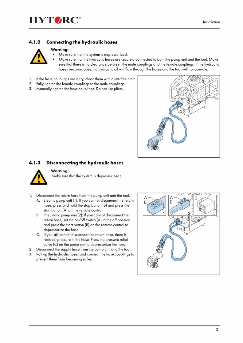
4.1.2 Connecting the hydraulic hosesWarning:• Make sure that the system is depressurized.• Make sure that the hydraulic hoses are securely connected to both the pump unit and the tool. Make
sure that there is no clearance between the male couplings and the female couplings. If the hydraulic hoses become loose, no hydraulic oil will flow through the hoses and the tool will not operate.
1. If the hose couplings are dirty, clean them with a lint-free cloth.2. Fully tighten the female couplings to the male couplings.3. Manually tighten the hose couplings. Do not use pliers.
4.1.3 Disconnecting the hydraulic hoses
Warning:Make sure that the system is depressurized.t.
1. Disconnect the return hose from the pump unit and the tool.A. Electric pump unit (1): If you cannot disconnect the return
hose, press and hold the stop button (B) and press the start button (A) on the remote control.
B. Pneumatic pump unit (2): If you cannot disconnect the return hose, set the on/off switch (A) to the off position and press the start button (B) on the remote control to depressurize the hose.
C. If you still cannot disconnect the return hose, there is residual pressure in the hose. Press the pressure relief valve (C) on the pump unit to depressurize the hose.
2. Disconnect the supply hose from the pump unit and the tool.3. Roll up the hydraulic hoses and connect the hose couplings to
prevent them from becoming soiled.
Installation
22
4.2 Power supply (electric pump units)There are different types of electric pump units to operate the tool:1. 230V pump unit2. 400V pump unit
Warning:• Do not use an extension cable longer than necessary.• Make sure that the length of the extension cable does not exceed 50 metres.• Make sure that the cross section of the wires in the extension cable is at least 2.5 mm2.• Fully unroll the extension cable from the cable drum
4.2.1 Connecting the power supply (230V)1. Connect the mains plug to the wall socket.2. Make sure that the cross section of the wires in the extension
cable is at least 2.5 mm2).
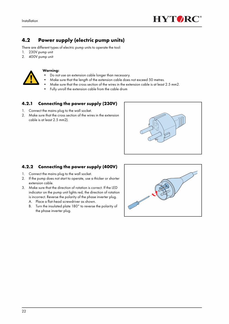
4.2.2 Connecting the power supply (400V)1. Connect the mains plug to the wall socket.2. If the pump does not start to operate, use a thicker or shorter
extension cable.3. Make sure that the direction of rotation is correct. If the LED
indicator on the pump unit lights red, the direction of rotation is incorrect. Reverse the polarity of the phase inverter plug.A. Place a flat-head screwdriver as shown.B. Turn the insulated plate 180° to reverse the polarity of
the phase inverter plug.
Installation
23
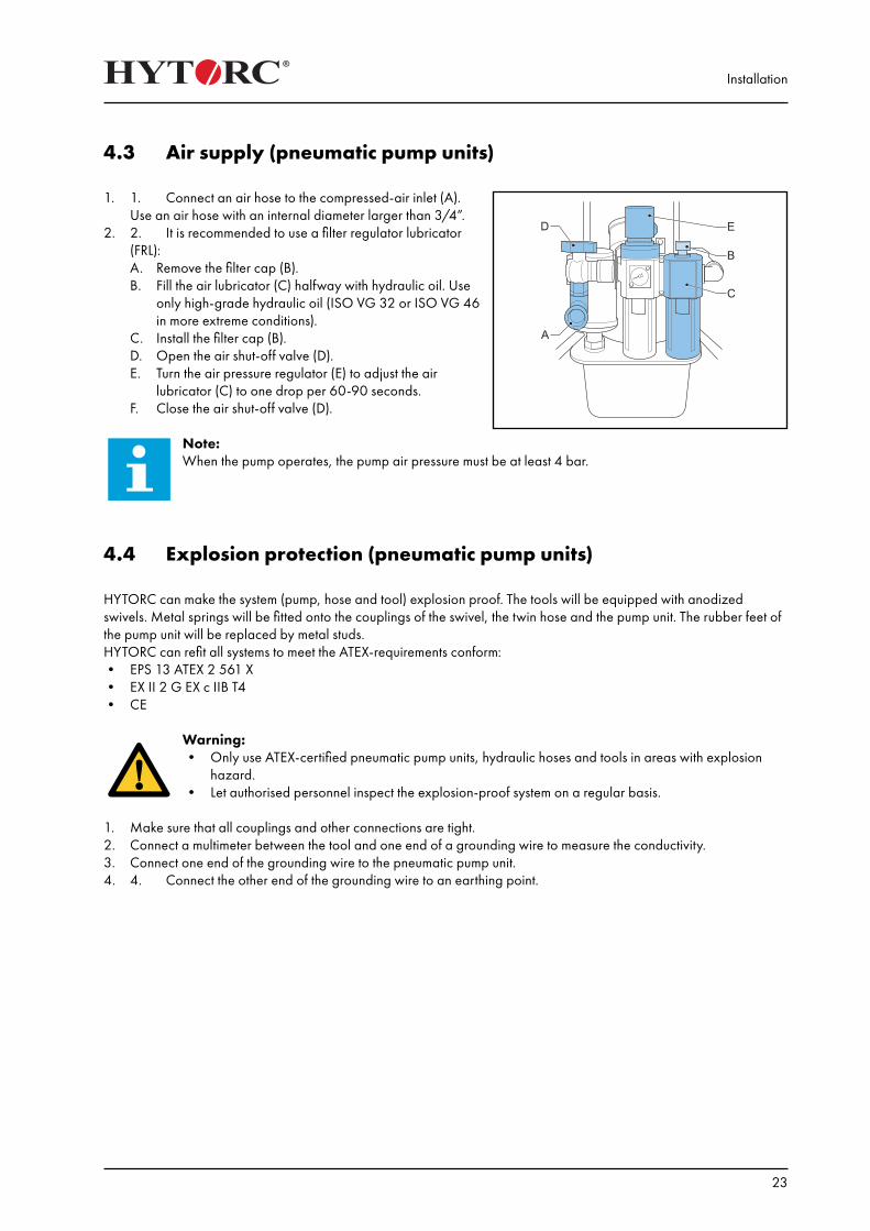
4.3 Air supply (pneumatic pump units)
1. 1. Connect an air hose to the compressed-air inlet (A). Use an air hose with an internal diameter larger than 3/4”.
2. 2. It is recommended to use a filter regulator lubricator (FRL):A. Remove the filter cap (B).B. Fill the air lubricator (C) halfway with hydraulic oil. Use
only high-grade hydraulic oil (ISO VG 32 or ISO VG 46 in more extreme conditions).
C. Install the filter cap (B).D. Open the air shut-off valve (D).E. Turn the air pressure regulator (E) to adjust the air
lubricator (C) to one drop per 60-90 seconds.F. Close the air shut-off valve (D).
Note: When the pump operates, the pump air pressure must be at least 4 bar.
4.4 Explosion protection (pneumatic pump units)
HYTORC can make the system (pump, hose and tool) explosion proof. The tools will be equipped with anodized swivels. Metal springs will be fitted onto the couplings of the swivel, the twin hose and the pump unit. The rubber feet of the pump unit will be replaced by metal studs.HYTORC can refit all systems to meet the ATEX-requirements conform:• EPS 13 ATEX 2 561 X• EX II 2 G EX c IIB T4• CE
Warning:• Only use ATEX-certified pneumatic pump units, hydraulic hoses and tools in areas with explosion
hazard.• Let authorised personnel inspect the explosion-proof system on a regular basis.
1. Make sure that all couplings and other connections are tight.2. Connect a multimeter between the tool and one end of a grounding wire to measure the conductivity.3. Connect one end of the grounding wire to the pneumatic pump unit.4. 4. Connect the other end of the grounding wire to an earthing point.

Installation
24
Reaction arms
25
5. Reaction armsThe reaction arms can be used together with hydraulic tools, pneumatic tools and electric tools.There are different types of reaction arms to operate the tool.
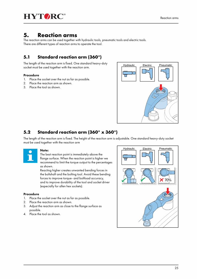
5.1 Standard reaction arm (360°)The length of the reaction arm is fixed. One standard heavy-duty socket must be used together with the reaction arm.
Procedure1. Place the socket over the nut as far as possible.2. Place the reaction arm as shown.3. Place the tool as shown.
5.2 Standard reaction arm (360° x 360°)The length of the reaction arm is fixed. The height of the reaction arm is adjustable. One standard heavy-duty socket must be used together with the reaction arm
Note:The best reaction point is immediately above the flange surface. When the reaction point is higher we recommend to limit the torque output to the percentages as shown.Reacting higher creates unwanted bending forces in the boltshaft and the bolting tool. Avoid these bending forces to improve torque- and boltload accuracy, and to improve durability of the tool and socket driver (especially for allen hex sockets).
Procedure1. Place the socket over the nut as far as possible.2. Place the reaction arm as shown.3. Adjust the reaction arm as close to the flange surface as
possible.4. Place the tool as shown.
Reaction arms
26
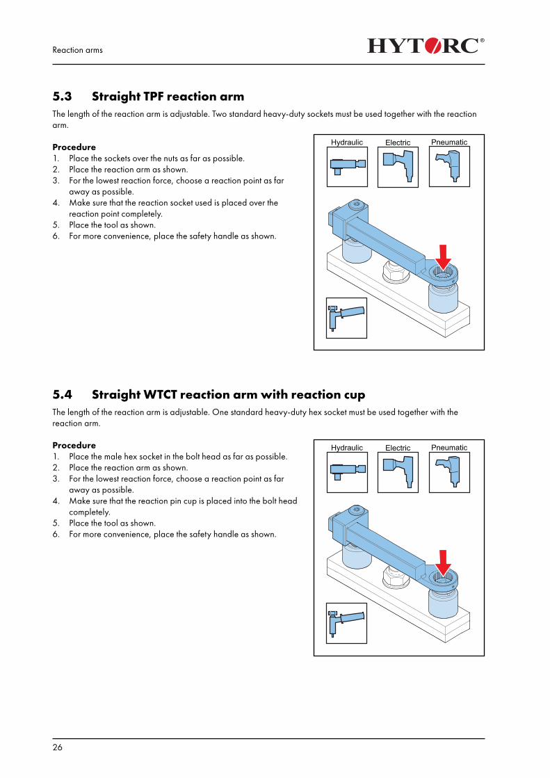
5.3 Straight TPF reaction armThe length of the reaction arm is adjustable. Two standard heavy-duty sockets must be used together with the reaction arm.
Procedure1. Place the sockets over the nuts as far as possible.2. Place the reaction arm as shown.3. For the lowest reaction force, choose a reaction point as far
away as possible.4. Make sure that the reaction socket used is placed over the
reaction point completely.5. Place the tool as shown.6. For more convenience, place the safety handle as shown.
5.4 Straight WTCT reaction arm with reaction cupThe length of the reaction arm is adjustable. One standard heavy-duty hex socket must be used together with the reaction arm.
Procedure1. Place the male hex socket in the bolt head as far as possible.2. Place the reaction arm as shown.3. For the lowest reaction force, choose a reaction point as far
away as possible.4. Make sure that the reaction pin cup is placed into the bolt head
completely.5. Place the tool as shown.6. For more convenience, place the safety handle as shown.
Reaction arms
27
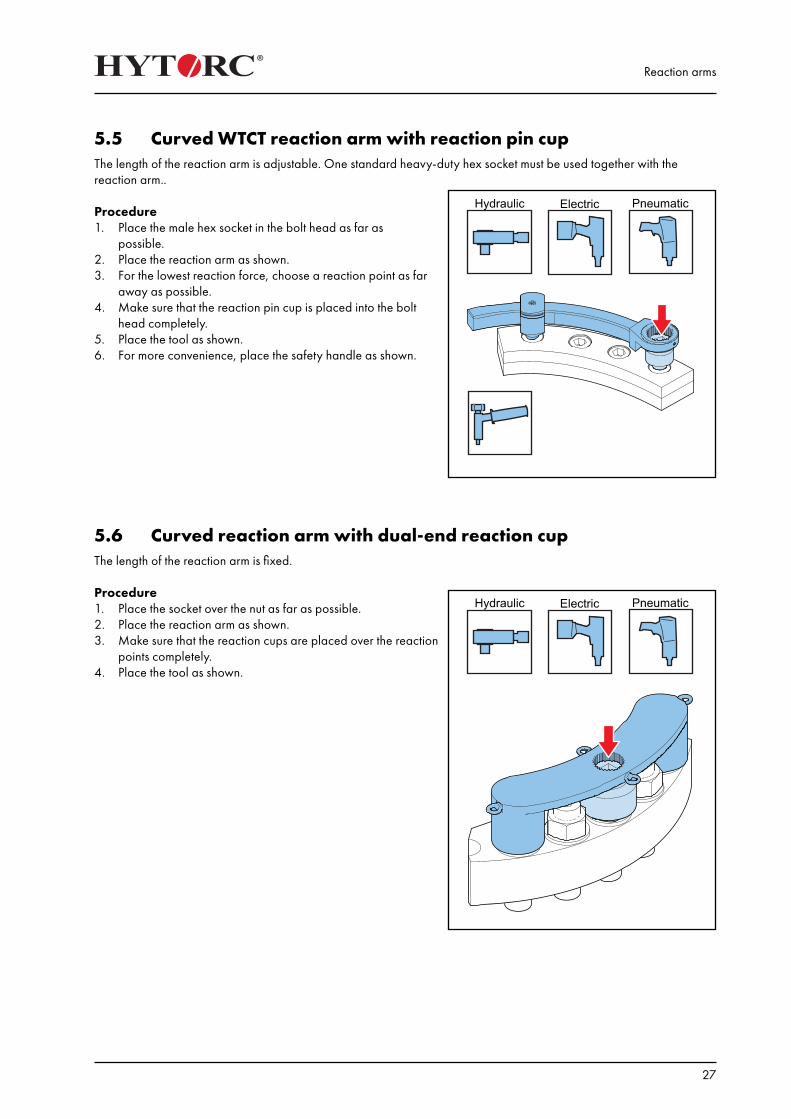
5.5 Curved WTCT reaction arm with reaction pin cupThe length of the reaction arm is adjustable. One standard heavy-duty hex socket must be used together with the reaction arm..
Procedure1. Place the male hex socket in the bolt head as far as
possible.2. Place the reaction arm as shown.3. For the lowest reaction force, choose a reaction point as far
away as possible.4. Make sure that the reaction pin cup is placed into the bolt
head completely.5. Place the tool as shown.6. For more convenience, place the safety handle as shown.
5.6 Curved reaction arm with dual-end reaction cupThe length of the reaction arm is fixed.
Procedure1. Place the socket over the nut as far as possible.2. Place the reaction arm as shown.3. Make sure that the reaction cups are placed over the reaction
points completely.4. Place the tool as shown.
Reaction arms
28
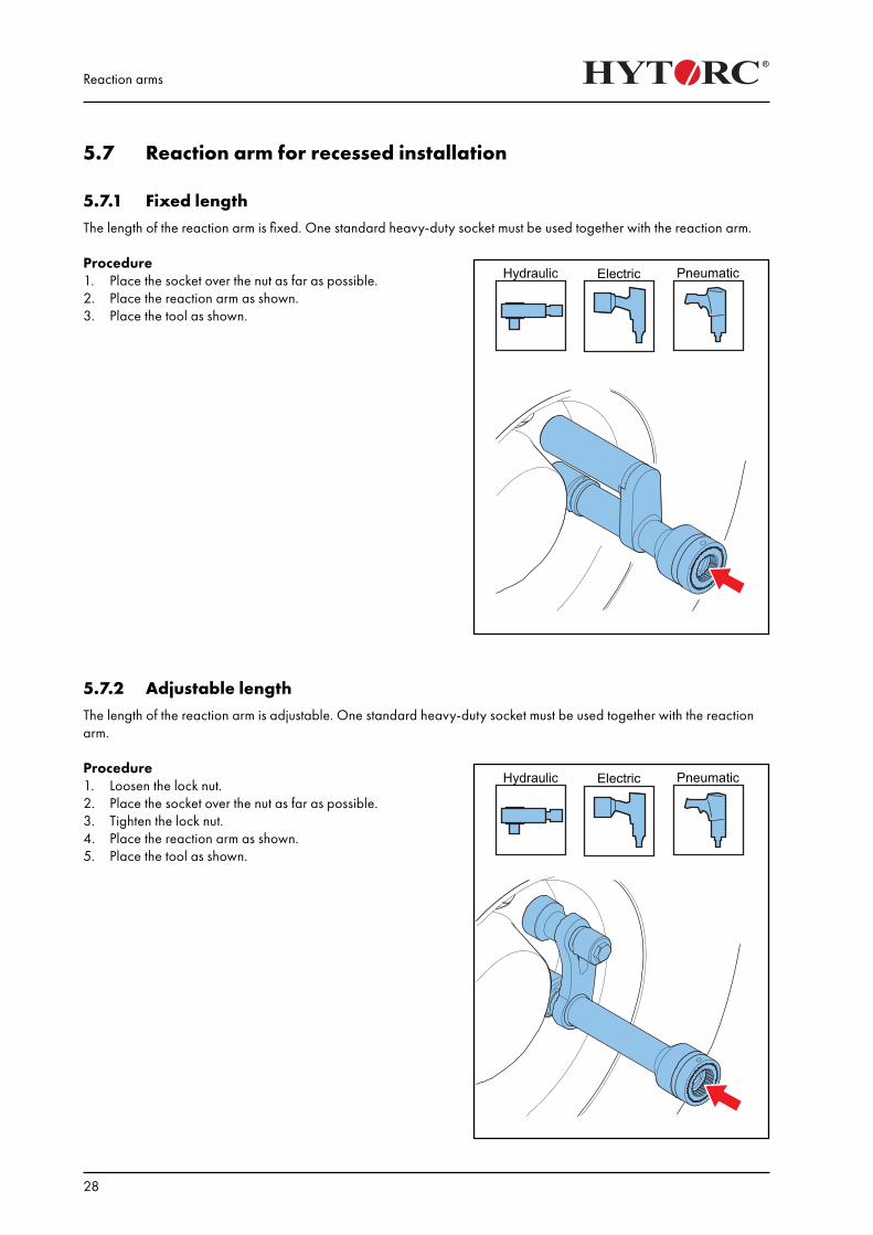
5.7 Reaction arm for recessed installation
5.7.1 Fixed lengthThe length of the reaction arm is fixed. One standard heavy-duty socket must be used together with the reaction arm.
Procedure1. Place the socket over the nut as far as possible.2. Place the reaction arm as shown.3. Place the tool as shown.
5.7.2 Adjustable lengthThe length of the reaction arm is adjustable. One standard heavy-duty socket must be used together with the reaction arm.
Procedure1. Loosen the lock nut.2. Place the socket over the nut as far as possible.3. Tighten the lock nut.4. Place the reaction arm as shown.5. Place the tool as shown.
Reaction arms
29
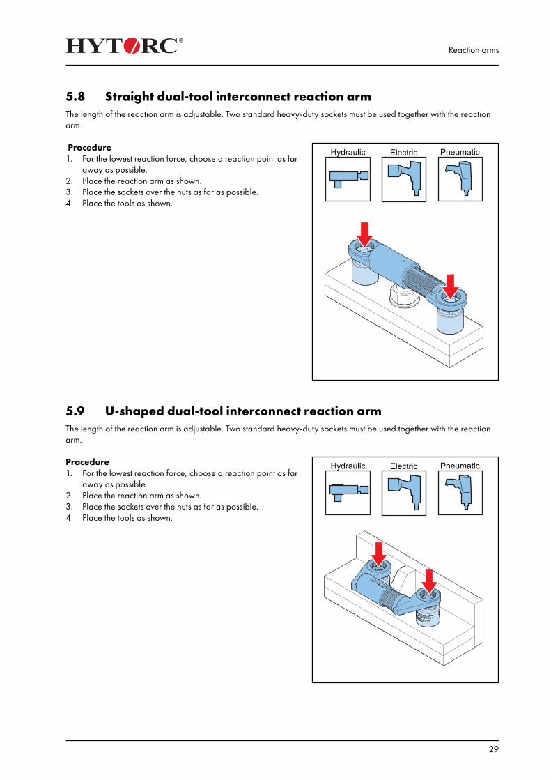
5.8 Straight dual-tool interconnect reaction armThe length of the reaction arm is adjustable. Two standard heavy-duty sockets must be used together with the reaction arm.
Procedure1. For the lowest reaction force, choose a reaction point as far
away as possible.2. Place the reaction arm as shown.3. Place the sockets over the nuts as far as possible.4. Place the tools as shown.
5.9 U-shaped dual-tool interconnect reaction armThe length of the reaction arm is adjustable. Two standard heavy-duty sockets must be used together with the reaction arm.
Procedure1. For the lowest reaction force, choose a reaction point as far
away as possible.2. Place the reaction arm as shown.3. Place the sockets over the nuts as far as possible.4. Place the tools as shown.
Reaction arms
30
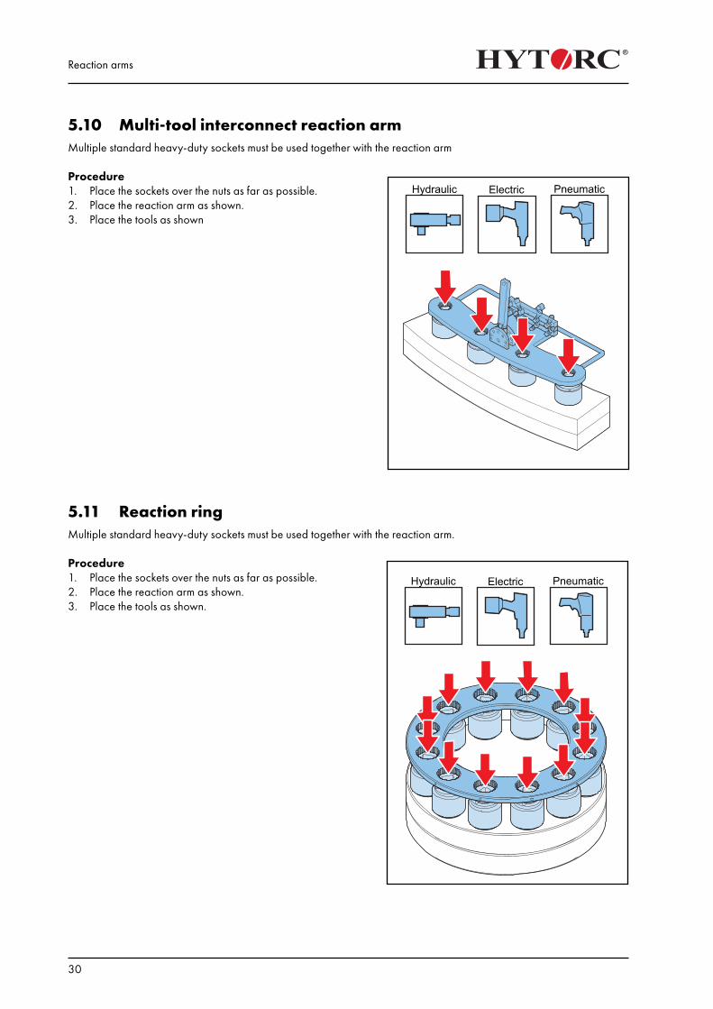
5.10 Multi-tool interconnect reaction armMultiple standard heavy-duty sockets must be used together with the reaction arm
Procedure1. Place the sockets over the nuts as far as possible.2. Place the reaction arm as shown.3. Place the tools as shown
5.11 Reaction ringMultiple standard heavy-duty sockets must be used together with the reaction arm.
Procedure1. Place the sockets over the nuts as far as possible.2. Place the reaction arm as shown.3. Place the tools as shown.
Reaction arms
31
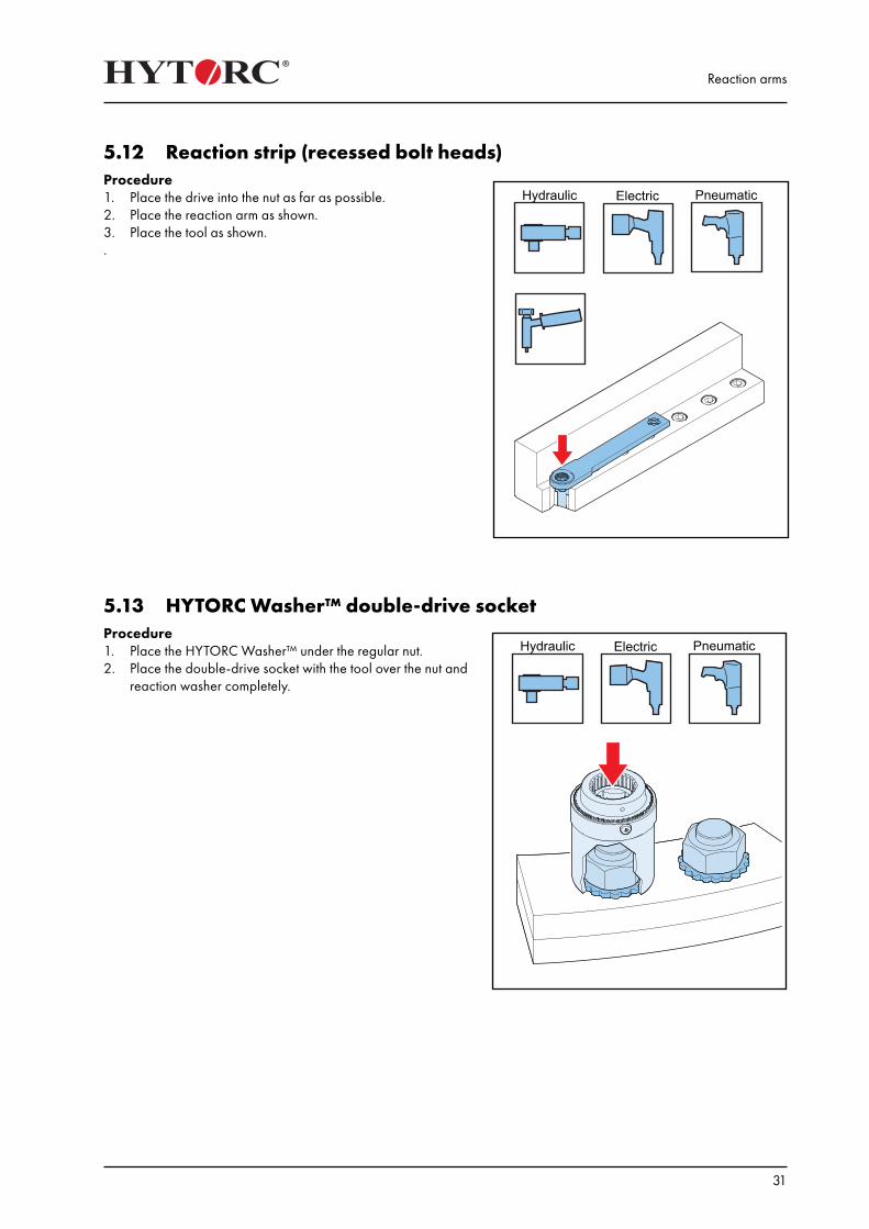
5.12 Reaction strip (recessed bolt heads)Procedure1. Place the drive into the nut as far as possible.2. Place the reaction arm as shown.3. Place the tool as shown..
5.13 HYTORC Washer™ double-drive socketProcedure1. Place the HYTORC Washer™ under the regular nut.2. Place the double-drive socket with the tool over the nut and
reaction washer completely.
Reaction arms
32
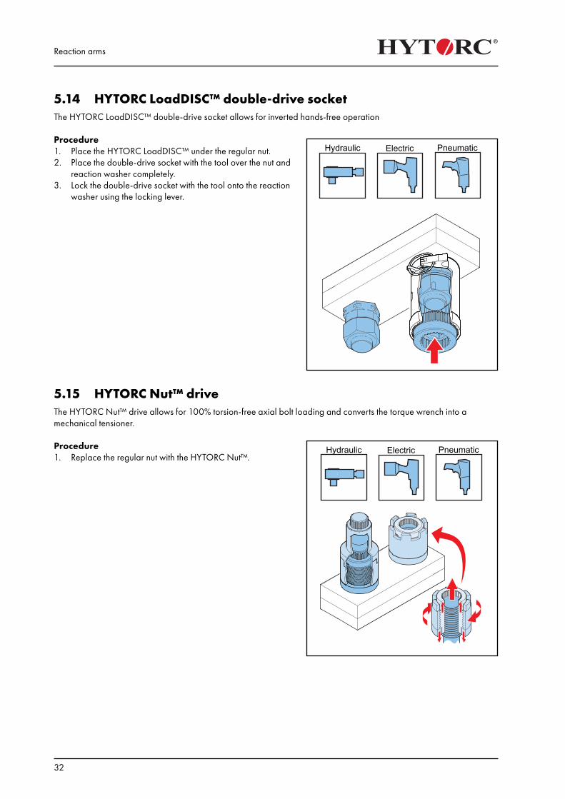
5.14 HYTORC LoadDISC™ double-drive socket The HYTORC LoadDISC™ double-drive socket allows for inverted hands-free operation
Procedure1. Place the HYTORC LoadDISC™ under the regular nut.2. Place the double-drive socket with the tool over the nut and
reaction washer completely.3. Lock the double-drive socket with the tool onto the reaction
washer using the locking lever.
5.15 HYTORC Nut™ driveThe HYTORC Nut™ drive allows for 100% torsion-free axial bolt loading and converts the torque wrench into a mechanical tensioner.
Procedure1. Replace the regular nut with the HYTORC Nut™.
Reaction arms
33
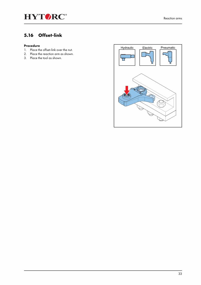
5.16 Offset-link
Procedure1. Place the offset-link over the nut.2. Place the reaction arm as shown.3. Place the tool as shown.

Reaction arms
34
Securing the sockets and reaction arms
35
6. Securing the sockets and reaction armsSockets and reaction arms must be secured to prevent injuries and damage to the equipment.
There are different types of heavy-duty sockets to use with the tool:1. 6-point sockets / 12-point sockets (regular / high)2. 6-point hex sockets / 12-point hex sockets (regular / high)3. Eccentric sockets4. Customized socketsThe heavy-duty sockets are available in the sizes 1/2”, 3/4”, 1”, 1 1/2”, 2 1/2” and 3 1/2
Warning:• Do not use sockets that are used on impact wrenches.
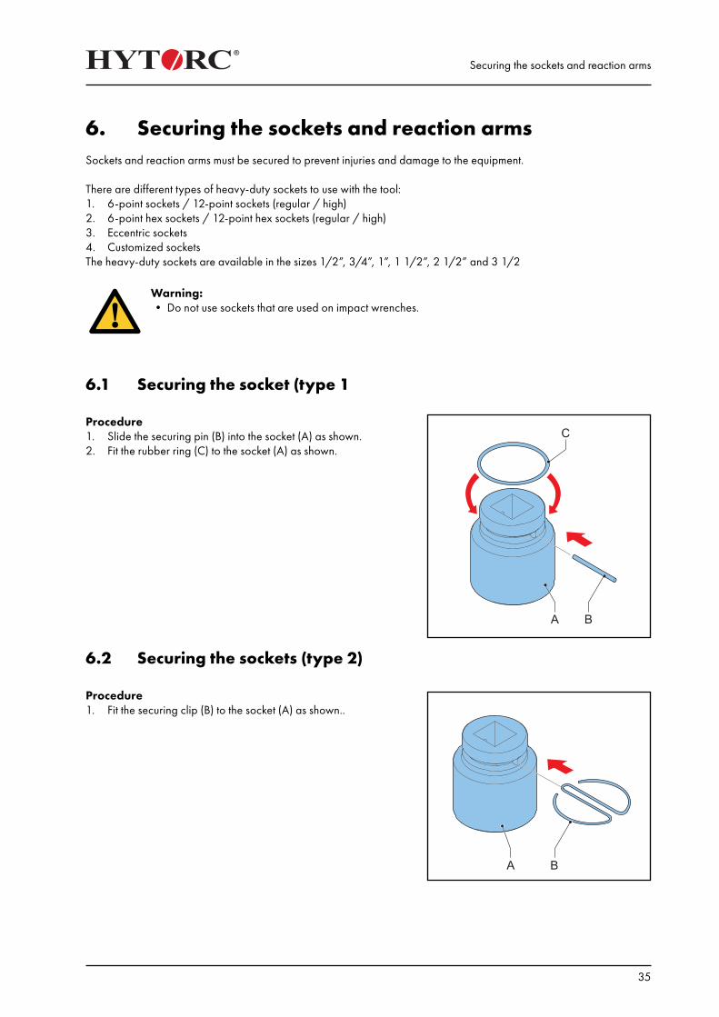
6.1 Securing the socket (type 1
Procedure1. Slide the securing pin (B) into the socket (A) as shown.2. Fit the rubber ring (C) to the socket (A) as shown.
6.2 Securing the sockets (type 2)
Procedure1. Fit the securing clip (B) to the socket (A) as shown..
Securing the sockets and reaction arms
36
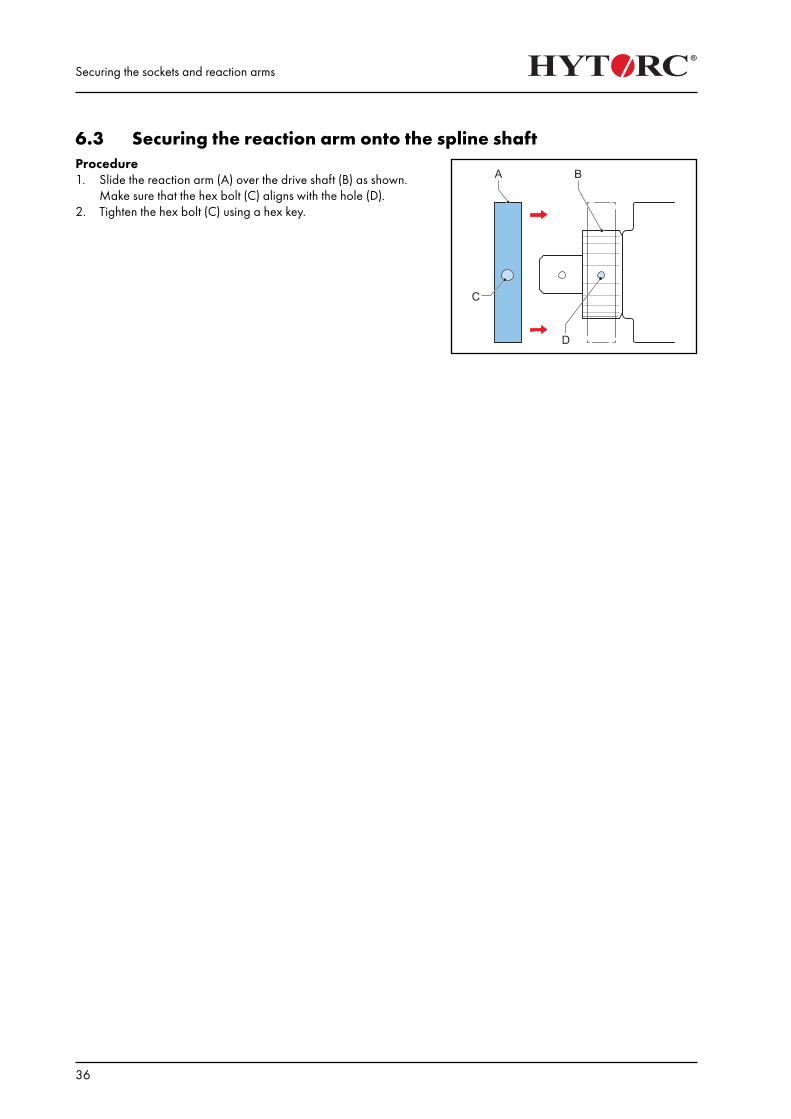
6.3 Securing the reaction arm onto the spline shaftProcedure1. Slide the reaction arm (A) over the drive shaft (B) as shown.
Make sure that the hex bolt (C) aligns with the hole (D).2. Tighten the hex bolt (C) using a hex key.
Operation
37
7. Operation
7.1 Inspections before useMake sure that:• the oil level in the oil tank is beween the minimum mark and the maximum mark.• the power supply is correct.• the power cable is fully unrolled and not kinked, twisted or damaged.• the remote control cable is fully unrolled and not kinked, twisted or damaged.• all couplings and other connections are tight and not damaged or deformed.• the hydraulic hoses are securely connected and not kinked, twisted or damaged. Inspect the hydraulic hoses for
damage with a set pressure of 200 bar (2,900 psi), 400 bar (5,800 psi) and 700 bar (10,000 psi) respectively.• all moving parts of the tool are clean and sufficiently lubricated with a high-quality NLGI #2 molybdenum disulfide
grease. For subsea applications, HYTORC recommends Womi lube.• the square drive and the drive retainer are securely fitted.• the reaction arm is placed against a solid reaction point and secured to the tool.• the socket has the correct size and is secured to the tool.• all securing clips, securing pins and securing screws are fitted and secured to the pump unit, the hydraulic hoses,
the tool, the reaction arm and the socket.• all water, if present, is drained from the water separator (pneumatic pump units only).• the pressure gauge does not leak. Signs of leakage are a decrease in the level of glycerin in the pressure gauge or
the pressure gauge filled with hydraulic oil.
7.2 Remote control
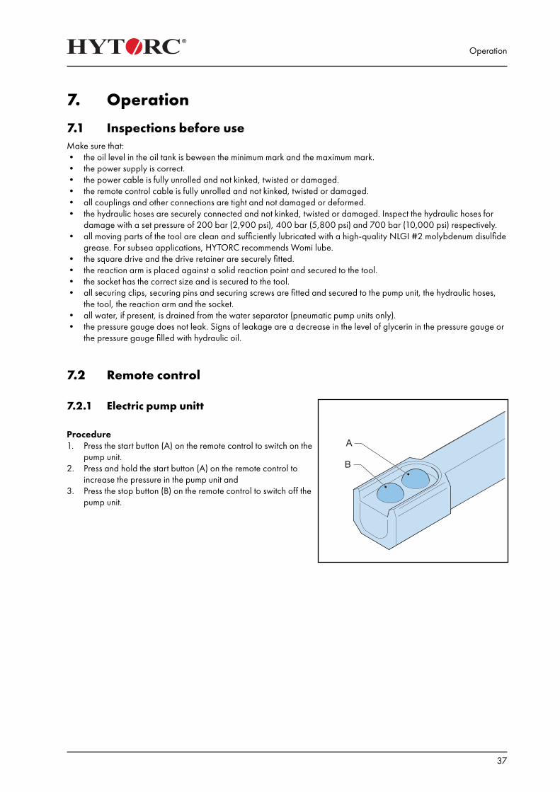
7.2.1 Electric pump unitt
Procedure1. Press the start button (A) on the remote control to switch on the
pump unit.2. Press and hold the start button (A) on the remote control to
increase the pressure in the pump unit and3. Press the stop button (B) on the remote control to switch off the
pump unit.
Operation
38
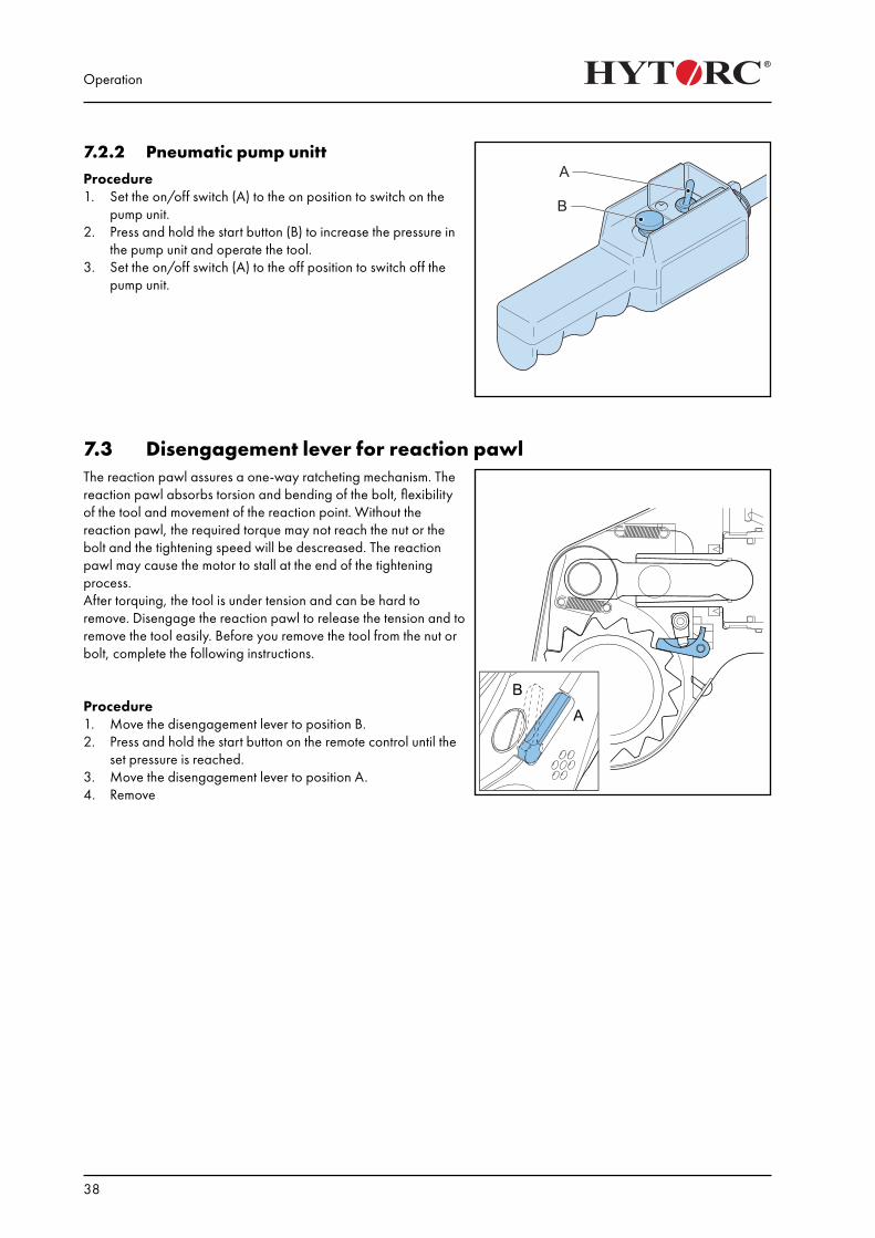
7.2.2 Pneumatic pump unittProcedure1. Set the on/off switch (A) to the on position to switch on the
pump unit.2. Press and hold the start button (B) to increase the pressure in
the pump unit and operate the tool.3. Set the on/off switch (A) to the off position to switch off the
pump unit.
7.3 Disengagement lever for reaction pawlThe reaction pawl assures a one-way ratcheting mechanism. The reaction pawl absorbs torsion and bending of the bolt, flexibility of the tool and movement of the reaction point. Without the reaction pawl, the required torque may not reach the nut or the bolt and the tightening speed will be descreased. The reaction pawl may cause the motor to stall at the end of the tightening process.After torquing, the tool is under tension and can be hard to remove. Disengage the reaction pawl to release the tension and to remove the tool easily. Before you remove the tool from the nut or bolt, complete the following instructions.
Procedure1. Move the disengagement lever to position B.2. Press and hold the start button on the remote control until the
set pressure is reached.3. Move the disengagement lever to position A.4. Remove
Operation
39
7.4 Torque
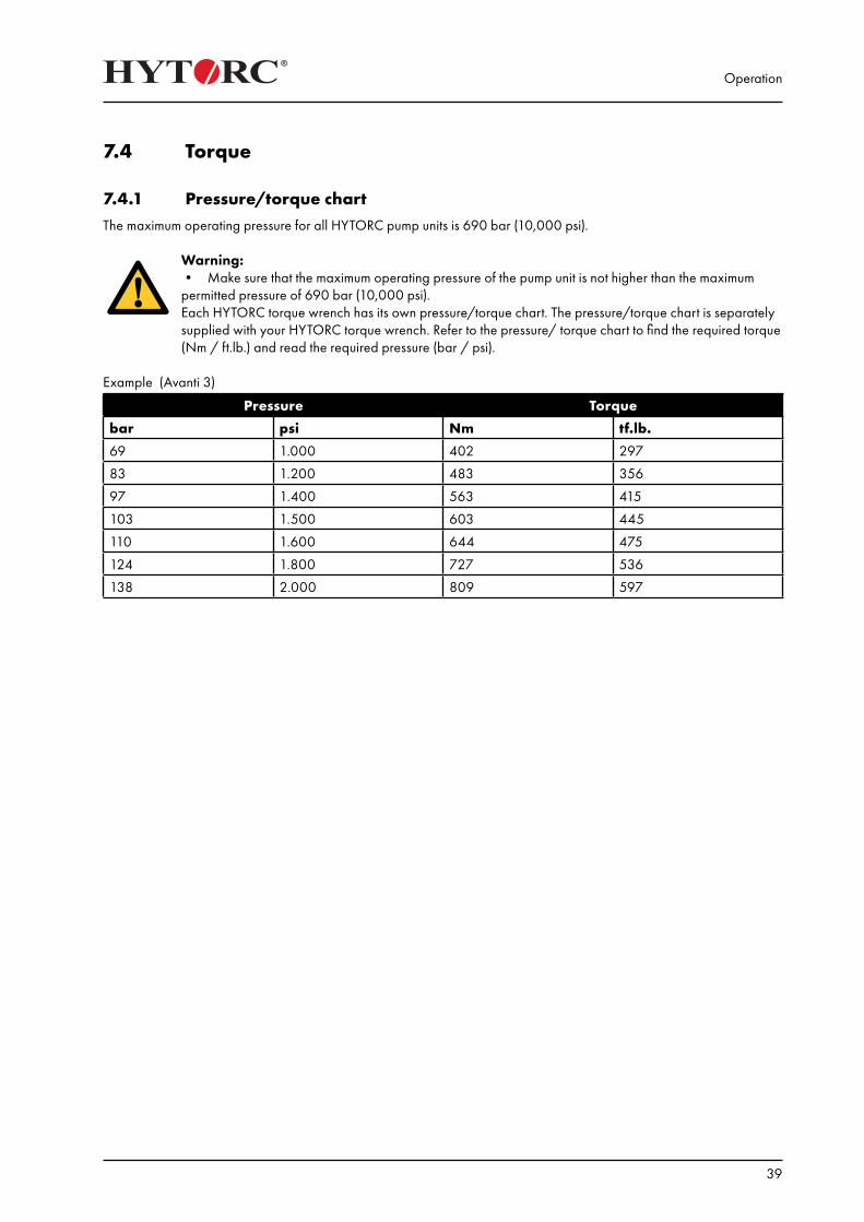
7.4.1 Pressure/torque chartThe maximum operating pressure for all HYTORC pump units is 690 bar (10,000 psi).
Warning: • Make sure that the maximum operating pressure of the pump unit is not higher than the maximum permitted pressure of 690 bar (10,000 psi).Each HYTORC torque wrench has its own pressure/torque chart. The pressure/torque chart is separately supplied with your HYTORC torque wrench. Refer to the pressure/ torque chart to find the required torque (Nm / ft.lb.) and read the required pressure (bar / psi).
Example (Avanti 3)
Pressure Torque
bar psi Nm tf.lb.
69 1.000 402 297
83 1.200 483 356
97 1.400 563 415
103 1.500 603 445
110 1.600 644 475
124 1.800 727 536
138 2.000 809 597
Operation
40
7.4.2 Setting the torque
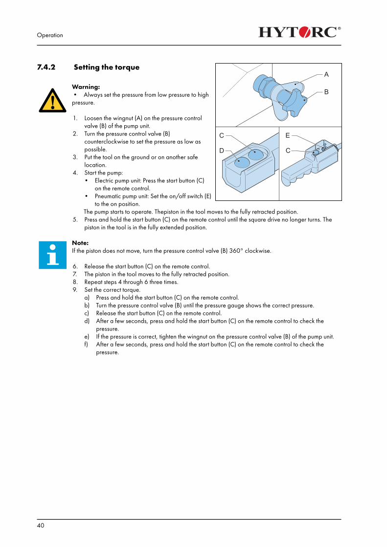
Warning:• Always set the pressure from low pressure to high pressure.
1. Loosen the wingnut (A) on the pressure control valve (B) of the pump unit.
2. Turn the pressure control valve (B) counterclockwise to set the pressure as low as possible.
3. Put the tool on the ground or on another safe location.
4. Start the pump:• Electric pump unit: Press the start button (C)
on the remote control.• Pneumatic pump unit: Set the on/off switch (E)
to the on position. The pump starts to operate. Thepiston in the tool moves to the fully retracted position.5. Press and hold the start button (C) on the remote control until the square drive no longer turns. The
piston in the tool is in the fully extended position.
Note: If the piston does not move, turn the pressure control valve (B) 360° clockwise.
6. Release the start button (C) on the remote control.7. The piston in the tool moves to the fully retracted position.8. Repeat steps 4 through 6 three times.9. Set the correct torque.
a) Press and hold the start button (C) on the remote control.b) Turn the pressure control valve (B) until the pressure gauge shows the correct pressure.c) Release the start button (C) on the remote control.d) After a few seconds, press and hold the start button (C) on the remote control to check the
pressure.e) If the pressure is correct, tighten the wingnut on the pressure control valve (B) of the pump unit.f) After a few seconds, press and hold the start button (C) on the remote control to check the
pressure.
Operation
41
7.5 Direction of rotation
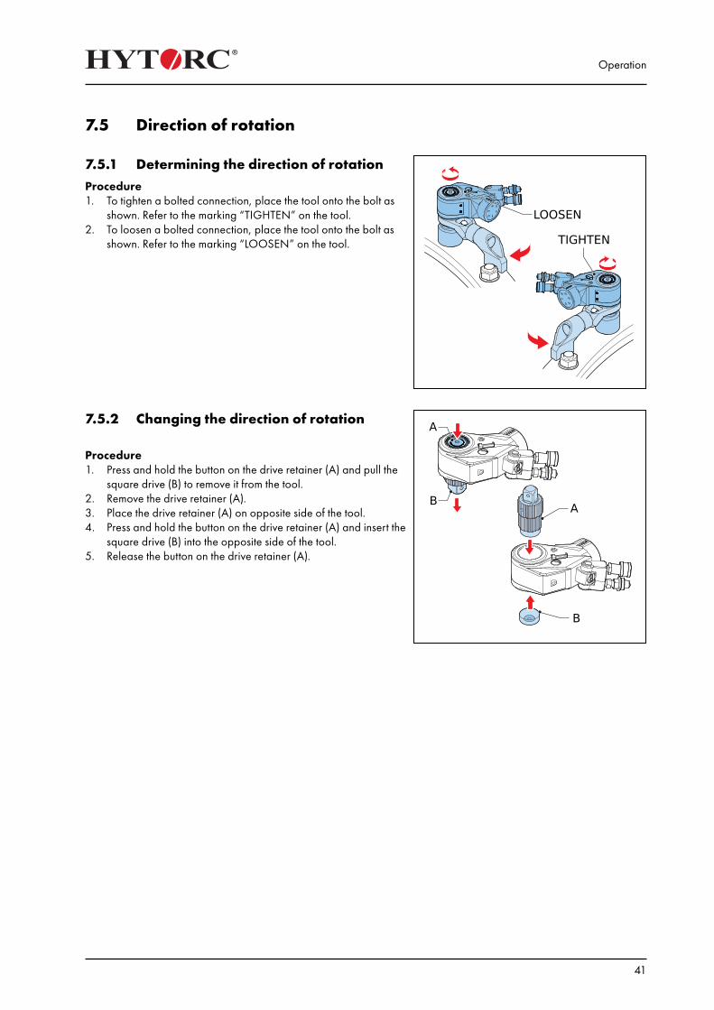
7.5.1 Determining the direction of rotationProcedure1. To tighten a bolted connection, place the tool onto the bolt as
shown. Refer to the marking “TIGHTEN” on the tool.2. To loosen a bolted connection, place the tool onto the bolt as
shown. Refer to the marking “LOOSEN” on the tool.
7.5.2 Changing the direction of rotation
Procedure1. Press and hold the button on the drive retainer (A) and pull the
square drive (B) to remove it from the tool.2. Remove the drive retainer (A).3. Place the drive retainer (A) on opposite side of the tool.4. Press and hold the button on the drive retainer (A) and insert the
square drive (B) into the opposite side of the tool.5. Release the button on the drive retainer (A).
Operation
42
7.6 Tightening and loosening a bolted flange connection
Warning:• When you use a hex socket, do not use more than the specified torque.• Place the tool with the socket on the nut or the bolt. Make sure that the socket is placed over the nut
or the bolt as far as possible. Obey the safety instructions for sockets.• Place the reaction arm against a solid reaction point that can handle the load. Obey the safety
instructions for reaction arms.• Make sure that the tool is free of the reaction point and other obstructions.• Start the system momentarily. If the tool tends to creep or stand askew, stop immediately and adjust
the reaction arm to a more solid and secure position.
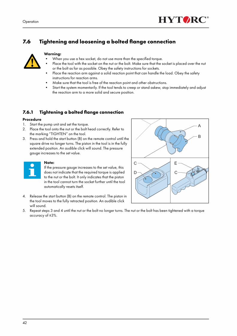
7.6.1 Tightening a bolted flange connectionProcedure1. Start the pump unit and set the torque.2. Place the tool onto the nut or the bolt head correctly. Refer to
the marking “TIGHTEN” on the tool.3. Press and hold the start button (B) on the remote control until the
square drive no longer turns. The piston in the tool is in the fully extended position. An audible click will sound. The pressure gauge increases to the set value.
Note: If the pressure gauge increases to the set value, this does not indicate that the required torque is applied to the nut or the bolt. It only indicates that the piston in the tool cannot turn the socket further until the tool automatically resets itself.
4. Release the start button (B) on the remote control. The piston in the tool moves to the fully retracted position. An audible click will sound.
5. Repeat steps 3 and 4 until the nut or the bolt no longer turns. The nut or the bolt has been tightened with a torque accuracy of ±3%.
Operation
43
7.6.2 Loosening a bolted flange connectionnCaution!• Always set the pressure as low as possible to loosen the nut or the bolt.• If you must constantly use a high pressure to loosen the nut or the bolt, use a heavier HYTORC tool.
Contact your local HYTORC representative for more information.
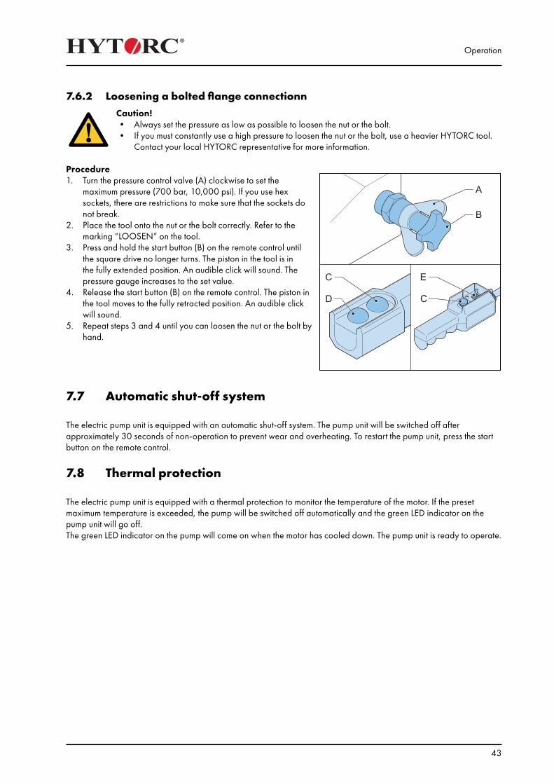
Procedure 1. Turn the pressure control valve (A) clockwise to set the
maximum pressure (700 bar, 10,000 psi). If you use hex sockets, there are restrictions to make sure that the sockets do not break.
2. Place the tool onto the nut or the bolt correctly. Refer to the marking “LOOSEN” on the tool.
3. Press and hold the start button (B) on the remote control until the square drive no longer turns. The piston in the tool is in the fully extended position. An audible click will sound. The pressure gauge increases to the set value.
4. Release the start button (B) on the remote control. The piston in the tool moves to the fully retracted position. An audible click will sound.
5. Repeat steps 3 and 4 until you can loosen the nut or the bolt by hand.
7.7 Automatic shut-off system
The electric pump unit is equipped with an automatic shut-off system. The pump unit will be switched off after approximately 30 seconds of non-operation to prevent wear and overheating. To restart the pump unit, press the start button on the remote control.
7.8 Thermal protection
The electric pump unit is equipped with a thermal protection to monitor the temperature of the motor. If the preset maximum temperature is exceeded, the pump will be switched off automatically and the green LED indicator on the pump unit will go off.The green LED indicator on the pump will come on when the motor has cooled down. The pump unit is ready to operate.

Operation
44
Maintenance & Storage
45
8. Maintenance & Storage
8.1 Preventive maintenance• Replace the hydraulic oil after every 40 hours of operation or at least twice a year. Use only high-grade hydraulic
oil (ISO VG 32 or ISO VG 46 in more extreme conditions).• Replace the filter of the pump unit at least 3 times a year or more often if the pump unit is used daily or in a dirty
environment.• Electric pump unit: Clean or replace worn carbon brushes of the pump unit.• Clean dirty hose couplings. Replace defective hose couplings.• Replace the hydraulic oil when it has a white, milky look.
8.2 Maintenance by HYTORC• Have the tool fully disassembled, cleaned, inspected and lubricated at least once a year.• When the tool is dirty because of sand or another abrasive, have the tool fully disassembled, cleaned, inspected
and lubricated immediately.• Have the pressure gauge calibrated and refilled with glycerin at least once a year.• Have the rotor shaft and the rotor shaft bearings of the pump motor cleaned and lubricated at least once a year.• Have the air hose to the remote control inspected for obstructions or kinks periodically.• Have the spring-loaded buttons on the remote control inspected if they do not operate smoothly.• Have the pressure control valve of the pump unit cleaned at least once a year.
8.3 Storing the cablesProcedure1. Wind the remote control cable around the frame.2. Place the remote control in the remote control clamp.3. Electric pump unit: Wind the power supply cable around the frame.

Maintenance & Storage
46
Troubleshooting
47
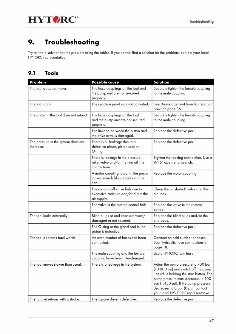
9. TroubleshootingTry to find a solution for the problem using the tables. If you cannot find a solution for the problem, contact your local HYTORC representative.
9.1 Tools
Problem Possible cause Solution
The tool does not move. The hose couplings on the tool and the pump unit are not se-cured properly.
Securely tighten the female coupling to the male coupling.
The tool stalls. The reaction pawl was not activated. See Disengagement lever for reaction pawl on page 36.
The piston in the tool does not retract. The hose couplings on the tool and the pump unit are not secured properly.
Securely tighten the female coupling to the male coupling.
The linkage between the piston and the drive arms is damaged.
Replace the defective part.
The pressure in the system does not increase.
There is oil leakage due to a defective piston, piston seal or O-ring.
Replace the defective part.
There is leakage in the pressure relief valve and/or the two oil line connections.
Tighten the leaking connection. Use a 9/16” open-end wrench.
A motor coupling is worn. The pump makes sounds like pebbles in a tin can.
Replace the motor coupling.
The air shut-off valve fails due to excessive moisture and/or dirt in the air supply.
Clean the air shut-off valve and the air lines.
The valve in the remote control fails. Replace the valve in the remote control.
The tool leaks externally. Blind plugs or end caps are worn/damaged or not secured.
Replace the blind plugs and/or the end caps.
The O-ring or the gland seal in the piston is defective.
Replace the defective part.
The tool operates backwards. An even number of hoses has been connected.
Connect an odd number of hoses. See Hydraulic hose connections on page 18.
The male coupling and the female coupling have been interchanged.
Use a HYTORC twin hose.
The tool moves slower than usual. There is a leakage in the system. Adjust the pump pressure to 700 bar (10,000 psi) and switch off the pump unit while holding the start button. The pump pressure must decrease to 100 bar (1,450 psi). If the pump pressure decreases to 0 bar (0 psi), contact your local HY- TORC representative.
The ratchet returns with a stroke. The square drive is defective. Replace the defective part.
Troubleshooting
48
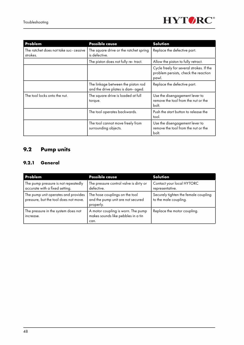
Problem Possible cause Solution
The ratchet does not take suc- cessive strokes.
The square drive or the ratchet spring is defective.
Replace the defective part.
The piston does not fully re- tract. Allow the piston to fully retract.
Cycle freely for several strokes. If the problem persists, check the reaction pawl.
The linkage between the piston rod and the drive plates is dam- aged.
Replace the defective part.
The tool locks onto the nut. The square drive is loaded at full torque.
Use the disengagement lever to remove the tool from the nut or the bolt.
The tool operates backwards. Push the start button to release the tool.
The tool cannot move freely from surrounding objects.
Use the disengagement lever to remove the tool from the nut or the bolt.
9.2 Pump units
9.2.1 General
Problem Possible cause Solution
The pump pressure is not repeatedly accurate with a fixed setting.
The pressure control valve is dirty or defective.
Contact your local HYTORC representative.
The pump unit operates and provides pressure, but the tool does not move.
The hose couplings on the tool and the pump unit are not secured properly.
Securely tighten the female coupling to the male coupling.
The pressure in the system does not increase.
A motor coupling is worn. The pump makes sounds like pebbles in a tin can.
Replace the motor coupling.
Troubleshooting
49
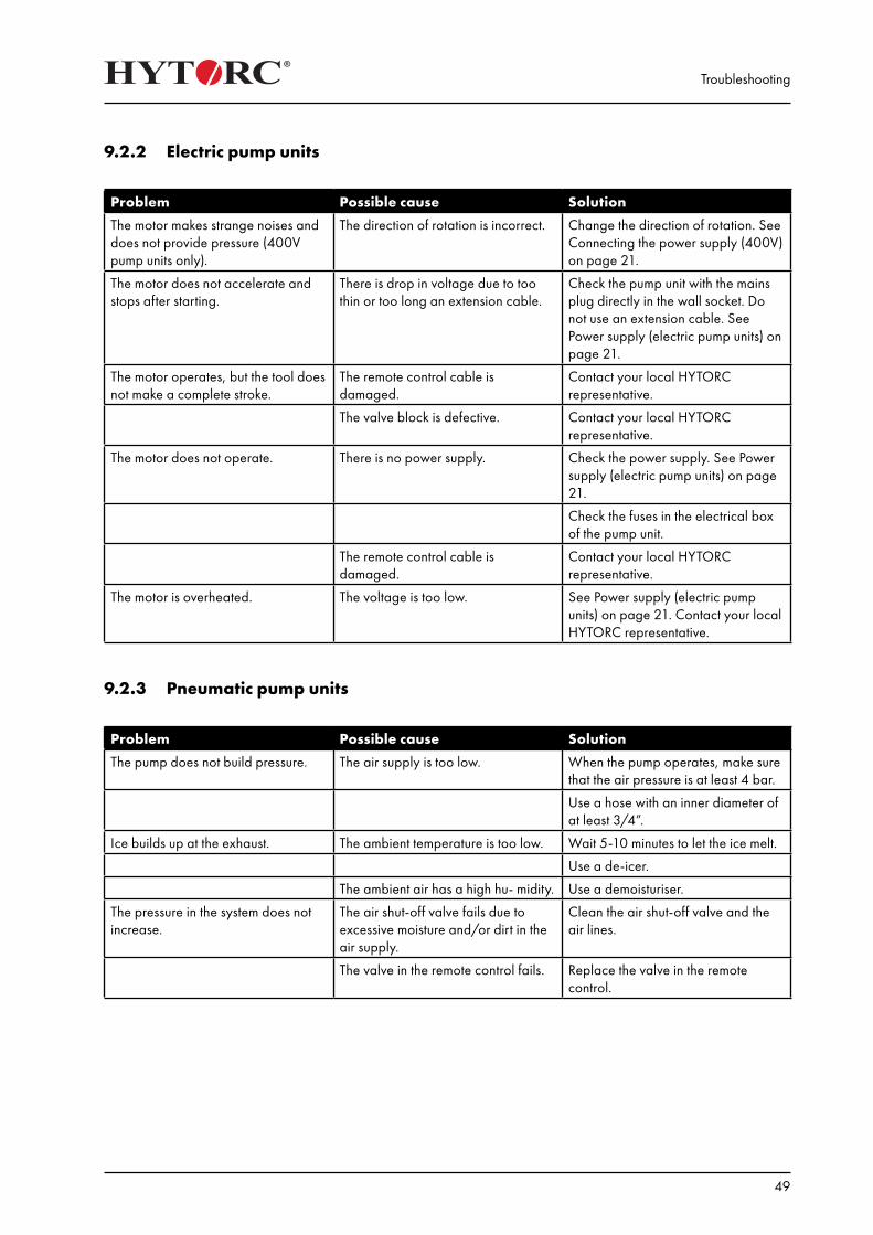
9.2.2 Electric pump units
Problem Possible cause Solution
The motor makes strange noises and does not provide pressure (400V pump units only).
The direction of rotation is incorrect. Change the direction of rotation. See Connecting the power supply (400V) on page 21.
The motor does not accelerate and stops after starting.
There is drop in voltage due to too thin or too long an extension cable.
Check the pump unit with the mains plug directly in the wall socket. Do not use an extension cable. See Power supply (electric pump units) on page 21.
The motor operates, but the tool does not make a complete stroke.
The remote control cable is damaged.
Contact your local HYTORC representative.
The valve block is defective. Contact your local HYTORC representative.
The motor does not operate. There is no power supply. Check the power supply. See Power supply (electric pump units) on page 21.
Check the fuses in the electrical box of the pump unit.
The remote control cable is damaged.
Contact your local HYTORC representative.
The motor is overheated. The voltage is too low. See Power supply (electric pump units) on page 21. Contact your local HYTORC representative.
9.2.3 Pneumatic pump units
Problem Possible cause Solution
The pump does not build pressure. The air supply is too low. When the pump operates, make sure that the air pressure is at least 4 bar.
Use a hose with an inner diameter of at least 3/4”.
Ice builds up at the exhaust. The ambient temperature is too low. Wait 5-10 minutes to let the ice melt.
Use a de-icer.
The ambient air has a high hu- midity. Use a demoisturiser.
The pressure in the system does not increase.
The air shut-off valve fails due to excessive moisture and/or dirt in the air supply.
Clean the air shut-off valve and the air lines.
The valve in the remote control fails. Replace the valve in the remote control.

Troubleshooting
50
Technical data
51
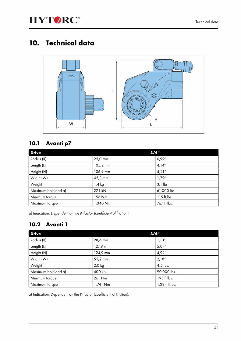
10. Technical data
10.1 Avanti p7
Drive 3/4”
Radius (R) 25,0 mm 0,99”
Length (L) 105,2 mm 4,14”
Height (H) 106,9 mm 4,21”
Width (W) 45,3 mm 1,79”
Weight 1,4 kg 3,1 lbs.
Maximum bolt load a) 271 kN 61.000 lbs.
Minimum torque 156 Nm 115 ft.lbs.
Maximum torque 1.040 Nm 767 ft.lbs.
a) Indication. Dependent on the K-factor (coefficient of friction).
10.2 Avanti 1
Drive 3/4”
Radius (R) 28,6 mm 1,13”
Length (L) 127,9 mm 5,04”
Height (H) 124,9 mm 4,92”
Width (W) 55,2 mm 2,18”
Weight 2,0 kg 4,5 lbs.
Maximum bolt load a) 400 kN 90.000 lbs.
Minimum torque 261 Nm 193 ft.lbs.
Maximum torque 1.741 Nm 1.284 ft.lbs. a) Indication. Dependent on the K-factor (coefficient of friction).

Technical data
52
10.3 Avanti 3
Drive 1”
Radius (R) 38,1 mm 1,50”
Length (L) 165,9 mm 6,53”
Height (H) 160,2 mm 6,31”
Width (W) 73,7 mm 2,90”
Weight 4,3 kg 9,5 lbs.
Maximum bolt load a) 787 kN 177.000 lbs.
Minimum torque 604 Nm 445 ft.lbs.
Maximum torque 4.025 Nm 2.861 ft.lbs.
a) Indication. Dependent on the K-factor (coefficient of friction).
10.4 Avanti 5
Drive 1 1/2”
Radius (R) 47,2 mm 1,86”
Length (L) 199,5 mm 7,85”
Height (H) 188,2 mm 7,41”
Width (W) 85,9 mm 3,38”
Weight 7,1 kg 15,6 lbs.
Maximum bolt load a) 1.027 kN 231.000 lbs.
Minimum torque 1.090 Nm 804 ft.lbs.
Maximum torque 7.267 Nm 5.360 ft.lbs.
a) Indication. Dependent on the K-factor (coefficient of friction).
10.5 Avanti 8
Drive 1 1/2”
Radius (R) 52,5 mm 2,07”
Length (L) 224,2 mm 8,83”
Height (H) 212,7 mm 8,38”
Width (W) 98,0 mm 3,86”
Weight 9,4 kg 20,8 lbs.
Maximum bolt load a) 1.450 kN 326.000 lbs.
Minimum torque 1.578 Nm 1.164 ft.lbs.
Maximum torque 10.521 Nm 7.760 ft.lbs.
a) Indication. Dependent on the K-factor (coefficient of friction).
Technical data
53
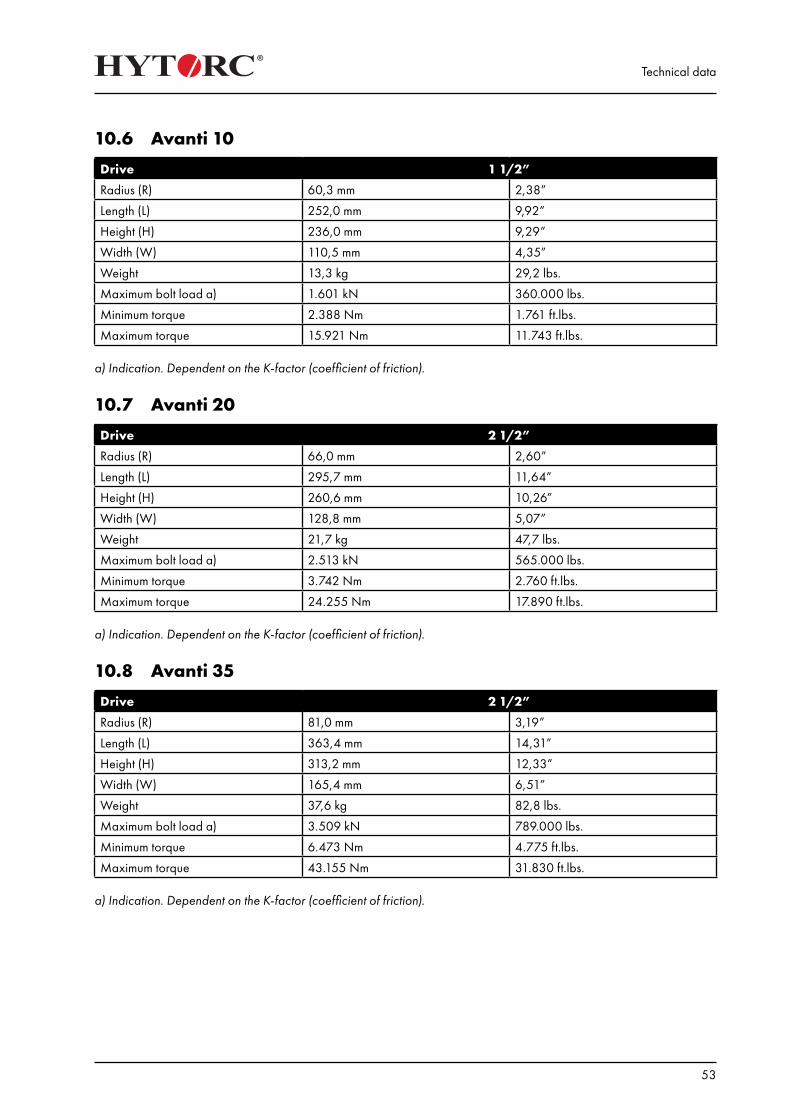
10.6 Avanti 10
Drive 1 1/2”
Radius (R) 60,3 mm 2,38”
Length (L) 252,0 mm 9,92”
Height (H) 236,0 mm 9,29”
Width (W) 110,5 mm 4,35”
Weight 13,3 kg 29,2 lbs.
Maximum bolt load a) 1.601 kN 360.000 lbs.
Minimum torque 2.388 Nm 1.761 ft.lbs.
Maximum torque 15.921 Nm 11.743 ft.lbs.
a) Indication. Dependent on the K-factor (coefficient of friction).
10.7 Avanti 20
Drive 2 1/2”
Radius (R) 66,0 mm 2,60”
Length (L) 295,7 mm 11,64”
Height (H) 260,6 mm 10,26”
Width (W) 128,8 mm 5,07”
Weight 21,7 kg 47,7 lbs.
Maximum bolt load a) 2.513 kN 565.000 lbs.
Minimum torque 3.742 Nm 2.760 ft.lbs.
Maximum torque 24.255 Nm 17.890 ft.lbs.
a) Indication. Dependent on the K-factor (coefficient of friction).
10.8 Avanti 35
Drive 2 1/2”
Radius (R) 81,0 mm 3,19”
Length (L) 363,4 mm 14,31”
Height (H) 313,2 mm 12,33”
Width (W) 165,4 mm 6,51”
Weight 37,6 kg 82,8 lbs.
Maximum bolt load a) 3.509 kN 789.000 lbs.
Minimum torque 6.473 Nm 4.775 ft.lbs.
Maximum torque 43.155 Nm 31.830 ft.lbs.
a) Indication. Dependent on the K-factor (coefficient of friction).
Technical data
54
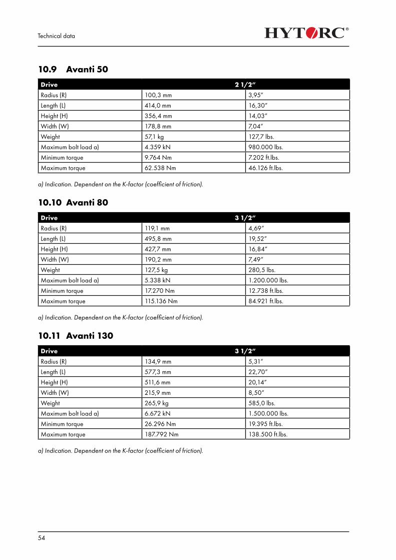
10.9 Avanti 50
Drive 2 1/2”
Radius (R) 100,3 mm 3,95”
Length (L) 414,0 mm 16,30”
Height (H) 356,4 mm 14,03”
Width (W) 178,8 mm 7,04”
Weight 57,1 kg 127,7 lbs.
Maximum bolt load a) 4.359 kN 980.000 lbs.
Minimum torque 9.764 Nm 7.202 ft.lbs.
Maximum torque 62.538 Nm 46.126 ft.lbs.
a) Indication. Dependent on the K-factor (coefficient of friction).
10.10 Avanti 80
Drive 3 1/2”
Radius (R) 119,1 mm 4,69”
Length (L) 495,8 mm 19,52”
Height (H) 427,7 mm 16,84”
Width (W) 190,2 mm 7,49”
Weight 127,5 kg 280,5 lbs.
Maximum bolt load a) 5.338 kN 1.200.000 lbs.
Minimum torque 17.270 Nm 12.738 ft.lbs.
Maximum torque 115.136 Nm 84.921 ft.lbs.
a) Indication. Dependent on the K-factor (coefficient of friction).
10.11 Avanti 130
Drive 3 1/2”
Radius (R) 134,9 mm 5,31”
Length (L) 577,3 mm 22,70”
Height (H) 511,6 mm 20,14”
Width (W) 215,9 mm 8,50”
Weight 265,9 kg 585,0 lbs.
Maximum bolt load a) 6.672 kN 1.500.000 lbs.
Minimum torque 26.296 Nm 19.395 ft.lbs.
Maximum torque 187.792 Nm 138.500 ft.lbs.
a) Indication. Dependent on the K-factor (coefficient of friction).
Technical data
55
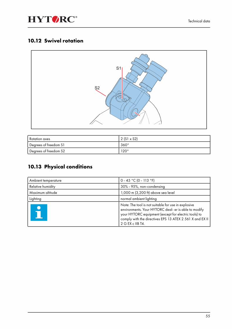
10.12 Swivel rotation
Rotation axes 2 (S1 x S2)
Degrees of freedom S1 360°
Degrees of freedom S2 120°
10.13 Physical conditions
Ambient temperature 0 - 45 °C (0 - 113 °F)
Relative humidity 30% - 95%, non-condensing
Maximum altitude 1,000 m (3,200 ft) above sea level
Lighting normal ambient lighting
Note: The tool is not suitable for use in explosive environments. Your HYTORC deal- er is able to modify your HYTORC equipment (except for electric tools) to comply with the directives EPS 13 ATEX 2 561 X and EX II 2 G EX c IIB T4.
Technical data
56
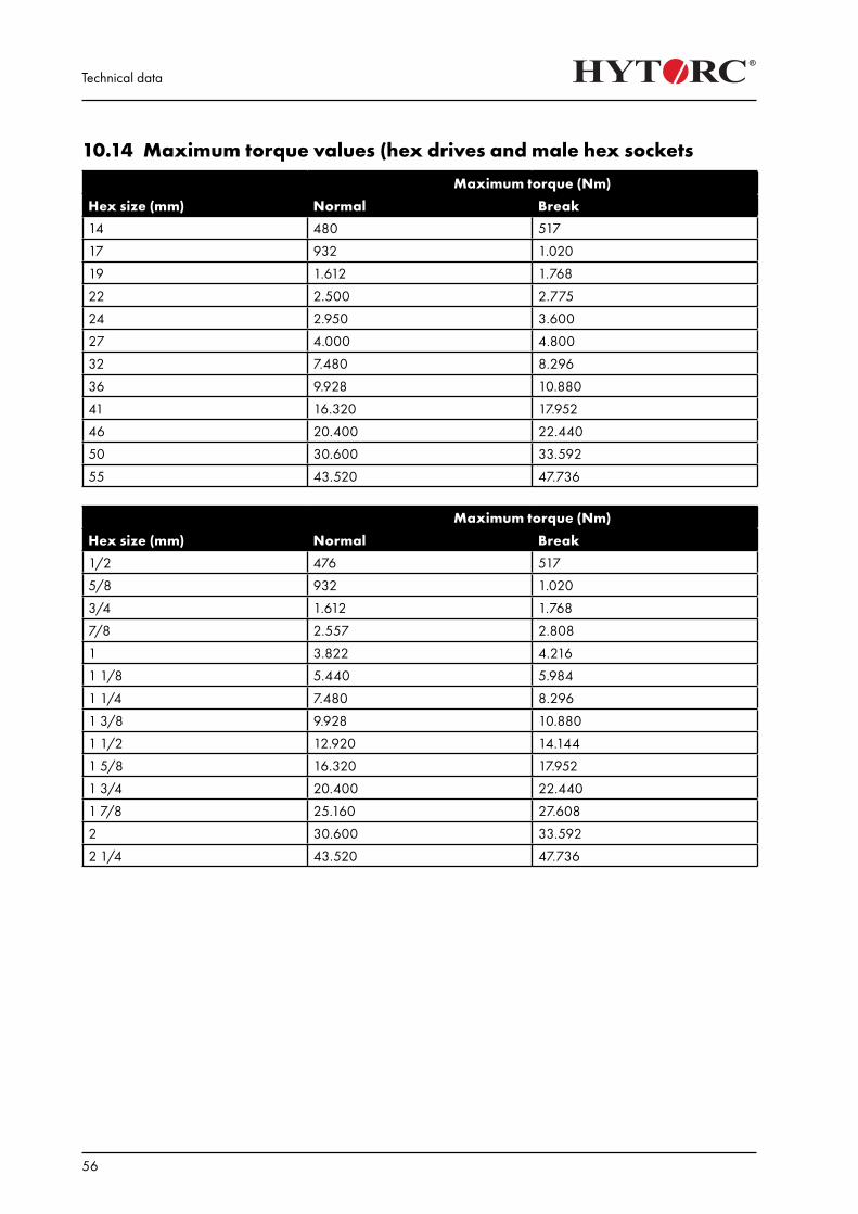
10.14 Maximum torque values (hex drives and male hex sockets
Maximum torque (Nm)
Hex size (mm) Normal Break
14 480 517
17 932 1.020
19 1.612 1.768
22 2.500 2.775
24 2.950 3.600
27 4.000 4.800
32 7.480 8.296
36 9.928 10.880
41 16.320 17.952
46 20.400 22.440
50 30.600 33.592
55 43.520 47.736
Maximum torque (Nm)
Hex size (mm) Normal Break
1/2 476 517
5/8 932 1.020
3/4 1.612 1.768
7/8 2.557 2.808
1 3.822 4.216
1 1/8 5.440 5.984
1 1/4 7.480 8.296
1 3/8 9.928 10.880
1 1/2 12.920 14.144
1 5/8 16.320 17.952
1 3/4 20.400 22.440
1 7/8 25.160 27.608
2 30.600 33.592
2 1/4 43.520 47.736
Technical data
57
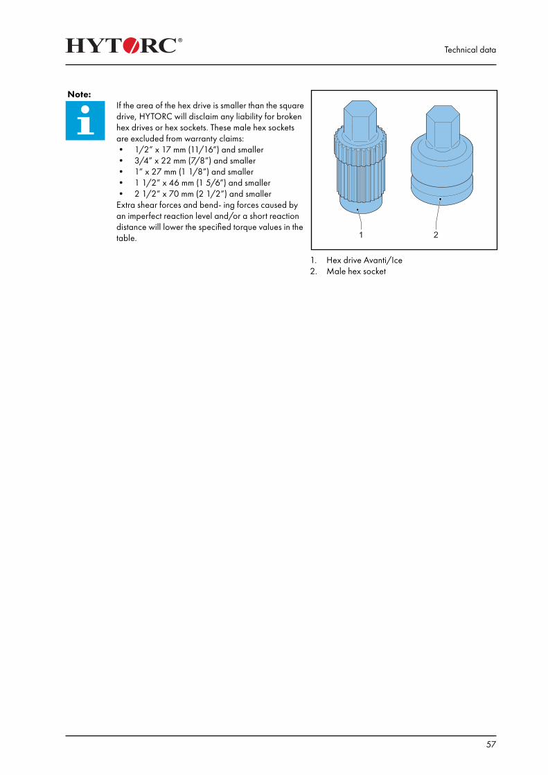
Note: If the area of the hex drive is smaller than the square drive, HYTORC will disclaim any liability for broken hex drives or hex sockets. These male hex sockets are excluded from warranty claims:• 1/2” x 17 mm (11/16”) and smaller• 3/4” x 22 mm (7/8”) and smaller• 1” x 27 mm (1 1/8”) and smaller• 1 1/2” x 46 mm (1 5/6”) and smaller• 2 1/2” x 70 mm (2 1/2”) and smallerExtra shear forces and bend- ing forces caused by an imperfect reaction level and/or a short reaction distance will lower the specified torque values in the table.
1. Hex drive Avanti/Ice2. Male hex socket

Technical data
58
Declaration of Conformity
59
Declaration of Conformity
(according to Annex II.1.A of the Machinery Directive)
We,
HYTORC BV Platinawerf 8, 6641 TL Beuningen Nederland
declare under our own responsibility:We are the manufacturer of the Avanti hydraulic socket wrench with optional accessories.
The Avanti hydraulic socket wrench with optional accessories is in conformity with the provisions of the following directives:• 2006/42/EC (Machine Directive)• 98/23/EC (Pressure Equipment Directive)
The following harmonized standards have been applied:• NEN-EN 349• NEN-EN 1005-2• NEN-EN 1005-3• NEN-EN 1005-4• NEN-EN 4413• NEN-EN-ISO 12100• NEN-EN-ISO 13857
Plaats: Beuningen (The Netherlands)Datum: January 05, 2016Naam: HYTORC
CEO: M. van Kortenhof
11. Declaration of Conformity