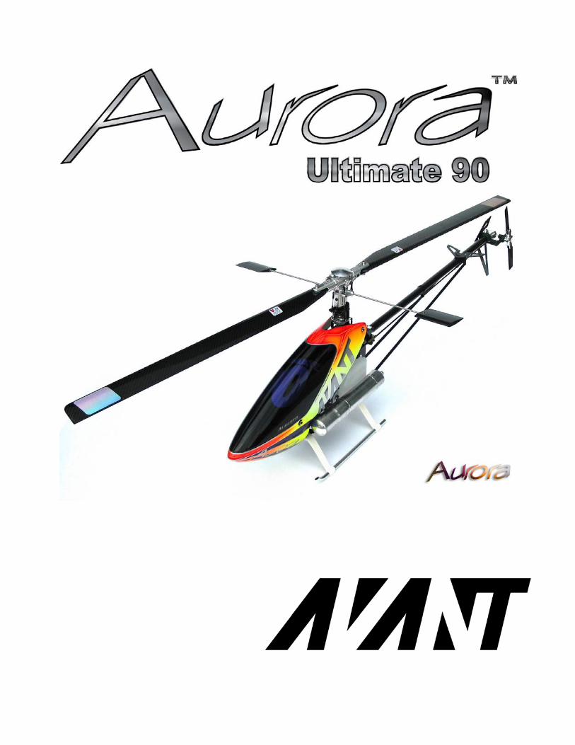
AVANT A - IRCHA Library/Avant Aurora.pdf · AVANT Aurora Ultimate 90 Assembly Manual _5....
47
Transcript of AVANT A - IRCHA Library/Avant Aurora.pdf · AVANT Aurora Ultimate 90 Assembly Manual _5....
2 AVANT Aurora Ultimate 90 Assembly Manual
AVANT Aurora Ultimate 90 Assembly Manual V1.08
LIABILITY DISCLAIMER This kit is for a radio controlled (RC) helicopter. RC Helicopters are not toys. Moving parts can present a hazard to operators, bystanders and anyone or anything that could be reached by the RC helicopter. Improper operation, maintenance or assembly can potentially cause a helicopter to pose a danger to persons or objects including but not limited to the possibility of causing serious physical injury and even death. This product is intended to be used by experienced adult radio control helicopter pilots under controlled safety conditions and on locations properly authorized and setup for safe flying and away from other people. Under no circumstance should a minor be allowed to operate this or any radio controlled helicopter without the approval, supervision and direction of his parent or legal guardian who takes full responsibility for the minor's actions. Do not operate an RC helicopter within the vicinity of homes, trees, electrical lines during inclement weather or rain or near crowds of people. After leaving its facilities the manufacturer has no way of maintaining control or supervision over the assembly and/or operation of the helicopter. The manufacturer and/or its agents assume no responsibility or liability whatsoever for any damages including but not limited to ones generated by incidental or consequential damages. The operator of the helicopter assumes all responsibility and liability that could be result from the correct or incorrect operation of the helicopter. Symbols:
Important, Correct, Incorrect, Danger, Allow it to set for some time before continuing
Note: Unless indicated otherwise all screws, balls and threads are installed with Blue Loctite
AVANT Aurora Ultimate 90 Assembly Manual _3
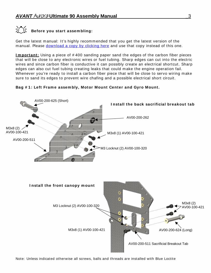
Before you start assembling: Get the latest manual: It’s highly recommended that you get the latest version of the manual. Please download a copy by clicking here and use that copy instead of this one. Important: Using a piece of #400 sanding paper sand the edges of the carbon fiber pieces that will be close to any electronic wires or fuel tubing. Sharp edges can cut into the electric wires and since carbon fiber is conductive it can possibly create an electrical shortcut. Sharp edges can also cut fuel tubing creating leaks that could make the engine operation fail. Whenever you’re ready to install a carbon fiber piece that will be close to servo wiring make sure to sand its edges to prevent wire chafing and a possible electrical short circuit. Bag #1: Left Frame assembly, Motor Mount Center and Gyro Mount. A
V00-200-625 (Short)
M3x8 (1) AV00-100-421
M3 Locknut (2) AV00-100-320
M3 Locknut (2) AV00-100-320
AV00-200-624 (Long)
M3x8 (2) AV00-100-421
Install the back sacrificial breakout tab
AV00-200-262
M3x8 (2) AV00-100-421
AV00-200-511
Install the front canopy mount
M3x8 (1) AV00-100-421
AV00-200-511 Sacrificial Breakout Tab
Note: Unless indicated otherwise all screws, balls and threads are installed with Blue Loctite
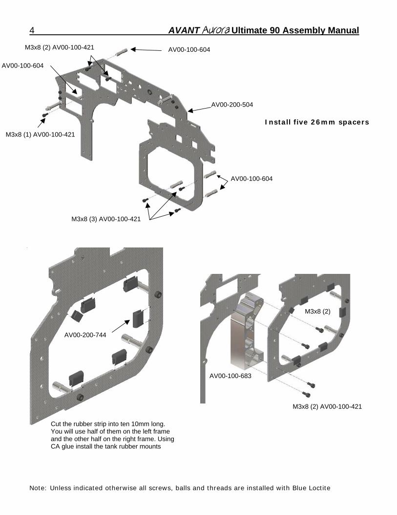
4 AVANT Aurora Ultimate 90 Assembly Manual
M3x8 (2) AV00-100-421 AV00-100-604
AV00-100-604
AV00-200-504
Install five 26mm spacers
M3x8 (1) AV00-100-421 AV00-100-604
M3x8 (3) AV00-100-421
stubs and two 5mm long grommets
M3x8 (2)
AV00-200-744
AV00-100-683
M3x8 (2) AV00-100-421
Cut the rubber strip into ten 10mm long. You will use half of them on the left frame and the other half on the right frame. Using CA glue install the tank rubber mounts
Note: Unless indicated otherwise all screws, balls and threads are installed with Blue Loctite
AVANT Aurora Ultimate 90 Assembly Manual _5
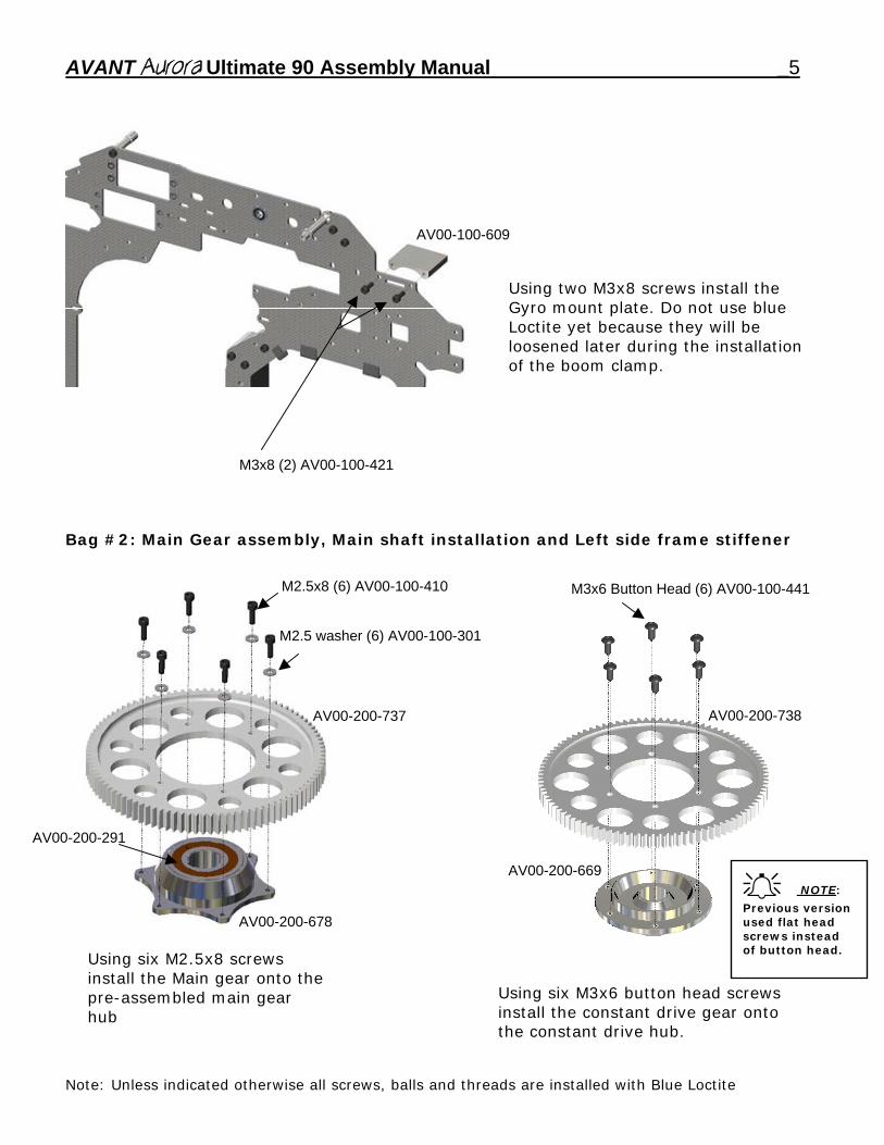
AV00-100-609
Using two M3x8 screws install the Gyro mount plate. Do not use blue Loctite yet because they will be loosened later during the installation of the boom clamp.
M3x8 (2) AV00-100-421 Bag #2: Main Gear assembly, Main shaft installation and Left side frame stiffener
M2.5x8 (6) AV00-100-410 M3x6 Button Head (6) AV00-100-441
M2.5 washer (6) AV00-100-301
AV00-200-738 AV00-200-737
AV00-200-291
AV00-200-669 NOTE:
Previous version used flat head screws instead of button head.
AV00-200-678
Using six M2.5x8 screws install the Main gear onto the pre-assembled main gear hub
Using six M3x6 button head screws install the constant drive gear onto the constant drive hub.
Note: Unless indicated otherwise all screws, balls and threads are installed with Blue Loctite
6 AVANT Aurora Ultimate 90 Assembly Manual
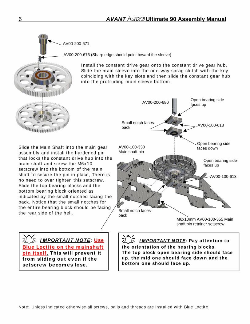
Install the constant drive gear onto the constant drive gear hub. Slide the main sleeve into the one-way sprag clutch with the key coinciding with the key slots and then slide the constant gear hub into the protruding main sleeve bottom.
Slide the Main Shaft into the main gear assembly and install the hardened pin that locks the constant drive hub into the main shaft and screw the M6x10 setscrew into the bottom of the main shaft to secure the pin in place, There is no need to over tighten this setscrew. Slide the top bearing blocks and the bottom bearing block oriented as indicated by the small notched facing the back. Notice that the small notches for the entire bearing block should be facing the rear side of the heli.
AV00-200-676 (Sharp edge should point toward the sleeve)
AV00-200-671
AV00-200-680
AV00-100-613
Open bearing side faces up
Open bearing side faces down
Open bearing side faces up
Small notch faces back
M6x10mm AV00-100-355 Main shaft pin retainer setscrew
Small notch faces back AV00-100-613
AV00-100-333 Main shaft pin
IMPORTANT NOTE: Use Blue Loctite on the mainshaft pin itself. This will prevent it from sliding out even if the setscrew becomes lose.
IMPORTANT NOTE: Pay attention to the orientation of the bearing blocks. The top block open bearing side should face up, the mid one should face down and the bottom one should face up.
Note: Unless indicated otherwise all screws, balls and threads are installed with Blue Loctite
AVANT Aurora Ultimate 90 Assembly Manual _7
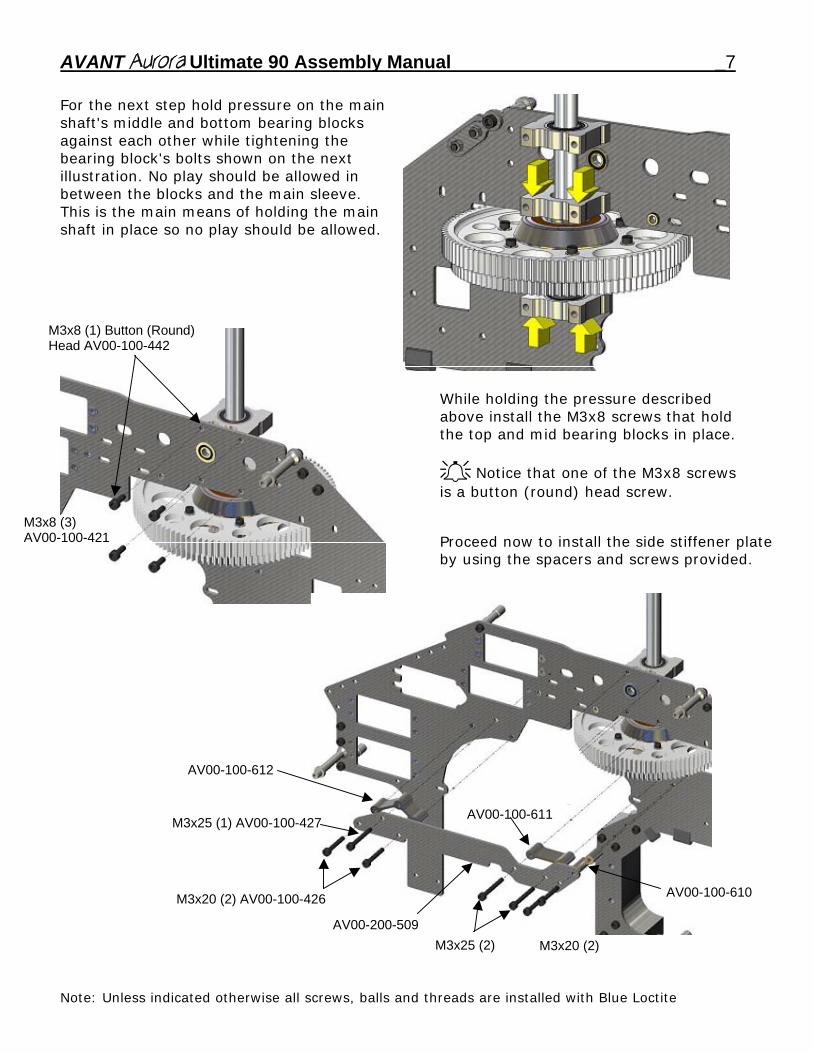
For the next step hold pressure on the main shaft's middle and bottom bearing blocks against each other while tightening the bearing block's bolts shown on the next illustration. No play should be allowed in between the blocks and the main sleeve. This is the main means of holding the main shaft in place so no play should be allowed.
While holding the pressure described above install the M3x8 screws that hold the top and mid bearing blocks in place.
Notice that one of the M3x8 screws is a button (round) head screw.
Proceed now to install the side stiffener plate by using the spacers and screws provided.
M3x8 (1) Button (Round) Head AV00-100-442
M3x8 (3) AV00-100-421
AV00-100-610
AV00-100-611
AV00-100-612
M3x20 (2) AV00-100-426
AV00-200-509
M3x25 (1) AV00-100-427
M3x25 (2) M3x20 (2)
Note: Unless indicated otherwise all screws, balls and threads are installed with Blue Loctite
8 AVANT Aurora Ultimate 90 Assembly Manual
Note: Unless indicated otherwise all screws, balls and threads are installed with Blue Loctite
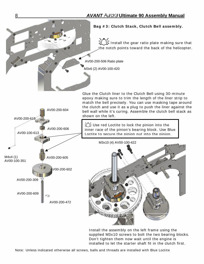
Bag #3: Clutch Stack, Clutch Bell assembly.
M3x6 (2) AV00-100-420
AV00-200-506 Ratio plate
Install the gear ratio plate making sure that the notch points toward the back of the helicopter.
AV00-200-472
M4x4 (1) AV00-100-351
AV00-200-602
AV00-200-609
AV00-200-309
AV00-200-605
AV00-100-613
AV00-200-604
AV00-200-606
M3x10 (4) AV00-100-422
Glue the Clutch liner to the Clutch Bell using 30-minute epoxy making sure to trim the length of the liner strip to match the bell precisely. You can use masking tape around the clutch and use it as a plug to push the liner against the bell wall while it’s curing. Assemble the clutch bell stack as shown on the left.
Use red Loctite to lock the pinion into the inner race of the pinion’s bearing block. Use Blue Loctite to secure the pinion nut into the pinion.
AV00-200-619
Install the assembly on the left frame using the supplied M3x10 screws to bolt the two bearing blocks. Don’t tighten them now wait until the engine is installed to let the starter shaft fit in the clutch first.
AVANT Aurora Ultimate 90 Assembly Manual _9
Bag #4: Tail Pickup gear mechanism and gear meshing method.
6mm Shim
AV00-100-331
AV00-200-721
AV00-200-618
AV00-200-619 Assemble the vertical pickup shaft as shown on the left. The roll pin (black one) is the one above and the dowel pin (silver one) is the one at the bottom side.
Assemble the torque input shaft assembly as shown. The spacing between the blocks is set by the holes in the frames.
6mm Shim
AV00-200-619 (2)
M3x4 (1) AV00-100-350
AV00-200-726AV00-100-330
Install the two assemblies into the frame as shown. Don't tighten the collar or the 2.5mm dog-bone pin and setscrew until they are placed in the frames and the mesh is checked for no play at all and flush alignment of the inner face of the teeth on both gears.
You need to replace the 6mm id bearing spacers until there is no play between the bevel gears. Follow the instructions shown in the next pages for the gear mesh.
M3x8 (8) AV00-100-421
AV00-100-332
M3x4 (1) AV00-100-350
M3x4 (1)
AV00-200-608
AV00-200-307 - 6mm ID x 0.1mm Shim AV00-200-308 - 6mm ID x 0.2mm Shim AV00-200-309 - 6mm ID x 0.3mm Shim
Note: Unless indicated otherwise all screws, balls and threads are installed with Blue Loctite
10 AVANT Aurora Ultimate 90 Assembly Manual
VERY IMPORTANT!!! READ AND FOLLOW THE TAIL GEAR MESH METHOD
Failure to do so can cause the tail gears to fail in flight This is the method used to do a correct mesh on the Aurora tail gears. This applies to both the front set (the set inside the frames) and the back set (the set inside the tailcase). The Aurora has a large window to inspect the gears inside the frames as well as the ones inside the tailcase.
Frame inspection window. Tailcase inspection window.
There are three things that need to be assured for a correct mesh in the Aurora: Flush alignment, No Play and Lubrication.
1) Flush alignment: Make sure that the gears are aligned so that the inner side of the teeth are in the same plane flush to each other at the point of contact. 2) No Play: Make sure there is no play between the gears. 3) Lubrication: Make sure to lubricate the gears with a few drops of fuel before each flying day letting the alcohol evaporate leaving the fuel's oil as lubricant. 1) Flush Alignment: In order to illustrate how to achieve it here's a couple of pictures of gears aligned incorrectly followed by a couple of pictures of correctly aligned ones.
Note: Unless indicated otherwise all screws, balls and threads are installed with Blue Loctite
AVANT Aurora Ultimate 90 Assembly Manual _11
Note: Unless indicated otherwise all screws, balls and threads are installed with Blue Loctite
Wrong alignment case #1: Top gear too forward
Wrong alignment case #2: Bottom gear too forward
12 AVANT Aurora Ultimate 90 Assembly Manual
Correct tooth face alignment:
Note: Unless indicated otherwise all screws, balls and threads are installed with Blue Loctite
Flush alignment is easily achieved because the kit brings four sets of three bearings spacing washers of 0.1, 0.2 and 0.3mm thickness. Combining them you can get from 0.1mm to 0.6mm spacing (0.1), (0.2), (0.1+0.2), (0.3), (0.3+0.1), (0.3+0.2), (0.3+0.2+0.1). In order to align them flush you simplyselect thinner washer shims for the one that's too forward or thicker for the one that's not forward enough.
AVANT Aurora Ultimate 90 Assembly Manual _13
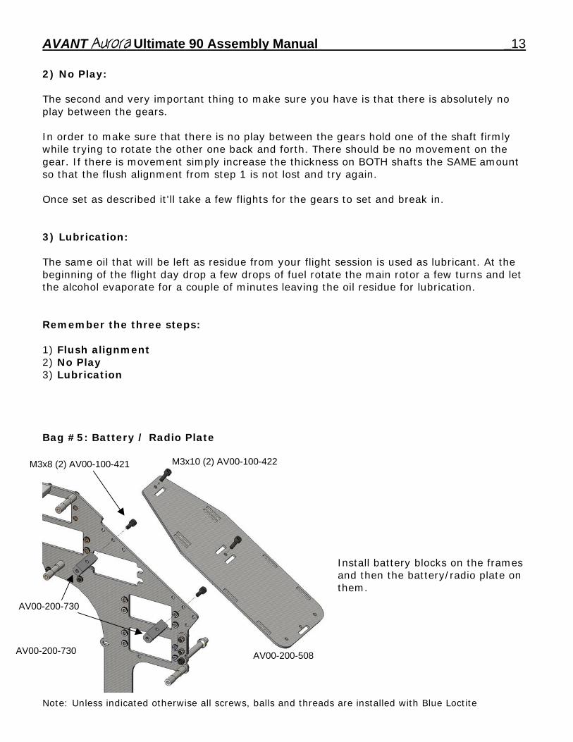
2) No Play: The second and very important thing to make sure you have is that there is absolutely no play between the gears. In order to make sure that there is no play between the gears hold one of the shaft firmly while trying to rotate the other one back and forth. There should be no movement on the gear. If there is movement simply increase the thickness on BOTH shafts the SAME amount so that the flush alignment from step 1 is not lost and try again. Once set as described it'll take a few flights for the gears to set and break in. 3) Lubrication: The same oil that will be left as residue from your flight session is used as lubricant. At the beginning of the flight day drop a few drops of fuel rotate the main rotor a few turns and let the alcohol evaporate for a couple of minutes leaving the oil residue for lubrication. Remember the three steps: 1) Flush alignment 2) No Play 3) Lubrication Bag #5: Battery / Radio Plate
AV00-200-730
AV00-200-730 AV00-200-508
M3x10 (2) AV00-100-422 M3x8 (2) AV00-100-421 Install battery blocks on the frames and then the battery/radio plate on them.
Note: Unless indicated otherwise all screws, balls and threads are installed with Blue Loctite
14 AVANT Aurora Ultimate 90 Assembly Manual
M3x8 (1)
M3x8 (1) AV00-100-421
M3 Locknut (2)
M3x8 (2)
AV00-200-624 (Long)
M3x6 (2) AV00-100-420
AV00-200-506
AV00-200-505
AV00-200-625 (Short)
M3x8 (2) AV00-100-421
AV00-200-511
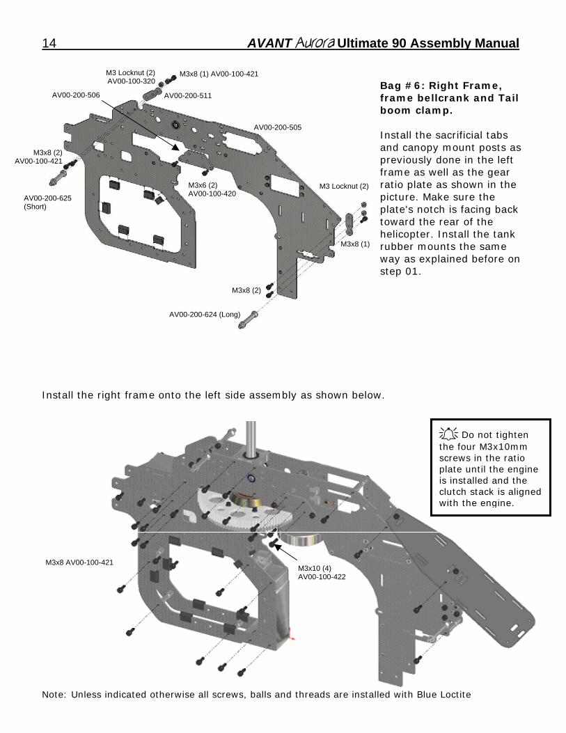
M3 Locknut (2)AV00-100-320 Bag #6: Right Frame,
frame bellcrank and Tail boom clamp. Install the sacrificial tabs and canopy mount posts as previously done in the left frame as well as the gear ratio plate as shown in the picture. Make sure the plate's notch is facing back toward the rear of the helicopter. Install the tank rubber mounts the same way as explained before on step 01.
Install the right frame onto the left side assembly as shown below.
Do not tighten the four M3x10mm screws in the ratio plate until the engine is installed and the clutch stack is aligned with the engine.
M3x8 AV00-100-421 M3x10 (4) AV00-100-422
Note: Unless indicated otherwise all screws, balls and threads are installed with Blue Loctite
AVANT Aurora Ultimate 90 Assembly Manual _15
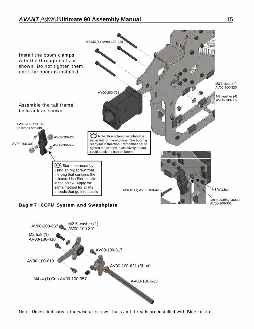
M3x35 (4) AV00-100-428 Install the boom clamps with the through bolts as shown. Do not tighten them until the boom is installed.
M3 locknut (4)
AV00-100-320 AV00-200-753 M3 washer (4)
AV00-100-302 Assemble the tail frame bellcrank as shown.
AV00-200-723 Tail Bellcrank straight
Note: Boomclamp installation is
better left for the end when the boom is ready for installation. Remember not to tighten the clamps excessively or you
AV00-200-260
AV00-200-302
AV00-200-667
could crack the carbon boom.
Bag #7: CCPM System and Swashplate
Start the thread by using an M2 screw from the bag that contains the tailcase. Use Blue Loctite in the screw. Apply the same method for all M2 threads that go into plastic M3 Washer
AV00-100-619
M2.5x8 (1) AV00-100-410
M2.5 washer (1) AV00-100-301
AV00-100-617
AV00-100-621 (Short)
AV00-200-667
M4x4 (1) Cup AV00-100-357 AV00-100-635
M3x18 (1) AV00-100-425
1mm bearing spacer AV00-200-301
Note: Unless indicated otherwise all screws, balls and threads are installed with Blue Loctite
16 AVANT Aurora Ultimate 90 Assembly Manual
M4x4 (1) Cup point Setscrew AV00-100-357
AV00-100-618 AV00-200-667
AV00-100-619
AV00-100-622 (Long)
M4x4 (1) Cup point Setscrew AV00-100-357
AV00-100-620
AV00-100-624
AV00-200-620
AV00-200-668 (7)
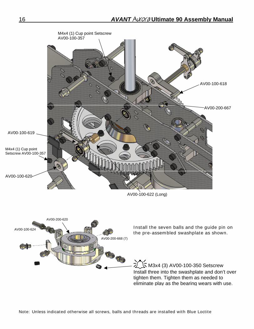
Install the seven balls and the guide pin on the pre-assembled swashplate as shown.
M3x4 (3) AV00-100-350 Setscrew Install three into the swashplate and don’t over tighten them. Tighten them as needed to eliminate play as the bearing wears with use.
Note: Unless indicated otherwise all screws, balls and threads are installed with Blue Loctite
AVANT Aurora Ultimate 90 Assembly Manual _17
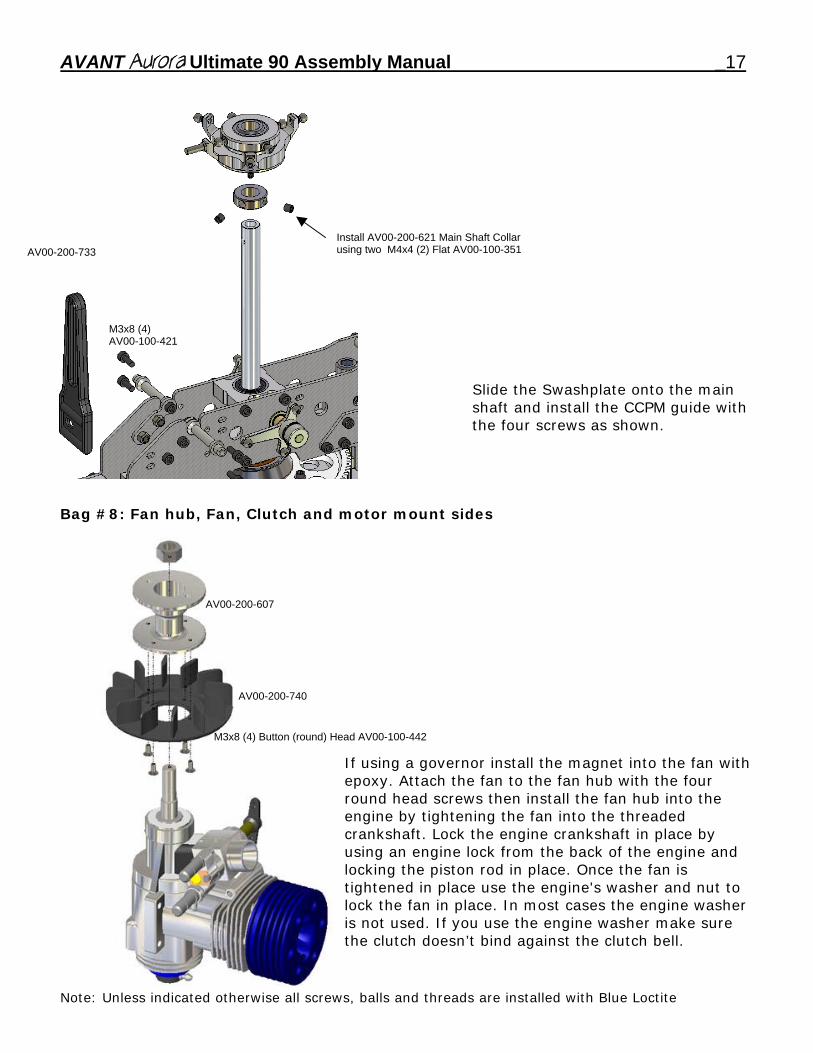
Slide the Swashplate onto the main shaft and install the CCPM guide with the four screws as shown.
M3x8 (4) AV00-100-421
AV00-200-733 Install AV00-200-621 Main Shaft Collar using two M4x4 (2) Flat AV00-100-351
Bag #8: Fan hub, Fan, Clutch and motor mount sides
AV00-200-607
AV00-200-740
M3x8 (4) Button (round) Head AV00-100-442
If using a governor install the magnet into the fan with epoxy. Attach the fan to the fan hub with the four round head screws then install the fan hub into the engine by tightening the fan into the threaded crankshaft. Lock the engine crankshaft in place by using an engine lock from the back of the engine and locking the piston rod in place. Once the fan is tightened in place use the engine's washer and nut to lock the fan in place. In most cases the engine washer is not used. If you use the engine washer make sure the clutch doesn’t bind against the clutch bell.
Note: Unless indicated otherwise all screws, balls and threads are installed with Blue Loctite
18 AVANT Aurora Ultimate 90 Assembly Manual
o
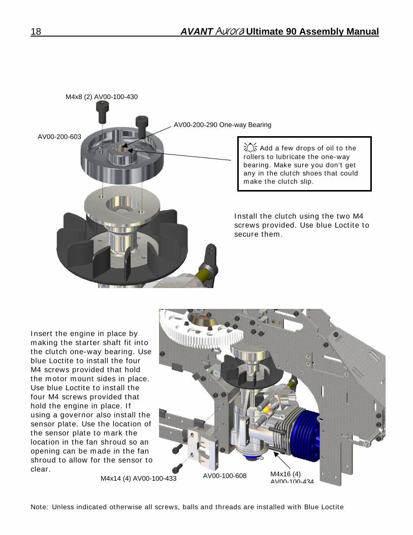
Install the clutch using the two M4 screws provided. Use blue Loctite to secure them.
Insert the engine in place by making the starter shaft fit into the clutch one-way bearing. Use blue Loctite to install the four M4 screws provided that hold the motor mount sides in place. Use blue Loctite to install the four M4 screws provided that hold the engine in place. If using a governor also install the sensor plate. Use the location of the sensor plate to mark the location in the fan shroud so an opening can be made in the fan shroud to allow for the sensor tclear.
AV00-200-603
AV00-200-290 One-way Bearing
M4x14 (4) AV00-100-433 AV00-100-608 M4x16 (4) AV00-100-434
Add a few drops of oil to the rollers to lubricate the one-way bearing. Make sure you don’t get any in the clutch shoes that could make the clutch slip.
M4x8 (2) AV00-100-430
Note: Unless indicated otherwise all screws, balls and threads are installed with Blue Loctite
AVANT Aurora Ultimate 90 Assembly Manual _19
Bag #9: Fan shroud installation
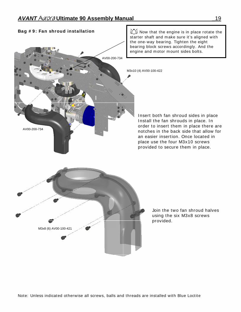
Insert both fan shroud sides in place Install the fan shrouds in place. In order to insert them in place there are notches in the back side that allow for an easier insertion. Once located in place use the four M3x10 screws provided to secure them in place.
AV00-200-734
M3x10 (4) AV00-100-422
AV00-200-734
Now that the engine is in place rotate the starter shaft and make sure it’s aligned with the one-way bearing. Tighten the eight bearing block screws accordingly. And the engine and motor mount sides bolts.
M3x8 (6) AV00-100-421
Join the two fan shroud halves using the six M3x8 screws provided.
Note: Unless indicated otherwise all screws, balls and threads are installed with Blue Loctite
20 AVANT Aurora Ultimate 90 Assembly Manual
sing the provided hardware
o to
Bag #10: Landing gear installation
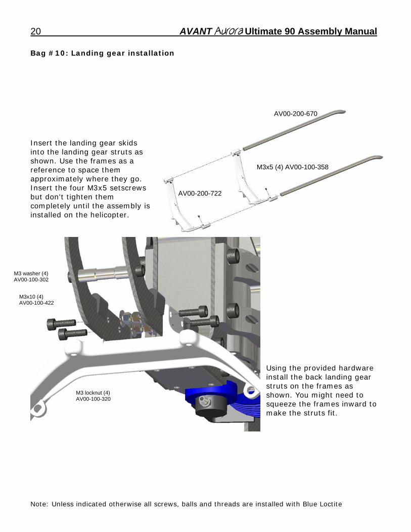
AV00-200-670 Insert the landing gear skids into the landing gear struts as shown. Use the frames as a reference to space them approximately where they go. Insert the four M3x5 setscrews but don't tighten them completely until the assembly is installed on the helicopter.
M3x5 (4) AV00-100-358
AV00-200-722
M3 wa
M3x10 (4)
AV00-100-422
sher (4) AV00-100-302
M3 locknut (4)
Uinstall the back landing gear struts on the frames as shown. You might need tsqueeze the frames inward make the struts fit.
AV00-100-320
Note: Unless indicated otherwise all screws, balls and threads are installed with Blue Loctite
AVANT Aurora Ultimate 90 Assembly Manual _21
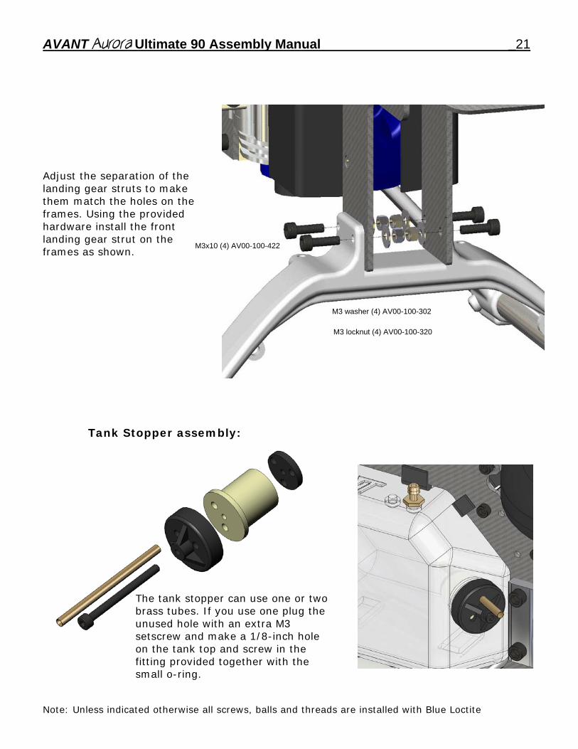
M3 locknut (4) AV00-100-320
M3 washer (4) AV00-100-302
AV00-100-422
Adjust the separation of the
landing gear struts to make them match the holes on theframes. Using the provided hardware install the front landing gear strut on the frames as shown.
M3x10 (4)
Tank Stopper assembly:
The tank stopper can use one or
ho
two
le
brass tubes. If you use one plug the unused hole with an extra M3 setscrew and make a 1/8-inch on the tank top and screw in the fitting provided together with the small o-ring.
Note: Unless indicated otherwise all screws, balls and threads are installed with Blue Loctite
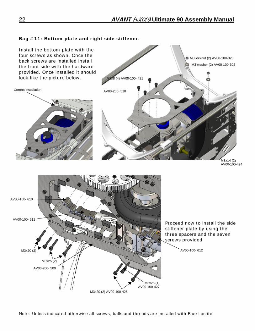
22 AVANT Aurora Ultimate 90 Assembly Manual Bag #11: Bottom plate and right side stiffener. Install the bottom plate with the four screws as shown. Once the back screws are installed install the front side with the hardware provided. Once installed it should look like the picture below.
M3 locknut (2) AV00-100-320
M3 washer (2) AV00-100-302
M3x8 (4) AV00-100- 421
Correct installation AV00-200- 510
M3x14 (2) AV00-100-424
AV00-100- 610 AV00-100- 611 Proceed now to install the side stiffener plate by using the three spacers and the seven screws provided.
AV00-200- 509
M3x20 (2) AV00-100-426
M3x25 (2)
M3x25 (1)AV00-100-427
AV00-100- 612 M3x20 (2)
Note: Unless indicated otherwise all screws, balls and threads are installed with Blue Loctite
AVANT Aurora Ultimate 90 Assembly Manual _23
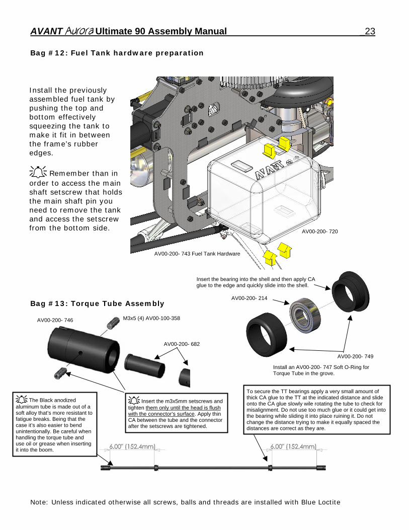
Bag #12: Fuel Tank hardware preparation
Install the previously assembled fuel tank by pushing the top and bottom effectively squeezing the tank to make it fit in between the frame’s rubber edges.
Remember than in order to access the main shaft setscrew that holds the main shaft pin you need to remove the tank and access the setscrew from the bottom side.
AV00-200- 720
AV00-200- 743 Fuel Tank Hardware Insert the bearing into the shell and then apply CA
glue to the edge and quickly slide into the shell. AV00-200- 214 Bag #13: Torque Tube Assembly
M3x5 (4) AV00-100-358 AV00-200- 746
AV00-200- 682
AV00-200- 749
Install an AV00-200- 747 Soft O-Ring for Torque Tube in the grove.
To secure the TT bearings apply a very small amount of thick CA glue to the TT at the indicated distance and slide onto the CA glue slowly wile rotating the tube to check for misalignment. Do not use too much glue or it could get into the bearing while sliding it into place ruining it. Do not change the distance trying to make it equally spaced the distances are correct as they are.
The Black anodized aluminum tube is made out of a soft alloy that’s more resistant to fatigue breaks. Being that the case it’s also easier to bend unintentionally. Be careful when handling the torque tube and use oil or grease when inserting it into the boom.
Insert the m3x5mm setscrews and tighten them only until the head is flush with the connector’s surface. Apply thin CA between the tube and the connector after the setscrews are tightened.
Note: Unless indicated otherwise all screws, balls and threads are installed with Blue Loctite
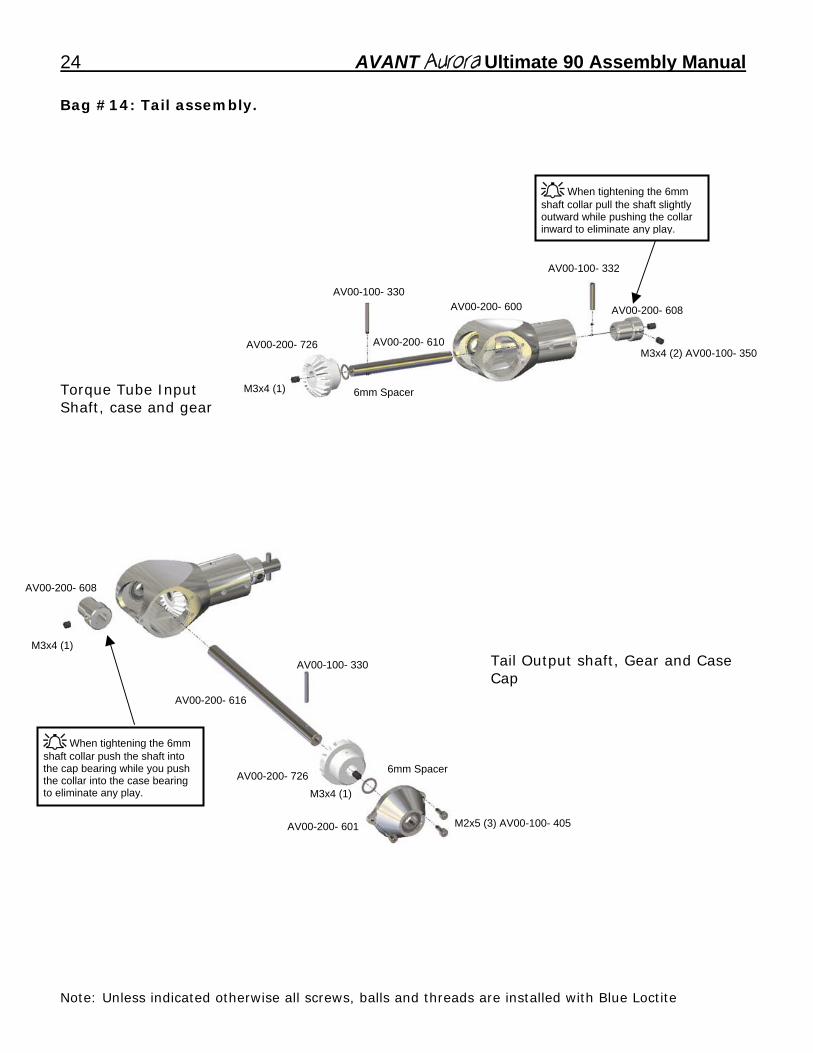
24 AVANT Aurora Ultimate 90 Assembly Manual Bag #14: Tail assembly.
AV00-100- 330
AV00-100- 332
When tightening the 6mm shaft collar pull the shaft slightly outward while pushing the collar inward to eliminate any play.
6mm Spacer M3x4 (1)
M3x4 (2) AV00-100- 350
AV00-200- 608
AV00-200- 610
AV00-200- 600
AV00-200- 726
Torque Tube Input Shaft, case and gear
Tail Output shaft, Gear and Case Cap
M3x4 (1)
M2x5 (3) AV00-100- 405
AV00-100- 330
6mm Spacer
AV00-200- 616
M3x4 (1)
When tightening the 6mm shaft collar push the shaft into the cap bearing while you push the collar into the case bearing to eliminate any play.
AV00-200- 726
AV00-200- 601
AV00-200- 608
Note: Unless indicated otherwise all screws, balls and threads are installed with Blue Loctite
AVANT Aurora Ultimate 90 Assembly Manual _25
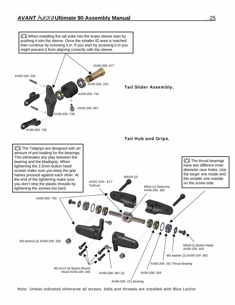
When installing the tail yoke into the brass sleeve start by pushing it into the sleeve. Once the smaller ID area is reached then continue by screwing it in. If you start by screwing it in you might prevent it from aligning correctly with the sleeve.
Tail Slider Assembly. Tail Hub and Grips.
AV00-200- 677
AV00-200- 735
AV00-200- 739
AV00-200- 742
AV00-200- 215
AV00-100- 334
AV00-200- 667
AV00-200- 750
AV00-200- 617 Tailhub
AV00-200- 667 (2)
AV00-200- 201 Thrust Bearing
AV00-200- 211 Bearing
AV00-200- 303
M3x8 (2) Button Head AV00-100- 442
M2.5x12 (4) Button RoundHead AV00-100- 440
M3x20 (2)
M3 locknut (2) AV00-100- 320
M3x4 (1) Setscrew AV00-100- 350
M3 washer (2) AV00-100- 302
The Tailgrips are designed with an amount of pre-loading for the bearings. This eliminates any play between the bearing and the bladegrip. When tightening the 2.5mm button head screws make sure you keep the grip halves pressed against each other. At the end of the tightening make sure you don’t strip the plastic threads by tightening the screws too hard.
The thrust bearings have two different inner diameter race holes. Use the larger one inside and the smaller one outside on the screw side.
Note: Unless indicated otherwise all screws, balls and threads are installed with Blue Loctite
26 AVANT Aurora Ultimate 90 Assembly Manual
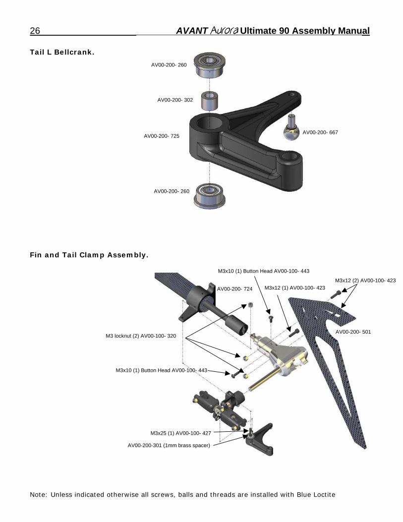
AV00-200- 725
AV00-200- 260
AV00-200- 260
AV00-200- 667
AV00-200- 302
Tail L Bellcrank. Fin and Tail Clamp Assembly.
AV00-200-301 (1mm brass spacer)
M3x25 (1) AV00-100- 427
M3x10 (1) Button Head AV00-100- 443
M3x12 (2) AV00-100- 423AV00-200- 724
AV00-200- 501M3 locknut (2) AV00-100- 320
M3x12 (1) AV00-100- 423
M3x10 (1) Button Head AV00-100- 443
Note: Unless indicated otherwise all screws, balls and threads are installed with Blue Loctite
AVANT Aurora Ultimate 90 Assembly Manual _27
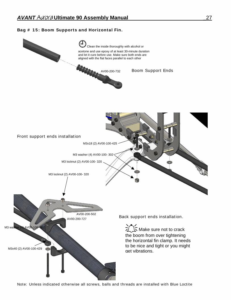
Bag # 15: Boom Supports and Horizontal Fin.
Boom Support Ends
Clean the inside thoroughly with alcohol or acetone and use epoxy of at least 30-minute duration and let it cure before use. Make sure both ends are aligned with the flat faces parallel to each other
AV00-200-732
Front support ends installation
Back support ends installation.
M3x18 (2) AV00-100-425
M3 washer (4) AV00-100- 302
M3x40 (2) AV00-100-429
AV00-200-727 AV00-200-502
M3 washer (4) AV00-100- 302
M3 locknut (2) AV00-100- 320
M3 locknut (2) AV00-100- 320
Make sure not to crack the boom from over tightening the horizontal fin clamp. It needs to be nice and tight or you might get vibrations.
Note: Unless indicated otherwise all screws, balls and threads are installed with Blue Loctite
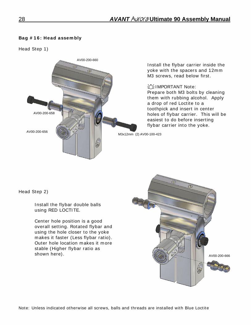
28 AVANT Aurora Ultimate 90 Assembly Manual Bag #16: Head assembly Head Step 1)
AV00-200-656 M3x12mm (2) AV00-100-423
AV00-200-658
AV00-200-660 Install the flybar carrier inside the yoke with the spacers and 12mm M3 screws, read below first.
IMPORTANT Note: Prepare both M3 bolts by cleaning them with rubbing alcohol. Apply a drop of red Loctite to a toothpick and insert in center holes of flybar carrier. This will be easiest to do before inserting flybar carrier into the yoke.
AV00-200-666
Head Step 2)
Install the flybar double balls
using RED LOCTITE. Center hole position is a good overall setting. Rotated flybar and using the hole closer to the yoke makes it faster (Less flybar ratio). Outer hole location makes it more stable (Higher flybar ratio as shown here).
Note: Unless indicated otherwise all screws, balls and threads are installed with Blue Loctite
AVANT Aurora Ultimate 90 Assembly Manual _29
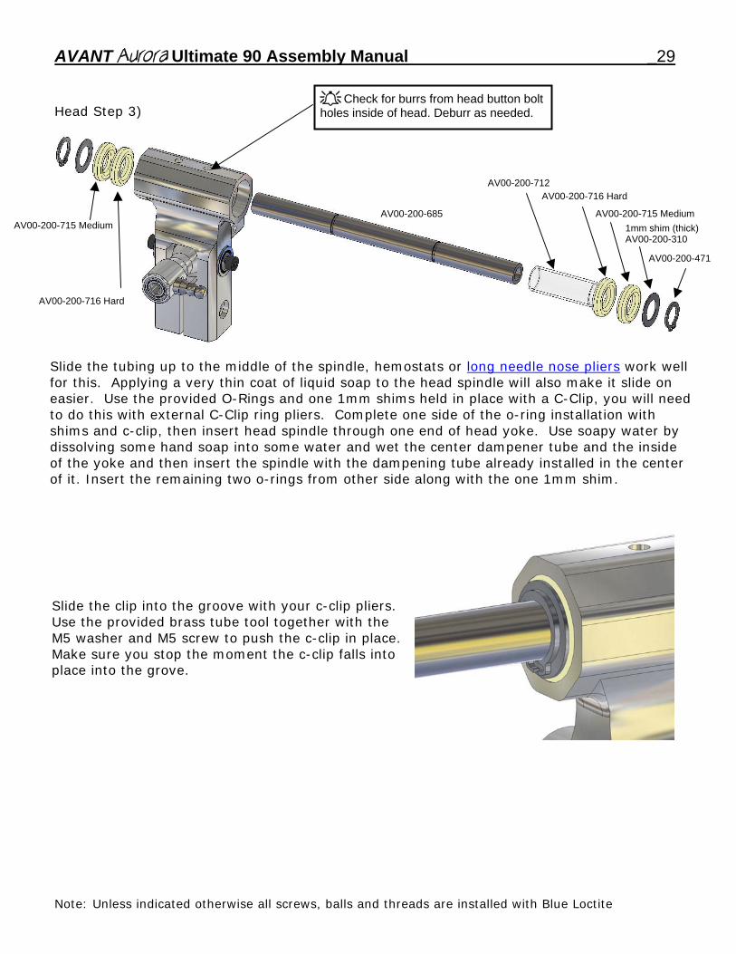
Head Step 3)
AV00-200-715 Medium
AV00-200-716 Hard
Check for burrs from head button bolt holes inside of head. Deburr as needed.
AV00-200-685
AV00-200-716 HardAV00-200-712
1mm shim (thick) AV00-200-310
AV00-200-471
AV00-200-715 Medium
Slide the tubing up to the middle of the spindle, hemostats or long needle nose pliers work well for this. Applying a very thin coat of liquid soap to the head spindle will also make it slide on easier. Use the provided O-Rings and one 1mm shims held in place with a C-Clip, you will need to do this with external C-Clip ring pliers. Complete one side of the o-ring installation with shims and c-clip, then insert head spindle through one end of head yoke. Use soapy water by dissolving some hand soap into some water and wet the center dampener tube and the inside of the yoke and then insert the spindle with the dampening tube already installed in the center of it. Insert the remaining two o-rings from other side along with the one 1mm shim.
Slide the clip into the groove with your c-clip pliers. Use the provided brass tube tool together with the M5 washer and M5 screw to push the c-clip in place. Make sure you stop the moment the c-clip falls into place into the grove.
Note: Unless indicated otherwise all screws, balls and threads are installed with Blue Loctite
30 AVANT Aurora Ultimate 90 Assembly Manual
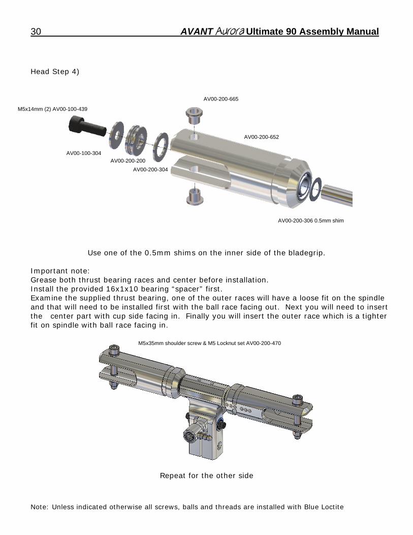
Head Step 4)
AV00-200-665
M5x14mm (2) AV00-100-439
AV00-200-652
AV00-100-304AV00-200-200
AV00-200-304
AV00-200-306 0.5mm shim
Use one of the 0.5mm shims on the inner side of the bladegrip.
Important note: Grease both thrust bearing races and center before installation. Install the provided 16x1x10 bearing “spacer” first. Examine the supplied thrust bearing, one of the outer races will have a loose fit on the spindle and that will need to be installed first with the ball race facing out. Next you will need to insert the center part with cup side facing in. Finally you will insert the outer race which is a tighter fit on spindle with ball race facing in.
M5x35mm shoulder screw & M5 Locknut set AV00-200-470
Repeat for the other side
Note: Unless indicated otherwise all screws, balls and threads are installed with Blue Loctite
AVANT Aurora Ultimate 90 Assembly Manual _31
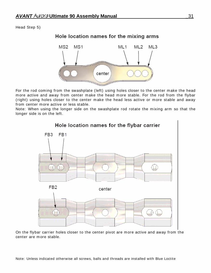
Head Step 5)
For the rod coming from the swashplate (left) using holes closer to the center make the head more active and away from center make the head more stable. For the rod from the flybar (right) using holes closer to the center make the head less active or more stable and away from center more active or less stable. Note: When using the longer side on the swashplate rod rotate the mixing arm so that the longer side is on the left.
On the flybar carrier holes closer to the center pivot are more active and away from the center are more stable.
Note: Unless indicated otherwise all screws, balls and threads are installed with Blue Loctite
32 AVANT Aurora Ultimate 90 Assembly Manual
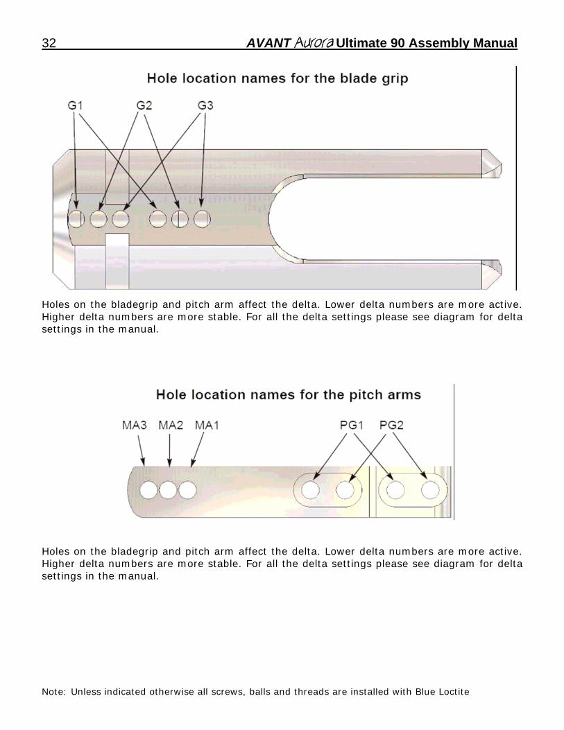
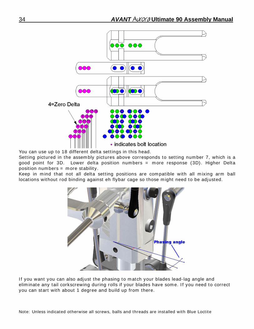
Holes on the bladegrip and pitch arm affect the delta. Lower delta numbers are more active. Higher delta numbers are more stable. For all the delta settings please see diagram for delta settings in the manual.
Holes on the bladegrip and pitch arm affect the delta. Lower delta numbers are more active. Higher delta numbers are more stable. For all the delta settings please see diagram for delta settings in the manual.
Note: Unless indicated otherwise all screws, balls and threads are installed with Blue Loctite
AVANT Aurora Ultimate 90 Assembly Manual _33
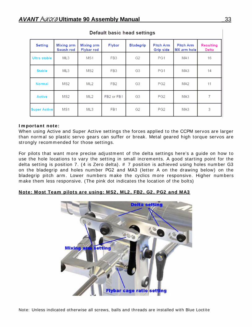
Important note: When using Active and Super Active settings the forces applied to the CCPM servos are larger than normal so plastic servo gears can suffer or break. Metal geared high torque servos are strongly recommended for those settings. For pilots that want more precise adjustment of the delta settings here’s a guide on how to use the hole locations to vary the setting in small increments. A good starting point for the delta setting is position 7. (4 is Zero delta). # 7 position is achieved using holes number G3 on the bladegrip and holes number PG2 and MA3 (letter A on the drawing below) on the bladegrip pitch arm. Lower numbers make the cyclics more responsive. Higher numbers make them less responsive. (The pink dot indicates the location of the bolts) Note: Most Team pilots are using: MS2, ML2, FB2, G2, PG2 and MA3
Note: Unless indicated otherwise all screws, balls and threads are installed with Blue Loctite
34 AVANT Aurora Ultimate 90 Assembly Manual
You can use up to 18 different delta settings in this head. Setting pictured in the assembly pictures above corresponds to setting number 7, which is a good point for 3D. Lower delta position numbers = more response (3D). Higher Delta position numbers = more stability. Keep in mind that not all delta setting positions are compatible with all mixing arm ball locations without rod binding against eh flybar cage so those might need to be adjusted.
If you want you can also adjust the phasing to match your blades lead-lag angle and eliminate any tail corkscrewing during rolls if your blades have some. If you need to correct you can start with about 1 degree and build up from there.
Note: Unless indicated otherwise all screws, balls and threads are installed with Blue Loctite
AVANT Aurora Ultimate 90 Assembly Manual _35
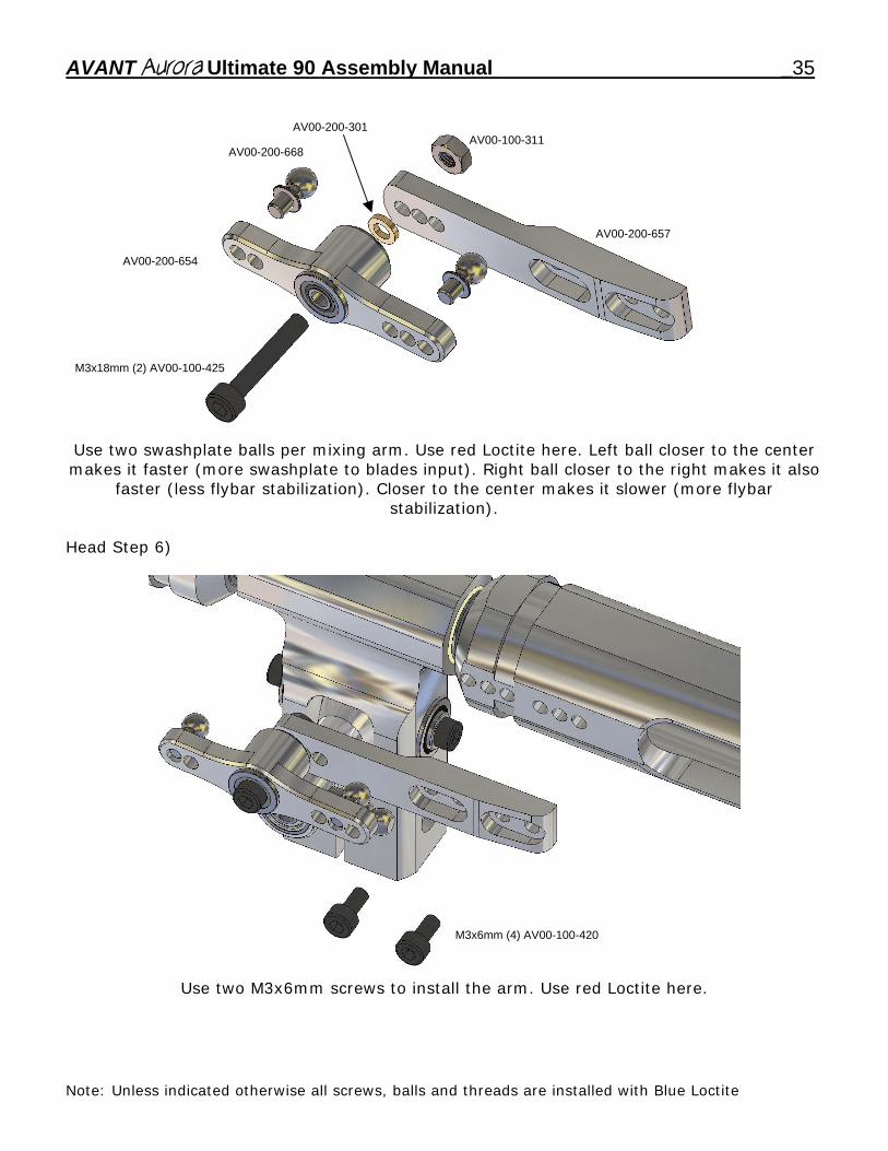
AV00-200-301AV00-100-311
AV00-200-668
AV00-200-657
AV00-200-654
M3x18mm (2) AV00-100-425
Use two swashplate balls per mixing arm. Use red Loctite here. Left ball closer to the center makes it faster (more swashplate to blades input). Right ball closer to the right makes it also
faster (less flybar stabilization). Closer to the center makes it slower (more flybar stabilization).
Head Step 6)
M3x6mm (4) AV00-100-420
Use two M3x6mm screws to install the arm. Use red Loctite here.
Note: Unless indicated otherwise all screws, balls and threads are installed with Blue Loctite
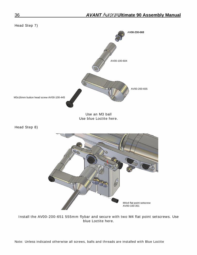
36 AVANT Aurora Ultimate 90 Assembly Manual Head Step 7)
AV00-200-668 V00-200-668
AV00-100-604
AV00-200-655
M3x16mm button head screw AV00-100-445
Use an M3 ball Use blue Loctite here.
Head Step 8)
M4x4 flat point setscrew AV00-100-351
Install the AV00-200-651 555mm flybar and secure with two M4 flat point setscrews. Use
blue Loctite here.
Note: Unless indicated otherwise all screws, balls and threads are installed with Blue Loctite
AVANT Aurora Ultimate 90 Assembly Manual _37
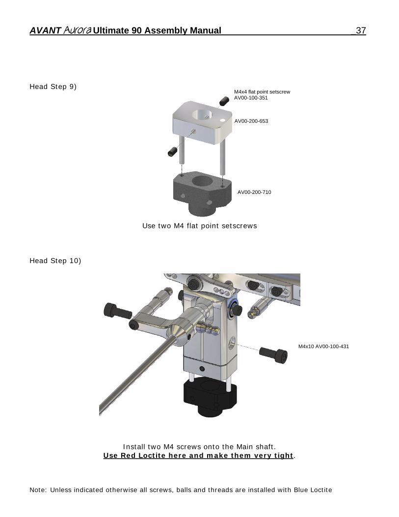
Head Step 9)
M4x4 flat point setscrew AV00-100-351
AV00-200-653
AV00-200-710
Use two M4 flat point setscrews Head Step 10)
M4x10 AV00-100-431
Install two M4 screws onto the Main shaft. Use Red Loctite here and make them very tight.
Note: Unless indicated otherwise all screws, balls and threads are installed with Blue Loctite
38 AVANT Aurora Ultimate 90 Assembly Manual Head Step 11)
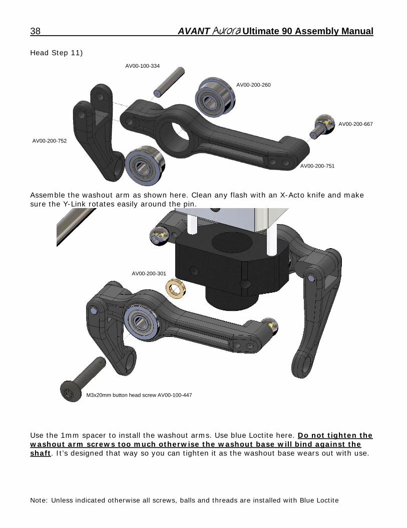
AV00-100-334
AV00-200-260
AV00-200-667
AV00-200-752
AV00-200-751
Assemble the washout arm as shown here. Clean any flash with an X-Acto knife and make sure the Y-Link rotates easily around the pin.
AV00-200-301
M3x20mm button head screw AV00-100-447
Use the 1mm spacer to install the washout arms. Use blue Loctite here. Do not tighten the washout arm screws too much otherwise the washout base will bind against the shaft. It’s designed that way so you can tighten it as the washout base wears out with use.
Note: Unless indicated otherwise all screws, balls and threads are installed with Blue Loctite
AVANT Aurora Ultimate 90 Assembly Manual _39
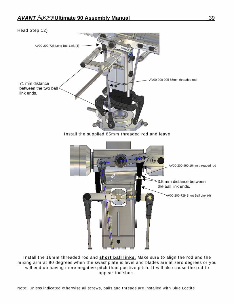
Head Step 12)
AV00-200-728 Long Ball Link (4)
71 mm distance between the two ball link ends.
AV00-200-995 85mm threaded rod
Install the supplied 85mm threaded rod and leave
3.5 mm distance between the ball link ends.
AV00-200-729 Short Ball Link (4)
AV00-200-990 16mm threaded rod
Install the 16mm threaded rod and short ball links. Make sure to align the rod and the
mixing arm at 90 degrees when the swashplate is level and blades are at zero degrees or you will end up having more negative pitch than positive pitch. It will also cause the rod to
appear too short.
Note: Unless indicated otherwise all screws, balls and threads are installed with Blue Loctite
40 AVANT Aurora Ultimate 90 Assembly Manual Head Step 13)
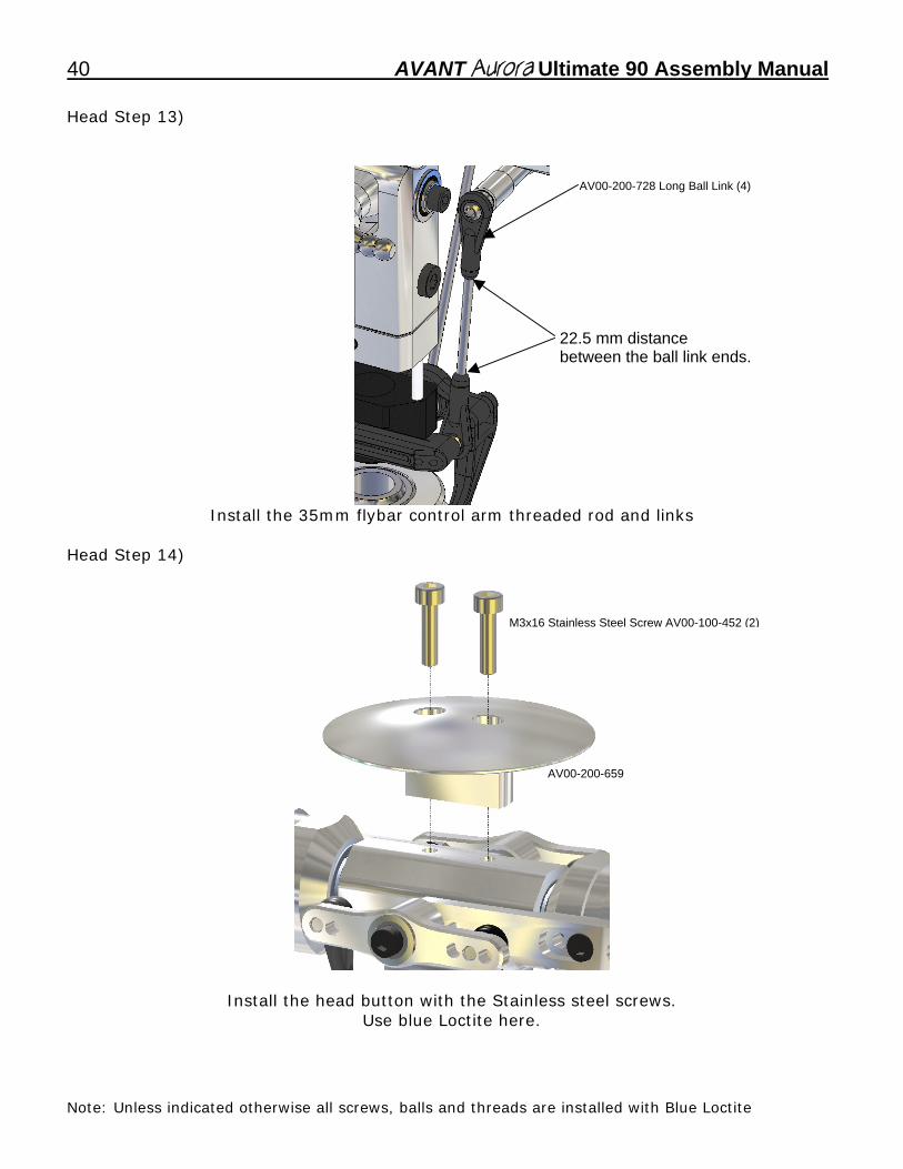
AV00-200-728 Long Ball Link (4)
22.5 mm distance between the ball link ends.
Install the 35mm flybar control arm threaded rod and links Head Step 14)
M3x16 Stainless Steel Screw AV00-100-452 (2)
AV00-200-659
Install the head button with the Stainless steel screws.
Use blue Loctite here.
Note: Unless indicated otherwise all screws, balls and threads are installed with Blue Loctite
AVANT Aurora Ultimate 90 Assembly Manual _41
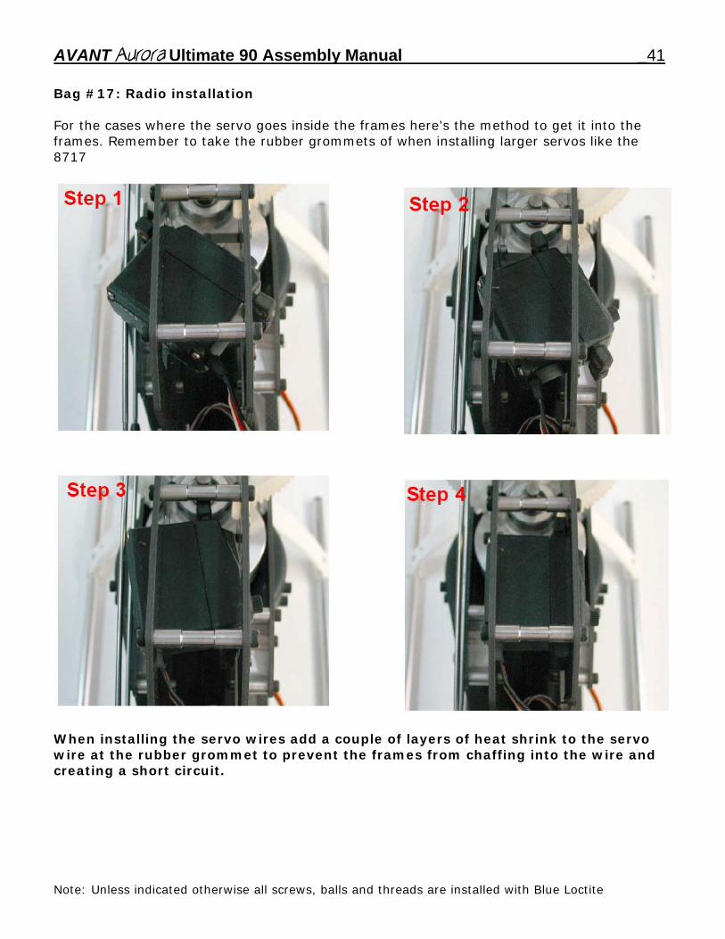
Bag #17: Radio installation For the cases where the servo goes inside the frames here’s the method to get it into the frames. Remember to take the rubber grommets of when installing larger servos like the 8717
When installing the servo wires add a couple of layers of heat shrink to the servo wire at the rubber grommet to prevent the frames from chaffing into the wire and creating a short circuit.
Note: Unless indicated otherwise all screws, balls and threads are installed with Blue Loctite
42 AVANT Aurora Ultimate 90 Assembly Manual
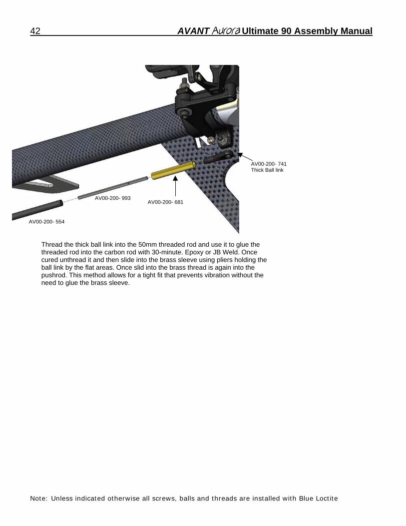
Thread the thick ball link into the 50mm threaded rod and use it to glue the threaded rod into the carbon rod with 30-minute. Epoxy or JB Weld. Once cured unthread it and then slide into the brass sleeve using pliers holding the ball link by the flat areas. Once slid into the brass thread is again into the pushrod. This method allows for a tight fit that prevents vibration without the need to glue the brass sleeve.
AV00-200- 554
AV00-200- 993
AV00-200- 741 Thick Ball link
AV00-200- 681
Note: Unless indicated otherwise all screws, balls and threads are installed with Blue Loctite
AVANT Aurora Ultimate 90 Assembly Manual _43
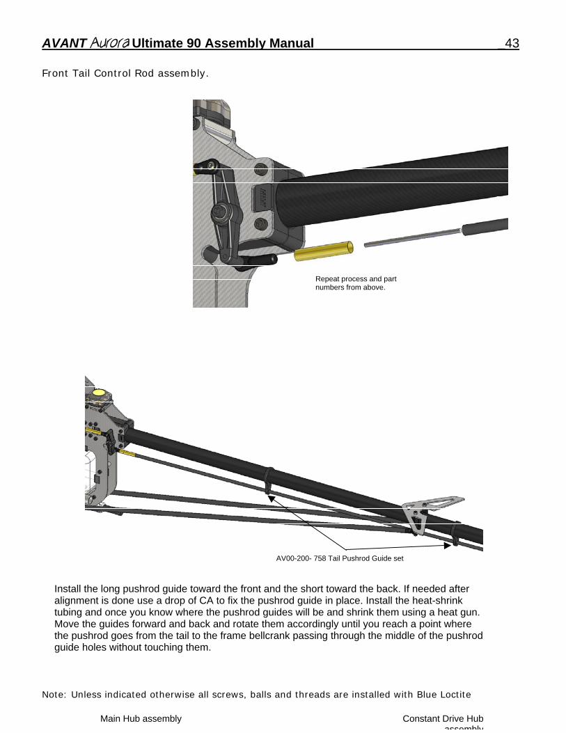
Front Tail Control Rod assembly. Repeat process and part
numbers from above.
AV00-200- 758 Tail Pushrod Guide set
Install the long pushrod guide toward the front and the short toward the back. If needed after alignment is done use a drop of CA to fix the pushrod guide in place. Install the heat-shrink tubing and once you know where the pushrod guides will be and shrink them using a heat gun. Move the guides forward and back and rotate them accordingly until you reach a point where the pushrod goes from the tail to the frame bellcrank passing through the middle of the pushrod guide holes without touching them.
Note: Unless indicated otherwise all screws, balls and threads are installed with Blue Loctite
Main Hub assembly Constant Drive Hubassembly
44 AVANT Aurora Ultimate 90 Assembly Manual
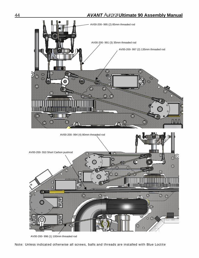
AV00-200- 995 (2) 85mm threaded rod
AV00-200- 997 (2) 135mm threaded rod
AV00-200- 991 (3) 35mm threaded rod
AV00-200- 553 Short Carbon pushrod
AV00-200- 994 (4) 80mm threaded rod
AV00-200- 996 (1) 100mm threaded rod
Note: Unless indicated otherwise all screws, balls and threads are installed with Blue Loctite
AVANT Aurora Ultimate 90 Assembly Manual _45
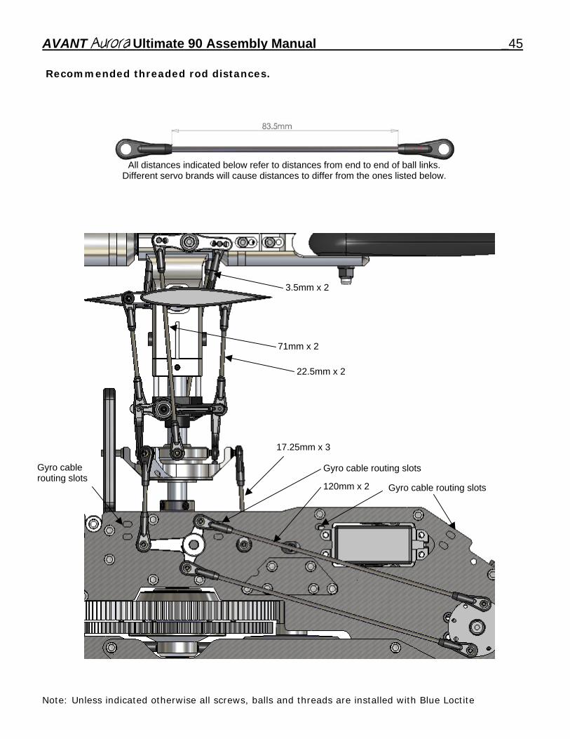
Recommended threaded rod distances.
All distances indicated below refer to distances from end to end of ball links. Different servo brands will cause distances to differ from the ones listed below.
Gyro cable routing slots
Gyro cable routing slots
Gyro cable routing slots120mm x 2
17.25mm x 3
71mm x 2
22.5mm x 2
3.5mm x 2
Note: Unless indicated otherwise all screws, balls and threads are installed with Blue Loctite
46 AVANT Aurora Ultimate 90 Assembly Manual
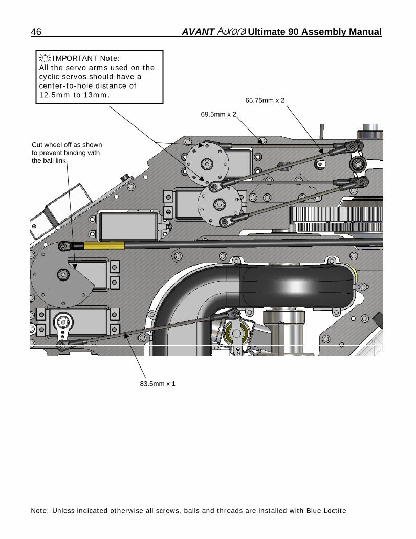
IMPORTANT Note: All the servo arms used on the cyclic servos should have a center-to-hole distance of 12.5mm to 13mm.
Cut wheel off as shown to prevent binding with the ball link
69.5mm x 2
65.75mm x 2
83.5mm x 1
Note: Unless indicated otherwise all screws, balls and threads are installed with Blue Loctite
AVANT Aurora Ultimate 90 Assembly Manual _47
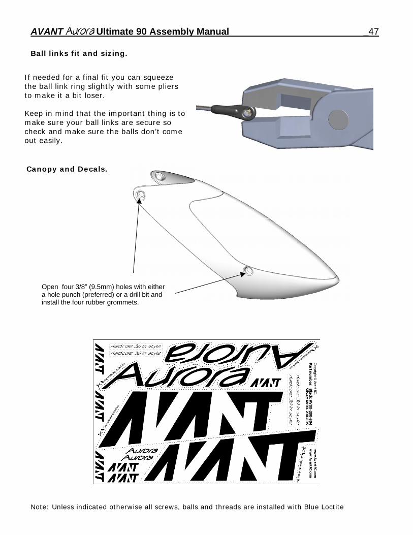
Ball links fit and sizing.
If needed for a final fit you can squeeze the ball link ring slightly with some pliers to make it a bit loser. Keep in mind that the important thing is to make sure your ball links are secure so check and make sure the balls don’t come out easily.
Canopy and Decals.
Open four 3/8” (9.5mm) holes with either a hole punch (preferred) or a drill bit and install the four rubber grommets.
Note: Unless indicated otherwise all screws, balls and threads are installed with Blue Loctite