Auxiliary Views Auxiliary views are often used to show inclined and oblique surfaces true size....
23
Auxiliary Views
-
Upload
louise-robbins -
Category
Documents
-
view
240 -
download
0
Transcript of Auxiliary Views Auxiliary views are often used to show inclined and oblique surfaces true size....

Auxiliary Views
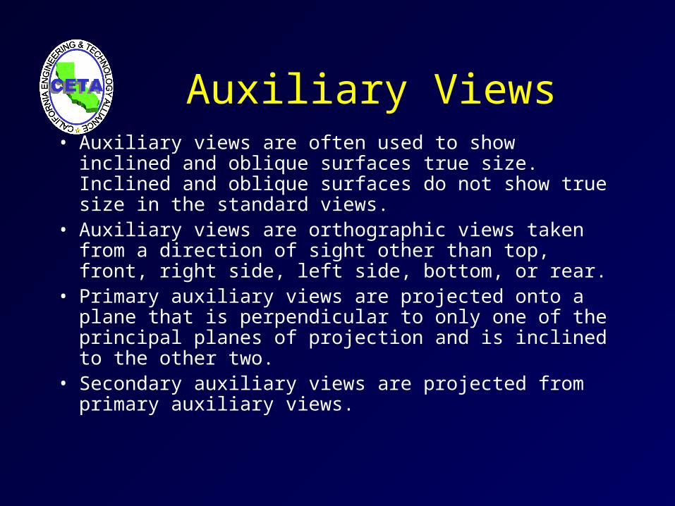
Auxiliary Views• Auxiliary views are often used to show inclined and
oblique surfaces true size. Inclined and oblique surfaces do not show true size in the standard views.
• Auxiliary views are orthographic views taken from a direction of sight other than top, front, right side, left side, bottom, or rear.
• Primary auxiliary views are projected onto a plane that is perpendicular to only one of the principal planes of projection and is inclined to the other two.
• Secondary auxiliary views are projected from primary auxiliary views.
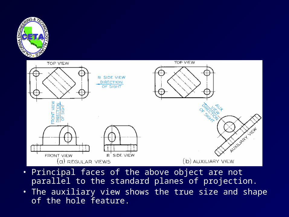
• Principal faces of the above object are not parallel to the standard planes of projection.
• The auxiliary view shows the true size and shape of the hole feature.
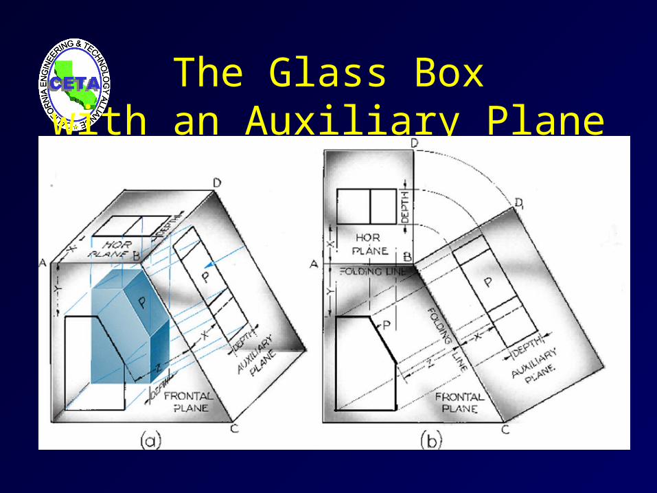
The Glass Boxwith an Auxiliary Plane
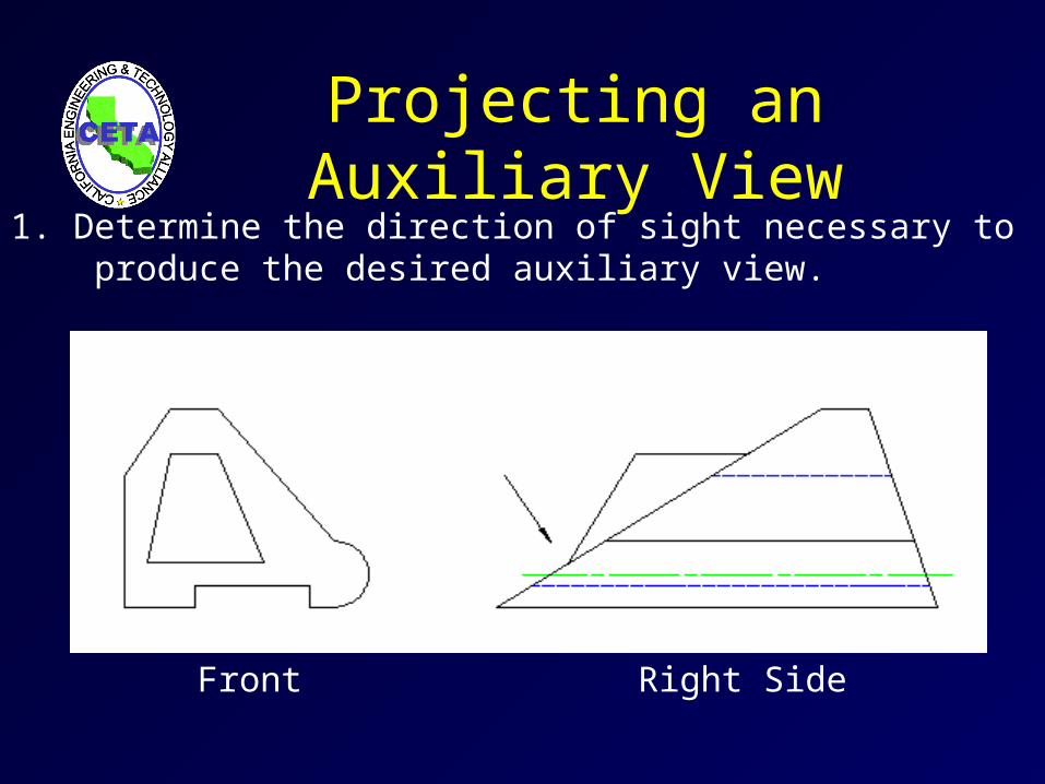
Projecting an Auxiliary View
Front Right Side
1. Determine the direction of sight necessary to produce the desired auxiliary view.
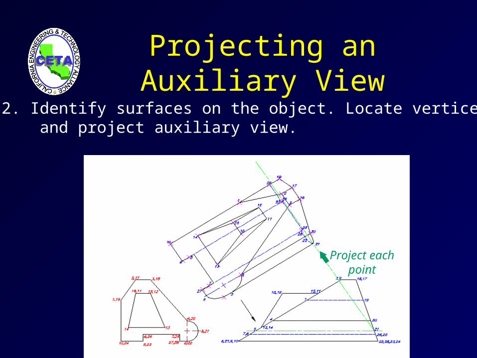
Project eachpoint
L.O.S.
Projecting an Auxiliary View
2. Identify surfaces on the object. Locate vertices and project auxiliary view.
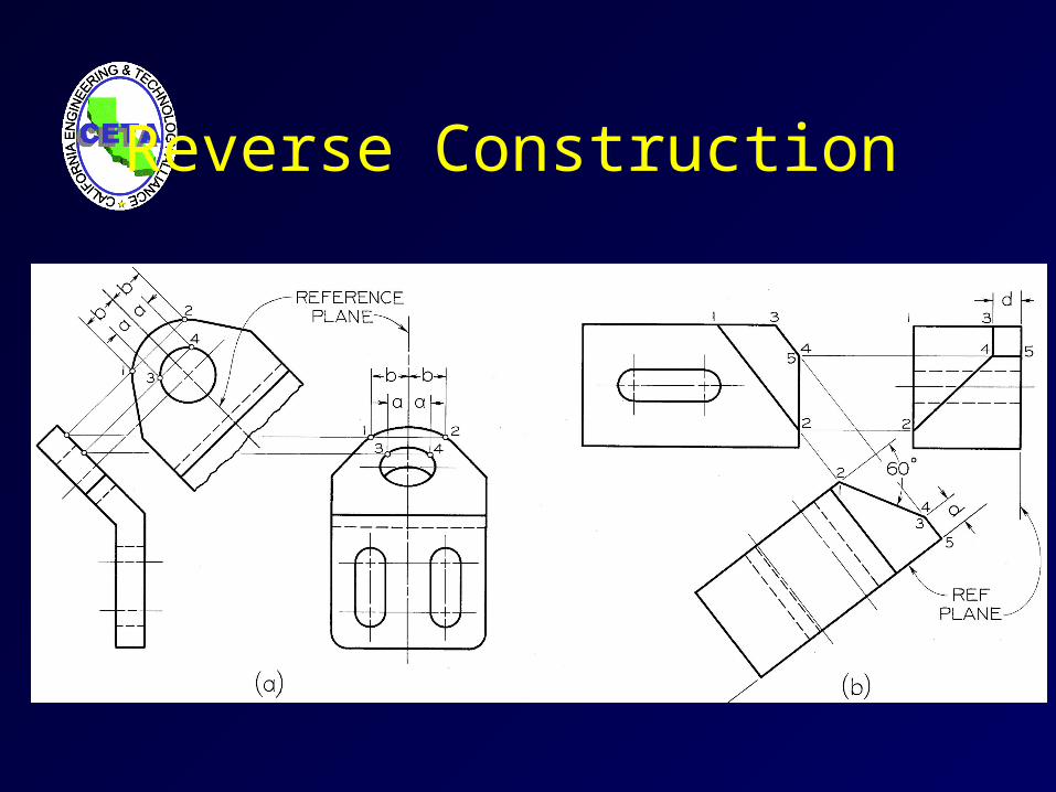
Reverse Construction
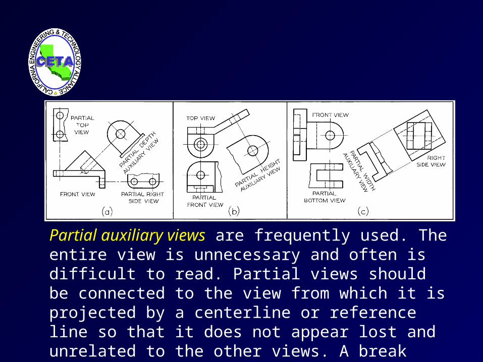
Partial auxiliary views are frequently used. The entire view is unnecessary and often is difficult to read. Partial views should be connected to the view from which it is projected by a centerline or reference line so that it does not appear lost and unrelated to the other views. A break line can be used to indicate that the view is a partial view.
Descriptive Geometry
Uses auxiliary views to solve engineering problems. The four following auxiliary views are basic to solving problems in descriptive geometry:
1. Auxiliary view to show the true length of a line. 2. Auxiliary view to show the point view of a line.
3. Auxiliary view to show the edge view of a plane.4. Auxiliary view to show the true size of a plane.
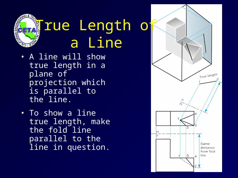
True Length of a Line
• A line will show true length in a plane of projection which is parallel to the line.
• To show a line true length, make the fold line parallel to the line in question.
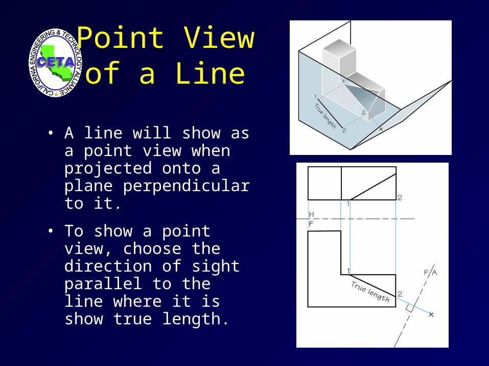
Point Viewof a Line
• A line will show as a point view when projected onto a plane perpendicular to it.
• To show a point view, choose the direction of sight parallel to the line where it is show true length.
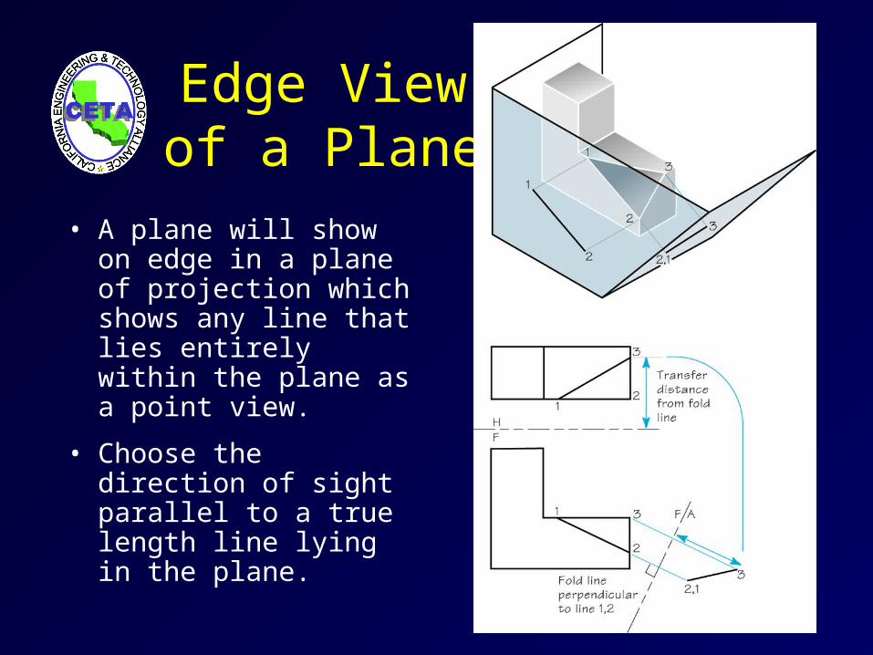
Edge View of a Plane
• A plane will show on edge in a plane of projection which shows any line that lies entirely within the plane as a point view.
• Choose the direction of sight parallel to a true length line lying in the plane.
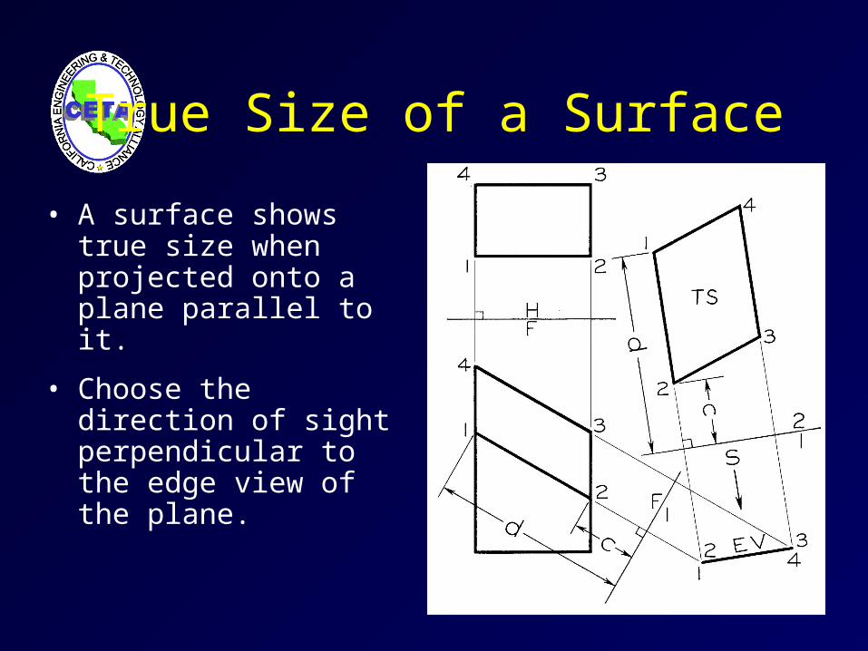
True Size of a Surface
• A surface shows true size when projected onto a plane parallel to it.
• Choose the direction of sight perpendicular to the edge view of the plane.
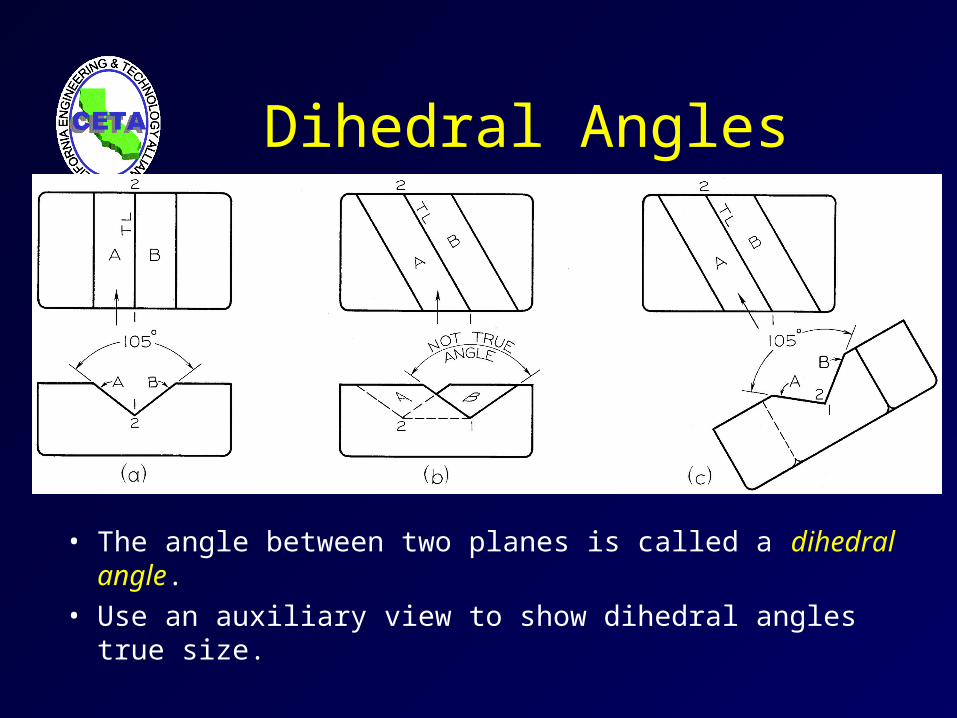
Dihedral Angles
• The angle between two planes is called a dihedral angle.
• Use an auxiliary view to show dihedral angles true size.
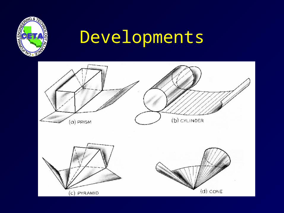
Developments
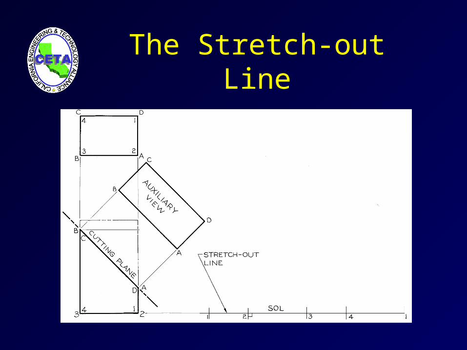
The Stretch-out Line
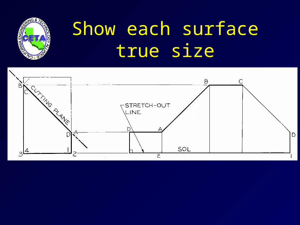
Show each surface true size
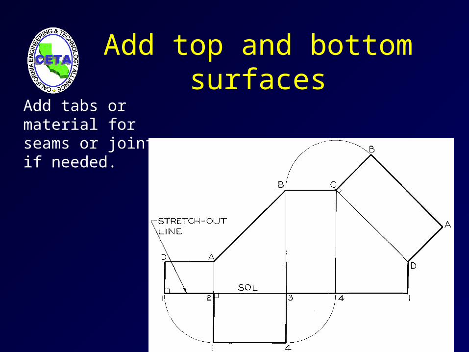
Add top and bottom surfacesAdd tabs or material for seams or joints if needed.
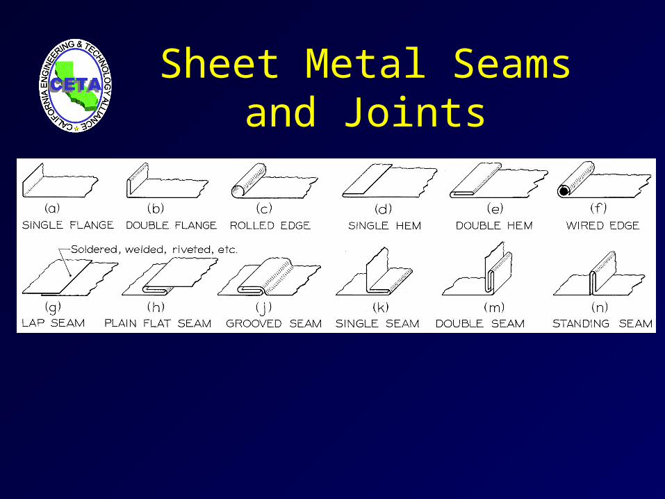
Sheet Metal Seams and Joints
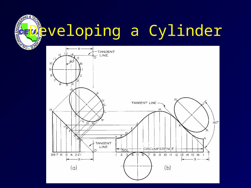
Developing a Cylinder
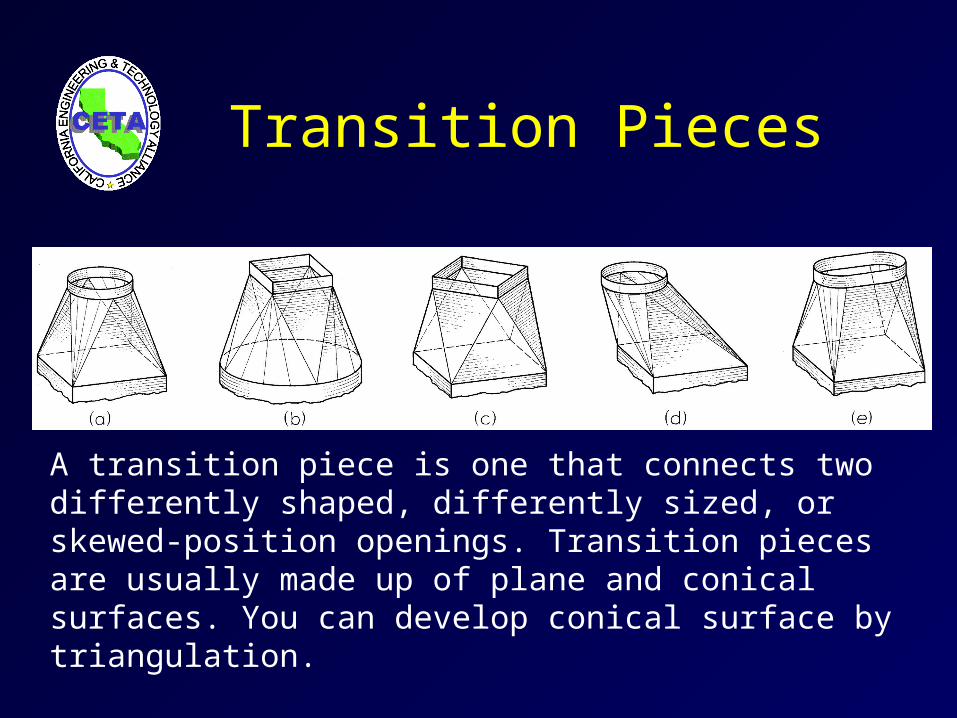
Transition Pieces
A transition piece is one that connects two differently shaped, differently sized, or skewed-position openings. Transition pieces are usually made up of plane and conical surfaces. You can develop conical surface by triangulation.
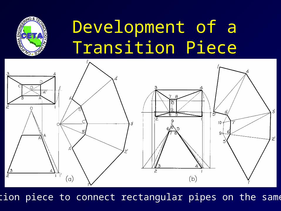
Development of aTransition Piece
Transition piece to connect rectangular pipes on the same axis.
Summary
• Auxiliary views can be drawn to show the true size and shape of inclined and oblique surfaces.
• Auxiliary views are the primary tool used in descriptive geometry. Four auxiliary views which are important to understand how to produce are:– True Length of a Line– Point View of a Line– Edge View of a Plane– True Size of a Plane
• Developments are produced by unrolling or unfolding the surfaces of an object. To produce a development you use auxiliary view techniques to show the surfaces true size where they are unrolled.