AUTONOMOUS DIRECTIONAL SOLIDIFICATION … directional solidification (ADS) ... up to 18 cm in...
10
AUTONOMOUS DIRECTIONAL SOLIDIFICATION (ADS), A NOVEL CASTING TECHNIQUE FOR SINGLE CRYSTAL COMPONENTS I.A. Wagner and P.R. Sahm GieBerei-Institut, RWTH Aachen IntzestraDe 5, 52072 Aachen, Germany Autonomous directional solidification (ADS) for producing single crystal turbine blades utilizes the peculiarity of certain Ni-base superalloy-ceramic shell combinations to highly undercool. The single crystal directional solidification process is initiated by nucleation at typically 20 K under- cooling temperatures. The results obtained from work with cylindrical bars delivered the basis for the successful single crystal solidification of solid and hollow aero-engine blades up to 18 cm in length. First trials of casting large turbine blades for application in stationary gas turbines have been done, accompanied by a numerical process simulation, Compared to the conventional techniques, the essential advantages of an optimized ADS process are a shorter processing time and a finer microstructure, enabling a shorter duration of heat treatment. The casting of single crystal (SC) turbine blades for aero- engine application is widely used today [ 11. The conventional technique is well developed but not optimized into the casting of large turbine blades for application in stationary gas turbines [2,3]. In addition, new alloys have been developed [4]. Due to the limitations of the conventional technique and the enormous production costs, alternative processes attract special interest. At the Foundry-Institute of the Technical University of Aachen, the Autonomous Directional Solidification (ADS) process has been developed. The process is based on the peculiarity to undercool the superalloy in the ceramic shell mold to a certain level, leading to a rapid solidification after nucleation at the bottom of the mold. It was first presented in 1981 [5]. The authors then obtained several directionally solidified turbine blades. Subsequent work in this area resulted in the development of a shell mold system which enabled efficient thermal under- cooling of several Ni-base superalloys [6]. The quality of the single crystals was investigated using various techniques. A y-ray diffraction analysis of the specimen showed an excellent quality of the single crystal microstructure [7]. The Suprmlloys 1996 distortions of the main crystallographic orientation measured less than 5O. These results are the basis for the current and ongoing research on the process engineering, characterization and control of the dynamic solidification technique ADS. Experimental Shell mold Two different ceramic system approaches have been followed. The basic material was always alumina with the binders either AlOOH or silicasol. The shell molds were, produced by standard investment casting procedures. The thickness of the shell molds was about 6 mm. The assemblies were dewaxed in a steam autoclave and fired at temperatures between 1200°C and 1450°C. After preheating the ceramic shell mold within the heating device, the separately melted superalloy was poured into the shell mold. The heater was then switched off, see Figure 1 for the basic set-up. i Tliq. Cu-Chill --- Figure 1: Schematic illustration of the ADS process with a typical temperature distribution. Thermal undercooling of the melt is used to accelerate the solidification. Edited by R. D. Kissinger, D. J. Deye, D. L. Anton, A. D. Cetel, M. V. Nathal, r. M. Pollock, and D. A. Woodford The Mmerals, Metals &Materials Society, 1996 497
Transcript of AUTONOMOUS DIRECTIONAL SOLIDIFICATION … directional solidification (ADS) ... up to 18 cm in...
AUTONOMOUS DIRECTIONAL SOLIDIFICATION (ADS),
A NOVEL CASTING TECHNIQUE FOR SINGLE CRYSTAL COMPONENTS
I.A. Wagner and P.R. Sahm
GieBerei-Institut, RWTH Aachen
IntzestraDe 5, 52072 Aachen, Germany
Autonomous directional solidification (ADS) for producing single crystal turbine blades utilizes the peculiarity of certain Ni-base superalloy-ceramic shell combinations to highly undercool. The single crystal directional solidification process is initiated by nucleation at typically 20 K under- cooling temperatures. The results obtained from work with cylindrical bars delivered the basis for the successful single crystal solidification of solid and hollow aero-engine blades up to 18 cm in length. First trials of casting large turbine blades for application in stationary gas turbines have been done, accompanied by a numerical process simulation,
Compared to the conventional techniques, the essential advantages of an optimized ADS process are a shorter processing time and a finer microstructure, enabling a shorter duration of heat treatment.
The casting of single crystal (SC) turbine blades for aero- engine application is widely used today [ 11. The conventional technique is well developed but not optimized into the casting of large turbine blades for application in stationary gas turbines [2,3]. In addition, new alloys have been developed [4]. Due to the limitations of the conventional technique and the enormous production costs, alternative processes attract special interest.
At the Foundry-Institute of the Technical University of Aachen, the Autonomous Directional Solidification (ADS) process has been developed. The process is based on the peculiarity to undercool the superalloy in the ceramic shell mold to a certain level, leading to a rapid solidification after nucleation at the bottom of the mold. It was first presented in 1981 [5]. The authors then obtained several directionally solidified turbine blades.
Subsequent work in this area resulted in the development of a shell mold system which enabled efficient thermal under- cooling of several Ni-base superalloys [6]. The quality of the single crystals was investigated using various techniques. A
y-ray diffraction analysis of the specimen showed an excellent quality of the single crystal microstructure [7]. The
Suprmlloys 1996
distortions of the main crystallographic orientation measured less than 5O.
These results are the basis for the current and ongoing research on the process engineering, characterization and control of the dynamic solidification technique ADS.
Experimental
Shell mold
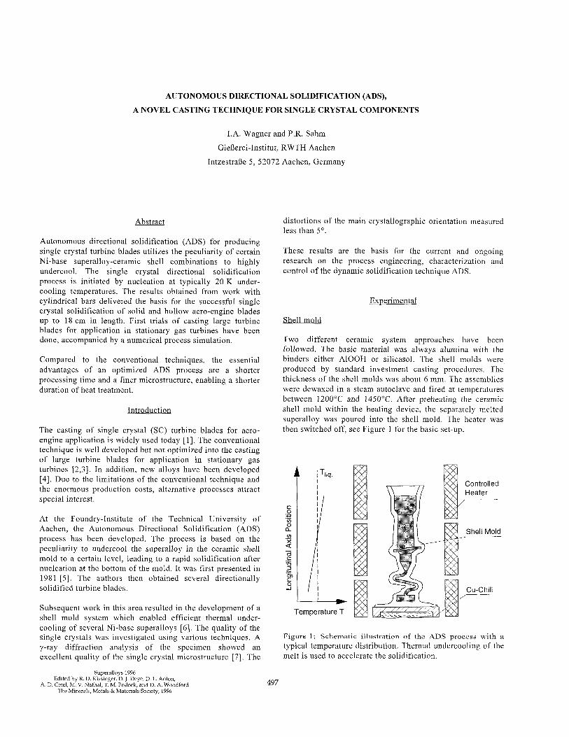
Two different ceramic system approaches have been followed. The basic material was always alumina with the binders either AlOOH or silicasol. The shell molds were, produced by standard investment casting procedures. The thickness of the shell molds was about 6 mm. The assemblies were dewaxed in a steam autoclave and fired at temperatures between 1200°C and 1450°C. After preheating the ceramic shell mold within the heating device, the separately melted superalloy was poured into the shell mold. The heater was then switched off, see Figure 1 for the basic set-up.
i Tliq.
Cu-Chill ---
Figure 1: Schematic illustration of the ADS process with a typical temperature distribution. Thermal undercooling of the melt is used to accelerate the solidification.
Edited by R. D. Kissinger, D. J. Deye, D. L. Anton, A. D. Cetel, M. V. Nathal, r. M. Pollock, and D. A. Woodford
The Mmerals, Metals &Materials Society, 1996 497
Numerous experiments have been carried out in an attempt to investigate the microstructure as a function of the process parameters, experimental set-up, geometry and size of the specimen.
Cvlindrical snecimens
Single bars of 15 mm in diameter and 20 cm in length were cast for fundamental investigations. Temperatures were measured using precisely positioned Pt-Rh30/Pt-Rh6 ther- mocouples. The wires which were 0.2 mm in diameter were protected by high purity alumina tubes. The temperature distribution during solidification was measured along the vertical axis of the specimens. Two different furnaces suitable for directional solidification control were used.
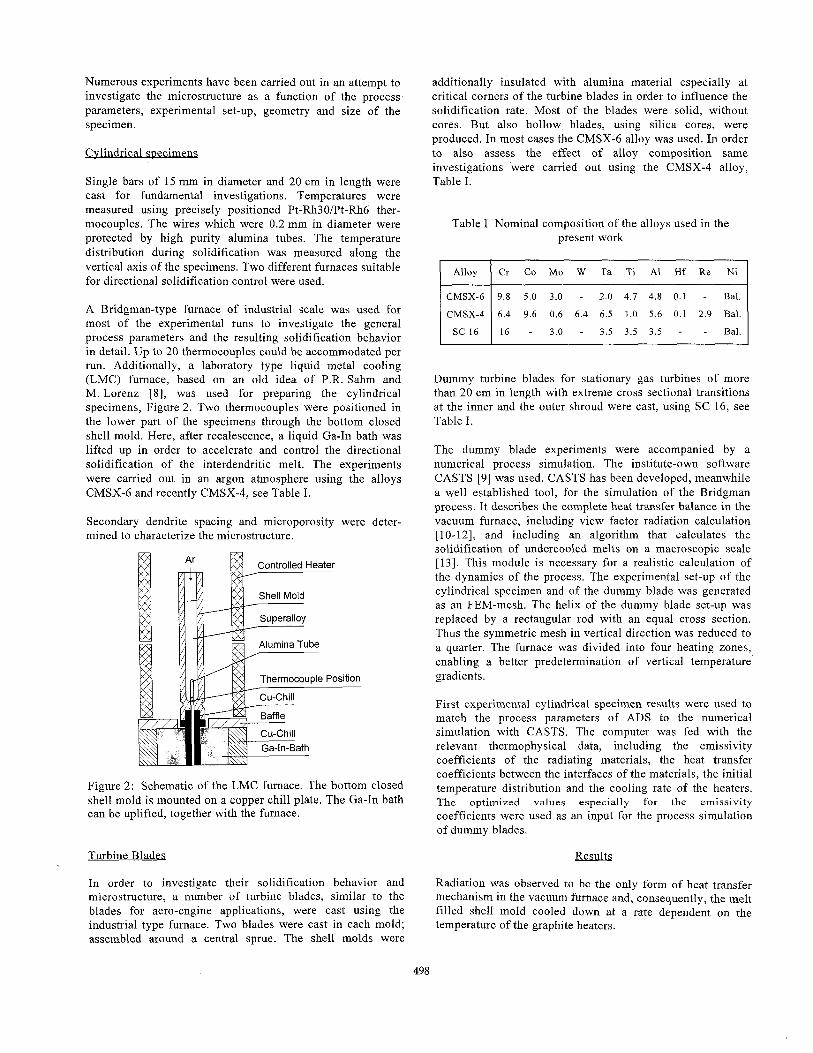
A Bridgman-type furnace of industrial scale was used for most of the experimental runs to investigate the general process parameters and the resulting solidification behavior in detail. Up to 20 thermocouples could be accommodated per run. Additionally, a laboratory type liquid metal cooling (LMC) furnace, based on an old idea of P.R. Sahm and M. Lorenz 181, was used for preparing the cylindrical specimens, Figure 2. Two thermocouples were positioned in the lower part of the specimens through the bottom closed shell mold. Here, after recalescence, a liquid Ga-In bath was lifted up in order to accelerate and control the directional solidification of the interdendritic melt. The experiments were carried out in an argon atmosphere using the alloys CMSX-6 and recently CMSX-4, see Table I.
Secondary dendrite spacing and microporosity were deter- mined to characterize the microstructure.
Figure 2: Schematic of the LMC furnace. The bottom closed shell mold is mounted on a copper chill plate. The Ga-In bath can be uplifted, together with the furnace.
Turbine Blades
In order to investigate their solidification behavior and microstructure, a number of turbine blades, similar to the blades for aero-engine applications, were cast using the industrial type furnace. Two blades were cast in each mold; assembled around a central sprue. The shell molds were
additionally insulated with alumina material especially at critical corners of the turbine blades in order to influence the solidification rate. Most of the blades were solid, without cores. But also hollow blades, using silica cores, were produced. In most cases the CMSX-6 alloy was used. In order to also assess the effect of alloy composition same investigations were carried out using the CMSX-4 alloy, Table I.
Table I Nominal composition of the alloys used in the present work
< CMSX-4 6.4 9.6 0.6 6.4 6.5 1.0 5.6 0.1 2.9 Bal.
Dummy turbine blades for stationary gas turbines of more than 20 cm in length with extreme cross sectional transitions at the inner and the outer shroud were cast, using SC 16, see Table I.
The dummy blade experiments were accompanied by a numerical process simulation. The institute-own software CASTS [9] was used. CASTS has been developed, meanwhile a well established tool, for the simulation of the Bridgman process. It describes the complete heat transfer balance in the vacuum furnace, including view factor radiation calculation [lo-121, and including an algorithm that calculates the solidification of undercooled melts on a macroscopic scale [ 131. This module is necessary for a realistic calculation of the dynamics of the process. The experimental set-up of the cylindrical specimen and of the dummy blade was generated as an FEM-mesh. The helix of the dummy blade set-up was replaced by a rectangular rod with an equal cross section. Thus the symmetric mesh in vertical direction was reduced to a quarter. The furnace was divided into four heating zones, enabling a better predetermination of vertical temperature gradients.
First experimental cylindrical specimen results were used to match the process parameters of ADS to the numerical simulation with CASTS. The computer was fed with the relevant thermophysical data, including the emissivity coefficients of the radiating materials, the heat transfer coefficients between the interfaces of the materials, the initial temperature distribution and the cooling rate of the heaters. The optimized values especially for the emissivity
coefficients were used as an input for the process simulation of dummy blades.
Results
Radiation was observed to be the only form of heat transfer mechanism in the vacuum furnace and, consequently, the melt filled shell mold cooled down at a rate dependent on the temperature of the graphite heaters.
498
Cvlindrical specimens
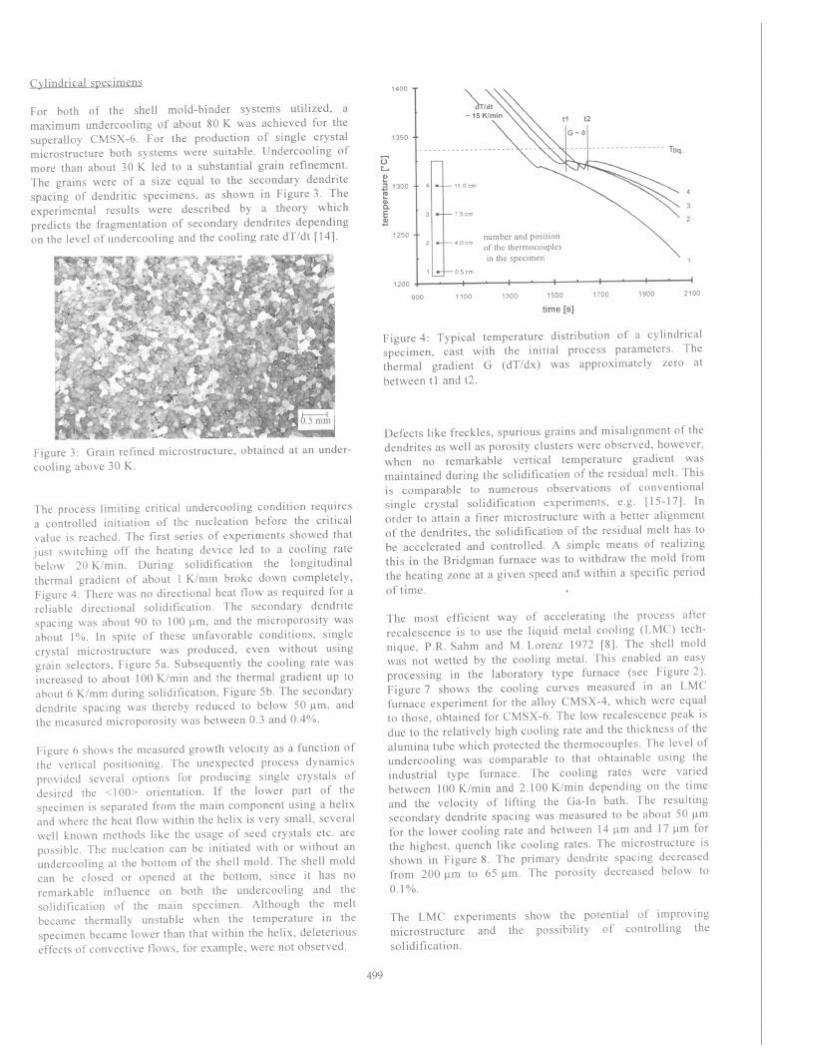
For both of the shell mold-binder systems utilized, a maximum undercooling of about 80 K was achieved for the superalloy CMSX-6. For the production of single crystal microstructure both systems were suitable. Undercooling of more than about 30 K led to a substantial grain refinement. The grains were of a size equal to the secondary dendrite spacing of dendritic specimens, as shown in Figure 3. The experimental results were described by a theory which predicts the fragmentation of secondary dendrites depending on the level of undercooling and the cooling rate dT/dt [ 141.
Figure 3. Gram refined mrcrostructure, obtained at an under- cooling above 30 K.
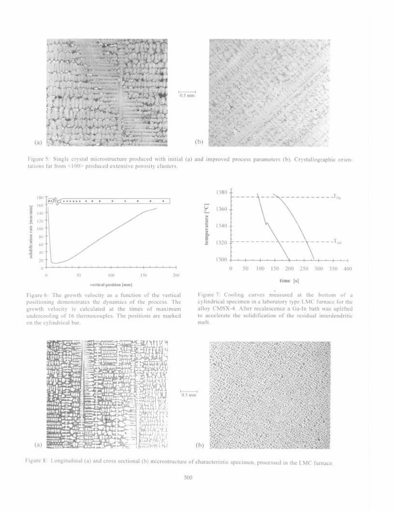
The process limiting critical undercooling condition requires a controlled initiation of the nucleation before the critical value is reached. The first series of experiments showed that just switching off the heating device led to a cooling rate below 20 Kimin. During solidification the longitudinal thermal gradient of about 1 K/mm broke down completely, Figure 4. There was no directional heat flow as required for a reliable directional solidification. The secondary dendrite spacing was about 90 to 100 pm, and the microporosity was about 1%. In spite of these unfavorable conditions, single crystal microstructure was produced, even without using grain selectors, Figure 5a. Subsequently the cooling rate was increased to about 100 Kimin and the thermal gradient up to about 6 K/mm during solidification, Figure 5b. The secondary dendrite spacing was thereby reduced to below 50 pm, and the measured microporosity was between 0.3 and 0.4%.
Figure 6 shows the measured growth velocity as a function of the vertical positioning. The unexpected process dynamics provided several options for producing single crystals of desired the <loo> orientation. If the lower part of the specimen is separated from the main component using a helix and where the heat flow within the helix is very small, several well known methods like the usage of seed crystals etc. are possible. The nucleation can be initiated with or without an undercooling at the bottom of the shell mold. The shell mold can be closed or opened at the bottom, since it has no remarkable influence on both the undercooling and the solidificatton of the main specimen. Although the melt became thermally unstable when the temperature in the specimen became lower than that within the helix, deleterious effects of convective flows, for example, were not observed.
1400 -
number and position of the thermocouples in the specimen
900 ,100 ,300 ,500 ,700 ,900 2100
time [s]
Figure 4: Typical temperature distribution of a cylindrical specimen, cast with the initial process parameters. The thermal gradient G (dT/dx) was approximately zero at between tl and t2.
Defects like freckles, spurious grains and misalignment of the dendrites as well as porosity clusters were observed, however, when no remarkable vertical temperature gradient was maintained during the solidification of the residual melt. This is comparable to numerous observations of conventional single crystal solidification experiments, e.g. [15-l 71. In order to attain a finer microstructure with a better alignment of the dendrites, the solidification of the residual melt has to be accelerated and controlled. A simple means of realizing this in the Bridgman furnace was to withdraw the mold from the heating zone at a given speed and within a specific period of time. .
The most efficient way of accelerating the process after recalescence is to use the liquid metal cooling (LMC) tech- nique, P.R. Sahm and M. Lorenz 1972 [S]. The shell mold was not wetted by the cooling metal. This enabled an easy processing in the laboratory type furnace (see Figure 2). Figure 7 shows the cooling curves measured in an LMC furnace experiment for the alloy CMSX-4, which were equal to those, obtained for CMSX-6. The low recalescence peak is due to the relatively high cooling rate and the thickness of the alumina tube which protected the thermocouples. The level of undercooling was comparable to that obtainable using the industrial type furnace. The cooling rates were varied between 100 Kimin and 2.100 Kimin depending on the time and the velocity of lifting the Ga-In bath. The resulting secondary dendrite spacing was measured to be about 50 pm for the lower cooling rate and between 14 urn and 17 pm for the highest, quench like cooling rates. The microstructure is shown in Figure 8. The primary dendrite spacing decreased from 200 pm to 65 pm. The porosity decreased below to 0.1%.
The LMC experiments show the potential of improving microstructure and the possibility of controlling the solidification.
499
.I .,*_ ). _. . . ,.v,
(r I, -- ># - *,+.s’
‘>f 1” I _: ?, . .+ 1,”
‘ ,, .,; ,. \<‘I “. I
;s> * .;q ,*,.a”$“‘: ‘ ~b,,, ‘*
:*-+ k .i A ’
.A c , :‘̂ c T ,_? .,. ” i *. . ,> r * . _ *?%,‘-f
-w-q ..: .*.a*,. ..j :
“-“F . ..$ 4, cc,i,..$e, ‘i ,w .‘I .J\,r ,,
* I . . . .y~I-“*%‘xup ‘,‘., *. ;‘. i:.‘ ;.rqe J k t yA p$i ” I
v‘ .-i, cI.+-l .c,, .. . I.Y r,y-&,, j 7. L.-y * Ch 7) -.w-. *
4 ;~*&*y:‘~& j ,.;*;?‘ :-.: . ‘Y. ” 1 +$ :- 5 ZF ~~
: & - ., i ,l ‘Z ‘0.5 WA.- ‘
p c ^J ,q+,.y*p; :;-
-b’, .%a.
k l\(U,. *.dxA : ,-J.’ 1
~ 37 (.,I_ 1 0-8. r.w , ,, @ ,
j+ ~.-$+4<...?rg4>“/ h*.’ : ;I *I I. “.‘V
f
<.. *I.
*“; =&r+.-.
: “z.Li ,&,, *&..<+;: y>* sI ” :> \..A* S’
i If a_ ‘$ ,/ ; **- i Q-9 ** \ 7 ‘T. #
,‘;“ ‘* _ . . . * .T
(a) ,, “5 I * .qdr~ * )o*.*.,; .- i
, .‘, ‘-’ 4 ,_I ,pr*., ,rt~ ““. _ ” ..?I” _I.
PI, “..#< 8. t
I ,” * d . -u, @I
Figure 5: Single crystal microstructure produced with initial (a) and improved process parameters (b). Crystallographic orien- tations far from <loo> produced extensive porosity clusters.
““i ,“‘I “‘, i ‘,“I 0 50 100 I50 200
vertical position [mm1
Figure 6: The growth velocity as a function of the vertical positioning demonstrates the dynamics of the process. The growth velocity is calculated at the times of maximum undercooling of 16 thermocouples. The positions are marked on the cylindrical bar.
0.5 mm
E 1360
E 2 2 1340 & E 2 1320
0 50 100 150 200 250 300 350 400
time [s]
. Figure 7: Cooling curves measured at the bottom of a cylindrical specimen in a laboratory type LMC furnace for the alloy CMSX-4. After recalescence a Ga-In bath was uplifted to accelerate the solidification of the residual interdendritic melt.
Figure 8: Longitudinal (a) and cross sectional (b) microstructure of characteristic specimen, processed in the LMC furnace
500
(4 Cc) Icm
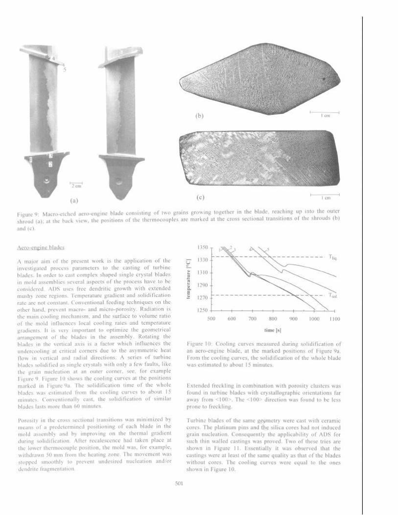
Figure 9: Macro-etched aero-engine blade consisting of two grains growing together in the blade, reaching up into the outer shroud (a); at the back view, the positions of the thermocouples are marked at the cross sectional transitions of the shrouds (b) and (c).
Aero-cnxine blades
A malor aim of the present work is the application of the investigated process parameters to the casting of turbine blades. In order to cast complex shaped single crystal blades in mold assemblies several aspects of the process have to be considered ADS uses free dendritic growth with extended mushy 7011~ regions ‘remperature gradient and solidification rate arc not constant. Conventional feeding techniques on the other hand. prevent macro- and micro-porosity. Radiation is the main cooling mechanism, and the surface to volume ratio of the mold Iniluenccs local cooling rates and temperature gradients. It is very important to optimize the geometrical arrangement of the blades in the assembly. Rotating the blades in the vertical axis is a factor which influences the undcrcooling at critical corners due to the asymmetric heat flow in vcrticnl and radial directions. A series of turbine blades solidified as single crystals with only a few faults, like the grain nucleation at an outer corner, see, for example Figure 9. ITlgure IO shows the cooling curves at the positions marked In Figure 9a. The solidification time of the whole blades was cstimatcd from the cooling curves to about I5 minutes. Conventionally cast, the solidification of similar blades lasts more than 60 minutes.
Porosity in the cross sectional transitions was minimized by means of a prcdctermined positioning of each blade in the mold assembly and by improving on the thermal gradient during solidilication. After recalescence had taken place at the lower thermocouple position, the mold was, for example, withdrawn 50 mm from the heating zone. The movement was stop@ smoothly to prevent undesired nucleation and/or dcndrltc fragmentation
500 600 700 800 900 1000 1100
time [s]
Figure 10: Cooling curves measured during solidification of an aero-engine blade, at the marked positions of Figure 9a. From the cooling curves, the solidification of the whole blade was estimated to about 15 minutes.
Extended freckling in combination with porosity clusters was found in turbine blades with crystallographic orientations far away from ~1001. The <loo> direction was found to be less prone to freckling.
Turbine blades of the same @ hetry t!
were cast with ceramic cores. The platinum pins and he silica cores had not induced grain nucleation. Consequently the applicability of ADS for such thin walled castings was proved. Two of these tries are shown in Figure 11. Essentially it was observed that the castings were at least of the same quality as that of the blades without cores. The cooling curves were equal to the ones shown in Figure 10.
501
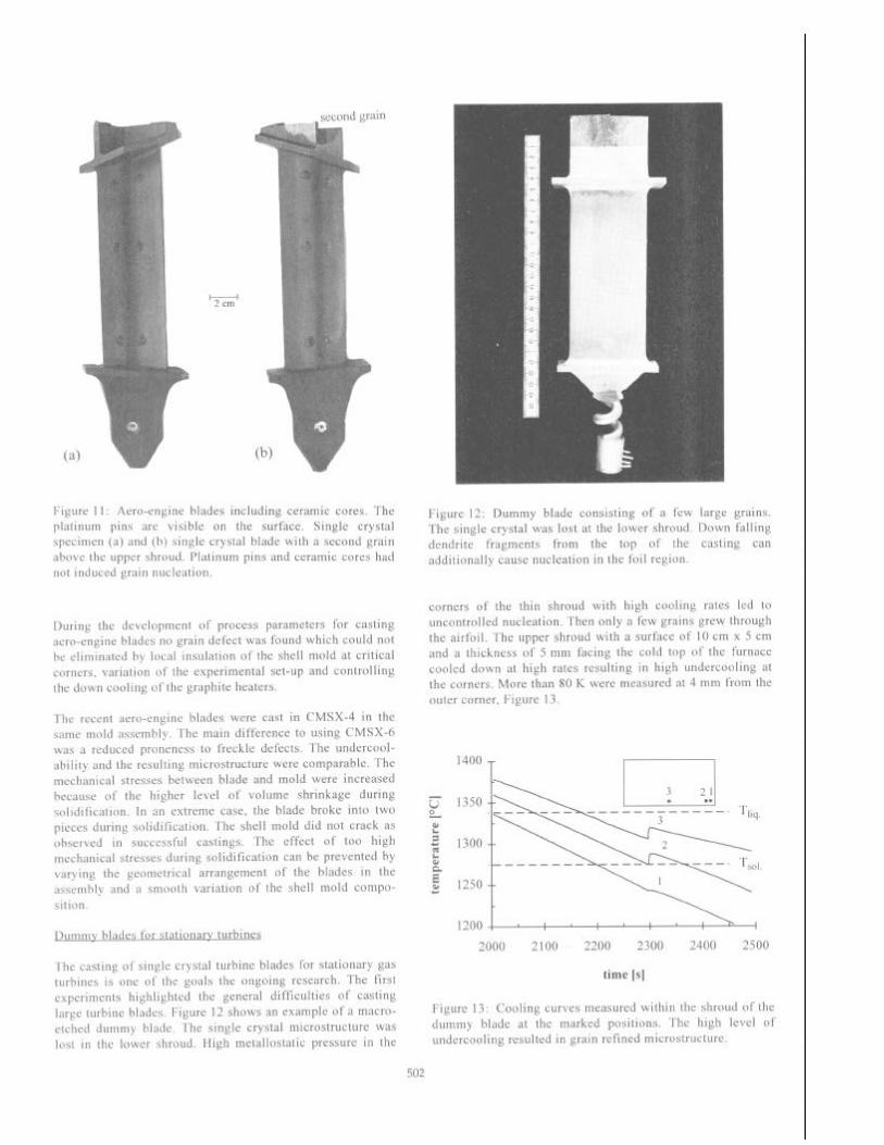
Figure 11: Aero-engine blades including ceramic cores. The platinum pins are visible on the surface. Single crystal specimen (a) and (b) single crystal blade with a second grain above the upper shroud. Platinum pins and ceramic cores had not induced grain nucleation.
During the development of process parameters for casting aero-engine blades no grain defect was found which could not be eliminated by local insulation of the shell mold at critical corners, variation of the experimental set-up and controlling the down cooling of the graphite heaters.
The recent aero-engine blades were cast in CMSX-4 in the same mold assembly. The main difference to using CMSX-6 was a reduced proneness to freckle defects. The undercool- ability and the resulting microstructure were comparable. The mechanical stresses between blade and mold were increased because of the higher level of volume shrinkage during solidification. In an extreme case, the blade broke into two pieces during solidification. The shell mold did not crack as observed in successful castings. The effect of too high mechanical stresses during solidification can be prevented by varying the geometrical arrangement of the blades in the assembly and a smooth variation of the shell mold compo- sition.
Dummv blades for stationary turbines
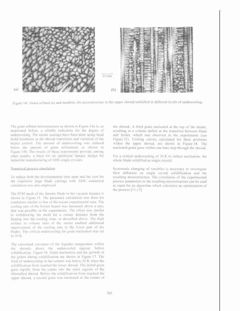
The casting of single crystal turbine blades for stationary gas turbines is one of the goals the ongoing research. The first experiments highlighted the general difficulties of casting large turbine blades. Figure 12 shows an example of a macro- etched dummy blade. The single crystal microstructure was lost in the lower shroud. High metallostatic pressure in the
Figure 12: Dummy blade consisting of a few large grains. The single crystal was lost at the lower shroud. Down falling dendrite fragments from the top of the casting can additionally cause nucleation in the foil region.
corners of the thin shroud with high cooling rates led to uncontrolled nucleation. Then only a few grains grew through the airfoil. The upper shroud with a surface of 10 cm x 5 cm and a thickness of 5 mm facing the cold top of the furnace cooled down at high rates resulting in high undercooling at the corners. More than 80 K were measured at 4 mm from the outer corner, Figure 13.
1400 T 1
1200:
2000 2100 2200 2300 2400 2500
time [s]
Figure 13: Cooling curves measured within the shroud of the dummy blade at the marked positions. The high level of undercooling resulted in grain refined microstructure.
502
(b)
The grain refined microstructure as shown in Figure 14a is, as mentioned before, a reliable indication for the degree of undercooling. The recent castings have been done using local mold insulation at the shroud transitions and variation of the heater control. The amount of undercooling was reduced below the amount of grain refinement. as shown in Figure 14b. The results of these experiments provide, among other results, a basis for an optimized furnace design for industrial manufacturing of ADS single crystals.
Numerical orocess simulation
To reduce both the developmental time span and the cost for the expensive large blade castings with ADS, numerical simulation was also employed.
The FEM mesh of the dummy blade in the vacuum furnace is shown in Figure 15. The presented calculation was done for conditions similar to that of the recent experimental runs. The cooling rate of the lowest heater was increased above a rate. that was possible in the experiments. The effect was similar to withdrawing the mold for a certain distance from the heating into the cooling zone, as described above. The high surface to volume ratio of the starter enabled additional improvement of the cooling rate in the lower part of the blades. The critical undercooling for grain nucleation was set to 20 K.
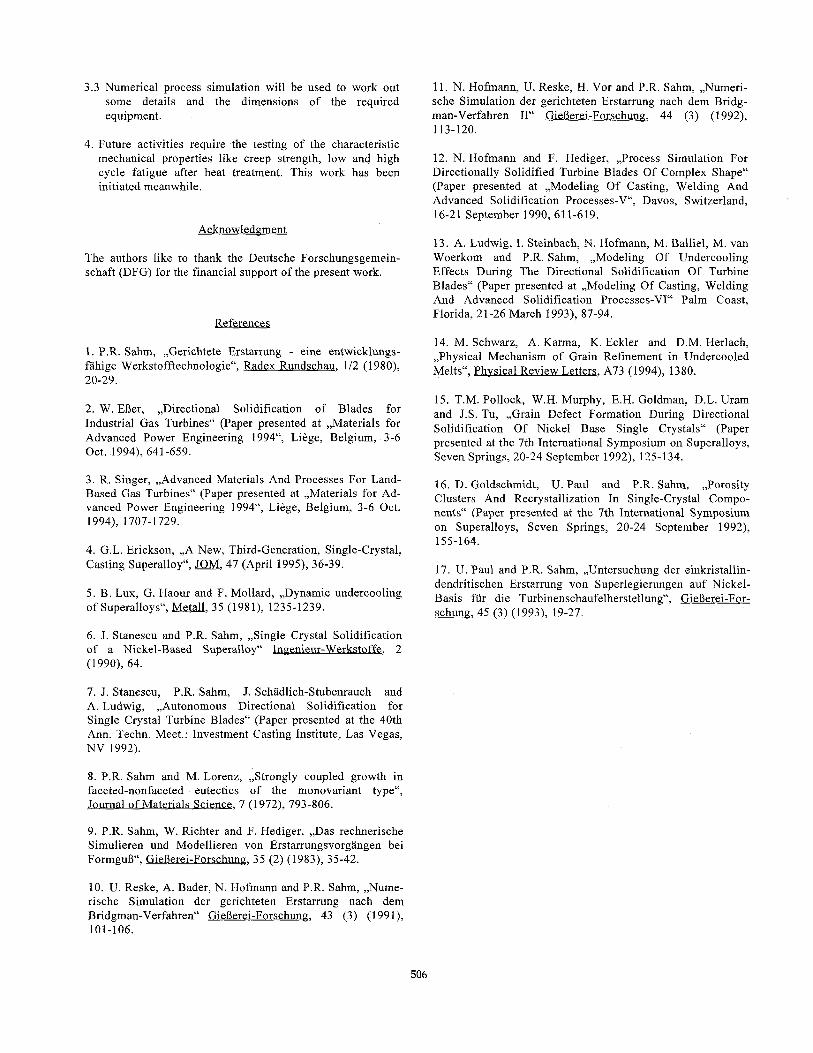
The calculated curvature of the liquidus temperature within the shrouds shows the undercooled regions before solidification. Figure 16. Grain nucleation and the growth of the grains during solidification are shown in Figure 17. The level of undercooling in the corners was below 20 K when the solidification front reached the lower shroud. The initial grain grew rapidly from the center into the outer regions of the thinwalled shroud. Before the solidification front reached the upper shroud, a second grain was nucleated in the corner of
the shroud. A third grain nucleated at the top of the feeder, resulting in a volume deficit at the transition between blade and feeder, which was observed in the experiments (see Figure 12). Cooling curves, calculated for three positions within the upper shroud, are shown in Figure 18. The nucleated grain grew within one time step through the shroud.
For a critical undercooling of 30 K to induce nucleation, the whole blade solidified as single crystal.
Systematic changing of variables is necessary to investigate their influence on single crystal solidification and the resulting microstructure. The correlation of the experimental process parameters to the resulting microstructure can be used as input for an algorithm which calculates an optimization of the process [11,13].
Figure 14: Grain refined (a) and dendritic (b) microstructure in the upper shroud solidified at different levels of undercooling.
503

Figure 15: FEM mesh of the experimental set-up for casting large turbine blades (a) and enlarged view of the dummy blade including starter and feeder (b).
sled
*cooled n
Figure 16: The curvature of the calculated liquidus isotherm at the lower (a) and the upper shroud (b) of the blade shows the undercooled regions.
504
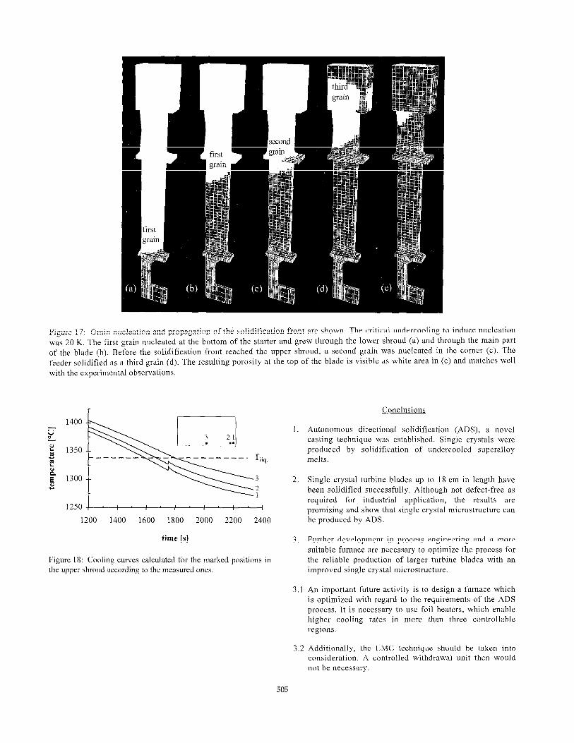
Figure 17: Grain nucleation and propagation of the solidification front are shown. The critical undercooling to induce nucleation was 20 K. The first grain nucleated at the bottom of the starter and grew through the lower shroud (a) and through the main part of the blade (b). Before the solidification front reached the upper shroud, a second grain was nucleated in the corner (c). The feeder solidified as a third grain (d). The resulting porosity at the top of the blade is visible as white area in (e) and matches well with the experimental observations.
1400
1 I::: &!&
1
1250 I
1200 1400 1600 1800 2000 2200 2400
time [s]
Figure 18: Cooling curves calculated for the marked positions in the upper shroud according to the measured ones.
Conclusions
1. Autonomous directional solidification (ADS), a novel casting technique was established. Single crystals were produced by solidification of undercooled superalloy melts.
2. Single crystal turbine blades up to 18 cm in length have been solidified successfully. Although not defect-free as required for industrial application, the results are promising and show that single crystal microstructure can be produced by ADS.
3. Further development in process engineering and a more suitable furnace are necessary to optimize the process for the reliable production of larger turbine blades with an improved single crystal microstructure.
3.1 An important future activity is to design a furnace which is optimized with regard to the requirements of the ADS process. It is necessary to use foil heaters, which enable higher cooling rates in more than three controllable regions.
3.2 Additionally, the LMC technique should be taken into
consideration. A controlled withdrawal unit then would not be necessary.
505
3.3 Numerical process simulation will be used to work out some details and the dimensions of the required equipment.
4. Future activities require the testing of the characteristic mechanical properties like creep strength, low and high cycle fatigue after heat treatment. This work has been initiated meanwhile.
Acknowledgment
The authors like to thank the Deutsche Forschungsgemein- schaft (DFG) for the financial support of the present work.
References
1. P.R. Sahm, ,,Gerichtete Erstarrung - eine entwicklungs- fahige Werkstofftechnologie“, Radex Rundschau, l/2 (1980), 20-29.
2. W. EDer, ,,Directional Solidification of Blades for Industrial Gas Turbines“ (Paper presented at ,,Materials for Advanced Power Engineering 1994“, Liege, Belgium, 3-6 Oct. 1994), 641-659.
3. R. Singer, ,,Advanced Materials And Processes For Land- Based Gas Turbines“ (Paper presented at ,,Materials for Ad- vanced Power Engineering 1994“, Liege, Belgium, 3-6 Oct. 1994), 1707-1729.
4. G.L. Erickson, ,,A New, Third-Generation, Single-Crystal, Casting Superalloy“, JOM, 47 (April 1995), 36-39.
5. B. Lux, G. Haour and F. Mollard, ,,Dynamic undercooling of Superalloys“, Metall, 35 (1981), 1235-1239.
6. J. Stanescu and P.R. Sahm, ,,Single Crystal Solidification of a Nickel-Based Superalloy“ Ingenieur-Werkstoffe, 2 (1990), 64.
7. J. Stanescu, P.R. Sahm, J. Schadlich-Stubenrauch and A. Ludwig, ,,Autonomous Directional Solidification for Single Crystal Turbine Blades“ (Paper presented at the 40th Ann. Techn. Meet.: Investment Casting Institute, Las Vegas, NV 1992).
8. P.R. Sahm and M. Lorenz , ,,Strongly coupled growth in faceted-nonfaceted eutectics of the monovariant type“, Journal of Materials Science, 7 (1972), 793806.
9. P.R. Sahm, W. Richter and F. Hediger, ,,Das rechnerische Simulieren und Modellieren von Erstarrungsvorgangen bei Formgug“, GieDerei-Forschung, 35 (2) (1983), 35-42.
10. U. Reske, A. Bader, N. Hofmann and P.R. Sahm, ,,Nume- rische Simulation der gerichteten Erstarrung nach dem Bridgman-Verfahren“ Gp, 43 (3) (1991), 101-106.
11. N. Hofmann, U. Reske, H. Vor and P.R. Sahm, ,,Numeri- sche Simulation der gerichteten Erstarrung nach dem Bridg- man-Verfahren II“ GieBerei-Forschung, 44 (3) (1992), 113-120.
12. N. Hofmann and F. Hediger, ,,Process Simulation For Directionally Solidified Turbine Blades Of Complex Shape“ (Paper presented at ,,Modeling Of Casting, Welding And Advanced Solidification Processes-V“, Davos, Switzerland, 16-21 September 1990, 611-619.
13. A. Ludwig, I. Steinbach, N. Hofmann, M. Balliel, M. van Woerkom and P.R. Sahm, ,,Modeling Of Undercooling Effects During The Directional Solidification Of Turbine Blades“ (Paper presented at ,,Modeling Of Casting, Welding And Advanced Solidification Processes-VI“ Palm Coast, Florida, 2 l-26 March 1993), 87-94.
14. M. Schwarz, A. Karma, K. Eckler and D.M. Herlach, ,,Physical Mechanism of Grain Refinement in Undercooled Melts“, Physical Review Letters, A73 (1994), 1380.
15. T.M. Pollock, W.H. Murphy, E.H. Goldman, D.L. Uram and J.S. Tu , ,,Grain Defect Formation During Directional Solidification Of Nickel Base Single Crystals“ (Paper presented at the 7th International Symposium on Superalloys, Seven Springs, 20-24 September 1992), 125-134.
16. D. Goldschmidt, U. Paul and P.R. Sahm, ,,Porosity Clusters And Recrystallization In Single-Crystal Compo- nents“ (Paper presented at the 7th International Symposium on Superalloys, Seven Springs, 20-24 September 1992), 155-164.
17. U. Paul and P.R. Sahm, ,,Untersuchung der einkristallin- dendritischen Erstarrung von Superlegierungen auf Nickel- Basis ftir die Turbinenschaufelherstellung“, GieRerei-For- schung, 45 (3) (1993), 19-27.
506