Automotive Telemetry System based on Controller Area · PDF fileAutomotive Telemetry System...
7
MMC 2013 CAN in Automation 06-14 Automotive Telemetry System based on Controller Area Network Y.A. Vershinin, M. Lorch (Coventry University) The Formula Student is a racing competition, where Students can apply their skills in a practical manner. To support their endeavors, the team asked for a Telemetry System, which is able to handle up to thirty sensors to monitor the cars performance on the racing track. A first Telemetry System was placed on the car, yet only supporting up to 12 sensors. To change that situation a project is issued to create a new Telemetry System based on CAN-Bus to replace the first one. The character of this project is to get familiar with the new technology. The next step will be either to enhance this system with more sensors, or to build again a completely new system based on the findingsobtained within this project. The basic architecture of the created system consists of three nodes: Node 1 is supposed to be placed in the front of the car to support five analogue sensors having the character of voltage dividers that were placed for the first system. Node 3 is supposed to be placed in the rear, supporting four thermocouples and two analogue sensors or voltage dividers. Node 2 is supposed to be placed in the middle of the car, where it receives the sensor values from nodes 1 and 3, assembles them into a string with specific format and prints it onto a RS-232 interface. From there on the data is transmitted via a RF-modem to a computer where it can be processed further. Each node consists out of the CAN enabled microcontroller PIC18F4580 to which the periphery is attached to. An In Circuit Serial Programming device is used to program the MCUs directly on the boards. The cornerstone of the communication design is the Remote Transmission Request feature, provided by the CAN protocol. It allows node 2 to request every single sensor value by putting a request frame onto the CAN. This means that this kind of communication can be scaled up easily from three nodes to a system with the same amount of nodes as there are sensors, in this case 12. Introduction Coventry University takes part in a competition called “Formula Student”, where students from all over the world are building their own racing car, and then meet to compete against each other on the racing track. In this way, the content of the lectures can be applied in a practical way. In the same time an invaluable contribution is added to their education. Despite the fun having experienced during the design, construction and later racing of such a car, the level of the work done is of the high quality and always a real achievement. Needless to say that strong competition drives the ambitions of the students. The increase of professionalism within the Formula Student raised the desire to improve the setup of the car by the implementation of an electronic system. In the future this shall allow monitoring the cars behavior on the racing track by several sensors, for example: temperature or a steering angle and recording the cars GPS-position including its current state of direction, velocity and acceleration. During later analysis it shall be possible to replay the laps on the PC. The evelopment of the system is done by students within their final year- or MSc- projects. Unfortunately the scale of the final system is way too large for one single student. Therefore the whole development process is split into iterations, where each iteration is equivalent to one student’s project.
-
Upload
trinhhuong -
Category
Documents
-
view
228 -
download
3
Transcript of Automotive Telemetry System based on Controller Area · PDF fileAutomotive Telemetry System...
MMC 2013 CAN in Automation
06-14
Automotive Telemetry System based on Controller Area Network
Y.A. Vershinin, M. Lorch (Coventry University)
The Formula Student is a racing competition, where Students can apply their skills in a practical manner. To support their endeavors, the team asked for a Telemetry System, which is able to handle up to thirty sensors to monitor the cars performance on the racing track. A first Telemetry System was placed on the car, yet only supporting up to 12 sensors. To change that situation a project is issued to create a new Telemetry System based on CAN-Bus to replace the first one. The character of this project is to get familiar with the new technology. The next step will be either to enhance this system with more sensors, or to build again a completely new system based on the findingsobtained within this project. The basic architecture of the created system consists of three nodes: Node 1 is supposed to be placed in the front of the car to support five analogue sensors having the character of voltage dividers that were placed for the first system. Node 3 is supposed to be placed in the rear, supporting four thermocouples and two analogue sensors or voltage dividers. Node 2 is supposed to be placed in the middle of the car, where it receives the sensor values from nodes 1 and 3, assembles them into a string with specific format and prints it onto a RS-232 interface. From there on the data is transmitted via a RF-modem to a computer where it can be processed further. Each node consists out of the CAN enabled microcontroller PIC18F4580 to which the periphery is attached to. An In Circuit Serial Programming device is used to program the MCUs directly on the boards. The cornerstone of the communication design is the Remote Transmission Request feature, provided by the CAN protocol. It allows node 2 to request every single sensor value by putting a request frame onto the CAN. This means that this kind of communication can be scaled up easily from three nodes to a system with the same amount of nodes as there are sensors, in this case 12.
Introduction Coventry University takes part in a competition called “Formula Student”, where students from all over the world are building their own racing car, and then meet to compete against each other on the racing track. In this way, the content of the lectures can be applied in a practical way. In the same time an invaluable contribution is added to their education. Despite the fun having experienced during the design, construction and later racing of such a car, the level of the work done is of the high quality and always a real achievement. Needless to say that strong competition drives the ambitions of the students. The increase of professionalism within the Formula Student raised the desire to improve the setup of the car by the implementation of an electronic system. In the future this shall allow monitoring the cars behavior on the racing track by several sensors, for example: temperature or a steering angle and recording the cars GPS-position including its current state of direction, velocity and acceleration. During later analysis it shall be possible to replay the laps on the PC. The evelopment of the system is done by students within their final year- or MSc- projects. Unfortunately the scale of the final system is way too large for one single student. Therefore the whole development process is split into iterations, where each iteration is equivalent to one student’s project.
MMC 2013 CAN in Automation
06-15
This paper is about the second iteration where a Telemetry system based on CAN-Bus technology has to be developed. With the use of CAN, the foundation is laid for further extensions of the system rather than always creating a new system from scratch. Using the environment of the previous system within this project by means of having the same sensors and applying the same way of transmitting sensor data to a computer allows one to concentrate on the CAN-Bus technology itself. The first telemetry system, based on a PIC18F452 microcontroller This chapter shall give a brief overview of the previous telemetry system (Fig.1), as it provides the environment, into which the new system has to fit in. Basic working principle: 1) The system starts working with power
up; 2) The microcontroller polls through all
rotational and longitudinal sensors and assembles all their values to one string;
3) The string is sent to an RF-modem using the RS-232 standard and is streamed into a PC, where a small VBA-program displays the current sensor values, (Fig. 2 Screenshot of the program processing the data from the telemetry system);
4) After sending the string, the microcontroller polls through all thermocouples and assembles a string with temperature values;
5) The string is sent to the RS-232 interface;
6) The whole process continues until power down of the system.
The continuous stream of data strings causes the information on PC side being constantly updated. Architecture The project, dealing with a Telemetry System in the first place had its main concern in creating a working system from total scratch. Various problems in different
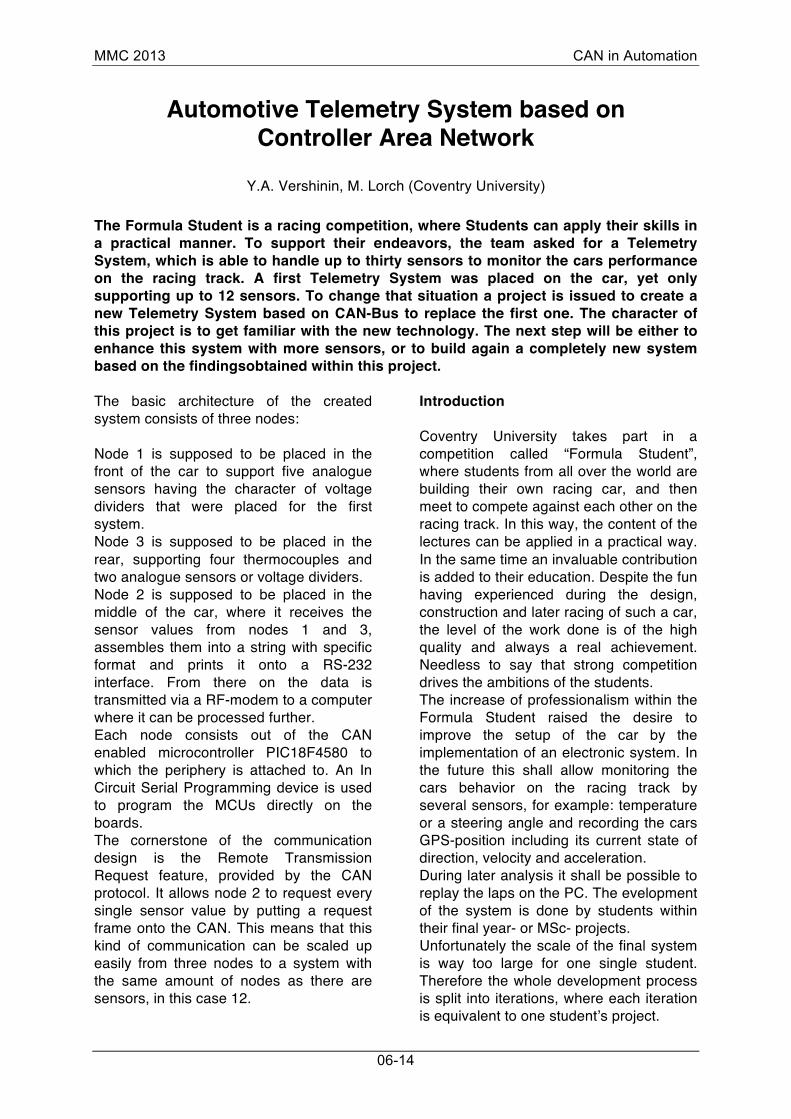
areas had to be solved within a projects time; hence the system itself has a very simple architecture. Its core consists out of a single microcontroller of type PIC18F452. This system supports up to seven analogue inputs. Furthermore the system supports four thermocouples; each being connected to a thermocouple-to-digital converter, in this case an IC of type MAX6675. These ICs are connected to the microcontroller over the SPIinterface, with each IC occupying one digital input of the MCU, linking the pins for the cable select (CS) of the SPI- interface. The data output of the system is done by the MAX232 RS-232 Interface IC, allowing to stream the sensor data over the serial connection into the PC. Figure 1 shows the system board with some attached sensors, which are used in the car together with a small panel of potentiometers for testing purposes.
Figure 1: The first telemetry system Attached sensors The system is designed to pick up the movements of the dampers, the breaking and throttle-pedal and the angle of the steering wheel. To do that, sensors from the company Penny+Giles are fitted to the car. The sensors have the same electrical characteristic as normal potentiometers, thus no matter of their mechanical design – linear or rotational – they are used as voltage dividers. The electrical output of these sensors by means of a variable voltage between 0 V and 5 V is directly
MMC 2013 CAN in Automation
06-16
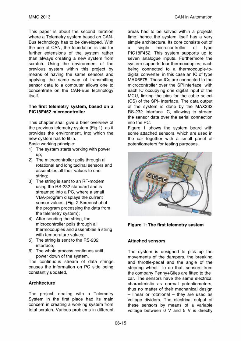
applied to an analogue input of the microcontroller. An internal A/D converter changes the input voltage into a numerical value within the range of 0 - 255. The system’s second task is to monitor temperatures of gases from four exhaust pipes of a car’s engine. To do so, four thermocouples of K-type are used in conjunction with ICs of type MAX6675. These chips deliver a 16-bit number representing the temperature value over the SPI- interface directly into the microcontroller. Data string assembly and data transmission to the PC As described before, two different strings are assembled, i.e. one for the analogue sensor data and one for the thermocouple data. The sensor information is assembled to one string with characteristic start-, split- and end-characters, allowing the software on the PC to identify the single values, (Fig. 2 Screenshot of the program processing the data from the telemetry system). The continuous transmission of new strings at time intervals of approximately 35 ms ensures a smooth data update on the PC-side. The time interval of 35 ms is determined by the maximum bandwidth of 9600 Baud of the used RF-modem. The software on the PC-side is an application written in Visual Basic. It receives the value from the RS-232 interface and displays the new data in the graphs. It is not described, which value is representing which sensor on the car. This is due to the fact, that depending on the desired data, the plugged sensors are altered during the use. With all analogue sensors delivering 8-bit data and all thermocouples delivering 16-bit data, the format of information always stays the same and therefore positions can be shuffled as required.
Figure 2: Screenshot of the program processing the data from the telemetry system Advantages and disadvantages Advantages: Due to the simple architecture, the system is very robust and easy to handle. Problems can be found easily. Furthermore, through direct connection of the sensors to the microcontroller, the system is able to assemble the output strings very quickly. By an increase of the available bandwidth of the RFmodem, the amount of transmitted data to the PC could be increased even more. The concept of the system is very straight forward. With that, even a person with no skills in electronics could be able to understand it within a fair amount of time. Disadvantages: The downside of the system clearly lies in its conceptual exhaustion. Considering, that the used microcontroller provides a total amount of eight analogue inputs, which can be used for A/D conversion and seven of them already being used, the system is exhausted from the start. The system could be scaled up by the use of a multiplexer, but due to its star-topology, this would highly increase wiring harnesses and therefore confusion in the car. Introduction to CAN-Bus technology in conjunction with the PIC18F4580 MCU The CAN-Bus is a field bus-technology initially being developed for the automotive industry sector by BOSCH [1] from the
MMC 2013 CAN in Automation
06-17
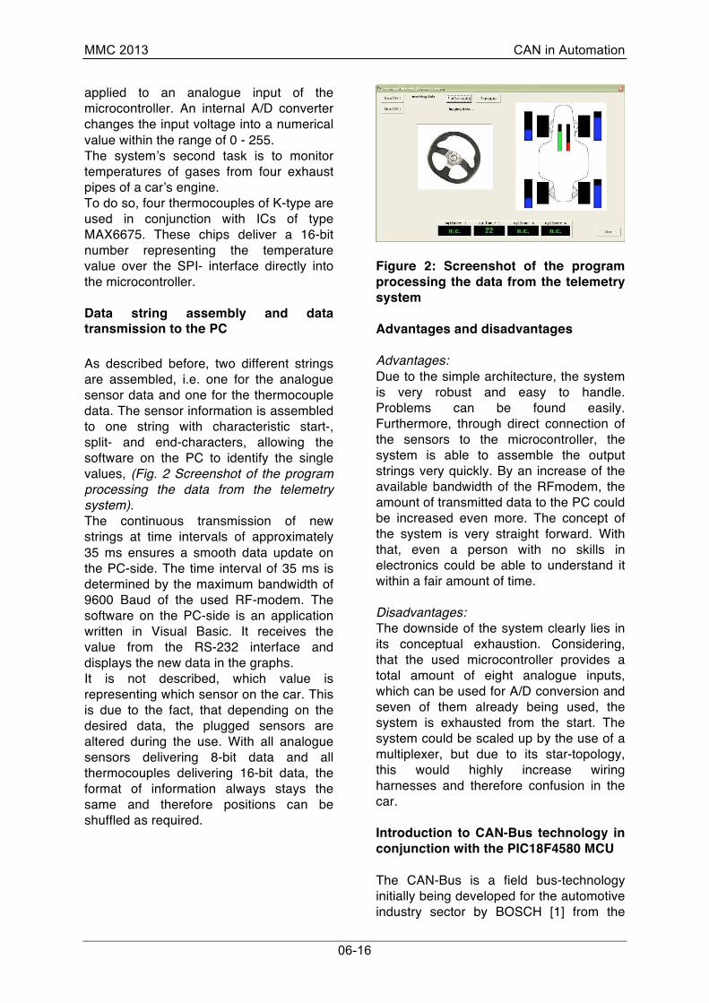
1980’s on. The aim was to reduce complexity in wiring between systems, sensors and actuators placed in a car and therefore to reduce costs and increase maintainability and reliability [2]. For the use in an automotive environment, requirements were defined and later on realized in the CAN-protocol. Today CAN is a widely spread technology that is not restricted to the automotive industry, it found large applications e.g. in the automation industry [3]. Auto-Remote Transmission-Request (Auto-RTR) The usual CAN-communication is done by nodes sending data if information is generated. The CANprotocol also allows triggering communication the other way round: a node can request information from another node through sending a “remote request frame”. This is a frame with the RTR-flag set and an ID, to which a node in the network is programmed to react to. The replying node will send a frame with the content requested and the same ID as the request-frame itself, (Fig. 3 Auto Remote Transmission Request in a UML sequence diagram).
Figure 3: Auto Remote Transmission Request in a UML sequence diagram PIC18F4580: CAN-functionality within the internal CAN-controller The choice for a specific microcontroller within the PIC-family is done for the PIC18F4580 for several reasons: 1) The particular device is a CAN-enabled
microcontroller, meaning the board layout is tremendously simplified compared to a PCB for a micro-controller with external CANcontroller;
2) The use of a non-CAN-enabled MCU together with a separate CAN- Controller has no advantage compared to the already CAN-enabled MCU;
3) Supporting a clock frequency of up to 40 MHz, the microcontroller is that powerful to provide enough spares if it is needed.
The new telemetry system, based on CAN The new system has to fit perfectly into the old environment by means of amount of sensors, a used radio transmitter modem and software on PC-side. These conditions together with the tight time scale already restrict a large part of the new system by means of numbers and complexity of PCBs. A system meeting all these constraints is presented below. The decision making process There is a wide range of how such system can be implemented. To narrow down these possibilities, the following procedure is used: The decision about the architecture of the new system is done by listing the wanted properties, the general possibilities of creating such systems and the outer conditions, limiting the available possibilities. These are basically all the properties of the old system together with added expandability due to the implementation of CAN, i.e.: 1) Fitting perfectly into the old
environment provided by the first telemetry system;
2) Creating the data update on PC-side as quickly as the old system;
3) Being able to add more sensors, which can be used in further iteration steps;
4) Easy to use and understand; 5) Meeting the requirements of a racing
car in terms of weight and size.
MMC 2013 CAN in Automation
06-18
Considered possibilities of creating such systems A short list of different possibilities is considered. This listing does not raise the claim of completeness: 1) Creating the CAN-interfaces based on
one MCU; 2) Creating a mix out of several interfaces
with various MCUs; 3) Using a single CAN-interface to each
sensor; 4) Combining several sensors to one
CAN-interface; 5) Using industrial sensors that already
provide a CAN-interface. 4.3 Amount and position of nodes Looking at the position of sensors within the car, it can be noticed that two separate areas can be used, where sensors are located. Within these areas, cable lengths of less than 50 cm are sufficient to connect all these sensors to one node, making two nodes unjustifiable; especially because of the lack of the available space. The first area is in the front of the car with two linear damper potentiometers, two pedal potentiometers and a potentiometer for the steering wheel. Secondly, in the rear part of the car two linear damper potentiometers and four thermocouples for the engine are installed. A separate node can be installed in each of these areas. Thus, it has been decided to use three nodes on a car. In this case two nodes will communicate with each other and the third node will act as a disturbing node. Therefore, the third node is responsible for the receiving the sensors information from the front node and f rom th e rear node. Also, the third node provides the assembling of strings, which are sent to the RF-modem. Provided interfaces on each node In the basic system’s architecture (which consists of three nodes) the required interfaces for each node are: 1) the CAN interface; 2) the RS-232 interface for the middle node 2;
3) five analogue sensors connections for the front node 1;
4) two analogue sensors connections and four thermocouples connections for the rear node 3.
With this design, it is possible to create a system which will meet the requirements given above. The Board-1 node is located in the front of the car and is responsible for the retrieving values from five analogue sensors. The Board-2 node receives all sensors data from the other two nodes and assembles the output strings. This node contains the MAX232-chip (from Texas Instruments), which allows one to open the serial communication according to the RS-232 protocol. This is used in order to connect the radio transmitter modem, to send the sensor’s data to the PC in the pit. The Board-3 node: due to the fact that this node is responsible for the retrieving of temperature values from thermocouples, it is the most complex one as every thermocouple needs to have its own MAX6675 ICs. These ICs chips (for the reading the data from thermocouples) were placed on a small separate board, which was designed for the first telemetry system. Therefore, the Board 3 could be kept simple. Only a 10 way-IDC-plug is fitted to this board in order to connect it with the small separate board, which contains MAX6675 ICs. The output of the system to the RF-modem has to be either a string containing all analogue sensor data or a string containing all thermocouple data. With that no sensor value has got any priority to the others, as all of them are needed at the same time. The complete system – Ready for use At the end of the project, all boards were put into rugged aluminum boxes. Waterproof Sub-D 9 way plugs panel mount are attached in order to connect the boards in between. Node 1 has a waterproof 17 way plug panel mount in order to connect the frontal sensors.
MMC 2013 CAN in Automation
06-19
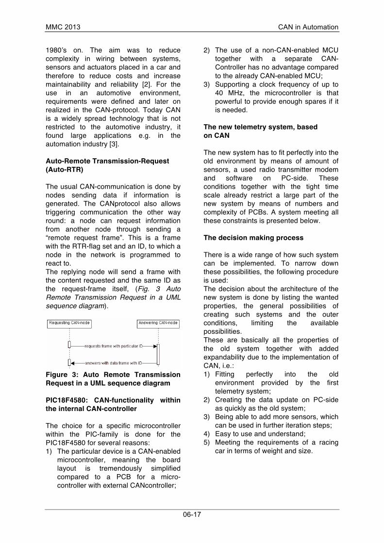
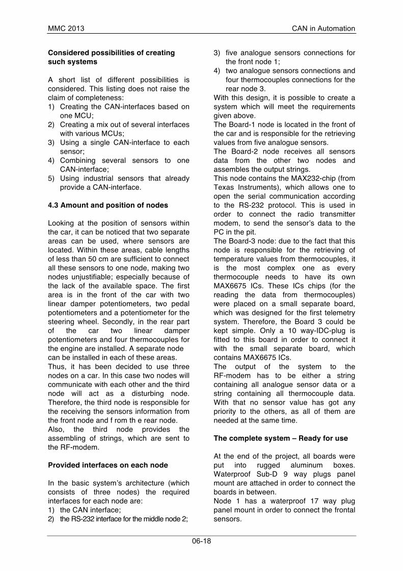
Node 2 has a waterproof 4 way plug in order to connect to a battery with +12 V. Furthermore, a Sub-D 9 way socket is attached for the connection to the RF-modem or PC respectively. Node 3 has a waterproof 9 way plug panel mount in order to connect two rear damper potentiometers. Thermocouple sockets are also provided on the node.
Figure 4: The complete system including wiring and terminators Shielding and wiring between nodes and boards The three nodes are connected to each other by the S/UTP-cable with 9 way SUB-D- plugs. This particular cable is chosen since the area surrounding the engine is expected to be very noisy. The ignition system very likely can cause Electromagnetic Pulses (EMP) [4], which can interfere with the high frequency communication on the CAN-Bus itself and can restrain the communication or even prevent the CAN-Bus from the working at all. A metallic casing for the nodes is chosen for the same reason as such would form a faraday cage [5] around the PCBs of the nodes. To complete the CAN wiring, terminators are plugged to the non-used CAN sockets outside the boxes. These terminators contain 120 Ohm resistors in order to protect the CAN-Bus from the signal’s reflection on the open ends.
Discussion and Conclusions The main concern coming up when applying a field bus to an existing system is that the amount of information being created with an old system does not exceed the capabilities of the chosen field bus. Due to the fact that the RS-232 interface ( via which the information finally has to go through) has a far less bandwidth, this concern does not apply in the first place. The question is though, that the communication can be programmed in such a way, that the same speed can be expected in terms of t he reaction and resolution as it was shown from the old system. It can be concluded that this aim has been achieved. The new system mainly meets the requirements stated in “The desired properties of the new system”. It is able to do the same job as the previous system, but delivers the important property of the expandability. Based on these results, it should be very easy to enhance it with a new node; for example, - to connect additional thermocouples or other required sensors.
MMC 2013 CAN in Automation
06-20
Y. A. Vershinin Coventry University Priory Street GB-CV1 5FB Coventry +44 (0) 24 7688 7688 www.coventry.ac.uk
M. Lorch Coventry University Priory Street GB-CV1 5FB Coventry +44 (0) 24 7688 7688 www.coventry.ac.uk References [1] http://www.semiconductors.bosch.de/en/
20/can/index.asp [2] BOSCH (2004) “BOSCH Handbook”, 6th
edition. [3] Wolfhard Lawrenz (1997) “CAN System
Engineering, From Theory to Practical Applications”.
[4] http://en.wikipedia.org/wiki/ Electromagnetic_pulse. [5] http://en.wikipedia.org/wiki/Faraday_cage.