AUTOMOTIVE INDUSTRY STANDARD - ARAI India · Draft AIS-137 (PART-5)/D0 December 2016. DRAFT ....
63
Draft AIS-137 (PART-5)/D0 December 2016 DRAFT AUTOMOTIVE INDUSTRY STANDARD Document on Test Method, Testing Equipment and Related Procedures for Testing Type Approval and Conformity of Production (COP) of Vehicles for Emission as per CMV Rules 115, 116 and 126 ARAI Date of hosting on website: 12 th December 2016 Last date for comments: 11 th January 2017
Transcript of AUTOMOTIVE INDUSTRY STANDARD - ARAI India · Draft AIS-137 (PART-5)/D0 December 2016. DRAFT ....

Draft AIS-137 (PART-5)/D0 December 2016
DRAFT
AUTOMOTIVE INDUSTRY STANDARD
Document on Test Method,
Testing Equipment and Related
Procedures for
Testing Type Approval and Conformity
of Production (COP) of Vehicles for
Emission as per CMV Rules 115, 116
and 126
ARAI
Date of hosting on website: 12th December 2016 Last date for comments: 11th January 2017
Draft AIS-137 (PART-5)/D0 December 2016
Status chart of the Standard to be used by the purchaser for updating the record
Sr.
No.
Corrige-
nda.
Amend-
ment
Revision Date Remark Misc.
General Remarks:

Draft AIS-137 (PART-5)/D0 December 2016
INTRODUCTION
The Government of India felt the need for a permanent agency to expedite the Publication of standards and development of test facilities in parallel when the work on the preparation of the standards is going on, as the development of improved safety critical parts can be undertaken only after the publication of the standard and commissioning of test facilities. To this end, the erstwhile Ministry of Surface Transport (MoST) has constituted a permanent Automotive Industry Standards Committee (AISC) vide order No. RT-11028/11/97-MVL dated September 15, 1997. The standards prepared by AISC will be approved by the permanent CMVR Technical Standing Committee (CTSC). After approval, the Automotive Research Association of India, (ARAI), Pune, being the secretariat of the AIS Committee, has published this standard.
(Panel convenor may include introductory paragraph regarding background of
the standard. He may include following points):
1. Need & Justification
2. India’s specific requirements (if any)
3. Enhancement of safety.
4. Any other point.
While preparing this standard, considerable assistance has been taken from Following:
(List of ECE regulations / EEC Directives / Global Technical Regulations
(GTRs)/ other National and International Standards etc. may be provided)
1. ECE regulations
2. EEC Directives
• The AISC panel responsible for formulation of this standard is given in Annex: (To be included)
• The Automotive Industry Standards Committee (AISC) responsible for approval of this standard is given in Annex: (To be included)
Draft AIS-137 (PART-5)/D0 December 2016
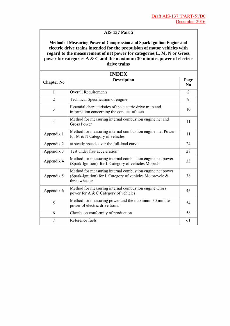
AIS 137 Part 5
Method of Measuring Power of Compression and Spark Ignition Engine and
electric drive trains intended for the propulsion of motor vehicles with
regard to the measurement of net power for categories L, M, N or Gross
power for categories A & C and the maximum 30 minutes power of electric
drive trains
INDEX
Chapter No Description Page
No
1 Overall Requirements 2
2 Technical Specification of engine 9
3 Essential characteristics of the electric drive train and information concerning the conduct of tests 10
4 Method for measuring internal combustion engine net and Gross Power 11
Appendix 1 Method for measuring internal combustion engine net Power for M & N Category of vehicles 11
Appendix 2 at steady speeds over the full-load curve 24
Appendix 3 Test under free acceleration 28
Appendix 4 Method for measuring internal combustion engine net power (Spark-Ignition) for L Category of vehicles Mopeds 33
Appendix 5 Method for measuring internal combustion engine net power (Spark-Ignition) for L Category of vehicles Motorcycle & three wheeler
38
Appendix 6 Method for measuring internal combustion engine Gross power for A & C Category of vehicles 45
5 Method for measuring power and the maximum 30 minutes power of electric drive trains 54
6 Checks on conformity of production 58
7 Reference fuels 61

Draft AIS-137 (PART-5)/D0 December 2016
CHAPTER 1
Overall Requirements
1. Scope
1.1 This Chapter applies to the representation of the curve as a function of engine or motor speed of the power at full load indicated by the manufacturer for internal combustion engines or electric drive trains and the maximum 30 minutes power of electric drive trains intended for the propulsion of motor vehicles of categories M and N1.
1.2 The internal combustion engines belong to one of the following categories: Reciprocating piston engines (positive-ignition or compression-ignition), but excluding free piston engines; Rotary piston engines (positive-ignition or compression ignition); Naturally aspirated or supercharged engines.
1.3 The electric drive trains are composed of controllers and motors and are used for propulsion of vehicles as the sole mode of propulsion.
1.4 This chapter also covers the measurement of Opacity (smoke) of the Exhaust gas of compression ignition engines.
2. Definitions
2.1 "Approval of a drive train" means the approval of a drive train type with regard to its net power measured in accordance with the procedure specified in Chapter 4 or 5 to this AIS 137,Part 5.
2.2 "Drive train type" means a category of an internal combustion engine or an electric drive train for installation in a motor vehicle which does not differ in such essential characteristics as those defined in chapter 4 or 5 to this part 5.
2.3 "Net power" means the power obtained on a test bench at the end of the crankshaft or its equivalent (If power measurement can be carried out only on an engine with the gear box mounted, the efficiency of the gear-box shall be taken into account)at the corresponding engine or motor speed with the auxiliaries listed in Table 1 of chapter 4 or in chapter 5 to this part5, and determined under reference atmospheric condition;
2.4 "Maximum net power" means the maximum value of the net power measured at full engine load;
Draft AIS-137 (PART-5)/D0 December 2016
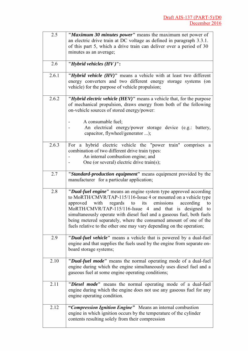
2.5 "Maximum 30 minutes power" means the maximum net power of an electric drive train at DC voltage as defined in paragraph 3.3.1. of this part 5, which a drive train can deliver over a period of 30 minutes as an average;
2.6 "Hybrid vehicles (HV )":
2.6.1 "Hybrid vehicle (HV)" means a vehicle with at least two different
energy converters and two different energy storage systems (on vehicle) for the purpose of vehicle propulsion;
2.6.2 "Hybrid electric vehicle (HEV)" means a vehicle that, for the purpose of mechanical propulsion, draws energy from both of the following on-vehicle sources of stored energy/power: - A consumable fuel; - An electrical energy/power storage device (e.g.: battery,
capacitor, flywheel/generator ...);
2.6.3 For a hybrid electric vehicle the "power train" comprises a combination of two different drive train types: - An internal combustion engine; and - One (or several) electric drive train(s);
2.7 "Standard-production equipment" means equipment provided by the manufacturer for a particular application;
2.8 "Dual-fuel engine" means an engine system type approved according to MoRTH/CMVR/TAP-115/116-Issue 4 or mounted on a vehicle type approved with regards to its emissions according to MoRTH/CMVR/TAP-115/116-Issue 4 and that is designed to simultaneously operate with diesel fuel and a gaseous fuel, both fuels being metered separately, where the consumed amount of one of the fuels relative to the other one may vary depending on the operation;
2.9 "Dual-fuel vehicle" means a vehicle that is powered by a dual-fuel engine and that supplies the fuels used by the engine from separate on-board storage systems;
2.10 "Dual-fuel mode" means the normal operating mode of a dual-fuel engine during which the engine simultaneously uses diesel fuel and a gaseous fuel at some engine operating conditions;
2.11 "Diesel mode" means the normal operating mode of a dual-fuel engine during which the engine does not use any gaseous fuel for any engine operating condition.
2.12 “Compression Ignition Engine” Means an internal combustion engine in which ignition occurs by the temperature of the cylinder contents resulting solely from their compression

Draft AIS-137 (PART-5)/D0 December 2016
2.13 “Positive Ignition Engine” Means an internal combustion engine in which the combustion of the air/fuel mixture is initiated at given instant by a hot spot, usually an electric spark
2.14 “Engine Speed” The number of revolutions of crankshaft in a given period of time.
2.15 “Engine Torque” Means torque measured at the end of the crankshaft or its equivalent (if power measurement can be carried out only on an engine with the gear-box mounted as declared by the manufacturer, the efficiency of the gear-box shall be taken into account) at the corresponding engine speed with the auxiliaries listed in Table 1, and determined under reference atmospheric conditions.
2.16 “Specific Fuel Consumption” The quantity of fuel consumed by the engine Expressed in g/kWh
2.17 “Intake Air Depression” The mean pressure head below atmospheric (suction) pressure existing in the intake manifold with an air cleaner fitted expressed in kPa.
2.18 “Exhaust Back Pressure” The mean static pressure head existing in the exhaust pipe of an engine test bed installation measured at a point m the pipe 150 mm downstream from the outlet flange of the engine manifold/turbo charge outlet expressed in kPa.
2.19 “Lubricating Oil Pressure” Oil pressure at given points of the lubricating system (in individual circuits before and after filters, coolers, etc).
2.20 “Air Intake Temperature” The temperature expressed in Keivin (K) measured with in 150 mm of the air falter.
2.21 “Exhaust Gas Temperature” Temperature of the exhaust gas measured at a point in the exhaust pipe 150 mm downstream from the outlet flange of the exhaust manifold or 150 mm from the outlet flange of the turbo charger expressed in Kelvin (K).
2.22 “Coolant Temperature” Temperature(s) at given point(s) such as after the thermostat or of the fluid cooling system(s) expressed fin Kelvin (K).
2.23 “Lubricating Oil Temperature” Oil temperature(s) at given point(s) of the lubricating system(s) expressed in Kelvin (K).
2.24 “Fuel Temperature”
a) In cast of spark ignition engines the fuel temperature shall be measured as near as possible to the inlet of the carburetor or fuel injection assembly. Means either the highest of the following three engine.

Draft AIS-137 (PART-5)/D0 December 2016
b) In case of compression ignition engines, the fuel temperature shall be measured at the inlet to the injection pump. At the request of the manufacturer the fuel temperature measurement can be made at another point in the pump representative off the engine operating condition.
2.25 “Smoke Density” Means the light absorption coefficient of the exhaust gases emitted by the vehicle expressed in terms of m-l or in other units such as Hartridge, percent opacity
2.26 “Light Absorption Coefficient” Means the percentage of light absorption in one meter length of measurement tube of the smoke meter.
2.27 “Opacity Meter” Means an instrument for continuous measurement of the light absorption coefficient of the exhaust gases emitted by automotive vehicles
2.28 Maximum Rated Speed: Means the maximum speed permitted by governor at full load, unless otherwise declared by the manufacturer.
2.29 Minimum Rated Speed: Means either the highest of the following three engine speeds:
- 45 percent of maximum net power speed,
- (55 percent of maximum net power speed for A & C
Category of vehicles) - 1 000 rev/min,
- minimum speed permitted by the idling control, Or such lower speed as the manufacturer may specify
2.30 Cold Start Device: Means a device which enriches the fuel-air mixture of the engine temporarily and thus assist in engine start up.
2.31 Starting Aid: Means a device which assists the engine start up without enrichment of the fuel~mixture such as glow plug, change of injection timing.
2.32 "Approval of an engine family" means the approval of the members of an engine family with regard to their net power.
2.33 "Engine family" means a manufacturer's grouping of engines which, through their design, fulfil the grouping criteria laid down in family Annexure
2.34 "Parent engine" means an engine selected from an engine family in such a way that it complies with requirements set out in family Annexure.
2.35 "Rated net power" means engine net power as declared by the manufacturer at rated speed.
Draft AIS-137 (PART-5)/D0 December 2016
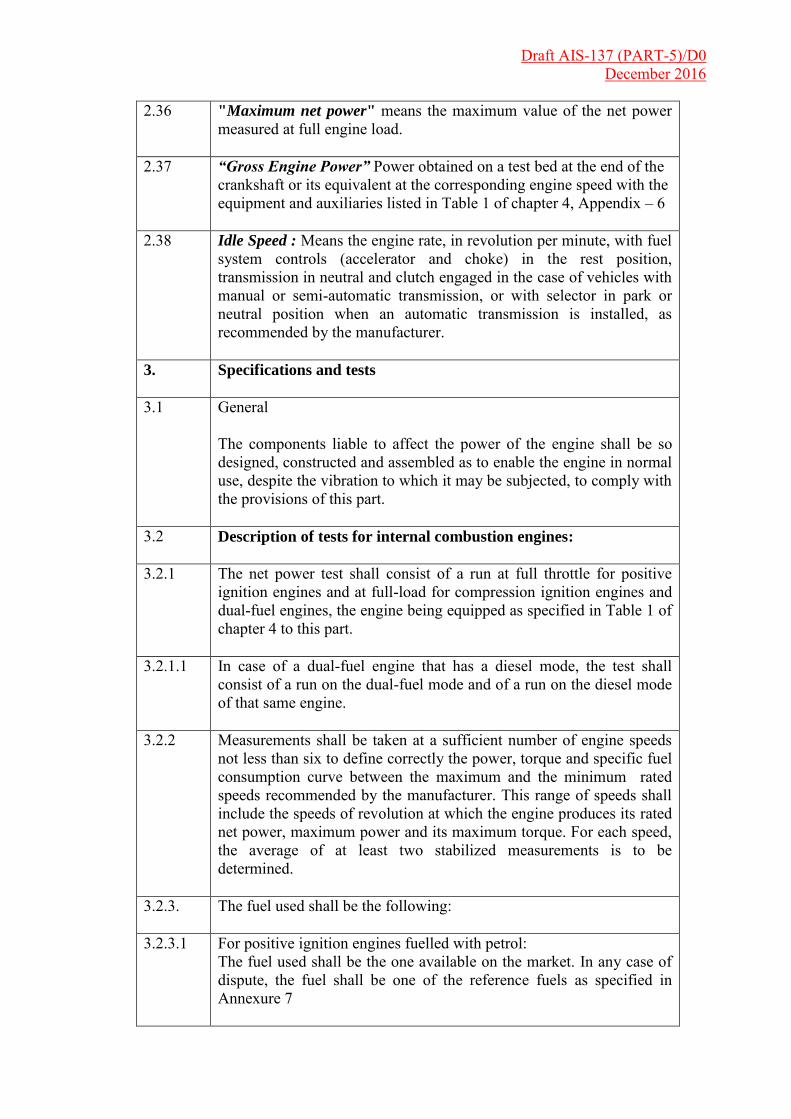
2.36 "Maximum net power" means the maximum value of the net power measured at full engine load.
2.37 “Gross Engine Power” Power obtained on a test bed at the end of the crankshaft or its equivalent at the corresponding engine speed with the equipment and auxiliaries listed in Table 1 of chapter 4, Appendix – 6
2.38 Idle Speed : Means the engine rate, in revolution per minute, with fuel system controls (accelerator and choke) in the rest position, transmission in neutral and clutch engaged in the case of vehicles with manual or semi-automatic transmission, or with selector in park or neutral position when an automatic transmission is installed, as recommended by the manufacturer.
3. Specifications and tests
3.1 General The components liable to affect the power of the engine shall be so designed, constructed and assembled as to enable the engine in normal use, despite the vibration to which it may be subjected, to comply with the provisions of this part.
3.2 Description of tests for internal combustion engines:
3.2.1 The net power test shall consist of a run at full throttle for positive
ignition engines and at full-load for compression ignition engines and dual-fuel engines, the engine being equipped as specified in Table 1 of chapter 4 to this part.
3.2.1.1 In case of a dual-fuel engine that has a diesel mode, the test shall consist of a run on the dual-fuel mode and of a run on the diesel mode of that same engine.
3.2.2 Measurements shall be taken at a sufficient number of engine speeds not less than six to define correctly the power, torque and specific fuel consumption curve between the maximum and the minimum rated speeds recommended by the manufacturer. This range of speeds shall include the speeds of revolution at which the engine produces its rated net power, maximum power and its maximum torque. For each speed, the average of at least two stabilized measurements is to be determined.
3.2.3. The fuel used shall be the following:
3.2.3.1 For positive ignition engines fuelled with petrol: The fuel used shall be the one available on the market. In any case of dispute, the fuel shall be one of the reference fuels as specified in Annexure 7
Draft AIS-137 (PART-5)/D0 December 2016
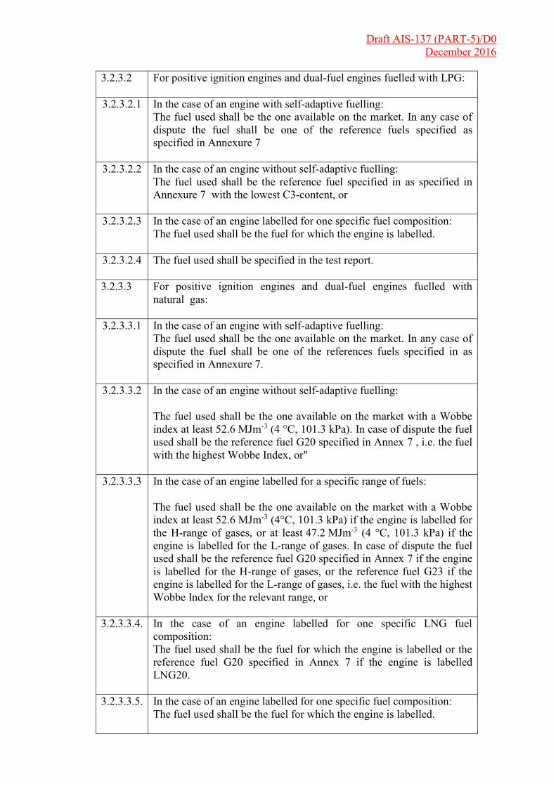
3.2.3.2 For positive ignition engines and dual-fuel engines fuelled with LPG:
3.2.3.2.1 In the case of an engine with self-adaptive fuelling: The fuel used shall be the one available on the market. In any case of dispute the fuel shall be one of the reference fuels specified as specified in Annexure 7
3.2.3.2.2 In the case of an engine without self-adaptive fuelling: The fuel used shall be the reference fuel specified in as specified in Annexure 7 with the lowest C3-content, or
3.2.3.2.3 In the case of an engine labelled for one specific fuel composition: The fuel used shall be the fuel for which the engine is labelled.
3.2.3.2.4 The fuel used shall be specified in the test report.
3.2.3.3 For positive ignition engines and dual-fuel engines fuelled with natural gas:
3.2.3.3.1 In the case of an engine with self-adaptive fuelling: The fuel used shall be the one available on the market. In any case of dispute the fuel shall be one of the references fuels specified in as specified in Annexure 7.
3.2.3.3.2 In the case of an engine without self-adaptive fuelling: The fuel used shall be the one available on the market with a Wobbe index at least 52.6 MJm-3 (4 °C, 101.3 kPa). In case of dispute the fuel used shall be the reference fuel G20 specified in Annex 7 , i.e. the fuel with the highest Wobbe Index, or"
3.2.3.3.3 In the case of an engine labelled for a specific range of fuels: The fuel used shall be the one available on the market with a Wobbe index at least 52.6 MJm-3 (4°C, 101.3 kPa) if the engine is labelled for the H-range of gases, or at least 47.2 MJm-3 (4 °C, 101.3 kPa) if the engine is labelled for the L-range of gases. In case of dispute the fuel used shall be the reference fuel G20 specified in Annex 7 if the engine is labelled for the H-range of gases, or the reference fuel G23 if the engine is labelled for the L-range of gases, i.e. the fuel with the highest Wobbe Index for the relevant range, or
3.2.3.3.4. In the case of an engine labelled for one specific LNG fuel composition: The fuel used shall be the fuel for which the engine is labelled or the reference fuel G20 specified in Annex 7 if the engine is labelled LNG20.
3.2.3.3.5. In the case of an engine labelled for one specific fuel composition: The fuel used shall be the fuel for which the engine is labelled.

Draft AIS-137 (PART-5)/D0 December 2016
3.2.3.3.6. The fuel used shall be specified in the test report.
3.2.3.4. For compression ignition engines and dual-fuel engines: The fuel used shall be the one available on the market. In any case of dispute, the fuel shall be the reference fuel as specified in Annexure 7 for compression ignition engines.
3.2.3.5. Positive ignition engines of vehicles that can run either on petrol or on a gaseous fuel, are to be tested with both fuels, in accordance with the provisions in paragraphs 3.2.3.1. to 3.2.3.3. The vehicles that can be fuelled with both petrol and a gaseous fuel, but where the petrol system is fitted for emergency purposes or starting only and of which the petrol tank cannot contain more than 15 liters of petrol will be regarded for the test as vehicles that can only run a gaseous fuel.
3.2.3.6. Dual-fuel engines or vehicles that have a diesel mode are to be tested with the fuels appropriate to each mode, in accordance with the provisions set in paragraphs 3.2.3.1 to 3.2.3.5.
3.2.4. Measurements shall be carried out according to the provisions of chapter 4 to this part.
3.2.5. The test report shall contain the results and all the calculations required to find the net power, as listed in the appendix to chapter 4 to this part. In order to draw up this document, the competent authority may use the report prepared by an approved or recognized laboratory pursuant to the provisions of this part.
3.3. Description of tests for measuring the net power and the
maximum 30 minutes power of electric drive trains
The electric drive train shall be equipped as specified in chapter 5 to this part. The electric drive train shall be supplied from a DC voltage source with a maximum voltage drop of 5 per cent depending on time and current (periods of less than 10 seconds excluded). The supply voltage of the test shall be given by the vehicle manufacturer. Note: If the battery limits the maximum 30 minutes power, the maximum 30 minutes power of an electric vehicle can be less than the maximum 30 minutes power of the drive train of the vehicle according to this test.
3.3.1. Determination of the net power
3.3.1.1. The motor and its entire equipment assembly must be conditioned at a temperature of 25 °C ± 5 °C for a minimum of two hours.
3.3.1.2. The net power test shall consist of a run at full setting of the power controller.

Draft AIS-137 (PART-5)/D0 December 2016
3.3.1.3. Just before beginning the test, the motor shall be run on the bench for three minutes delivering a power equal to 80 per cent of the maximum power at the speed recommended by the manufacturer.
3.3.1.4. Measurements shall be taken at a sufficient number of motor speeds to define correctly the power curve between zero and the highest motor speed recommended by the manufacturer. The whole test shall be completed within 5 minutes.
3.3.2. Determination of the maximum 30 minutes power
3.3.2.1. The motor and its entire equipment assembly must be conditioned at a temperature of 25 °C ± 5 °C for a minimum of four hours.
3.3.2.2. The electric drive train shall run at the bench at a power which is the best estimate of the manufacturer for the maximum 30 minutes power. The speed must be in a speed range, which the net power is greater than 90 per cent of the maximum power as measured in paragraph 3.3.1. This speed shall be recommended by the manufacturer.
3.3.2.3. Speed and power shall be recorded. The power must be in a range of ±5 per cent of the power value at the start of the test. The maximum 30 minutes power is the average of the power within the 30 minutes period.
3.4. Interpretation of results The net power and the maximum 30 minutes power for electric drive trains indicated by the manufacturer for the type of drive train shall be accepted if it does not differ by more than ±2 per cent for maximum power and more than ±4 per cent at the other measurement points on the curve with a tolerance of ±2 per cent for engine or motor speed, or within the engine or motor speed range (X1 min-1 + 2 per cent) to (X2 min-1 -2 per cent) (X1 < X2) from the values measured by the technical service on the drive train submitted for testing. In case of a dual-fuel engine, the net power indicated by the manufacturer shall be the one measured on the dual-fuel mode of that engine.

Draft AIS-137 (PART-5)/D0 December 2016
CHAPTER 2:
Technical Specification of engine.
(As per AIS: 007 Revision 5)

Draft AIS-137 (PART-5)/D0 December 2016
CHAPTER 3 :
Essential characteristics of the electric drive train and information concerning the conduct of tests:
(As per AIS: 007 Revision 5)
Draft AIS-137 (PART-5)/D0 December 2016
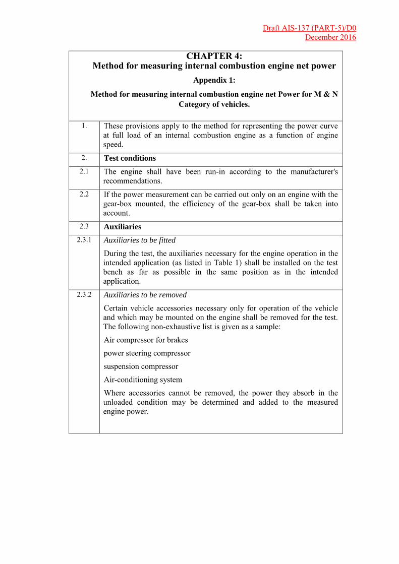
CHAPTER 4: Method for measuring internal combustion engine net power
Appendix 1:
Method for measuring internal combustion engine net Power for M & N
Category of vehicles.
1. These provisions apply to the method for representing the power curve at full load of an internal combustion engine as a function of engine speed.
2. Test conditions 2.1 The engine shall have been run-in according to the manufacturer's
recommendations. 2.2 If the power measurement can be carried out only on an engine with the
gear-box mounted, the efficiency of the gear-box shall be taken into account.
2.3 Auxiliaries
2.3.1 Auxiliaries to be fitted
During the test, the auxiliaries necessary for the engine operation in the intended application (as listed in Table 1) shall be installed on the test bench as far as possible in the same position as in the intended application.
2.3.2 Auxiliaries to be removed
Certain vehicle accessories necessary only for operation of the vehicle and which may be mounted on the engine shall be removed for the test. The following non-exhaustive list is given as a sample:
Air compressor for brakes power steering compressor
suspension compressor
Air-conditioning system
Where accessories cannot be removed, the power they absorb in the unloaded condition may be determined and added to the measured engine power.
Draft AIS-137 (PART-5)/D0 December 2016
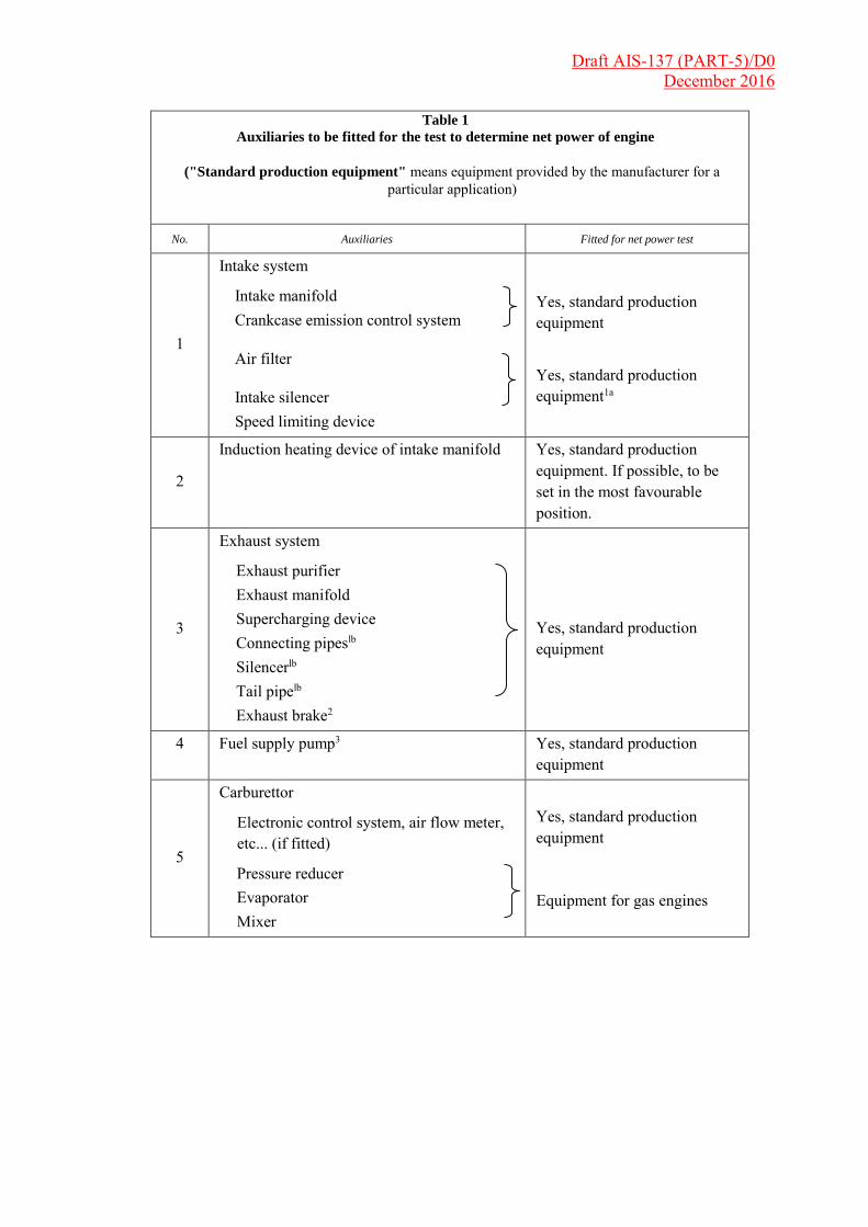
Table 1
Auxiliaries to be fitted for the test to determine net power of engine
("Standard production equipment" means equipment provided by the manufacturer for a particular application)
No. Auxiliaries Fitted for net power test
1
Intake system
Intake manifold Crankcase emission control system
Air filter
Intake silencer Speed limiting device
Yes, standard production equipment
Yes, standard production equipment1a
2
Induction heating device of intake manifold Yes, standard production equipment. If possible, to be set in the most favourable position.
3
Exhaust system
Exhaust purifier Exhaust manifold Supercharging device Connecting pipeslb Silencerlb Tail pipelb Exhaust brake2
Yes, standard production equipment
4 Fuel supply pump3 Yes, standard production equipment
5
Carburettor
Electronic control system, air flow meter, etc... (if fitted)
Pressure reducer Evaporator Mixer
Yes, standard production equipment
Equipment for gas engines
Draft AIS-137 (PART-5)/D0 December 2016
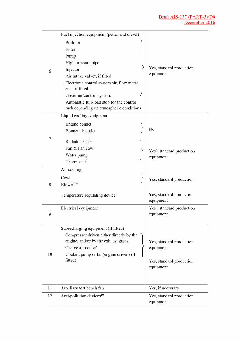
6
Fuel injection equipment (petrol and diesel)
Prefilter Filter Pump High pressure pipe Injector Air intake valve4, if fitted Electronic control system air, flow meter,
etc... if fitted Governor/control system.
Automatic full-load stop for the control rack depending on atmospheric conditions
Yes, standard production equipment
7
Liquid cooling equipment
Engine bonnet Bonnet air outlet
Radiator Fan5,6 Fan & Fan cowl Water pump Thermostat7
No
Yes5, standard production equipment
8
Air cooling
Cowl Blower5,6
Temperature regulating device
Yes, standard production
Yes, standard production equipment
9 Electrical equipment Yes8, standard production
equipment
10
Supercharging equipment (if fitted) Compressor driven either directly by the
engine, and/or by the exhaust gases Charge air cooler9 Coolant pump or fan(engine driven) (if
fitted)
Yes, standard production equipment
Yes, standard production equipment
11 Auxiliary test bench fan Yes, if necessary
12 Anti-pollution devices10 Yes, standard production equipment

Draft AIS-137 (PART-5)/D0 December 2016
Notes (1a) The complete intake system shall be fitted as provided for the intended application:
Where there is a risk of an appreciable effect on the engine power;
In the case of two-stroke and positive-ignition engines;
When the manufacturer requests that this should be done.
In other cases, an equivalent system may be used and a check should be made to ascertain that the intake pressure does not differ by more than 100 Pa from the limit specified by the manufacturer for a clean air filter.
(1b) The complete exhaust system shall be fitted as provided for the intended application:
Where there is a risk of an appreciable effect on the engine power;
In the case of two-stroke and positive-ignition engines;
When the manufacturer requests that this should be done.
In other cases, an equivalent system may be installed provided the pressure measured at the exit of the engine exhaust system does not differ by more than 1,000 Pa from that specified by the manufacturer.
The exit from the engine exhaust system is defined as a point 150 rom downstream from the termination of the part of the exhaust system mounted on the engine.
2. If an exhaust brake is incorporated in the engine, the throttle valve must be fixed in a fully open position.
3. The fuel feed pressure may be adjusted, if necessary, to reproduce the pressures existing in the particular
engine application (particularly when a "fuel return" system is used).
4. The air intake valve is the control valve for the pneumatic governor of the injection pump. The governor of the fuel injection equipment may contain other devices which may affect the amount of injected fuel
5. The radiator, the fan, the fan cowl, the water pump and the thermostat shall be located on the test bench in the same relative positions as on the vehicle. The cooling liquid circulation shall be operated by the engine water pump only.
Cooling of the liquid may be produced either by the engine radiator or by an externa circuit,provided that the pressure loss of this circuit and the pressure at the pump inlet remain substantially the same as those of the engine cooling system. The radiator shutter, if incorporated, shall be in the open position.
Where the fan, radiator and cowl system cannot conveniently be fitted to the engine, the power absorbed by the fan when separately mounted in its correct position in relation to the radiator and cowl (if used), must be determined at the speeds corresponding to the engine speeds used for measurement of the engine power either by calculation from standard characteristics or by practical tests. This power, corrected to the standard atmospheric conditions (293.2 K (20 °C) and 101.3 kPa), should be deducted from the corrected power.
6. Where a disconnectable or progressive fan or blower is incorporated, the test shal be made with the disconnectable fan (or blower) disconnected or with the progressive fanor blower running at maximum slip.
7. The thermostat may be fixed in the fully open position.
8. Minimum power of the generator: the power of the generator shall be limited to that necessary for the operation of accessories which are indispensable for the operation of the engine. If the connection of a battery is necessary, a fully charged battery in good order must be used.
9. Charge air cooled engines shall be tested with charge air cooling, whether liquid or air cooled, but if the engine manufacturer prefers, a test bench system may replace the air cooled cooler. In either case, the measurement of power at each speed shall be made with the same pressure drop and temperature drop of the engine air across the charge air cooler on the test bench system as those specified by the manufacturer for the system on the complete vehicle.
10. They may include, for example, EGR* system, catalytic convertor, thermal reactor, secondary air supply system and fuel evaporation protecting system.
*Exhaust gas recirculation.

Draft AIS-137 (PART-5)/D0 December 2016
2.3.3 Compression-ignition engine starting auxiliaries
For the auxiliaries used in starting compression-ignition engines, the two following cases shall be considered:
(a) Electric starting. A generator is fitted and supplies, where necessary, the auxiliaries essential for engine operation;
(b) Starting other than by electrical means. If there are any electrically operated accessories essential for engine operation for which a generator is fitted. Otherwise, it is removed.
In either case, the system for producing and storing the energy necessary for starting is fitted and operates in the unloaded condition.
2.4 Setting conditions
The setting conditions for the test to determine the net power are indicated in Table 2.
Table 2
Setting conditions
1. Setting of carburettor(s) In accordance with the manufacturer's production specifications and used without further alteration for the particular application
2. Setting of injection pump
delivery system
3. Ignition or injection
timing (timing curve)
4. Governor setting
5. Emission control devices
3. Data to be recorded
3.1. The net power test shall consist of a run at full throttle for positive-ignition engines and at fixed full load fuel-injection-pump setting for compression-ignition engines, the engine being equipped as specified in Table 1.
3.2 Data to be recorded are those indicated in paragraph 4. of the appendix to this annex. Performance data shall be obtained under stabilized operating conditions with an adequate fresh air supply to the engine. Combustion chambers may contain deposits, but in limited quantity. Test conditions, such as inlet air temperature, shall be selected as near to reference conditions (see para. 3.3. of this annex) as possible in order to minimize the magnitude of the correction factor.
3.3 The temperature of the inlet air to the engine (ambient air) shall be measured within 0.15 m upstream of the point of entry to the air cleaner, or, if no air cleaner is used, within 0.15 m of the air inlet horn. The thermometer or thermocouple shall be shielded from radiant heat and placed directly in the air stream. It shall also be shielded from fuel spray-back. A sufficient number of locations shall be used to give a representative average inlet temperature.
Draft AIS-137 (PART-5)/D0 December 2016
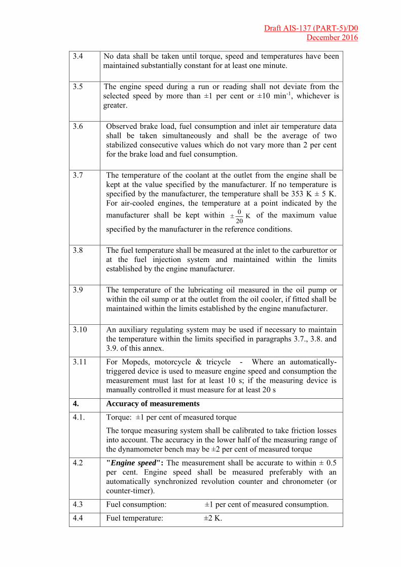
3.4 No data shall be taken until torque, speed and temperatures have been maintained substantially constant for at least one minute.
3.5 The engine speed during a run or reading shall not deviate from the selected speed by more than ±1 per cent or ±10 min-1, whichever is greater.
3.6 Observed brake load, fuel consumption and inlet air temperature data shall be taken simultaneously and shall be the average of two stabilized consecutive values which do not vary more than 2 per cent for the brake load and fuel consumption.
3.7 The temperature of the coolant at the outlet from the engine shall be kept at the value specified by the manufacturer. If no temperature is specified by the manufacturer, the temperature shall be 353 K ± 5 K. For air-cooled engines, the temperature at a point indicated by the manufacturer shall be kept within K
200
of the maximum value
specified by the manufacturer in the reference conditions.
3.8 The fuel temperature shall be measured at the inlet to the carburettor or at the fuel injection system and maintained within the limits established by the engine manufacturer.
3.9 The temperature of the lubricating oil measured in the oil pump or within the oil sump or at the outlet from the oil cooler, if fitted shall be maintained within the limits established by the engine manufacturer.
3.10 An auxiliary regulating system may be used if necessary to maintain the temperature within the limits specified in paragraphs 3.7., 3.8. and 3.9. of this annex.
3.11 For Mopeds, motorcycle & tricycle - Where an automatically-triggered device is used to measure engine speed and consumption the measurement must last for at least 10 s; if the measuring device is manually controlled it must measure for at least 20 s
4. Accuracy of measurements
4.1. Torque: ±1 per cent of measured torque
The torque measuring system shall be calibrated to take friction losses into account. The accuracy in the lower half of the measuring range of the dynamometer bench may be ±2 per cent of measured torque
4.2 "Engine speed": The measurement shall be accurate to within ± 0.5 per cent. Engine speed shall be measured preferably with an automatically synchronized revolution counter and chronometer (or counter-timer).
4.3 Fuel consumption: ±1 per cent of measured consumption.
4.4 Fuel temperature: ±2 K.

Draft AIS-137 (PART-5)/D0 December 2016
4.5 Engine inlet air temperature: ± 1 K.
4.6 Barometric pressure: ±100 Pa.
4.7 Pressure in intake-duct: ±50 Pa.
4.8 Pressure in exhaust duct: ±200 Pa.
5. Power correction factors
5.1 Definition
The power correction factor is the coefficient to determine the engine power under the reference atmospheric conditions specified in paragraph 5.2. below.
Where
Po = αP
Po is the corrected power (i.e. power under reference atmospheric conditions)
α is the correction factor (αa or αd)
P is the measured power (test power)
5.2 Reference atmospheric conditions
5.2.1 Temperature (To): 298 K (25 °C)
5.2.2. Dry pressure (Pso ): 99 kPa
Note: The dry pressure is based on a total pressure of 100 kPa and a water vapour pressure of 1 kPa.
5.3 Test atmospheric conditions
The atmospheric conditions during the test shall be the following:
5.3.1 Temperature (T)
For positive-ignition engines 288 K ≤ T ≤ 308 K
For compression-ignition engines 283 K ≤ T ≤ 313 K
5.3.2 Pressure (Ps)
80 kPa ≤ Ps ≤ 110 kPa
5.4 Determination of correction factor αa and αd1
5.4.1 Naturally aspirated or pressure-charged positive-ignition engine factor αa
The correction factor αa is obtained by applying the formula:
αa = 6.02.1
29899
T
Ps
(2)
1 The test may be carried out in air-conditioned test room whwre the atmospheric conditions may be controlled 2 In the case of engines fitted with automatic air temperature control, if the device is such that at full load at 25 °C no
heated air is added, the test shall be carried out with the device fully closed. If the device is still operating at 25 °C then the test is made with the device operating normally and the exponent of the temperature term in the correction factor shall be taken as zero (no temperature correction).
Draft AIS-137 (PART-5)/D0 December 2016
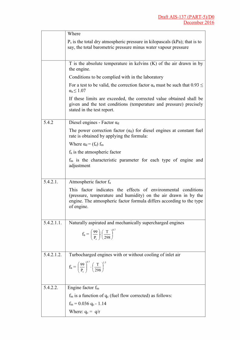
Where
Ps is the total dry atmospheric pressure in kilopascals (kPa); that is to say, the total barometric pressure minus water vapour pressure
T is the absolute temperature in kelvins (K) of the air drawn in by the engine.
Conditions to be complied with in the laboratory
For a test to be valid, the correction factor αa must be such that 0.93 ≤ αa ≤ 1.07
If these limits are exceeded, the corrected value obtained shall be given and the test conditions (temperature and pressure) precisely stated in the test report.
5.4.2 Diesel engines - Factor αd
The power correction factor (αd) for diesel engines at constant fuel rate is obtained by applying the formula:
Where αd = (fa) fm
fa is the atmospheric factor
fm is the characteristic parameter for each type of engine and adjustment
5.4.2.1. Atmospheric factor fa
This factor indicates the effects of environmental conditions (pressure, temperature and humidity) on the air drawn in by the engine. The atmospheric factor formula differs according to the type of engine.
5.4.2.1.1. Naturally aspirated and mechanically supercharged engines
fa = 7.0
s 298T
P99
5.4.2.1.2. Turbocharged engines with or without cooling of inlet air
fa = 5.17.0
s 298T
P99
5.4.2.2. Engine factor fm
fm is a function of qc (fuel flow corrected) as follows:
fm = 0.036 qc - 1.14
Where: qc = q/r
Draft AIS-137 (PART-5)/D0 December 2016
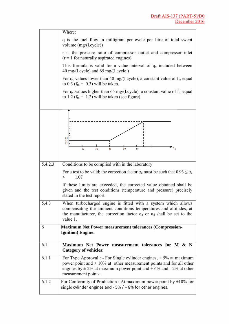
Where:
q is the fuel flow in milligram per cycle per litre of total swept volume (mg/(l.cycle))
r is the pressure ratio of compressor outlet and compressor inlet (r = 1 for naturally aspirated engines)
This formula is valid for a value interval of qc included between 40 mg/(l.cycle) and 65 mg/(l.cycle.)
For qc values lower than 40 mg/(l.cycle), a constant value of fm equal to 0.3 (fm = 0.3) will be taken.
For qc values higher than 65 mg/(l.cycle), a constant value of fm equal to 1.2 (fm = 1.2) will be taken (see figure):
5.4.2.3 Conditions to be complied with in the laboratory
For a test to be valid; the correction factor αd must be such that 0.93 ≤ αd ≤ 1.07
If these limits are exceeded, the corrected value obtained shall be given and the test conditions (temperature and pressure) precisely stated in the test report.
5.4.3 When turbocharged engine is fitted with a system which allows compensating the ambient conditions temperatures and altitudes, at the manufacturer, the correction factor αa or αd shall be set to the value 1.
6 Maximum Net Power measurement tolerances (Compression-
Ignition) Engine:
6.1 Maximum Net Power measurement tolerances for M & N
Category of vehicles:
6.1.1 For Type Approval : - For Single cylinder engines, ± 5% at maximum power point and ± 10% at other measurement points and for all other engines by ± 2% at maximum power point and + 6% and - 2% at other measurement points.
6.1.2 For Conformity of Production : At maximum power point by ±10% for single cylinder engines and - 5% / + 8% for other engines.

Draft AIS-137 (PART-5)/D0 December 2016
Results of tests for measuring net engine power
This form shall be completed by the laboratory performing the test.
1. Test conditions
1.1. Pressures measured at maximum power
1.1.1. Total barometric pressure: Pa
1.1.2. Water vapour pressure: Pa
1.1.3. Exhaust pressure Pa
1.2. Temperatures measured at maximum power
1.2.1. Of the intake air: K
1.2.2. At the outlet of the engine intercooler: K
1.2.3. Of the cooling fluid
1.2.3.1. At the engine cooling fluid outlet: K3
1.2.3.2. At the reference point in the case of air cooling: K1
1.2.4. Of the lubricating oil: (indicate point of measurement) K
1.2.5. Of the fuel
1.2.6. Of the exhaust measured at the point adjacent to the outlet flange(s) of the exhaust manifold(s):
°C
1.2.5.1. At the fuel pump inlet: K
1.2.5.2. In the fuel consumption measuring device: K
1.3. Engine speed when idling: min-1
1.4. Characteristics of the dynamometer
1.4.1. Make:……………………………. Model:………………..
1.4.2. Type:
1.5. Characteristics of the opacimeter
1.5.1. Make:
1.5.2. Type:
2. Fuel
2.1. For positive-ignition engines operating on liquid fuel
2.1.1. Make:
2.1.2. Specification:
2.1.3. Anti-knock additive (lead, etc.):
2.1.3.1. Type:
2.1.3.2. Content: mg/1
2.1.4. Octane number RON: (ASTM D 26 99-70)
2.1.4.1. MON No:
2.1.4.2. Specific density: g/cm3 at 288 K
2.1.4.3. Lower calorific value: kJ/kg
1 Delete as appropriate.
Draft AIS-137 (PART-5)/D0 December 2016
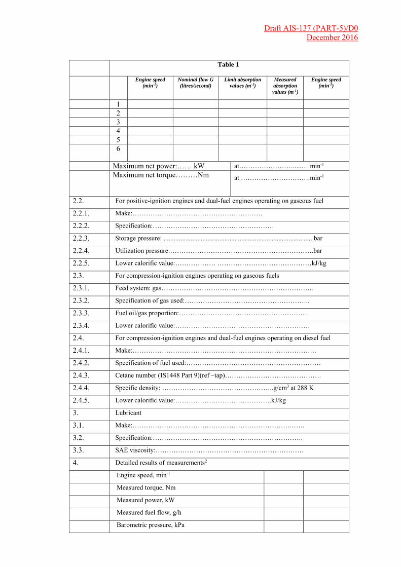
Table 1
Engine speed
(min-1)
Nominal flow G
(litres/second)
Limit absorption
values (m-1)
Measured
absorption
values (m-1)
Engine speed
(min-1)
1 2 3 4 5
6
Maximum net power:…… kW at…………………….....… min-1
Maximum net torque………Nm
at ………………………….min-1
2.2. For positive-ignition engines and dual-fuel engines operating on gaseous fuel
2.2.1. Make:………………………………………………….
2.2.2. Specification:………………………………………………
2.2.3. Storage pressure: .........................................................................................bar
2.2.4. Utilization pressure:……………………………………………………….bar
2.2.5. Lower calorific value:……………… ……………………………………kJ/kg
2.3. For compression-ignition engines operating on gaseous fuels
2.3.1. Feed system: gas …………………………………………………………..
2.3.2. Specification of gas used:………………………………………………..
2.3.3. Fuel oil/gas proportion:………………………………………………….
2.3.4. Lower calorific value:……………………………………………………
2.4. For compression-ignition engines and dual-fuel engines operating on diesel fuel
2.4.1. Make:……………………………………………………………………….
2.4.2. Specification of fuel used:……………………………………………………
2.4.3. Cetane number (IS1448 Part 9)(ref –tap)…………………………………….
2.4.4. Specific density: …………………………………………..g/cm3 at 288 K
2.4.5. Lower calorific value:…………………………………….kJ/kg
3. Lubricant
3.1. Make:…………………………………………………………….…….
3.2. Specification:………………………………………………………….
3.3. SAE viscosity:…………………………………………………………
4. Detailed results of measurements2
Engine speed, min-1
Measured torque, Nm
Measured power, kW
Measured fuel flow, g/h
Barometric pressure, kPa

Draft AIS-137 (PART-5)/D0 December 2016
Water vapour pressure, kPa
Inlet air temperature, K
Power to be added for No. 1 auxiliaries in excess No. 2 of Table 1, kW No. 3
Power correction factor
Corrected brake power, kW (with/without1 fan)
Power of fan, kW (to be subtracted if fan not fitted)
Net torque, kW
Net torque, Nm
Corrected specific fuel consumption g/(kWh)2
Cooling liquid temperature at outlet, K
Lubricating oil temperature t measuring point, K
Air temperature after pressure-charger, K3
Fuel temperature at injection pump inlet, K
Air temperature after charge air cooler, K3
Pressure after pressure-charger, kPa3
Pressure after charge air cooler, kPa
Notes:
l Delete as appropriate.
2 Calculated with the net power for compression-ignition and positive-ignition engines, in the latter case multiplied by the power correction factor.
____________ 2 The characteristic curves of the net power and the net torque shall be drawn as a function of the engine
speed.
Draft AIS-137 (PART-5)/D0 December 2016
Appendix 2:
Test at steady speeds over the full-load curve
1 Scope :
This Chapter describes the method of determining emissions of visible pollutants at different steady speeds over the full load curve to be carried out either on an engine or on a vehicle.
The emission of visible exhaust pollution from C.I. engines which are intended for fitting to vehicles of categories L, M & N
2. Measurement Principle :
2.1 The opacity of the exhaust gases produced by the engine shall be measured with the engine running under full-load and at steady speed.
2.2 A sufficient number of measurements will be carried out ranging between the maximum rated speed and the minimum rated speed. The extreme points of measurement shall be situated at the limits of interval defined above and one point of measurement will coincide with the speed at which the engine develops its maximum power and the speed at which it develops maximum torque.
3. Test Conditions :
3.1 Vehicle or engine :
3.1.1 The engine or the vehicle shall be submitted in good mechanical condition. The engine/vehicle shall have been run in as recommended by the manufacturer.
3.1.2 The engine shall be tested with the equipment prescribed in Chapter 4 of this Part.
3.1.3 The settings of the engine shall be those prescribed by the manufacturer and shown in Chapter 4 of this Part.
3.1.4 In the case of a test on an engine the power of the engine shall be measured in accordance with Appendix 1 of this Part and it should meet the requirements of power tolerance given in Appendix 1, 2 & 3. In the case of a test on a vehicle, it should be established that the fuel flow is not less than that declared by the manufacturer.
3.1.5 The exhaust device shall not have any orifice through which the gases emitted by the engine might be diluted. In cases where an engine has several exhaust outlets, these shall be connected to a single outlet in which the opacity measurement shall be made.
3.1.6 The engine shall be in the normal working condition prescribed by the manufacturer. In particular, the cooling water and the oil shall each be at the normal temperature prescribed by the manufacturer.
Draft AIS-137 (PART-5)/D0 December 2016
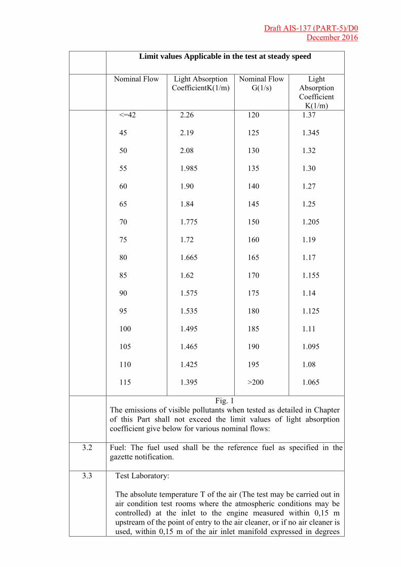
Limit values Applicable in the test at steady speed
Nominal Flow Light Absorption CoefficientK(1/m)
Nominal Flow G(1/s)
Light Absorption Coefficient
K(1/m) <=42
45 50 55 60 65 70 75 80 85 90 95 100 105 110 115
2.26 2.19 2.08 1.985 1.90 1.84 1.775 1.72 1.665 1.62 1.575 1.535 1.495 1.465 1.425 1.395
120 125 130 135 140 145 150 160 165 170 175 180 185 190 195 >200
1.37 1.345 1.32 1.30 1.27 1.25 1.205 1.19 1.17 1.155 1.14 1.125 1.11 1.095 1.08 1.065
Fig. 1 The emissions of visible pollutants when tested as detailed in Chapter of this Part shall not exceed the limit values of light absorption coefficient give below for various nominal flows:
3.2 Fuel: The fuel used shall be the reference fuel as specified in the gazette notification.
3.3 Test Laboratory: The absolute temperature T of the air (The test may be carried out in air condition test rooms where the atmospheric conditions may be controlled) at the inlet to the engine measured within 0,15 m upstream of the point of entry to the air cleaner, or if no air cleaner is used, within 0,15 m of the air inlet manifold expressed in degrees

Draft AIS-137 (PART-5)/D0 December 2016
Kelvin, and the atmospheric pressure Ps, expressed in Kilopascals, shall be measured, and the atmospheric factor F shall be determined as give below :Naturally aspirated and mechanically super charged engines:- F = (99/Ps) * (T/298)0.7 Turbo super charge engines with or without cooling of inlet air F = (99/Ps) 0.7 * (T/298) 1.5
3.3.1 For a the to be recognised as valid, the parameter fa shall be such that 0.98 ≤ fa ≤ 1.02.
3.4 Sampling and measuring apparatus: The light-absorption coefficient of the exhaust gases shall be measured with an opacimeter satisfying the conditions of characteristics of opacimeter & installation and use of opacimeter.
4 Evaluation of the Absorption Coefficient:
4.1 For each of the six engine speeds at which the absorption coefficient is measured pursuant to Paragraph 2.2 above, the nominal gas flow shall be calculated by mean of the following formulae: for two-stroke engines G = V * n/60 four-stroke engines G = V * n/120 where – G - nominal gas flow, in liters per second, (l/s) V - cylinder capacity of the engine, in liters, (l) n - engine speed, in revolutions per minute (rpm ),
4.2 Correction of Exhaust gas opacity: For the correction factor description please refer paras 4.2.1 to 4.2.5. This is not applicable since 01.04.96.
4.2.1 The smoke density should be corrected to reference atmospheric conditions of 100 kpa and 298K.
4.2.2 Correction data exist only for certain proprietary instruments. The light obscuration smokemeter for which correction data is given in Fig.2, is the Hartridge opacimeter with an effective exhaust gas column length of approximately 0.43 m and applicable for Four stroke naturally aspirated engines only. The correction shall be applied as follows : Corrected exhaust gas opacity = observed exhaust gas opacity ± Opacity Correction.
4.2.3 For test atmospheric conditions outside the limits covered by the nomogram given in Fig.2, the maximum possible correction factor from the nomogram will be applied.

Draft AIS-137 (PART-5)/D0 December 2016
4.2.4 For engines other than Four-stroke naturally aspirated engines, no correction shall be applied, but if the inlet air density (ignoring humidity) is more than 5 % different from that given by the standard conditions, mention shall be made of it but no values are specified at present as there is insufficient data for such engines. This will be supplemented at a later stage.
4.2.5 When the exhaust gas opacity is less than 20 or greater than 80 Hartridge smoke units, no correction shall be applied, and the observed readings shall be stated. If the corrected exhaust gas opacity shall be stated ‘as less than 20’ or ‘greater than 80’ Hartridge smoke units, as appropriate.
4.3 Where the value of the nominal flow is not one of those given in the table above. the limit value applicable shall be obtained by interpolation on the principle of proportional parts.
4.4 Fig.1of above shows the correlation between light absorption coefficient expressed in m , % opacity, Hartridge Smoke Units (HSU) and Bosch Smoke Units (BSU).

Draft AIS-137 (PART-5)/D0 December 2016
Appendix 3:
Test under free acceleration
1. Scope:
This Chapter describes the method of determining the emissions of visible pollutants during the free acceleration test The test shall be carried out on an engine installed on a test bench or on a vehicle. If the engine test is a bench test, it shall be carried out as soon as possible after the test for measurement of opacity under full load at steady speed. In particular the cooling water and the oil shall be at the normal temperature stated by the manufacturer. If the test is carried out on a stationary vehicle, the engine shall first be brought to normal operating conditions during a road run or on a dynamic test. The test shall be carried out as soon as possible after completion of this warming up period.. This is applicable for naturally aspirated and supercharged (turbocharged) engine/vehicles.
1.1 The emissions of visible pollutants under free acceleration, when tested according to the procedure detailed in paragraph 3 below shall not exceed 2.45/m when expressed as light absorption coefficient.
1.2 At the request of the manufacturer additional tests described in paragraph 3 below of this Part shall be performed to obtain free acceleration values for derivatives of the approved engine permitted by para. 5.0 below.
1.3 If the engine manufacturer desires to have the visible pollutants measured over a smaller range of torque and/or speed than is allowed by Para 5.0 below, then the approval of the engine type will be for the limited range of torque and speed.
1.4 If at a later stage it is desired to extend the approval of the engine to cover the whole of the torque/speed range allowed by Para 5.0 below then a further engine would have to be submitted for test so that the visible pollutants can be established for that part of the load/speed range which has previously been omitted.
1.5 If in order to meet some parts of the torque and speed ranges it is necessary to have additional specifications then these shall be declared in the format of essential characteristics of the engine.
1.6 The value of the free acceleration absorption coefficient for the engine will be appropriately chosen in accordance with iterated speed and torque from the matrix of values established by the method in para. 3 of this appendix.
2 Test Conditions:
2.1 The test shall be carried out on an engine installed on a test bench or on vehicle.
2.1.1 If the engine test is a bench test it shall be carried out as soon as possible after the test for measurement of opacity under full load at steady speed. In particular, the cooling water and the oil shall be at the normal temperatures stated by the manufacturer.
Draft AIS-137 (PART-5)/D0 December 2016
2.1.2 If the test is carried out on a stationary vehicle the engine shall first be
brought to normal operating conditions during a road run or on a dynamic test. The test shall be carried out as soon as possible after completion of this warming up period.
2.2 The combustion chamber shall not have been cooled or fouled by a prolonged period of idling preceding the test.
2.3 The test conditions prescribed in Appendix 2 if para 3.1, 3.2 and 3.3 of Chapter 4 of this Part shall apply.
2.4 The conditions prescribed with regard to the sampling and measuring apparatus shall apply.
3 Test Methods :
3.1 The visible pollutants during free acceleration shall be measured with the
engine in the maximum rated speed and maximum power condition.
3.2 At the request of the manufacturer, measurements shall also be made over a matrix of up to five other power/speed combinations for the engines de-rated for speed/power to cover the range of speed and power allowed for in Para 3.2.1 of Chapter 1 of this Part covering the modification of an engine type. In this case the steady state visible pollutants will also be measured with the engine rated at these other points, by the method described in Chapter 3 of this Part, to enable the free acceleration absorption coefficient to be corrected in accordance with Paragraph 4 below. These values shall be recorded in the approval certificate.
3.2.1 At the request of the manufacturer additional tests described in appendix 2 & 3 shall be performed to obtain free acceleration values for derivatives of the approved engine permitted by paragraphs 3.2.2 & 3.3.3
3.2.2 For the purposes of this Chapter with regard to the emission of visible pollutants the modifications may be classified as follows: (1) Modifications which require a new approval with tests. (2) Modifications which require a new approval without tests. (3) Modifications which may require new tests however without new approval. (4) Modifications which do not require complementary tests or new approvals. The above classifications (1), (2), (3) and (4) are marked on each line of the corresponding characteristics of the vehicle and C.I. Engine and.
3.2.3 Irrespective of these classifications in paragraph 3.2.2 a new approval, with tests, i.e. Classification (1), will automatically be required unless the engine also respects the following conditions: Maximum rated speed not greater than 100 per cent nor less than 75 per cent of that of the engine in the approval test, Minimum rated speed not less than that of the engine in the approval test, Torque rating not greater than 100 per cent, nor less than 70 per cent of that of the engine at that speed in the approval test, Steady state absorption values are not greater than 1.1 times the values
Draft AIS-137 (PART-5)/D0 December 2016
obtained in the approval test and do not exceed the prescribed limits in figure 1 of appendix 2, Exhaust back pressure not greater than that of the engine in the type approval test,
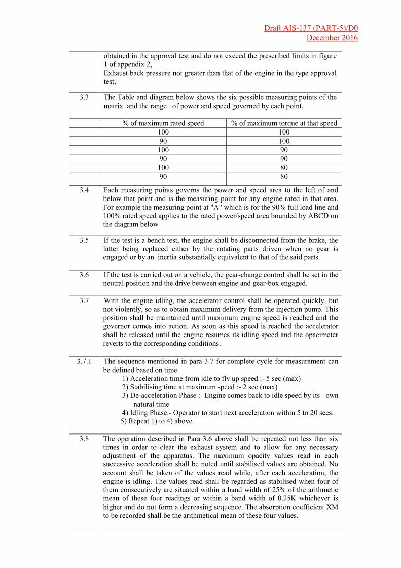
3.3 The Table and diagram below shows the six possible measuring points of the matrix and the range of power and speed governed by each point.
% of maximum rated speed % of maximum torque at that speed 100 100 90 100 100 90 90 90 100 80 90
80
3.4 Each measuring points governs the power and speed area to the left of and below that point and is the measuring point for any engine rated in that area. For example the measuring point at "A" which is for the 90% full load line and 100% rated speed applies to the rated power/speed area bounded by ABCD on the diagram below
3.5 If the test is a bench test, the engine shall be disconnected from the brake, the latter being replaced either by the rotating parts driven when no gear is engaged or by an inertia substantially equivalent to that of the said parts.
3.6 If the test is carried out on a vehicle, the gear-change control shall be set in the neutral position and the drive between engine and gear-box engaged.
3.7 With the engine idling, the accelerator control shall be operated quickly, but not violently, so as to obtain maximum delivery from the injection pump. This position shall be maintained until maximum engine speed is reached and the governor comes into action. As soon as this speed is reached the accelerator shall be released until the engine resumes its idling speed and the opacimeter reverts to the corresponding conditions.
3.7.1 The sequence mentioned in para 3.7 for complete cycle for measurement can be defined based on time.
1) Acceleration time from idle to fly up speed :- 5 sec (max) 2) Stabilising time at maximum speed :- 2 sec (max) 3) De-acceleration Phase :- Engine comes back to idle speed by its own
natural time 4) Idling Phase:- Operator to start next acceleration within 5 to 20 secs.
5) Repeat 1) to 4) above.
3.8 The operation described in Para 3.6 above shall be repeated not less than six times in order to clear the exhaust system and to allow for any necessary adjustment of the apparatus. The maximum opacity values read in each successive acceleration shall be noted until stabilised values are obtained. No account shall be taken of the values read while, after each acceleration, the engine is idling. The values read shall be regarded as stabilised when four of them consecutively are situated within a band width of 25% of the arithmetic mean of these four readings or within a band width of 0.25K whichever is higher and do not form a decreasing sequence. The absorption coefficient XM to be recorded shall be the arithmetical mean of these four values.

Draft AIS-137 (PART-5)/D0 December 2016
3.9 In cases where the engine has several exhaust outlets. the tests shall be carried
out with all the outlets joined in an adequate device ensuring mixture of the gases and ending in a single orifice. Free acceleration tests, however, may be carried out on each outlet. In this case the value to be used for calculating the correction to the absorption coefficient shall be the arithmetical mean of the values recorded at each outlet, and the test shall be regarded as valid only if the extreme values measured do not differ by more than 0.15 m -1 .
4 Determination of the Corrected Value of the Absorption Coefficient: Applicable where steady speed absorption coefficient has been effectively established on the same engine derivative.
4.1 Notation: XM - value of the absorption coefficient under free acceleration measured as prescribed in Paragraph 3.8 above; XL - corrected value of the absorption coefficient under free acceleration; SM - value of the absorption coeff. measured at steady speed as prescribed in Para 2.2 of Chapter 3 of this Part which is closest to the prescribed limit value corresponding to the same nominal flow;
SL - value of the absorption coefficient as prescribed in Paragraph 4.1 of Chapter 3 of this Part, for the nominal flow corresp. to the point of measurement which gave the value SM;
4.2 The absorption coefficients being expressed in m-1.The corrected value X is given by the smaller of the following two expressions :
XL = SL * XM / SM or XL = XM + 0.5
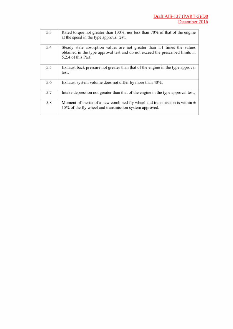
5. Extension Criteria: The approval may be extended without carrying out any type test for the following conditions ;
5.1 Maximum rated speed not greater than 100% nor less than 75% of that of the engine in the type approval test;
5.2 Minimum rated speed not less than that of the engine in the type approval test;
Draft AIS-137 (PART-5)/D0 December 2016
5.3 Rated torque not greater than 100%, nor less than 70% of that of the engine
at the speed in the type approval test;
5.4 Steady state absorption values are not greater than 1.1 times the values obtained in the type approval test and do not exceed the prescribed limits in 5.2.4 of this Part.
5.5 Exhaust back pressure not greater than that of the engine in the type approval test;
5.6 Exhaust system volume does not differ by more than 40%;
5.7 Intake depression not greater than that of the engine in the type approval test;
5.8 Moment of inertia of a new combined fly wheel and transmission is within ± 15% of the fly wheel and transmission system approved.
Draft AIS-137 (PART-5)/D0 December 2016
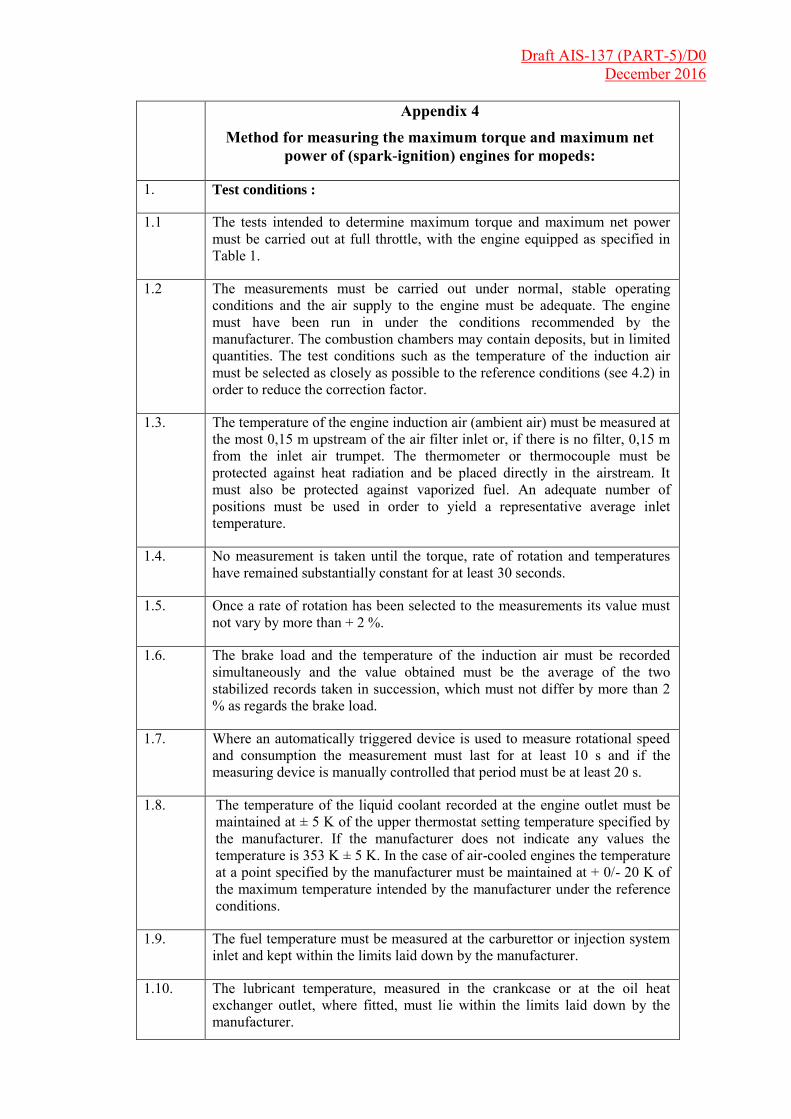
Appendix 4
Method for measuring the maximum torque and maximum net
power of (spark-ignition) engines for mopeds:
1. Test conditions :
1.1 The tests intended to determine maximum torque and maximum net power must be carried out at full throttle, with the engine equipped as specified in Table 1.
1.2 The measurements must be carried out under normal, stable operating conditions and the air supply to the engine must be adequate. The engine must have been run in under the conditions recommended by the manufacturer. The combustion chambers may contain deposits, but in limited quantities. The test conditions such as the temperature of the induction air must be selected as closely as possible to the reference conditions (see 4.2) in order to reduce the correction factor.
1.3. The temperature of the engine induction air (ambient air) must be measured at the most 0,15 m upstream of the air filter inlet or, if there is no filter, 0,15 m from the inlet air trumpet. The thermometer or thermocouple must be protected against heat radiation and be placed directly in the airstream. It must also be protected against vaporized fuel. An adequate number of positions must be used in order to yield a representative average inlet temperature.
1.4. No measurement is taken until the torque, rate of rotation and temperatures have remained substantially constant for at least 30 seconds.
1.5. Once a rate of rotation has been selected to the measurements its value must not vary by more than + 2 %.
1.6. The brake load and the temperature of the induction air must be recorded simultaneously and the value obtained must be the average of the two stabilized records taken in succession, which must not differ by more than 2 % as regards the brake load.
1.7. Where an automatically triggered device is used to measure rotational speed and consumption the measurement must last for at least 10 s and if the measuring device is manually controlled that period must be at least 20 s.
1.8. The temperature of the liquid coolant recorded at the engine outlet must be maintained at ± 5 K of the upper thermostat setting temperature specified by the manufacturer. If the manufacturer does not indicate any values the temperature is 353 K ± 5 K. In the case of air-cooled engines the temperature at a point specified by the manufacturer must be maintained at + 0/- 20 K of the maximum temperature intended by the manufacturer under the reference conditions.
1.9. The fuel temperature must be measured at the carburettor or injection system inlet and kept within the limits laid down by the manufacturer.
1.10. The lubricant temperature, measured in the crankcase or at the oil heat exchanger outlet, where fitted, must lie within the limits laid down by the manufacturer.
Draft AIS-137 (PART-5)/D0 December 2016
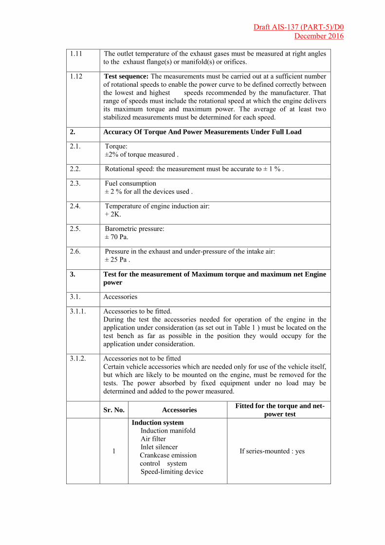
1.11 The outlet temperature of the exhaust gases must be measured at right angles
to the exhaust flange(s) or manifold(s) or orifices.
1.12 Test sequence: The measurements must be carried out at a sufficient number of rotational speeds to enable the power curve to be defined correctly between the lowest and highest speeds recommended by the manufacturer. That range of speeds must include the rotational speed at which the engine delivers its maximum torque and maximum power. The average of at least two stabilized measurements must be determined for each speed.
2. Accuracy Of Torque And Power Measurements Under Full Load
2.1. Torque: ±2% of torque measured .
2.2. Rotational speed: the measurement must be accurate to ± 1 % .
2.3. Fuel consumption ± 2 % for all the devices used .
2.4. Temperature of engine induction air: + 2K.
2.5. Barometric pressure: ± 70 Pa.
2.6. Pressure in the exhaust and under-pressure of the intake air: ± 25 Pa .
3. Test for the measurement of Maximum torque and maximum net Engine
power
3.1. Accessories
3.1.1. Accessories to be fitted. During the test the accessories needed for operation of the engine in the application under consideration (as set out in Table 1 ) must be located on the test bench as far as possible in the position they would occupy for the application under consideration.
3.1.2. Accessories not to be fitted Certain vehicle accessories which are needed only for use of the vehicle itself, but which are likely to be mounted on the engine, must be removed for the tests. The power absorbed by fixed equipment under no load may be determined and added to the power measured.
Sr. No. Accessories
Fitted for the torque and net-
power test
1
Induction system
Induction manifold Air filter Inlet silencer
Crankcase emission control system
Speed-limiting device
If series-mounted : yes

Draft AIS-137 (PART-5)/D0 December 2016
2
Exhaust system
Exhaust clean-up system Manifold Pipework (1) Silencer (1) Exhaust pipe (1)
If series-mounted: yes
3 Carburettor If series-mounted: yes
4
Fuel injection system Upstream filter Filter Pump Pipework Injector Where fitted, air inlet flap (2) Regulator (if fitted)
If series-mounted: yes
5
Liquid-cooling equipment Radiator Fan (4) (5) Water Pump Thermostat (6)
If series-mounted: yes))(3)
6
Air cooling Cowling Blower (4) (5) Temperature regulator Auxiliary bench blower
If series-mounted: yes, if necessary
7
Electrical equipment
If series-mounted: yes (7)
8
Anti-pollution devices
If series-mounted: yes
9
Lubrication system Oil feeder
If series-mounted: yes
(1) If it is difficult to use the standard exhaust system an exhaust system causing an equivalent pressure drop may be fitted for the test with the agreement of the manufacturer. In .the test laboratory when the engine is in operation the exhaust gas extraction system must not cause in the extraction flue at the point where it is connected to the vehicle's exhaust system a pressure differing from atmospheric pressure by ±740 Pa (7,40 mbar), unless, before the test, the manufacturer accepts a higher back pressure.
(2) The air inlet flap must be that which controls the pneumatic inject pump regulator.
(3) The radiator, fan, fan nozzle, water pump and thermostat must, on the test bench, occupy the same position relative to each other as if they were on the vehicle. The liquid coolant must be circulated solely by the water pump for the engine. The coolant may be cooled either by the engine radiator or by an outside circuit, provided that the pressure drops within that circuit remain substantially the same as thosein the engine cooling system. Where fitted the engine blind must be open.
(4) Where a fan or blower may be disengaged the net engine power must first of all be stated with the fan (or blower) disengaged, followed by the net engine power with the fan (or blower) engaged.
(5) Where a fixed electrically or mechanically-operated fan cannot be fitted on the test bench the power absorbed by that fan must be determined at the same rotational speeds as those used when the engine power is measured. That power is deducted from the corrected power in order to obtain the net power,
(6) The thermostat may be locked in the fully-open position. (7) Minimum generator output: the generator supplies the current that is strictly needed to supply the
accessories that are essential to the operation of the engine. The battery must not receive any charge during the test.
Draft AIS-137 (PART-5)/D0 December 2016
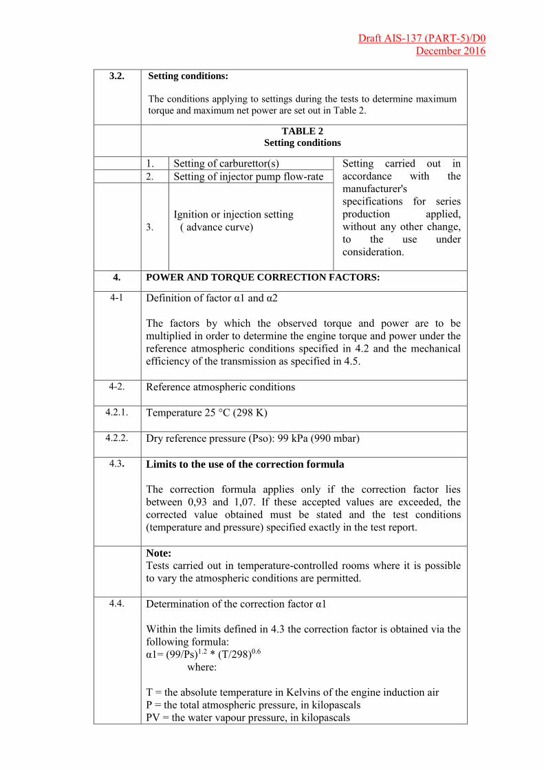
3.2. Setting conditions:
The conditions applying to settings during the tests to determine maximum torque and maximum net power are set out in Table 2.
TABLE 2
Setting conditions
1. Setting of carburettor(s) Setting carried out in accordance with the manufacturer's specifications for series production applied, without any other change, to the use under consideration.
2. Setting of injector pump flow-rate
3. Ignition or injection setting
( advance curve)
4. POWER AND TORQUE CORRECTION FACTORS:
4-1 Definition of factor α1 and α2 The factors by which the observed torque and power are to be multiplied in order to determine the engine torque and power under the reference atmospheric conditions specified in 4.2 and the mechanical efficiency of the transmission as specified in 4.5.
4-2. Reference atmospheric conditions
4.2.1. Temperature 25 °C (298 K)
4.2.2. Dry reference pressure (Pso): 99 kPa (990 mbar)
4.3. Limits to the use of the correction formula
The correction formula applies only if the correction factor lies between 0,93 and 1,07. If these accepted values are exceeded, the corrected value obtained must be stated and the test conditions (temperature and pressure) specified exactly in the test report.
Note:
Tests carried out in temperature-controlled rooms where it is possible to vary the atmospheric conditions are permitted.
4.4. Determination of the correction factor α1 Within the limits defined in 4.3 the correction factor is obtained via the following formula: α1= (99/Ps)1.2 * (T/298)0.6 where: T = the absolute temperature in Kelvins of the engine induction air P = the total atmospheric pressure, in kilopascals PV = the water vapour pressure, in kilopascals

Draft AIS-137 (PART-5)/D0 December 2016
PS = P - PV This formula applies to the torque and power read-off at the brake without taking account of the mechanical efficiency of the engine.
4.5 Determination of the correction factor for mechanical efficiency of the transmission α2 Determination of the factor α2 — where the measuring point is the crankshaft output side this factor must be 1 , — where the measuring point is not the output side of the crankshaft this factor is calculated via the formula: α2 1/nt where nt is the efficiency of the transmission located between the crankshaft and measuring point. This transmission efficiency nt is determined via the product (multiplication) of efficiency nj of each of the components of the transmission : nt = n1 x n2 ……. nj Efficiency nj of each of the components of the transmission is shown in the following table :
Type Efficiency
Gear wheel
Spur gear 0,98 Helical gear 0,97 Bevel gear 0,96
Chain Roller 0,95 Silent 0,98
Belt Cogged 0,95 Vee 0,94
Hydraulic coupling or convector
Hydraulic coupling (1) 0,92 Hydraulic convertor (1)
0,92
(1) If not locked up.
5. Maximum Torque And Maximum Net Power Measurement Tolerances
5.1. The maximum torque and the maximum net power of the engine as
determined by the technical service may differ by ± 10% of the value specified by the manufacturer if the power measured is ≤1 kW and ± 5% if the power measured is > 1 kW, with a 1,5% tolerance for the engine speed.
Draft AIS-137 (PART-5)/D0 December 2016
5.2. The maximum torque and the maximum net power of an engine during a
production conformity test may differ by ± 20% of the values determined in the component type-approval test if the power measured is ≤1 kW and ± 10% if the power measured is > 1 kW.

Draft AIS-137 (PART-5)/D0 December 2016
Appendix 5
Method for measuring maximum torque and maximum net power
of spark-ignition engines for motorcycles and Three wheeler.
1. Test conditions.
1.1. The maximum-torque and net-power tests must be conducted at full throttle,
the engine being equipped as specified in Table 1 .
1.2. The measurements must be carried out under normal, stabilized operating conditions with an adequate fresh-air supply to the engine. The engine must have been run in in accordance with the manufacturer's recommendations. Combustion chambers may contain deposits, but in limited quantities. Test conditions such as air inlet temperature must be selected as near to reference conditions (see 4.2) as possible in order to minimize the magnitude of the correction factor. Where the cooling system on the test bench meets the minimum conditions for proper installation but nevertheless does not enable adequate cooling conditions to be reproduced and thus the measurements to be carried out in normal, stable operating conditions, the method described in Sub-Appendix 1 may be used. The minimum conditions which must be fulfilled by the test installation and the scope for conducting the tests in accordance with paragraph 6 are defined below: V1 is the maximum speed of the vehicle; V2 is the maximum velocity of the cooling air flow at the fan delivery side; Ø is the cross-section of the cooling air flow. If V2 ≥ V1 and Ø > 0,25 m2 the minimum conditions are fulfilled. If it is not possible to stabilize the operating conditions the method described in paragraph 6 applies. If V2 < V1 and/or Ø < 0,25 m2: (a) if it is possible to stabilize the operating conditions the method described in (1.test conditions) is applied; (b) if it is not possible to stabilize the operating conditions: (i) if V2 ≥ 120 km/h and Ø ≥ 0,25 m2, the installation fulfils the minimum conditions and the method described in paragraph 6 may be applied; (ii) if V2 < 120 km/h and/or Ø < 0,25 m2, the installation does not fulfil the minimum conditions and the test equipment cooling system must be improved. However, in this case, the test may be carried out by means of the method described in paragraph 6, subject to approval by the manufacturer and the administration.

Draft AIS-137 (PART-5)/D0 December 2016
1.3. The temperature of the (ambient) inlet air to the engine must be
measured at no more than 0,15 m upstream from the point of entry into the air cleaner or, if no air cleaner is used, within 0,15 m of the air-inlet trumpet. The thermometer or thermocouple must be shielded from radiant heat and be placed directly in the airstream. It must also be shielded from fuel spray-back. A sufficient number of locations must be used to give a representative average inlet temperature.
1.4. No data must be taken until torque, speed and temperature have remained substantially constant for at least 30 s .
1.5 The engine speed during a run or measurement must not vary by more than + 1 % .
1.6. Brake load and inlet-air temperature readings must be taken simultaneously; the reading adopted for measurement purposes is the average of two stabilized successive values differing by less than 2% for brake load.
1.7. The temperature of the coolant at the outlet from the engine must be kept within ±5 K from the upper thermostatically controlled temperature specified by the manufacturer. If no temperature is specified by the manufacturer the temperature must be 353 K ± 5 K. For air-cooled engines, the temperature at a point indicated by the manufacturer must be kept between + 0/- 20 K of the maximum temperature specified by the manufacturer under the reference conditions .
1.8 . The fuel temperature must be measured at the inlet of the carburettor or injection system and be maintained within the limits set by the manufacturer.
1.9. The lubricant temperature, measured in the crankcase or at the oil heat exchanger outlet, where fitted, must lie within the limits set by the manufacturer.
1.10 The outlet temperature of the exhaust gases must be measured at right angles to the exhaust flange(s), manifold(s) or orifices.
1.11. Where an automatically-triggered device is used to measure engine speed and consumption the measurement must last for at least 10 s; if the measuring device is manually controlled it must measure for at least 20 s .
1.12. If it is not possible to use the standard exhaust silencer a device shall be used for the test that is compatible with the engine's normal operating conditions, and specified by the manufacturer.During the laboratory tests in particular, when the engine is running, the exhaust gas extractor must not, at the point where the exhaust system is connected to the test bench, give rise in the exhaust-gas extraction duct
Draft AIS-137 (PART-5)/D0 December 2016
to a pressure differing from the atmospheric pressure by more than + 740 Pa (7,4 mbar) unless the manufacturer has deliberately specified the back pressure existing before the test; in this case the lower of the two pressures shall be used.
1.13. Tests The tests must be tested at a sufficient number of rotational speeds to enable the power curve to be defined correctly between the lowest and highest speeds recommended by the manufacturer. That range of speeds must include the rotational speed at which the engine delivers its maximum power. The average for each speed is determined by means of at least two stabilized measurements.
2. Accuracy Of The Measurements Of Power And Torque At Full
Load
2.1 Torque: ± 1 % of the torque measured (1).
2.2. Rotational speed : the measurement must be accurate to +/- 1 % .
2.3. Fuel consumption: ± 1 % overall for the apparatus used.
2.4. Engine inlet air temperature: ± 1 K
2.5 Barometric pressure: ±70 Pa
2.6. Exhaust pressure and drop in intake air: ± 25 Pa (1) The torque measuring device must be calibrated in order to take account of frictional losses . This accuracy may be ± 2% for the measurements carried out at power levels less than 50% of the maximum value. It will in all cases be + 1 % for the measurement maximum torque.
3. Tests To Measure Maximum Torque And Maximum Net Engine
Power
3.1. Accessories
3.1.1. Accessories to be fitted During the test the accessories needed for operation of the engine in the application under consideration (as mentioned in Table 1 of Chapter 10) must be able to be located on the test bench as far as possible in the positions that they would occupy for the application under consideration.
3.1.2. Accessories to be removed Certain accessories which are necessary only for the operation of the vehicle itself, and which may be mounted on the engine, must be removed for the test. Where accessories cannot be removed the power absorbed by them under no load may be determined and added to the engine power measured

Draft AIS-137 (PART-5)/D0 December 2016
3.2. Setting conditions
The setting conditions for the test to determine maximum torque and maximum net power are set (as mentioned in Table 1 of Chapter 10)
4. POWER AND TORQUE CORRECTION FACTORS:
4.1. Definition of factors α1 and α2
Factors by which the torque and power measured are to be multiplied in order to determine the torque and power of an engine, taking account of the efficiency of the transmission (factor ai) that are possibly used during the tests in order to bring that torque and that power within the reference atmospheric conditions specified in 4.2.1 (factor α2). The power correction formula is as follows: P0 = α1 x α2 x P where: P0 = the corrected power (i.e. the power under the reference conditions at the end of the crank shaft) α2 = the correction factor for the efficiency of the transmission α1 = the correction factor for reference atmospheric conditions P = the power measured (power observed)
4.2. Atmospheric conditions
4.2.1. Reference atmospheric conditions
4.2.1.1 Reference temperature (T 0 ) 298 K ( 25 °C ).
4.2.1.2. Dry reference pressure (P so ) 99 kPa .
4.2.2. Atmospheric test conditions During the test the atmospheric conditions shall lie within the following values.
4.2.2.1. Test temperature ( T )
283 K < T < 318 K
4.3. Determination of the correction factors

Draft AIS-137 (PART-5)/D0 December 2016
4.3.1. Determination of the factor α2
— Where the measuring point is the crankshaft output side this factor is equal to 1 . — Where the measuring point is not the output side of the crankshaft this factor is calculated via the formula :
α2 = 1/nt
where nt is the efficiency of the transmission located between the crankshaft and measuring point. This transmission efficiency nt is determined via the product (multiplication) of efficiency of each of the components of the transmission: nt = n1 x n2 x ... x nj
Efficiency nj of each of the components of the transmission is shown Appendix 4
4.3.2. Determination of factor α1 (1)
4.3.2.1. Definition of physical magnitudes T, Ps for correction factors α1
T = the absolute temperature of the ingested air Ps = the dry atmospheric pressure in kilopascals (kPa) i.e. the total barometric pressure minus the steam pressure.
4.2.2.2. Factor α1 Correction factor is obtained from the following α1= (99/Ps)1.2 * (T/298)0.6
That formula only applies if: 0,93 ≤ α1 , ≤ 1,07. If the limit values are exceeded the corrected value obtained must be stated and the test conditions (temperature and pressure) stated exactly in the test report.
5. Maximum Torque And Maximum Net Power Measurement
Tolerances:
5.1. The maximum torque and the maximum net power of the engine, as determined by the technical service, may differ from the values specified by the manufacturer, by ± 5 % if the power measured is ≤ 11 kW and ± 2% if the power measured is > 11 kW with a 1,5% tolerance for the engine speed.
5.2. The maximum torque and the maximum net power of an engine during a production conformity test may differ from the values determined in the component type-approval test by ± 10% if the power measured is ≤ 11 kW and ± 5% if the power measured is > 11 Kw,
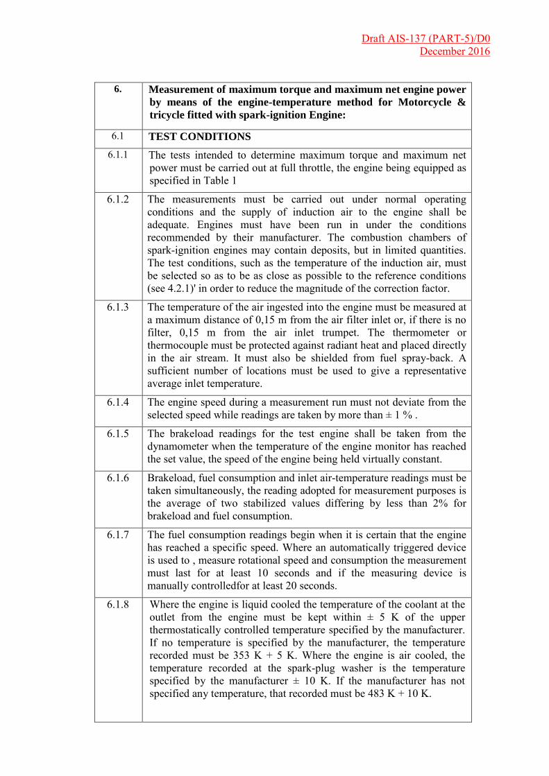
Draft AIS-137 (PART-5)/D0 December 2016
6. Measurement of maximum torque and maximum net engine power
by means of the engine-temperature method for Motorcycle &
tricycle fitted with spark-ignition Engine:
6.1 TEST CONDITIONS
6.1.1 The tests intended to determine maximum torque and maximum net power must be carried out at full throttle, the engine being equipped as specified in Table 1
6.1.2 The measurements must be carried out under normal operating conditions and the supply of induction air to the engine shall be adequate. Engines must have been run in under the conditions recommended by their manufacturer. The combustion chambers of spark-ignition engines may contain deposits, but in limited quantities. The test conditions, such as the temperature of the induction air, must be selected so as to be as close as possible to the reference conditions (see 4.2.1)' in order to reduce the magnitude of the correction factor.
6.1.3 The temperature of the air ingested into the engine must be measured at a maximum distance of 0,15 m from the air filter inlet or, if there is no filter, 0,15 m from the air inlet trumpet. The thermometer or thermocouple must be protected against radiant heat and placed directly in the air stream. It must also be shielded from fuel spray-back. A sufficient number of locations must be used to give a representative average inlet temperature.
6.1.4 The engine speed during a measurement run must not deviate from the selected speed while readings are taken by more than ± 1 % .
6.1.5 The brakeload readings for the test engine shall be taken from the dynamometer when the temperature of the engine monitor has reached the set value, the speed of the engine being held virtually constant.
6.1.6 Brakeload, fuel consumption and inlet air-temperature readings must be taken simultaneously, the reading adopted for measurement purposes is the average of two stabilized values differing by less than 2% for brakeload and fuel consumption.
6.1.7 The fuel consumption readings begin when it is certain that the engine has reached a specific speed. Where an automatically triggered device is used to , measure rotational speed and consumption the measurement must last for at least 10 seconds and if the measuring device is manually controlledfor at least 20 seconds.
6.1.8 Where the engine is liquid cooled the temperature of the coolant at the outlet from the engine must be kept within ± 5 K of the upper thermostatically controlled temperature specified by the manufacturer. If no temperature is specified by the manufacturer, the temperature recorded must be 353 K + 5 K. Where the engine is air cooled, the temperature recorded at the spark-plug washer is the temperature specified by the manufacturer ± 10 K. If the manufacturer has not specified any temperature, that recorded must be 483 K + 10 K.
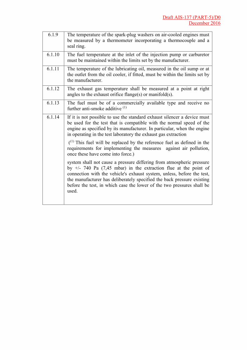
Draft AIS-137 (PART-5)/D0 December 2016
6.1.9 The temperature of the spark-plug washers on air-cooled engines must be measured by a thermometer incorporating a thermocouple and a seal ring.
6.1.10 The fuel temperature at the inlet of the injection pump or carburetor must be maintained within the limits set by the manufacturer.
6.1.11 The temperature of the lubricating oil, measured in the oil sump or at the outlet from the oil cooler, if fitted, must be within the limits set by the manufacturer.
6.1.12 The exhaust gas temperature shall be measured at a point at right angles to the exhaust orifice flange(s) or manifold(s).
6.1.13 The fuel must be of a commercially available type and receive no further anti-smoke additive (1)
6.1.14 If it is not possible to use the standard exhaust silencer a device must be used for the test that is compatible with the normal speed of the engine as specified by its manufacturer. In particular, when the engine in operating in the test laboratory the exhaust gas extraction
((1) This fuel will be replaced by the reference fuel as defined in the requirements for implementing the measures against air pollution, once these have come into force.)
system shall not cause a pressure differing from atmospheric pressure by +/- 740 Pa (7,45 mbar) in the extraction flue at the point of connection with the vehicle's exhaust system, unless, before the test, the manufacturer has deliberately specified the back pressure existing before the test, in which case the lower of the two pressures shall be used.

Draft AIS-137 (PART-5)/D0 December 2016
Appendix 6
Method for measuring Gross power of internal combustion engine
to be installed in agriculture & forestry tractors (A Category) and in
non-road mobile machinery (C Category) of vehicles.
1. Specifications and tests
1.1. General
The components liable to affect the power of the engine shall be so designed, constructed and assembled as to enable the engine in normal use, despite the vibrations to which it may be subjected, to comply with the provisions of this chapter.
1.2. Description of tests for internal combustion engines
1.2.1. The net power test shall consist of a run at full throttle for positive-ignition engines and at fixed full-load fuel injection pump setting for compression-ignition engines, the engine being equipped as specified in Table 1 of this Appendix.
1.2.2. Measurements shall be taken at a sufficient number of engine speeds to define correctly the power, torque and specific fuel consumption curves between the lowest and the highest engine speeds recommended by the manufacturer. This range of speeds must include the rotational speeds at which the engine produces its rated net power, its maximum power and its maximum torque.
1.2.3. The fuel used shall be the following: 1.2.3.1. For positive-ignition engines fuelled with petrol:
The fuel used shall be the reference fuel specified in chapter 7. 1.2.3.2. For positive-ignition engines fuelled with LPG:
The fuel used shall be the reference fuel specified in chapter 7. 1.2.3.3. For positive-ignition engines fuelled with natural gas:
The fuel used shall be the reference fuel specified in chapter 7. 1.2.3.4. For compression-ignition engines:
The fuel used shall be the reference fuel specified in chapter 7.
The choice of the test fuel shall be made based on the exhaust limit values that the engine type or the engine family is intended to comply with. Based on the power bands described in the Chapter setting uniform provisions concerning the approval of compression ignition (C.I.) engines to be installed in agricultural and forestry tractors and in non-road mobile machinery with regard to the emissions of pollutants by the engine, the reference fuel shall be selected as follows: 1 "Wobbe Index (lower Wl; or upper Wu)" means the ratio of the corresponding calorific value of a gas per unit volume and the square root of its relative density under the same reference conditions:
W H xgas air gas /
Optionally, the reference fuel specified in chapter 7 may be used
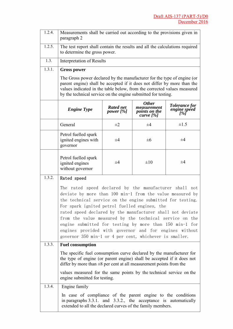
Draft AIS-137 (PART-5)/D0 December 2016
1.2.4. Measurements shall be carried out according to the provisions given in
paragraph 2
1.2.5. The test report shall contain the results and all the calculations required to determine the gross power.
1.3. Interpretation of Results
1.3.1. Gross power
The Gross power declared by the manufacturer for the type of engine (or parent engine) shall be accepted if it does not differ by more than the values indicated in the table below, from the corrected values measured by the technical service on the engine submitted for testing.
Engine Type Rated net
power [%]
Other measurement points on the
curve [%]
Tolerance for engine speed
[%]
General ±2 ±4 ±1.5
Petrol fuelled spark ignited engines with governor
±4 ±6 ±4
Petrol fuelled spark ignited engines without governor
±4 ±10 ±4
1.3.2. Rated speed
The rated speed declared by the manufacturer shall not
deviate by more than 100 min-1 from the value measured by
the technical service on the engine submitted for testing.
For spark ignited petrol fuelled engines, the
rated speed declared by the manufacturer shall not deviate
from the value measured by the technical service on the
engine submitted for testing by more than 150 min-1 for
engines provided with governor and for engines without
governor 350 min-1 or 4 per cent, whichever is smaller.
1.3.3. Fuel consumption
The specific fuel consumption curve declared by the manufacturer for the type of engine (or parent engine) shall be accepted if it does not differ by more than ±8 per cent at all measurement points from the
values measured for the same points by the technical service on the engine submitted for testing.
1.3.4. Engine family
In case of compliance of the parent engine to the conditions in paragraphs 3.3.1. and 3.3.2., the acceptance is automatically extended to all the declared curves of the family members.

Draft AIS-137 (PART-5)/D0 December 2016
2 Method for measuring internal combustion engine Gross power:
2.1. These provisions apply to the method for determining the power curve at full load of an internal combustion engine operated under intermittent speed as a function of engine speed and the rated speed and rated gross power of an internal combustion engine under constant speed.
2.2 Test conditions
2.2.1. The engine shall have been run-in according to the manufacturer's
recommendations.
2.2.2. If the power measurement can be carried out only on an engine with
the gearbox mounted, the efficiency of the gearbox shall be taken into account.
2.2.3. Auxiliaries and equipment
2.2.3.1. Auxiliaries and equipment to be fitted
During the test, the auxiliaries necessary for the engine operation in the intended application (as listed in Table 1) shall be installed on the test bench as far as possible in the same position as in the intended application.
2.2.3.2. Auxiliaries and equipment to be removed
Certain auxiliaries whose definition is linked with the operation of the machine and which may be mounted on the engine shall be removed for the test. The following non-exhaustive list is given as a sample:
(i) Air compressor for brakes
(ii) Power steering compressor
(iii) Suspension compressor
(iv) Air-conditioning system
Where auxiliaries cannot be removed, the power they absorb in the unloaded condition may be determined and added to the measured engine power (see note h of Table 1). If this value is greater than 3 per cent of the maximum power at the test speed it may verified by the test authority.
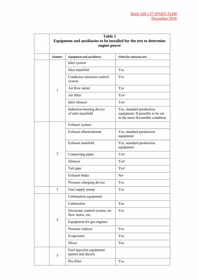
Draft AIS-137 (PART-5)/D0 December 2016
Table 1
Equipment and auxiliaries to be installed for the test to determine
engine power
Number Equipment and auxiliaries Fitted for emission test
1
Inlet system
Inlet manifold Yes
Crankcase emission control system
Yes
Air flow meter Yes
Air filter Yesa
Inlet silencer Yesa
Induction-heating device of inlet manifold
Yes, standard production equipment. If possible to be set in the most favourable condition
2
Exhaust system
Exhaust aftertreatment Yes, standard production equipment
Exhaust manifold Yes, standard production equipment
Connecting pipes Yesb
Silencer Yesb
Tail pipe Yesb
Exhaust brake Noc
Pressure charging device Yes
3 Fuel supply pump Yes
4
Carburation equipment
Carburettor Yes
Electronic control system, air flow meter, etc.
Yes
Equipment for gas engines
Pressure reducer Yes
Evaporator Yes
Mixer Yes
5 Fuel injection equipment (petrol and diesel)
Pre-filter Yes

Draft AIS-137 (PART-5)/D0 December 2016
Filter Yes
Pump Yes
High-pressure pipe Yes
Injector Yes
Electronic control system, sensors, etc.
Yes
Governor/control system Yes
Automatic full-load stop for the control rack depending on atmospheric conditions
Yes
6 Liquid-cooling equipment
Radiator No
Fan No
Fan cowl No
Water pump Yese
Thermostat Yesf
7 Air cooling
Cowl Nog
Fan or Blower Nog
Temperature-regulating device
No
8 Electrical equipment
Generator Yesh
Spark distribution system Yes
Coil or coils Yes
Wiring Yes
Spark plugs Yes
Electronic control system including knock sensor/spark retard system
Yes
9 Pressure charging equipment
Charge air cooler Yes
Coolant pump or fan (engine-driven)
Nog
Coolant flow control device Yes
Auxiliary test-bed fan Yes, if necessary
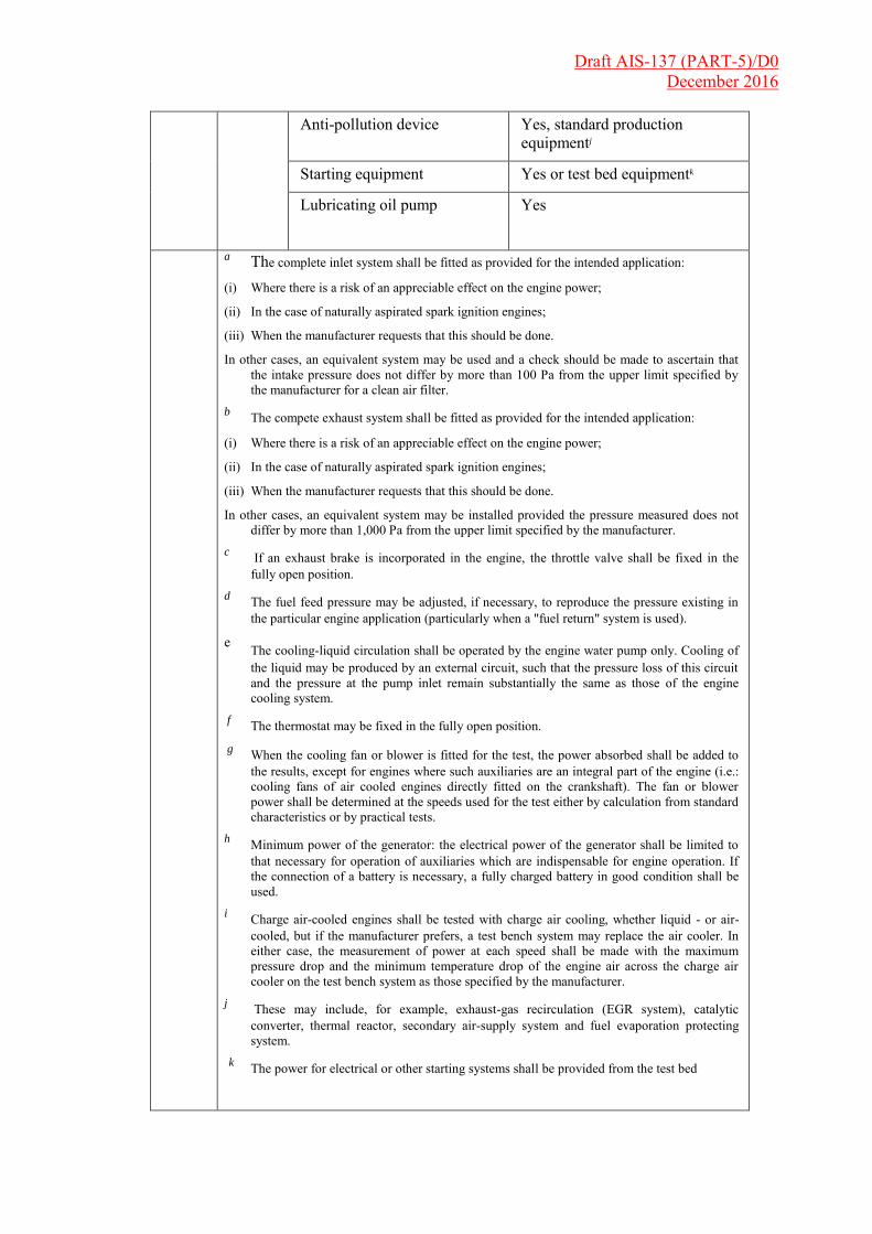
Draft AIS-137 (PART-5)/D0 December 2016
Anti-pollution device Yes, standard production equipmentj
Starting equipment Yes or test bed equipmentk
Lubricating oil pump Yes
a The complete inlet system shall be fitted as provided for the intended application:
(i) Where there is a risk of an appreciable effect on the engine power;
(ii) In the case of naturally aspirated spark ignition engines;
(iii) When the manufacturer requests that this should be done.
In other cases, an equivalent system may be used and a check should be made to ascertain that the intake pressure does not differ by more than 100 Pa from the upper limit specified by the manufacturer for a clean air filter.
b The compete exhaust system shall be fitted as provided for the intended application:
(i) Where there is a risk of an appreciable effect on the engine power;
(ii) In the case of naturally aspirated spark ignition engines;
(iii) When the manufacturer requests that this should be done.
In other cases, an equivalent system may be installed provided the pressure measured does not differ by more than 1,000 Pa from the upper limit specified by the manufacturer.
c If an exhaust brake is incorporated in the engine, the throttle valve shall be fixed in the fully open position.
d The fuel feed pressure may be adjusted, if necessary, to reproduce the pressure existing in the particular engine application (particularly when a "fuel return" system is used).
e The cooling-liquid circulation shall be operated by the engine water pump only. Cooling of the liquid may be produced by an external circuit, such that the pressure loss of this circuit and the pressure at the pump inlet remain substantially the same as those of the engine cooling system.
f The thermostat may be fixed in the fully open position. g When the cooling fan or blower is fitted for the test, the power absorbed shall be added to
the results, except for engines where such auxiliaries are an integral part of the engine (i.e.: cooling fans of air cooled engines directly fitted on the crankshaft). The fan or blower power shall be determined at the speeds used for the test either by calculation from standard characteristics or by practical tests.
h Minimum power of the generator: the electrical power of the generator shall be limited to that necessary for operation of auxiliaries which are indispensable for engine operation. If the connection of a battery is necessary, a fully charged battery in good condition shall be used.
i Charge air-cooled engines shall be tested with charge air cooling, whether liquid - or air-cooled, but if the manufacturer prefers, a test bench system may replace the air cooler. In either case, the measurement of power at each speed shall be made with the maximum pressure drop and the minimum temperature drop of the engine air across the charge air cooler on the test bench system as those specified by the manufacturer.
j These may include, for example, exhaust-gas recirculation (EGR system), catalytic converter, thermal reactor, secondary air-supply system and fuel evaporation protecting system.
k The power for electrical or other starting systems shall be provided from the test bed
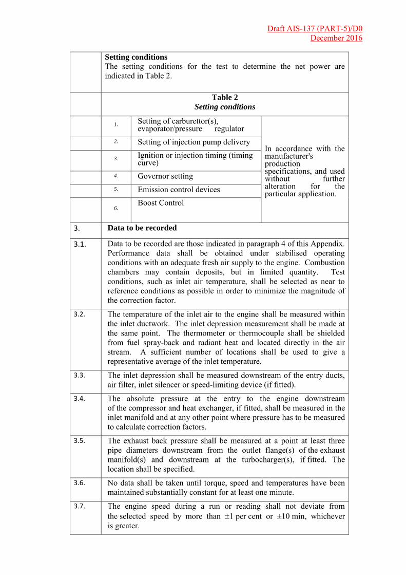
Draft AIS-137 (PART-5)/D0 December 2016
Setting conditions
The setting conditions for the test to determine the net power are indicated in Table 2.
Table 2
Setting conditions
1. Setting of carburettor(s),
evaporator/pressure regulator
In accordance with the manufacturer's production specifications, and used without further alteration for the particular application.
2. Setting of injection pump delivery system
3. Ignition or injection timing (timing curve)
4. Governor setting 5. Emission control devices
6. Boost Control
3. Data to be recorded
3.1. Data to be recorded are those indicated in paragraph 4 of this Appendix. Performance data shall be obtained under stabilised operating conditions with an adequate fresh air supply to the engine. Combustion chambers may contain deposits, but in limited quantity. Test conditions, such as inlet air temperature, shall be selected as near to reference conditions as possible in order to minimize the magnitude of the correction factor.
3.2. The temperature of the inlet air to the engine shall be measured within the inlet ductwork. The inlet depression measurement shall be made at the same point. The thermometer or thermocouple shall be shielded from fuel spray-back and radiant heat and located directly in the air stream. A sufficient number of locations shall be used to give a representative average of the inlet temperature.
3.3. The inlet depression shall be measured downstream of the entry ducts, air filter, inlet silencer or speed-limiting device (if fitted).
3.4. The absolute pressure at the entry to the engine downstream of the compressor and heat exchanger, if fitted, shall be measured in the inlet manifold and at any other point where pressure has to be measured to calculate correction factors.
3.5. The exhaust back pressure shall be measured at a point at least three pipe diameters downstream from the outlet flange(s) of the exhaust manifold(s) and downstream at the turbocharger(s), if fitted. The location shall be specified.
3.6. No data shall be taken until torque, speed and temperatures have been maintained substantially constant for at least one minute.
3.7. The engine speed during a run or reading shall not deviate from the selected speed by more than 1 per cent or ±10 min, whichever is greater.
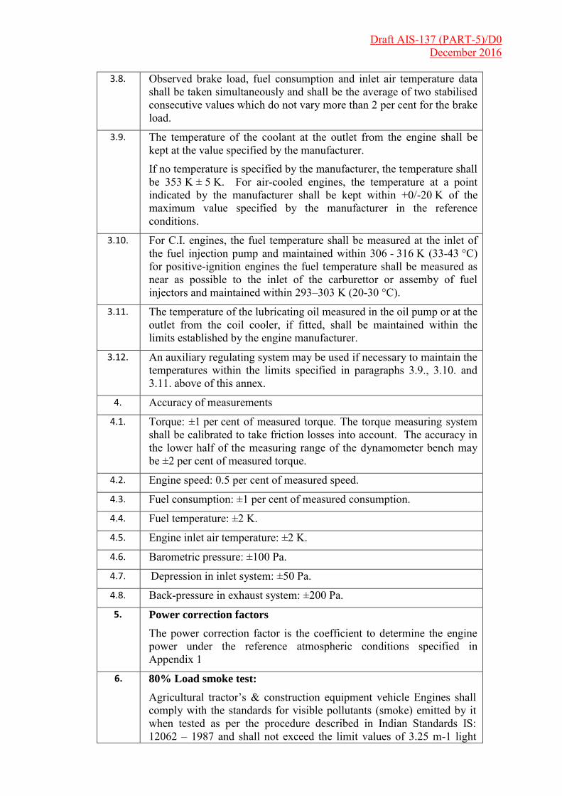
Draft AIS-137 (PART-5)/D0 December 2016
3.8. Observed brake load, fuel consumption and inlet air temperature data shall be taken simultaneously and shall be the average of two stabilised consecutive values which do not vary more than 2 per cent for the brake load.
3.9. The temperature of the coolant at the outlet from the engine shall be kept at the value specified by the manufacturer.
If no temperature is specified by the manufacturer, the temperature shall be 353 K ± 5 K. For air-cooled engines, the temperature at a point indicated by the manufacturer shall be kept within +0/-20 K of the maximum value specified by the manufacturer in the reference conditions.
3.10. For C.I. engines, the fuel temperature shall be measured at the inlet of the fuel injection pump and maintained within 306 - 316 K (33-43 °C) for positive-ignition engines the fuel temperature shall be measured as near as possible to the inlet of the carburettor or assemby of fuel injectors and maintained within 293–303 K (20-30 °C).
3.11. The temperature of the lubricating oil measured in the oil pump or at the outlet from the coil cooler, if fitted, shall be maintained within the limits established by the engine manufacturer.
3.12. An auxiliary regulating system may be used if necessary to maintain the temperatures within the limits specified in paragraphs 3.9., 3.10. and 3.11. above of this annex.
4. Accuracy of measurements
4.1. Torque: ±1 per cent of measured torque. The torque measuring system shall be calibrated to take friction losses into account. The accuracy in the lower half of the measuring range of the dynamometer bench may be ±2 per cent of measured torque.
4.2. Engine speed: 0.5 per cent of measured speed.
4.3. Fuel consumption: ±1 per cent of measured consumption.
4.4. Fuel temperature: ±2 K.
4.5. Engine inlet air temperature: ±2 K.
4.6. Barometric pressure: ±100 Pa.
4.7. Depression in inlet system: ±50 Pa.
4.8. Back-pressure in exhaust system: ±200 Pa.
5. Power correction factors
The power correction factor is the coefficient to determine the engine power under the reference atmospheric conditions specified in Appendix 1
6. 80% Load smoke test:
Agricultural tractor’s & construction equipment vehicle Engines shall comply with the standards for visible pollutants (smoke) emitted by it when tested as per the procedure described in Indian Standards IS: 12062 – 1987 and shall not exceed the limit values of 3.25 m-1 light

Draft AIS-137 (PART-5)/D0 December 2016
absorption co-efficient (75 H.S.U.) when tested on engine dynamometer at 80% load at six equally spaced speeds
between
55% of maximum power speed as declared by the manufacturer or 1000
rpm whichever is higher
And
Maximum Power speed as declared by the manufacturer.
Agricultural tractor & construction equipment vehicle & Engine Manufacturer shall declare Air Intake depression & Exhaust Back Pressure jointly for all vehicle models with same engine family. At the time of approval of vehicle model, AID & EBP shall be confirmed by Test Agency that they are within the declared specifications.
7. Maximum Gross Power measurement tolerances for A & C
Category (C.I. Engine) of vehicles:
For Type Approval :
For single cylinder engines, ±10% at maximum power point including all other measured speeds.
For all other engines, ±5% at rated speed and all other measured speeds.
For Conformity of Production :
At maximum power point by ±10% for single cylinder engines and –5%+8% for all other engines.
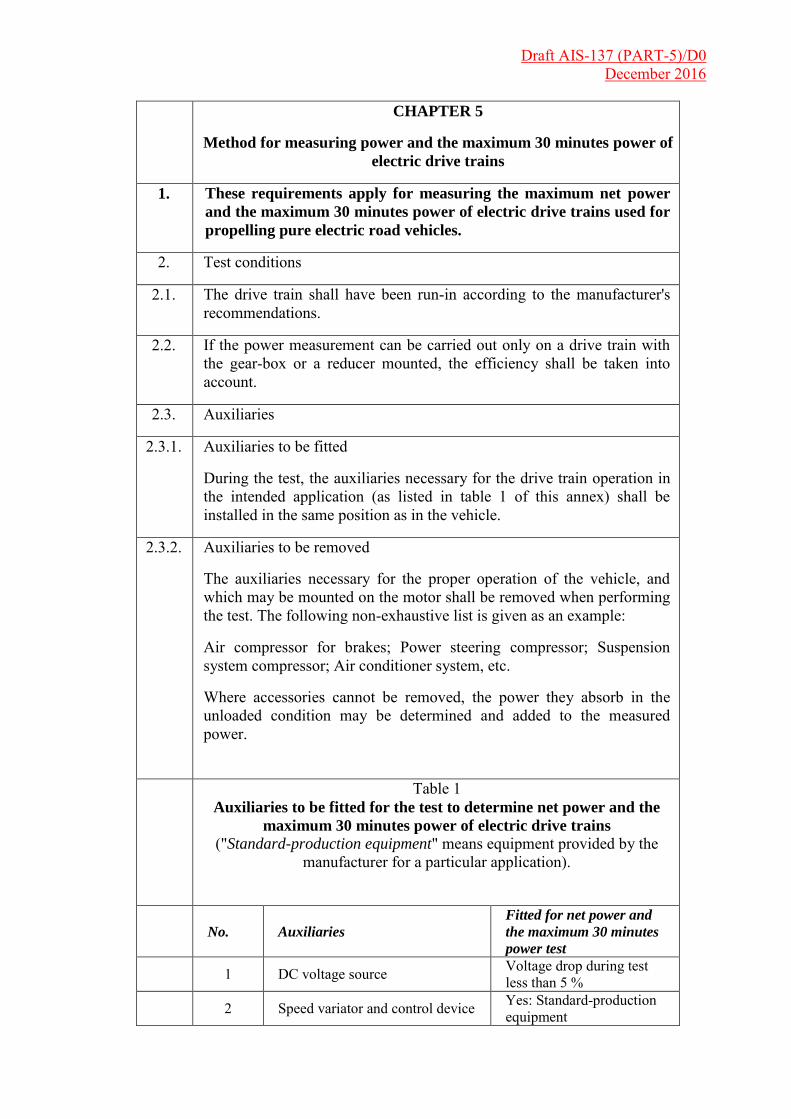
Draft AIS-137 (PART-5)/D0 December 2016
CHAPTER 5
Method for measuring power and the maximum 30 minutes power of
electric drive trains
1. These requirements apply for measuring the maximum net power
and the maximum 30 minutes power of electric drive trains used for
propelling pure electric road vehicles.
2. Test conditions
2.1. The drive train shall have been run-in according to the manufacturer's recommendations.
2.2. If the power measurement can be carried out only on a drive train with the gear-box or a reducer mounted, the efficiency shall be taken into account.
2.3. Auxiliaries
2.3.1. Auxiliaries to be fitted
During the test, the auxiliaries necessary for the drive train operation in the intended application (as listed in table 1 of this annex) shall be installed in the same position as in the vehicle.
2.3.2. Auxiliaries to be removed
The auxiliaries necessary for the proper operation of the vehicle, and which may be mounted on the motor shall be removed when performing the test. The following non-exhaustive list is given as an example:
Air compressor for brakes; Power steering compressor; Suspension system compressor; Air conditioner system, etc.
Where accessories cannot be removed, the power they absorb in the unloaded condition may be determined and added to the measured power.
Table 1 Auxiliaries to be fitted for the test to determine net power and the
maximum 30 minutes power of electric drive trains
("Standard-production equipment" means equipment provided by the manufacturer for a particular application).
No. Auxiliaries
Fitted for net power and
the maximum 30 minutes
power test
1 DC voltage source Voltage drop during test less than 5 %
2 Speed variator and control device Yes: Standard-production equipment
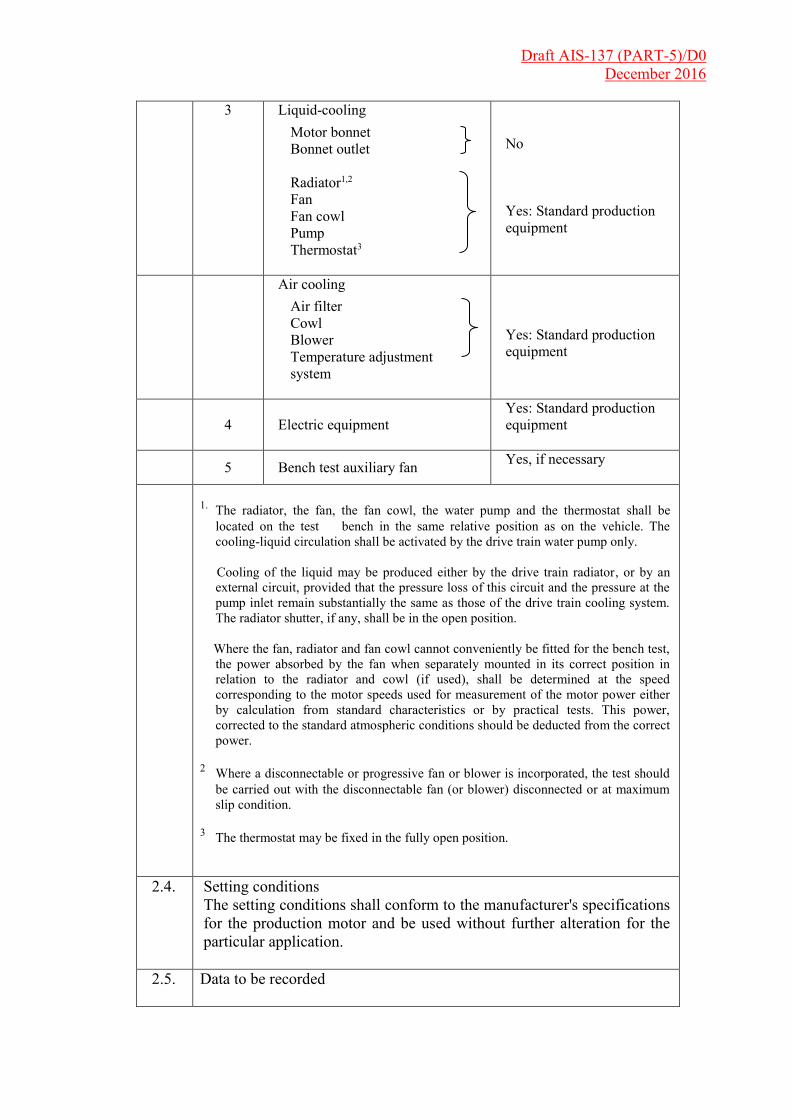
Draft AIS-137 (PART-5)/D0 December 2016
3 Liquid-cooling
Motor bonnet Bonnet outlet
Radiator1,2 Fan Fan cowl Pump Thermostat3
No Yes: Standard production equipment
Air cooling Air filter Cowl Blower Temperature adjustment system
Yes: Standard production equipment
4 Electric equipment
Yes: Standard production equipment
5 Bench test auxiliary fan Yes, if necessary
1. The radiator, the fan, the fan cowl, the water pump and the thermostat shall be located on the test bench in the same relative position as on the vehicle. The cooling-liquid circulation shall be activated by the drive train water pump only.
Cooling of the liquid may be produced either by the drive train radiator, or by an
external circuit, provided that the pressure loss of this circuit and the pressure at the pump inlet remain substantially the same as those of the drive train cooling system. The radiator shutter, if any, shall be in the open position.
Where the fan, radiator and fan cowl cannot conveniently be fitted for the bench test,
the power absorbed by the fan when separately mounted in its correct position in relation to the radiator and cowl (if used), shall be determined at the speed corresponding to the motor speeds used for measurement of the motor power either by calculation from standard characteristics or by practical tests. This power, corrected to the standard atmospheric conditions should be deducted from the correct power.
2 Where a disconnectable or progressive fan or blower is incorporated, the test should be carried out with the disconnectable fan (or blower) disconnected or at maximum slip condition.
3 The thermostat may be fixed in the fully open position.
2.4. Setting conditions
The setting conditions shall conform to the manufacturer's specifications for the production motor and be used without further alteration for the particular application.
2.5. Data to be recorded
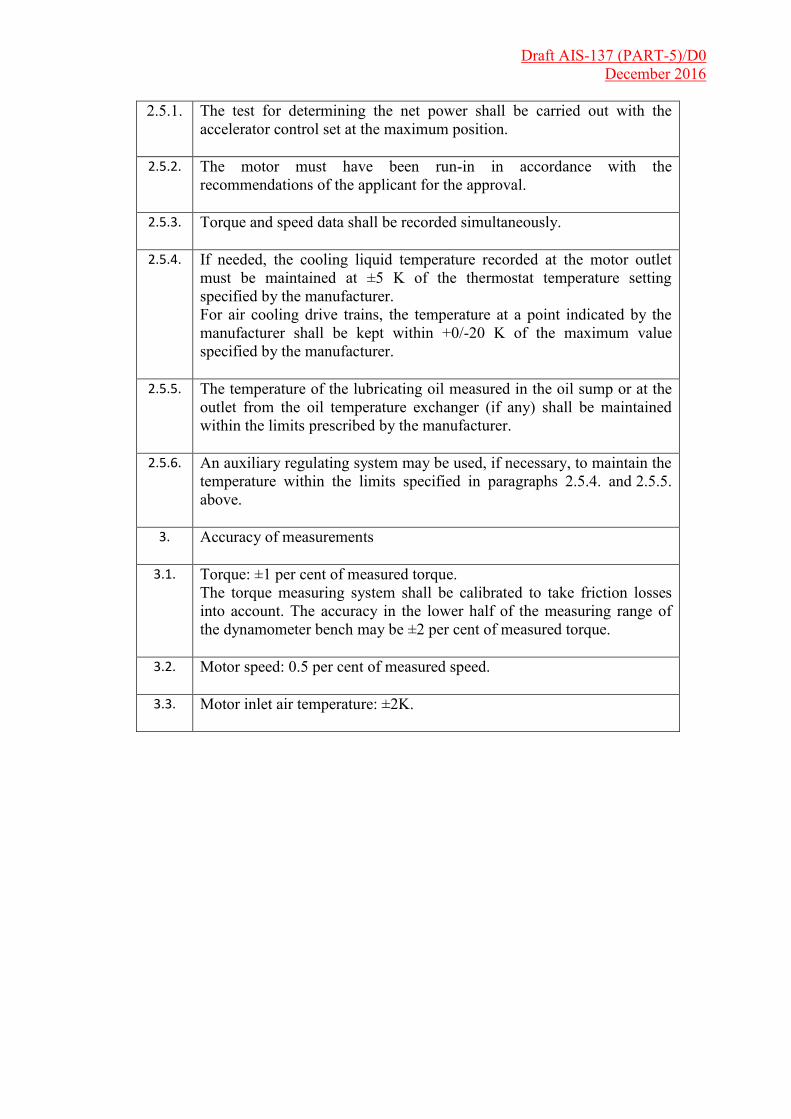
Draft AIS-137 (PART-5)/D0 December 2016
2.5.1. The test for determining the net power shall be carried out with the accelerator control set at the maximum position.
2.5.2. The motor must have been run-in in accordance with the recommendations of the applicant for the approval.
2.5.3. Torque and speed data shall be recorded simultaneously.
2.5.4. If needed, the cooling liquid temperature recorded at the motor outlet must be maintained at ±5 K of the thermostat temperature setting specified by the manufacturer. For air cooling drive trains, the temperature at a point indicated by the manufacturer shall be kept within +0/-20 K of the maximum value specified by the manufacturer.
2.5.5. The temperature of the lubricating oil measured in the oil sump or at the outlet from the oil temperature exchanger (if any) shall be maintained within the limits prescribed by the manufacturer.
2.5.6. An auxiliary regulating system may be used, if necessary, to maintain the temperature within the limits specified in paragraphs 2.5.4. and 2.5.5. above.
3. Accuracy of measurements
3.1. Torque: ±1 per cent of measured torque. The torque measuring system shall be calibrated to take friction losses into account. The accuracy in the lower half of the measuring range of the dynamometer bench may be ±2 per cent of measured torque.
3.2. Motor speed: 0.5 per cent of measured speed.
3.3. Motor inlet air temperature: ±2K.
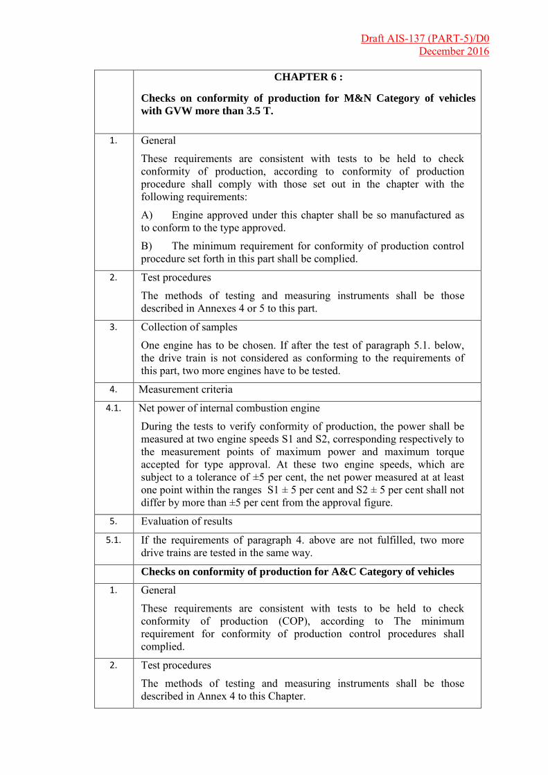
Draft AIS-137 (PART-5)/D0 December 2016
CHAPTER 6 :
Checks on conformity of production for M&N Category of vehicles
with GVW more than 3.5 T.
1. General
These requirements are consistent with tests to be held to check conformity of production, according to conformity of production procedure shall comply with those set out in the chapter with the following requirements:
A) Engine approved under this chapter shall be so manufactured as to conform to the type approved.
B) The minimum requirement for conformity of production control procedure set forth in this part shall be complied.
2. Test procedures
The methods of testing and measuring instruments shall be those described in Annexes 4 or 5 to this part.
3. Collection of samples
One engine has to be chosen. If after the test of paragraph 5.1. below, the drive train is not considered as conforming to the requirements of this part, two more engines have to be tested.
4. Measurement criteria
4.1. Net power of internal combustion engine
During the tests to verify conformity of production, the power shall be measured at two engine speeds S1 and S2, corresponding respectively to the measurement points of maximum power and maximum torque accepted for type approval. At these two engine speeds, which are subject to a tolerance of ±5 per cent, the net power measured at at least one point within the ranges S1 ± 5 per cent and S2 ± 5 per cent shall not differ by more than ±5 per cent from the approval figure.
5. Evaluation of results
5.1. If the requirements of paragraph 4. above are not fulfilled, two more drive trains are tested in the same way.
Checks on conformity of production for A&C Category of vehicles 1. General
These requirements are consistent with tests to be held to check conformity of production (COP), according to The minimum requirement for conformity of production control procedures shall complied.
2. Test procedures
The methods of testing and measuring instruments shall be those described in Annex 4 to this Chapter.
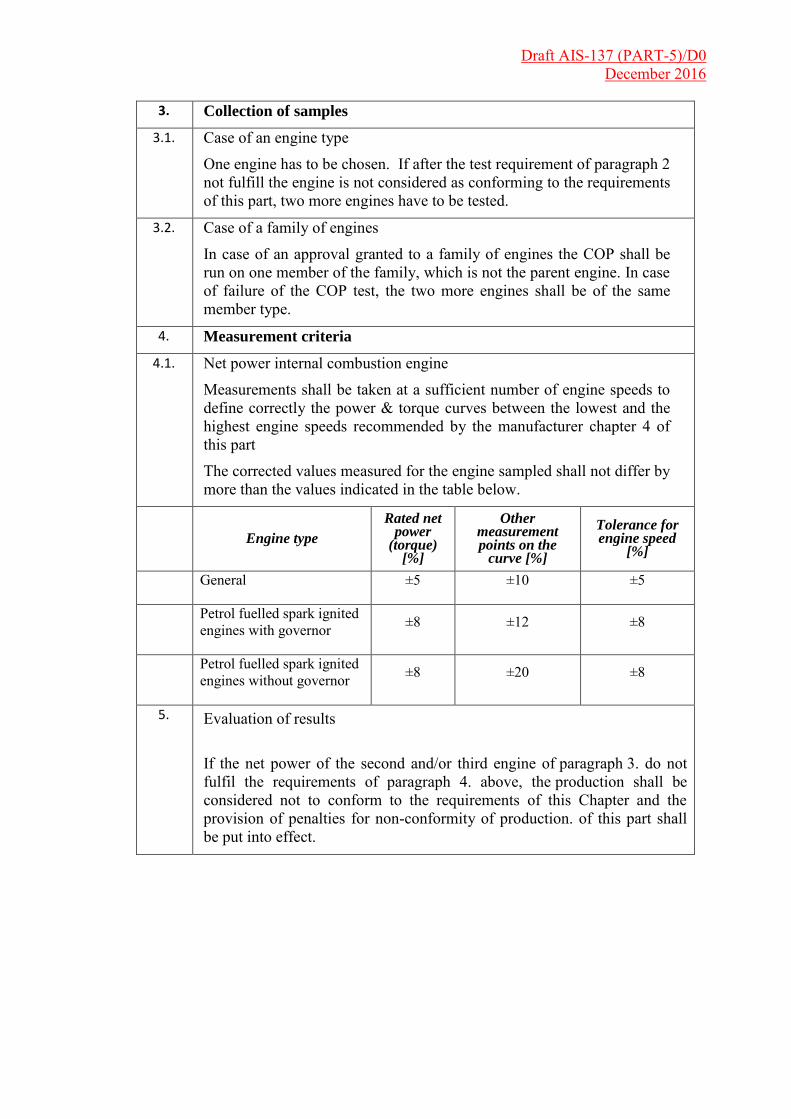
Draft AIS-137 (PART-5)/D0 December 2016
3. Collection of samples
3.1. Case of an engine type
One engine has to be chosen. If after the test requirement of paragraph 2 not fulfill the engine is not considered as conforming to the requirements of this part, two more engines have to be tested.
3.2. Case of a family of engines
In case of an approval granted to a family of engines the COP shall be run on one member of the family, which is not the parent engine. In case of failure of the COP test, the two more engines shall be of the same member type.
4. Measurement criteria
4.1. Net power internal combustion engine
Measurements shall be taken at a sufficient number of engine speeds to define correctly the power & torque curves between the lowest and the highest engine speeds recommended by the manufacturer chapter 4 of this part
The corrected values measured for the engine sampled shall not differ by more than the values indicated in the table below.
Engine type
Rated net power
(torque) [%]
Other measurement points on the
curve [%]
Tolerance for engine speed
[%]
General ±5 ±10 ±5
Petrol fuelled spark ignited engines with governor ±8 ±12 ±8
Petrol fuelled spark ignited engines without governor ±8 ±20 ±8
5. Evaluation of results If the net power of the second and/or third engine of paragraph 3. do not fulfil the requirements of paragraph 4. above, the production shall be considered not to conform to the requirements of this Chapter and the provision of penalties for non-conformity of production. of this part shall be put into effect.

Draft AIS-137 (PART-5)/D0 December 2016
CHAPTER 7 :
Reference fuels
The reference fuel shall be as per CMVR notification.