Automobile Engineering
45
LABORATORY MANUAL AUTOMOBILE ENGINEERING ME- 314-F NARESH KUMAR (BRCM-BAHAL)
description
Automobile Engineering
Transcript of Automobile Engineering

LABORATORY MANUAL
AUTOMOBILE ENGINEERING
ME- 314-F
NARESH KUMAR
(BRCM-BAHAL)

LIST OF THE EXPERIMENTS
S.
No. Name of the Experiment Page No
From To
1.
To study and prepare report on the constructional details, working principles and
operation of the following Automotive Engine Systems & Sub Systems.
(a) Multi-cylinder : Diesel and Petrol Engines.
(b) Engine cooling & lubricating Systems.
(c) Engine starting Systems.
(d) Contact Point & Electronic Ignition Systems
2.
To study and prepare report on the constructional details, working principles and
operation of the following Fuels supply systems:
(a) Carburetors
(b) Diesel Fuel Injection Systems
(c) Gasoline Fuel Injection Systems.
3.
To study and prepare report on the constructional details, working principles and
operation of the following Automotive Clutches.
(a) Coil-Spring Clutch
(b) Diaphragm – Spring Clutch.
(c) Double Disk Clutch.
4.
To study and prepare report on the constructional details, working principles and
operation of the following Automotive Transmission systems.
(a) Synchromesh – Four speed Range.
(b) Transaxle with Dual Speed Range.
(c) Four Wheel Drive and Transfer Case.
(d) Steering Column and Floor – Shift levers.
5.
To study and prepare report on the constructional details, working principles and
operation of the following Automotive Drive Lines & Differentials.
(a) Rear Wheel Drive Line.
(b) Front Wheel Drive Line.
(c) Differentials, Drive Axles and Four Wheel Drive Line

6.
To study and prepare report on the constructional details, working principles and
operation of the following Automotive Suspension Systems.
(a) Front Suspension System.
(b) Rear Suspension System.
7.
To study and prepare report on the constructional details, working principles and
operation of the following Automotive Steering Systems.
(a) Manual Steering Systems, e.g. Pitman –arm steering, Rack & Pinion steering.
(b) Power steering Systems, e.g. Rack and Pinion Power Steering System.
(c) Steering Wheels and Columns e.g. Tilt & Telescopic steering Wheels,
Collapsible Steering Columns.
8. To study and prepare report on the constructional details, working principles and
operation of the following Automotive Tyres & wheels.
(a) Various Types of Bias & Radial Tyres.
(b) Various Types of wheels.
9.
To study and prepare report on the constructional details, working principles and
operation of the Automotive Brake systems.
(a) Hydraulic & Pneumatic Brake systems.
(b) Drum Brake System.
(c) Disk Brake System.
(d) Antilock Brake System.
(e) System Packing & Other Brakes.
10.
To study and prepare report on the constructional details, working principles and
operation of Automotive Emission / Pollution control systems.
NARESH KUMAR
(BRCM-BAHAL)

EXPERIMENT 1
Aim: To study and prepare report on the constructional details, working principles and
operation of the Automotive Engine Systems & Sub Systems.
Apparatus: Models of
(a) Multi-cylinder : Diesel and Petrol Engines.
(b) Engine cooling & lubricating Systems.
(c) Engine starting Systems.
(d) Contact Point & Electronic Ignition Systems.
Theory:
(a) Multi-cylinder: Diesel and Petrol Engines.
Both are internal combustion engines. The difference is that Diesel engine is CI
(compression Ignition) and petrol is SI (Spark Ignition). In a petrol engine spark is used to
initiate the ignition of the petrol air mixture. In a diesel engine the Air is compressed to 21
times its normal volume (Approx) and then fuel is injected into the Cylinder head/ or piston,
due to the high compression the temperature rises and as fuel is injected it ignites.
Both diesel and petrol engines may be 2 stroke or 4 stroke engines. In 2 stroke cycle
engine: The engine revolves once (two strokes of the piston, one down, one up) for a complete
cycle of the engine. Whereas in 4-stroke cycle engine: Each complete cycle of the engine
involves four strokes of the piston, a down, an up, a down, and an up stroke for each complete
cycle of the engine (which is two revolutions of the engine).
A single cylinder four-stroke piston engine spends three quarters of its running time
exhausting burned gas, drawing in fresh mixture and compressing it. On only one of the four
strokes the power stroke is any energy produced and this makes the output of a single cylinder
four stroke engine very uneven. This can be smoothed out if more cylinders, with their pistons
driving a common crank shaft, are used. A twin-cylinder four stroke, for instance, will produce
one power stroke for each revolution of the crank shaft, instead of every other revolution as on
a single cylinder engine. If the engine has four cylinders it produces one power stroke for each
half-turn of the crankshaft and at no time is the crankshaft free wheeling’ on one of the three
passive strokes. Even better results can be obtained using six cylinders, as the power strokes
can be made to overlap, so that the crankshaft receives a fresh impulse before the previous
power stroke has died away on an in-line six-cylinder engine the crankshaft receives three
power impulses each revolution. In theory, the more cylinders you can use to drive the crank-
shaft, the smoother the power output, and 8 and 12 cylinder engines are used on some of the
more expensive cars. A large number of cylinders can pose practical problems. An engine with
eight cylinders in a straight line for instance would have a very long crank- shaft which would
tend to twist and be more likely to break at higher engine speeds. The car would also need a
long bonnet to enclose the engine. So in the interests of crank- shaft rigidity and compactness, 8

and 12 cylinder engines have their cylinders arranged in a V, with two cylinder heads and a
common crankshaft. There are also V-6 and V-4 cylinder engines.
Fig: In line engine or 6 cylinder engine
Fig: V8 Engine
The construction, working principle and operation of multi cylinder engines is same as
single cylinder diesel and petrol engines .

(b) Engine cooling & lubricating Systems.
Engine Cooling Systems: The cooling system removes excess heat to keep the inside of the
engine at an efficient temperature, about 200oF (94
oC). There are two types of cooling systems
found on automotives, they are liquid cooling system and air cooling system.
Construction, Working Principle and Operation of Air Cooling System: The air cooling system will have metal FINS on the outer perimeter of the engine. The heat is
transferred from the engine, through these fins, into the atmosphere.
Fig: Air Cooling System
Construction, Working Principle and Operation of Liquid Cooling System: The cooling system is made up of the passages inside the engine block and heads, a water pump
to circulate the coolant, a thermostat to control the temperature of the coolant, a radiator to cool
the coolant, a radiator cap to control the pressure in the system, and some plumbing consisting
of interconnecting hoses to transfer the coolant from the engine to radiator and also to the car's
heater system where hot coolant is used to warm up the vehicle's interior on a cold day.
A cooling system works by sending a liquid coolant through passages in the engine block and
heads. As the coolant flows through these passages, it picks up heat from the engine. The
heated fluid then makes its way through a rubber hose to the radiator in the front of the car. As
it flows through the thin tubes in the radiator, the hot liquid is cooled by the air stream entering
the engine compartment from the grill in front of the car. Once the fluid is cooled, it returns to
the engine to absorb more heat. The water pump has the job of keeping the fluid moving
through this system of plumbing and hidden passages. A thermostat is placed between the
engine and the radiator to make sure that the coolant stays above a certain preset temperature.
If the coolant temperature falls below this temperature, the thermostat blocks the coolant flow
to the radiator, forcing the fluid instead through a bypass directly back to the engine. The
coolant will continue to circulate like this until it reaches the design temperature, at which

point, the thermostat will open a valve and allow the coolant back through the radiator. In order
to prevent the coolant from boiling, the cooling system is designed to be pressurized. Under
pressure, the boiling point of the coolant is raised considerably. However, too much pressure
will cause hoses and other parts to burst, so a system is needed to relieve pressure if it exceeds
a certain point. The job of maintaining the pressure in the cooling system belongs to the
radiator cap. The cap is designed to release pressure if it reaches the specified upper limit that
the system was designed to handle. Prior to the '70s, the cap would release this extra pressure
to the pavement. Since then, a system was added to capture any released fluid and store it
temporarily in a reserve tank. This fluid would then return to the cooling system after the
engine cooled down. This is what is called a closed cooling system.
Fig: Liquid Cooling System
Engine Lubricating Systems: The engine lubrication system includes the lubricating oil, oil
pump, oil filter and the oil passages. Oil lubrication provides a barrier between rotating engine
parts to prevent damage by friction. The engine oil provides a method of cooling engine parts
that are not cooled by the engine cooling system. Engine oil helps to protect engine components
from corrosion by neutralizing harmful chemicals that are the by-product of combustion.
Construction, Working Principle and Operation of Lubricating System: To protect moving parts and reduce friction, automotive engine oil provides a barrier between
the rotating or moving engine components. Ideally, a film of oil should exist between moving
components. This is called full film lubrication. In order to achieve full film lubrication, a
constant supply of clean oil is required. The engine oil system constantly filters and circulates
engine oil to ensure that all components are protected. The engine oil is stored in the crankcase.
Most engines hold between 4 to 6 quarts of oil. The engine oil pump pressurizes and circulates
the engine oil. The oil will flow from the pump to the oil filter, where it is cleaned. The cleaned

engine oil then moves through passages, into the crankshaft where it circulates through the
engine bearings. The crankshaft has passages bored into it that allows oil to travel to all the
bearing surfaces. The cylinder walls and pistons are lubricated by the oil that is thrown from
the crankshaft as it rotates. This is sometimes referred to as splash lubrication. Engine oil will
leave the crankshaft, usually at a passage in one of the main bearings and is fed to the camshaft
and lifters. On some overhead valve engines, oil will travel through the pushrods up to the
valve train to lubricate the rocker arms. Other designs use a passage to feed oil through a rocker
arm shaft to achieve the same purpose. The oil then returns to the crankcase by return holes in
the cylinder heads. It is then picked up by the oil pump to be circulated again.
Fig: Engine Lubrication System
(c) Engine starting Systems: The "starting system", the heart of the electrical system in the
engine. The starting system converts electrical energy from the batteries into mechanical
energy to turn the engine over.
Construction, Working Principle and Operation of Engine starting System: Engine
starting system, begins with the Battery. The key is inserted into the Ignition Switch and then
turned to the start position. A small amount of current then passes through the Neutral Safety
Switch to a Starter Relay or Starter Solenoid which allows high current to flow through the
Battery Cables to the Starter Motor. The starter motor then cranks the engine so that the piston,
moving downward, can create a suction that will draw a Fuel/Air mixture into the cylinder,

where a spark created by the Ignition System will ignite this mixture. If the Compression in the
engine is high enough and all this happens at the right Time, the engine will start.
The starting system has five main components: the ignition switch or start button, a neutral
safety switch (an option on some vehicles), the starter solenoid, the starter motor, and the
batteries.
When the key is turned in the ignition switch to the start position, or the start button is pushed,
electricity flows from the batteries to the starter solenoid. Some vehicles are equipped with a
neutral safety switch. If the vehicle is in gear when the key is turned, the neutral safety switch
blocks the signal to the batteries, so the engine doesn't start cranking. Otherwise, the vehicle
could jump forward or backward when the key is turned. The starter solenoid is an
electromagnetic switch mounted on the starter motor. When coils inside the solenoid are
energized by electricity, they create a magnetic field which attracts and pulls a plunger.
Attached to one end of this plunger is a shift lever. The lever is connected to the drive pinion
and clutch assembly of the starter motor. The starter motor is a small but powerful electric
motor that delivers a high degree of power for a short period of time. When the starter motor is
energized it engages the flywheel ring gear and produces torque, which turns the flywheel and
cranks the engine. When the driver releases the ignition switch from the start position to the run
position, the solenoid is deactivated. Its internal return springs cause the drive pinion to be
pulled out of mesh with the flywheel, and the starter motor stops.
Fig: Engine Starting System
(d) Contact Point & Electronic Ignition Systems: An ignition system is a system for igniting
a fuel-air mixture. There are two common ignition types associated with automotive engines,
they are contact points and fully electronic. For many years, the contact point ignition was the
favored system to control the timing of the ignition spark. However, as electronics in general
became more reliable and less costly to produce, manufacturers turned to full electronic
systems cutting out the mechanical contact points.

Construction, Working Principle and Operation of Contact Point Ignition System: The contact point ignition system consists of:
1. A battery or magneto to supply low voltage current for the spark
2. Mechanical contact points to control the point of ignition
3. A rotating cam to operate the contact points
4. A condenser to reduce arcing across the contact point surfaces
5. An ignition coil
6. A spark plug
The job of the ignition system is to supply a spark at the correct time within the cylinder. The
distributor cam is a part of, or is attached to, the distributor shaft and has one lobe for each
cylinder. As the cam rotates with the shaft at one half of engine speed, the lobes cause the
contact points to open and close the primary circuit. The contact points, also called breaker
points, act like spring-loaded electrical switches in the distributor. Its function is to
cause intermittent current flow in the primary circuit, thus causing the magnetic field in
the coil to build up and collapse when it reaches maximum strength. Wires from the
condenser and ignition coil primary circuit connect to the points. The condenser, also known
as a capacitor, is wired in parallel with the contact points and grounded through the
distributor housing. The condenser prevents arcing or burning at the distributor contact
points when the points are first open. The condenser provides a place where current can flow
until the contact points are fully open. With the engine running, the distributor shaft and
distributor cam rotate. This action causes the distributor cam to open and close the contact
points. With the contact points wired to the primary windings of the ignition coil, the
contact points make and break the ignition coil primary circuit. With the contact points
closed, the magnetic field builds up in the coil. As the points open, the magnetic
field collapses and voltage is sent to the spark plugs. With the distributor operating at one half
of engine speed and with only one cam for each engine cylinder, each spark plug only fires
once during a complete revolution of the distributor cam. To ensure that the contact points are
closed for a set time, point dwell, also known as cam angle, is set by using a dwell meter.
Point dwell is the amount of time given in degrees of distributor rotation that the points remain
closed between each opening. A dwell period is required to assure that the coil has
enough time to build up a strong magnetic field. If the point dwell is too small, the current
will have insufficient time to pass through the primary windings of the ignition coil,
resulting in a weak spark. However, if the point dwell is too great, the contact points
will not open far enough, resulting in arcing or burning of the points.

Fig: Contact Point Ignition System
Construction, Working Principle and Operation of Electronic Ignition System: The basic difference between the contact point and the electronic ignition system is in the
primary circuit. The primary circuit in a contact point ignition system is open and
closed by contact points. In the electronic system, the primary circuit is open and
closed by the electronic control unit (ECU).The secondary circuits are practically the same
for the two systems. The difference is that the distributor, ignition coil, and wiring are altered to
handle the high voltage produced by the electronic ignition system. One advantage of this
higher voltage (up to 60,000volts) is that spark plugs with wider gaps can be used. This results
in a longer spark, which can ignite leaner air-fuel mixtures. As a result engines can run on
leaner mixtures for better fuel economy and lower emissions.
The basic components of an electronic ignition system are as follows: The trigger wheel,
also known as a reluctor, pole piece, or armature, is connected to the upper end of the
distributor shaft. The trigger wheel replaces the distributor cam. Like the distributor cam lobes,
the teeth on the trigger wheel equal the number of engine cylinders. The pickup coil, also
known as a sensor assembly, sensor coil, or magnetic pickup assembly, produces tiny
voltage surges for the ignition systems electronic control unit. The pickup coil is a small
set of windings forming a coil. The ignition system electronic control unit amplifier or
control module is an "electronic switch" that turns the ignition coil primary current ON
and OFF. The ECU performs the same function as the contact points. The ignition ECU is
a network of transistors, capacitors, resistors, and other electronic components sealed in
a metal or plastic housing. The ECU can be located (1) in the engine compartment, (2) on
the side of the distributor,(3) inside the distributor, or (4) under the vehicle dash. ECU dwell
time (number of degrees the circuit conducts current to the ignition coil) is designed into
the electronic circuit of the ECU and is NOT adjustable. Electronic Ignition System Operation

With the engine running, the trigger wheel rotates inside the distributor. As a tooth of the
trigger wheel passes the pickup coil, the magnetic field strengthens around the pickup coil. This
action changes the output voltage or current flow through the coil. As a result, an electrical
surge is sent to the electronic control unit, as the trigger wheel teeth pass the pickup coil. The
electronic control unit increases the electrical surges into ON/OFF cycles for the ignition coil.
When the ECU is ON, current passes through the primary windings of the ignition coil,
thereby developing a magnetic field. Then, when the trigger wheel and pickup coil
turn OFF the ECU, the magnetic field inside the ignition coil collapses and fires a
sparkplug. Hall-Effect Sensor Some electronic distributors have a magnetic sensor using
the Hall effect. When a steel shutter moves between the two poles of a magnet, it cuts off
the magnetism between the two poles. The Hall-effect distributor has a rotor with curved
plates, called shutters. These shutters are curved so they can pass through the air gap
between the two poles of the magnetic sensor, as the rotor turns. Like the trigger wheel,
there are the same number of shutters as there are engine cylinders. Each time a shutter
moves through the air gap between the two poles of the magnetic sensor, it cuts off the
magnetic field between the poles. This action provides a signal to the ECU. When a shutter
is not in the way, the magnetic sensor is producing voltage. This voltage is signaling the
ECU to allow current to flow through the ignition coils primary winding. However, when
the shutter moves to cut off the magnetic field, the signal voltage drops to zero. The
ECU then cuts off the current to the ignition coils primary winding. The magnetic field
collapses, causing the coil secondary winding to produce a high voltage surge. This high
voltage surge is sent by the rotor to the proper spark plug.
Fig: Electronic Ignition System
Conclusion: Hence the study and preparation of report on the constructional details, working
principles and operation of the Automotive Engine Systems & Sub Systems is completed.

EXPERIMENT NO. 2
Aim: To study and prepare report on the constructional details, working principles and
operation of the Fuels supply systems.
Apparatus: Models of
(a) Carburetors
(b) Diesel Fuel Injection Systems
(c) Gasoline Fuel Injection Systems.
Theory:
(a) Carburetors: A carburetor is a mechanical device on an internal combustion engine, for
the purpose of mixing air and gasoline into a combustible fine vapor, in automatically changing
proportions, depending on the operating conditions of the engine.
Construction, Working Principle and Operation of Carburetors: In the part of the carburetor known as the body is located the float bowl or chamber. This
chamber is used for the storage of a certain quantity of gasoline. It serves two purposes,
namely, to keep all the other circuits of the carburetor supplied with the amount of fuel they
need and to absorb the pulsation of the fuel pump, as it delivers the gasoline to the carburetor.
Though its construction is simple, it plays a very important part in the proper functioning of the
engine.
Fig: Carburetor parts

To provide a means to adjust maximum fuel flow, a needle valve was added to the orifice in the
emulsion tube. A carburetor with this design would function well under varying loads and
speeds. Starting is a different condition; an engine needs a richer fuel-air mixture. This was
accomplished by adding a choke. Closing the choke increases the pressure difference between
the fuel bowel and the venturi. Once engine starts the choke must be opened to prevent the
engine from running too rich. The addition of a choke/primer improved engine starting, but
this carburetor still has a problem if the engine needs to idle. When the throttle is in the idle
position, almost closed, the area with greatest restriction, and greatest pressure difference,
moves from the venturi to the area between the throttle plate and the wall of the tube. This
problem was solved with the addition of an idle circuit and idle needle valve. To have constant
fuel flow with constant pressure difference the lift, distance from the top of the fuel to the top
of the main nozzle, must remain constant. A constant level of fuel is maintained in the fuel
bowel by the float, float needle valve and float needle valve seat.
Fig: Carburetor Operation
(b) Diesel Fuel Injection Systems: The injection system in diesel engines can be of two types
as air injection and airless injection. In air injection system the diesel is injected along with
the compressed air whereas in airless injection system only the liquid diesel is injected into
the cylinder.
Construction, Working Principle and Operation of Diesel Fuel Injection Systems: The construction details of diesel fuel injection system are fuel tank, fuel filter, fuel pump, fuel
injector, nozzle.

Fig: Diesel Fuel Injection System
A fuel tank is used for storage. The feed pump is used to feed the fuel to filter where fuel can
be filtered. A fuel injection pump is used to supply precisely metered quantity of diesel under
high pressure to the injectors at well timed instants. A fuel injector is used to inject the fuel
in the cylinder in atomized form and in proper quantity. Main components of fuel injectors
are nozzle, valve, body and spring.
(c) Gasoline Fuel Injection Systems: A modern gasoline injection system uses pressure from
an electric fuel pump to spray fuel into the engine intake manifold. Like a carburetor, it must
provide the engine with the correct air-fuel mixture for specific operating conditions. Unlike a
carburetor, however, pressure, not engine vacuum, is used to feed fuel into the engine. This
makes the gasoline injection system very efficient.
There are many types of gasoline injection systems. Before studying the most common ones,
you should have a basic knowledge of the different classifications:
1. Single- or Multi-Point Injection
2. Indirect or Direct Injection
A single-point injection system, also call throttle body injection (TBI), has the injector nozzles
in a throttle body assembly on top of the engine. Fuel is sprayed into the top center of
the intake manifold.

Fig: Single Point Gasoline Fuel Injection System
A multi-point injection system, also called port injection, has an injector in the port (air-fuel
passage) going to each cylinder. Gasoline is sprayed into each intake port and toward each
intake valve.
Fig: Multi-point Gasoline Fuel Injection System

An indirect injection system sprays fuel into the engine intake manifold. Most gasoline
injection systems are of this type.
Fig: Indirect Injection Gasoline Fuel System
Direct injection forces fuel into the engine combustion chambers. Diesel injection systems are
direct type. So, Gasoline electronic Direct Injection System is classified as multi-point and
direct injection systems.
Fig:Direct Injection Gasoline Fuel System
Gasoline Fuel Injection Systems:
Construction, Working Principle and Operation of Gasoline Fuel Injection Systems: Its construction details consists of parts as fuel tank, electric fuel pump, fuel filter, electronic
control unit, common rail and pressure sensor, electronic injectors and fuel line.

1. Fuel tank is safe container for flammable liquids and typically part of an engine system in
which the fuel is stored and propelled (fuel pump) or released (pressurized gas) into an engine.
2. An electric fuel pump is used on engines with fuel injection to pump fuel from the tank to the
injectors. Electric fuel pumps are usually mounted inside the fuel tank.
3. The fuel filter is the fuel system's primary line of defense against dirt, debris and small
particles of rust that flake off the inside of the fuel tank. Many filters for fuel injected engines
trap particles as small as 10 to 40 microns in size.
4. In automotive electronics, electronic control unit (ECU) is a generic term for any embedded
system that controls one or more of the electrical systems or subsystems in a motor vehicle.
Idle speed is controlled by a programmable throttle stop or an idle air bypass control stepper
motor.
5. The term "common rail" refers to the fact that all of the fuel injectors are supplied by a
common fuel rail which is nothing more than a pressure accumulator where the fuel is stored at
high pressure. This accumulator supplies multiple fuel injectors with high pressure fuel.
6. The fuel injectors are typically ECU-controlled. When the fuel injectors are electrically
activated a hydraulic valve (consisting of a nozzle and plunger) is mechanically or
hydraulically opened and fuel is sprayed into the cylinders at the desired pressure. When the
injector is turned on, it opens, spraying atomized fuel at the combustion chamber. Depending
on engine operating condition, injection quantity will vary.
7. Fuel line hoses carry gasoline from the tank to the fuel pump, to the fuel filter, and to the fuel
injection system. While much of the fuel lines are rigid tube, sections of it are made of rubber
hose, which absorb engine and road vibrations.
Fig: Electronic Gasoline Fuel Injection System
Conclusion: Hence the study and preparation of report on the constructional details, working
principles and operation of the Fuels supply systems is completed.

EXPERIMENT 3
Aim: To study and prepare report on the constructional details, working principles and
operation of the Automotive Clutches.
Apparatus: Models of
(a) Coil-Spring Clutch
(b) Diaphragm – Spring Clutch.
(c) Double Disk Clutch.
Theory: A Clutch is a machine member used to connect the driving shaft to a driven shaft, so that the
driven shaft may be started or stopped at will, without stopping the driving shaft. A clutch thus
provides an interruptible connection between two rotating shafts. Clutches allow a high inertia
load to be stated with a small power. A popularly known application of clutch is in automotive
vehicles where it is used to connect the engine and the gear box. Here the clutch enables to
crank and start the engine disengaging the transmission and change the gear to alter the torque
on the wheels.
(a) Coil-Spring Clutch: The coil spring clutch shown in figure uses coil springs as pressure
springs (only two pressure spring is shown). The coil-spring clutch has a series of coil springs
set in a circle. At high rotational speeds, problems can arise with multi coil spring clutches
owing to the effects of centrifugal forces both on the spring themselves and the lever of the
release mechanism.
Fig: Coil Spring Clutch

(b) Diaphragm – Spring Clutch: The diaphragm spring clutch shown in figure. The
diaphragm spring clutch has consistently eliminated bolt springs which means it very from coil
spring clutch by type of spring used.
Fig: Diaphragm Spring Clutch
(c) Double Disk Clutch: Basically, the clutch needs three parts. These are the engine flywheel,
a friction disc called the clutch plate and a pressure plate. When the engine is running and the
flywheel is rotating, the pressure plate also rotates as the pressure plate is attached to the
flywheel. The friction disc is located between the two. When the driver has pushed down the
clutch pedal the clutch is released. This action forces the pressure plate to move away from the
friction disc. There are now air gaps between the flywheel and the friction disc, and between
the friction disc and the pressure plate. No power can be transmitted through the clutch.
Fig: Double Disk Clutch

Construction, Working Principle and Operation of Automotive Clutches: A clutch is that part of engine which engages or disengages power from the engine crankshaft
to transmission. A clutch is mechanism by which you change the gears. In simple words, it
turns on or off power to rear wheel. A clutch is made of clutch assembly which includes clutch
plate, Clutch basket, Clutch hub, pressure plates, Clutch springs, lever and clutch cable.
Clutch Basket: It is bowl shaped basket which holds entire clutch assembly. It has teethes on
the outside surfaces which fix on the primary drive teethes. It means that it is connected with
the transmission. It is bolted onto the end of clutch shaft.
Clutch Hub: The clutch hub places between clutch basket and pressure plate. The clutch plates
are mounted on it. It has teethes in the centre hole which rotate with main shaft. It means it is
connected with the engine.
Clutch Plate: There are two types of plates in clutch plate. One is Drive (friction) plate another
is Driven (Steel) plate
Drive (friction) plate: The friction plate is ring shaped and coated with fiber. It is a wear and
tear part of clutch assembly. The friction plate surfaces interface between the clutch basket
tangs (gaps) and pressure plate. It has teethes on the outside surfaces. These teethes fix on the
cutouts between clutch hub tangs (gaps). It is coated with the same material as you see in brake
pad (shoe).
Driven (steel) plate: It is ring shaped and made of steel and sometime of aluminum. The
surfaces of steel or aluminum plate interfaces between pressure plate and clutch hub. It has
teethes on inside surfaces. This teethes are fix on the cutouts of clutch hub. Mostly steel plates
are used in clutch assembly due to their durability. The aluminum plates are used in Moto GP
due to their lighter weight. These plates are worn out very fast compare to steel plate.
Pressure Plate: It is the moving part of the clutch assembly which works against clutch spring
tension. It releases the clamping action on the clutch plates when the clutch lever is engaged.
Clutch springs: The clutch springs shape is like short coil. These springs continuously hold the
friction and steel or aluminum plates through spring tension. It also prevents slippage except
when the clutch lever is engaged. Most of motorcycle has five or more springs used per clutch
assembly. For higher engine output stiffer or more springs are used while softer or few springs
used in order to lighter clutch level pulling effort.
Lever: It is metal rode which pivots on a perch located of the left handlebar. It gives input to
clutch assembly.
Clutch Cable: The clutch cable is a cable through which the rider’s input passes to the clutch
internals.
Clutch Cover: It covers the entire clutch assembly.
Conclusion: Hence the study and preparation of report on the constructional details, working
principles and operation of the Automotive Clutches is completed.
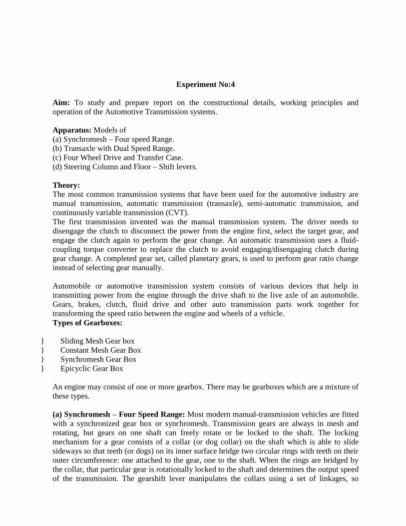
Experiment No:4
Aim: To study and prepare report on the constructional details, working principles and
operation of the Automotive Transmission systems.
Apparatus: Models of
(a) Synchromesh – Four speed Range.
(b) Transaxle with Dual Speed Range.
(c) Four Wheel Drive and Transfer Case.
(d) Steering Column and Floor – Shift levers.
Theory: The most common transmission systems that have been used for the automotive industry are
manual transmission, automatic transmission (transaxle), semi-automatic transmission, and
continuously variable transmission (CVT).
The first transmission invented was the manual transmission system. The driver needs to
disengage the clutch to disconnect the power from the engine first, select the target gear, and
engage the clutch again to perform the gear change. An automatic transmission uses a fluid-
coupling torque converter to replace the clutch to avoid engaging/disengaging clutch during
gear change. A completed gear set, called planetary gears, is used to perform gear ratio change
instead of selecting gear manually.
Automobile or automotive transmission system consists of various devices that help in
transmitting power from the engine through the drive shaft to the live axle of an automobile.
Gears, brakes, clutch, fluid drive and other auto transmission parts work together for
transforming the speed ratio between the engine and wheels of a vehicle.
Types of Gearboxes:
} Sliding Mesh Gear box
} Constant Mesh Gear Box
} Synchromesh Gear Box
} Epicyclic Gear Box
An engine may consist of one or more gearbox. There may be gearboxes which are a mixture of
these types.
(a) Synchromesh – Four Speed Range: Most modern manual-transmission vehicles are fitted
with a synchronized gear box or synchromesh. Transmission gears are always in mesh and
rotating, but gears on one shaft can freely rotate or be locked to the shaft. The locking
mechanism for a gear consists of a collar (or dog collar) on the shaft which is able to slide
sideways so that teeth (or dogs) on its inner surface bridge two circular rings with teeth on their
outer circumference: one attached to the gear, one to the shaft. When the rings are bridged by
the collar, that particular gear is rotationally locked to the shaft and determines the output speed
of the transmission. The gearshift lever manipulates the collars using a set of linkages, so

arranged so that one collar may be permitted to lock only one gear at any one time; when
"shifting gears", the locking collar from one gear is disengaged before that of another is
engaged. One collar often serves for two gears; sliding in one direction selects one transmission
speed, in the other direction selects another.
In a synchromesh gearbox, to correctly match the speed of the gear to that of the shaft as the
gear is engaged the collar initially applies a force to a cone-shaped brass clutch attached to the
gear, which brings the speeds to match prior to the collar locking into place. The collar is
prevented from bridging the locking rings when the speeds are mismatched by synchro rings.
The synchro ring rotates slightly due to the frictional torque from the cone clutch. In this
position, the dog clutch is prevented from engaging. The brass clutch ring gradually causes
parts to spin at the same speed. When they do spin the same speed, there is no more torque
from the cone clutch and the dog clutch is allowed to fall in to engagement. With continuing
sophistication of mechanical development, fully synchromesh transmissions with three speeds,
then four, and then five, became universal.
Fig: 4 speed gearbox
Construction, Working Principle and Operation of Synchromesh – Four Speed Range: If the teeth, the so-called dog teeth, make contact with the gear, but the two parts are spinning
at different speeds, the teeth will fail to engage and a loud grinding sound will be heard as they
clatter together. For this reason, a modern dog clutch in an automobile has a synchronizer
mechanism or synchromesh, which consists of a cone clutch and blocking ring. Before the teeth
can engage, the cone clutch engages first which brings the selector and gear to the same speed
using friction. Moreover, until synchronization occurs, the teeth are prevented from making
contact, because further motion of the selector is prevented by a blocker (or baulk) ring. When
synchronization occurs, friction on the blocker ring is relieved and it twists slightly, bringing
into alignment certain grooves and notches that allow further passage of the selector which
brings the teeth together.

Fig: Synchromesh Concept
(b) Transaxle with Dual Speed Range: I think it is beyond the scope of the students. The above statement involves electric speed
control system, hybrid transmission technology and race cars system.
(c) Four Wheel Drive and Transfer Case: A transfer case is a part of a four-wheel-drive
system found in four-wheel-drive. The transfer case is connected to the transmission and also to
the front and rear axles by means of drive shafts. It is also referred to as a "transfer gearcase",
"transfer gearbox", "transfer box" or "jockey box".
Construction, Working Principle and Operation of Four Wheel Drive and Transfer Case: A manually shifted 2-speed transfercase in the 4-wheel drive controls the power from the
engine and transmission to the front and rear driving axles (Fig). The transfer case shift lever
positions, from front to rear, are 4L (low gear, all wheels), N (Neutral), 2H (high gear, rear
wheels), and 4H (high gear, all wheels).
POWER FLOW - NEUTRAL POSITION: When the transfer case gears are in neutral (Fig),
power from the front main transmission drives the transfer case input shaft and drive gear. The
drive gear drives the idler shaft and the high-speed gear that free-runs on the front output shaft.
Therefore, no power can be delivered to either the front, or rear axle, even when the front main
transmission is in gear.
POWER FLOW—4L POSITION (LOW GEAR, ALL WHEELS): When the transfer case shift
lever is shifted into the 4-wheel low position, it pushes the two sliding gears back into
engagement with the idler shaft low-speed gear teeth. The power flows from the main drive
gear to the idler drive gear and shaft, and to the idler low-speed gear. From the low-speed, the
power flows through the two sliding gears to their respective output shafts to give speed
reduction.
POWER FLOW—2H POSITION (HIGH GEAR, REAR-WHEELS): When the transfer case
shift lever is shifted into the 2-wheel high position, the two sliding gears are pulled forward out
of engagement from the idler shaft low-speed gear, leaving the front output sliding gear in
neutral and pulling the rear output sliding gear farther forward into engagement with the clutch
teeth of the main drive gear. This locks the main input shaft directly to the rear wheel output

shaft. The power flows directly from the transmission to the rear axle without any reduction of
speed. The front output sliding gear remains in a neutral position, the idler shaft drive gear
turns the high-speed gear free on the front output shaft, and there is no power to the front axle.
POWER FLOW—4H POSITION (HIGH GEAR, ALL WHEELS): When the transfer case
shift lever is shifted into the 4-wheel high position, it pulls the rear output and front output
sliding gears forward into engagement with the clutch teeth of the main drive gears. This locks
the rear output shaft directly to the main input shaft, and the front output shaft to the high-speed
idler shaft gear. The power from the transmission flows from the drive gear in two directions.
Direct drive to the rear axle flows through the rear output shaft. Direct drive to the front axle
flows through the idler shaft drive gear, high-speed gear, and front output shaft.
(d) Steering Column and Floor – Shift levers: It comes under gear selection concept. In
manual transmissions, an interlock mechanism prevents the engagement of more than one gear
at any one time and a detent mechanism holds the gear, in detention, in the selected position. A
gearshift lever allows the driver to manually select gears via a gearshift mechanism.
Construction, Working Principle and Operation of Steering Column and Floor – Shift
levers: The lever can be mounted remote from the gearbox, on the floor or on the steering
column, and connected to the gearbox by a rod linkage or cables. It can also be mounted in the
top of the gearbox where it acts through a ball pivot in the top of the extension housing. In this
design, the lower end of the gear lever fits into a socket in a control shaft, inside the
transmission extension housing. A short lever on the other end of the shaft is located in a
selector gate, formed by slots in the three selector shift rails. They are supported in the casing
and are moved backwards or forwards by the lever. One rail moves to engage first or second
gear, another serves to engage third or fourth, and the other operates fifth or reverse. A selector
fork is attached to the first and second shift rail. It sits in a square section groove on the outside
of the first and second engagement sleeve. Similarly for the selection of third and fourth gears.
The reverse selector fork engages in a groove in the reverse engagement sleeve. Lateral
movement of the gear lever positions the control rod in line with the appropriate selector rail.
Longitudinal movement is transferred through the control rod and selector rail, to the fork, and

the engagement sleeve. Each rail has a detent mechanism, usually in the form of a spring
loaded steel ball, held in the casing. The ball engages in a groove in the rail when the gear lever
is in neutral and in a similar groove when a gear is selected. This holds the gear, in detention, in
the selected position. When a gear is changed or selected, an interlock mechanism prevents
more than one gear being engaged at the same time.
Fig: Steering Column Floor Shift Liver
Conclusion: Hence the study and preparation of report on the constructional details, working
principles and operation of the Automotive Transmission systems is completed.

EXPERIMENT 5 Aim: To study and prepare report on the constructional details, working principles and operation of the
Automotive Drive Lines & Differentials. Apparatus: Models of (a) Rear Wheel Drive Line. (b) Front Wheel Drive Line. (c) Differentials, Drive Axles and Four Wheel Drive Line. Theory: (a) Constructional details, Working Principles and Operation of Rear Wheel Drive Line: Rear-wheel drive (RWD) typically places the engine in the front of the vehicle and the driven wheels
are located at the rear, a configuration known as front-engine, rear-wheel drive line. The vast majority
of rear-wheel-drive vehicles use a longitudinally-mounted engine in the front of the vehicle, driving the
rear wheels via a driveshaft linked via a differential between the rear axles. Some FRL(front engine rear
wheel drive line) vehicles place the gearbox at the rear, though most attach it to the engine at the front.
Some of the advantages of FRL are even weight distribution, weight transfer during acceleration,
steering radius, better handling in dry conditions, better braking, towing, serviceability and robustness.
Fig: Rear Wheel Drive Line
(b) Constructional details, Working Principles and Operation of Front Wheel Drive Line. Front-wheel-drive lines are those in which the front wheels of the vehicle are driven. The most popular
lines used in cars today is the front-engine, front-wheel drive, with the engine in front of the front axle,
driving the front wheels. This line is typically chosen for its compact packaging; since the engine and
driven wheels are on the same side of the vehicle, there is no need for a central tunnel through the
passenger compartment to accommodate a prop-shaft between the engine and the driven wheels. As the
steered wheels are also the driven wheels, FFL (front-engine, front-wheel-drive line) cars are generally
considered superior to FRL (front-engine, rear-wheel-drive line) cars in conditions such as snow, mud
or wet tarmac. Some of the advantages are interior space, cost, improved drive train efficiency, placing
the mass of the drive train over the driven wheels moves the centre of gravity farther forward than a
comparable rear-wheel-drive layout, improving traction and directional stability on wet, snowy, or icy
surfaces.

Fig: Front Wheel Drive Line
(c) Constructional details, Working Principles and Operation of Differentials, Drive Axles and
Four Wheel Drive Line: In four wheel drive line vehicles, differentials are fitted to both front and rear axle assemblies. When a
two-wheel drive range is selected, the drive is transferred through the rear final drive and the differential
gears to the rear axle shafts and road wheels. The differential gears allow the rear wheels to rotate at
different speeds when the vehicle is turning, while continuing to transmit an equal turning effort to each
wheel. When four-wheel drive is engaged, the drive is transmitted through both front and rear axle
assemblies, and differential action occurs in both. However, in a turn, side-swiveling of the front wheels
for steering makes the front wheels travel a greater distance than the rear wheels. This causes a
difference in the rotational speeds of the front and rear wheels. Since there is also a difference between
inner and outer wheels, each axle shaft now turns at a different speed. Differences in speed can also
arise from differences in tread wear between front and rear, or in tire inflation pressures. Since front and
rear propeller shafts are locked together at the transfer case, the difference in speed cannot be absorbed
in the transmission, and the transmission drive line can be subjected to torsional stress.
Fig: 4 Wheel Drive Differential Axle Line
Conclusion: Hence the study and preparation of report on the constructional details, working principles
and operation of the Automotive Drive Lines & Differentials is completed.

Experiment No:6 Aim: To study and prepare report on the constructional details, working principles and operation of the
Automotive Suspension Systems. Apparatus: Models of (a) Front Suspension System. (b) Rear Suspension System. Theory: (a) Constructional details, working principles and operation of the Front Suspension System: The
shock absorber is contained inside the strut, and is a direct acting telescopic type shock absorber. The
coil spring is mounted over the strut, inside the suspension tower. The strut has an upper mounting point
in the suspension tower. For the front steerable suspension, the strut’s upper mounting is bushed, or
bearing-mounted, to allow for the steering movement. The control arm mount is fixed (or ‘held in
place’) in the vehicle configuration, by bushes. The lower control arm is attached to the vehicle body
and holds in place the strut, brake assembly, and drive shafts.
Fig: Front Suspension System
Another Example: This non-driven or 'dead' axle front suspension arrangement consists of: coil springs;
lower wishbone and upper wishbone as shown below.
Fig: Front Suspension System Layout

(b) Constructional details, working principles and operation of the Rear Suspension System: The
front of the leaf spring is attached to the chassis at the rigid spring hanger. This spring eye is bushed
with either rubber bushes or, in the case of heavy vehicles, steel bushes. The axle housing is rigid
between each road wheel. This means that any deflection to one side is transmitted to the other side. The
swinging shackle allows for suspension movement by allowing the spring to extend or reduce in length,
as the vehicle moves over uneven ground. The top of the shock absorber is attached to the chassis, and
to the spring pad at the bottom. It is a direct-acting shock absorber. The U-bolts attach the axle housing
to the leaf spring. They have a clamping force that helps to keep the leaf spring together. Leaf springs
are usually made of tempered steel. They hold the axle in position, both laterally and longitudinally. The
leaf spring is usually made up of a number of leaves of different length. The top, or longest leaf, is
normally referred to as the main leaf.
Fig: Rear Suspension System
Another example: This driven or 'live' rear axle arrangement consists of: shock absorbers; u-bolts; fixed
shackle; rebound clips and swinging shackles as shown below.
Fig: Rear Suspension System Layout
Conclusion: Hence the study and preparation of report on the constructional details, working principles
and operation of the Automotive Suspension Systems is completed.

Experiment No:7 Aim: To study and prepare report on the constructional details, working principles and operation of the
Automotive Steering Systems. Apparatus: Models of (a) Manual Steering Systems, e.g. Pitman –arm steering, Rack & Pinion steering. (b) Power steering Systems, e.g. Rack and Pinion Power Steering System. (c) Steering Wheels and Columns e.g. Tilt & Telescopic steering Wheels, Collapsible Steering
Columns. Theory: (a) Constructional details, working principles and operation of the Manual Steering Systems, e.g.
Pitman –arm steering, Rack & Pinion steering: The Pitman arm is a steering component in an automobile or truck. The pitman arm shaft is attached to
the steering box by a spline and nut. As the driver turns the steering wheel, the steering box mechanism
moves the steering linkages via the pitman arm shaft either left or right, depending on the direction in
which the steering wheel is turned. The steering box provides the change of angle at 90° to the steering
linkage. The idler arm is attached to the chassis and is positioned parallel to the pitman arm. The track
rod connects the pitman arm shaft to the idler arm shaft. In this way any movement in the pitman arm
shaft is directly applied to the idler arm shaft.
Fig: Pitman Arm Steering
The primary components of the rack and pinion steering system are: rubber bellows, pinion, rack,
inner ball joint or socket and tie-rod. This rubber bellows is attached to the Rack and Pinion housing. It
protects the inner joints from dirt and contaminants. In addition, it retains the grease lubricant inside the
rack and pinion housing. There is an identical bellows on the other end of the rack for the opposite side
connection. The pinion is connected to the steering column.
Fig: Rack & Pinion Steering

(b) Constructional details, working principles and operation of the Power steering Systems, e.g.
Rack and Pinion Power Steering System: The use of electronics into automotive steering systems enables much more sophisticated control to be
achieved. Electric steering is more economical to run, and easier to package and install than
conventional hydraulic power steering systems. Electrically Powered Hydraulic Steering, or EPHS,
replaces the customary drive belts and pulleys with a brushless motor that drives a high efficiency
hydraulic power steering pump in a conventional rack and pinion steering system. Pump speed is
regulated by an electric controller to vary pump pressure and flow. This provides steering efforts
tailored for different driving situations. The pump can be run at low speed or shut off to provide energy
savings during straight ahead driving. An EPHS system is able to deliver an 80 percent improvement in
fuel economy when compared to standard hydraulic steering systems. Electrically assisted steering or
EAS, is a power-assist system that eliminates the connection between the engine and steering system. There are four primary types of electric power assist steering systems: 1. Column-assist type. In this system the power assist unit, controller and torque sensor are attached to
the steering column. 2. Pinion-assist type. In this system the power assist unit is attached to the steering gear pinion shaft.
The unit sits outside the vehicle passenger compartment, allowing assist torque to be increased greatly
without raising interior compartment noise. 3. Rack-assist type. In this system the power assist unit is attached to the steering gear rack. It is located
on the rack to allow for greater flexibility in the layout design. 4. Direct-drive type. In this system the steering gear rack and power assist unit form a single unit. The
steering system is compact and fits easily into the engine compartment layout. The direct assistance to
the rack enables low friction and inertia, which in turn gives an ideal steering feel.
Fig: Power Steering
(c) Constructional details, working principles and operation of the Steering Wheels and Columns
e.g. Tilt & Telescopic steering Wheels, Collapsible Steering Columns: The original Tilt Wheel was developed by Edward James Lobdell in the early 1900s. Originally a luxury
option on cars, the tilt function helps to adjust the steering wheel by moving the wheel through an arc in
an up and down motion. Tilt Steering Wheels rely upon a ratchet joint located in the steering column
just below the steering wheel. By disengaging the ratchet lock, the wheel can be adjusted upward or
downward while the steering column remains stationary below the joint. Some designs place the pivot
slightly forward along the column, allowing for a fair amount of vertical movement of the steering
wheel with little actual tilt, while other designs place the pivot almost inside the steering wheel,
allowing adjustment of the angle of the steering wheel with almost no change it its height. Telescope
Wheel was developed by General Motors and can be adjusted to an infinite number of positions in a 3-

inch range. The Tilt and Telescope steering wheel was introduced as an exclusive option on Cadillac
automobiles.
Fig: Tilt & Telescope Column
Fig: Tilt & Telescope Wheel
Collapsible steering columns were invented long back but not successful in case of crash applications.
Fig: Collapsible Steering Column
Conclusion: Hence the study and preparation of report on the constructional details, working principles
and operation of the Automotive Steering Systems is completed.

Experiment No:8 Aim: To study and prepare report on the constructional details, working principles and operation of the
Automotive Tyres & wheels. Apparatus: Models of (a) Various Types of Bias & Radial Tyres. (b) Various Types of wheels. Theory: (a) Constructional details, working principles and operation of the Various Types of Bias &
Radial Tyres:
1. Bias: Bias tire (or cross ply) construction utilizes body ply cords that extend diagonally from
bead to bead, usually at angles in the range of 30 to 40 degrees, with successive plies laid at
opposing angles forming a crisscross pattern to which the tread is applied. The design allows the
entire tire body to flex easily, providing the main advantage of this construction, a smooth ride
on rough surfaces. This cushioning characteristic also causes the major disadvantages of a bias
tire: increased rolling resistance and less control and traction at higher speeds.
2. Belted bias: A belted bias tire starts with two or more bias-plies to which stabilizer belts are
bonded directly beneath the tread. This construction provides smoother ride that is similar to the
bias tire, while lessening rolling resistance because the belts increase tread stiffness. The plies
and belts are at different angles, which improve performance compared to non-belted bias tires.
The belts may be cord or steel. 3. Radial tyres: Radial tyre construction utilizes body ply cords extending from the beads and
across the tread so that the cords are laid at approximately right angles to the centerline of the
tread, and parallel to each other, as well as stabilizer belts directly beneath the tread. The belts
may be cord or steel. The advantages of this construction include longer tread life, better
steering control, and lower rolling resistance. Disadvantages of the radial tire include a harder
ride at low speeds on rough roads and in the context of off-roading, decreased "self-cleaning"
ability and lower grip ability at low speeds. 4. Solid: Many tires used in industrial and commercial applications are non-pneumatic, and are
manufactured from solid rubber and plastic compounds via molding operations. Solid tires
include those used for lawn mowers, skateboards, golf carts, scooters, and many types of light
industrial vehicles, carts, and trailers. One of the most common applications for solid tires is for
material handling equipment (forklifts). Such tires are installed by means of a hydraulic tire
press. 5. Semi-pneumatic: Semi-pneumatic tires have a hollow center, but they are not pressurized. They
are light-weight, low-cost, puncture proof, and provide cushioning. These tires often come as a
complete assembly with the wheel and even integral ball bearings. They are used on lawn
mowers, wheelchairs, and wheelbarrows. They can also be rugged, typically used in industrial
applications, and are designed to not pull off their rim under use.

Fig: Bias Tyre
Fig: Radial Tyre
(b) Constructional details, working principles and operation of the Various Types of wheels: Wheels must be strong enough to carry the mass of the vehicle, and withstand the forces that are
generated during use. Some are made from steel. They are pressed in 2 sections - the wheel center, with
a flange or disc that is drilled for the wheel fasteners, and the rim. They are then welded together. Others
are made from cast aluminum alloy. Alloy wheels are lighter than similar steel wheels, and since
aluminum is a better heat conductor than steel, alloy wheels dissipate heat from brakes and tires more
quickly than steel wheels. The wheel center must accurately locate the wheel rim centrally on the axle.
It must also provide the required distance from the centerline of the wheel, to the face of the mounting
flange. This is called offset. Offset is important because it brings the tire centerline into close alignment
with the larger inner hub bearing, and reduces load on the stub axle. This allows the inside of the wheel
center to be shaped to provide space for the brake assembly, usually located inside the wheel.
Ventilation slots allow air to circulate around the brakes. In some cases wheels are directional to assist

the airflow. The rim must be accurately shaped, and dimensioned, and strong enough to support the tire
under the load of the vehicle and the forces generated by the motion of the vehicle. Passenger cars
normally use rims which are of well based, or drop-center design. The drop-center is used for mounting
and demounting the tire onto the rim. When inflated, the tire is locked to the rim by tapering the bead
seat towards the flange, or by safety ridges or humps, close to the flange. In the event of sudden
deflation, or blowout, safety ridges prevent the tire moving down into the well. This helps maintain
control of the vehicle while it is being braked. Well-based rims can also be used on heavy commercial
vehicles for tubeless tires. The rims are referred to as 15-degree drop-center rims, because the bead seats
are inclined at 15 degrees towards the flange. The taper gives a good grip, and an airtight seal between
the tire beads, and the rim. The low flanges and drop-center allow the special size, flexible, tubeless
truck tires to be mounted and demounted in a similar manner to that used on smaller passenger car tires.
The stiff sidewalls of larger cross-ply tires mean they cannot be mounted and demounted in this way,
and many 4-wheel-drive and commercial vehicles use a flat-base, demountable flange rim. When all of
the air is removed from the tire, one flange can be removed so the tire can be demounted. Wheels are
fastened to the hubs by wheel studs and nuts. They are highly stressed by loads from the weight of the vehicles, and the forces generated by its
motion, and they’re made from heat-treated, high-grade alloy-steel. The threads between the studs and
nuts are close fitting and accurately-sized. All wheel nuts must be tightened to the correct torque,
otherwise the wheel could break free from the hub. Conclusion: Hence the study and preparation of report on the constructional details, working principles
and operation of the Automotive Tyres & wheels is completed.

Experiment No:9 Aim: To study and prepare report on the constructional details, working principles and operation of the
Automotive Brake systems. Apparatus: Models of (a) Hydraulic & Pneumatic Brake systems. (b) Drum Brake System. (c) Disk Brake System. (d) Antilock Brake System. (e) System Packing & Other Brakes. Theory: (a) Constructional details, working principles and operation of the Hydraulic & Pneumatic Brake
systems: The Hydraulic brake system is a braking system which uses brake fluid usually includes ethylene
glycol, to transmit pressure from the controlling unit, which is usually near the driver, to the actual
brake mechanism, which is near the wheel of the vehicle. The most common arrangement of hydraulic
brakes for passenger vehicles, motorcycles, scooters, and mopeds, consists of the following: Brake pedal or Brake lever Pushrod, also called an actuating rod Reinforced hydraulic lines Rotor or a brake disc or a drum attached to a wheel Master cylinder assembly includes: Piston assembly is made up of one or two pistons, a return spring, a
series of gaskets or O-rings and fluid reservoir.
Fig: Hydraylic-Brake

In Hydraulic brake system when the brake pedal or brake lever is pressed, a pushrod applies force on the
piston in the master cylinder causing fluid from the brake fluid tank to run into a pressure chamber
through a balancing port which results in increase in the pressure of whole hydraulic system. This forces
fluid through the hydraulic lines to one or more calipers where it works upon one or two extra caliper
pistons protected by one or more seated O-rings which prevent the escape of any fluid from around the
piston. The brake caliper piston then apply force to the brake pads. This causes them to be pushed
against the rotating rotor, and the friction between pads and rotor causes a braking torque to be
generated, slowing the vehicle. Heat created from this friction is dispersed through vents and channels
in rotor and through the pads themselves which are made of particular heat-tolerant materials like
kevlar, sintered glass. The consequent discharge of the brake pedal or brake lever lets the spring(s)
within the master cylinder assembly to return that assembly piston(s) back into position. This reduces
the hydraulic pressure on the caliper lets the brake piston in the caliper assembly to slide back into its
lodging and the brake pads to discharge the rotor. If there is any leak in the system, at no point does any
of the brake fluid enter or leave. Pneumatic or Air Brake System is the brake system used in automobiles such as buses, trailers, trucks,
and semi-trailers. The Compressed Air Brake System is a different air brake used in trucks which
contains a standard disc or drum brake using compressed air instead of hydraulic fluid. The compressed
air brake system works by drawing clean air from the environment, compressing it, and hold it in high
pressure tanks at around 120 PSI. Whenever the air is needed for braking, this air is directed to the
functioning cylinders on brakes to activate the braking hardware and slow the vehicle. Air brakes use
compressed air to increase braking forces.
Fig: Air Break
(b) Constructional details, working principles and operation of the Drum Brake System: Drum brakes consist of a backing plate, brake shoes, brake drum, wheel cylinder, return springs and an
automatic or self-adjusting system. Brake Shoes: Like the disk pads, brake shoes consist of a steel shoe with the friction material or lining
riveted or bonded to it. Backing Plate: The backing plate is what holds everything together. It attaches to the axle and forms a
solid surface for the wheel cylinder, brake shoes and assorted hardware.

Brake Drum: Brake drums are made of iron and have a machined surface on the inside where the shoes
make contact. Just as with disk rotors, brake drums will show signs of wear as the brake linings seat
themselves against the machined surface of the drum. Wheel Cylinder: The wheel cylinder consists of a cylinder that has two pistons, one on each side. Each
piston has a rubber seal and a shaft that connects the piston with a brake shoe. When brake pressure is
applied, the pistons are forced out pushing the shoes into contact with the drum. Wheel cylinders must
be rebuilt or replaced if they show signs of leaking. Return Springs: Return springs pull the brake shoes back to their rest position after the pressure is
released from the wheel cylinder. If the springs are weak and do not return the shoes all the way, it will
cause premature lining wear because the linings will remain in contact with the drum. Self Adjusting System: The parts of a self adjusting system should be clean and move freely to insure
that the brakes maintain their adjustment over the life of the linings. If the self adjusters stop working,
you will notice that you will have to step down further and further on the brake pedal before you feel the
brakes begin to engage. Disk brakes are self adjusting by nature and do not require any type of
mechanism.
(c) Constructional details, working principles and operation of the Disk Brake System: The disk brake is the best brake we have found so far. Disk brakes are used to stop everything from cars
to locomotives and jumbo jets. Disk brakes wear longer, are less affected by water, are self adjusting,
self cleaning, less prone to grabbing or pulling and stop better than any other system around. The main
components of a disk brake are the Brake Pads, Rotor, Caliper and Caliper Support. Brake Pads: There are two brake pads on each caliper. They are constructed of a metal "shoe" with the
lining riveted or bonded to it. The pads are mounted in the caliper, one on each side of the rotor. Brake
linings used to be made primarily of asbestos because of its heat absorbing properties and quiet
operation; however, due to health risks, asbestos has been outlawed, so new materials are now being
used. Rotor: The disk rotor is made of iron with highly machined surfaces where the brake pads contact it.
Just as the brake pads wear out over time, the rotor also undergoes some wear, usually in the form of
ridges and groves where the brake pad rubs against it. Caliper & Support: There are two main types of calipers: Floating calipers and fixed calipers. A floating
caliper "floats" or moves in a track in its support so that it can center itself over the rotor. As you apply
brake pressure, the hydraulic fluid pushes in two directions. It forces the piston against the inner pad,
which in turn pushes against the rotor. It also pushes the caliper in the opposite direction against the

outer pad, pressing it against the other side of the rotor. Four Piston Fixed Calipers are mounted rigidly
to the support and are not allowed to move. Instead, there are two pistons on each side that press the
pads against the rotor.
(d) Constructional details, working principles and operation of the Antilock Brake System: An anti-lock braking system abbreviated as ABS is a braking system or security system which
prevents the wheels on an automobile from locking up while braking. The wheels revolving on the road
let the driver to maintain steering control under heavy braking by preventing a skid and allowing the
wheel to continue interacting tractively with the road surface as directed by driver steering inputs. The
ABS offers better vehicle control, and may reduce ending distances on dry and especially slippery
surfaces. It can also boost braking distance on loose surfaces such as snow and gravel.
Fig: Antilock-Braking-System-(ABS)

(e) Constructional details, working principles and operation of the System Packing & Other
Brakes: Parking Brakes: The parking brake (a.k.a. emergency brake) system controls the rear brakes through a
series of steel cables that are connected to either a hand lever or a foot pedal. The idea is that the system
is fully mechanical and completely bypasses the hydraulic system so that the vehicle can be brought to a
stop even if there is a total brake failure. On drum brakes, the cable pulls on a lever mounted in the rear
brake and is directly connected to the brake shoes. This has the effect of bypassing the wheel cylinder
and controlling the brakes directly. Disk brakes on the rear wheels add additional complication for
parking brake systems. There are two main designs for adding a mechanical parking brake to rear disk
brakes. The first type uses the existing rear wheel caliper and adds a lever attached to a mechanical
corkscrew device inside the caliper piston. When the parking brake cable pulls on the lever, this
corkscrew device pushes the piston against the pads, thereby bypassing the hydraulic system, to stop the
vehicle. This type of system is primarily used with single piston floating calipers, if the caliper is of the
four piston fixed type, then that type of system can't be used. The other system uses a complete
mechanical drum brake unit mounted inside the rear rotor. The brake shoes on this system are connected
to a lever that is pulled by the parking brake cable to activate the brakes. The brake "drum" is actually
the inside part of the rear brake rotor. I think system packing is not the relevant word w.r.t brake system, so it is beyond the scope. Conclusion: Hence the study and preparation of report on the constructional details, working principles
and operation of the Automotive Brake systems is completed.

Experiment No:10 Aim: To study and prepare report on the constructional details, working principles and operation of
Automotive Emission / Pollution control systems. Apparatus: Model of Automotive Emission / Pollution control systems. Theory: The need to control the emissions from automobiles gave rise to the computerization of the
automobile. Hydrocarbons, carbon monoxide and oxides of nitrogen and particulates are created during
the combustion process and are emitted into the atmosphere from the tail pipe. There are also
hydrocarbons emitted as a result of vaporization of gasoline and from the crankcase of the automobile.
Some of the more popular emission control systems installed on the automobile are: EGR valve,
catalytic converter, EVAP system, air injection system, PCV valve, charcoal canister. Sources of vehicle emissions are Engine Crankcase Blow-by Fumes (20%)– heating oil and burning of
fuel that blows past piston rings and into the crankcase. Fuel Vapour (20%) – chemicals that enter the
air as fuel evaporates. Engine Exhaust (60%)- blown out the tailpipe when engine burns a hydrocarbon
based fuel. Constructional details, working principles and operation of Automotive Emission / Pollution
control systems: PCV Valve: The purpose of the positive crankcase ventilation (PCV) system is to take the vapors
produced in the crankcase during the normal combustion process, and redirecting them into the air/fuel
intake system to be burned during combustion. These vapors dilute the air/fuel mixture so they have to
be carefully controlled and metered in order to not affect the performance of the engine. This is the job
of the positive crankcase ventilation (PCV) valve. At idle, when the air/fuel mixture is very critical, just
a little of the vapors are allowed in to the intake system. At high speed when the mixture is less critical
and the pressures in the engine are greater, more of the vapors are allowed in to the intake system. When
the valve or the system is clogged, vapors will back up into the air filter housing or at worst; the excess
pressure will push past seals and create engine oil leaks. If the wrong valve is used or the system has air
leaks, the engine will idle rough, or at worst, engine oil will be sucked out of the engine.
Fig: PCV System

Evaporative Emission Control Systems (EVAP): It prevents toxic fuel system vapours from entering
the atmosphere. It consists of parts non-vented fuel tank cap which prevents fuel vapours from entering
the atmosphere, air dome is hump formed at the top of the tank for fuel expansion, charcoal canister
which stores vapours when the engine is not running, purge line/valve which controls the flow of
vapours from the canister to the intake manifold that allows flow when engine reaches operating
temperature and is operating above idle speed.
Fig: EVAP System
Exhaust Gas Recirculation (EGR): The purpose of the exhaust gas recirculation valve (EGR) valve is
to meter a small amount of exhaust gas into the intake system, this dilutes the air/fuel mixture so as to
lower the combustion chamber temperature. Excessive combustion chamber temperature creates oxides
of nitrogen, which is a major pollutant. While the EGR valve is the most effective method of controlling
oxides of nitrogen, in it's very design it adversely affects engine performance. The engine was not
designed to run on exhaust gas. For this reason the amount of exhaust entering the intake system has to
be carefully monitored and controlled. This is accomplished through a series of electrical and vacuum
switches and the vehicle computer.
Fig: EGR System

Air Injection System: Since no internal combustion engine is 100% efficient, there will always be
some unburned fuel in the exhaust. This increases hydrocarbon emissions. To eliminate this source of
emissions an air injection system was created. Combustion requires fuel, oxygen and heat. Without any
one of the three, combustion cannot occur. Inside the exhaust manifold there is sufficient heat to support
combustion, if we introduce some oxygen than any unburned fuel will ignite. This combustion will not
produce any power, but it will reduce excessive hydrocarbon emissions. Unlike in the combustion
chamber, this combustion is uncontrolled, so if the fuel content of the exhaust is excessive, explosions,
that sound like popping, will occur.
Fig: Air Injection System
Catalytic Converter System: Automotive emissions are controlled in three ways, one is to promote
more complete combustion so that there are less by products. The second is to reintroduce excessive
hydrocarbons back into the engine for combustion and the third is to provide an additional area for
oxidation or combustion to occur. This additional area is called a catalytic converter. The catalytic
converter looks like a muffler. It is located in the exhaust system ahead of the muffler. Inside the
converter are pellets or a honeycomb made of platinum or palladium. The platinum or palladium are
used as a catalyst (a catalyst is a substance used to speed up a chemical process).
Fig: Catalytic Converter System
Conclusion: Hence the study and preparation of report on the constructional details, working principles
and operation of Automotive Emission / Pollution control systems is completed.