
Automation Technology and Interface Electronic · 3 gy dition 2017/2018 gy ull Line Catalog...
64
1 Rail-Mount Terminal Block Systems Full Line Catalog, Volume 1 – Edition 2017/2018 PCB Terminal Blocks and Connectors Full Line Catalog, Volume 2 – Edition 2017/2018 2 3 Automation Technology Full Line Catalog, Volume 3 – Edition 2017/2018 4 Interface Electronic Full Line Catalog, Volume 4 – Edition 2017/2018 5 WINSTA ® – The Pluggable Connection System Full Line Catalog, Volume 5 – Edition 2017/2018 6 Marking Full Line Catalog, Volume 6 – Edition 2017/2018 Automation Technology and Interface Electronic 6XSSOHPHQWDU\ &DWDORJ WR )XOO /LQH &DWDORJV 9ROXPHV Edition 2017/1
-
Upload
hoangthuan -
Category
Documents
-
view
214 -
download
0
Transcript of Automation Technology and Interface Electronic · 3 gy dition 2017/2018 gy ull Line Catalog...

1Rail-Mount Terminal Block SystemsFull Line Catalog, Volume 1 – Edition 2017/2018
PCB Terminal Blocks and ConnectorsFull Line Catalog, Volume 2 – Edition 2017/2018 2 3Automation Technology
Full Line Catalog, Volume 3 – Edition 2017/2018
4Interface ElectronicFull Line Catalog, Volume 4 – Edition 2017/2018 5WINSTA® – The Pluggable Connection System
Full Line Catalog, Volume 5 – Edition 2017/2018 6MarkingFull Line Catalog, Volume 6 – Edition 2017/2018
Automation Technology and Interface Electronic
Edition 2017/1
3
Automation Technology
Full Line Catalog, Volume 3 – Edition 2017/2018
Auto
mat
ion
Tech
nolo
gy
Full L
ine
Cata
log
2017
/201
8
4
Interface Electronic
Full Line Catalog, Volume 4 – Edition 2017/2018
Inte
rfac
e El
ectr
onic
Full L
ine
Cata
log
2017
/201
86
Marking
Full Line Catalog, Volume 6 – Edition 2017/2018
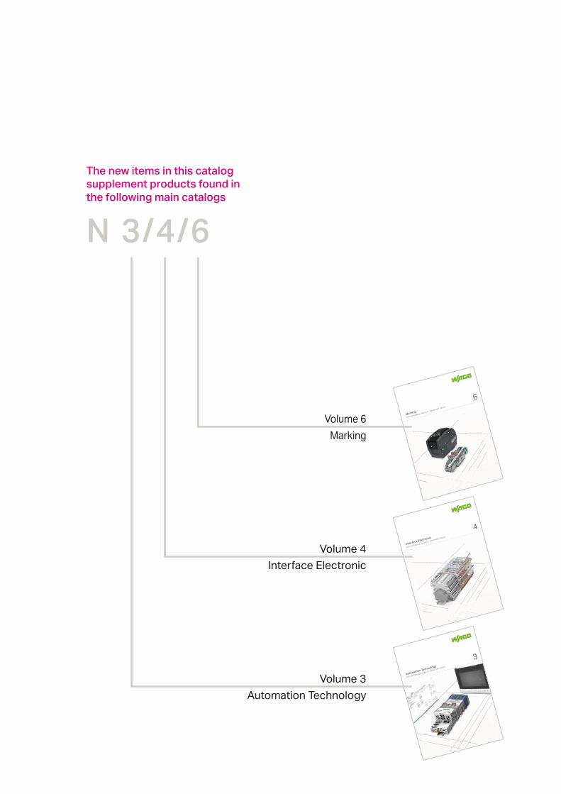
N 3/4/6
The new items in this catalog supplement products found in the following main catalogs
Volume 3Automation Technology
Volume 4Interface Electronic
Marking

www.wago.com
1Supplementary Catalog AUTOMATION 1/2017
AUTOMATION
Marking
INTERFACE ELECTRONIC
Page
Supplementary Catalog AUTOMATION 1/2017
4
26
54
Indexes and Addresses 57

www.wago.com
2 Supplementary Catalog AUTOMATION 1/2017
Contents
Page
Description Item No.Application Controllers for Lighting Management and Energy Data Management
Lighting Management Software and Components 4Controller PFC200 750-8202/000-012 5
Energy Data Management Software and Components 6Controller PFC200 750-8202/000-022 7
750 and 753 I/O-SystemsCC-Link Fieldbus Coupler; 156 kBaud ... 10 Mbaud 750-325 8Power Measurement; 277 VAC/DC; External Shunts 750-494/000-005 10M-Bus Master 753-649 12SMI Master SMI Master; 230 VAC 753-1630 13
SMI Master LoVo; 24 VDC 753-1631 13750 XTR I/O-System, Intrinsically Safe
General Product Information 14Standards and Rated Conditions 15Supply Module; 24 VDC; Extreme, for Intrinsically Safe XTR Modules
750-606/040-000 16
8-Channel Digital Input; NAMUR; Intrinsically Safe; Extreme 750-439/040-000 172-Channel Digital Output; 24 VDC; Intrinsically Safe; Extreme 750-535/040-000 184-Channel Analog Input; 0/4 … 20 mA; Intrinsically Safe; Extreme 750-486/040-000 192-Channel Analog Input; 4 … 20 mA HART; Intrinsically Safe; Extreme
750-484/040-000 20
2-Channel Analog Input; Resistance Measurement; Intrinsically Safe; Extreme
750-481/040-000 21
2-Channel Analog Output; 0 … 20 mA; Intrinsically Safe; Extreme 750-585/040-000 22Up/Down Counter; Intrinsically Safe; Extreme 750-633/040-000 23
Industrial SwitchesIndustrial Switches, 16-port 1000Base-T 852-1106 24
Volume 3, Automation Technology

www.wago.com
3Supplementary Catalog AUTOMATION 1/2017
Contents
Page
Description Item No.
JUMPFLEX® Signal Conditioners
857-424 26
Voltage Signal Conditioner 857-560 28
Power Signal Conditioner 857-569 30
Loop-Powered RTD Temperature Signal Conditioner 857-815 32
Plug-In Current Transformers
Technical Data 34
Primary Rated Current 250 A, Rated Power 5 VA 855-401/250-501 35
Primary Rated Current 400 A, Rated Power 10 VA 855-501/400-1001 35
Primary Rated Current 600 A, Rated Power 10 VA 855-501/600-1001 35
Primary Rated Current 800 A, Rated Power 10 VA 855-501/800-1001 35
Primary Rated Current 1000 A, Rated Power 10 VA 855-801/1000-1001 35
Current and Voltage Tap for 95 mm² High-Current Through Terminal Block (285-195)
855-951/250-000 36
EPSITRON® ECO Power, Switched-Mode Power Supply
Technical Data 38
Output 24 VDC / 20 A 787-2742 39
Output 24 VDC / 40 A 787-2744 39
EPSITRON® Electronic Circuit Breakers (ECBs)
Technical Data 40
Nominal Current 1 A 787-2861/100-000 41
Nominal Current 2 A 787-2861/200-000 41
Nominal Current 4 A 787-2861/400-000 42
Nominal Current 6 A 787-2861/600-000 42
Nominal Current 8 A 787-2861/800-000 43
Nominal Current 1 … 8 A 787-2861/108-020 43
EPSITRON® Power Supply for Fan Control
787-914 44
EPSITRON® Radio Interference Suppression Filter
787-980 45
Potential Distribution Modules
Technical Data 46
830-800/… 47 … 53
Marking
Micro-WSB Inline Markers 2009-141 54
Circuit ID Labels 210-813 55
Volume 4, Interface Electronic
Products highlighted in RED are new items for Spring 2017

4
www.wago.com
Supplementary Catalog AUTOMATION 1/2017
Volume 3, Section 1 | Software
WAGO Lighting Management
WAGO Lighting Management is a proven concept based on predefined hard-ware and preconfigured software, which greatly simplifies planning, commis-sioning and operation.The basic idea: WAGO Lighting Management is based on different lighting re-quirements in warehouses and production facilities.For example, a production facility is divided into virtual rooms in which the light can be flexibly adapted. Each virtual room receives signals from the sensors and actuators in order to automatically set the appropriate light intensity. By using the virtual rooms, conversions and room remodeling can be implemented quick-ly and simply via Web configuration.
WAGO Lighting ManagementComponents Item No. Note
Base unit Lighting Management – Controller 750-8202/000-012 The controllers can communicate with each other.
Lighting Management – Software Free of charge Download: wago.com/applicationcontrollerDALI Multi-Master 753-647 In addition to 64 DALI actuators (ECGs), a DALI-Multi Master supports up to 16 DALI-
End Module 750-600
Power Supply to I/O Node 787-1012 24 VDC supply voltage for controllers and additional modules
Power Supply for DALI Multi-Master 787-1007 Power supply for max. 5 DALI Multi Masters
Extension for inputs/push-buttons
16-Channel Digital Input; 24 VDC; 3 ms 750-1405 For 1 … 16 light push-buttons/switch inputs; max. 4 extensions per base package
Extension for outputs/ Actuators
16-Channel Digital Output; 24 VDC; 0.5 A 750-1504 For 1 … 16 actuators/lamps/relays/ECG control; max. 2 extensions per base package
Socket with ALZ Relay; 1 changeover contact each (1 u); 24 VDC
788-354 Light switching via relay
Extension for EnOcean radio
RS-232/-485 Serial Interface 750-652 Serial interface for connecting the EnOcean radio transmitter/receiver STC65-RS485-EVC for 1 … 64 switch jacks
EnOcean Receiver/Transmitter 2852-7101 EnOcean radio signal recording and transmission to the I/O node
EnOcean Repeater 2852-7102 Transmission range extension, further information on planning on the EnOcean website
250; 2-channel lighting control758-940/001-000 1 … 2 or 1 … 4 signals, range of 30 meters in buildings to the radio receiver
250; 4-channel lighting control758-940/003-000
Extension for external time request
Real-Time Clock module 750-640 Time synchronization module, if no time server connection is possible
GPS DCF Converter 2852-7901 Converter/external receiver for time synchronization
Extension for energy data measurement
3-Phase Power Measurement; 690 VAC 1 A
750-495/xxx-xxx
Connections for current and voltage 2007-8874, 2007-8877 Pre-assembled terminal block assemblies for easy connection and short-circuiting of current transformers (current transformers, see Full Line Catalog Volume 4)
Extension for sensors
DALI Multi-Sensor Kit 2851-8201 Brightness measurement and motion sensor: Set for connection to a DALI bus system
DALI Sensor Coupler 2851-8202 Sensor coupler for connecting MULTI-3-CI sensors to DALI Max. 16 DALI sensor couplers per DALI Multi Master (753-647)
DALI HIGHBAY ADAPTER + HIGH BAY 2852-7207, 2852-7201 Brightness measurement and motion sensor for large installation heights (3 … 13 meters)
DALI HIGHBAY ADAPTER + VISION 2852-7207, 2852-7202 Motion sensor for large areas, large rooms, corridors or storage rooms
DALI LS/PD LI 2852-7203
DALI Sensor Coupler HF LS LI + Radar Sensor HF LS LI
2852-7205, 2852-7206 Light and recessed ceiling sensor: combined daylight and motion detection, motion detection via radar
DALI XC 2852-7301 Push-button coupler for connecting 4 conventional push-buttons to DALI
DALI Sensor Coupler E 2852-7204 Sensor coupler for connecting standard sensors to DALI

5
www.wago.com
U6U5U4U3
RUNSTOPRESET
U2U1
SYS RSTRUNI/OMSNSU7
750-
8202
SD
24V 0V
+ +
— —
01 02A
B
ACT
ACT
LNK
ETHLN
KX3
RS23
2/48
5X1
X2
Serial interface
Fieldbus connection
2 x RJ-45 (switched)
SD memory card
slot
Supplementary Catalog AUTOMATION 1/2017
Volume 3, Section 3.1 | PFC100/PFC200 Controllers
Controller PFC200
Item Description PFC200Version FG2 2ETH RSItem No. 750-8202/000-012
Technical DataFieldbus Modbus TCPProtocols DHCP, DNS, NTP, FTP, FTPS, SNMP, HTTP, HTTPS, SSH, MODBUS (TCP, UDP, RTU)Communication RS-232/-485 serial interface (switchable)Visualization Web-Visu, WebserverProgramming WAGO-I/O-PRO V2.3 (based on CODESYS 2.3), e!COCKPIT (based on CODESYS 3)CPUOperating system Real-time Linux (with RT-Preempt patch)
non-volatile memory (hardware)Program memory/data memory/non-volatile memory (software)
CODESYS 2: e!RUNTIME:
Number of I/O modules per node (max.) 250Input and output process image (internal) max. 1000 wordsInput and output process image (MODBUS) max. CODESYS 2: 1000 words
e!RUNTIME: 32,000 words
Supply voltage (system)Total current for system supply 1700 mAAmbient temperature (operation) 0 … +55 °CDimensions W x H x D
Approvals 1, r UL 508, ANSI/ISA, 4 ATEX/IECExData sheet and further information, see: wago.com/750-8202/000-012
Accessories Item No.758-879/000-001
WAGO communication cable 750-923
Figure: 750-8202
FG2; 2 x ETHERNET; RS-232/-485
e!COCKPIT, WAGO-I/O-PRO Software V2.3 see Full Line Catalog, Volume 3
Mini-WSB Quick Marking System, see Full Line Catalog, Volume 6

6
www.wago.com
Supplementary Catalog AUTOMATION 1/2017
Volume 3, Section 1 | Software
WAGO Energy Data ManagementComponents Item No. Number of Modules
(max.)Base unit Energy Data Management – Controller 750-8202/000-022 1
Energy Data Management – Software Download: wago.com/applicationcontroller
1
End Module 750-600 1Power Supply to I/O Node, 230 VAC/24 VDC; 2.5 A 787-1012 1Power Supply to I/O Node, 230 VAC/24 VDC; 2 A 787-1606 1
Recording real power pulse EVU 4-Channel Digital Input; 24 VDC; 3 ms 750-402 1Recording S0 and pulse counter 750-638 43-Phase Power Measurement 3-Phase Power Measurement; 690 VAC 1 A 750-495 total: 18
3-Phase Power Measurement; 690 VAC 5 A 750-495/000-001
750-495/000-002
other analog signals750-452 1
8-Channel Analog Input; 0/4 … 20 mA; Single-Ended 750-496 28-Channel Analog Input; 0 … 10 VDC/±10 V, Single-Ended 750-497 2
Resistance sensors 8-Channel Analog Input; Resistance Measurement; Adjustable 750-451 2Extension for connecting the M-Bus level converter
RS-232/485 Serial Interface 750-652 1M-Bus Level Converter upon request 1
Extension for connecting the EnOcean gateway
RS-232/485 Serial Interface 750-652 1EnOcean Receiver/Transmitter with RS-485 EVC Interface 2852-7101 1
WAGO Energy Data Management
The WAGO Energy Data Management system easily records, visualizes and manages energy data without any programming and can be upgraded at any time.The energy data management system provides energy flow monitoring via user-friendly Web visualization. The connected I/O modules (see table) are automatically detected and can be configured via user interface. In addition to energy-specific values like electrical currents or voltages, the WAGO Controller can record other measurement variables relevant for industrial and process
compressed air and temperature.
With the integrated visualization tool, collected data are readily displayed and evaluated in various forms.The data are transferred to higher level energy management software via Mod-bus TCP/IP or as a CSV file via FTPS. In addition, it is possible to store the history on the SD card integrated in the controller. Because it is so easy to integrate the versatile new WAGO solution into existing systems, increasing measurement point depth is also a simple matter.

7
www.wago.com
U6U5U4U3
RUNSTOPRESET
U2U1
SYS RSTRUNI/OMSNSU7
750-
8202
SD
24V 0V
+ +
— —
01 02A
B
ACT
ACT
LNK
ETHLN
KX3
RS23
2/48
5X1
X2
Serial interface
Fieldbus connection
2 x RJ-45 (switched)
SD memory card
slot
Supplementary Catalog AUTOMATION 1/2017
Volume 3, Section 3.1 | PFC100/PFC200 Controllers
Controller PFC200Energy Data Management Application; 2 x ETHERNET, RS-232/-485
Item Description PFC200Version FGE 2ETH RSItem No. 750-8202/000-022
Technical DataFieldbus Modbus TCPProtocols DHCP, DNS, NTP, FTP, FTPS, SNMP, HTTP, HTTPS, SSH, MODBUS (TCP, UDP, RTU)Communication RS-232/-485 serial interface (switchable)Visualization Web-Visu, WebserverProgramming WAGO-I/O-PRO V2.3 (based on CODESYS 2.3), e!COCKPIT (based on CODESYS 3)CPUOperating system Real-time Linux (with RT-Preempt patch)
non-volatile memory (hardware)Program memory/data memory/non-volatile memory (software)
CODESYS 2: e!RUNTIME:
Number of I/O modules per node (max.) 250Input and output process image (internal) max. 1000 wordsInput and output process image (MODBUS) max. CODESYS 2: 1000 words
e!RUNTIME: 32,000 words
Supply voltage (system)Total current for system supply 1700 mAAmbient temperature (operation) 0 … +55 °CDimensions W x H x D
Approvals 1, r UL 508, ANSI/ISA, 4 ATEX/IECExData sheet and further information, see: wago.com/750-8202/000-022
Accessories Item No.758-879/000-001
WAGO communication cable 750-923
Figure: 750-8202
e!COCKPIT, WAGO-I/O-PRO Software V2.3 see Full Line Catalog, Volume 3
Mini-WSB Quick Marking System, see Full Line Catalog, Volume 6
www.wago.com
8
x1
x10
I/O
RD
SD
L RUN
L ERR
750-
325
12
34
56
78
ON
24V 0V
+ +
— —
01 02
012345678
9
012345678
9
A
B
Fieldbus
connection
231 Series (MCS)
Operation mode, cyclic
setting, occupied stations,
baud rate
Adress
Supplementary Catalog AUTOMATION 1/2017
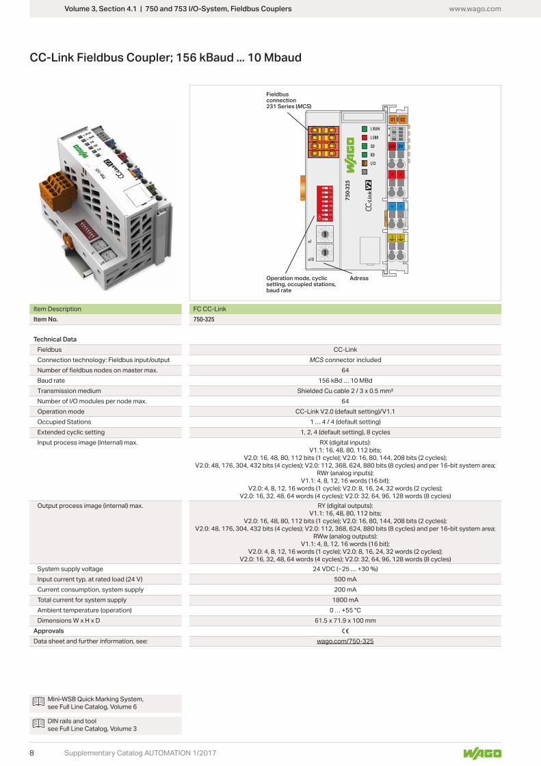
Volume 3, Section 4.1 | 750 and 753 I/O-System, Fieldbus Couplers
CC-Link Fieldbus Coupler; 156 kBaud ... 10 Mbaud
Item Description FC CC-LinkItem No. 750-325
Technical DataFieldbus CC-LinkConnection technology: Fieldbus input/output MCS connector included
64Baud rate 156 kBd … 10 MBdTransmission medium Shielded Cu cable 2 / 3 x 0.5 mm²Number of I/O modules per node max. 64Operation mode CC-Link V2.0 (default setting)/V1.1Occupied Stations 1 … 4 / 4 (default setting)Extended cyclic setting 1, 2, 4 (default setting), 8 cyclesInput process image (internal) max. RX (digital inputs):
V1.1: 16, 48, 80, 112 bits; V2.0: 16, 48, 80, 112 bits (1 cycle); V2.0: 16, 80, 144, 208 bits (2 cycles);
V2.0: 48, 176, 304, 432 bits (4 cycles); V2.0: 112, 368, 624, 880 bits (8 cycles) and per 16-bit system area; RWr (analog inputs):
V1.1: 4, 8, 12, 16 words (16 bit); V2.0: 4, 8, 12, 16 words (1 cycle); V2.0: 8, 16, 24, 32 words (2 cycles);
V2.0: 16, 32, 48, 64 words (4 cycles); V2.0: 32, 64, 96, 128 words (8 cycles)Output process image (internal) max. RY (digital outputs):
V1.1: 16, 48, 80, 112 bits; V2.0: 16, 48, 80, 112 bits (1 cycle); V2.0: 16, 80, 144, 208 bits (2 cycles);
V2.0: 48, 176, 304, 432 bits (4 cycles); V2.0: 112, 368, 624, 880 bits (8 cycles) and per 16-bit system area; RWw (analog outputs):
V1.1: 4, 8, 12, 16 words (16 bit); V2.0: 4, 8, 12, 16 words (1 cycle); V2.0: 8, 16, 24, 32 words (2 cycles);
V2.0: 16, 32, 48, 64 words (4 cycles); V2.0: 32, 64, 96, 128 words (8 cycles)System supply voltage
500 mACurrent consumption, system supply 200 mATotal current for system supply 1800 mAAmbient temperature (operation) 0 … +55 °CDimensions W x H x D 61.5 x 71.9 x 100 mm
Approvals 1
Data sheet and further information, see: wago.com/750-325
Mini-WSB Quick Marking System, see Full Line Catalog, Volume 6
DIN rails and tool see Full Line Catalog, Volume 3

www.wago.com
9Supplementary Catalog AUTOMATION 1/2017
Volume 3, Section 4.1 | 750 and 753 I/O-System, Fieldbus Couplers

www.wago.com
10
DIN-35 rail
Z1 Z1 Z1
L1 IL1
IL3L3
L2 IL2
INN
L1 L2 L3 N
Supplementary Catalog AUTOMATION 1/2017
Volume 3, Section 4.4 | 750 and 753 Series I/O-System, Analog Input Modules
Power MeasurementPower measurement; 277 VAC/DC; external shunts
Item Description POMVersion 277VAC/DC ShuntItem No. 750-494/000-005
Technical DataSignal type Power MeasurementMeasured variables Line-to-line voltage, power output, energy, power
factors, mains frequency, harmonic analysis (up to the 41st harmonic), THD
Number of measurement inputs --
ment inputs can be used for DC measurement!Rated voltageInput resistance voltage path (typ.)Measuring current (max.) 1 … 20,000 A via ext. shunts (DIN 43703,
DIN EN 60051 (50 … 300 mV)Input resistance, current path (typ.)Resolution 24 bitsMeasuring error for current and voltage
Frequency range, mains frequency 45 … 65 HzFrequency range, harmonics analysis 0 … 3300 HzLimit frequency 15.9 kHzSupply voltage (system)Current consumption (system supply) 100 mAData width 2 x 128-bit data; 2 x 64-bit control/statusIsolationAmbient temperature (operation) 0 … +55 °CDimensions W x H x D
Approvals 1, MarineData sheet and further information, see: wago.com/750-494/000-005
Accessories Item No.Split-core and plug-in current transformers See Full Line Catalog Volume 4
Mini-WSB Quick Marking System, see Full Line Catalog, Volume 6
DIN rails and tool see Full Line Catalog, Volume 3

www.wago.com
11Supplementary Catalog AUTOMATION 1/2017
Volume 3, Section 4.4 | 750 and 753 Series I/O-System, Analog Input Modules

www.wago.com
12
24 V
0 V
M+
M–
FE
Supplementary Catalog AUTOMATION 1/2017
Volume 3, Section 4 | 750 and 753 I/O-System, Communication Modules
M-Bus Master
Item Description M-Bus MasterItem No. 753-649 Expected availability: May 2017
Technical DataTransmission channels 1, bidirectionalBaud rate 9600 baud (up to 500 m);
2400 baud (up to 2000 m); 300 baud (up to 6000 m)
M-Bus loads (max.) 40 pcs (1.5 mA each)Topology Star, tree and line topology
no external load)130 mA
Supply voltage (system)Current consumption (system supply) 29 mAIsolationCable type 2-line, shielded or unshieldedData width 24 bytes (mailbox 2.0 with 22-byte length)
WAGO-I/O-PRO V2.3, e!COCKPITApprovals 1
Data sheet and further information, see: wago.com/753-649
Accessories Item No.Pluggable connector (included)Coding keys 753-150
M-Bus Master
Mini-WSB Quick Marking System, see Full Line Catalog, Volume 6
DIN rails and tool see Full Line Catalog, Volume 3
www.wago.com
13
24 V
0 V
+ —
DI
24 V
GND
DO
SMI+ SMI−
24 V
0 V
+ —
DI
24 V
GND
DO
SMI+ SMI−
Supplementary Catalog AUTOMATION 1/2017
Volume 3, Section 4 | 750 and 753 I/O-System, Communication Modules
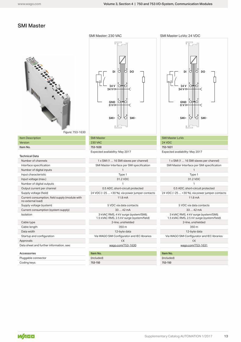
SMI Master
Item Description SMI Master SMI Master LoVoVersion 24 VDCItem No. 753-1630 753-1631
Expected availability: May 2017 Expected availability: May 2017Technical Data
Number of channels 1 x SMI (1 … 16 SMI slaves per channel) 1 x SMI (1 … 16 SMI slaves per channel)
Number of digital inputs 1 1Input characteristic Type 1 Type 1Input voltage (max.) 31.2 VDC 31.2 VDCNumber of digital outputs 1 1Output current per channel
no external load)11.8 mA 11.8 mA
Supply voltage (system)Current consumption (system supply) 33 … 42 mA 33 … 42 mAIsolation 3 kVAC RMS, 4 kV surge (system/SMI); 3 kVAC RMS, 4 kV surge (system/SMI);
Cable type 2-line, unshielded 2-line, unshieldedCable length 350 m 350 mData width 12-byte data 12-byte data
Approvals 1 1
Data sheet and further information, see: wago.com/753-1630 wago.com/753-1631
Accessories Item No. Item No.Pluggable connector (included) (included)Coding keys 753-150 753-150
SMI Master; 230 VAC SMI Master LoVo; 24 VDC
Figure: 753-1630
www.wago.com
14 Supplementary Catalog AUTOMATION 1/2017
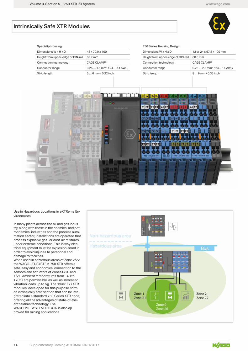
Volume 3, Section 5 | 750 XTR I/O System
Specialty Housing
Dimensions W x H x D 48 x 70.9 x 100
Height from upper-edge of DIN-rail
Connection technology CAGE CLAMP®
Conductor range 0.25 … 1.5 mm² / 24 … 14 AWG
Strip length 5 … 6 mm / 0.22 inch
Use in Hazardous Locations in eXTReme En-vironments
In many plants across the oil and gas indus-try, along with those in the chemical and pet-rochemical industries and the process auto-mation sector, installations are operated that process explosive gas- or dust-air mixtures under extreme conditions. This is why elec-trical equipment must be explosion-proof in order to avoid injuries to personnel and damage to facilities.When used in hazardous areas of Zone 2/22,
safe, easy and economical connection to the sensors and actuators of Zones 0/20 and
+70°C are permissible, as well as increased vibration loads up to 5g. The “blue” Ex i XTR modules, developed for this purpose, form an intrinsically safe section that can be inte-grated into a standard 750 Series XTR node,
WAGO-I/O-SYSTEM 750 XTR is also ap-proved for mining applications.
Intrinsically Safe XTR Modules
750 Series Housing Design
Dimensions W x H x D
Height from upper-edge of DIN-rail
Connection technology CAGE CLAMP®
Conductor range 0.25 … 2.5 mm² / 24 ... 14 AWG
Strip length 8 … 9 mm / 0.33 inch

www.wago.com
15Supplementary Catalog AUTOMATION 1/2017
Volume 3, Section 5 | 750 XTR I/O System
Standards and Rated ConditionsGeneral Specifications
Supply voltage (system)
Ambient temperature (operation)
Ambient temperature (storage)
Relative humidityIEC EN 60721-3-3 and E DIN 40046-721-3 (except wind-driven precipitation, water and ice formation)
Operating altitude
Pollution degree 2 per IEC 61131-2
Dielectric strength Per (EN 60870-2-1) • 510 VAC/775 VDCIsolation: rated surge voltage (EN 60079-11)• 1 kV; 1,5 kV between intrinsically safe and
non-intrinsically safe circuitsSurge:• 1 kV (L - L) / 2 kV (L - E)
Vibration resistance EN 60870-2-2, IEC 60721-3-1, -3
Shock resistance
EMC immunity to interference Per EN 61000-6-1, -2, EN 61131-2, marine applications, EN 60255-26, EN 60870-2-1, EN 61850-3, IEC 61000-6-5, IEEE 1613, VDEW: 1994
EMC emission of interference Per EN 61000-6-3, -4, EN 61131-2EN 60255-26, marine applicationsEN 60870-2-1 (industrial and residential areas)EN 61850-3 (industrial and residential areas)
Protection type IP20
Mounting position Horizontal (standing/lying) or vertical
Mounting type DIN-35 rail mounting
Housing material Polycarbonate, polyamide 6.6
Exposure to pollutants Per IEC 60068-2-42 and IEC 60068-2-43
Permissible SO2 contaminant concentra-
Permissible H2S contaminant concentra-
Connection technology CAGE CLAMP®
Conductor range; strip length Standard modules: Supply module:
0.25 … 2.5 mm²/24 … 14 AWG; 8 … 9 mm / 0.31 … 0.35 inch0.25 … 1.5 mm²/24 … 14 AWG; 5 … 6 mm / 0.2 … 0.24 inch
Current carrying capacity (power jumper contacts)
1 A

www.wago.com
16
24 V
0 V
Supplementary Catalog AUTOMATION 1/2017
Volume 3, Section 5 | 750 XTR I/O System
Supply Module; 24 VDC; Extreme, for Intrinsically Safe XTR Modules
Item Description Power SupplyVersion 24 VDC XTR for Ex i XTR ModulesItem No. 750-606/040-000 Expected availability: July 2017
Technical DataCurrent consumption (system supply)
Current carrying capacity (power jumper con-tacts)
1 ADC
Input voltage via PELV/SELV power supply units.
Fuse ElectronicData width 2 bits (input voltage failure, fuse triggered)Ambient temperature (operation)Dimensions W x H x D
Explosion protectionPower supply (input) Un = 24 VDC; Pmax = 29 W; Um = 253 VPower supply (output) Uo
protection level ia); In
Ex guideline EN/IEC 60079-0, -7, -11Approvals 1, 4 ATEX/IECExMarking ATEX: 4 II 3G Ex ec IIC T4 Gc
IECEx: Ex ec IIC T4 GcData sheet and further information, see: wago.com/750-606/040-000
The supply modules monitor the voltage supply of the downstream Ex-i segment and separate the intrinsi-cally safe from the non-intrinsically safe section of the I/O-System. Input and output sides are electrically isolated from each other.Note: If, due to load conditions, more than one supply module is required per station, four separation mod-
intrinsically safe sections.General information (e.g., installation regulations) on explosion protection is available in the WAGO-I/O-SYSTEM 750 XTR manuals!
Mini-WSB Quick Marking System, see Full Line Catalog, Volume 6
DIN rails and tool see Full Line Catalog, Volume 3
www.wago.com
17
24 V
0 V
--A
--
A
--A
--
A
9
10
11
12
13
14
15
16
3 ms
DI 1, DI 2 DI 5, DI 6
0 V 0 V
0 V 0 V
DI 3, DI 4 DI 7, DI 8
Supplementary Catalog AUTOMATION 1/2017
Volume 3, Section 5 | 750 XTR I/O System
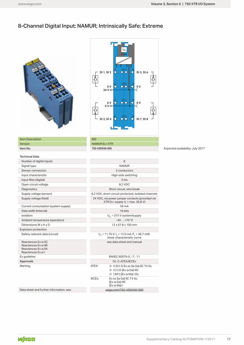
8-Channel Digital Input; NAMUR; Intrinsically Safe; Extreme
Item Description 8DIVersion NAMUR Ex i XTRItem No. 750-439/040-000 Expected availability: July 2017
Technical DataNumber of digital inputs 8Signal type NAMURSensor connection 2 conductorsInput characteristic High-side switching
3 msOpen-circuit voltageDiagnostics Short circuit, wire breakSupply voltage (sensor)
XTR Ex i supply Ui
Current consumption (system supply) 56 mAData width (internal) 16 bitsIsolation Um = 375 V system/supplyAmbient temperature (operation)Dimensions W x H x D
Explosion protectionSafety-relevant data (circuit) Uo o o
linear characteristic curve
Reactances Ex ia IIBReactances Ex ia IIA
see data sheet and manual
Ex guideline EN/IEC 60079-0, -7, -11Approvals 1, 4 ATEX/IECExMarking ATEX: 4 II 3(1) G Ex ec [ia Ga] IIC T4 Gc
4 II (1) D [Ex ia Da] IIIC 4 I (M1) [Ex ia Ma] I Dc
IECEx: Ex ec [ia Ga] IIC T4 Gc[Ex ia Da] IIIC[Ex ia Ma] I
Data sheet and further information, see: wago.com/750-439/040-000

www.wago.com
18
24 V
0 V
DO 1 DO 2
Supplementary Catalog AUTOMATION 1/2017
Volume 3, Section 5 | 750 XTR I/O System
2-Channel Digital Output; 24 VDC; Intrinsically Safe; Extreme
Item Description 2DOVersion 24 VDC Ex i XTRItem No. 750-535/040-000 Expected availability: July 2017
Technical DataNumber of digital outputs 2Signal typeOutput characteristic High-side switchingLoad type Resistive, inductive, lampsActuator connection 2 conductorsSwitching frequency (max.) 1 kHzActuator supply voltage
XTR Ex i supply Ui
Current consumption (system supply) 7 mAData width (internal) 2 bitsIsolation Um = 375 V system/supplyAmbient temperature (operation)Dimensions W x H x D
Explosion protectionSafety-relevant data (circuit) Uo o o
linear characteristic curve
Reactances Ex ia IIBReactances Ex ia IIA
see data sheet and manual
Ex guideline EN/IEC 60079-0, -7, -11Approvals 1, 4 ATEX/IECExMarking ATEX: 4 II 3(1) G Ex ec [ia Ga] IIC T4 Gc
4 II (1) D [Ex ia Da] IIIC 4 I (M1) [Ex ia Ma] I Dc
IECEx: Ex ec [ia Ga] IIC T4 Gc[Ex ia Da] IIIC[Ex ia Ma] I
Data sheet and further information, see: wago.com/750-535/040-000
Mini-WSB Quick Marking System, see Full Line Catalog, Volume 6
DIN rails and tool see Full Line Catalog, Volume 3

www.wago.com
19
24 V
0 V
9
10
11
12
13
14
15
16
DIN-35 rail
Shield Shield
UV 1, UV 2
0 V
AI 1, AI 2
UV 3, UV 4
0 V
AI 3, AI 4
Supplementary Catalog AUTOMATION 1/2017
Volume 3, Section 5 | 750 XTR I/O System
4-Channel Analog Input; 0/4 … 20 mA; Intrinsically Safe; Extreme
Item Description 4AIVersion 0/4-20mA Ex i XTRItem No. 750-486/040-000 Expected availability: July 2017
Technical DataNumber of analog inputs 4Signal type 0 mA ... 20 mA, 4 mA ... 20 mASignal characteristic Single-endedInput resistanceResolutionConversion timeMeasurement/output error (25 °C)
area
XTR Ex i supply Ui
Current consumption (system supply) 45 mATransmitter supply UV
Data width 4 x 16-bit data; 4 x 8-bit control/status (optional)Isolation Um = 375 V system/supplyAmbient temperature (operation)Dimensions W x H x D
Explosion protectionSafety-relevant data (circuit) Uo o o
linear characteristic curve
Reactances Ex ia IIBReactances Ex ia IIA
see data sheet and manual
Ex guideline EN/IEC 60079-0, -7, -11Approvals 1, 4 ATEX/IECExMarking ATEX: 4 II 3(1) G Ex ec [ia Ga] IIC T4 Gc
4 II (1) D [Ex ia Da] IIIC 4 I (M1) [Ex ia Ma] I Dc
IECEx: Ex ec [ia Ga] IIC T4 Gc[Ex ia Da] IIIC[Ex ia Ma] I
Data sheet and further information, see: wago.com/750-486/040-000

www.wago.com
20
24 V
0 V
9
10
11
12
13
14
15
16
DIN-35 rail
Shield
HART +
HART -
Supplementary Catalog AUTOMATION 1/2017
Volume 3, Section 5 | 750 XTR I/O System
2-Channel Analog Input; 4 … 20 mA HART; Intrinsically Safe; Extreme
Item Description 2AIVersion 4-20mA HART Ex i XTRItem No. 750-484/040-000 Expected availability: July 2017
Technical DataNumber of analog inputs 2 In addition to the analog signal processing, this
for parameterizing or recording side variables.Signal type 4 … 20 mASignal characteristic Single-endedResolution 12 bitsConversion time 10 msMeasurement/output error (25 °C)
area
XTR Ex i supply Ui
Current consumption (system supply) 25 mATransmitter supply UV
Data width 2 x 2-byte data; 2 x 2-byte data + 2n x 4-byte data (n = number of dynamic variables); 2 x 2-byte data +
6-byte mailboxIsolation Um = 375 V system/supplyAmbient temperature (operation)Dimensions W x H x D
Explosion protectionSafety-relevant data (circuit) Uo o o
linear characteristic curve
Reactances Ex ia IIBReactances Ex ia IIA
see data sheet and manual
Ex guideline EN/IEC 60079-0, -7, -11Approvals 1, 4 ATEX/IECExMarking ATEX: 4 II 3(1) G Ex ec [ia Ga] IIC T4 Gc
4 II (1) D [Ex ia Da] IIIC 4 I (M1) [Ex ia Ma] I Dc
IECEx: Ex ec [ia Ga] IIC T4 Gc[Ex ia Da] IIIC[Ex ia Ma] I
Data sheet and further information, see: wago.com/750-484/040-000
Mini-WSB Quick Marking System, see Full Line Catalog, Volume 6
DIN rails and tool see Full Line Catalog, Volume 3
www.wago.com
21
24 V
0 V
9
10
11
12
13
14
15
16
DIN-35 railShield
+R 1+R 2
RL 1RL 2
-R 1-R 2
Supplementary Catalog AUTOMATION 1/2017
Volume 3, Section 5 | 750 XTR I/O System
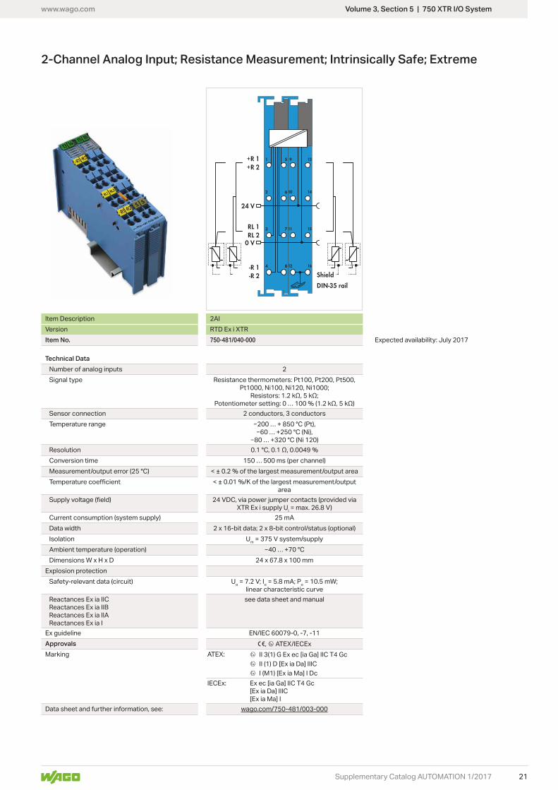
2-Channel Analog Input; Resistance Measurement; Intrinsically Safe; Extreme
Item Description 2AIVersion RTD Ex i XTRItem No. 750-481/040-000 Expected availability: July 2017
Technical DataNumber of analog inputs 2Signal type Resistance thermometers: Pt100, Pt200, Pt500,
Pt1000, Ni100, Ni120, Ni1000;
Sensor connection 2 conductors, 3 conductorsTemperature range
ResolutionConversion time 150 … 500 ms (per channel)Measurement/output error (25 °C)
area
XTR Ex i supply Ui
Current consumption (system supply) 25 mAData width 2 x 16-bit data; 2 x 8-bit control/status (optional)Isolation Um = 375 V system/supplyAmbient temperature (operation)Dimensions W x H x D
Explosion protectionSafety-relevant data (circuit) Uo o o
linear characteristic curve
Reactances Ex ia IIBReactances Ex ia IIA
see data sheet and manual
Ex guideline EN/IEC 60079-0, -7, -11Approvals 1, 4 ATEX/IECExMarking ATEX: 4 II 3(1) G Ex ec [ia Ga] IIC T4 Gc
4 II (1) D [Ex ia Da] IIIC 4 I (M1) [Ex ia Ma] I Dc
IECEx: Ex ec [ia Ga] IIC T4 Gc[Ex ia Da] IIIC[Ex ia Ma] I
Data sheet and further information, see: wago.com/750-481/003-000
www.wago.com
22
9
10
11
12
13
14
15
16
24 V
0 V
DIN-35 rail
Shield
0 … 20 mA
AO 1 AO 2
Supplementary Catalog AUTOMATION 1/2017
Volume 3, Section 5 | 750 XTR I/O System
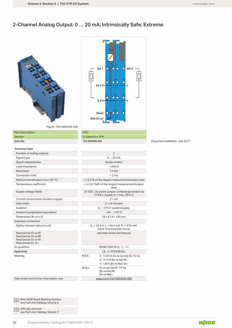
2-Channel Analog Output; 0 … 20 mA; Intrinsically Safe; Extreme
Item Description 2AOVersion 0-20mA Ex i XTRItem No. 750-585/040-000 Expected availability: July 2017
Technical DataNumber of analog outputs 2Signal type 0 … 20 mASignal characteristic Single-endedLoad impedanceResolution 12 bitsConversion timeMeasurement/output error (25 °C)
area
XTR Ex i supply Ui
Current consumption (system supply) 21 mAData width 2 x 16-bit dataIsolation Um = 375 V system/supplyAmbient temperature (operation)Dimensions W x H x D
Explosion protectionSafety-relevant data (circuit) Uo o o
linear characteristic curve
Reactances Ex ia IIBReactances Ex ia IIA
see data sheet and manual
Ex guideline EN/IEC 60079-0, -7, -11Approvals 1, 4 ATEX/IECExMarking ATEX: 4 II 3(1) G Ex ec [ia Ga] IIC T4 Gc
4 II (1) D [Ex ia Da] IIIC 4 I (M1) [Ex ia Ma] I Dc
IECEx: Ex ec [ia Ga] IIC T4 Gc[Ex ia Da] IIIC[Ex ia Ma] I
Data sheet and further information, see: wago.com/750-585/040-000
Figure: 750-585/040-000
Mini-WSB Quick Marking System, see Full Line Catalog, Volume 6
DIN rails and tool see Full Line Catalog, Volume 3

www.wago.com
23
9
10
11
12
13
14
15
16
24 V
0 V
--A
U/D (Gate), CLOCK
DO, 0 V
Supplementary Catalog AUTOMATION 1/2017
Volume 3, Section 5 | 750 XTR I/O System
Up/Down Counter; Intrinsically Safe; Extreme
Item Description Up/Down CounterVersion Ex i XTRItem No. 750-633/040-000 Expected availability: July 2017
Technical DataNumber of counters 1Number of outputs 1Sensor supply UV
10 μsSwitching frequency 20 Hz ... 50 kHzCounter depthOutput voltage
XTR Ex i supply Ui
Current consumption (system supply) 25 mAData width 1 x 32-bit data, 1 x 8-bit status/diagnosticsIsolation Um = 375 V system/supplyAmbient temperature (operation)Dimensions W x H x D
Explosion protectionSafety data – input Uo o o
linear characteristic curveInput reactances Ex ia IICInput reactances Ex ia IIBInput reactances Ex ia IIAInput reactances Ex ia I
see data sheet and manual
Safety data – output Uo o o linear characteristic curve
Output reactances Ex ia IICOutput reactances Ex ia IIBOutput reactances Ex ia IIAOutput reactances Ex ia I
see data sheet and manual
Ex guideline EN/IEC 60079-0, -7, -11Approvals 1, 4 ATEX/IECExMarking ATEX: 4 II 3(1) G Ex ec [ia Ga] IIC T4 Gc
4 II (1) D [Ex ia Da] IIIC 4 I (M1) [Ex ia Ma] I Dc
IECEx: Ex ec [ia Ga] IIC T4 Gc[Ex ia Da] IIIC[Ex ia Ma] I
Data sheet and further information, see: wago.com/750-633/040-000
www.wago.com
24
15 16
13 14
11 12
9 10
1000
LNK/ACT
852-110685
PWRRPSALM
7 8
5 6
3 4
1 2
T-Ports 1000 Mbps
Supplementary Catalog AUTOMATION 1/2017
Volume 3, Section 7 | Industrial Switches
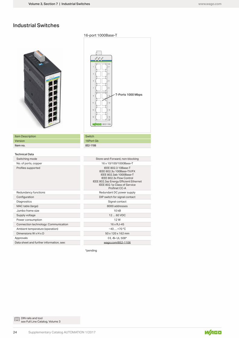
16-port 1000Base-T
Industrial Switches
Item Description SwitchVersion 16Port GbItem no. 852-1106
Technical DataSwitching mode Store-and-Forward, non-blockingNo. of ports, copper 16 x 10/100/1000Base-T
IEEE 802.3 10Base-TIEEE 802.3u 100Base-TX/FX
IEEE 802.3ab 1000Base-TIEEE 802.3x Flow Control
IEEE 802.1p Class of Service
Redundancy functions Redundant DC power supplyDIP switch for signal contact
Diagnostics Signal contactMAC table (large) 8000 addressesJumbo frame sizeSupply voltagePower consumption 12 WConnection technology: Communication 16 x RJ-45Ambient temperature (operation)Dimensions W x H x D 50 x 120 x 162 mm
Approvals 1, rData sheet and further information, see: wago.com/852-1106
DIN rails and tool see Full Line Catalog, Volume 3

www.wago.com
25Supplementary Catalog AUTOMATION 1/2017
Volume 3, Section 7 | Industrial Switches

www.wago.com
26
OUT 1IN
POWER
5
6
1
2
3
4
7
8
OUT 1+
GND 3
Us+
GND 1
IN+
GND 2
OUT 2+
GND 4OUT 2
<________ 94 mm/3.68 inch ________> 6 mm/0.23 inch
<________
97,
8 m
m/3
.85
inch ______>
_____________>
_>
Supplementary Catalog AUTOMATION 1/2017
857 Series
JUMPFLEX® Signal Conditioners
JUMPFLEX® -age input signal, 2 x current and voltage output
24 VDC supply voltage, 6 mm wide
Item No. Pack. Unit857-424 1
Technical DataConfiguration
Configuration DIP switchInput
Input signal
0 … 10 mA, 2 … 10 mA, 0 … 20 mA, 4 … 20 mA, 0 … 5 V, 1 … 5 V, 0 … 10 V, 2 … 10 V
Max. input signal 12 V, 24 mAOverload capacity 30 V, 50 mA
Input resistance
Output
Output signal
0 … 10 V, 2 … 10 V (calibrated configurable signals), 0 … 20 mA, 4 … 20 mA (calibrated configurable signals), max. 12 V, 24 mA
Load impedance
General SpecificationsNominal supply voltage US 24 VDCSupply voltage range US
Current input at 24 VDC
Limiting frequency 100 Hz / > 1 kHz (configurable via DIP switch)
Response time (T10-90) < 3.5 ms / < 300 sTransmission errorTemperature coefficientConformity marking 1
Standards/Approvals EN 61010-1, EN 61326-1Environmental Requirements
Ambient operating temperatureStorage temperature -40 … +85 °C
Safety and ProtectionTest voltage (input/output/supply) 3 kV (AC), 50 Hz, 1 minProtection type IP20
Connection and Mounting TypeConnection technology Push-in CAGE CLAMP®Conductor range
Solid 0.08 … 2.5 mm² / 28 … 14 AWGFine-stranded 0.34 … 2.5 mm² / 22 … 14 AWG
Strip length 9 … 10 mm / 0.35 … 0.39 inchDimensions and Weight
Dimensions (mm) W x H x D 6 x 97.8 x 94, height from upper-edge of DIN-railWeight 37.9 g
Short description:The 857-424 Signal Splitter converts, amplifies, fil-ters and electrically isolates analog standard signals. In addition, the input signal is split into two separate outputs.
Features:• Two configurable voltage/current outputs• Switchable limiting frequency• Safe 4-way isolation with 3 kV test voltage per
EN 61010-1
Overview of icons, see page 56
Volume 4, Section 3 | JUMPFLEX®

www.wago.com
27Supplementary Catalog AUTOMATION 1/2017
Volume 4, Section 3 | JUMPFLEX®
● = ON
857-424
DIP Switch Adjustability
Default Settings
Input 0 … 20 mA
Output Signal 1 0 … 10 V
Output Signal 2 0 … 10 V
Max. Operating Frequency > 1 kHz
DIP Switch S1 (4 positions)
Input Signal Max. Operating Frequency
1 2 3 4
● 0 … 20 mA > 1 kHz
● ● 4 … 20 mA ● 100 Hz
● ● 0 … 10 mA
● ● ● 2 … 10 mA
0 … 10 V
● 2 … 10 V
● 0 … 5 V
● ● 1 … 5 V
DIP Switch S2 (2 positions)
Output Signal 1
1 2
0 … 10 V
● 2 … 10 V
● 0 … 20 mA
● ● 4 … 20 mA
DIP Switch S3 (2 positions)
Output Signal 2
1 2
0 … 10 V
● 2 … 10 V
● 0 … 20 mA
● ● 4 … 20 mA

www.wago.com
28
<________ 94 mm/3.68 inch ________> 6 mm/0.23 inch
<________
97,
8 m
m/3
.85
inch ______>
_____________>
_>
Supplementary Catalog AUTOMATION 1/2017
857 Series
JUMPFLEX® Signal ConditionersVoltage Signal Conditioner
JUMPFLEX® Voltage Signal Conditioner, current input signal for AC and DC voltages, current and
via software/DIP switch, 24 VDC supply voltage, 6 mm wide
Item No. Pack. Unit857-560 1
Short description:The 857-560 Voltage Signal Conditioner measures AC and DC voltages up to 300 V AC/DC and con-verts the input signal into an analog standard signal at the output.
Features:• Two isolated measurement inputs for 30 V and
300 V AC/DC• True RMS measurement or arithmetic mean value• A digital signal output reacts to configured mea-
surement range limits (switching ON/OFF delay and threshold value switch function configurable with up to two threshold values)
• Switchable filter function• Safe 3-way isolation with 3 kV test voltage per
EN 61010-1
Specialty functions:
Technical DataConfiguration
Configuration DIP switch, interface configuration software, interface configuration app
InputInput signal 300 or 30 VAC/DCResponse threshold IN 1: 300 mV, IN 2: 30 mVInput resistanceFrequency range 10 … 100 Hz (AC)Overload capacity IN 1: 600 V; IN 2: 60 V (permanent)Resolution IN 1: 30 mV, IN 2: 3 mV
Output
Output signal
± 0 … 20 mA, 4 … 20 mA,± 0 … 10 mA, 2 … 10 mA± 0 … 10 V, 2 … 10 V,± 0 … 5 V, 1 … 5 V
Load impedance
Output – DigitalMax. switching voltage Supply voltage appliedMax. continuous current 100 mA
General SpecificationsNominal supply voltage US 24 VDCSupply voltage range US
Current input at 24 VDC 46 mA + IDO
Measuring procedure Effective value (RMS) or arithmetic mean valueLimiting frequency 2 kHzResponse time (typ.), signal cycle duration + 1 msResponse time (T10-90) 60 msTemperature coefficientLinearity errorMeasurement errorConformity marking 1
Standards/Approvals EN 61010-1, EN 61326-1Environmental Requirements
Ambient operating temperatureStorage temperature -40 … +85 °C
Safety and ProtectionTest voltage (input/output/supply) 3 kV (AC), 50 Hz, 1 minProtection type IP20
Connection and Mounting TypeConnection technology Push-in CAGE CLAMP®Conductor range
Solid 0.08 … 2.5 mm² / 28 … 14 AWGFine-stranded 0.34 … 2.5 mm² / 22 … 14 AWG
Strip length 9 … 10 mm / 0.35 … 0.39 inchDimensions and Weight
Dimensions (mm) W x H x D 6 x 97.8 x 94, height from upper-edge of DIN-railWeight 55 g
Overview of icons, see page 56
Volume 4, Section 3 | JUMPFLEX®

www.wago.com
29Supplementary Catalog AUTOMATION 1/2017
Volume 4, Section 3 | JUMPFLEX®
● = ON
857-560
DIP Switch Adjustability
DIP Switch S1
Measuring Range Under� ow
Measuring Range Over� owDigit Output DO/
Signaling8 9 10
Lower limit of measuring range −5 %* Upper limit of measuring range +2.5 %* DO Us+ switching
● Lower limit of measuring range Upper limit of measuring range +2.5 % ● DO GND switching
● Lower limit of measuring range Upper limit of measuring range
● ● Lower limit of measuring range Upper limit of measuring range
*per NAMUR NE 43
Default Setting
All DIP switches are in “OFF“ position for delivery.
Input
Input 300 V
Measuring Method RMS
Filter O�
Output
Output Signal 0 ... 20 mA
Measuring Range Under� ow 0 mA
Measuring Range Over� ow 20.5 mA
Overcurrent 21 mA
Digital Output DO Us+ switching
DIP Switch S1
1 2 Input 3 Measuring Method 4 Filter
300 V RMS O�
● 150 V ● Arithmetic mean value ● Active
● 30 V
● ● 15 V
DIP Switch S1
5 6 7 Output Signal Range
(+/-) 0 ... 20 mA
● 4 ... 20 mA
● (+/-) 0 ... 10 V
● ● 2 ... 10 V
● (+/-) 0 ... 10 mA
● ● 2 ... 10 mA
● ● (+/-) 0 ... 5 V
● ● ● 1 ... 5 V
Digital Output DO/Signaling
The digital output (DO) signals error messages and can be con� gured as follows: 24 V → 0 V/0 V → 24 V
Filter
The � lter function allows a low-pass � lter to be switched on in order to mask or “smooth out” oscillating measured values (e.g., during trailing edge � ows).

www.wago.com
30
<________ 94 mm/3.68 inch ________> 6 mm/0.23 inch
<________
97,
8 m
m/3
.85
inch ______>
_____________>
_>
Supplementary Catalog AUTOMATION 1/2017
857 Series
JUMPFLEX® Signal ConditionersPower Signal Conditioner
JUMPFLEX® Power Signal Conditioner, current and voltage input signal, current and voltage
software/DIP switch, 24 VDC supply voltage, 6 mm wide
Item No. Pack. Unit857-569 1
Short description:The 857-569 Power Signal Conditioner measures both AC/DC voltages and currents, converting the input signal into an analog standard signal at the output. Measured value processing can be switched between effective, apparent or reactive power, and phase angle.
Features:• Two isolated measurement inputs for AC and DC
voltages and AC and DC currents• RMS measurement• A digital signal output reacts to configured mea-
surement range limits (switching ON/OFF delay and threshold value switch function configurable with up to two threshold values)
• Switchable filter function • Safe 3-way isolation with 3 kV test voltage per
EN 61010-1
Specialty functions:
Technical DataConfiguration
Configuration DIP switch, interface configuration software, interface configuration app
InputInput signal IN 1: 300 V AC/DC, IN 2: 5 A AC/DC
Response threshold IN 1: 300 mVIN 2: 10 mA
Resolution IN 1: 30 mVIN 2: 1 mA
Input resistance
Frequency range 15 … 70 Hz (AC)Overload capacity 10 A AC/DC (permanent)
Output
Output signal
0 … 10 mA, 2 … 10 mA, 0 … 20 mA, 4 … 20 mA, 0 … 5 V, 1 … 5 V, 0 … 10 V, 2 … 10 V(can be inverted, also bipolar)
Load impedance
Output – DigitalMax. switching voltage Supply voltage appliedMax. continuous current 100 mA
General SpecificationsNominal supply voltage US 24 VDCSupply voltage range US
Current input at 24 VDCMeasuring procedure RMS measurementMeasured variables Effective/apparent/reactive power, power factorLimiting frequency 2 kHzResponse time (typ.), signal cycle duration +1 msResponse time (T10-90) 100 msTemperature coefficientLinearity error
Measurement error (relative to measurement range upper limit)
Conformity marking 1
Standards/Approvals EN 61010-1, EN 61326-1Environmental Requirements
Ambient operating temperatureStorage temperature -40 … +85 °C
Safety and ProtectionTest voltage (input/output/supply) 3 kV (AC), 50 Hz, 1 min.Protection type IP20
Connection and Mounting TypeConnection technology Push-in CAGE CLAMP®Conductor range
Solid 0.08 … 2.5 mm² / 28 … 14 AWGFine-stranded 0.34 … 2.5 mm² / 22 … 14 AWG
Strip length 9 … 10 mm / 0.35 … 0.39 inchDimensions and Weight
Dimensions (mm) W x H x D 6 x 97.8 x 94, height from upper-edge of DIN-railWeight 55 g
Overview of icons, see page 56
Volume 4, Section 3 | JUMPFLEX®

www.wago.com
31Supplementary Catalog AUTOMATION 1/2017
Volume 4, Section 3 | JUMPFLEX®
● = ON
857-569DIP Switch Adjustability
DIP Switch S1
Measuring Range Under� ow
Measuring Range Over� owDigit Output DO/
Signaling8 9 10
Lower limit of measuring range −5 %* Upper limit of measuring range +2.5 %* DO Us+ switching
● Lower limit of measuring range Upper limit of measuring range +2.5 % ● DO GND switching
● Lower limit of measuring range Upper limit of measuring range *per NAMUR NE 43
● ● Lower limit of measuring range Upper limit of measuring range
Default Setting
All DIP switches are in “OFF“ position for delivery.
Input
Input Power
Measuring Method Active power
Filter O�
Output
Output Current
Output Signal Range 0 ... 20 mA
Measuring Range Under� ow 0 mA
Measuring Range Over� ow 20.5 mA
Overcurrent 21 mA
Digital Output DO Us+ switching
DIP Switch S1
1 2 Input 3 4 Filter
Active power O� O�
● Apparent power ● ● Active
● Reactive power
● ● Power factor
Digital Output DO/Signaling
The digital output (DO) signals error messages and can be con� gured as follows: 24 V → 0 V/0 V → 24 V
Filter
The � lter function allows a low-pass � lter to be switched on in order to mask or “smooth out” oscillating measured values (e.g., during trailing edge � ows).
DIP Switch S1
5 6 7 Output Signal Range
0 ... 20 mA
● 4 ... 20 mA
● 0 ... 10 V
● ● 2 ... 10 V
● 0 ... 10 mA
● ● 2 ... 10 mA
● ● 0 ... 5 V
● ● ● 1 ... 5 V

www.wago.com
32
OUT
IN
5
6
1
2
3
4
7
8
OUT+
GND 1
Us+
GND 2 POWER
<________ 94 mm/3.68 inch ________> 6 mm/0.23 inch
<________
97,
8 m
m/3
.85
inch ______>
_____________>
_>
Supplementary Catalog AUTOMATION 1/2017
857 Series
JUMPFLEX® Signal ConditionersLoop-Powered RTD Temperature Signal Conditioner
JUMPFLEX® Loop-Powered RTD Temperature Signal Conditioner for Pt Sensors, current output
output, 6 mm wideItem No. Pack. Unit857-815 1
Short description:The 857-815 Loop-Powered RTD Temperature Sig-nal Conditioner records Pt100, Pt200, Pt500 and
-ing the temperature signal into an analog standard signal on the output side.
Features:• No additional supply voltage required• For Pt100, Pt200, Pt500 and Pt1000 sensors, as
well as resistors up to 4.5 kOhm• 2-, 3-, and 4-wire connection technology• Switching between measurement ranges is
calibrated• Detects sensor wire break/short circuit• Safe 3-way isolation with 3 kV test voltage per
EN 61010-1
Technical DataConfiguration
Configuration DIP switchInput
Input signal Pt sensors and resistorsSensor types Pt100, Pt200, Pt500, Pt1000Sensor connection 2-wire, 3-wire, 4-wire (configurable)Temperature rangeSensor power supply < 0.5 mAResistor input
Output
Output signal 4 … 20 mA,20 … 4 mA
Load impedance Refresh cycle < 1 s (per NAMUR NE 89)
General SpecificationsNominal supply voltage US 8 … 30 V (power derived from the output circuit)Min. measuring span 50 KTransmission errorTransmission error of the preset measuring spanTemperature coefficientConformity marking 1
Standards/Approvals EN 61010-1, EN 61326-1Environmental Requirements
Ambient operating temperatureStorage temperature -40 … +85 °C
Safety and ProtectionTest voltage (input/output/supply) 3 kV (AC), 50 Hz, 1 minProtection type IP20
Connection and Mounting TypeConnection technology Push-in CAGE CLAMP®Conductor range
Solid 0.08 … 2.5 mm² / 28 … 14 AWGFine-stranded 0.34 … 2.5 mm² / 22 … 14 AWG
Strip length 9 … 10 mm / 0.35 … 0.39 inchDimensions and Weight
Dimensions (mm) W x H x D 6 x 97.8 x 94, height from upper-edge of DIN-railWeight 39 g
Overview of icons, see page 56
Volume 4, Section 3 | JUMPFLEX®

www.wago.com
33Supplementary Catalog AUTOMATION 1/2017
Volume 4, Section 3 | JUMPFLEX®
● = ON
857-815
DIP Switch Adjustability
DIP Switch S2
Output Signal
Start Temperature
Output Signal
End Temperature
1 2 3 4 °C °F 5 6 7 8 9 10 °C °F 5 6 7 8 9 10 °C °F 5 6 7 8 9 10 °C °F 5 6 7 8 9 10 °C °F
0 32 100 212 ● 75 167 ● 210 410 ● ● 475 887
● −200 −328 ● 0 32 ● ● 80 176 ● ● 220 428 ● ● ● 500 932
● −175 −283 ● 5 41 ● ● 85 185 ● ● 230 446 ● ● ● 525 997
● ● −150 −238 ● ● 10 50 ● ● ● 90 194 ● ● ● 240 464 ● ● ● ● 550 1022
● −125 −193 ● 15 59 ● ● 95 203 ● ● 250 482 ● ● ● 575 1067
● ● −100 −148 ● ● 20 68 ● ● ● 100 212 ● ● ● 260 500 ● ● ● ● 600 1112
● ● −90 −130 ● ● 25 77 ● ● ● 110 230 ● ● ● 270 518 ● ● ● ● 625 1157
● ● ● −80 −112 ● ● ● 30 86 ● ● ● ● 120 248 ● ● ● ● 280 536 ● ● ● ● ● 650 1202
● −70 −94 ● 35 95 ● ● 130 266 ● ● 290 554 ● ● ● 675 1247
● ● −60 −76 ● ● 40 104 ● ● ● 140 284 ● ● ● 300 572 ● ● ● ● 700 1292
● ● −50 −58 ● ● 45 113 ● ● ● 150 302 ● ● ● 325 617 ● ● ● ● 725 1337
● ● ● −40 −40 ● ● ● 50 122 ● ● ● ● 160 320 ● ● ● ● 350 662 ● ● ● ● ● 750 1382
● ● −30 −22 ● ● 55 131 ● ● ● 170 338 ● ● ● 375 707 ● ● ● ● 775 1427
● ● ● −20 −4 ● ● ● 60 140 ● ● ● ● 180 356 ● ● ● ● 400 752 ● ● ● ● ● 800 1472
● ● ● −10 14 ● ● ● 65 149 ● ● ● ● 190 374 ● ● ● ● 425 797 ● ● ● ● ● 825 1517
● ● ● ● 0 32 ● ● ● ● 70 158 ● ● ● ● ● 200 392 ● ● ● ● ● 450 842 ● ● ● ● ● ● 850 1562
The minimum distance from the start temperature to the end temperature may not fall short of 50K degrees on the Celsius (C) scale or 122K degrees on the Fahrenheit (F) scale.
DIP Switch S1
Sensor Connection
Sensor Type Output Signal N. C.
Measuring Range
Under� ow
Measuring Range
Over� ow
Wire Break Short Circuit
1 2 3 4 5 6 7 8 9 10
2-wire Pt100 4 … 20 mA Lower limit of output range −5 % *
Upper limit of output range +2.5 % *
Upper limit of output range +5 % *
Lower limit of output range −12.5 % *● 3-wire ● Pt200 ● 20 … 4 mA
● 4-wire ● Pt500●
Lower limit of output range
Upper limit of output range +2.5 %
Upper limit of output range +5 %
Lower limit of output range● ● 2-wire ● ● Pt1000
● 1 kΩ●
Lower limit of output range
Upper limit of output range
Upper limit of output range +5 %
Upper limit of output range +5 %● ● 4.5 kΩ
● ●Lower limit of output
rangeUpper limit of output
rangeLower limit of output
rangeLower limit of output
range
*per NAMUR NE 43
Default Settings
All DIP switches are in “OFF“ position for delivery.
Sensor connection 2-wire
Sensor type Pt100
Start temperature 0 °C
End temperature 100 °C
Output signal 4 … 20 mA
Measuring range under� ow 3.8 mA
Measuring range over� ow 20.5 mA
Wire break 21 mA
Short circuit 3.5 mA

www.wago.com
34 Supplementary Catalog AUTOMATION 1/2017
Technical DataInput
Rated continuous thermal current Icth 1.2 x IN
Rated short-time thermal current Ith 60 x IN (max. 100 kA), 1 sMax. operating voltage Um 1.2 kVrms
Rated frequency 50 … 60 Hz
Overcurrent limiting factor FS5 or FS10 (type dependent, see type plate inscription)
General SpecificationsConformity marking 1
Standards/Approvals EN 61869-1; EN 61869-2Y (Recognized Components) E356480
Environmental RequirementsAmbient operating temperatureStorage temperatureMax. operating altitude 1000 m
Safety and ProtectionTest voltage 6 kVrms AC / 50 Hz / 1 minInsulation class E
ConnectionConnection technology CAGE CLAMP®Conductor range 0.08 … 4 mm² / 28 … 12 AWGStrip length 9 … 10 mm / 0.35 … 0.39 inch
Short description:The 855 Series Plug-In Current Transformers are inductive, single-conductor current transformers, that function according to the transformer principle. Due to the measurement principle used, these cur-rent transformers are exclusively designed for AC network applications.
Features:• Screwless CAGE CLAMP® connection
technology• Several mounting options available• Vibration- and shock-resistant• High mechanical retention forces• High current-carrying capacity•
the nominal primary current• Low-voltage current transformer for
operating voltages up to 1.2 kV• Can be used in 690 V power networks• UL recognized components
855 Series
Plug-In Current Transformers with CAGE CLAMP® Connection
Volume 4, Section 4 | Current and Energy Measurement Technology

www.wago.com
35Supplementary Catalog AUTOMATION 1/2017
Plug-In Current Transformer Primary Rated Current
SecondaryRated current
Rated Power
Accuracy Class Item No. Pack.
Unit250 A 1 A 5 VA 1 855-401/250-501 1
Plug-In Current Transformer Primary Rated Current
SecondaryRated current
Rated Power
Accuracy Class Item No. Pack.
Unit400 A 1 A 10 VA 1 855-501/400-1001 1
600 A 1 A 10 VA 1 855-501/600-1001 1
800 A 1 A 10 VA 1 855-501/800-1001 1
Plug-In Current Transformer Primary Rated Current
SecondaryRated current
Rated Power
Accuracy Class Item No. Pack.
Unit1000 A 1 A 10 VA 1 855-801/1000-1001 1
Volume 4, Section 4 | Current and Energy Measurement Technology
855-4xx/xxxx-xxxx
Busbar 1: 40 x 10 mm
Busbar 2: 30 x 15 mmm
Round cable: 32 mm
35 70
91
.15
855-5xx/xxxx-xxxx
Busbar 1: 50 x 12 mm
Busbar 2: 40 x 30 mm
Round cable: 44 mm
10
5.2
5
3585
855-8xx/xxxx-xxxx
Busbar 1: 80 x 10 mm
Busbar 2: 60 x 30 mm
Round cable: 55 mm
35120
13
4.4

www.wago.com
36 Supplementary Catalog AUTOMATION 1/2017
855 SeriesCurrent and Voltage Tap for 95 mm² High-Current Through Terminal Block (285-195)
Current and voltage tap for 95 mm² high-current through terminal block (285-195)
Item No. Pack. Unit855-951/250-000 1
Short description:The 855-951/250-000 Current and Voltage Tap for 95 mm² high-current through terminal block pro-vides the ideal basis for successful energy manage-ment, because current and voltage are required wherever electrical power is measured. A combina-tion of current transformer and voltage tap, the 855-951 can quickly and easily be inserted into the jumper slot of the 95 mm² high-current through terminal block (285-195).
An integrated fuse provides protection for energy measurement devices connected in the down-stream circuit. An integrated current transformer (conversion ratio: 250 A/1 A) allows precise current measurement per EN 61869-2 (accuracy class: 0.5).
The current output connectors are marked with S1 (black) and S2 (red). Both termination and removal of fine-stranded conductors is performed via push-buttons. The 5-pole configuration (2 x S1 and 3 x S2) provides the following advantages:
• Current transformer (S1 and S2) can be short cir-cuited via jumper (2000-402)
• Direct ‘Y’ point jumper on current transformer
The voltage is connected using a redundant terminal block.
Additionally, the current and voltage tap can be marked either using continuous marking strips or via WMB Multi Marking System.
Features:• Power data can be directly tapped into the power
supply• Easy installation – simply insert the tap into the
jumper slot of the 95 mm² high-current through terminal block (285-195)
• Integrated 250 A/1 A current transformer• Accuracy class: 0.5• Fuse-protected voltage path
Technical DataInput (current transformer)
Primary rated current Ipr 250 ARated continuous thermal current Icth 250 ARated short-time thermal current Ith 15 kA / 1 sRated surge current Idyn 37.5 kARated frequency fr 50 … 60 Hz
m 0.72 kVRated insulation level 3 kV
Output (current transformer)Secondary Rated Current Isr 1 AAccuracy class 0.5Rated power Sr 0.2 VA
Output (voltage tap)Nominal voltage
Fuse (voltage path) 2 A, 450 V, F, 70 kA, 5 x 25 mm, (SIBA Art. No. 7008913.2)
Safety and ProtectionProtection type IP20
Connection and Mounting TypeFeedthrough for measurement conductor 16 mm Ø (max.)
Connection technology Current output: WAGO 250 SeriesVoltage output: WAGO 2624 Series
Conductor range
Current output: 0.2 … 1.5 mm² / 24 … 10 AWGVoltage output: 0.2 … 4 mm² / 24 … 14 AWG
Strip length
Current output: 8 … 9 mm / 0.31 … 0.35 inchVoltage output: 10 … 12 mm / 0.39 … 0.47 inch
Mounting type via jumper slot of the 2-conductor high-current through terminal block (285-195)
Dimensions and WeightDimensions (mm) W x H x D 25 x 73 x 94Weight
Conformity marking 1
Standards/Approvals EN 61869-2
Volume 4, Section 4 | Current and Energy Measurement Technology

www.wago.com
37Supplementary Catalog AUTOMATION 1/2017

www.wago.com
38 Supplementary Catalog AUTOMATION 1/2017
Features:• Economical power supply for standard applica-
tions• Natural convection cooling when horizontally
mounted• Enclosed for use in control cabinets• Fast and tool-free termination via lever-actuated
terminals with push-in connection technology• DC OK contact• Parallel operation• Electrically isolated output voltage (SELV) per EN
60950-1/UL 60950-1; PELV per EN 60204-1
Technical DataInput
Nominal input voltage Ui nom 400 ... 480 VACInput voltage range 325 … 575 VAC, 560 … 700 VDCFrequency 47 … 63 HzInput peak current < 30 A (at 400 VAC)Discharge current < 3.5 mAPower factorMains failure hold-up time > 10 ms (at 400 VAC and nominal load)
OutputNominal output voltage Uo nom 24 VDC (default), SELVOutput voltage range 24 … 28 VDC adjustableAdjustment accuracyResidual ripple < 150 mVpp
Overload behaviorConstant power (in overload range: 1.05 … 1.4 x Io); shutdown and automatic restart in the event of a short circuit
Fuse ProtectionRecommended backup fuseOvervoltage protection Via varistor at primary circuit
Environmental RequirementsAmbient temperatureStorage temperatureRelative humidityClimatic category 3K3 (per EN 60721)DeratingPollution degree 2Overvoltage category IIITemperature coefficientMTBF > 200,000 h
Safety and ProtectionProtection class IProtection type IP20 per EN 60529Short-circuit-protection YesOpen-circuit proof YesFeedback voltage 30 V (max.)Parallel operation YesSeries operation Yes, max. 2 power suppliesVibration resistance 1g (per EN 60068-2-6)Shock resistance 15g (per EN 60068-2-27)
Isolation voltage
1.5 kVAC for input side and ground; 3.0 kVAC for input and output side; 0.5 kVAC for output side and ground; 0.5 kVAC for output side and DC OK contact
SELV per EN 60950-1Connection and Mounting Type
Connection technology CAGE CLAMP® (input/output); picoMAX® (signaling)
Conductor range Input/output: 0.5 … 6 mm² / 20 … 10 AWG Signaling: 0.2 … 1.5 mm² / 24 … 14 AWG
Strip length Input/output: 11 … 12 mm / 0.43 … 0.47 inch Signaling: 8 … 9 mm / 0.31 … 0.35 inch
Standards/Approvals
Standards/Approvals 1
Volume 4, Section 5 | EPSITRON® Power Supplies
787 Series
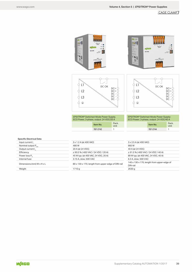
Switched-Mode Power Supply, 3-Phase EPSITRON® ECO Power
L
H
WL
H
W
www.wago.com
39
L1
L2
L3
DC+DC+DC -DC -DC -
DC OK L1
L2
L3
DC+DC+DC -DC -DC -
DC OK
Supplementary Catalog AUTOMATION 1/2017
Volume 4, Section 5 | EPSITRON® Power Supplies
EPSITRON® Switched-Mode Power Supply, ECO Power, 3-phase, output: 24 VDC/20 A
Item No. Pack. Unit
787-2742 1
EPSITRON® Switched-Mode Power Supply; ECO Power; 3-phase, output: 24 VDC/40 A
Item No. Pack. Unit
787-2744 1
Specific Electrical DataInput current Ii 3 x 1.2 A (at 400 VAC) 3 x 2.5 A (at 400 VAC)Nominal output Pout 480 W 960 WOutput current Io 20 A (at 24 VDC) 40 A (at 24 VDC)EfficiencyPower loss PV 45 W typ. (at 400 VAC, 24 VDC, 20 A) 89 W typ. (at 400 VAC, 24 VDC, 40 A)Internal fuse 3.15 A, slow, 500 VAC 6.3 A, slow, 500 VAC
Dimensions (mm) W x H x L 80 x 130 x 170, length from upper-edge of DIN-rail 140 x 130 x 170, length from upper-edge of DIN-rail
Weight 1710 g 2630 g

www.wago.com
40
<________ 94 mm/3.68 inch ________> 6 mm/0.23 inch
<________
97,
8 m
m/3
.85
inch ______>
_____________>
_>
Supplementary Catalog AUTOMATION 1/2017
787 Series
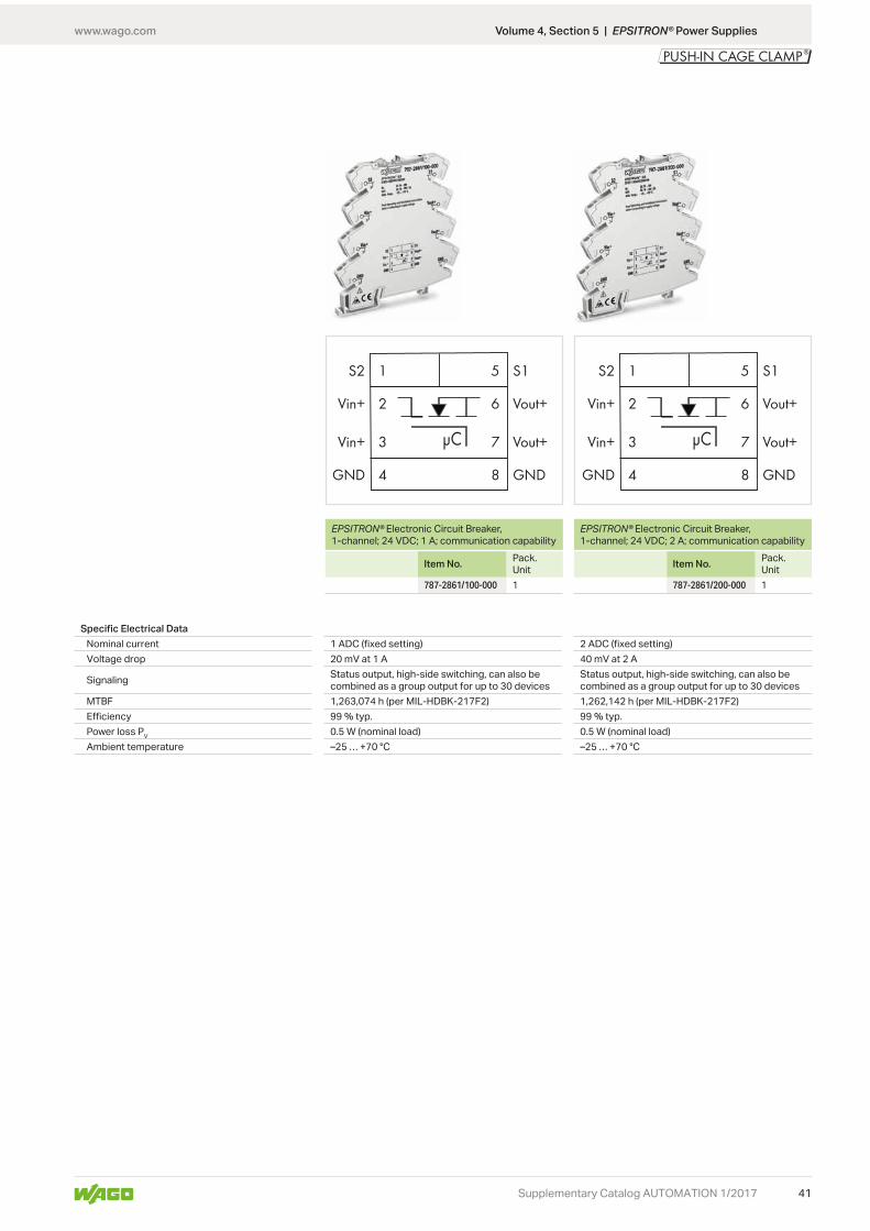
Electronic Circuit Breakers (ECBs) EPSITRON®
Features:• Space-saving ECB with one channel• Reliably and safely trips in the event of an over-
load and short circuit on the secondary side• • Enables the use of an economical, standard pow-
er supply• Minimizes wiring via two voltage outputs and max-
imizes commoning options on both input and out-put sides (e.g., commoning of the output voltage on 857 and 2857 Series devices)
• Status signal – as single or group message• Reset, switch on/off via remote input or local
switch• Prevents power supply overload due to total in-
rush current thanks to time-delayed switching on
Technical DataInput
Nominal input voltage Ui nom
Input voltage range 18 … 30 VDCOutput
Nominal output voltage Uo nom Uo nom – voltage dropTrip time Load-dependent (4 ms ... 100 s)Switch-on capacity
Switch-on behavior Time-delayed channel switching(load-dependent min. 2 ms/max. 200 ms)
Active current limitation NoStatus indication LED (green/red/orange)
Remote input 18 … 30 VDC signal, switches on/off and resets the channel
Fuse ProtectionInternal fuse
Environmental RequirementsStorage temperatureRelative humidityDerating No derating
Safety and ProtectionTest voltage 500 VDC (bus modules to housing)Protection class IIIReverse voltage protection NoProtection type IP20 per EN 60529Overvoltage protection Via 33 V suppressor diode at inputSeries connection of several devices Not permittedParallel operation of single channels Not permitted
Connection and Mounting TypeConnection technology Push-in CAGE CLAMP® (WAGO 857 Series)
Conductor range Solid: 0.08 … 2.5 mm² / 28 … 14 AWGFine-stranded: 0.34 … 2.5 mm² / 22 … 14 AWG
Strip length 9 … 15 mm / 0.35 … 0.39 inchMounting type DIN-rail mount (EN 60715)
Dimensions and WeightDimensions (mm) W x H x D 6 x 97.8 x 94, height from upper-edge of DIN-railWeight 40 g
General Specifications
Standards/Approvals
Volume 4, Section 5 | EPSITRON® Power Supplies
www.wago.com
41
S1
Vout+
Vout+
GND
S2
Vin+
Vin+
GND
5
6
1
2
3
4
7
8
μC
S1
Vout+
Vout+
GND
S2
Vin+
Vin+
GND
5
6
1
2
3
4
7
8
μC
Supplementary Catalog AUTOMATION 1/2017
EPSITRON® Electronic Circuit Breaker, 1-channel; 24 VDC; 1 A; communication capability
Item No. Pack. Unit
787-2861/100-000 1
EPSITRON® Electronic Circuit Breaker, 1-channel; 24 VDC; 2 A; communication capability
Item No. Pack. Unit
787-2861/200-000 1
Specific Electrical DataNominal current 1 ADC (fixed setting) 2 ADC (fixed setting)Voltage drop 20 mV at 1 A 40 mV at 2 A
Signaling Status output, high-side switching, can also be combined as a group output for up to 30 devices
Status output, high-side switching, can also be combined as a group output for up to 30 devices
MTBF 1,263,074 h (per MIL-HDBK-217F2) 1,262,142 h (per MIL-HDBK-217F2)EfficiencyPower loss PV 0.5 W (nominal load) 0.5 W (nominal load)Ambient temperature –25 … +70 °C –25 … +70 °C
Volume 4, Section 5 | EPSITRON® Power Supplies

www.wago.com
42
S1
Vout+
Vout+
GND
S2
Vin+
Vin+
GND
5
6
1
2
3
4
7
8
μC
S1
Vout+
Vout+
GND
S2
Vin+
Vin+
GND
5
6
1
2
3
4
7
8
μC
Supplementary Catalog AUTOMATION 1/2017
EPSITRON® Electronic Circuit Breaker, 1-channel; 24 VDC; 4 A; communication capability
Item No. Pack. Unit
787-2861/400-000 1
EPSITRON® Electronic Circuit Breaker, 1-channel; 24 VDC; 6 A; communication capability
Item No. Pack. Unit
787-2861/600-000 1
Specific Electrical DataNominal current 4 ADC (fixed setting) 6 ADC (fixed setting)Voltage drop 80 mV at 1 A 120 mV at 6 A
Signaling Status output, high-side switching, can also be combined as a group output for up to 30 devices
Status output, high-side switching, can also be combined as a group output for up to 30 devices
MTBF 1,258,733 h (per MIL-HDBK-217F2) 1,253,313 h (per MIL-HDBK-217F2)EfficiencyPower loss PV 0.5 W (nominal load) 0.5 W (nominal load)Ambient temperature –25 … +70 °C
Volume 4, Section 5 | EPSITRON® Power Supplies
www.wago.com
43
S1
Vout+
Vout+
GND
S2
Vin+
Vin+
GND
5
6
1
2
3
4
7
8
μC
S1
Vout+
Vout+
GND
S2
Vin+
Vin+
GND
5
6
1
2
3
4
7
8
μC
Supplementary Catalog AUTOMATION 1/2017
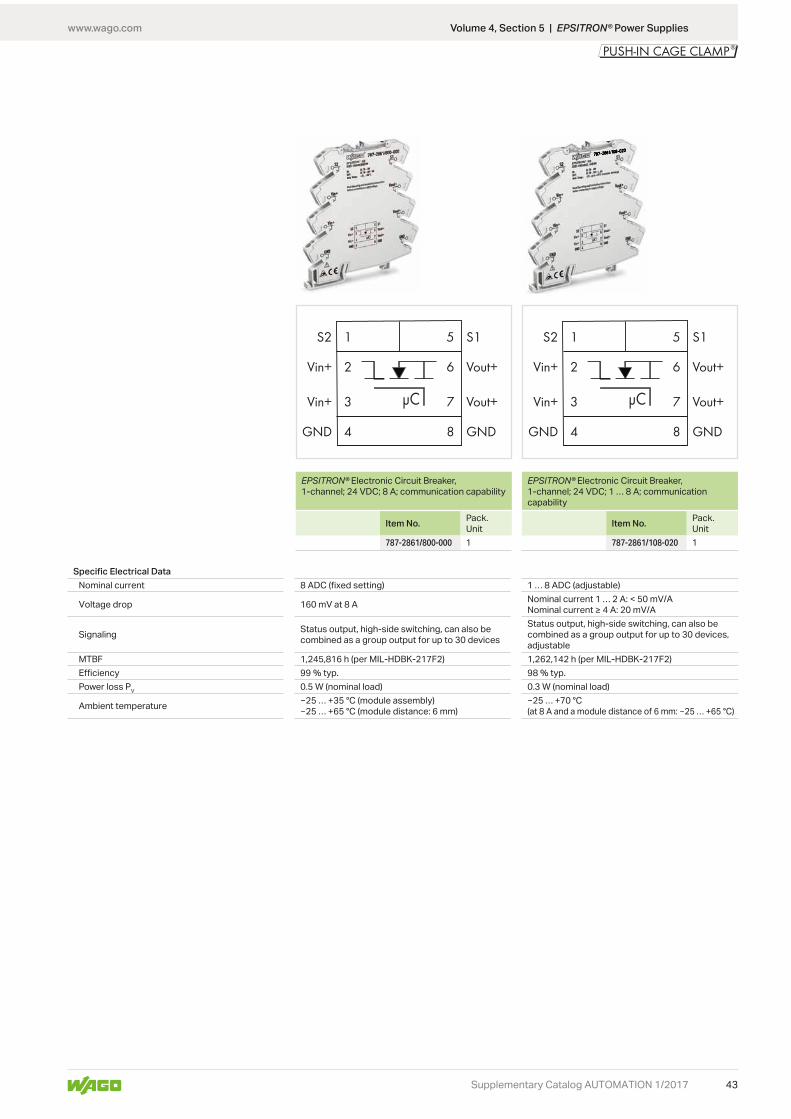
EPSITRON® Electronic Circuit Breaker, 1-channel; 24 VDC; 8 A; communication capability
Item No. Pack. Unit
787-2861/800-000 1
Volume 4, Section 5 | EPSITRON® Power Supplies
Specific Electrical DataNominal current 8 ADC (fixed setting) 1 … 8 ADC (adjustable)
Voltage drop 160 mV at 8 A Nominal current 1 … 2 A: < 50 mV/A
Signaling Status output, high-side switching, can also be combined as a group output for up to 30 devices
Status output, high-side switching, can also be combined as a group output for up to 30 devices, adjustable
MTBF 1,245,816 h (per MIL-HDBK-217F2) 1,262,142 h (per MIL-HDBK-217F2)EfficiencyPower loss PV 0.5 W (nominal load) 0.3 W (nominal load)
Ambient temperature
EPSITRON® Electronic Circuit Breaker, 1-channel; 24 VDC; 1 … 8 A; communication capability
Item No. Pack. Unit
787-2861/108-020 1
www.wago.com
44 Supplementary Catalog AUTOMATION 1/2017
Volume 4, Section 5 | EPSITRON® Power Supplies
787 Series
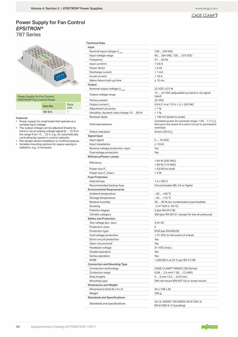
Power Supply for Fan Control EPSITRON®
Power Supply for Fan Control; EPSITRON® Fan Control Power
Item No. Pack. Unit
787-914 1
Features:• Power supply for small loads that operate at a
variable input voltage• The output voltage can be adjusted linearly by
hand or via an analog voltage signal (0 … 10 V) in the range from 12 … 22 V, e.g., for automatically controlling fan speed in control cabinets.
• Flat design allows installation in confined spaces.• Variable mounting options for space-saving in-
stallation, e.g., in recesses
Technical DataInput
Nominal input voltage Ui nom 100 ... 240 VACInput voltage range 90 … 264 VAC, 130 … 373 VDCFrequency 47 … 63 HzInput current Ii < 0.6 APower factor > 0.45Discharge current < 1 mAInrush current < 18 AMains failure hold-up time
OutputNominal output voltage Uo nom
Output voltage range 12 … 22 VDC (adjustable by hand or via signal input)
Factory preset 22 VDCOutput current Io 0.8 A (1 A at 110 V < Ui < 240 VACAdjustment accuracy
Residual ripple < 100 mV (peak-to-peak)
Overload behaviorConstant power (in overload range: 1.05 ... 1.7 x Io); Hiccup in the event of a short circuit or permanent overload
Status indication Green LED (Uo)Signal Input
Input signal 0 … 10 VDCInput impedanceReverse voltage protection, input YesOvervoltage protection Yes
Power loss PV < 0.8 W (no load)Power loss PV (max.)
Fuse ProtectionInternal fuse 1 A / 250 VRecommended backup fuse Circuit breaker B6, C4 or higher
Environmental RequirementsAmbient temperature … +60 °CStorage temperature … +75 °CRelative humidity 20 DeratingPollution degree 2 (per EN 50178)Climatic category 3K3 (per EN 60721, except for low air pressure)
Safety and ProtectionTest voltage (pri.–sec.) 3 kV ACProtection class IIProtection type IP20 (per EN 60529)Overvoltage protection < 31 VDC (in the event of a fault)Short-circuit-protection YesOpen-circuit proof YesFeedback voltage 31 VDC (max.)Parallel operation YesSeries operation YesMTBF > 500,000 h at 25 °C per IEC 61709
Connection and Mounting TypeConnection technology CAGE CLAMP® (WAGO 236 Series)Conductor range 0.08 … 2.5 mm² / 28 … 12 AWGStrip lengths 5 … 6 mm / 0.2 … 0.24 inchMounting type DIN-rail mount (EN 60715) or screw mount
Dimensions and WeightDimensions (mm) W x H x D 45 x 138 x 35Weight 300 g
1

www.wago.com
45
INL1
OUT
N
L1’
N’
Supplementary Catalog AUTOMATION 1/2017
787 Series
Radio Interference Suppression Filter, 1-PhaseEPSITRON®
10 AItem No. Pack. Unit787-980 1
Features:• Suppresses interference generated on the mains
side of power supplies and electronic devices• Fulfills general requirements• Provides a single-stage filter solution• Efficiently filters out line-bound interference
emissions• Increases the interference immunity of connect-
ed loads
Technical DataInput/Output
Nominal input voltage Ui nom 250 VACInput voltage range 0 ... 250 VACFrequency 50 … 60 HzInput current Ii 10 AOverload capacityDischarge current 8 mA
Efficiency/Power LossesPower loss Pl
Environmental RequirementsAmbient operating temperature –25 ... +70 °C, device starts at –40 °C, type-testedDeratingClimatic category 25/085/21 (per EN 60068-1)
Safety and ProtectionHousing Metal housing
Test voltage 1700 VDC (L1-N);2700 VDC (l1-PE)
Protection class IProtection type IP20 per EN 60529
Connection and Mounting Type
Connection technology L1, N: WAGO 741 SeriesGround: 6.3 x 0.8 mm tab connector
Conductor range L1, N: 0.08 … 2.5 mm² / 28 … 12 AWGGround: –
Mounting type DIN-rail mount (EN 60715)Dimensions and Weight
Dimensions (mm) W x H x D 50 x 85 x 100, depth from upper-edge of DIN-railWeight 340 g
General SpecificationsStandards/Approvals DIN EN 60939-2
Volume 4, Section 5 | EPSITRON® Power Supplies

www.wago.com
46 Supplementary Catalog AUTOMATION 1/2017
830 SeriesPotential Distribution Modules
Technical DataInput/Output
Operating voltageEnvironmental Requirements
Ambient operating temperatureRelative humidity
Connection and Mounting Type
Connection technology Input: CAGE CLAMP® (WAGO 745 Series)Output: CAGE CLAMP® (WAGO 739 Series)
General SpecificationsStandards/Approvals cULus 61010-2-201
Volume 4, Section 8 | Interface Modules with Specialty Functions
L
W
H

www.wago.com
47Supplementary Catalog AUTOMATION 1/2017
Potential distribution module, 1 potential, with 1 input clamping point, conductor cross-section up to 16 mm², with 6 output clamp-ing points, conductor cross-section up to 2.5 mm²Color Item No. Pack. Unitgray 830-800/000-302 10
blue 830-800/000-302/ 000-006
10
Potential distribution module, 1 potential, with 1 input clamping point, conductor cross-section up to 16 mm², with 9 output clamp-ing points, conductor cross-section up to 2.5 mm²Color Item No. Pack. Unitgray 830-800/000-303 10
Specific Technical DataMax. total current 65 A 65 AMax. current per connection 12 A 10 A
Conductor range Input: 0.2 … 16 mm² / 24 … 6 AWGOutput: 0.08 … 2.5 mm² / 28 … 12 AWG
Input: 0.2 … 16 mm² / 24 … 6 AWGOutput: 0.08 … 2.5 mm² / 28 … 12 AWG
Strip length Input: 11 … 12 mm / 0.43 … 0.47 inchOutput: 8 … 9 mm / 0.31 … 0.35 inch
Input: 11 … 12 mm / 0.43 … 0.47 inchOutput: 5 … 6 mm / 0.2 … 0.24 inch
Dimensions (mm) W x H x D 21 x 49 x 85, height from upper-edge of DIN-rail 21 x 62 x 85, height from upper-edge of DIN-railWeight 51 g 57
Volume 4, Section 8 | Interface Modules with Specialty Functions

www.wago.com
48
P1 P2 P2P1 P1 P2 P2P1
Supplementary Catalog AUTOMATION 1/2017
Potential distribution module, 2 potentials, with 2 input clamping points, con-ductor cross-section up to 6 mm², each with 8 output clamping points, conductor cross-section up to 2.5 mm²Color Item No. Pack. Unitgray 830-800/000-305 6
Potential distribution module, 2 potentials, with 2 input clamping points, con-ductor cross-section up to 6 mm², each with 12 output clamping points, conductor cross-section up to 2.5 mm²Color Item No. Pack. Unitgray 830-800/000-306 6
Specific Technical DataMax. total current 30 A 30 AMax. current per connection 10 A 10 A
Conductor range Input: 0.2 … 6 mm² / 24 … 10 AWGOutput: 0.08 … 2.5 mm² / 28 … 12 AWG
Input: 0.2 … 6 mm² / 24 … 10 AWGOutput: 0.08 … 2.5 mm² / 28 … 12 AWG
Strip length Input: 11 … 12 mm / 0.43 … 0.47 inchOutput: 5 … 6 mm / 0.2 … 0.24 inch
Input: 11 … 12 mm / 0.43 … 0.47 inchOutput: 5 … 6 mm / 0.2 … 0.24 inch
Dimensions (mm) W x H x D 49 x 38 x 55, height from upper-edge of DIN-rail 69 x 38 x 55, height from upper-edge of DIN-railWeight 75 g 91
Volume 4, Section 8 | Interface Modules with Specialty Functions

www.wago.com
49
P1 P2 P2P1 P1 P2 P2P1
Supplementary Catalog AUTOMATION 1/2017
Potential distribution module, 2 potentials, with 2 input clamping points, con-ductor cross-section up to 6 mm², each with 16 output clamping points, conductor cross-section up to 2.5 mm²Color Item No. Pack. Unitgray 830-800/000-307 6
Potential distribution module, 2 potentials, with 2 input clamping points, con-ductor cross-section up to 6 mm², each with 24 output clamping points, conductor cross-section up to 2.5 mm²Color Item No. Pack. Unitgray 830-800/000-308 6
Specific Technical DataMax. total current 30 A 30 AMax. current per connection 10 A 10 A
Conductor range Input: 0.2 … 6 mm² / 24 … 10 AWGOutput: 0.08 … 2.5 mm² / 28 … 12 AWG
Input: 0.2 … 6 mm² / 24 … 6 AWGOutput: 0.08 … 2.5 mm² / 28 … 12 AWG
Strip length Input: 11 … 12 mm / 0.43 … 0.47 inchOutput: 5 … 6 mm / 0.2 … 0.24 inch
Input: 11 … 12 mm / 0.43 … 0.47 inchOutput: 5 … 6 mm / 0.2 … 0.24 inch
Dimensions (mm) W x H x D 89 x 38 x 55, height from upper-edge of DIN-rail 102 x 38 x 55, height from upper-edge of DIN-railWeight 112 g 141
Volume 4, Section 8 | Interface Modules with Specialty Functions

www.wago.com
50 Supplementary Catalog AUTOMATION 1/2017
Potential distribution module, 1 potential, with 1 input clamping point, conductor cross-section up to 16 mm², with lever, with 6 output clamping points, conductor cross-section up to 2.5 mm²Color Item No. Pack. Unitgray 830-800/000-312 10
blue 830-800/000-312/ 000-006
10
Potential distribution module, 1 potential, with 1 input clamping point, conductor cross-section up to 16 mm², with lever, with 9 output clamping points, conductor cross-section up to 2.5 mm²Color Item No. Pack. Unitgray 830-800/000-313 10
Specific Technical DataMax. total current 65 A 65 AMax. current per connection 12 A 10 A
Conductor range Input: 1.5 … 16 mm² / 16 … 6 AWGOutput: 0.08 … 2.5 mm² / 28 … 12 AWG
Input: 1.5 … 16 mm² / 16 … 6 AWGOutput: 0.08 … 2.5 mm² / 28 … 12 AWG
Strip length Input: 12 … 13 mm / 0.47 … 0.51 inchOutput: 8 … 9 mm / 0.31 … 0.35 inch
Input: 12 … 13 mm / 0.47 … 0.51 inchOutput: 5 … 6 mm / 0.2 … 0.24 inch
Dimensions (mm) W x H x D 21 x 49 x 85, height from upper-edge of DIN-rail 21 x 62 x 85, height from upper-edge of DIN-railWeight 51 g 57
Volume 4, Section 8 | Interface Modules with Specialty Functions

www.wago.com
51
P1 P2 P2P1
Supplementary Catalog AUTOMATION 1/2017
Potential distribution module, 1 potential, with 2 input clamping points, conduc-tor cross-section up to 6 mm², with levers, with 9 output clamping points, conductor cross-section up to 2.5 mm²Color Item No. Pack. Unitgray 830-800/000-314 10
Potential distribution module, 2 potentials, with 2 input clamping points, con-ductor cross-section up to 6 mm², with levers, each with 8 output clamping points, conductor cross-section up to 2.5 mm²Color Item No. Pack. Unitgray 830-800/000-315 10
Specific Technical DataMax. total current 30 A 30 AMax. current per connection 10 A 10 A
Conductor range Input: 0.5 … 6 mm² / 20 … 10 AWGOutput: 0.08 … 2.5 mm² / 28 … 12 AWG
Input: 0.5 … 6 mm² / 20 … 10 AWGOutput: 0.08 … 2.5 mm² / 28 … 12 AWG
Strip length Input: 11 mm / 0.43 inchOutput: 5 … 6 mm / 0.2 … 0.24 inch
Input: 11 … 12 mm / 0.43 … 0.47 inchOutput: 5 … 6 mm / 0.2 … 0.24 inch
Dimensions (mm) W x H x D 21 x 62 x 85, height from upper-edge of DIN-rail 49 x 38 x 55, height from upper-edge of DIN-railWeight 56 g 76
Volume 4, Section 8 | Interface Modules with Specialty Functions
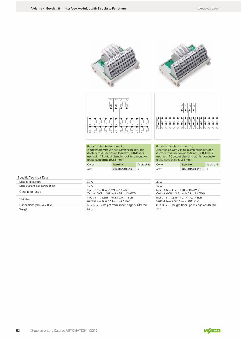
www.wago.com
52
P1 P2 P2P1P1 P2 P2P1
Supplementary Catalog AUTOMATION 1/2017
Potential distribution module, 2 potentials, with 2 input clamping points, con-ductor cross-section up to 6 mm², with levers, each with 12 output clamping points, conductor cross-section up to 2.5 mm²Color Item No. Pack. Unitgray 830-800/000-316 6
Potential distribution module, 2 potentials, with 2 input clamping points, con-ductor cross-section up to 6 mm², with levers, each with 16 output clamping points, conductor cross-section up to 2.5 mm²Color Item No. Pack. Unitgray 830-800/000-317 6
Specific Technical DataMax. total current 30 A 30 AMax. current per connection 10 A 10 A
Conductor range Input: 0.5 … 6 mm² / 20 … 10 AWGOutput: 0.08 … 2.5 mm² / 28 … 12 AWG
Input: 0.5 … 6 mm² / 20 … 10 AWGOutput: 0.08 … 2.5 mm² / 28 … 12 AWG
Strip length Input: 11 … 12 mm / 0.43 … 0.47 inchOutput: 5 … 6 mm / 0.2 … 0.24 inch
Input: 11 … 12 mm / 0.43 … 0.47 inchOutput: 5 … 6 mm / 0.2 … 0.24 inch
Dimensions (mm) W x H x D 69 x 38 x 55, height from upper-edge of DIN-rail 89 x 38 x 55, height from upper-edge of DIN-railWeight 97 g 108
Volume 4, Section 8 | Interface Modules with Specialty Functions

www.wago.com
53
P1 P2 P2P1
P1 P2 P2P1
Supplementary Catalog AUTOMATION 1/2017
Potential distribution module, 2 potentials, with 2 input clamping points, con-ductor cross-section up to 6 mm², with levers, each with 24 output clamping points, conductor cross-section up to 2.5 mm²Color Item No. Pack. Unitgray 830-800/000-318 3
Potential distribution module, 2 potentials, with 2 input clamping points, con-ductor cross-section up to 6 mm², with levers, each with 8 output clamping points, conductor cross-section up to 2.5 mm², with fuseColor Item No. Pack. Unitgray 830-800/000-319 3
Specific Technical DataMax. total current 30 A 30 AMax. current per connection 10 A 6.3 A
Conductor range Input: 0.5 … 6 mm² / 20 … 10 AWGOutput: 0.08 … 2.5 mm² / 28 … 12 AWG
Input: 0.5 … 6 mm² / 20 … 10 AWGOutput: 0.08 … 2.5 mm² / 28 … 12 AWG
Strip length Input: 11 … 12 mm / 0.43 … 0.47 inchOutput: 5 … 6 mm / 0.2 … 0.24 inch
Input: 11 … 12 mm / 0.43 … 0.47 inchOutput: 5 … 6 mm / 0.2 … 0.24 inch
Dimensions (mm) W x H x D 102 x 53 x 55, height from upper-edge of DIN-rail 98 x 48 x 106, height from upper-edge of DIN-railWeight 145 g 163
Volume 4, Section 8 | Interface Modules with Specialty Functions

www.wago.com
54 Supplementary Catalog AUTOMATION 1/2017
Micro-WSB Inline Markers
Micro-WSB Inline markers are compatible with 2857 Series Modular Empty Housings.
Micro-WSB Inline markers, plain, 2,000 markers (4 mm) per reel, not stretchablefor: Color Item No. Pack. UnitModular Empty Housing, 2857 Series
white 2009-141 1
Volume 6, Section 1 | Terminal Block Marking
www.wago.com
55Supplementary Catalog AUTOMATION 1/2017
Circuit ID labels, self-adhesive, plain, 750 labels per roll, single-rowColor Item No. Pack. Unit
white 210-813 1
Circuit ID Labels
Volume 6, Section 3 | Device Marking

www.wago.com
56
°C
Supplementary Catalog AUTOMATION 1/2017
JUMPFLEX® Signs and Symbols
Signal Conditioners and Specialty Functions General
Output Signals
Input Signals
Relay, 1 changeover contact
Current
Temperature sensors
Relay, 1 make contact
Voltage
Connection technology
Bipolar signals (current and voltage)
Supply voltage
Voltage signal conditioner
Digital output (DO)
Resistors
Bipolar signals (current and voltage)
Zero/span adjustment
Frequencies
Current
Clipping function
Potentiometer
Voltage
Temperature signal conditioner
Threshold value switch
Frequency signal conditioner
Potentiometer signal conditioner
Resistance signal conditioner
Current signal conditioner
DIP switch
software
display
Push/slide switch
Indexes and Addresses
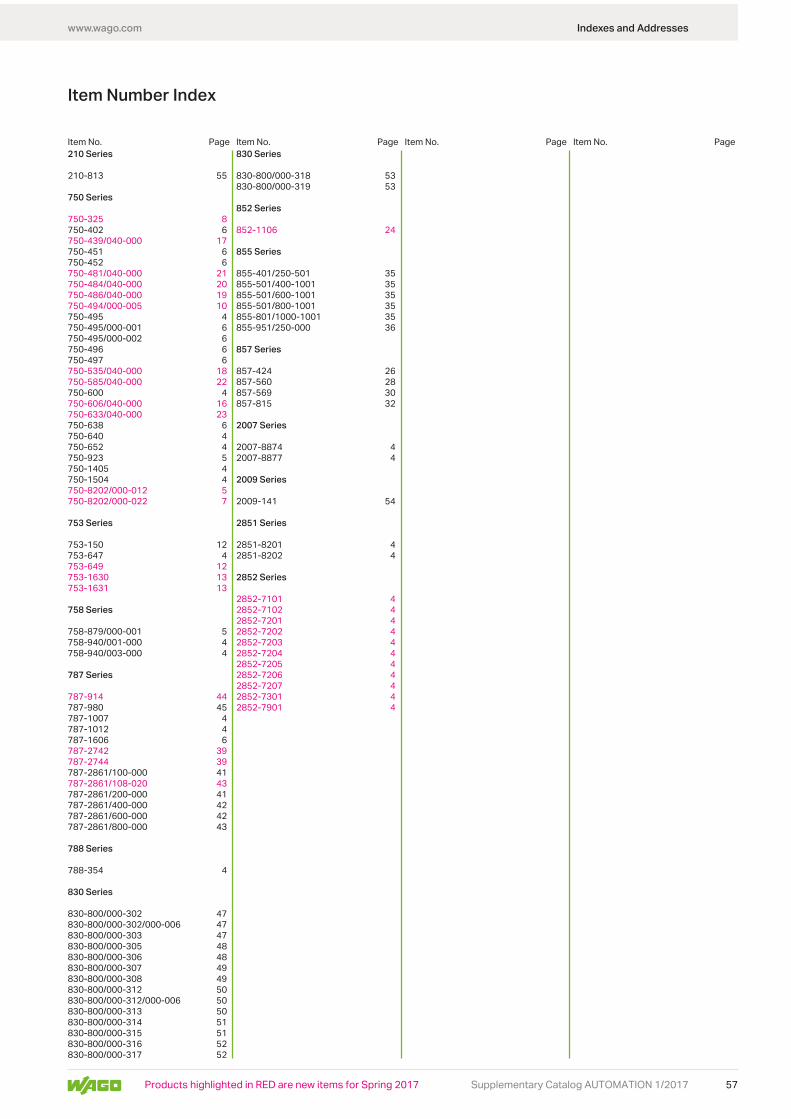
www.wago.com
57Supplementary Catalog AUTOMATION 1/2017
210 Series
210-813 55
750 Series
750-325 8750-402 6750-439/040-000 17750-451 6750-452 6750-481/040-000 21750-484/040-000 20750-486/040-000 19750-494/000-005 10750-495 4750-495/000-001 6750-495/000-002 6750-496 6750-497 6750-535/040-000 18750-585/040-000 22750-600 4750-606/040-000 16750-633/040-000 23750-638 6750-640 4750-652 4750-923 5750-1405 4750-1504 4750-8202/000-012 5750-8202/000-022 7
753 Series
753-150 12753-647 4753-649 12753-1630 13753-1631 13
758 Series
758-879/000-001 5758-940/001-000 4758-940/003-000 4
787 Series
787-914 44787-980 45787-1007 4787-1012 4787-1606 6787-2742 39787-2744 39787-2861/100-000 41787-2861/108-020 43787-2861/200-000 41787-2861/400-000 42787-2861/600-000 42787-2861/800-000 43
788 Series
788-354 4
830 Series
830-800/000-302 47830-800/000-302/000-006 47830-800/000-303 47830-800/000-305 48830-800/000-306 48830-800/000-307 49830-800/000-308 49830-800/000-312 50830-800/000-312/000-006 50830-800/000-313 50830-800/000-314 51830-800/000-315 51830-800/000-316 52830-800/000-317 52
830 Series
830-800/000-318 53830-800/000-319 53
852 Series
852-1106 24
855 Series
855-401/250-501 35855-501/400-1001 35855-501/600-1001 35855-501/800-1001 35855-801/1000-1001 35855-951/250-000 36
857 Series
857-424 26857-560 28857-569 30857-815 32
2007 Series
2007-8874 42007-8877 4
2009 Series
2009-141 54
2851 Series
2851-8201 42851-8202 4
2852 Series
2852-7101 42852-7102 42852-7201 42852-7202 42852-7203 42852-7204 42852-7205 42852-7206 42852-7207 42852-7301 42852-7901 4
Item No. Item No. Item No. Item No.Page Page Page Page
Item Number Index
Indexes and Addresses
Products highlighted in RED are new items for Spring 2017

www.wago.com
58 Supplementary Catalog AUTOMATION 1/2017
Indexes and Addresses
Algeriaplease contact WAGO France
ArgentinaBruno Schillig S.A.Arenales 4030, B1604CFDFlorida, PBAPhone +54 11 4730 1100Fax +54 11 4761 [email protected]
AustriaWAGO Kontakttechnik Ges.m.b.H.Europaring F15 602Campus 212345 Brunn am GebirgePhone +43 1 6150780Fax +43 1 [email protected]
AzerbaijanAZ Technics LTD
Y.Safarov str.33, AZ1025,Baku
Phone +994 50 210 24 49Fax +994 12 496 83 34
AustraliaWAGO Pty. Ltd.2-4 Overseas Drive
Phone +61 03 8791 6300Fax +61 03 9701 0177
Bangladeshplease contact WAGO India
BelarusOOO FEKpr-t Pushkina 29-B220015 MinskPhone +375 17 2102189Fax +375 17 [email protected]
220006 MinskPhone +375 17 2054015Fax +375 17 2851759
BelgiumWAGO BeLux nvExcelsiorlaan 111930 ZaventemPhone +32 2 717 9090Fax +32 2 717 [email protected]
BoliviaISOTEK S.R.L.
Calle Isso #578, B/San Roque
Phone +591 721 000 27
Bosnia and Herzegovinaplease contact WAGO Bulgaria
BrazilWAGO Eletroeletrônicos LtdaRua Américo Simões 1470Sãu Roque da ChaveItupeva SP Brasil 13295-000Phone +55 11 4591 0199Fax +55 11 4591 [email protected]
BulgariaWAGO Kontakttechnik GmbH & Co. KG/
Business Center Serdika2E Akad. Ivan Geshov Blvd.
Phone +359 2 489 46 09/10Fax +359 2 928 28 [email protected]
Canadaplease contact WAGO USA
ChileDesimat Chile
Pudahuel SantiagoPhone +56 2 747 0152Fax +56 2 747 [email protected]
China
No.5, Quan Hui RoadWuqing Development Area
Phone +86 22 5967 7688Fax +86 22 5961 [email protected]
ColombiaT.H.L. Ltda.Cra. 49 B # 91-33BogotáPhone +57 1 621 85 50Fax +57 1 621 60 [email protected]
CroatiaM.B.A. d.o.o.Frana Supila 5
Phone +385 51 275-736Fax +385 51 [email protected]
MICROSTAR d.o.o.Siget 18 b10020 ZagrebPhone +385 1 3647 849Fax +385 1 3636 [email protected]
Czech RepublicWAGO Elektro spol. sr. o.
Phone +420 261 090 143Fax +420 261 090 144
DenmarkWAGO Denmark A/S
Phone +45 44 357 [email protected]
EgyptIBN Engineering Instrumentation & Control71 a El Shaheed Ahmed Hamdi St.
Phone +20 2 721 4350Fax +20 2 722 [email protected]
EcuadorECUAINSETEC CIA LTDA
QuitoPhone +593 2 24 50 475Fax +593 2 22 51 [email protected]
EstoniaEltarko OÜLaki 14 - 50210621 TallinnPhone +372 651 7731Fax +372 651 [email protected]
FinlandWAGO Finland Oy
00550 HelsinkiPhone +358 9 7744 060Fax +358 9 7744 0660
FranceWAGO Contact SASParis Nord 283 Rue des ChardonneretsB.P. 55065 - Tremblay en France95947 - ROISSY CDG CEDEXPhone +33 1 4817 2590Fax +33 1 4863 [email protected]
GermanyWAGO Kontakttechnik GmbH & Co. KGPostfach 28 80, 32385 MindenHansastraße 2732423 MindenPhone +49 571 887-0Fax +49 571 [email protected]
GermanyWAGO Kontakttechnik GmbH & Co. KGWaldstraße 199706 SondershausenPhone +49 3632 659-0Fax +49 3632 [email protected]
Great BritainWAGO Limited
EstateRUGBY
Phone +44 1788 568 008Fax +44 1788 568 [email protected]
GreecePANAGIOTIS SP. DIMOULASDIMOULAS AUTOMATIONSKritis Str. 2610439 AthensPhone +30 210 883 3337Fax +30 210 883 [email protected]
Honduras
Barrio Los Andes7 Calle entre 14 y 15 Ave. N.O.P.O. Box. 1061San Pedro SulaPhone +504 2557 1146/7Fax +504 2557 1149
Hong KongNational Concord Eng., Ltd.Unit A-B, 5/F.Southeast Industrial Building611-619 Castle Peak RoadTsuen Wan, N.T.Phone +852 2429 2611Fax +852 2429 [email protected]
HungaryWAGO Hungá¡ria KFTIpari Park, Gyár u. 22040 BudapestPhone +36 23 502-170Fax +36 23 [email protected]
Iceland
Audbrekku 9-11202 KopavogurPhone +354 520-4500Fax +354 [email protected]
IndiaWAGO Private LimitedC-27, Sector-58, Phase-IIINoida-201 301
Phone +91 120 438 8700Fax +91 120 438 [email protected]
Indonesiaplease contact WAGO Singapore
Iraqplease contact WAGO Middle East
IrelandDrives & ControlsUnit F4, Riverview Business ParkNangor RoadDublin 12Phone +353 1 4604474Fax +353 1 [email protected]
IsraelComtel Israel Electronic Solutions Ltd.Bet Hapaamon20 Hataas StreetP.O. Box 6644425 Kefar-SabaPhone +972 9 76 77 240Fax +972 9 76 77 [email protected]
ItalyWAGO ELETTRONICA SRL a Socio Unico
Phone +39 051 6132112Fax +39 051 [email protected]
JapanWAGO Co. of JAPAN Ltd.Kinshicho Prime Tower5-7, Kameido, Koto-KuTokyo 136-0071Phone +81 3 5627 2059Fax +81 3 5627 2055
Jordanplease contact WAGO Middle East
KazakhstanTOO INTANT232/2, Ryskulov avenue050061 AlmatyPhone +7 727 356 52 91/92/93Fax +7 727 327 14 92/[email protected][email protected]
TOO Technik-Tradeul. i. A. Protosanova, 81070004 Ust-KamenogorskPhone +7 7232 254 064Fax +7 7232 253 251
KoreaWAGO Korea Co., Ltd.
268, Hagui-ro, Dongan-gu, Anyang-si, Gyeonggi-do, 14056, South KoreaPhone +82 31 421 [email protected]
Kosovoplease contact WAGO Bulgaria
Latvia
Phone +371 6790 1188Fax +371 6790 [email protected]
LebanonGemayel Trading & Contracting
P.O. BOX 70-1096AnteliasLebanonPhone +961 4 521 029Fax +961 4 521 [email protected]
LithuaniaINSTABALT LIT UAB
Phone +370 52 322 295Fax +370 52 322 [email protected]
Luxembourgplease contact WAGO Belgium
Macedoniaplease contact WAGO Bulgaria
Republic of MacedoniaPhone +389 2 521 12 00Phone +389 2 246 11 08
Malaysia
No 806, Block A4, Leisure Commerce Square,No 9, Jalan PJS 8/9, 46150 Petaling Jaya,Selangor Darul Ehsan, MalaysiaPhone +60 3 7877 1776Fax +60 3 7877 [email protected]
No. 4, Jalan Nilam 1/6Suban Hi-Tech Industrial Park40000 Shah AlamSelangor, D.E. MalaysiaPhone +60 3 5638 2213Fax +60 3 5638 [email protected]
Maledivesplease contact WAGO India
WAGO WorldwideCompanies and Representatives

www.wago.com
59Supplementary Catalog AUTOMATION 1/2017
Indexes and Addresses
Mexico
Av. Del Marques 38 Bodega 3P. I. Bernardo Quintana76246 El Marques, QuerétaroPhone +52 442 221 5946Fax +52 442 221 [email protected]
MoldovaElectroservice Slavinschi T.T.
2001 KishinevPhone +373 22 274427Fax +373 22 [email protected]
MoroccoAutomatisme & Connection Maroc23, Rue Boured, 2ème étage, appt4Roche Noire20300 CasablancaPhone +212 522 24 21 72/73Fax +212 522 24 21 [email protected]
Nepalplease contact WAGO India
Netherlands
Laan van de Ram 197234 BW APELDOORNPhone +31 55 36 83 500Fax +31 55 36 83 [email protected]
New Zealandplease contact WAGO Australia
NHP NZ7 Lockhart PlaceMt WellingtonNew ZealandPhone +64 9 2761967Fax +64 9 [email protected]
NigeriaGIL Automations Ltd.Daily Times Complex2 Lateef Jakande Rd., Agidingbi
Phone +234 [email protected]
NorwayWAGO Norge ASJerikoveien 201067 OsloPhone +47 22 30 94 50Fax +47 22 30 94 [email protected]
Omanplease contact WAGO Middle East
Pakistan
Suit No. 14, 5th Floor, Shan ArcadeNew Garden Town, LahorePakistanPhone +92 42 594 1503 - 4Fax +92 42 585 1431
ParaguayAESAAv. Madame Lynchc/Antolin Irala2309 Asunción
PeruManufacturas Eléctricas S.A.Av O.R. Benavides 121515000 LimaPhone +511 6196200Fax +511 6196247
Philippinesplease contact WAGO Singapore
Poland
Phone +48 71 3602970Fax +48 71 [email protected]
PortugalMORGADO & CA. LDA - SEDEEstrada Exterior daCircunvalação 3558/3560Apartado 10574435 Rio TintoPhone +351 22 9770600Fax +351 22 [email protected]
Quatarplease contact WAGO Middle East
RomaniaWAGO Kontakttechnik GmbH & Co. KG
Sos. Pipera-Tunari nr. 1/1
RomaniaPhone +40 21 3225074/76Fax +40 21 3225075
Russia
Dmitrovskoe shosse, 157, bldg. 12/5 127411 MoscowRussiaPhone +7 495 663-3305Fax +7 495 [email protected]
OOO Decima
124460 Moscow / SelenogradPhone +7 495 988 4858Fax +7 495 988 [email protected] OOO Prosoft
117437 MoscowPhone +7 495 2340636Fax +7 495 [email protected]
ITC Electronics: MoscowRadio str. 24105005 MoscowPhone +7 495 775 1845Fax +7 495 775 [email protected]
EkaterinburgPhone +7 343 216 3426
NovosibirskPhone +7 383 217 9244
St. PetersburgPhone +7 812 312 1918
Saudi ArabiaSaudi Electronic Trading Company
11555-RiyadhPhone +966 1 2062277Fax +966 1 [email protected]
Serbiaplease contact WAGO Bulgaria
Avalon Partners doo
11000 BeogradPhone +381 11 268 5311Fax +381 11 268 5311
Sigma doo
21000 Novi SadPhone +381 21 468 431Fax +381 21 636 1785
SingaporeWAGO Electronic Pte Ltd
Singapore 367904Phone +65 62866776Fax +65 [email protected]
SlovakiaProelektro spol. s r.o.Na barine 22
Phone +421 2 4569 2503 [email protected]
SloveniaIC elektronika d.o.o.
Phone +386 1568 0126Fax +386 1568 [email protected]
GENERA d.o.o.Prevale 10
Phone +386 14393050Fax +386 [email protected]
SloveniaElektronabava d.o.o.
Phone +386 1 58 99 300Fax +386 1 58 99 [email protected]
South Africa
Postnet Suite # 219Private Bag X 8,Elardus Park0047 PRETORIAPhone +27 12 4500300Fax +27 12 4500322
SpainDICOMAT S.L.Avda. de la Industria, 36Apartado Correos, 1.178
Phone +34 91 662 1362Fax +34 91 661 [email protected]
SwedenWAGO Sverige ABTyskland FilialBox 11127, 161 11 BROMMABesöksadress: Adolfsbergsv. 31Phone +46 858410680Fax +46 [email protected]
SwitzerlandWAGO CONTACT SARte. de l’Industrie 19Case Postale 1681564 DomdidierPhone +41/26 676 75 00Fax +41/26 676 75 01
Sri Lankaplease contact WAGO India
SyriaZahabi Co.8/5 Shouhadaa St., P.O. Box 8262AleppoPhone +963 21 21 22 235 / 6Fax +963 21 21 22 23 [email protected]
Taiwan R.O.C.WAGO Contact, Ltd.5F., No.168, Jiankang RdZhonghe CityTaipei County 23585, TaiwanPhone +886 2 2225 0123Fax +886 2 2225 [email protected]
Thailand
4th Floor, KS Building213/6-8 Rachada-Phisek RoadDingdaeng, Bangkok 10400Phone +66 2 6935611Fax +66 2 [email protected]
US Power Distribution Co., Ltd.4th Floor, KS Building213/6-8 Rachada-Phisek RoadDingdaeng, Bangkok 10400Phone +66 2 2763040Fax +66 2 [email protected]
ThailandItthirit Technology Co., Ltd.
Soi Raminthra 55/8, Watcharapon RoadTharaeng, Bangkhen DistrictBangkok Thailand 10220
Fax +66 2 347 [email protected]
Tunisiaplease contact WAGO France
TurkeyWAGO Elektronik Sanayi ve Ticaret
Yukan Dudullu Mahallesi Bayraktar
Cad. Hattat Sok. No. 1034775 Ümraniye - IstanbulPhone +90 216 472 1133Fax +90 216 472 [email protected]
UkraineNPP Logicon
03150 KievPhone +380 44 5228019Fax +380 44 [email protected]
OOO Micropriborul. Kotelnikova, 403115 KievPhone +380 44 5369386Fax +380 44 [email protected]
United Arab Emirates (UAE)
SAIF Zone, Q4-282P.O. Box 120665
Phone +971 6 5579920Fax +971 6 [email protected]
UruguayFivisa ElectricidadAvda. Urugay 127411100 MontevideoPhone +59 829 020 808Fax +59 829 021 230
USAWAGO CORPORATIONN120 W19129 Freistadt RoadGermantown, WI 53022Phone +1 262 255 6222Fax +1 262 255 3232
VenezuelaPETROBORNAS, C.A.C.C. PLAZA AEROPUERTO - PISO 1 - LOCAL P1-B-03
Phone +58 286 951 3382Fax +58 286 951 [email protected]
Vietnamplease contact WAGO Germany
Current addresses at www.wago.com

www.wago.com
60 Supplementary Catalog AUTOMATION 1/2017
Notes

is a registered trademark of WAGO Verwaltungsgesellschaft mbH.

0888
-100
2/01
17-6
901
- Sup
pl. C
at. A
utom
atio
n Te
chno
logy
and
Inte
rfac
e El
ectr
onic
201
7/1
US -
04/2
017-
00 -
Prin
ted
in G
erm
any
- Sub
ject
to d
esig
n ch
ange
s
WAGO Kontakttechnik GmbH & Co. KGPostfach 2880 · D · 32385 MindenHansastraße 27 · D · 32423 [email protected]


