Automation of Bottle Manufacturing, Filling and … · Automation of Bottle Manufacturing, Filling...
9
Automation of Bottle Manufacturing, Filling and Capping Process using Low Cost Industrial Automation Avunoori Anudeep Kumar 1 1 Student (M.Tech Mechatronics) Dept. of Mechanical Engineering Mahatma Gandhi Institute of Technology Hyderabad, Telangana, India. Pundru Srinivasa Rao 2 2 Associate Professor Dept. of Mechanical Engineering Mahatma Gandhi Institute of Technology Hyderabad, Telangana, India. Abstract: The small scale industries go for manual operations to manufacture bottles, filling and capping them. These industries requires large amount of labour for operating the machines, and to increase the production rate. The designed low cost industrial automation process is best suitable for small scale industries to increase the production rate of manufacturing the bottles, filling the liquid and capping the bottles. The above process have been studied and designed a better low cost industrial automation process, which is performed by pneumatic actuators with electrical control and PLC’s. The electric circuit have been designed such that, the sequence of operations are tested by using Fluidsim Pneumatic simulation software, and also the required ladder program is designed in the programmable logic controller. This leads precisely controlled actions of its operations, which permits the safe control of its operating process. The designed automation process is of programmable. The sequence of operations are such as automatic clamping, unclamping, injecting the molten material, filling and capping process of the bottles is determined. This is achieved through the use of simple devices like limit switches, relays, sensors, pneumatic actuators and electrical controls. Keywords— Fluidsim Pneumatic simulation software, PLC, Pneumatic actuators, relays I. INTRODUCTION The small scale industries use conventional methods for manufacturing the bottles, filling and capping the bottles. These bottles are filled manually and in unhygienic conditions which contaminates the products filled. Large amount of labour are required to perform these operations. The conventional process is converted into automaton process, by this method the production rate increases at a low investment. This is achieved through low cost industrial automation [10]. Automation is defined as a control system and technologies which reduces the human work in the production field [1]. Automation control system is that system which controls the process automatically and reduces the human mentor. Automation system has ability to initiate, adjust the process automatically and stop the process when desired output is obtained [5]. Low Cost Automation or Cost Effective Automation promotes cost oriented reference architectures and development approaches that properly integrate human skill. This can be achieved by introducing very simple devices such as limit switches, electrical relays, solenoid valves, pneumatic actuators [6, 7]. Use of simple devices utilizing relatively cheap and readily available components, to minimize or eliminate human effort in certain operations is called Low Cost Automation. The often-told reason not to go in for automation is the high costs involved compared to the investment in manpower. However this is only one of the aspects which most of the plant engineers look into while deciding their automation requirements. The main aim of Low Cost Industrial Automation is to increase Productivity and quality of products and reduce the cost of production. II. FLUIDSIM PNEUMATIC SIMULATION SOFTWARE AND PLC PROGRAMMING Fluidsim Pneumatics is a teaching tool for simulating pneumatics basics and runs using Microsoft Windows. It can be used in the combination with the Festo Didactic training hardware or independently. Fluidsim was developed as a joint venture between the University of Padeborn, Festo Didactic Company and Art Systems software in Padeborn. A major feature of Fluidsim is its close connection with CAD functionality and simulation. Fluidsim allows DIN-compliant drawing of electro pneumatic circuit diagrams and can perform realistic simulations. Simply stated, this eliminates the gap between drawing of a circuit diagram and the simulation of the related pneumatic system. The CAD functionality of Fluidsim has been specially tailored for fluidics. Fluidsim Pneumatic simulation software is used to design the pneumatic circuits and simulate the circuits. The electrical circuits for the automation process are designed and simulated. PLC is a device which is designed to perform the logic functions. PLC stands for programmable logic controller. RICHARD E. MORLEY invented the first PLC in 1969. The PLC programming procedure replaced a wiring of the relays, timers etc. The PLC programming is International Journal of Engineering Research & Technology (IJERT) ISSN: 2278-0181 www.ijert.org IJERTV3IS120893 Vol. 3 Issue 12, December-2014 949
Transcript of Automation of Bottle Manufacturing, Filling and … · Automation of Bottle Manufacturing, Filling...
Automation of Bottle Manufacturing, Filling and Capping Process using Low Cost Industrial
Automation
Avunoori Anudeep Kumar1
1Student (M.Tech Mechatronics)
Dept. of Mechanical Engineering
Mahatma Gandhi Institute of Technology
Hyderabad, Telangana,
India.
Pundru Srinivasa Rao2
2Associate Professor
Dept. of Mechanical Engineering
Mahatma Gandhi Institute of Technology
Hyderabad, Telangana,
India.
Abstract: The small scale industries go for manual operations
to manufacture bottles, filling and capping them. These
industries requires large amount of labour for operating the
machines, and to increase the production rate. The designed
low cost industrial automation process is best suitable for
small scale industries to increase the production rate of
manufacturing the bottles, filling the liquid and capping the
bottles. The above process have been studied and designed a
better low cost industrial automation process, which is
performed by pneumatic actuators with electrical control and
PLC’s. The electric circuit have been designed such that, the
sequence of operations are tested by using Fluidsim
Pneumatic simulation software, and also the required ladder
program is designed in the programmable logic controller.
This leads precisely controlled actions of its operations, which
permits the safe control of its operating process. The designed
automation process is of programmable. The sequence of
operations are such as automatic clamping, unclamping,
injecting the molten material, filling and capping process of
the bottles is determined. This is achieved through the use of
simple devices like limit switches, relays, sensors, pneumatic
actuators and electrical controls.
Keywords— Fluidsim Pneumatic simulation software, PLC,
Pneumatic actuators, relays
I. INTRODUCTION
The small scale industries use conventional
methods for manufacturing the bottles, filling and capping
the bottles. These bottles are filled manually and in
unhygienic conditions which contaminates the products
filled. Large amount of labour are required to perform these
operations. The conventional process is converted into
automaton process, by this method the
production rate
increases at a low investment.
This is achieved through
low
cost industrial automation [10].
Automation is defined as a control system and
technologies which reduces the human work in the
production field
[1].
Automation control system is that
system which controls
the process automatically and
reduces the human mentor. Automation system has ability
to initiate, adjust the process automatically and stop the
process when desired output is obtained [5].
Low Cost Automation or Cost Effective
Automation promotes cost oriented reference architectures
and development approaches that properly integrate human
skill. This can be achieved by introducing very simple
devices such as limit switches, electrical relays, solenoid
valves, pneumatic actuators [6, 7]. Use of simple devices
utilizing relatively cheap and readily available components,
to minimize or eliminate human effort in certain operations
is called Low Cost Automation. The often-told reason not
to go in for automation is the high costs involved compared
to the investment in manpower. However this is only one
of the aspects which most of the plant engineers look into
while deciding their automation requirements. The main
aim of Low Cost Industrial Automation is to increase
Productivity and quality of products and reduce the cost of
production.
II. FLUIDSIM PNEUMATIC SIMULATION
SOFTWARE AND PLC PROGRAMMING
Fluidsim Pneumatics is a teaching tool for
simulating pneumatics basics and runs using Microsoft
Windows. It can be used in the combination with the Festo
Didactic training hardware or independently. Fluidsim was
developed as a joint venture between the University of
Padeborn, Festo Didactic Company and Art Systems
software in Padeborn.
A major feature of Fluidsim is its close connection
with CAD functionality and simulation. Fluidsim allows
DIN-compliant drawing of electro pneumatic circuit
diagrams and can perform realistic simulations. Simply
stated, this eliminates the gap between drawing of a circuit
diagram and the simulation of the related pneumatic
system. The CAD functionality of Fluidsim has been
specially tailored for fluidics.
Fluidsim Pneumatic simulation software is used to
design the pneumatic circuits and simulate the circuits. The
electrical circuits for the automation process are designed
and simulated.
PLC is a device which is designed to perform the
logic functions. PLC stands for programmable logic
controller. RICHARD E. MORLEY invented the first PLC
in 1969. The PLC programming procedure replaced a
wiring of the relays, timers etc. The PLC programming is
International Journal of Engineering Research & Technology (IJERT)
ISSN: 2278-0181
IJERT
IJERT
www.ijert.orgIJERTV3IS120893
( This work is licensed under a Creative Commons Attribution 4.0 International License.)
Vol. 3 Issue 12, December-2014
949

written in high level language, which is easier for
understandable of the more people [11]. Any machine can
be controlled automatically by use of PLC. For automation
of process write the program in the software then transfer
the program to the PLC and after that connect the PLC to
the machine [2]. A single PLC can run many machines at
same time. The PLC has capability for handling several
inputs and outputs signal. Allen Bradley PLC and Rslogix
500 plc programming software are used for automation of
the process.
III. DESIGN SEQUENCE FOR AUTOMATION
PROCESS OF BOTTLE MANUFACTURING, FILLING
AND CAPPING THE BOTTLES
Initially when the power is on the system starts
working the process. The cylinder A. activates and clamps
the die block. Then piston of the cylinder B moves forward
and injects the molten material in to die block and the
piston goes back. Now the piston of cylinder A unclamps
the die block and the bottle ejected on to the conveyor.
Now the bottles goes to the filling section and the
sensor 1 detects the bottle and activates the cylinder C now
the piston moves forward clamps the bottle and activates
the cylinder D and the piston pushes the filler in to the
bottle and then the cylinder v activates to open the nozzle
and fills the required quantity. When the height of the
liquid is sensed by the sensor 2 then cylinder v closes the
nozzle, the piston of the cylinder D goes back and filler is
moved up and the bottle gets unclamped and moves
towards capping section.
Now the bottle goes to the capping section when
the sensor 3 detects the bottle it activates the cylinder E and
the piston moves forward and clamps the bottle. Now the
cylinder F activated and the piston comes down and fixes
the cap, the sensor 4 senses whether capping is done and
then activates the piston of the cylinder F to retract, the
cylinder E retracts and unclamps the bottle. The man at the
last of the section collects the bottle from the conveyor
belt.
The above sequence of operations with inputs and
outputs of the PLC are shown in the below fig.1
Fig 1: Inputs and Outputs connected to the PLC.
IV. SEQUENCE FOR AUTOMATION PROCESS OF
MANUFACTURING, FILLING AND CAPPING OF
BOTTLES
For automation of bottle manufacturing filling and
capping process the sequence consists of Clamping the die
block, moving the ram of injection moulding machine
downwards, wait for a while and unclamp the die block,
clamp the bottle, move the filler into the bottle, open the
nozzle valve, after filling, close the nozzle, unclamp the
bottle, clamp the bottle, move the capping motor
downwards, after capping, move the capping motor
upwards and unclamp the bottle. Thus consists of mainly
three sections bottle manufacturing, filling and capping of
the bottles.
That’s the required sequence for overall process is
A+B+B-A-C+D+V+V-D-C-E+F+F-E-. The interlocks
occurs between B+ and B-, similarly in V+ and V-, F+ and
F- to remove these interlocks relays are used. The total
sequence is divided in to three operations. They are
automation for manufacturing of the bottles by Injection
moulding machine, automation of filling the bottle,
automation of capping the bottles.
V. SEQUENCE FOR AUTOMATION OF BOTTLE
MANUFACTURING PROCESS
For automation of the bottle manufacturing
process the sequence consists clamping of the die block,
move the ram downwards and inject the molten material in
to die block, move the ram upwards, wait for a while and
unclamp the die the bottle is ejected on to the conveyor.
For automation of this process the sequence is
A+B+B-A-.
VI. DESIGN OF PNEUMATIC CIRCUIT FOR
AUTOMATION OF BOTTLE MANUFACTURING
PROCESS
a) Connect the working ports of one directional control
valve to cylinder A and the working ports of other
directional control valve to the cylinder B
b) The input port of each directional valve which is
responsible for the motion of the piston is connected to
the compressor.
c) The port of the directional valve which is responsible
of moving out the pressure from the other side of the
piston is connected to the exhaust.
d) The compressor is connected to the pressure source.
The circuit is shown in below fig 2.
Fig 2: Design of Pneumatic circuit for automation of bottle manufacturing
process
International Journal of Engineering Research & Technology (IJERT)
ISSN: 2278-0181
IJERT
IJERT
www.ijert.orgIJERTV3IS120893
( This work is licensed under a Creative Commons Attribution 4.0 International License.)
Vol. 3 Issue 12, December-2014
950

VII. DESIGN OF ELECTRIC CIRCUIT FOR
AUTOMATION OF BOTTLE MANUFACTURING
PROCESS
a) Connect the start button and solenoid valves A+,
B+ to the NC (Normally Closed) of the relay K.
b) Connect the solenoid valves B-, to the NO
(Normally Opened) of relay K.
c) Connect TB- NO with timer T as shown in circuit.
d) Connect the timer switch to the solenoid valve A-.
e) Connect the TB+ to relay K.
f) Hold the relay K with K and TA- NC.
g) The circuit is designed as per the circuit shown in
fig 3 below.
. Fig 3: Design of Electric circuit for automation of Bottle manufacturing
process.
VIII. SEQUENCE FOR AUTOMATION OF FILLING
THE BOTTLES
For automation of the filling process the sequence
consists of clamp the bottle, inject the filler in to the bottle,
open the valve, fill the bottle up to required quantity, close
the nozzle valve, eject the filler from the bottle, and
unclamp the bottle. The sequence for this process is
C+D+V+V-D-C-
Cylinders C, D, V are used for clamping of the
bottle, movement of the filler, and nozzle valve open or
close respectively.
IX. DESIGN OF PNEUMATIC CIRCUIT FOR
AUTOMATION PROCESS OF FILLING THE BOTTLES
a) Working ports of each cylinder C, D, V are connected
to working ports of each directional control valve.
b) The input port of each directional valve which is
responsible for the motion of the piston is connected to
the compressor.
c) The port of the directional valve which is responsible
of moving out the pressure from the other side of the
piston is connected to the exhaust.
d) The compressor is connected to the pressure source, as
shown in fig 4.
Fig 4: Pneumatic circuit design for automation process of filling the
Bottles.
X. Design of Electric Circuit for Automation Process of
Filling the Bottles
a) The sensors have three terminals one is connected to
+ve, -ve and the other is output.
b) The output of sensor 1 is connected to the relay K2 and
the output of the sensor s2 is connected to relay K3.
c) The relay K2 is hold with K2 NO and TV+ NC.
d) The relay K3 is hold with K3 NO and TC- NC
e) The solenoid C+ is connected to K2
f) TC+ NO and the solenoid D+ are connected to K2
g) TD+ NO and solenoid V+ are connected to K2.
h) The solenoid V- is connected to K3.
i) TV- NO and the solenoid D- are connected to K3.
j) TD- and the solenoid C- are connected to K3, as
shown in below fig 5.
Fig 5: Design of Electric circuit for automation process of filling the
bottles.
XI. SEQUENCE FOR AUTOMATION OF CAPPING
THE BOTTLES
For automation of capping process the designed
sequence is clamp the bottle, movement of the capping
motor, unclamp the bottle. For automation of this process
the designed sequence is E+F+F-E-
Two double acting pneumatic cylinders E and F
are used for clamp the bottle and to the capping motor
respectively.
International Journal of Engineering Research & Technology (IJERT)
ISSN: 2278-0181
IJERT
IJERT
www.ijert.orgIJERTV3IS120893
( This work is licensed under a Creative Commons Attribution 4.0 International License.)
Vol. 3 Issue 12, December-2014
951
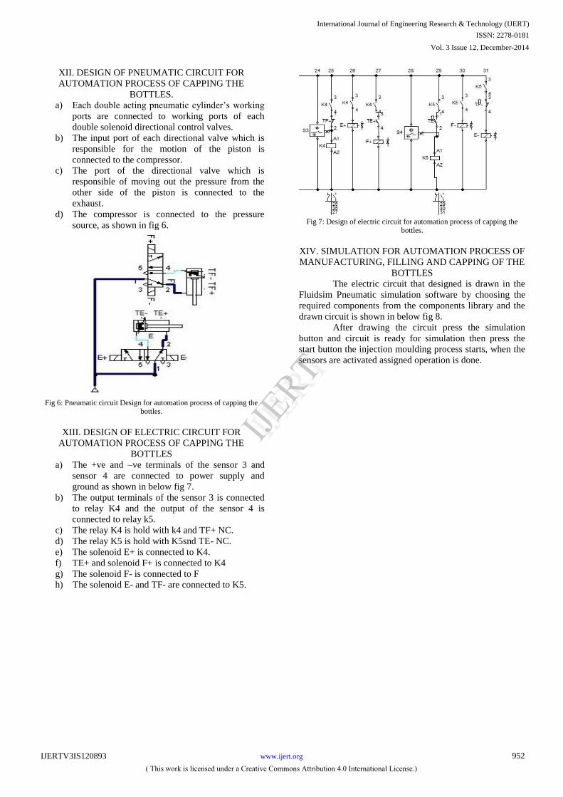
XII. DESIGN OF PNEUMATIC CIRCUIT FOR
AUTOMATION PROCESS OF CAPPING THE
BOTTLES.
a) Each double acting pneumatic cylinder’s working
ports are connected to working ports of each
double solenoid directional control valves.
b) The input port of each directional valve which is
responsible for the motion of the piston is
connected to the compressor.
c) The port of the directional valve which is
responsible of moving out the pressure from the
other side of the piston is connected to the
exhaust.
d) The compressor is connected to the pressure
source, as shown in fig 6.
Fig 6: Pneumatic circuit Design for automation process of capping the
bottles.
XIII. DESIGN OF ELECTRIC CIRCUIT FOR
AUTOMATION PROCESS OF CAPPING THE
BOTTLES
a) The +ve and –ve terminals of the sensor 3 and
sensor 4 are connected to power supply and
ground as shown in below fig 7.
b) The output terminals of the sensor 3 is connected
to relay K4 and the output of the sensor 4 is
connected to relay k5.
c) The relay K4 is hold with k4 and TF+ NC.
d) The relay K5 is hold with K5snd TE- NC.
e) The solenoid E+ is connected to K4.
f) TE+ and solenoid F+ is connected to K4
g) The solenoid F- is connected to F
h) The solenoid E- and TF- are connected to K5.
Fig 7: Design of electric circuit for automation process of capping the
bottles.
XIV. SIMULATION FOR AUTOMATION PROCESS OF
MANUFACTURING, FILLING AND CAPPING OF THE
BOTTLES
The electric circuit that designed is drawn in the
Fluidsim Pneumatic simulation software by choosing the
required components from the components library and the
drawn circuit is shown in below fig 8.
After drawing the circuit press the simulation
button and circuit is ready for simulation then press the
start button the injection moulding process starts, when the
sensors are activated assigned operation is done.
International Journal of Engineering Research & Technology (IJERT)
ISSN: 2278-0181
IJERT
IJERT
www.ijert.orgIJERTV3IS120893
( This work is licensed under a Creative Commons Attribution 4.0 International License.)
Vol. 3 Issue 12, December-2014
952
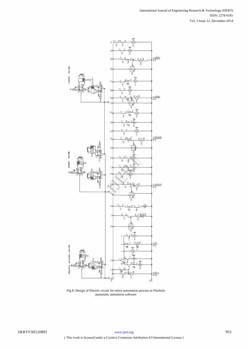
Fig
8:
Design of Electric circuit for entire automation process in Fluidsim
pneumatic simulation software
International Journal of Engineering Research & Technology (IJERT)
ISSN: 2278-0181
IJERT
IJERT
www.ijert.orgIJERTV3IS120893
( This work is licensed under a Creative Commons Attribution 4.0 International License.)
Vol. 3 Issue 12, December-2014
953
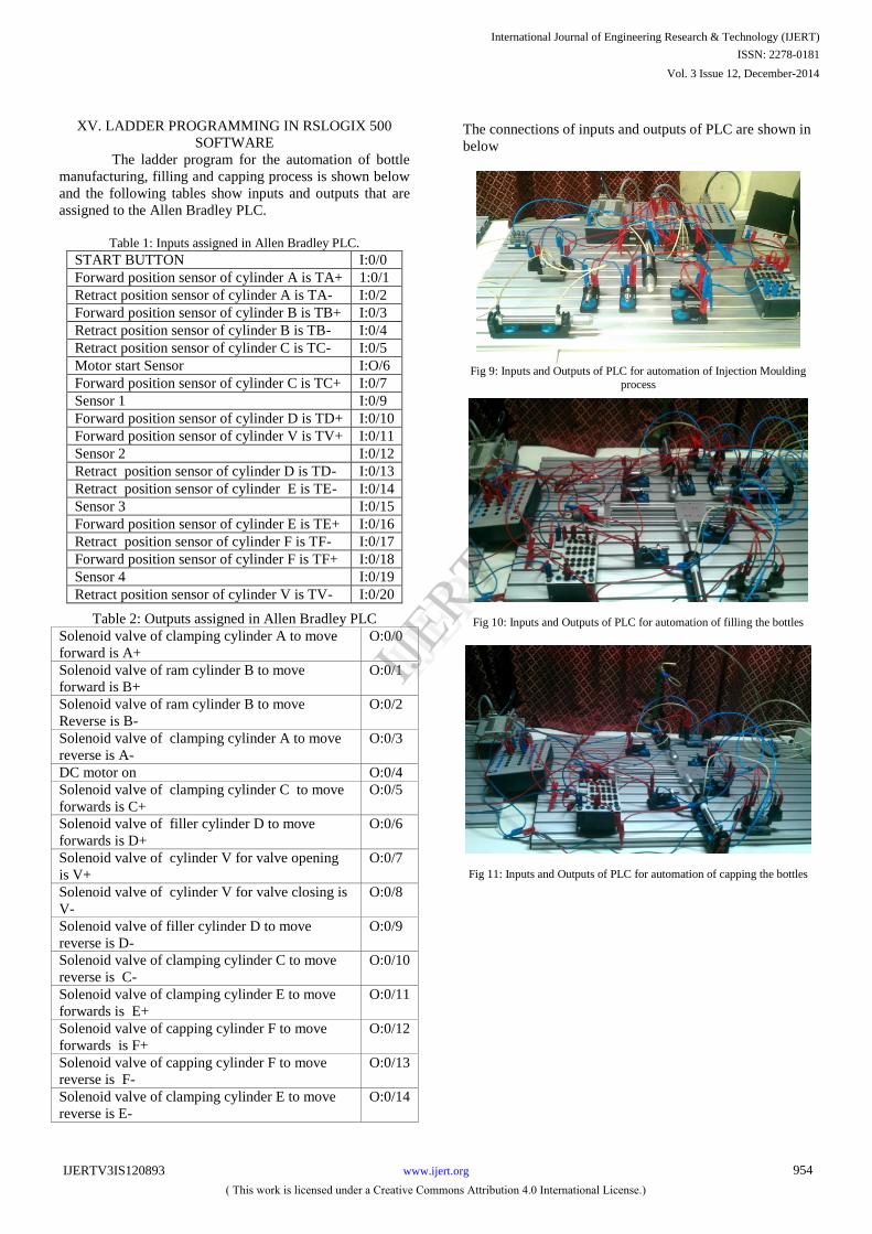
XV. LADDER PROGRAMMING IN RSLOGIX 500
SOFTWARE
The ladder program for the automation of bottle
manufacturing, filling and capping process is shown below
and the following tables show inputs and outputs that are
assigned to the Allen Bradley PLC.
Table 1: Inputs assigned in Allen Bradley PLC.
START BUTTON I:0/0
Forward position sensor of cylinder A is TA+ 1:0/1
Retract position sensor of cylinder A is TA- I:0/2
Forward position sensor of cylinder B is TB+ I:0/3
Retract position sensor of cylinder B is TB- I:0/4
Retract position sensor of cylinder C is TC- I:0/5
Motor start Sensor I:O/6
Forward position sensor of cylinder C is TC+ I:0/7
Sensor 1 I:0/9
Forward position sensor of cylinder D is TD+ I:0/10
Forward position sensor of cylinder V is TV+ I:0/11
Sensor 2 I:0/12
Retract position sensor of cylinder D is TD- I:0/13
Retract position sensor of cylinder E is TE- I:0/14
Sensor 3 I:0/15
Forward position sensor of cylinder E is TE+ I:0/16
Retract position sensor of cylinder F is TF- I:0/17
Forward position sensor of cylinder F is TF+ I:0/18
Sensor 4 I:0/19
Retract position sensor of cylinder V is TV- I:0/20
Table 2: Outputs assigned in Allen Bradley PLC
Solenoid valve of clamping cylinder A to move
forward is A+
O:0/0
Solenoid valve of ram cylinder B to move
forward is B+
O:0/1
Solenoid valve of ram cylinder B to move
Reverse is B-
O:0/2
Solenoid valve of clamping cylinder A to move
reverse is A-
O:0/3
DC motor on O:0/4
Solenoid valve of clamping cylinder C to move
forwards is C+
O:0/5
Solenoid valve of filler cylinder D to move
forwards is D+
O:0/6
Solenoid valve of cylinder V for valve opening
is V+
O:0/7
Solenoid valve of cylinder V for valve closing is
V-
O:0/8
Solenoid valve of filler cylinder D to move
reverse is D-
O:0/9
Solenoid valve of clamping cylinder C to move
reverse is C-
O:0/10
Solenoid valve of clamping cylinder E to move
forwards is E+
O:0/11
Solenoid valve of capping cylinder F to move
forwards is F+
O:0/12
Solenoid valve of capping cylinder F to move
reverse is F-
O:0/13
Solenoid valve of clamping cylinder E to move
reverse is E-
O:0/14
The connections of inputs and outputs of PLC are shown in
below
Fig 9: Inputs and Outputs of PLC for automation of Injection Moulding
process
Fig 10: Inputs and Outputs of PLC for automation of filling the bottles
Fig 11: Inputs and Outputs of PLC for automation of capping the bottles
International Journal of Engineering Research & Technology (IJERT)
ISSN: 2278-0181
IJERT
IJERT
www.ijert.orgIJERTV3IS120893
( This work is licensed under a Creative Commons Attribution 4.0 International License.)
Vol. 3 Issue 12, December-2014
954
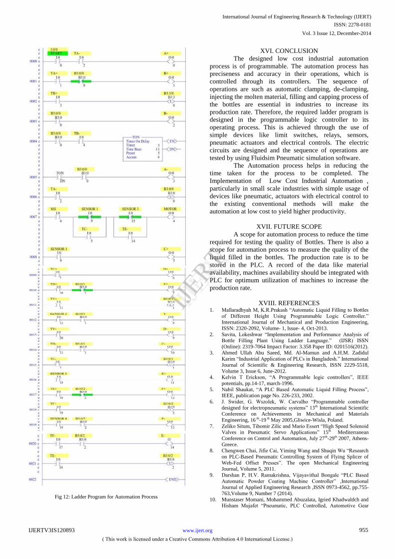
Fig 12: Ladder Program for Automation Process
XVI. CONCLUSION
The designed low cost industrial automation
process is of programmable. The automation process has
preciseness and accuracy in their operations, which is
controlled through its controllers. The sequence of
operations are such as automatic clamping, de-clamping,
injecting the molten material, filling and capping process of
the bottles are essential in industries to increase its
production rate. Therefore, the required ladder program is
designed in the programmable logic controller to its
operating process. This is achieved through the use of
simple devices like limit switches, relays, sensors,
pneumatic actuators and electrical controls. The electric
circuits are designed and the sequence of operations are
tested by using Fluidsim Pneumatic simulation software.
The Automation process helps in reducing the
time taken for the process to be completed. The
Implementation of Low Cost Industrial Automation ,
particularly in small scale industries with simple usage of
devices like pneumatic, actuators with electrical control to
the existing conventional methods will make the
automation at low cost to yield higher productivity.
XVII. FUTURE SCOPE
A scope for automation process to reduce the time
required for testing the quality of Bottles. There is also a
scope for automation process to measure the quality of the
liquid filled in the bottles. The production rate is to be
stored in the PLC. A record of the data like material
availability, machines availability should be integrated with
PLC for optimum utilization of machines to increase the
production rate.
XVIII. REFERENCES 1. Mallaradhyah M, K.R.Prakash “Automatic Liquid Filling to Bottles
of Different Height Using Programmable Logic Controller.” International Journal of Mechanical and Production Engineering,
ISSN: 2320-2092, Volume- 1, Issue- 4, Oct-2013.
2. Savita, Lokeshwar “Implementation and Performance Analysis of Bottle Filling Plant Using Ladder Language.” (IJSR) ISSN
(Online): 2319-7064 Impact Factor: 3.358 Paper ID: 0201516(2012).
3. Ahmed Ullah Abu Saeed, Md. Al-Mamun and A.H.M. Zadidul Karim “Industrial Application of PLCs in Bangladesh.” International
Journal of Scientific & Engineering Research, ISSN 2229-5518,
Volume 3, Issue 6, June-2012. 4. Kelvin T Erickson, “A Programmable logic controllers”, IEEE
potentials, pp.14-17, march-1996.
5. Nabil Shaukat, “A PLC Based Automatic Liquid Filling Process”, IEEE, publication page No. 226-233, 2002.
6. J. Swider, G. Wszolek, W. Carvalho “Programmable controller
designed for electropneumatic systems” 13th International Scientific Conference on Achievements in Mechanical and Materials
Engineering, 16 th-19 th May 2005,Gliwice-Wisla, Poland.
7. Zeliko Situm, Tihomir Zilic and Mario Essert “High Speed Solenoid Valves in Pneumatic Servo Applications” 15th Mediterranean
Conference on Control and Automation, July 27th-29th 2007, Athens-
Greece. 8. Chengwen Chai, Jifie Cai, Yiming Wang and Shuqin Wu “Research
on PLC-Based Pneumatic Controlling System of Flying Splicer of
Web-Fed Offset Presses”. The open Mechanical Engineering Journal, Volume 5, 2011.
9. Darshan P, H.V. Ramakrishna, Vijayavithal Bongale “PLC Based
Automatic Powder Coating Machine Controller” ,International Journal of Applied Engineering Research ,ISSN 0973-4562, pp.755-
763,Volume 9, Number 7 (2014).
10. Munstaser Momani, Mohammed Abuzalata, Igried Khadwaldch and Hisham Mujafet “Pneumatic, PLC Controlled, Automotive Gear
International Journal of Engineering Research & Technology (IJERT)
ISSN: 2278-0181
IJERT
IJERT
www.ijert.orgIJERTV3IS120893
( This work is licensed under a Creative Commons Attribution 4.0 International License.)
Vol. 3 Issue 12, December-2014
955
Shifting Mechanism”, Research Journal of Applied Sciences,
Engineering and Technology, ISSN: 2040-7467, Publication Date: May 10, 2010.
11. Sadegh vosough and Amir vosough “PLC and its Applications”
International Journal of Multidisciplinary Sciences and Engineering, vol. 2, no. 8, November 2011.
International Journal of Engineering Research & Technology (IJERT)
ISSN: 2278-0181
IJERT
IJERT
www.ijert.orgIJERTV3IS120893
( This work is licensed under a Creative Commons Attribution 4.0 International License.)
Vol. 3 Issue 12, December-2014
956