
Gard8 - AUTOMATIC BARRIER FOR PASSAGE WIDTHS OF UP TO 7.6 M (24.9 FT)
G2081 - G2081I
AUTOMATION FOR STREET BARRIERS
INSTALLATION MANUAL
GARD 8 SERIES
2
The
data
and
info
rmat
ion
prov
ided
in th
is m
anua
l are
to b
e co
nsid
ered
sus
cept
ible
to c
hang
e at
any
tim
e w
ithou
t war
ning
, by
CAM
E ca
ncel
li au
tom
atic
i S.p
.A.
ENGL
ISH
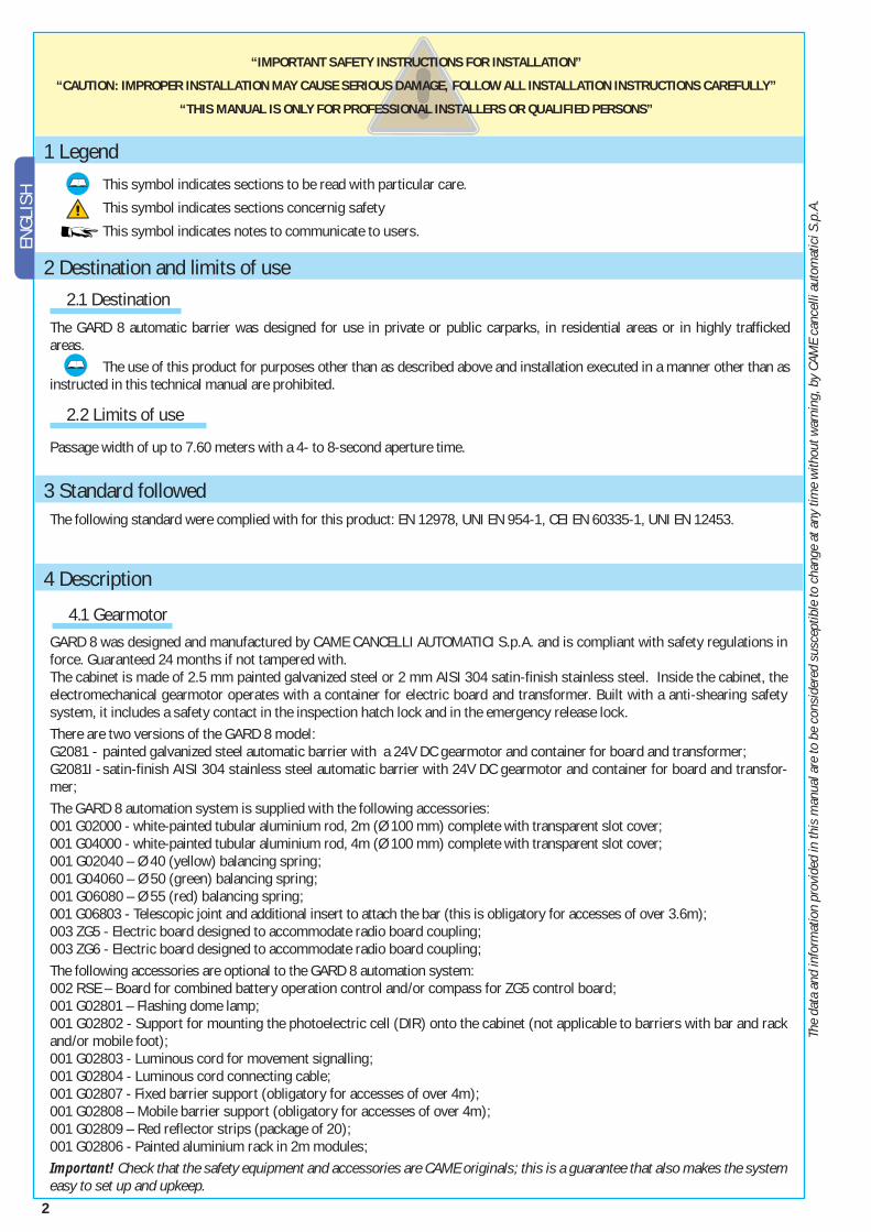
1 Legend This symbol indicates sections to be read with particular care.
This symbol indicates sections concernig safety
This symbol indicates notes to communicate to users.
GARD 8 was designed and manufactured by CAME CANCELLI AUTOMATICI S.p.A. and is compliant with safety regulations in force. Guaranteed 24 months if not tampered with.The cabinet is made of 2.5 mm painted galvanized steel or 2 mm AISI 304 satin-finish stainless steel. Inside the cabinet, the electromechanical gearmotor operates with a container for electric board and transformer. Built with a anti-shearing safety system, it includes a safety contact in the inspection hatch lock and in the emergency release lock.There are two versions of the GARD 8 model:G2081 - painted galvanized steel automatic barrier with a 24V DC gearmotor and container for board and transformer;G2081I - satin-finish AISI 304 stainless steel automatic barrier with 24V DC gearmotor and container for board and transfor-mer;The GARD 8 automation system is supplied with the following accessories:001 G02000 - white-painted tubular aluminium rod, 2m (Ø 100 mm) complete with transparent slot cover;001 G04000 - white-painted tubular aluminium rod, 4m (Ø 100 mm) complete with transparent slot cover;001 G02040 – Ø 40 (yellow) balancing spring;001 G04060 – Ø 50 (green) balancing spring;001 G06080 – Ø 55 (red) balancing spring;001 G06803 - Telescopic joint and additional insert to attach the bar (this is obligatory for accesses of over 3.6m);003 ZG5 - Electric board designed to accommodate radio board coupling;003 ZG6 - Electric board designed to accommodate radio board coupling;The following accessories are optional to the GARD 8 automation system:002 RSE – Board for combined battery operation control and/or compass for ZG5 control board;001 G02801 – Flashing dome lamp;001 G02802 - Support for mounting the photoelectric cell (DIR) onto the cabinet (not applicable to barriers with bar and rack and/or mobile foot);001 G02803 - Luminous cord for movement signalling;001 G02804 - Luminous cord connecting cable;001 G02807 - Fixed barrier support (obligatory for accesses of over 4m);001 G02808 – Mobile barrier support (obligatory for accesses of over 4m);001 G02809 – Red reflector strips (package of 20);001 G02806 - Painted aluminium rack in 2m modules;Important! Check that the safety equipment and accessories are CAME originals; this is a guarantee that also makes the system easy to set up and upkeep.
4 Description
“IMPORTANT SAFETY INSTRUCTIONS FOR INSTALLATION”
“CAUTION: IMPROPER INSTALLATION MAY CAUSE SERIOUS DAMAGE, FOLLOW ALL INSTALLATION INSTRUCTIONS CAREFULLY”
“THIS MANUAL IS ONLY FOR PROFESSIONAL INSTALLERS OR QUALIFIED PERSONS”
4.1 Gearmotor
2.1 Destination
The following standard were complied with for this product: EN 12978, UNI EN 954-1, CEI EN 60335-1, UNI EN 12453.
2 Destination and limits of use
The GARD 8 automatic barrier was designed for use in private or public carparks, in residential areas or in highly traffi cked areas. The use of this product for purposes other than as described above and installation executed in a manner other than as instructed in this technical manual are prohibited.
3 Standard followed
2.2 Limits of use
Passage width of up to 7.60 meters with a 4- to 8-second aperture time.
3
The
data
and
info
rmat
ion
prov
ided
in th
is m
anua
l are
to b
e co
nsid
ered
sus
cept
ible
to c
hang
e at
any
tim
e w
ithou
t war
ning
, by
CAM
E ca
ncel
li au
tom
atic
i S.p
.A.
ENGLISH
14
12
81
2
3
4
5
79
11
13
10
CAMECAMECAMECAME
611
10
7
8 9
12
1
2 3
5
4
13
6
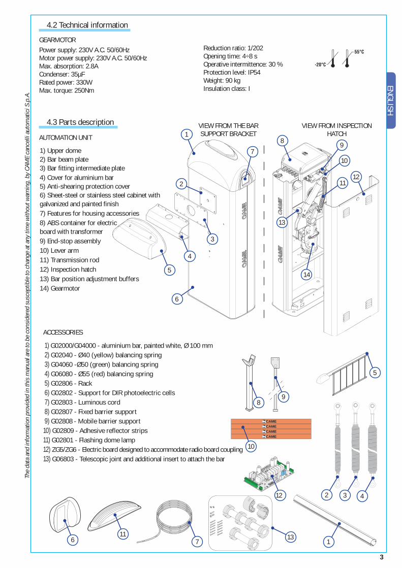
1) Upper dome2) Bar beam plate 3) Bar fitting intermediate plate4) Cover for aluminium bar5) Anti-shearing protection cover 6) Sheet-steel or stainless steel cabinet with galvanized and painted finish 7) Features for housing accessories8) ABS container for electric board with transformer 9) End-stop assembly10) Lever arm11) Transmission rod12) Inspection hatch13) Bar position adjustment buffers14) Gearmotor
4.2 Technical information
4.3 Parts description
AUTOMATION UNIT
ACCESSORIES
VIEW FROM THE BAR SUPPORT BRACKET
VIEW FROM INSPECTION HATCH
1) G02000/G04000 - aluminium bar, painted white, Ø 100 mm 2) G02040 - Ø40 (yellow) balancing spring 3) G04060 -Ø50 (green) balancing spring 4) G06080 - Ø55 (red) balancing spring 5) G02806 - Rack 6) G02802 - Support for DIR photoelectric cells 7) G02803 - Luminous cord 8) G02807 - Fixed barrier support 9) G02808 - Mobile barrier support10) G02809 - Adhesive reflector strips11) G02801 - Flashing dome lamp12) ZG5/ZG6 - Electric board designed to accommodate radio board coupling 13) G06803 - Telescopic joint and additional insert to attach the bar 11 -
Reduction ratio: 1/202Opening time: 4÷8 sOperative intermittence: 30 %Protection level: IP54Weight: 90 kgInsulation class: I
GEARMOTOR Power supply: 230V A.C. 50/60HzMotor power supply: 230V A.C. 50/60HzMax. absorption: 2.8A Condenser: 35µFRated power: 330WMax. torque: 250Nm
4
The
data
and
info
rmat
ion
prov
ided
in th
is m
anua
l are
to b
e co
nsid
ered
sus
cept
ible
to c
hang
e at
any
tim
e w
ithou
t war
ning
, by
CAM
E ca
ncel
li au
tom
atic
i S.p
.A.
ENGL
ISH
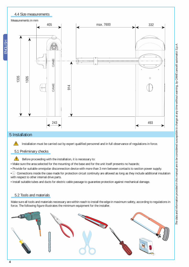
4.4 Size measurements
Before proceeding with the installation, it is necessary to:• Make sure the area selected for the mounting of the base and for the unit itself presents no hazards;• Provide for suitable omnipolar disconnection device with more than 3 mm between contacts to section power supply.• Connections inside the case made for protection circuit continuity are allowed as long as they include additional insulation with respect to other internal drive parts.• Install suitable tubes and ducts for electric cable passage to guarantee protection against mechanical damage.
Installation must be carried out by expert qualified personnel and in full observance of regulations in force.
5 Installation
5.1 Preliminary checks
5.2 Tools and materials
Make sure all tools and materials necessary are within reach to install the edge in maximum safety, according to regulations in force. The following figure illustrates the minimum equipment for the installer.
Measurements in mm
5
The
data
and
info
rmat
ion
prov
ided
in th
is m
anua
l are
to b
e co
nsid
ered
sus
cept
ible
to c
hang
e at
any
tim
e w
ithou
t war
ning
, by
CAM
E ca
ncel
li au
tom
atic
i S.p
.A.
ENGLISH
2
1
7
3
4
56
8
9
10
11
12
13
1415
16
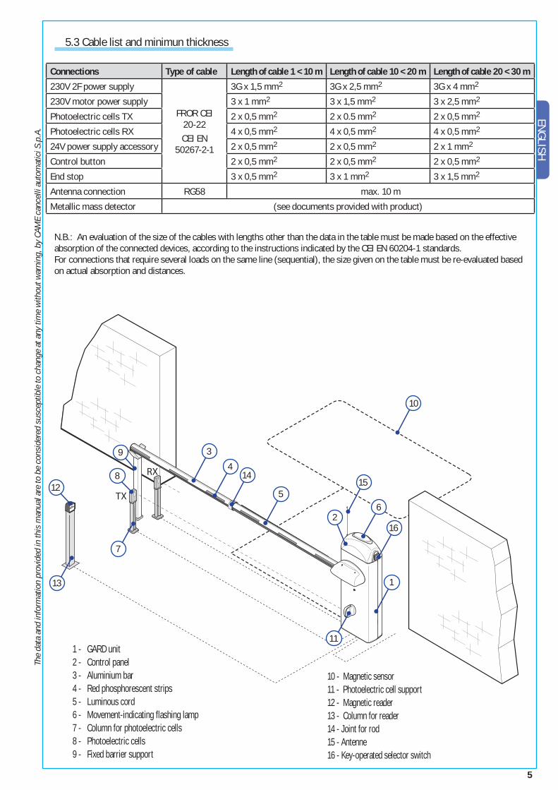
N.B.: An evaluation of the size of the cables with lengths other than the data in the table must be made based on the effective absorption of the connected devices, according to the instructions indicated by the CEI EN 60204-1 standards.For connections that require several loads on the same line (sequential), the size given on the table must be re-evaluated based on actual absorption and distances.
5.3 Cable list and minimun thickness
Connections Type of cable Length of cable 1 < 10 m Length of cable 10 < 20 m Length of cable 20 < 30 m
230V 2F power supply
FROR CEI 20-22 CEI EN
50267-2-1
3G x 1,5 mm2 3G x 2,5 mm2 3G x 4 mm2
230V motor power supply 3 x 1 mm2 3 x 1,5 mm2 3 x 2,5 mm2
Photoelectric cells TX 2 x 0,5 mm2 2 x 0.5 mm2 2 x 0,5 mm2
Photoelectric cells RX 4 x 0,5 mm2 4 x 0,5 mm2 4 x 0,5 mm2
24V power supply accessory 2 x 0,5 mm2 2 x 0,5 mm2 2 x 1 mm2
Control button 2 x 0,5 mm2 2 x 0,5 mm2 2 x 0,5 mm2
End stop 3 x 0,5 mm2 3 x 1 mm2 3 x 1,5 mm2
Antenna connection RG58 max. 10 m
Metallic mass detector (see documents provided with product)
1 - GARD unit 2 - Control panel 3 - Aluminium bar 4 - Red phosphorescent strips 5 - Luminous cord 6 - Movement-indicating flashing lamp 7 - Column for photoelectric cells 8 - Photoelectric cells 9 - Fixed barrier support
10 - Magnetic sensor11 - Photoelectric cell support12 - Magnetic reader13 - Column for reader14 - Joint for rod15 - Antenne16 - Key-operated selector switch
6
The
data
and
info
rmat
ion
prov
ided
in th
is m
anua
l are
to b
e co
nsid
ered
sus
cept
ible
to c
hang
e at
any
tim
e w
ithou
t war
ning
, by
CAM
E ca
ncel
li au
tom
atic
i S.p
.A.
ENGL
ISH
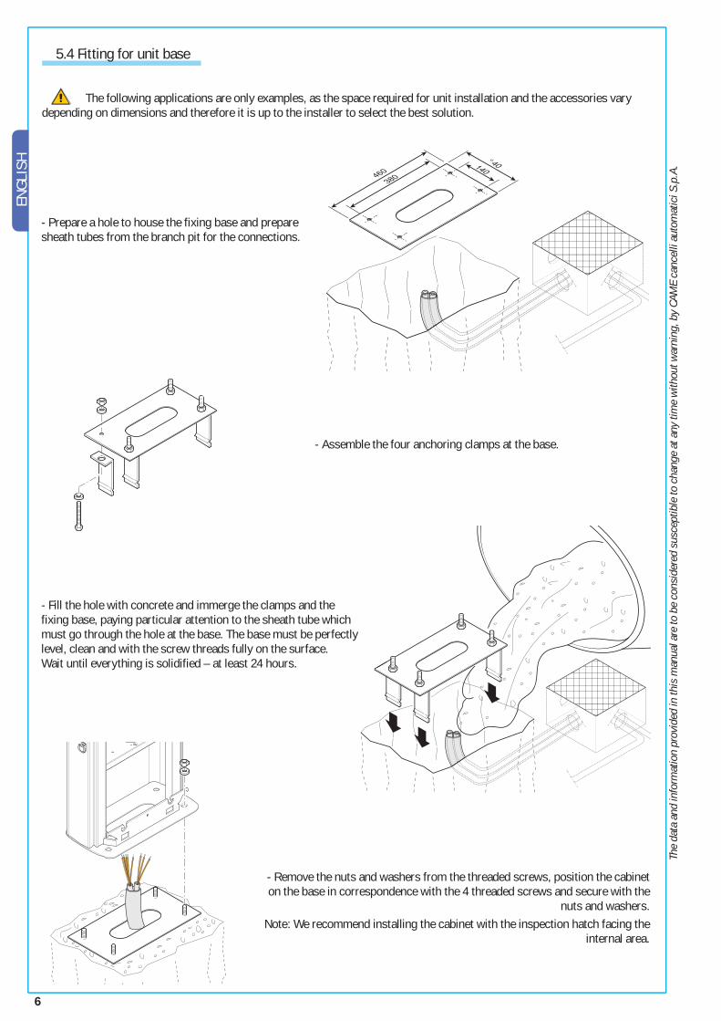
5.4 Fitting for unit base
The following applications are only examples, as the space required for unit installation and the accessories vary depending on dimensions and therefore it is up to the installer to select the best solution.
- Assemble the four anchoring clamps at the base.
- Prepare a hole to house the fixing base and prepare sheath tubes from the branch pit for the connections.
- Remove the nuts and washers from the threaded screws, position the cabinet on the base in correspondence with the 4 threaded screws and secure with the
nuts and washers. Note: We recommend installing the cabinet with the inspection hatch facing the
internal area.
- Fill the hole with concrete and immerge the clamps and the fixing base, paying particular attention to the sheath tube which must go through the hole at the base. The base must be perfectly level, clean and with the screw threads fully on the surface.Wait until everything is solidified – at least 24 hours.
7
The
data
and
info
rmat
ion
prov
ided
in th
is m
anua
l are
to b
e co
nsid
ered
sus
cept
ible
to c
hang
e at
any
tim
e w
ithou
t war
ning
, by
CAM
E ca
ncel
li au
tom
atic
i S.p
.A.
ENGLISH
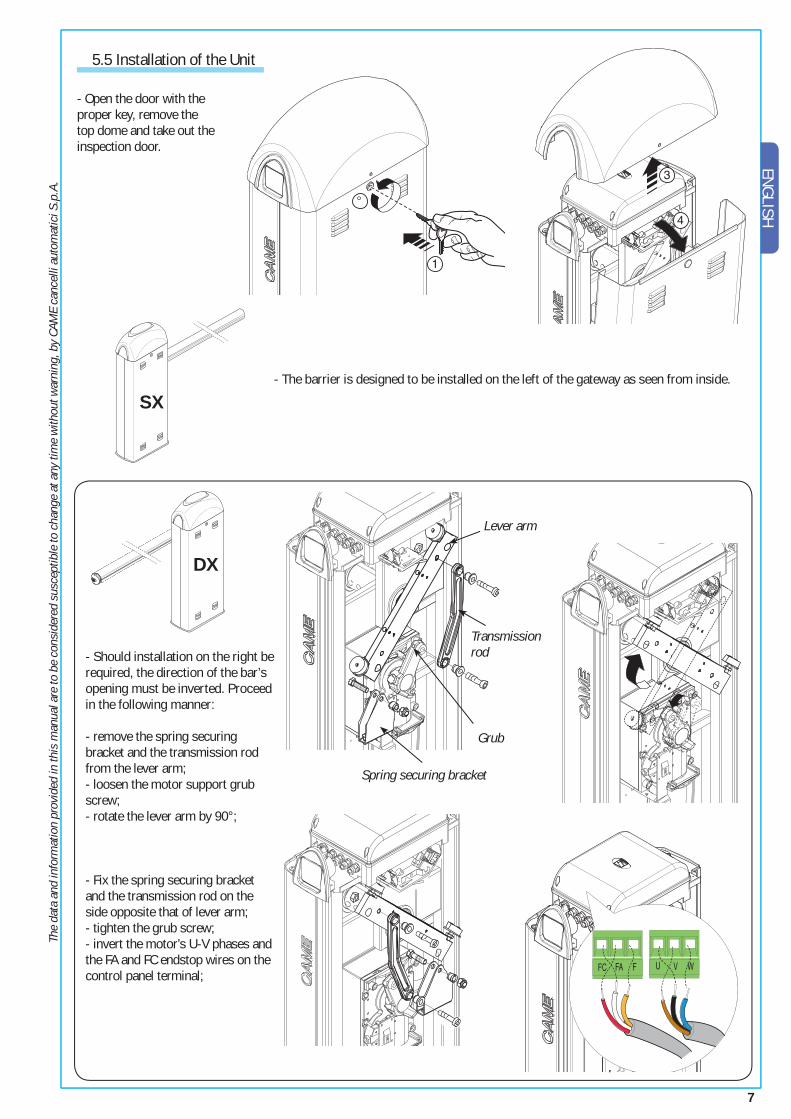
- Open the door with the proper key, remove the top dome and take out the inspection door.
DX
SX
- Should installation on the right be required, the direction of the bar’s opening must be inverted. Proceed in the following manner:
- remove the spring securing bracket and the transmission rod from the lever arm;- loosen the motor support grub screw;- rotate the lever arm by 90°;
- Fix the spring securing bracket and the transmission rod on the side opposite that of lever arm;- tighten the grub screw;- invert the motor’s U-V phases and the FA and FC endstop wires on the control panel terminal;
5.5 Installation of the Unit
- The barrier is designed to be installed on the left of the gateway as seen from inside.
Lever arm
Transmission rod
Spring securing bracket
Grub
8
The
data
and
info
rmat
ion
prov
ided
in th
is m
anua
l are
to b
e co
nsid
ered
sus
cept
ible
to c
hang
e at
any
tim
e w
ithou
t war
ning
, by
CAM
E ca
ncel
li au
tom
atic
i S.p
.A.
ENGL
ISH
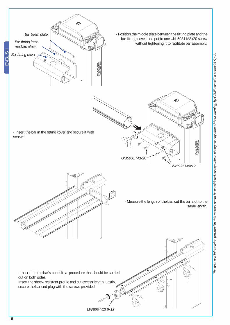
UNI5931 M8x20
UNI5931 M8x12
UNI6954 Ø2.9x13
- Measure the length of the bar, cut the bar slot to the same length.
- Position the middle plate between the fitting plate and the bar-fitting cover, and put in one UNI 5931 M8x20 screw
without tightening it to facilitate bar assembly.
- Insert it in the bar’s conduit, a procedure that should be carried out on both sides.Insert the shock-resistant profile and cut excess length. Lastly, secure the bar end plug with the screws provided.
- Insert the bar in the fitting cover and secure it with screws.
Bar beam plate
Bar fi tting inter-mediate plate
Bar fi tting cover
9
The
data
and
info
rmat
ion
prov
ided
in th
is m
anua
l are
to b
e co
nsid
ered
sus
cept
ible
to c
hang
e at
any
tim
e w
ithou
t war
ning
, by
CAM
E ca
ncel
li au
tom
atic
i S.p
.A.
ENGLISH
UNI6954 Ø3.9x19x12
Bare bar*
Bare bar* + mobile barrier support
Bare bar* + luminous cord
Bare bar* + luminous cord + mobile barrier support
Bare bar* + rack
Bare bar* + rack + luminous cord
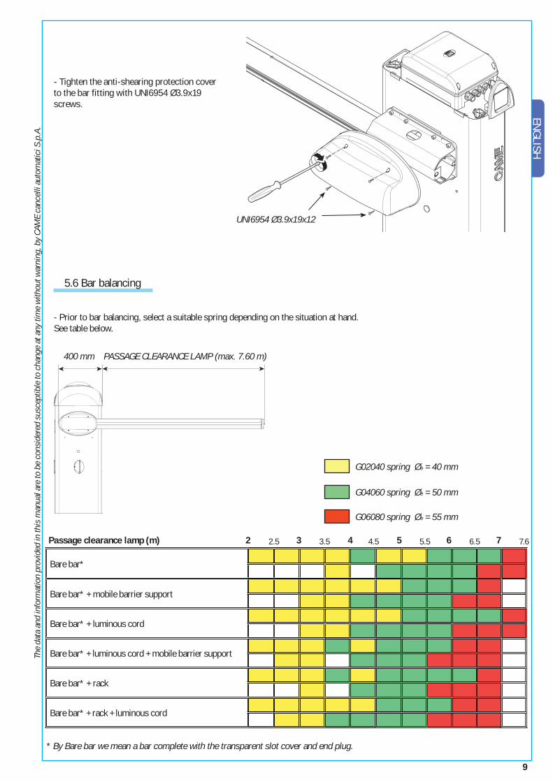
Passage clearance lamp (m) 2 2.5 3 3.5 4 4.5 5 5.5 6 6.5 7 7.6
* By Bare bar we mean a bar complete with the transparent slot cover and end plug.
400 mm
- Prior to bar balancing, select a suitable spring depending on the situation at hand. See table below.
- Tighten the anti-shearing protection cover to the bar fitting with UNI6954 Ø3.9x19 screws.
5.6 Bar balancing
PASSAGE CLEARANCE LAMP (max. 7.60 m)
G02040 spring Øe = 40 mm
G04060 spring Øe = 50 mm
G06080 spring Øe = 55 mm
10
The
data
and
info
rmat
ion
prov
ided
in th
is m
anua
l are
to b
e co
nsid
ered
sus
cept
ible
to c
hang
e at
any
tim
e w
ithou
t war
ning
, by
CAM
E ca
ncel
li au
tom
atic
i S.p
.A.
ENGL
ISH
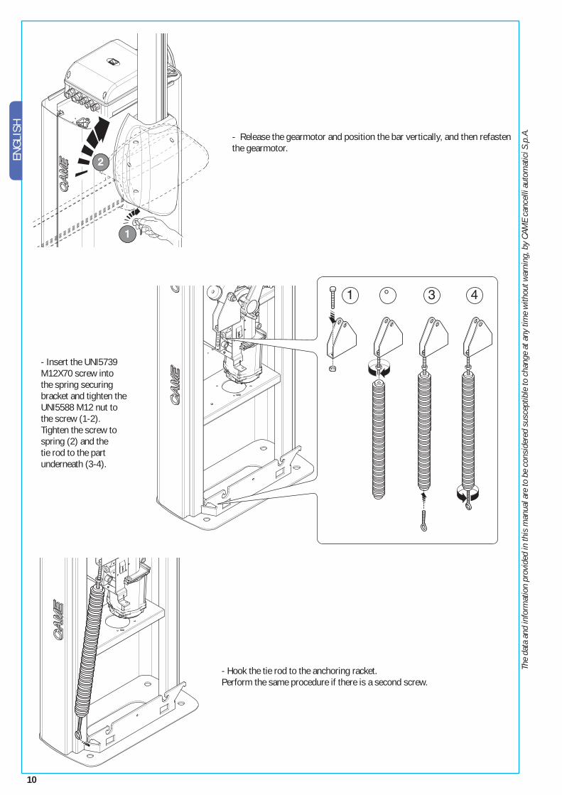
- Release the gearmotor and position the bar vertically, and then refasten the gearmotor.
- Hook the tie rod to the anchoring racket.Perform the same procedure if there is a second screw.
- Insert the UNI5739 M12X70 screw into the spring securing bracket and tighten the UNI5588 M12 nut to the screw (1-2).Tighten the screw to spring (2) and the tie rod to the part underneath (3-4).
11
The
data
and
info
rmat
ion
prov
ided
in th
is m
anua
l are
to b
e co
nsid
ered
sus
cept
ible
to c
hang
e at
any
tim
e w
ithou
t war
ning
, by
CAM
E ca
ncel
li au
tom
atic
i S.p
.A.
ENGLISH
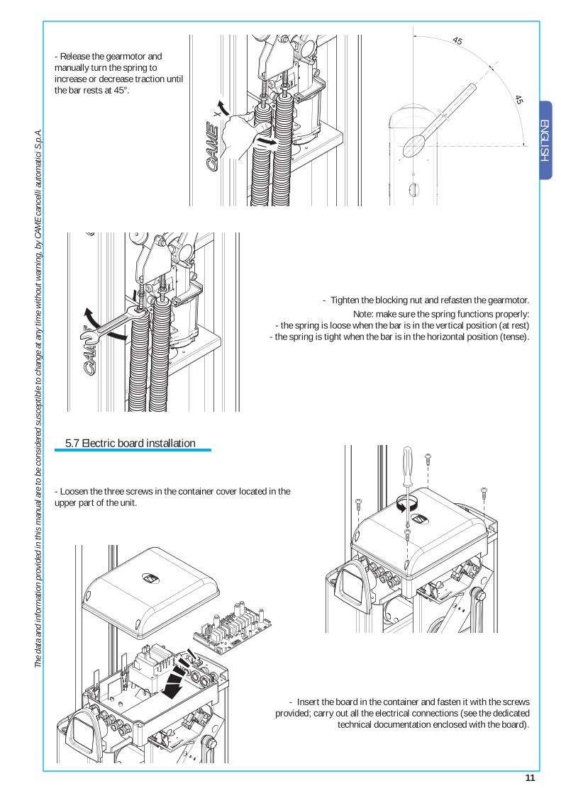
- Release the gearmotor and manually turn the spring to increase or decrease traction until the bar rests at 45°.
- Tighten the blocking nut and refasten the gearmotor.Note: make sure the spring functions properly:
- the spring is loose when the bar is in the vertical position (at rest) - the spring is tight when the bar is in the horizontal position (tense).
5.7 Electric board installation
- Loosen the three screws in the container cover located in the upper part of the unit.
- Insert the board in the container and fasten it with the screws provided; carry out all the electrical connections (see the dedicated
technical documentation enclosed with the board).
12
The
data
and
info
rmat
ion
prov
ided
in th
is m
anua
l are
to b
e co
nsid
ered
sus
cept
ible
to c
hang
e at
any
tim
e w
ithou
t war
ning
, by
CAM
E ca
ncel
li au
tom
atic
i S.p
.A.
ENGL
ISH
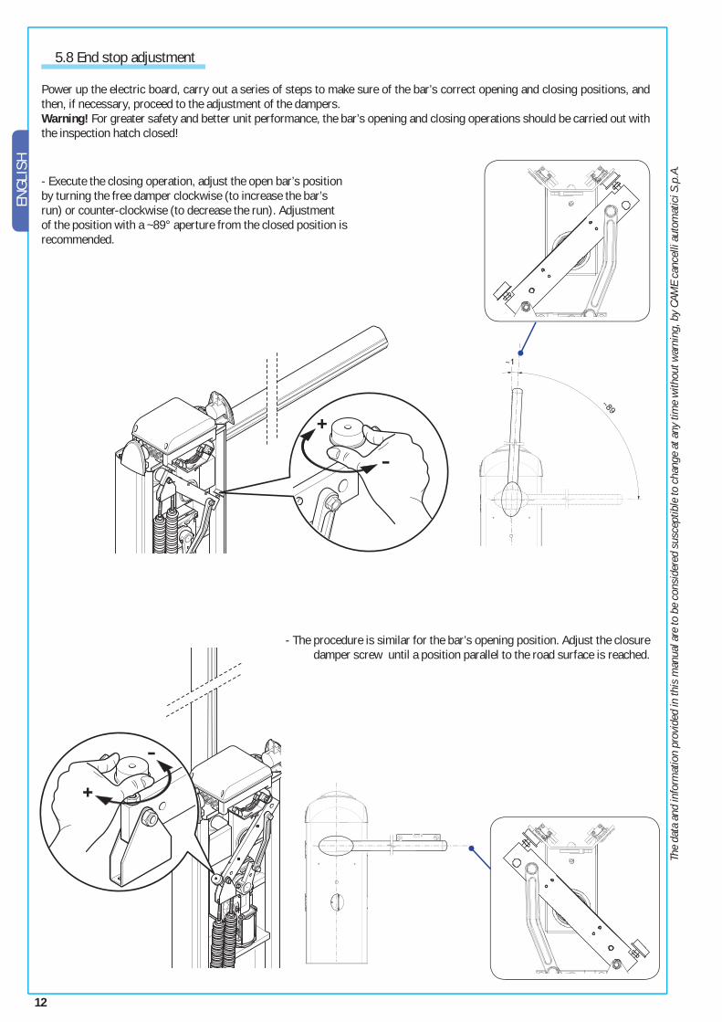
- The procedure is similar for the bar’s opening position. Adjust the closure damper screw until a position parallel to the road surface is reached.
5.8 End stop adjustment
Power up the electric board, carry out a series of steps to make sure of the bar’s correct opening and closing positions, and then, if necessary, proceed to the adjustment of the dampers.Warning! For greater safety and better unit performance, the bar’s opening and closing operations should be carried out with the inspection hatch closed!
- Execute the closing operation, adjust the open bar’s position by turning the free damper clockwise (to increase the bar’s run) or counter-clockwise (to decrease the run). Adjustment of the position with a ~89° aperture from the closed position is recommended.
13
The
data
and
info
rmat
ion
prov
ided
in th
is m
anua
l are
to b
e co
nsid
ered
sus
cept
ible
to c
hang
e at
any
tim
e w
ithou
t war
ning
, by
CAM
E ca
ncel
li au
tom
atic
i S.p
.A.
ENGLISH
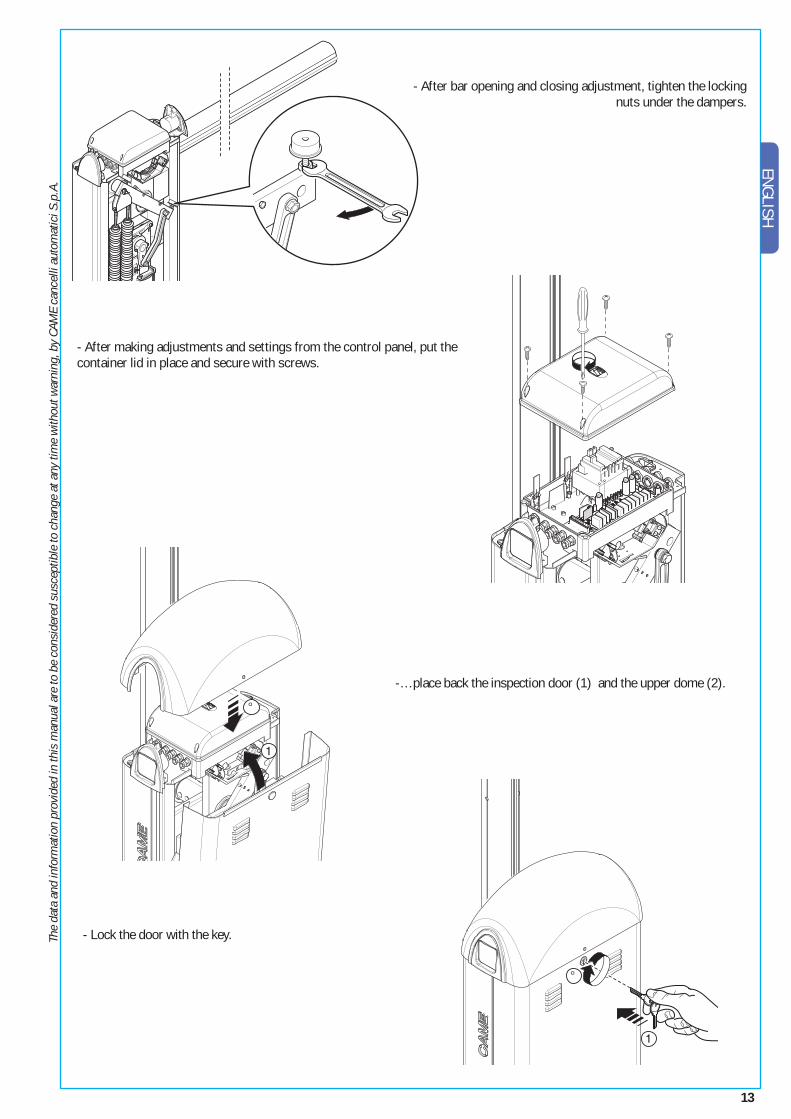
-…place back the inspection door (1) and the upper dome (2).
- Lock the door with the key.
- After bar opening and closing adjustment, tighten the locking nuts under the dampers.
- After making adjustments and settings from the control panel, put the container lid in place and secure with screws.
14
The
data
and
info
rmat
ion
prov
ided
in th
is m
anua
l are
to b
e co
nsid
ered
sus
cept
ible
to c
hang
e at
any
tim
e w
ithou
t war
ning
, by
CAM
E ca
ncel
li au
tom
atic
i S.p
.A.
ENGL
ISH
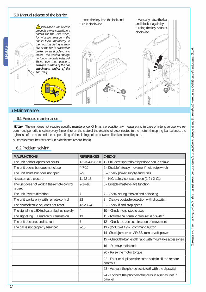
WARNING! The release procedure may constitute a hazard for the user when, for whatever reason – the bar is fixed improperly to the housing during assem-bly, or the bar is cracked or broken in an accident, and so on – the tension springs no longer provide balance! These can thus cause a brusque rotation of the bar attachment and/or of the bar itself.
5.9 Manual release of the barrier
MALFUNCTIONS REFERENCES CHECKS
The unit neither opens nor shuts 1-2-3-4-6-8-20 1 - Chiudere sportello d’ispezione con la chiave
The unit opens but does not close 4-7-10 2 - Disable “steady movement” with dipswitch
The unit shuts but does not open 7-9 3 – Check power supply and fuses
No automatic closure 11-12-13 4 - N.C. safety contacts open (1-2 / 2-C1)
The unit does not work if the remote control is used
2-14-16 6 - Disable master-slave function
The unit inverts direction 7 7 – Check spring tension and balancing
The unit works only with remote control 22 8 – Disable obstacle detection with dipswitch
The photoelectric cell does not react 12-23-24 9 – Check if end stop opens
The signalling LED indicator flashes rapidly 4 10 – Check if end stop closes
The signalling LED indicator remains on 13 11 - Activate “automatic closure” dip switch
The unit does not end its run 7 12 – Check the correct direction of movement
The bar is not properly balanced 7-15 13 - (2-3 / 2-4 / 2-7) command button
14 -Check jumper on AF43S, turn on/off power
15 – Check the bar length ratio with mountable accessories
16 – Re-save radio code
20 - Raise the motor torque
22 - Enter or duplicate the same code in all the remote controls
23 - Activate the photoelectric cell with the dipswitch
24 - Connect the photoelectric cells in a series, not in parallel
6.1 Periodic maintenance
The unit does not require specifi c maintenance. Only as a precautionary measure and in case of intensive use, we re-commend periodic checks (every 6 months) on the state of the electric wire connected to the motor, the spring-bar balance, the tightness of the nuts and the proper oiling of the sliding points between fi xed and mobile parts.All checks must be recorded (in a dedicated record-book).
6 Maintenance
6.2 Problem solving
- Manually raise the bar and block it again by turning the key counter-clockwise.
- Insert the key into the lock and turn it clockwise.
15
The
data
and
info
rmat
ion
prov
ided
in th
is m
anua
l are
to b
e co
nsid
ered
sus
cept
ible
to c
hang
e at
any
tim
e w
ithou
t war
ning
, by
CAM
E ca
ncel
li au
tom
atic
i S.p
.A.
ENGLISH
In its premises, CAME CANCELLI AUTOMATICI S.p.A. implements an Environmental Management System certifi ed in compliance with the UNI EN ISO 14001 standard to ensure environmental protection.Please continue our efforts to protect the environment—which CAME considers one of the cardinal elements in the development of its operational and market strategies—simply by observing brief recommendations as regards disposal: DISPOSAL OF PACKAGING – The packaging components (cardboard, plastic, etc.) are all classifi able as solid urban waste products and may be disposed of easily, keeping in mind recycling possibilities.Prior to disposal, it is always advisable to check specifi c regulations in force in the place of installation.PLEASE DISPOSE OF PROPERLY! PRODUCT DISPOSAL – Our products are made up of various types of materials. Most of them (aluminium, plastics, iron, electrical wires, etc.) may be disposed of in normal garbage collection bins and can be recycled by disposing of in specifi c re-cyclable material collection bins and disposal in authorized centres. Other components (electrical boards, remote control batteries, etc.), however, may contain polluting substances. They should therefore be removed and given to qualifi ed service companies for proper disposal.Prior to disposal, it is always advisable to check specifi c regulations in force in the place of disposal.PLEASE DISPOSE OF PROPERLY!
7 Demolition and disposal
MANUFACTURER’S DECLARATION OF CONFORMITYPursuant to annex II B of the Machinery Directive 98/37/EC
CAME Cancelli Automatici S.p.A. via Martiri della Libertà, 15 31030 Dosson di Casier - Treviso - ITALY tel (+39) 0422 4940 - fax (+39) 0422 4941 internet: www.came.it - e-mail: [email protected]
Declares under its own responsibility that the equipments for automatic garage doors and gates listed below:
… comply with the National Law related to the following European Directives and to the applicable parts of the following Standards.
98/37/CE - 98/79/CE MACHINERY DIRECTIVE 98/336/CEE - 92/31/CEE ELECTROMAGNETIC COMPATIBILITY DIRECTIVE
73/23/CEE - 93/68/CE LOW VOLTAGE DIRECTIVE
89/106/CEE CONSTRUCTION PRODUCTS DIRECTIVE
EN 13241-1 EN 12635 EN 61000-6-2 EN 12453 EN 12978 EN 61000-6-3 EN 12445 EN 60335-1 EN 60204-1
IMPORTANT WARNING!Do not use the equipment specifi ed here above, before completing the full installation
In full compliance with the Machinery Directive 98/37/EC
MANAGING DIRECTORMr. Andrea Menuzzo
8 Manufacturer’s warranty
Reference code to request a true copy of the original: DDF B EN G001 ver.1.0
AUTOMATION FOR STREET BARRIERS
G2081 - G2081I
CONTAINING SOME OF THE FOLLOWING ACCESSORIESG02000 - G04000 - G02040 - G04060 - G06080 - G06803
G02801 - G02802 - G02803 - G02804 - G02806 - G02807- G02808 - G02809
Cod.
119
GT41
ver
. 1.0
06/
06 ©
CAM
E CA
NCEL
LI A
UTOM
ATIC
I
CAME UNITED KINGDOM LTDUNIT 3, ORCHARD BUSINESS PARK TOWN
STREET, SANDIACRE NOTTINGHAM - NG10 5BP - U.K.
Tel 0044 115 9210430
Fax 0044 115 9210431


