AUTOMATIKA - TU Wien · AUTOMATIKA . Journal for Control, Measurement, Electronics, Computing and...
17
Author's personal copy
Transcript of AUTOMATIKA - TU Wien · AUTOMATIKA . Journal for Control, Measurement, Electronics, Computing and...

Author's personal copy

AUTOMATIKA Journal for Control, Measurement, Electronics, Computing and Communications Online ISSN 1848-3380, Print ISSN 0005-1144, doi: 10.7305, UDK 007:62/68
ATKAAF 54(3), 282–379 (2013) Volume 54, No. 3, July–September 2013
Published quarterly by KoREMA – Croatian Society for Communications, Computing, Electronics, Measurement and Control, Member of IFAC
Partly financed by the Ministry of Science, Education and Sports of the Republic of Croatia
Abstracted/Indexed in Science Citation Index Expanded, SCOPUS, EBSCO and INSPEC (Institution of Electrical Engineers)
EDITORIAL BOARD
Editor-in-Chief Ivan Petrović
University of Zagreb, Faculty of Electrical Engineering and Computing, Croatia
Honorary Editor-in-Chief Borivoje Rajković
Končar - Electrical Engineering Institute, Croatia
Associate Editors Mato Baotić University of Zagreb, Croatia Vedran Bilas University of Zagreb, Croatia Joško Deur University of Zagreb, Croatia
Zdenko Kovačić University of Zagreb, Croatia Miro Milanović University of Maribor, Slovenia
Davor Petrinović University of Zagreb, Croatia Zvonimir Šipuš University of Zagreb, Croatia
Editors
Morgens Blanke Aalborg University, Denmark Nikola Bogunović University of Zagreb, Croatia Davor Bonefačić University of Zagreb, Croatia Dali Đonlagić University of Maribor, Slovenia Branko Jeren University of Zagreb, Croatia Branko Katalinić Vienna University of Technology, Austria
Werner Leonhard Technical University Braunschweig, Germany Gabor Matay Budapest University of Technology and Economics, Hungary Jadranko Matuško University of Zagreb, Croatia Sanjit K. Mitra University of California, USA Borivoj Modlic University of Zagreb, Croatia Mario Vašak University of Zagreb, Croatia
Lucio Vegni University of Roma Tre, Italy Dana Kulić University of Waterloo, Canada Luis Martínez Salamero University “Rovira i Virgili” of Tarragona, Spain Mislav Grgić University of Zagreb, Croatia Marija Đakulović University of Zagreb, Croatia
PUBLISHING COUNCIL
Nedjeljko Perić, Chair University of Zagreb, Croatia Hrvoje Babić Croatian Academy of Sciences and Arts, Croatia Leo Budin Croatian Academy of Sciences and Arts, Croatia
Dali Đonlagić University of Maribor, Slovenia Bernard Franković University of Rijeka, Croatia Martin Jadrić University of Split, Croatia Drago Matko University of Ljubljana, Slovenia
Anton Ogorelec University of Ljubljana, Slovenia Borivoje Rajković Končar - Electrical Engineering Institute, Croatia Asif Šabanović Sabancı University, Turkey Hideki Hashimoto University of Tokyo, Japan
EDITORIAL OFFICE AND JOURNAL ADMINISTRATION
Journal Preparation for Print: Ivan Marković, coordinator, Vedran Bobanac, Tamara Hadjina, Domagoj Herceg, Nikola Hure, Vinko Lešić, Ivan Maurović, Vlaho Petrović
Print: Prodigital, HR-10000 Zagreb, 1. Trnjanski zavoj 5, Croatia Manuscript Submission System: Srećko Jurić-Kavelj
Journal subscription and Advertisement announcement information: Marina Štimec, KoREMA Secretary
KoREMA Secretariat and Journal Address: KoREMA (for journal Automatika), Unska 3, 10000 Zagreb, Croatia
Phone: ++(385 1) 6129 869, Fax: ++(385 1) 6129 870 E-mail: [email protected], URL: http://automatika.korema.hr
JOURNAL FOR CONTROL, MEASUREMENT, ELECTRONICS,COMPUTING AND COMMUNICATIONS
Published by KoREMA Zagreb, CroatiaMember of IFAC
doi: 10.7305Online ISSN 1848-3380Print ISSN 0005–1144ATKAAF 54(3), 282–379 (2013) Volume 54–2013UDK: 007:62/68 No 3
CONTENTS
286 Editorial
Felix A. Himmelstoss, Sergey E.Ryvkin
290 DC/DC Converter for Motor Drive – Concept, Design, andFeed-Forward Controloriginal scientific paper
Branislav Dobrucky, MarianaBenova, Mahmud Abdalmula,Slavomir Kašcák
299 Design Analysis of LCTLC Resonant Inverter for Two-Stage2-Phase Supply Systemoriginal scientific paper
Marek Pástor, Jaroslav Dudrik 308 Predictive Current Control of Grid-tied Cascade H-bridge Inverteroriginal scientific paper
Vinko Lešic, Mario Vašak, NedjeljkoPeric, Thomas M. Wolbank, GojkoJoksimovic
316 Fault-tolerant Control of a Wind Turbine with a Squirrel-cageInduction Generator and Rotor Bar Defectsoriginal scientific paper
Mateusz Dybkowski, TeresaOrlowska-Kowalska, GrzegorzTarchala
329 Sensorless Traction Drive System with Sliding Mode and MRASCC
Estimators using Direct Torque Controloriginal scientific paper
Ján Vittek, Vladimir Vavrúš, PeterBriš, Lukáš Gorel
337 Forced Dynamics Control of the Elastic Joint Drive with SingleRotor Position Sensororiginal scientific paper
Czeslaw T. Kowalski, RobertWierzbicki, Marcin Wolkiewicz
348 Stator and Rotor Faults Monitoring of the Inverter-Fed InductionMotor Drive using State Estimatorsoriginal scientific paper

Karol Kyslan, František Durovsky 356 Dynamic Emulation of Mechanical Loads – An Approach Based onIndustrial Drives’ Featuresoriginal scientific paper
Danijel Pavkovic, NenadKranjcevic, Milan Kostelac
364 Design of Normal Force Control System for a Pin-on-DiskTribometer including Active and Passive Suppression of VerticalVibrationsoriginal scientific paper
376 IFAC Newsletter

Vinko Lešic, Mario Vašak, Nedjeljko Peric, Thomas M. Wolbank, Gojko Joksimovic
Fault-tolerant Control of a Wind Turbine with a Squirrel-cageInduction Generator and Rotor Bar Defects
DOIUDKIFAC
10.7305/automatika.54-3.189681.532.5.09:621.313.33(621.224)2.1.4; 5.5.4
Original scientific paper
Wind turbines are usually installed on remote locations and in order to increase their economic competencemalfunctions should be reduced and prevented. Faults of wind turbine generator electromechanical parts are co-mmon and very expensive. This paper proposes a fault-tolerant control strategy for variable-speed variable-pitchwind turbines in case of identified and characterised squirrel-cage generator rotor bar defect. An upgrade of thetorque control loop with flux-angle-based torque modulation is proposed. In order to avoid or to postpone generatorcage defects, usage of pitch controller in the low wind speed region is introduced. Presented fault-tolerant controlstrategy is developed taking into account its modular implementation and installation in available control systemsof existing wind turbines to extend their life cycle and energy production. Practical implementation aspects suchas estimation of variables used in control and estimate errors are considered and respected in operation, as well asfault-induced asymmetries. Simulation results for the case of a megawatt class wind turbine and the identified rotorbar fault are presented.
Key words: Wind turbine control, Torque control, Generator fault-tolerant control, Nonlinear estimation, Asymm-etric field-oriented control
Upravljanje vjetroagregatom otporno na oštecenja kaveza asinkronog generatora. Vjetroagregati se obicnopostavljaju na udaljene, nepristupacne lokacije te je potrebno sprijeciti nastanak kvarova da bi se povecala njihovaekonomska konkurentnost. Kvarovi elektromehanickih dijelova generatora vjetroagregata cesti su i vrlo skupi. Uovom radu predstavljen je koncept upravljanja vjetroagregatima s promjenjivom brzinom vrtnje i zakretom lopaticaza slucaj identificiranog i okarakteriziranog oštecenja kaveza asinkronog generatora. Predložena je nadogradnjana postojeci algoritam upravljanja momentom zasnovana na njegovoj modulaciji s obzirom na položaj magnet-skog toka generatora. Da bi se izbjeglo ili usporilo širenje napuknuca kaveza generatora, predložena je primjenaregulacijskog kruga za zakret lopatica i u režimu rada vjetroagregata ispod nazivne brzine vrtnje. Predstavljenastrategija upravljanja razvijena je uvažavajuci mogucnost modularnog nadovezivanja na postojece metode uprav-ljanja vec postavljenih vjetroagregata s ciljem produženja njihova životnog vijeka i povecanja proizvodnje energije.Razmatrani su i uvaženi aspekti vezani uz prakticnu izvedbu, kao što je estimacija varijabli korištenih u upravlja-ckom algoritmu i pripadajuce pogreške estimata, kao i nesimetrije uzrokovane nastankom kvara. U radu su danisimulacijski rezultati za slucaj vjetroagregata iz megavatne klase s dijagnosticiranim napuknucem kaveza rotora.
Kljucne rijeci: upravljanje vjetroagregatom, upravljanje momentom, upravljanje otporno na kvarove generatora,nelinearna estimacija, vektorsko upravljanje nesimetricnog stroja
1 INTRODUCTION
Aspiration for finding adequate substitute for conven-tional fossil fuel power systems has a great impact on todaypolitical and economic trends and guidelines. Combiningdifferent branches of science and engineering, wind energyis one of the fastest-growing renewable energy sourceswith an average growth rate of 26% in last 5 years [1].It is green, inexhaustible, everywhere available but unreli-able with poor power quality and as a result – expensive.
The challenge is to make wind turbine control system capa-ble of maximising the energy production and the producedenergy quality while minimising costs of installation andmaintenance.
Wind turbines are usually installed at low-turbulent-wind remote locations and it is important to avoid verycostly unscheduled repairs. In order to improve reliabilityof wind turbines, different fault-tolerant control (FTC) al-gorithms have been introduced [2], focused mainly on sen-
Online ISSN 1848-3380, Print ISSN 0005-1144ATKAFF 54(3), 316–328(2013)
316 AUTOMATIKA 54(2013) 3, 316–328
Fault-tolerant Control of a Wind Turbine with Induction Generator Rotor Bar Defects V. Lešic, M. Vašak, N. Peric, T. M. Wolbank, G. Joksimovic
sor, inverter and actuator faults. Focus here is on generatorelectromechanical faults, which are besides gearbox andpower converters faults the most common in wind turbinesystems [3]. Many installed wind turbines have squirrel-cage induction generator (SCIG) and about 20% to 30% ofmachine faults are caused by defects in rotor cage [4].
Rotor bar defect is caused by thermal fatigue due tocyclic thermal stress on the endring-bar connection whichoccurs because of different thermal coefficients of bars andlamination steel. As presented in [5, 6], a monitoring sys-tem that is able to detect a developing bar defect is de-signed based on current signature analysis and offers thepossibility to switch from preventive to predictive mainte-nance and thus to significantly reduce costs.
Focus of this paper is to research and develop a fault-tolerant extension of the wind turbine control system thatprevents the identified rotor bar defect from spreading. Weintroduce a fast control loop for flux-angle-based modula-tion of the generator torque, and a slow control loop thatensures the generator placement at a point that enables thefast loop to perform correctly and keeps the electrical en-ergy production optimal under emergency circumstances.
The basic concept of the generator FTC is proposedin [7]. Here we further improve the idea and develop thealgorithm by considering practical implementation aspectssuch as how state estimation techniques are combined withthe derived FTC strategy. State estimation error is antici-pated in the FTC in order to guarantee safe operation inits presence. Unscented Kalman filter approach is chosenfor estimation of variables that are needed in wind turbinegenerator torque control because of its proficient ability tocope with hard nonlinearites. A paper that concerns withinfluence of parameter variation on machine control andtheir estimation is presented in [8].
Occurred rotor bar fault introduces changes in cla-ssical mathematical model of the induction machine. Amethod for modeling changes in machine leakage induc-tance is proposed and the fault influence is respected inthe control. The method presents an upgrade of conven-tional fundamental-wave approach in machine modelingand control. A similar work related with asymmetriescaused by a stator inter-turn fault can be found in [9].
This paper is organized as follows. The basic controlstrategy for a variable-speed variable-pitch wind turbineis presented in Section 2 along with normal wind turbineoperating maps. In Section 3 a mathematical model of anSCIG is given explaining the theoretical basis used to forma control system extension. Estimation of machine vari-ables used for torque control is described in Section 4.A fault-tolerant approach and control algorithm are pro-posed and presented in Section 5. They enable wind tur-bine operation in emergency state with estimation error
taken into account. Section 6 concerns with changes ofthe SCIG model due to occurred fault. Section 7 providesMATLAB/Simulink simulation results obtained with theproposed fault-tolerant control strategy.
2 WIND TURBINE CONTROL SYSTEM
Variable-speed variable-pitch wind turbine operatingarea is parted into two regions (see Fig. 1): low-wind-speed region (region I), where all the available wind poweris fully captured and high-wind-speed region (region II)where the power output is maintained constant while re-ducing the aerodynamic torque and keeping generatorspeed at the rated value.
Vm i n Vm axVN
V (m / s)
Pow
er
PN
I I I
PNB
VBmaxVNB
Fig. 1. Ideal power curve with maximum PN and powercurve due to developed fault with maximum PNB
The ability of a wind turbine to capture wind energyis expressed through a power coefficient CP , which is de-fined as the ratio of extracted power Pt to wind power PV :
CP =PtPV
. (1)
The maximum value of CP , known as Betz limit, isCPmax = 0.593. It defines the maximum theoretical capa-bility of wind power capture. The real power coefficient ofmodern commercial wind turbines reaches values of about0.48 [10]. Power coefficient data is usually given as a func-tion of the tip-speed-ratio λ and pitch angle β (Fig. 2). Tur-bine power and torque are given by [11]:
Pt = CP (λ, β)PV =1
2ρairR
2πCP (λ, β)V 3, (2)
Tt =Ptω
=1
2ρairR
3πCQ(λ, β)V 2, (3)
where CQ = CP /λ, ρair, R, V and ω are torque coeffi-cient, air density, radius of the aerodynamic disk of a windturbine, wind speed and the angular speed of blades, re-spectively, and λ = ωR
V .
Since the goal is to maximise the output power in low-wind-speed region, wind turbine must operate such that thepower coefficient CP is at its maximum value (or near it).This is achieved by maintaining λ and β on values thatensure CP = CPmax [10–12], see Fig. 2. Therefore the
AUTOMATIKA 54(2013) 3, 316–328 317

Fault-tolerant Control of a Wind Turbine with Induction Generator Rotor Bar Defects V. Lešic, M. Vašak, N. Peric, T. M. Wolbank, G. Joksimovic
CPmax
30
150
0.5
β λ
0
0 30
15
0
0.08
0
0β λ
a) b)
Fig. 2. Power a) and torque b) coefficients for an exemplary700 kW variable-speed variable-pitch wind turbine
generator torque and consequently the aerodynamic torqueis determined by:
Tgref =1
2λ3optn3s
ρairπR5CPmaxω
2g = Kλω
2g , (4)
where ns is the gearbox ratio. This way the wind turbineoperating points in low wind speed region are located at themaximum output power curve, called CPmax locus. ThisTgref = Kλω
2g torque controller (Fig. 3) can be easily re-
alized using a simple look-up table.
ωref+-
ω
ω
βref β
Tgref Tg
PITCH servo& controller
SPEEDcontroller
TORQUEcontroller
GENERATOR & INVERTER
WIND ω
Fig. 3. Control system of a variable-speed variable-pitchwind turbine
Above the designated rated wind speed, task of the con-trol system is to maintain the output power of the windturbine constant. This can be done by reducing the aerody-namic torque and angular speed of blades by rotating themalong their longitudinal axis (pitching). Consequently, thewind turbine power coefficient is reduced. A proportional-integral (PI) or proportional-integral-derivative (PID) con-troller with gain-scheduling technique is often satisfactoryfor pitch control (Fig. 3).
3 MATHEMATICAL MODEL OF AN INDUCTIONMACHINE
There are several approaches in modelling an inductionmachine [13]. One of the most common is the representa-tion of machine stator and rotor phases in the two-phase co-mmon rotating (d, q) coordinate system, which is suitable
for field-oriented control application. A rotor-based field-oriented control (RFOC) implies that the common rotating(d, q) frame is aligned with rotor flux linkage:
ψr = ψrd + j0, (5)
and the complex value of ψr becomes a scalar ψrd.Mathematical model of a squirrel-cage induction
machine used for RFOC can be represented with the foll-owing equations [13]:
usd = ksisd + Lldisddt
+
(LlTr− LsTr
)imr − ωeLlisq, (6)
usq = Rsisq + Lldisqdt− ωe (Ll − Ls) imr + ωeLlisd, (7)
where usd,q are stator voltages in d and q axes, isd,q arestator currents, imr is the rotor magnetizing current. Pa-rameter Tr = Lr
Rris the rotor time constant, parameters
Lr, Ls and Lm are rotor, stator and mutual inductance,respectively, Rr and Rs are rotor and stator resistances,Ll = (Ls− L2
m
Lr), ks = (Rs− Ll
Tr+ LsTr
). Variable ωe = 2πfdenotes the speed of machine magnetizing flux rotationwith respect to the stator, where f is the frequency of volt-age supplied by the inverter. Terms with ωe in (6) and (7)represent the machine back-electromotive force (EMF).
RFOC equations are given by:
imr =ψrdLm
, (8)
isd = imr + Trdimrdt
, (9)
ωsl = ωe − pωg, (10)
Tg =3
2pL2m
Lrimrisq = kmimrisq, (11)
where ωsl =isq
Trimris the slip speed calculated as a dif-
ference between the magnetic flux rotation speed ωe andreal rotor mechanical speed ωg multiplied by the numberof stator pole pairs p. The variable ωsl with its sign dictateswhether the asynchronous machine is in the motor or in thegenerator operating regime.
Relation (11) is the key equation for RFOC of an induc-tion machine. Following from (9), the magnetizing currentvector imr is not suitable for fast control action influenc-ing torque because of the time lag Tr. Therefore it is keptconstant in the sub-nominal speed operating region andimr , isd , isdn is implied, where isdn is the rated valueof d-current corresponding to the rated flux value. Torqueis controlled only by q stator current component (isq).
Relations (6) and (7) show that d and q coordinatesare not fully decoupled for the case of voltage-controlledmachine (Fig. 4) and changing the voltage value in one axis
318 AUTOMATIKA 54(2013) 3, 316–328

Fault-tolerant Control of a Wind Turbine with Induction Generator Rotor Bar Defects V. Lešic, M. Vašak, N. Peric, T. M. Wolbank, G. Joksimovic
affects also the other axis. Since it would be very com-plicated to control these coupled voltages, a decouplingmethod is applied (see [13]). By introducing correctionvoltages ∆usd and ∆usq:
∆usd = −(LlTr− LsTr
)imr + ωeLlisq, (12)
∆usq = ωe (Ll − Ls) imr − ωeLlisd, (13)
fully decoupled relations are derived:
usd + ∆usd = ksisd + Lldisddt
, (14)
usq + ∆usq = Rsisq + Lldisqdt
. (15)
Fig. 4. Field-oriented control loop
These equations are now suitable for further design ofthe control loop and PI controllers are chosen with integraltime constants TId = Ll/ks for d-current, TIq = Ll/Rsfor q-current and gain Kr. Finally, closed loop dynamicscan now be represented as first-order lag system with trans-fer function:
Tg(s)
Tgref (s)=
isq(s)
isq_REF (s)=
1
1 + τs, (16)
where τ is a time constant defined with τ = σLsKr
. The slipspeed is proportional to the torque (or isq current):
ωsl =isq
Trimr=
1
Trkmi2mrTg = kTg. (17)
Fastest achievable transient of currents is determinedwith inverter limitation. Considering the worst case sce-nario, the highest output of q-current PI controller is at-tained at the beginning of the transient with value of usq +∆usq = Kr(isq_REF − isq). Respecting the maximumavailable voltage supplied to one phase Umax ≈ Usq_max,the minimum and maximum reference values of q-currentand therefore torque can be roughly calculated, respec-tively as:
T1 =1
Krkg(−Umax − keωe)− T0, (18)
T2 =1
Krkg(Umax − keωe) + T0, (19)
where kg = kmisdn, ke = Lsisdn and T0 is the torquestarting point for the transient. Notice that back EMF sup-ports torque reduction and aggravates torque restoration.Fast transients with T1 and T2 are needed for achieving themaximum possible power production with proposed fault-tolerant control. However, in digital control implementa-tion torque in the next discretization step must not exceeddesired reference value. Therefore the value of T1 (abso-lute value of which is by far greater than one of T2) is lim-ited with:
T1 = T0 − (T0 − Td)τ
Ts, (20)
where Td is the desired torque value and Ts is the sampletime.
4 ESTIMATION OF FIELD-ORIENTED CON-TROL VARIABLES
Field-oriented control and its derivatives require pre-cise machine magnetizing flux position and it is impossibleto measure it in asynchronous machines. If the flux posi-tion used in calculations deviates from the real flux posi-tion, (d, q) coordinate system becomes unaligned and re-lation (8) is no longer valid, which introduces error andmathematical model discrepancy. In the sequel we proposean estimation method for obtaining FOC variables basedon the unscented Kalman filter (UKF) algorithm.
4.1 Stochastic machine modelFor the implementation of estimation algorithm, a
stochastic nonlinear mathematical model is required.Therefore, the model from Section 3 is augmented to in-clude process and measurement noise v and n, respec-tively:
disddt
=1
Llusd +
1
Ll∆usd −
ksLlisd + v1, (21)
disqdt
=1
Llusq +
1
Ll∆usq −
RsLlisq + v2, (22)
dimrdt
=1
Tr(isd − imr) + v3, (23)
dρ
dt= pωg +
1
Tr
isqimr
+ v4, (24)
where ρ is the flux angle. Described model can be generallyrepresented as:
x = Fc(x, u, v), (25)
where x = [isd isq imr ρ]T is the state vector, u =[usd usq ωg]
T is the input vector and Fc(·) is a vectorfunction. Stator currents are usually measured in electricmachines and measurement vector is therefore chosen asy = [ia ib]
T (the sum ia + ib + ic = 0 holds), generallyrepresented as:
y = H(x, n). (26)
AUTOMATIKA 54(2013) 3, 316–328 319

Fault-tolerant Control of a Wind Turbine with Induction Generator Rotor Bar Defects V. Lešic, M. Vašak, N. Peric, T. M. Wolbank, G. Joksimovic
The measurement vector is related with d, q coordinatesystem through inverse Clark’s and Park’s transforms [13]:
ia = isd cos ρ− isq sin ρ+ n1, (27)
ib = isd
(−1
2cos ρ+
√3
2sin ρ
)+
+ isq
(1
2sin ρ+
√3
2cos ρ
)+ n2. (28)
Control scheme for FOC with UKF and correspondinginput and measurement vectors is presented in Fig. 5.
isd,q
icibia
SCIG
UKF
+
-PI
ωg
(d,q)
(a,b,c)
ρ
ia,b
isd,q_REF usd,q_REF uabc_REF
Fig. 5. Field-oriented control loop with unscented Kalmanfilter (UKF)
4.2 Unscented Kalman filter algorithmThe UKF represents a novel approach for estimations
in nonlinear systems and provides better results than ex-tended Kalman filter (EKF) in terms of mean estimate andestimate covariance [14]. The core idea of UKF lies inunscented transformation, the way of propagating Gaus-sian random variables (GRV) through a nonlinear map-ping. The unscented transformation is performed using so-called sigma points, a minimal set of carefully chosen sam-ple points that enables better capturing of mean and covari-ance of GRVs than simple point-linearization of the map-ping: posterior mean and covariance are accurate to thesecond order of the Taylor series expansion for any non-linearity as proven in [15].
An attractive feature of UKF is that partial derivativesand Jacobian matrix (like in EKF) are not needed andcontinuous-time nonlinear dynamics equations are directlyused in the filter, without discretization or linearization.Computational effort of UKF with carefully implementedalgorithm can be similar to that of the EKF. More informa-tion can be found in [14] and [15] while different applica-tions of UKF are presented in [16,17]. The UKF algorithmis given in the sequel.
4.2.1 Initialization and time update
In order to choose a proper set of sigma points, theestimated state vector xk in a discrete time-instant k is
augmented to include means of process and measurementnoise v and n, forming the vector xak:
xak = E(xak) =[xTk v n
]T, (29)
where E(·) denotes the expectance. Covariance matrix Pkis also augmented accordingly and Pak is formed:
Pak = E((xak − xak)T (xak − xak)
)=
Pk 0 00 Rv 00 0 Rn
,
(30)where Rv and Rn are process and measurement noisecovariance matrices, respectively. Time update algorithmstarts with the unscented transformation and by formingthe sigma points matrix X ak :
X ak =[xak xak + γ
√Pak xak − γ
√Pak
]. (31)
Variable√
Pak is the lower-triangular Cholesky factoriza-tion of matrix Pak and γ =
√L+ λ is a scaling factor.
Parameter L is the dimension of augmented state xak andparameter λ determines the spread of sigma points aroundthe current estimate, calculated as:
λ = α2 (L+ κ)− L. (32)
Parameter α is usually set to a small positive value e.g.10−4 ≤ α ≤ 1 and κ is usually set to 1. There are 2L + 1sigma points used for transformation, which correspond to
dimension of vector X ak =[(X xk )
T(X vk )
T(Xnk )
T]T
.Time-update equations used to calculate prediction of
states x−k+1 and state covariance P−k+1 as well as predictionof outputs y−k+1 are:
X xi,k+1|k = Fd(X xi,k, uk,X vi,k
), i = 0, ..., 2L, (33)
x−k+1 =
2L∑
i=0
W(m)i X xi,k+1|k, (34)
P−k+1 =
2L∑
i=0
W(c)i
(X xi,k+1|k − x−k+1
)×
(X xi,k+1|k − x−k+1
)T, (35)
Yi,k+1|k = H(X xi,k+1|k,Xni,k
), i = 0, ..., 2L, (36)
y−k+1 =
2L∑
i=0
W(m)i Yi,k+1|k, (37)
where i is an index of columns in vector X ak (and X xk , X vk ,Xnk ) starting from zero value. Weights for mean and co-variance calculations are given by:
W(m)0 = λ
(L+λ) ,
W(c)0 = λ
(L+λ) +(1− α2 + β
),
W(m)i = W
(c)i = λ
2(L+λ) , i = 1, ..., 2L.
(38)
320 AUTOMATIKA 54(2013) 3, 316–328
Fault-tolerant Control of a Wind Turbine with Induction Generator Rotor Bar Defects V. Lešic, M. Vašak, N. Peric, T. M. Wolbank, G. Joksimovic
For Gaussian distributions, β = 2 is optimal.
4.2.2 Measurement update
Once required covariance and cross-covariance matri-ces are computed by employing unscented transformation,the measurement update algorithm is performed in thesame way as in classical EKF:
Pyk+1yk+1=
2L∑
i=0
W(c)i
(Yi,k+1|k − y−k+1
)×
(Yi,k+1|k − y−k+1
)T, (39)
Pxk+1yk+1=
2L∑
i=0
W(c)i
(X xi,k+1|k − x−k+1
)×
(Yi,k+1|k − y−k+1
)T, (40)
Kk+1 = Pxk+1yk+1P−1yk+1yk+1
, (41)
xk+1 = x−k+1 + Kk+1
(yk+1 − y−k+1
), (42)
Pk+1 = P−k+1 −Kk+1Pyk+1yk+1KTk+1, (43)
where Pyk+1yk+1is output covariance matrix, Pxk+1yk+1
is cross-covariance matrix, Kk+1 is Kalman gain matrix,xk+1 are posterior states and Pk+1 is posterior covariance.
5 FAULT-TOLERANT CONTROL
Previous sections have described most widely adoptedwind turbine control strategies, as well as mathematicalmodel of the generator. This section is dedicated for furtherimprovement of control strategies in order to disable or topostpone generator fault development and to achieve maxi-mum energy production under emergency conditions at thesame time. For now, detected generator fault triggers a tur-bine safety device and leads to a system shut-down. Wholeunscheduled repair process requires significant amounts ofmoney and the situation is even worse for off-shore windturbines, not to mention opportunity costs of turned-offwind turbine.
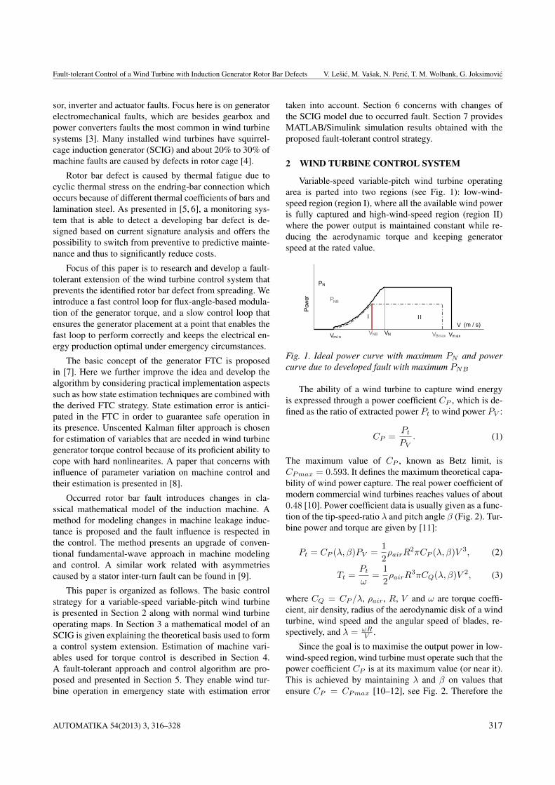
To avoid thermal stress of the defected rotor bar, curr-ents flowing through it should be less than currents flow-ing through the healthy ones. The magnitude of currents inrotor bar is sinusoidal and it is determined by the machinemagnetic flux. Speed at which the flux rotates along the ro-tor circumference is the generator slip speed defined with(10). Flux position with respect to the rotor is denotedwith θ. The flux affects the damaged rotor bar only on asmall part of its path as it moves along the circumference,whereas this path part is denoted with ∆θ = θ2 − θ1, seeFig. 6. Our primary goal is to reduce the electrical andthermal stress reflected through currents and correspond-ing generator torque in that angle span to the maximum
Rotor flux linkage angle (rad)
Gen
erat
or to
rque
(N
m)
Δθ
Tg_nonf
Tgf
toff t1 t2 ton τπ
(π)(θoff) (θ1) (θ2) (θon)
Tg1(t) Tg2(t)
Fig. 6. Torque modulation due to a fault condition. Inbrackets are angles attained at denoted time instant.
allowed safety value Tgf . The value Tgf is determinedbased on fault identification through machine fault mon-itoring and characterisation techniques, together with fluxangles θ1 and θ2 [5]. Related topic, focused on stator wind-ing inter-turn short circuit faults and periodically modu-lated stator flux is proposed in [18] and [19].
Torque is therefore modulated based on the machineflux angular position with respect to the damaged part asshown in Fig. 6. When the flux in angle θ approaches theangle span ∆θ, the torque is reduced to the maximum allo-wed value Tgf defined with a fault condition. After the fluxpasses it, the torque is restored to the right selected valueTg_nonf . The value Tg_nonf is determined such that the av-erage machine torque is maintained on the optimum level,taking into account the machine constraints. Procedure isthen periodically executed, with period equal π (or τπ intime domain), since the flux influences the faulty part withits north and south pole in each turn.
Using the described FOC algorithm with decouplingprocedure the generator is modelled as first-order lag sys-tem, as mentioned in Section 3. Torque transients fromFig. 6 are therefore defined as exponential functions, de-crease and increase respectively:
Tg1(t) = e−tτ (Tg_nonf − T1) + T1, (44)
Tg2(t) = T2 − e−tτ (T2 − Tgf ) . (45)
Slip speed of the generator is defined as
ωsl (Tg (t)) =dθ
dt, (46)
from which the angle is obtained:
θ(t)− θ(0) =
t∫
0
ωsl (Tg (t)) dt =
t∫
0
kTg (t) dt. (47)
Desired Tgf is reached with transient (44) at certaintime t1 and desired Tg_nonf is reached with transient (45)
AUTOMATIKA 54(2013) 3, 316–328 321
Fault-tolerant Control of a Wind Turbine with Induction Generator Rotor Bar Defects V. Lešic, M. Vašak, N. Peric, T. M. Wolbank, G. Joksimovic
at certain time ton:
Tgf = e−t1−toff
τ (Tg_nonf − T1) + T1, (48)
Tg_nonf = T2 − e−ton−t2
τ (T2 − Tgf ) . (49)
The angle span which has passed during the torque re-duction determines the angle θoff at which the transitionhas to start in order to reach the torque Tgf at angle θ1 dueto the finite bandwidth of the torque control loop. In thesame way torque restoration transient determines the angleθon at which the torque Tg_nonf is fully restored. Finally,θoff is derived from (18), (47) and (48):
θoff = θ1 − kτ (Tg_nonf − Tgf − T1ln a) , (50)
where ln a = lnTgf−T1
Tg_nonf−T1. In the same way, θon is ob-
tained as:
θon = θ2 + kτ (Tgf − Tg_nonf − T2ln b) , (51)
where ln b = lnT2−Tg_nonfT2−Tgf .
If the torque value Tg_nonf can be restored at some an-gle then the following relation holds:
θon − θoff 6 π. (52)
Putting (50) and (51) into (52), the following is obtainedfor condition (52):
−kτ (T1 ln a+ T2 ln b) 6 π −∆θ. (53)
Because of large inertia of the whole drivetrain, gen-erator and blade system, described torque oscillations (re-duction and restoration) are barely noticeable on the speedtransient, such that the wind turbine shaft perceives themean torque value:
Tav =1
τπ
τπ∫
0
Tgdt. (54)
Mean value of the generator torque from Fig. 6 is thengiven by:
Tav =π − 2kτ (T1 ln a+ T2 ln b)
kτπ, (55)
with
τπ =π −∆θ + kτ (T1 ln a+ T2 ln b)
kTg_nonf−
−τ (ln a+ ln b) +∆θ
kTgf. (56)
By applying torque (and corresponding q-current) refer-ences T1 and T2 from (18), (19), it is ensured that the gen-erator spends the least possible time in reduced torque area.
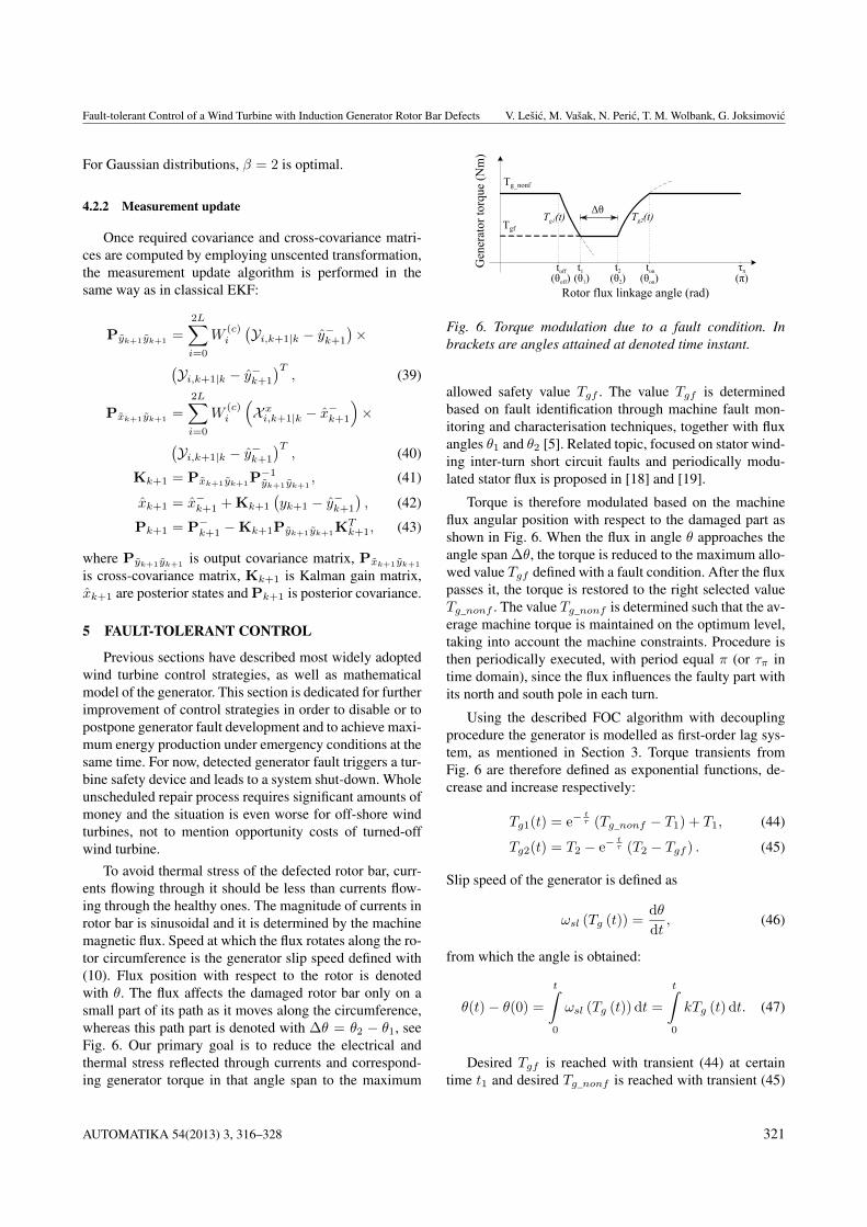
Equation (52) (or (53)) is not satisfied if the speed ωgis large enough (or if there is a large rotor path under faultinfluence). In that case the torque modulation is given withFig. 7 and peak torque T ∗g is attained at angle θ∗:
θ2 − π + kτ(Tgf − T ∗g − T2 ln b∗
)=
= θ1 − kτ(T ∗g − Tgf − T1 ln a∗
), (57)
where ln a∗ = lnTgf−T1
T∗g−T1and ln b∗ = ln
T2−T∗gT2−Tgf . Values
T ∗g and θ∗ can be obtained from:
kτ (T1 ln a∗ + T2 ln b∗) = ∆θ − π, (58)
θ∗ = θ1 − kτ(T ∗g − Tgf − T1ln a∗
). (59)
Gen
erat
or to
rque
(N
m)
Δθ
Rotor flux linkage angle (rad)
Tg*
Tgf
t* t1 t2 τπ
(π)(θ*) (θ1 ) (θ2 )*
Tg1(t)Tg2(t)
Fig. 7. Torque modulation due to a fault condition whenTg_nonf cannot be restored
Mean value of the generator torque from Fig. 7 (i.e. incase when (52) is not satisfied) is now given by
Tav =π − kτ (T1 ln a∗ + T2 ln b∗)
kτ∗π, (60)
with
τ∗π = −τ (ln a∗ + ln b∗) +∆θ
kTgf. (61)
Concludingly, if (53) is fulfilled, the resulting averagetorque is given with (55); if not, then the resulting aver-age torque is given with (60). On the boundary, i.e. forequality in (52) or (53), both (55) and (60) give the sametorque Tav , such that Tav(ωg) is continuous. The maxi-mum available torque Tg_nonf is the nominal generatortorque Tgn. Replacing Tg_nonf in (55) with the nominalgenerator torque Tgn gives the maximum available averagetorque under fault characterised with ∆θ and Tgf . Fig. 8shows an exemplary graph of available speed-torque pointsunder machine fault, where the upper limit is based on re-lations (53), (55) and (60) with Tg_nonf = Tgn. Dashedarea denotes all available average generator torque valuesthat can be achieved for certain generator speed.
From Fig. 8 it follows that up to the speed ωg1 it is po-ssible to control the wind turbine in the faulty case without
322 AUTOMATIKA 54(2013) 3, 316–328

Fault-tolerant Control of a Wind Turbine with Induction Generator Rotor Bar Defects V. Lešic, M. Vašak, N. Peric, T. M. Wolbank, G. Joksimovic
0 10 20 300
50
100
150
200
250Tgn
Tgf
Tav
Tgopt
ωg1
Speed (rpm)
Ge
ne
rato
r to
rqu
e (
kNm
) Healthy machine
Faulty machine
ωgn
Fig. 8. Available torque-speed generator operating pointsunder fault condition (shaded area). Full line is the achiev-able part of the wind turbine torque-speed curve underfaulty condition. Dash-dot line is the healthy machinecurve.
sacrificing power production. However, from that speedonwards it is necessary to use blades pitching in order tolimit the aerodynamic torque and to keep the power pro-duction below optimal such that fault spreading is sup-pressed. The speed control loop is modified such that in-stead of reference ωn the reference ω1 (in case of gear-box, ω1 = ωg1/ns) is selected. This activates pitch con-trol once the right edge of the feasible-under-fault optimaltorque characteristics is reached. The interventions in cla-ssical wind turbine control that ensure fault-tolerant con-trol are given in Fig. 9. Algorithms of the slow and the fastfault-tolerant control loop are given in the sequel. The fastloop is executed at each discrete time step, while the slowloop is performed once after every torque modulation pe-riod τπ .
Algorithm 1 Fault-tolerant control algorithm, slow loop
I. If T′gref ≤ Tgf , disable the fast loop and pass T
′gref
to the torque controller;
II. Compute Tg_nonf from (18), (19), (55) and (56)such that Tav(ωg) = T
′gref ; if Tg_nonf > Tgn, set
Tg_nonf = Tgn;
III. If (53) is fulfilled set θstart = θoff mod π andθend = θon else compute θ∗ from (59) and setθstart = θ∗ mod π, θend = θ2 and Tg_nonf = T2;
IV. Compute ωg1 as a speed coordinate of the intersec-tion point of Tav(ωg) and of the normal wind tur-bine torque controller characteristics, compute ω1 =ωg1/ns and set ωref = ω1.
Algorithm 2 Fault-tolerant control algorithm, fast loop
I. On the positive edge of logical conditions:
• θ > θstart set Tgref = T1,
• θ > θ1 set Tgref = Tgf ,
• θ > θ2 set Tgref = T2,
• θ > θend set Tgref = Tg_nonf .
a)
b)
FASTloop
SLOWloop
Fault detection and characterization
Tgref'
ωg
Tg_nonfTgref
TgfTgf θ1,θ2
θ
ωref
θstart
θend
T ,1 T2
TORQUEcontroller
GENERATOR & INVERTER
WIND
FAULT-TOLERANT control
ωref
ω
ω
β
Tg
ω
Tgref'
βref PITCH servo& controller
SPEEDcontroller
ωg
Tgref
θ
+-
Fig. 9. a) Control system of wind turbine with fault-tolerantcontrol strategy. b) Enlarged fault-tolerant control block.
5.1 UncertaintiesConsidering practical aspects of the algorithm imple-
mentation, a look-up table with Tg_nonf values can beused. Exponential torque transients can be approximatedwith straight lines for lower computational efforts as in [7].The real generator stator current measurements used forUKF correction procedure are noisy and the model usedfor estimation may deviate from the real generator system.Proposed fault-tolerant control algorithm is based on theaccurate information about machine magnetizing flux po-sition θ. Therefore, if θ is not correct, the torque is notreduced appropriately on the faulty part ∆θ and rotor-bardefect tends to spread further on.
To overcome the problem, faulty part ∆θ can be re-dundantly extended to ensure the proper torque reductionin the faulty machine section, making the FTC algorithmrobust on the error of flux position estimate. For that pur-pose we propose to include the flux position uncertaintyobtained from the estimation algorithm and state covari-ance matrix in θoff and θon calculations procedure. Faultypart ∆θ is extended by ±3σθ, where σθ is a square root of
AUTOMATIKA 54(2013) 3, 316–328 323

Fault-tolerant Control of a Wind Turbine with Induction Generator Rotor Bar Defects V. Lešic, M. Vašak, N. Peric, T. M. Wolbank, G. Joksimovic
the variance of machine flux position estimate θ extractedfrom the covariance matrix in (43). Probability that the trueflux position is within the presumed interval is:
p(θ ∈
[θ − 3σθ
], θ ∈
[θ + 3σθ
])= 99.73%. (62)
Another feature of the presented FTC algorithm is thattorque reduction at point θoff always starts at fixed timestep dictated by the sample time Ts. Therefore, it may missthe intended angle of θoff and begin at some point θoff +∆θTs . Depending on the sample time value this feature canhave a noticeable effect as well. Following from (46), ∆θTsis calculated as:
∆θTs = ωslTs = kTg_nonfTs. (63)
In the same manner, uncertainty of the fault detectionalgorithm can also be taken into consideration, formed as avariance σθ1 . All of described uncertainties are included inθoff and θon calculations with corrected values of θc1 andθc2:
θc1 = θ1 − 3σθ −∆θTs − 3σθ1 , (64)θc2 = θ2 + 3σθ + ∆θTs + 3σθ2 . (65)
That way, equations (50) and (51) with θc1 and θc2 remainunchanged.
6 CONTROL OF AN INDUCTION MACHINEWITH ROTOR ASYMMETRIES
In Section 3 a widely-adopted and well-tested RFOCalgorithm is described. It is based on so-called fundamentalwave machine model approach, which assumes ideal andsinusoidal distribution of magnetizing flux in the machineair-gap. It provides very good results and satisfying perfor-mance of the machine but neglects inherent asymmetriesdue to machine physics and geometry.
Because of occurred rotor bar defect, newly formedasymmetries are introduced inside machine rotor phases.They are reflected on the system performance in terms ofvibrations, as well as current and torque oscillations. Thediagnostics method for locating and characterisation of therotor bar defect proposed in [5, 6] is based on observationof this newly arisen system performance.
This section is dedicated for further improvement ofsystem performance and smooth operation of the slightlyasymmetric generator. Rotor bar defect causes very smallchange in resistanceRr and inductanceLr of the whole ro-tor cage, but has a noticeable impact on the leakage induc-tance Ll. In order to respect asymmetries in machine con-trol we propose an extension of the previously describedRFOC algorithm based on the variable leakage inductanceobservation.
For symmetric machine the leakage inductance is thesame for all phases and so far the Ll was implied to bea constant parameter. Due to occurred asymmetry in themachine, the leakage inductance is no longer the same forall phases and can be represented with a complex valuedenoted with Ll,t. It is composed of a scalar offset valueLoffset and a complex value Lmod. The offset value rep-resents the symmetric part while complex value includesinduced asymmetry with its magnitude and spatial direc-tion. More about this approach can be found in [5, 6]. Incommon (d, q) reference frame leakage inductance Ll,t isrepresented as:
Ll,t = Loffset + Lmod, Lmod = Lmod · ej2γ . (66)
The angle γ = ωslt + ϕ corresponds to the current loca-tion of the rotor bar defect with respect to the magnetizingflux. The frequency is doubled due to effects of both northand south magnetic field poles per single flux revolutionperiod. Both Lmod and γ are provided from the fault mon-itoring and characterisation technique.
The leakage inductance can be represented with:
Ll,t = Lld + j · Llq, (67)
where Lld = Loffset + Lmod cos(2γ), and Llq =Lmod sin(2γ).
By putting it into stator and rotor voltage equations (6)and (7) and by performing linear transformations of equal-ities, the following relations are obtained:
usd = kaisd + Ladisddt
+LlqLld
Rsisq −LlqLld
usq−
− ωeLaisq +
(LaTr− LsTr
)imr + ωe
LlqLld
Lsimr,
(68)
usq = Rsisq + Ladisqdt−(LlqLld
Rs +LlqLld
LsTr
)isd+
+LlqLld
usd + ωeLaisd +LlqLld
LsTrimr−
− ωe(La − Ls)imr, (69)
where ka = (Rs−LaTr
+LsTr
) andLa =(Lld +
L2lq
Lld
). In the
same way as in symmetric FOC, the decoupling methodis applied. By introducing correction voltages ∆usd and∆usq , fully decoupled relations are derived:
usd + ∆usd = kaisd + Ladisddt
, (70)
usq + ∆usq = Rsisq + Ladisqdt
, (71)
324 AUTOMATIKA 54(2013) 3, 316–328
Fault-tolerant Control of a Wind Turbine with Induction Generator Rotor Bar Defects V. Lešic, M. Vašak, N. Peric, T. M. Wolbank, G. Joksimovic
where
∆usd =LlqLld
usq −LlqLld
Rsisq + ωeLaisq−
−(LaTr− LsTr
)imr − ωe
LlqLld
Lsimr, (72)
∆usq = −LlqLld
usd +
(LlqLld
Rs +LlqLld
LsTr
)isd−
− ωeLaisd −LlqLld
LsTrimr + ωe(La − Ls)imr.
(73)
Equations (68)-(73) represent the mathematical modelof an asymmetric induction machine. With complex leak-age inductance from (66) and (67), influence of the ro-tor bar defect is respected in the machine control. WithLld = Loffset = Ll and Llq = 0 above relations arevalid for symmetric machine and obtain the same form asin (6)-(15).
In the same manner, PI controller parameters are cho-sen with integral time constants TIda = La/ka for d-current, TIqa = La/Rs for q-current. With index ’a’ con-troller parameters in case of detected asymmetry are de-noted. PI controller gain Kra is selected with respect todesired transient velocity and inverter constraints. Controlsystem block scheme remains the same as in Fig. 4. Theway of detecting the true value of transient leakage in-ductance Ll,t under asymmetric machine conditions deter-mines how much is the system performance improved withthe new FOC algorithm.
7 SIMULATION RESULTS
This section provides simulation results for a 700 kWMATLAB/Simulink variable-speed variable-pitch windturbine model with a two-pole 5.5 kW SCIG scaled tomatch the torque of 700 kW machine. Generator param-eters are: Ls = Lr = 0.112 H, Lm = 0.11 H, Rs =0.3304 Ω, Rr = 0.2334 Ω and PI controller gain isKr = 1. Turbine parameters are: CPmax = 0.4745,R = 25 m, λopt = 7.4, ωn = 29 rpm, Ttn = 230.5 kNmwith gearbox ratio ns = 105.77. Maximum voltage sup-plied to one phase is Umax = 2
3Udc = 467 V. Fault is sim-ulated between flux angles θ1 = π
2 and θ2 = π2 + π
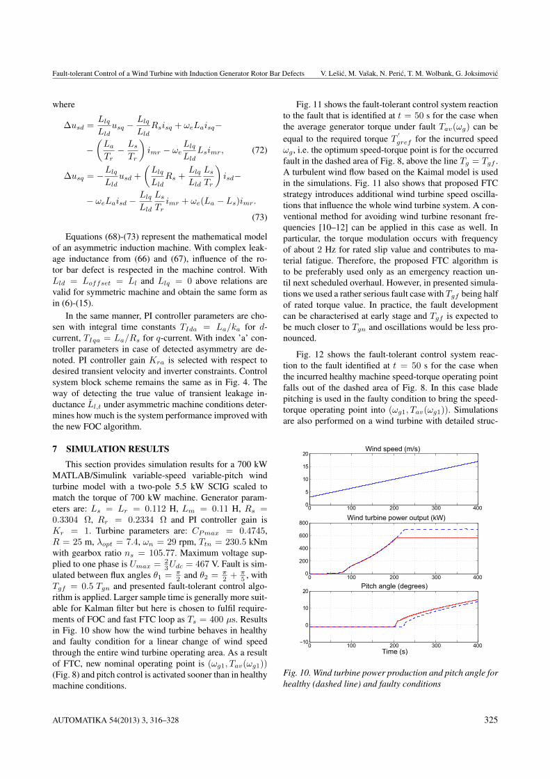
5 , withTgf = 0.5 Tgn and presented fault-tolerant control algo-rithm is applied. Larger sample time is generally more suit-able for Kalman filter but here is chosen to fulfil require-ments of FOC and fast FTC loop as Ts = 400 µs. Resultsin Fig. 10 show how the wind turbine behaves in healthyand faulty condition for a linear change of wind speedthrough the entire wind turbine operating area. As a resultof FTC, new nominal operating point is (ωg1, Tav(ωg1))(Fig. 8) and pitch control is activated sooner than in healthymachine conditions.
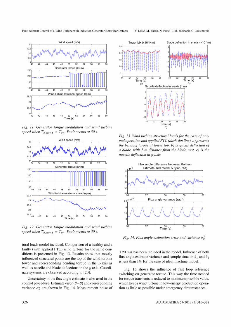
Fig. 11 shows the fault-tolerant control system reactionto the fault that is identified at t = 50 s for the case whenthe average generator torque under fault Tav(ωg) can beequal to the required torque T
′gref for the incurred speed
ωg , i.e. the optimum speed-torque point is for the occurredfault in the dashed area of Fig. 8, above the line Tg = Tgf .A turbulent wind flow based on the Kaimal model is usedin the simulations. Fig. 11 also shows that proposed FTCstrategy introduces additional wind turbine speed oscilla-tions that influence the whole wind turbine system. A con-ventional method for avoiding wind turbine resonant fre-quencies [10–12] can be applied in this case as well. Inparticular, the torque modulation occurs with frequencyof about 2 Hz for rated slip value and contributes to ma-terial fatigue. Therefore, the proposed FTC algorithm isto be preferably used only as an emergency reaction un-til next scheduled overhaul. However, in presented simula-tions we used a rather serious fault case with Tgf being halfof rated torque value. In practice, the fault developmentcan be characterised at early stage and Tgf is expected tobe much closer to Tgn and oscillations would be less pro-nounced.
Fig. 12 shows the fault-tolerant control system reac-tion to the fault identified at t = 50 s for the case whenthe incurred healthy machine speed-torque operating pointfalls out of the dashed area of Fig. 8. In this case bladepitching is used in the faulty condition to bring the speed-torque operating point into (ωg1, Tav(ωg1)). Simulationsare also performed on a wind turbine with detailed struc-
0 100 200 300 4000
5
10
15
20
0
200
400
600
800
−10
0
10
20
Wind speed (m/s)
Wind turbine power output (kW)
Pitch angle (degrees)
Time (s)
0 100 200 300 400
0 100 200 300 400
Fig. 10. Wind turbine power production and pitch angle forhealthy (dashed line) and faulty conditions
AUTOMATIKA 54(2013) 3, 316–328 325
Fault-tolerant Control of a Wind Turbine with Induction Generator Rotor Bar Defects V. Lešic, M. Vašak, N. Peric, T. M. Wolbank, G. Joksimovic
40 42 44 46 48 50 52 54 56 58 609
9.5
10
10.5
11
100
150
200
250
27
27.5
28
28.5
Wind speed (m/s)
Generator torque (kNm)
Wind turbine rotational speed (rpm)
Time (s)
40 42 44 46 48 50 52 54 56 58 60
40 42 44 46 48 50 52 54 56 58 60
Fig. 11. Generator torque modulation and wind turbinespeed when Tg_nonf < Tgn. Fault occurs at 50 s.
11
11.5
12
12.5
13
27.5
28
28.5
29
29.5
Wind speed (m/s)
Generator torque (kNm)
Wind turbine rotational speed (rpm)
Time (s)
100
150
200
250
40 42 44 46 48 50 52 54 56 58 60
40 42 44 46 48 50 52 54 56 58 60
40 42 44 46 48 50 52 54 56 58 60
Fig. 12. Generator torque modulation and wind turbinespeed when Tg_nonf = Tgn. Fault occurs at 50 s.
tural loads model included. Comparison of a healthy and afaulty (with applied FTC) wind turbine for the same con-ditions is presented in Fig. 13. Results show that mostlyinfluenced structural points are the top of the wind turbinetower and corresponding bending torque in the x-axis aswell as nacelle and blade deflections in the y axis. Coordi-nate systems are observed according to [20].
Uncertainty of the flux angle estimate is also used in thecontrol procedure. Estimate error (θ−θ) and correspondingvariance σ2
θ are shown in Fig. 14. Measurement noise of
2.6
Time (s)
Tower Mx ( 105 Nm)x
Time (s)
Nacelle deflection in y-axis (mm)
8
Time (s)
Blade deflection in y-axis ( 10-4 m)x
2.2
1.8
1.4
1
6
4
2
0
-2
30 32 34 36 38 40 30 32 34 36 38 40
30 32 34 36 38 40
0
-4
-8
-12
-16
a) b)
c)
Fig. 13. Wind turbine structural loads for the case of nor-mal operation and applied FTC (dash-dot line). a) presentsthe bending torque at tower top, b) is y-axis deflection ofa blade, with 1 m distance from the blade root, c) is thenacelle deflection in y-axis.
56 57 58 59 60−4
−2
0
2
4x 10⁻⁵
3
3.5
4
4.5x 10⁻¹¹
Flux angle difference between Kalman estimate and model output (rad)
Flux angle variance (rad2)
Time (s)56 57 58 59 60
Fig. 14. Flux angle estimation error and variance σ2θ
±20 mA has been included in the model. Influence of bothflux angle estimate variance and sample time on θ1 and θ2is less than 1% for the case of ideal machine model.
Fig. 15 shows the influence of fast loop referenceswitching on generator torque. This way the time neededfor torque transients is reduced to minimum possible value,which keeps wind turbine in low-energy production opera-tion as little as possible under emergency circumstances.
326 AUTOMATIKA 54(2013) 3, 316–328

Fault-tolerant Control of a Wind Turbine with Induction Generator Rotor Bar Defects V. Lešic, M. Vašak, N. Peric, T. M. Wolbank, G. Joksimovic
55 56 57 58 59 60−1000
−500
0
Time (s)
Generator torque (kNm)
Tgref
56 56.1 56.2 56.3 56.4
100
150
200
250
56.5
Fig. 15. Generator torque transients
8 CONCLUSION
This paper introduces a fault-tolerant control schemefor variable-speed variable-pitch wind turbines with asquirrel-cage induction generator. We focus on genera-tor rotor bar defect that can be characterised at earlystage of development. Presented method is used as an au-tonomous control reaction to diagnosed fault in order toavoid wind turbine shut-down. Results show that simpleextension of the conventional wind turbine control struc-ture prevents the fault propagation while power deliveryunder fault is deteriorated as less as possible comparedto healthy machine conditions. State estimation errors andfault-introduced asymmetries are respected in operation aswell.
ACKNOWLEDGEMENT
The research leading to these results has received fund-ing from the European Community’s Seventh FrameworkProgramme under grant agreement no 285939 (ACROSS)and from the European Commission and the Republic ofCroatia under grant FP7-SEE-ERA.net PLUS ERA 80/01,project MONGS - Monitoring of Wind Turbine GeneratorSystems.
REFERENCES
[1] Renewable Energy Policy Network for the 21st Century(REN21), "Renewables 2012," Global status report, 2012.
[2] S. Pourmohammad, A. Fekih, "Fault-tolerant Control ofWind Turbine Systems - A Review," Proc. of the 2011. IEEEGreen Technologies Conference (IEEE-Green), April 2011.
[3] Z. Daneshi-Far, G. A. Capolino, H. Henao, "Review of Fail-ures and Condition Monitoring in Wind Turbine Genera-tors," XIX International Conference on Electrical Machines- ICEM 2010, Sept. 2010.
[4] A. H. Bonnet and C. Yung, “Increased Efficiency Versus In-creased Reliability,” IEEE Industry Applications Magazine,vol.14, no.1, pp. 29-36, 2008.
[5] G. Stojicic, P. Nussbaumer, G. Joksimovic, M. Vašak,N. Peric and T. M. Wolbank, "Precise Separation of Inher-ent Induction Machine Asymmetries from Rotor Bar FaultIndicator," 8th IEEE International Symposium on Diagnos-tics for Electrical Machines, Power Electronics & Drives,SDEMPED, pp. 9-15, Sept. 2011.
[6] G. Stojicic, M. Samonig, P. Nussbaumer, G. Joksimovic,M. Vašak, N. Peric and T. M. Wolbank, "Monitoring of RotorBar Faults in Induction Generators with Full-size Inverter,"Proceedings of the 14th European Conference on PowerElectronics and Applications, EPE, pp. 1-8, Aug.-Sept. 2011.
[7] V. Lešic, M. Vašak, N. Peric, T. M. Wolbank and G. Joksi-movic, "Fault-Tolerant Control of a Blade-pitch Wind Tur-bine With Inverter-fed Generator," 20th IEEE InternationalSymposium on Industrial Electronics, ISIE, pp. 2097-2102,June 2011.
[8] V. Lešic, M. Vašak, G. Stojicic, N. Peric, G. Joksimovic andT. M. Wolbank, "State and Parameter Estimation for Field-oriented Control of Induction Machine Based on UnscentedKalman Filter," International Symposium on Power Electron-ics, Electrical Drives, Automation and Motion, SPEEDAM,June 2012.
[9] V. Lešic, M. Vašak, M. Gulin, N. Peric, G. Joksimovicand T. M. Wolbank, "Field-oriented Control of an Induc-tion Machine with Winding Asymmetries," 15th Interna-tional Power Electronics and Motion Control Conference,EPE-PEMC 2012 ECCE Europe, pp. LS7b-1.2-1–7, Sept.2012.
[10] M. Jelavic, “Wind Turbine Control for Structural DynamicLoads Reduction (in Croatian),” PhD Thesis, Faculty of Elec-trical Engineering and Computing, University of Zagreb,2009.
[11] F. D. Bianchi, H. De Battista and R. J. Mantz, Wind TurbineControl Systems - Principles, Modelling and Gain Schedul-ing Design, London: Springer, ISBN 1-84628-492-9, 2007.
[12] T. Burton, D. Sharpe, N. Jenkins and E. Bossanyi, Wind En-ergy Handbook, London: John Wiley & Sons, ISBN 0-471-48997-2, 2001.
[13] M. P. Kazmierkowski, F. Blaabjerg and R. Krishnan, Con-trol in Power Electronics - Selected Problems, San Diego,California: Academic Press, An imprint of Elsevier Science,ISBN 0-12-402772-5, 2002.
[14] S. J. Julier and J. K. Uhlmann, A General Method for Ap-proximating Nonlinear Transformations of Probability Dis-tributions, Technical report, Dept. of Engineering Science,University of Oxford, Nov. 1996.
[15] E. A. Wan and R. van der Merwe, "The Unscented KalmanFilter" in Kalman Filtering and Neural Networks. S. Haykin,Ed. New York: John Wiley & Sons, ISBN 0-471-36998-5,2001.
AUTOMATIKA 54(2013) 3, 316–328 327
Fault-tolerant Control of a Wind Turbine with Induction Generator Rotor Bar Defects V. Lešic, M. Vašak, N. Peric, T. M. Wolbank, G. Joksimovic
[16] M. Vašak, M. Baotic, I. Petrovic and N. Peric, "ElectronicThrottle State Estimation and Hybrid Theory Based OptimalControl", Proceedings of the IEEE International Symposiumon Industrial Electronics ISIE 2004, pp. 323-328, May 2004.
[17] M. Doumiati, A. Victorino, A. Charara and D. Lech-ner, "Onboard Real-Time Estimation of Vehicle LateralTire–Road Forces and Sideslip Angle", IEEE/ASME Trans-actions on Mechatronics, vol. 16, no. 4, pp. 601-614, 2010.
[18] V. Lešic, M. Vašak, N. Peric, G. Joksimovic and T. M.Wolbank, "Fault-tolerant Control of a Wind Turbine witha Squirrel-cage Induction Generator and Stator Inter-turnFaults", The 12th International Workshop on Advanced Mo-tion Control, AMC, 6 pages, March 2012.
Vinko Lešic received his master degree in electri-cal engineering and information technology fromUniversity of Zagreb Faculty of Electrical Engi-neering and Computing (UNIZG-FER) in 2010.Currently, he is with the Department of Con-trol and Computer Engineering at UNIZG-FERwhere he is pursuing his PhD degree. His re-search interests are in the area of control theorywith application to advanced control of electricaldrives and wind turbine generators.
Mario Vašak is an Assistant Professor at theDepartment of Control and Computer Engineer-ing of University of Zagreb Faculty of Electri-cal Engineering and Computing (UNIZG-FER).He received his PhD degree in Electrical Engi-neering from UNIZG-FER in 2007. He works inthe areas of predictive/robust/fault-tolerant con-trol and computational geometry applied to them,in the following application domains: renew-able energy systems, water management systems,
energy-efficient buildings, energy-efficient railway transportation and au-tomotive systems. On behalf of UNIZG-FER he led an FP7-SEE-ERA.netPLUS research project MONGS on generator-fault-tolerant control inwind turbines, and currently he is UNIZG-FER leader of the FP7-STREPUrbanWater that deals with fresh water supply system management inurban environments. He published over 50 papers in journals and confer-ence proceedings.
Nedjeljko Peric received the B.Sc., M.Sc. andPh.D. degrees in Electrical Engineering from theUniversity of Zagreb Faculty of Electrical Engi-neering and Computing (UNIZG-FER) in 1973,1980, and 1989, respectively. From 1973 to 1993he worked at the Institute of Electrical Engi-neering of the Koncar Corporation, Croatia, asan R&D engineer, Head of the Positioning Sys-tems Department, and Manager of the Automa-tion Section. In 1993 he joined the Department
of Control and Computer Engineering at UNIZG-FER as an associateprofessor. He was appointed as a full professor in 1997 and since 2010he serves as UNIZG-FER dean. His current research interests are in thefields of process identification and advanced control techniques. In peri-ods 1992-1998 and 2000-2011 he served as the Chairman of KoREMA,the Croatian Society for Communications, Computing, Electronics, Mea-surements and Control. He is also a member of several international pro-fessional associations. Professor Peric is a Fellow of Croatian Academyof Engineering.
[19] V. Lešic, M. Vašak, N. Peric, G. Joksimovic and T. M. Wol-bank, "Fault-tolerant Control of a Wind Turbine with Gener-ator Stator Inter-turn Faults", Automatika, vol. 54, no. 1, pp.89-102, 2013.
[20] Germanischer Lloyd Industrial Services GmbH, "Guidelinefor the Certification of Wind Turbines", 2010.
Thomas M. Wolbank received the doctoral de-gree and the Habilitation from Vienna Univer-sity of Technology, Vienna, Austria, in 1996and 2004, respectively. Currently, he is with theDepartment of Energy Systems and ElectricalDrives, Vienna University of Technology, Vi-enna, Austria. He has co-authored some 100 pa-pers in refereed journals and international con-ferences. His research interests include saliency-based sensorless control of AC drives, dynamicproperties and condition monitoring of inverter-
fed machines, transient electrical behavior of AC machines, motor drivesand their components as well as controlling them by the use of intelligentcontrol algorithms.
Gojko M. Joksimovic received PhD degree andthe Full Professor degree from University ofMontenegro, Montenegro, in 2000 and 2011, re-spectively. His main research areas include ana-lysis of electrical machines, condition monitoringof electrical machines, and power electronics andcontrol. He is the author of a few books and morethan 50 papers published in leading internationalscientific journals and international conferences.
AUTHORS’ ADDRESSESVinko Lešic, M.Sc.Asst. Prof. Mario Vašak, Ph.D.Prof. Nedjeljko Peric, Ph.D.Department of Control and Computer Engineering,Faculty of Electrical Engineering and Computing,University of Zagreb,Unska 3, HR-10000, Zagreb, Croatiaemail: vinko.lesic,mario.vasak,[email protected]. Thomas M. Wolbank, Ph.D.Institute of Energy Systems and Electrical Drives,Faculty of Electrical Engineering and InformationTechnology,Vienna University of Technology,Gusshausstrasse 25/370-2, AT-1040, Vienna, Austriaemail: [email protected]. Gojko M. Joksimovic, Ph.D.Faculty of Electrical Engineering,University of Montenegro,Džordža Vašingtona bb, ME-81000, Podgorica, Montenegroemail: [email protected]
Received: 2012-01-31Accepted: 2012-11-20
328 AUTOMATIKA 54(2013) 3, 316–328