Automatic Transaxle (07.01) · Automatic Transmission (07.01) Transmission (07.00) 7-1-4 Workshop...
7
Automatic Transmission (07.01) Transmission (07.00) 7-1-2 Workshop Manual Issue 7, September 2011 Transmission (07.00) Automatic Transaxle (07.01) Description The ZF 6HP26 automatic gearbox has the following features: All hydraulic functions are directed by electronic solenoids for control: The ZF 6HP26 Automatic Transmission is a six-speed electronically controlled transmission that has the parts that follow: • A Mechatronik module (Transmission Control Module (TCM) and a main control valve body assembly) • A torque converter • One solenoid valve and six pressure regulators. To select the gears, transmission oil flow is used to operate the different internal clutches The TCM operates the electrical components and gives control of the shift pressure for the gear selection. This gives better control of the torque converter slip. If there is a system malfunction, the TCM has Failure Mode Effect Management (FMEM) to make sure that the transmission gives the maximum available performance. At the same time it makes sure there is the minimum possible effect on driver, passenger or vehicle safety. If there is a total loss of control or electrical power, the transmission keeps the basic functions of Park, Reverse, Neutral and Drive. The hydraulic system will also keep 3 rd or 5 th gear if these are selected at the time of the failure. The transmission also has turbine and output shaft speed sensors, an internal P, R, N, D selector position sensor, and a transmission oil temperature sensor. The TCM also needs information from the shift selector module to show if the driver has selected manual gears. The TCM talks to other electronic control modules through the Controller Area Network (CAN). To obey the CARB OBDII legislation, the TCM does transmission fault-finding. This monitors all components that can effect vehicle emissions. There are also more fault-find functions to make sure that that all malfunctions can be repaired quickly by maintenance staff. A torque converter supplies the engine power to the transmission. The torque converter has a lock-up clutch. There are six forward gears and one reverse gear. A single planetary gear set is followed by a double planetary gear set to give the six forward gears. This is named a ìLepelletierî type gear set. Cooling The Auto transmission has an external cooling circuit that prevents overheating of the transmission oil. A pump is installed in the gearbox that pumps the transmission oil around the radiator and back to the transmission. It operates on changes in the engine speed. A wax and poppet type thermostat is installed close to the gearbox inlet and outlet to control the oil temperature. The range of operation is 74° C - 88° C. Mechatronik module The Mechatronik module is installed in the sump of the automatic gearbox. It has electrical actuators and sensors and also hydraulic valves which operate with the TCM to change the changes. The parts are installed so that they can be replaced while the automatic gearbox is still installed in the vehicle. (Refer to ’Automatic Control System (07.05)’, page 7-5-1) • Six forward speeds and One reverse • A torque converter with an integral converter lock-up clutch • Electronic shift and pressure controls • A single planetary gear set • A double planetary gear set • Two fixed multi-disc brakes • Three multi-plate clutches • Engagement feel • Shift feel • Shift scheduling • Modulated torque converter clutch (TCC) applications • Engine braking utilizing the coast clutch
Transcript of Automatic Transaxle (07.01) · Automatic Transmission (07.01) Transmission (07.00) 7-1-4 Workshop...
Automatic Transmission (07.01)Transmission (07.00)
7-1-2 Workshop Manual Issue 7, September 2011
Transmission (07.00)
Automatic Transaxle (07.01)DescriptionThe ZF 6HP26 automatic gearbox has the following features:
All hydraulic functions are directed by electronic solenoids for control:
The ZF 6HP26 Automatic Transmission is a six-speed electronically controlled transmission that has the parts that follow:
• A Mechatronik module (Transmission Control Module (TCM) and a main control valve body assembly)
• A torque converter• One solenoid valve and six pressure regulators.
To select the gears, transmission oil flow is used to operate the different internal clutches
The TCM operates the electrical components and gives control of the shift pressure for the gear selection. This gives better control of the torque converter slip.
If there is a system malfunction, the TCM has Failure Mode Effect Management (FMEM) to make sure that the transmission gives the maximum available performance. At the same time it makes sure there is the minimum possible effect on driver, passenger or vehicle safety.
If there is a total loss of control or electrical power, the transmission keeps the basic functions of Park, Reverse, Neutral and Drive.
The hydraulic system will also keep 3rd or 5th gear if these are selected at the time of the failure.
The transmission also has turbine and output shaft speed sensors, an internal P, R, N, D selector position sensor, and a transmission oil temperature sensor.
The TCM also needs information from the shift selector module to show if the driver has selected manual gears.
The TCM talks to other electronic control modules through the Controller Area Network (CAN).
To obey the CARB OBDII legislation, the TCM does
transmission fault-finding.
This monitors all components that can effect vehicle emissions.
There are also more fault-find functions to make sure that that all malfunctions can be repaired quickly by maintenance staff.
A torque converter supplies the engine power to the transmission. The torque converter has a lock-up clutch.
There are six forward gears and one reverse gear. A single planetary gear set is followed by a double planetary gear set to give the six forward gears. This is named a ìLepelletierî type gear set.
CoolingThe Auto transmission has an external cooling circuit that prevents overheating of the transmission oil.A pump is installed in the gearbox that pumps the transmission oil around the radiator and back to the transmission. It operates on changes in the engine speed.A wax and poppet type thermostat is installed close to the gearbox inlet and outlet to control the oil temperature. The range of operation is 74° C - 88° C.
Mechatronik moduleThe Mechatronik module is installed in the sump of the automatic gearbox.It has electrical actuators and sensors and also hydraulic valves which operate with the TCM to change the changes.The parts are installed so that they can be replaced while the automatic gearbox is still installed in the vehicle.(Refer to ’Automatic Control System (07.05)’, page 7-5-1)
• Six forward speeds and One reverse
• A torque converter with an integral converter lock-up clutch
• Electronic shift and pressure controls
• A single planetary gear set
• A double planetary gear set
• Two fixed multi-disc brakes
• Three multi-plate clutches
• Engagement feel• Shift feel• Shift scheduling
• Modulated torque converter clutch (TCC) applications
• Engine braking utilizing the coast clutch

Automatic Transmission (07.01)Transmission (07.00)
Issue 7, September 2011 Workshop Manual 7-1-3
SpecificationsGearbox
1
2
3
4
5
67
8
9
10
1. Hydraulic Module 2. Position Switch 3. Adaptor4. Electronic Module 5. Turbine Speed Sensor 6. Suction Port7. Output Speed Sensor 8. Solenoid Valve9. Temperature Sensor 10.Discharge Port
Type6 speed ZF 6HP26 automatic transmission and torque converter
WeightComplete with transmission oil - 89 kg (196.25 lbs) approx.
Control SystemElectrohydraulic (Mechatronik)Controlled on-load shiftsVarious shift programs available
Torque ConverterControlled-slip lock-up clutch in gears 1 - 6 and reverse.
Transmission oilShell ATF Transmission Qty.Coolant system Qty.
10 Ltr (17.06 pt. / 10.57 US qts.)1.6 Ltr (2.8 pt. / 1.7 US qts.)
The ZF 6HP26 automatic transmission is ‘filled for life’ at manufacturer and will not normally need to be serviced.
Gear Ratios1st 2nd 3rd 4th 5th 6th4.17:1 2.34:1 1.52:1 1.14:1 0.87:1 0.69:1Reverse3.40:1
Maximum Towing Distance150 km (93 miles) at a maximum speed of 70 km/h (43 mph)
Torque FiguresDescription Nm. lb. / ft.Transaxle to Mounting Brackets 20-30 15-22.5Mechatronics Unit 8 6Sump 7-9 5.5-7Gearbox to Differential Adaptor Plate 52-75 38.5-55.5Subframe cross-member 85 63
Transmission oil

Automatic Transmission (07.01)Transmission (07.00)
7-1-4 Workshop Manual Issue 7, September 2011
Differential
MaintenanceTransmission Oil Check / FillThe ZF 6 HP26 automatic transmission is ‘filled for life’ when it is made and it will not usually need to be serviced. If there is an oil leak from the transmission cooling system, you must repaire the leak and then do the steps that follow to add oil to the transmission:
Before you do a check of the transmission oil level, make sure that:• The car is on a horizontal ramp• The rear wheels do not move for a minimum of 2 minutes
before you start the oil level check and during the process, for example: operate the hand brake
• The transmission sump temperature is between 30° C and 50° C (86° F and 122° F) when you open the filling plug and while you do a check of the oil level
• You have engaged the Reverse and Drive gear positions for a minimum of 3 seconds with rear wheels braked before you do a check
• The TCM is not in “limp-home” mode.
1. Remove the rear under tray.
2. Remove the right exhaust pipe.3. Operate the engine at between 600 and 750 rpm.4. Put an applicable container under the fill hole to collect
oil that may spill from the opening.5. Remove the fill plug (1) (at the rear-right side of the
transmission) immediately after you start the engine (see Figure below).
6. Add transmission oil to the transmission (Refer to ’Specifications’, page 7-1-3), until transmission oil drains out of the bore. Do not add more oil.
7. Wait until the oil that flows from the transmission slows to a dribble for at least one minute or the oil has reached 50° C (122° F).
8. Install the fill plug and make sure that the sump temperature has not gone higher than 50° C (122° F).
9. Install the right exhaust pipe.10. Install the rear under tray.
TypeGraziano AM803D
WeightComplete with differential oil - 47.25 kg (104 lbs) approx
Differential oilShell ‘Transaxle’ oil 75W/90Gearbox Qty.Coolant system Qty.
1.7 Ltr (3 pt. / 1.8 US qts.)0.7 Ltr (1.2 pt. / 0.7 US qts.)
Torque FiguresDescription Nm. lb. / ft.Differential Housing Cover (bolts smeared with Loctite 242)
35 26
Output Shaft Cover 10 7.5Sump PlugFill Plug
4949
36.536.5
End Cover 30 22.5
WARNINGOBEY ALL TRANSMISSION OIL MANUFACTURERS SAFETY INSTRUCTIONS WHEN YOU DRAIN AND
REFILL THE AUTOMATIC TRANSMISSION.
WARNINGWHEN THE ENGINE OPERATES, MAKE SURE THAT AN EXHAUST EXTRACTOR SYSTEM IS ATTACHED TO THE
EXHAUST SYSTEM.
WARNINGDO NOT BREATHE EXHAUST FUMES. EXHAUST
FUMES CONTAIN CARBON MONOXIDE. CARBON MONOXIDE IS A DANGEROUS GAS THAT IS
COLOURLESS AND ODOURLESS. IT CAN CAUSE UNCONSCIOUSNESS AND CAN KILL.
1
Automatic Transmission (07.01)Transmission (07.00)
Issue 7, September 2011 Workshop Manual 7-1-5
Automatic Transaxle
Remove1. Remove the rear subframe with the transaxle (Refer to
’Rear Subframe’, page 2-1-5).2. Remove the six bolts and the three washer tabs from
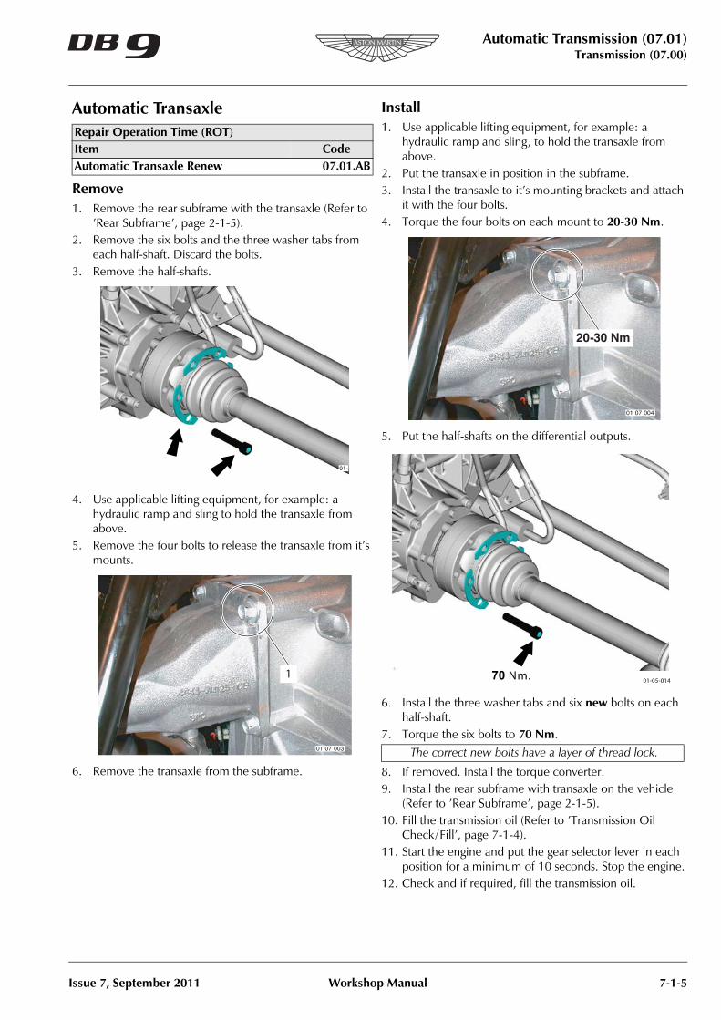
each half-shaft. Discard the bolts.3. Remove the half-shafts.
4. Use applicable lifting equipment, for example: a hydraulic ramp and sling to hold the transaxle from above.
5. Remove the four bolts to release the transaxle from it’s mounts.
6. Remove the transaxle from the subframe.
Install1. Use applicable lifting equipment, for example: a
hydraulic ramp and sling, to hold the transaxle from above.
2. Put the transaxle in position in the subframe. 3. Install the transaxle to it’s mounting brackets and attach
it with the four bolts.4. Torque the four bolts on each mount to 20-30 Nm.
5. Put the half-shafts on the differential outputs.
6. Install the three washer tabs and six new bolts on each half-shaft.
7. Torque the six bolts to 70 Nm.
8. If removed. Install the torque converter.9. Install the rear subframe with transaxle on the vehicle
(Refer to ’Rear Subframe’, page 2-1-5).10. Fill the transmission oil (Refer to ’Transmission Oil
Check / Fill’, page 7-1-4).11. Start the engine and put the gear selector lever in each
position for a minimum of 10 seconds. Stop the engine.12. Check and if required, fill the transmission oil.
Repair Operation Time (ROT)Item CodeAutomatic Transaxle Renew 07.01.AB
01-0
The correct new bolts have a layer of thread lock.
01-05-01470 Nm.
Automatic Transmission (07.01)Transmission (07.00)
7-1-6 Workshop Manual Issue 7, September 2011
Mechatronik Unit
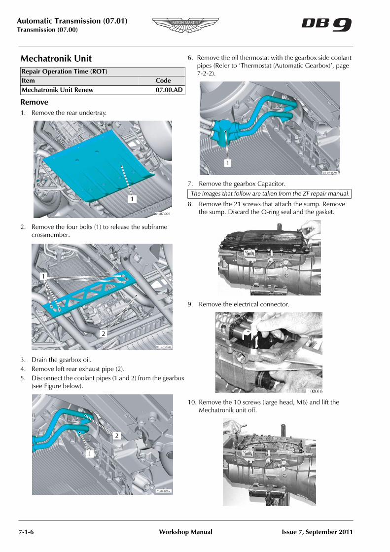
Remove1. Remove the rear undertray.
2. Remove the four bolts (1) to release the subframe crossmember.
3. Drain the gearbox oil.4. Remove left rear exhaust pipe (2).5. Disconnect the coolant pipes (1 and 2) from the gearbox
(see Figure below).
6. Remove the oil thermostat with the gearbox side coolant pipes (Refer to ’Thermostat (Automatic Gearbox)’, page 7-2-2).
7. Remove the gearbox Capacitor.
8. Remove the 21 screws that attach the sump. Remove the sump. Discard the O-ring seal and the gasket.
9. Remove the electrical connector.
10. Remove the 10 screws (large head, M6) and lift the Mechatronik unit off.
Repair Operation Time (ROT)Item CodeMechatronik Unit Renew 07.00.AD
1The images that follow are taken from the ZF repair manual.

Automatic Transmission (07.01)Transmission (07.00)
Issue 7, September 2011 Workshop Manual 7-1-7
11.Remove and discard the seals for the the Mechatronik unit.
Install1. Install new seals for the Mechatronik unit.
2. Push the Mechatronik unit into position with your hand.3. Install the 10 screws and torque them, in the sequence
shown below, to 8 Nm.
4. Push in the new electrical connector socket into position with the Mechatronik unit screw plug attached. Attach it with the retaining clip.
5. Install a new O-ring seal onto the stub-pipe of the transmission oil filter.
6. Push a new seal into the sump.
7. Install the gearbox capacitor.8. Install the sump and attach it with the 21 screws. Torque
the screws to 7-9 Nm.
9. Install a new drain plug and torque plug to 9 Nm.10. Install the oil thermostat with gearbox side coolant
pipes.

Automatic Transmission (07.01)Transmission (07.00)
7-1-8 Workshop Manual Issue 7, September 2011
11. Connect the coolant pipes (1 and 2) to the gearbox. Torque the bolt to 20-25 Nm (see Figure below).
12. Install the left rear exhaust pipe (2).13. Put the subframe crossmember in position and attach it
with the four bolts (1).14. Torque the four bolts (1) to 85 Nm.
15. Fill the gearbox oil (Refer to ’Transmission Oil Check / Fill’, page 7-1-4).
16. Start the engine and put the gear selector lever in each position for at least 10 seconds.
17. Stop the engine.18. If necessary, fill the gearbox oil.19. Install the rear undertray.
Differential Output Seal (Left)
If you need to replace both left and right seals, change the left seal first.
Remove1. Disconnect the vehicle battery.2. Raise the vehicle and make it safe.3. Remove the left road wheel and the road wheel-arch
liner.4. Remove the rear undertray.
5. Remove the service brake and the handbrake calipers (Refer to ’Brake Caliper (Front and Rear)’, page 6-3-2).
6. Remove the vertical link (Refer to ’Rear Suspension (04.02)’, page 4-2-1).
7. Drain the differential oil. 8. Remove the six bolts and the three washer tabs to
release the half-shaft.
9. Remove the four bolts that attach the output shaft cover.
10. Attach a slide hammer and remove the output shaft cover complete with the output shaft and the bearing. Discard the O-ring.
11. Remove the circlip and remove the bearing.Repair Operation Time (ROT)Item CodeDifferential Output Seal (Left) Renew 07.00.AC
When you replace the right seal, the left output shaft will hold the differential unit in position.
The oil pump impeller ring can come out with the output shaft. Make sure that the oil pump impeller ring is in the
correct position at installation.
01-05-011