Automatic Temp Controllerfaculty.petra.ac.id/resmana/private/circuit-cellar/...perature controller...
7
www.circuitcellar.com CIRCUIT CELLAR ® Issue 154 May 2003 1 traditional bar- becue typically involves cooking tough cuts of meat (e.g., pork ribs, pork shoulder, and beef brisket) over a wood or charcoal fire at a low temperature (200° to 250°F). The meat is cooked for long periods of time until it’s tender (e.g., 5 to 6 h for ribs and 10 to 20 h for brisket or pork shoulder). Usually, steel offset cook- ers, modified 55-gallon drums, and even in-ground pits are used. Another barbecue tradition requires someone to be present for the 5 to 20 h that the meat is cooking. This person must add fuel so the fire does- n’t go out and regulate the cooking temperature. Although modern tech- nology can’t shorten barbecue-cooking times, it can eliminate the need for someone to be present to maintain the cooking temperature. CERAMIC COOKERS Photo 1 shows a different kind of cooker. The cooker’s thick ceramic walls do such a good job of insulating that a single load of lump charcoal fuel can maintain barbecue-cooking temperatures for more than 24 h. This neatly solves the problem of having to add fuel during a cooking session, but there’s still the issue of temperature regulation. The firebox is at the bot- tom of the cooker, and the tempera- ture is adjusted using the lower and upper draft openings. Additional air moving through the cooker produces a bigger fire and higher temperature. After it’s set for a given temperature, a ceramic cooker does a remarkable job of maintaining that temperature. However, if internal or external condi- tions shift too much (e.g., changes in the weather or wind, or ash buildup in the firebox), the draft settings must be adjusted in order to keep the tempera- ture from changing. To have true hands-off temperature control, you need a closed-loop process control sys- tem. In such a system, the actual cooker temperature is monitored and used to adjust the airflow to maintain the desired temperature. PROJECT GOALS The original goal for this project was to implement a simple closed-loop tem- perature controller using an 8-bit micro- processor. Modeled after a kitchen oven, I wanted the controller to have a knob for setting the desired temperature. A temperature probe would monitor the ceramic cooker’s actual temperature, and the controller would adjust the airflow to keep the desired and actual temperatures as close as possible. a Most chefs would argue that barbecuing is more art than sci- ence. Nevertheless, John introduced ATmega8-based tech- nology to the proce- dure. The result? An automatic tempera- ture controller that eliminates the need for constant vigilance when slow cooking. John Moyer FEATURE ARTICLE Automatic Temp Controller Enable G V+ D MOSFET switch S V+ V+ G V+ D G V+ V+ V OUT V OUT V OUT V OUT Figure 1a—With no thermocouple connected, a test voltage applied to the op-amp produces a maximum output voltage. b—The low impedance of a connected thermocouple drastically reduces the test voltage, pro- ducing a much lower output voltage. a) b) Data Logger for Slow Cooker Circuit Cellar, the Magazine for Computer Applications. Reprinted by permission. For subscription information, call (860) 875-2199, or www.circuitcellar.com. Entire contents copyright ©2001 Circuit Cellar Inc. All rights reserved.
Transcript of Automatic Temp Controllerfaculty.petra.ac.id/resmana/private/circuit-cellar/...perature controller...
www.circuitcellar.com CIRCUIT CELLAR® Issue 154 May 2003 1
traditional bar-becue typically
involves cookingtough cuts of meat (e.g.,
pork ribs, pork shoulder, and beefbrisket) over a wood or charcoal fire ata low temperature (200° to 250°F). Themeat is cooked for long periods oftime until it’s tender (e.g., 5 to 6 h forribs and 10 to 20 h for brisket or porkshoulder). Usually, steel offset cook-ers, modified 55-gallon drums, andeven in-ground pits are used.
Another barbecue tradition requiressomeone to be present for the 5 to20 h that the meat is cooking. Thisperson must add fuel so the fire does-n’t go out and regulate the cookingtemperature. Although modern tech-nology can’t shorten barbecue-cookingtimes, it can eliminate the need forsomeone to be present to maintain thecooking temperature.
CERAMIC COOKERSPhoto 1 shows a different kind of
cooker. The cooker’s thick ceramicwalls do such a good job of insulatingthat a single load of lump charcoalfuel can maintain barbecue-cookingtemperatures for more than 24 h. Thisneatly solves the problem of having toadd fuel during a cooking session, but
there’s still the issue of temperatureregulation. The firebox is at the bot-tom of the cooker, and the tempera-ture is adjusted using the lower andupper draft openings. Additional airmoving through the cooker produces abigger fire and higher temperature.
After it’s set for a given temperature,a ceramic cooker does a remarkablejob of maintaining that temperature.However, if internal or external condi-tions shift too much (e.g., changes inthe weather or wind, or ash buildup inthe firebox), the draft settings must beadjusted in order to keep the tempera-ture from changing. To have truehands-off temperature control, youneed a closed-loop process control sys-tem. In such a system, the actualcooker temperature is monitored andused to adjust the airflow to maintainthe desired temperature.
PROJECT GOALSThe original goal for this project was
to implement a simple closed-loop tem-perature controller using an 8-bit micro-processor. Modeled after a kitchen oven,I wanted the controller to have a knobfor setting the desired temperature. Atemperature probe would monitor theceramic cooker’s actual temperature,and the controller would adjust theairflow to keep the desired and actualtemperatures as close as possible.
aMost chefs wouldargue that barbecuingis more art than sci-ence. Nevertheless,John introducedATmega8-based tech-nology to the proce-dure. The result? Anautomatic tempera-ture controller thateliminates the needfor constant vigilancewhen slow cooking.
John Moyer
FEATUREARTICLE
Automatic Temp Controller
EnableG
V+
D
MOSFET switch
S
V+
V+
G
V+
D
G
V+
V+
VOUTVOUT
VOUT VOUT
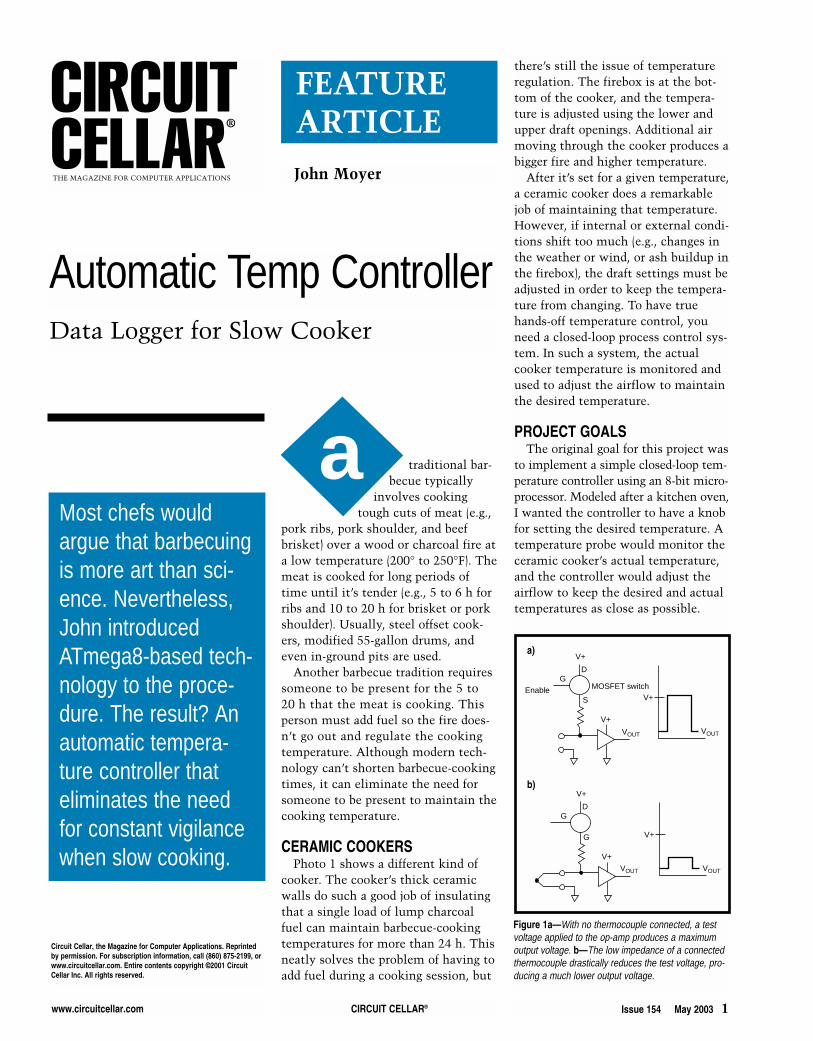
Figure 1a—With no thermocouple connected, a testvoltage applied to the op-amp produces a maximumoutput voltage. b—The low impedance of a connectedthermocouple drastically reduces the test voltage, pro-ducing a much lower output voltage.
a)
b)
Data Logger for Slow Cooker
Circuit Cellar, the Magazine for Computer Applications. Reprintedby permission. For subscription information, call (860) 875-2199, orwww.circuitcellar.com. Entire contents copyright ©2001 CircuitCellar Inc. All rights reserved.
2 Issue 154 May 2003 CIRCUIT CELLAR® www.circuitcellar.com
tion is heated, a voltage proportionalto the temperature can be measured atthe other end of the wires. Differenttypes of metals have been standard-ized, and their voltage-versus-temper-ature properties characterized. Thisproject uses a type-K thermocouple.
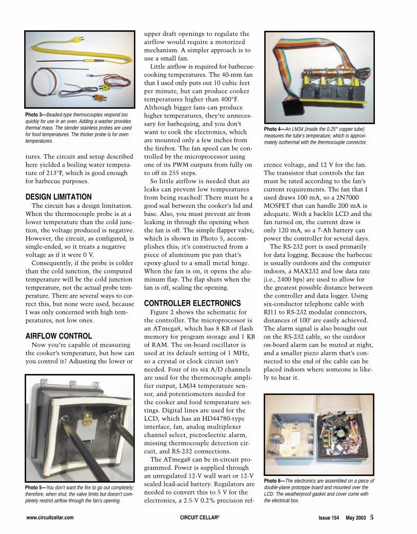
Generally, type-K can be used fortemperatures up to 2300°F, althoughthe insulating materials used in thelow-cost probes limit the upper tem-perature to approximately 500°F forTeflon and 900° for glass braid.Photo 3 shows typical thermocoupleconfigurations. Although thermocou-ples are simple, rugged, and inexpen-sive, they have some properties thatmust be accommodated.
Being microprocessor controlled, Ithought it would be easy to add otherfunctionality, such as additional probesto monitor the food temperature, andanother control to indicate the desiredfinal food temperature. An alarm couldring when the food reached a desiredtemperature or if an error conditionoccurred. An RS-232 port would allowcooker and food temperatures to belogged, either to a local computer orperhaps a web site for remote access.Photo 2 shows the front panel of myfinal controller implementation.
As for the control system’s accuracy,my intention was make it at least asgood as a kitchen oven. Temperaturetolerances only needed to be within
±5°, because barbequing is more of anart than a science. Temperature is justone factor to be consider when you’retrying to determine if the food isready to be taken off the fire.
TEMPERATURE ACQUISITIONTemperatures are measured by tak-
ing an analog measurement from atemperature probe. Converting it to adigital value using the micro’s A/Dconverter, and then converting theraw measurement to an actual tem-perature achieves this.
The temperature probe I used is athermocouple, which is constructedsimply by connecting two dissimilartypes of metal wire. When this junc-
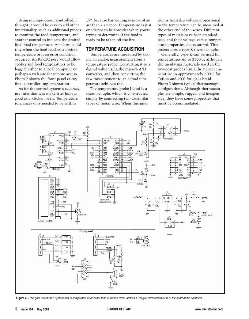
Figure 2—The goal is to build a system that is comparable to or better than a kitchen oven. Atmel’s ATmega8 microcontroller is at the heart of the controller.
www.circuitcellar.com CIRCUIT CELLAR® Issue 154 May 2003 3
THERMOCOUPLE PROPERTIES First, the output voltage of a type-K
thermocouple is only about 20 µV (i.e.,0.00002 V) per 1°F. This must be ampli-fied in order to use the microprocessor’sA/D converter, but most amplifiersaren’t suitable. General-purpose op-amps typically have input offset voltageerrors of 1 to 5 mV, which correspondsto a temperature error of hundreds ofdegrees! The precision op-amp usedinstead has a maximum offset voltageerror of only 5 µV, or less than a quar-ter-degree error. The amplifier circuit isconfigured for a gain of 111; therefore,by using a 2.5-V reference with the A/Dconverter, you can measure tempera-tures from 32° to roughly 1000°F withapproximately 1° resolution.
Of course, if you were to amplifythe thermocouple signal, you’d alsoamplify any noise signals in this nottoo carefully constructed circuit. Youcan minimize the effects of noise bytaking multiple (32 to 256) A/D read-ings and averaging them to produce asingle temperature measurement.
The second thermocouple problemis that output is nonlinear. You cannotperform a simple division to convertvoltage to temperature. This is easilydealt with by storing the type-K volt-age-to-temperature table in the con-troller software. [1] The 0° to 1000°Ftemperature range can be divided intoapproximately linear regions. You canuse linear interpolation to determine atemperature within a given region.
The final thermocouple problem isthat output is relative, not absolute.
The voltage at the probe end of thethermocouple where the two dissimi-lar wires connect is relative to thevoltage at the circuit end, where thethermocouple wires connect to thevoltage measurement circuit. If theprobe and circuit ends have the sametemperature, the measured voltagewill be zero. If the probe end is hot-ter, a positive voltage will be meas-ured. If it’s colder, a negative voltagewill be measured.
Therefore, in order to know theactual temperature at the probe end,you need to know the temperature ofthe circuit end. Historically, this wasaccomplished by keeping the circuitend in an ice bath so its temperatureremained 32°. Consequently, theconnection between the thermocou-ple and measuring circuit came to beknown as the “cold junction.” Theprocess of using the junction temper-ature to calculate the actual probetemperature is referred to as coldjunction compensation.
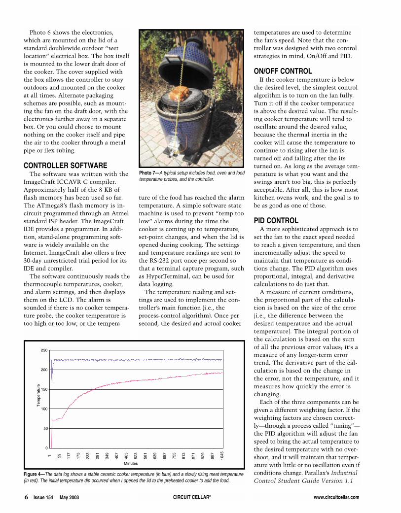
Instead of using ice, which is some-what impractical for a barbecue appli-cation, you can use an IC temperaturesensor to directly measure the actualtemperature of the cold junction. Forthis to work, the sensor and physicalconnection point where the thermo-couple wires meet the copper circuitwires must be the same temperature(i.e., isothermal). A difference in tem-perature will directly affect the accu-racy of the temperature measurement.One method, which seems to workacceptably well, is shown in Photo 4.
0
50
100
150
200
250
300
1
155
309
463
617
771
925
1079
1233
1387
1541
1695
1849
2003
2157
2311
2465
2619
2773
Seconds
Tem
pera
ture
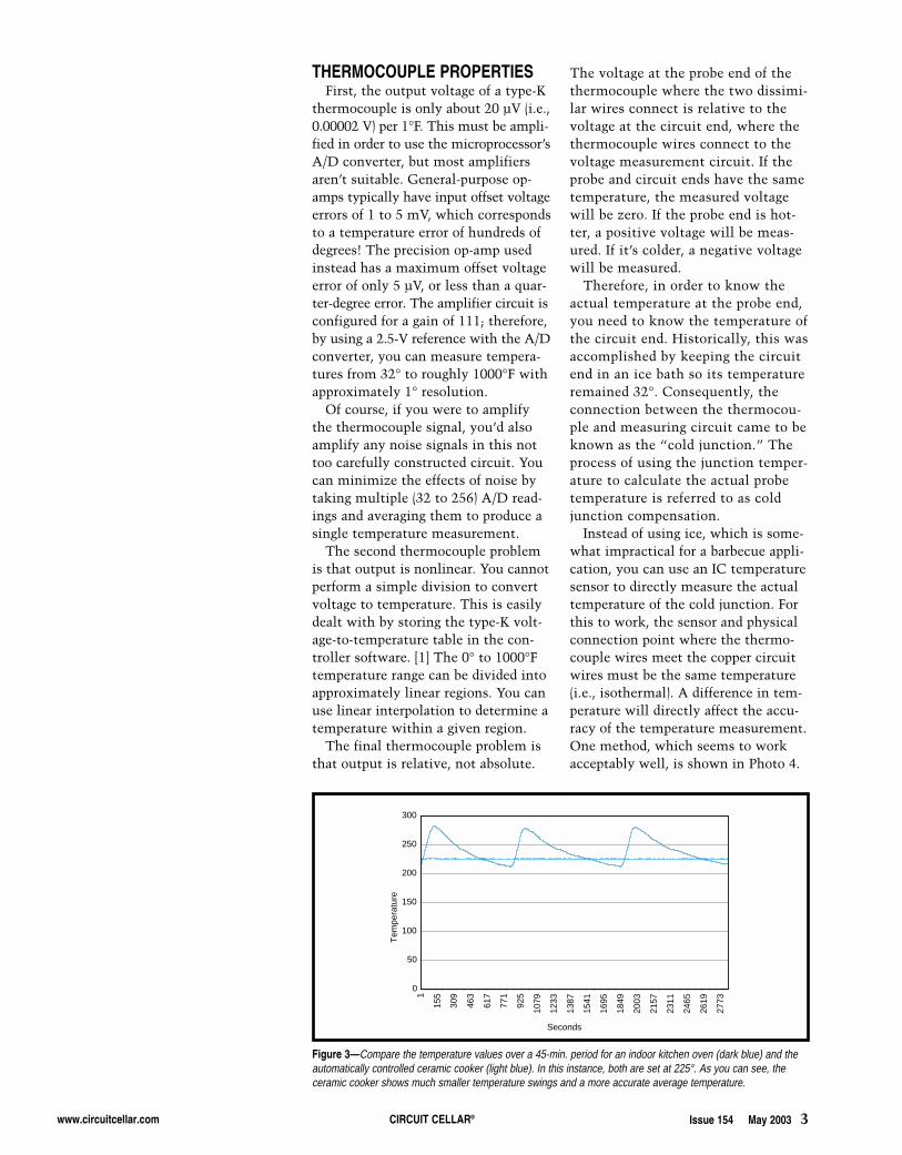
Figure 3—Compare the temperature values over a 45-min. period for an indoor kitchen oven (dark blue) and theautomatically controlled ceramic cooker (light blue). In this instance, both are set at 225°. As you can see, theceramic cooker shows much smaller temperature swings and a more accurate average temperature.
4 Issue 154 May 2003 CIRCUIT CELLAR® www.circuitcellar.com
MULTIPLE THERMOCOUPLESAfter you have the basic setup to
measure one channel, it’s easy to add ananalog multiplexer to select from one ofseveral channels. However, in order toprevent false alarms from the alarm cir-cuit, you need to know if a thermocou-ple is actually connected to a channel.The circuit shown in Figure 1 allowsthe microprocessor to determine this.
TEMP MEASUREMENTYou must complete several steps to
make a single temperature measure-ment. First, select the channel to beread by setting the analog multiplexerto one of the four thermocouples. Then,see if there is actually a thermocoupleconnected by turning on the missingthermocouple test voltage and takingan ADC measurement. Remember thata single measurement is actually theaverage of 32 to 256 readings.
If the result is the maximum A/Dvalue, then there is no thermocoupleconnected to that channel, so report atemperature value of zero. Otherwise,turn off the missing thermocouple testvoltage, and measure the actual ther-mocouple output.
Using the A/D reading, the amplifi-
er gain (111), and the A/D voltage ref-erence value (2.5 V), compute theactual thermocouple voltage. A 10-bitA/D reading will be in the 0- to 1023-Vrange, so the actual voltage is equal tothe following:
Next, take and average multipleA/D readings of the cold junction tem-perature sensor, and convert that volt-age to the cold junction temperature.Using the cold junction temperatureand the type-K voltage/temperaturetable, compute the type-K voltagethat’s equivalent to the cold junctiontemperature. Add the thermocouplevoltage to the cold junction voltage.Using the type-K table, convert thesummed thermocouple and cold junc-tion voltages to the actual thermocou-ple temperature.
MEASUREMENT ACCURACYThere are several sources for error in
this process, including the inherentinaccuracies of the thermocouple andcold-junction temperature sensor, howisothermal the cold junction and sen-sor really are, the accuracies of theA/D converter and voltage reference,and gain errors in the amplifier. Agood reality check is to test the tem-perature of boiling water, because212°F is actually within the range ofthe typical barbecue-cooking tempera-
A/D reading 2.5 111
××1024
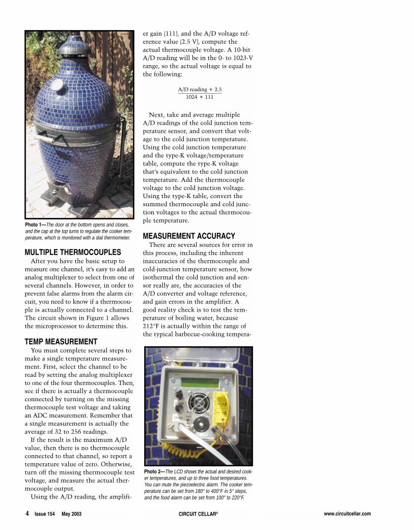
Photo 1—The door at the bottom opens and closes,and the cap at the top turns to regulate the cooker tem-perature, which is monitored with a dial thermometer.
Photo 2—The LCD shows the actual and desired cook-er temperatures, and up to three food temperatures.You can mute the piezoelectric alarm. The cooker tem-perature can be set from 180° to 400°F in 5° steps,and the food alarm can be set from 100° to 220°F.
www.circuitcellar.com CIRCUIT CELLAR® Issue 154 May 2003 5
upper draft openings to regulate theairflow would require a motorizedmechanism. A simpler approach is touse a small fan.
Little airflow is required for barbecue-cooking temperatures. The 40-mm fanthat I used only puts out 10 cubic feetper minute, but can produce cookertemperatures higher than 400°F.Although bigger fans can producehigher temperatures, they’re unneces-sary for barbequing, and you don’twant to cook the electronics, whichare mounted only a few inches fromthe firebox. The fan speed can be con-trolled by the microprocessor usingone of its PWM outputs from fully onto off in 255 steps.
So little airflow is needed that airleaks can prevent low temperaturesfrom being reached! There must be agood seal between the cooker’s lid andbase. Also, you must prevent air fromleaking in through the opening whenthe fan is off. The simple flapper valve,which is shown in Photo 5, accom-plishes this; it’s constructed from apiece of aluminum pie pan that’sepoxy-glued to a small metal hinge.When the fan is on, it opens the alu-minum flap. The flap shuts when thefan is off, sealing the opening.
CONTROLLER ELECTRONICSFigure 2 shows the schematic for
the controller. The microprocessor isan ATmega8, which has 8 KB of flashmemory for program storage and 1 KBof RAM. The on-board oscillator isused at its default setting of 1 MHz,so a crystal or clock circuit isn’tneeded. Four of its six A/D channelsare used for the thermocouple ampli-fier output, LM34 temperature sen-sor, and potentiometers needed forthe cooker and food temperature set-tings. Digital lines are used for theLCD, which has an HD44780-typeinterface, fan, analog multiplexerchannel select, piezoelectric alarm,missing thermocouple detection cir-cuit, and RS-232 connections.
The ATmega8 can be in-circuit pro-grammed. Power is supplied throughan unregulated 12-V wall wart or 12-Vsealed lead-acid battery. Regulators areneeded to convert this to 5 V for theelectronics, a 2.5-V 0.2% precision ref-
erence voltage, and 12 V for the fan.The transistor that controls the fanmust be rated according to the fan’scurrent requirements. The fan that Iused draws 100 mA, so a 2N7000MOSFET that can handle 200 mA isadequate. With a backlit LCD and thefan turned on, the current draw isonly 120 mA, so a 7-Ah battery canpower the controller for several days.
The RS-232 port is used primarilyfor data logging. Because the barbecueis usually outdoors and the computerindoors, a MAX232 and low data rate(i.e., 2400 bps) are used to allow forthe greatest possible distance betweenthe controller and data logger. Usingsix-conductor telephone cable withRJ11 to RS-232 modular connectors,distances of 100′ are easily achieved.The alarm signal is also brought outon the RS-232 cable, so the outdooron-board alarm can be muted at night,and a smaller piezo alarm that’s con-nected to the end of the cable can beplaced indoors where someone is like-ly to hear it.
tures. The circuit and setup describedhere yielded a boiling water tempera-ture of 213°F, which is good enoughfor barbecue purposes.
DESIGN LIMITATIONThe circuit has a design limitation.
When the thermocouple probe is at alower temperature than the cold junc-tion, the voltage produced is negative.However, the circuit, as configured, issingle-ended, so it treats a negativevoltage as if it were 0 V.
Consequently, if the probe is colderthan the cold junction, the computedtemperature will be the cold junctiontemperature, not the actual probe tem-perature. There are several ways to cor-rect this, but none were used, becauseI was only concerned with high tem-peratures, not low ones.
AIRFLOW CONTROLNow you’re capable of measuring
the cooker’s temperature, but how canyou control it? Adjusting the lower or
Photo 6—The electronics are assembled on a piece ofdouble-plane prototype board and mounted over theLCD. The weatherproof gasket and cover come withthe electrical box.
Photo 5—You don’t want the fire to go out completely;therefore, when shut, the valve limits but doesn’t com-pletely restrict airflow through the fan’s opening.
Photo 4—An LM34 (inside the 0.25″ copper tube)measures the tube’s temperature, which is approxi-mately isothermal with the thermocouple connector.
Photo 3—Beaded-type thermocouples respond tooquickly for use in an oven. Adding a washer providesthermal mass. The slender stainless probes are usedfor food temperatures. The thicker probe is for oventemperatures.
6 Issue 154 May 2003 CIRCUIT CELLAR® www.circuitcellar.com
Photo 6 shows the electronics,which are mounted on the lid of astandard doublewide outdoor “wetlocation” electrical box. The box itselfis mounted to the lower draft door ofthe cooker. The cover supplied withthe box allows the controller to stayoutdoors and mounted on the cookerat all times. Alternate packagingschemes are possible, such as mount-ing the fan on the draft door, with theelectronics further away in a separatebox. Or you could choose to mountnothing on the cooker itself and pipethe air to the cooker through a metalpipe or flex tubing.
CONTROLLER SOFTWAREThe software was written with the
ImageCraft ICCAVR C compiler.Approximately half of the 8 KB offlash memory has been used so far.The ATmega8’s flash memory is in-circuit programmed through an Atmelstandard ISP header. The ImageCraftIDE provides a programmer. In addi-tion, stand-alone programming soft-ware is widely available on theInternet. ImageCraft also offers a free30-day unrestricted trial period for itsIDE and compiler.
The software continuously reads thethermocouple temperatures, cooker,and alarm settings, and then displaysthem on the LCD. The alarm issounded if there is no cooker tempera-ture probe, the cooker temperature istoo high or too low, or the tempera-
ture of the food has reached the alarmtemperature. A simple software statemachine is used to prevent “temp toolow” alarms during the time thecooker is coming up to temperature,set-point changes, and when the lid isopened during cooking. The settingsand temperature readings are sent tothe RS-232 port once per second sothat a terminal capture program, suchas HyperTerminal, can be used fordata logging.
The temperature reading and set-tings are used to implement the con-troller’s main function (i.e., theprocess-control algorithm). Once persecond, the desired and actual cooker
temperatures are used to determinethe fan’s speed. Note that the con-troller was designed with two controlstrategies in mind, On/Off and PID.
ON/OFF CONTROLIf the cooker temperature is below
the desired level, the simplest controlalgorithm is to turn on the fan fully.Turn it off if the cooker temperatureis above the desired value. The result-ing cooker temperature will tend tooscillate around the desired value,because the thermal inertia in thecooker will cause the temperature tocontinue to rising after the fan isturned off and falling after the itsturned on. As long as the average tem-perature is what you want and theswings aren’t too big, this is perfectlyacceptable. After all, this is how mostkitchen ovens work, and the goal is tobe as good as one of those.
PID CONTROLA more sophisticated approach is to
set the fan to the exact speed neededto reach a given temperature, and thenincrementally adjust the speed tomaintain that temperature as condi-tions change. The PID algorithm usesproportional, integral, and derivativecalculations to do just that.
A measure of current conditions,the proportional part of the calcula-tion is based on the size of the error(i.e., the difference between thedesired temperature and the actualtemperature). The integral portion ofthe calculation is based on the sumof all the previous error values; it’s ameasure of any longer-term errortrend. The derivative part of the cal-culation is based on the change inthe error, not the temperature, and itmeasures how quickly the error ischanging.
Each of the three components can begiven a different weighting factor. If theweighting factors are chosen correct-ly—through a process called “tuning”—the PID algorithm will adjust the fanspeed to bring the actual temperature tothe desired temperature with no over-shoot, and it will maintain that temper-ature with little or no oscillation even ifconditions change. Parallax’s IndustrialControl Student Guide Version 1.1
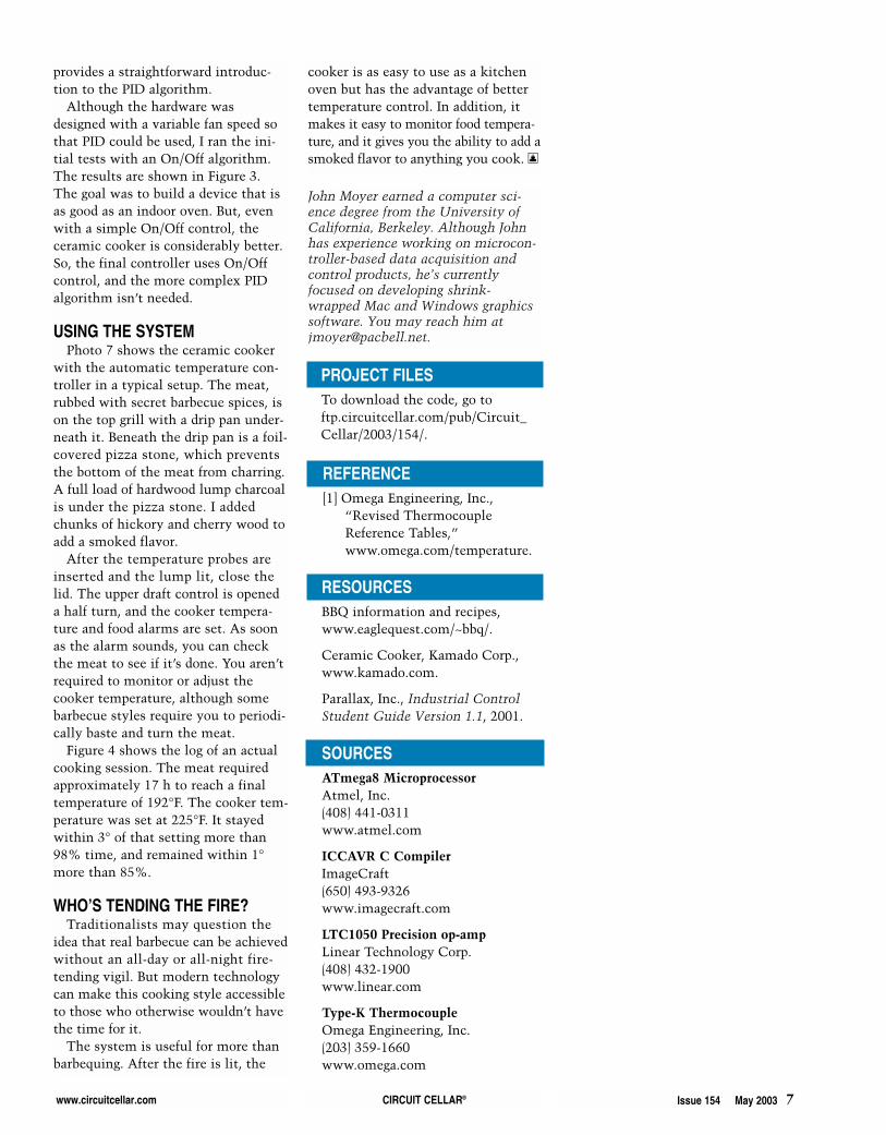
Figure 4—The data log shows a stable ceramic cooker temperature (in blue) and a slowly rising meat temperature(in red). The initial temperature dip occurred when I opened the lid to the preheated cooker to add the food.
Photo 7—A typical setup includes food, oven and foodtemperature probes, and the controller.
www.circuitcellar.com CIRCUIT CELLAR® Issue 154 May 2003 7
provides a straightforward introduc-tion to the PID algorithm.
Although the hardware wasdesigned with a variable fan speed sothat PID could be used, I ran the ini-tial tests with an On/Off algorithm.The results are shown in Figure 3.The goal was to build a device that isas good as an indoor oven. But, evenwith a simple On/Off control, theceramic cooker is considerably better.So, the final controller uses On/Offcontrol, and the more complex PIDalgorithm isn’t needed.
USING THE SYSTEM Photo 7 shows the ceramic cooker
with the automatic temperature con-troller in a typical setup. The meat,rubbed with secret barbecue spices, ison the top grill with a drip pan under-neath it. Beneath the drip pan is a foil-covered pizza stone, which preventsthe bottom of the meat from charring.A full load of hardwood lump charcoalis under the pizza stone. I addedchunks of hickory and cherry wood toadd a smoked flavor.
After the temperature probes areinserted and the lump lit, close thelid. The upper draft control is openeda half turn, and the cooker tempera-ture and food alarms are set. As soonas the alarm sounds, you can checkthe meat to see if it’s done. You aren’trequired to monitor or adjust thecooker temperature, although somebarbecue styles require you to periodi-cally baste and turn the meat.
Figure 4 shows the log of an actualcooking session. The meat requiredapproximately 17 h to reach a finaltemperature of 192°F. The cooker tem-perature was set at 225°F. It stayedwithin 3° of that setting more than98% time, and remained within 1°more than 85%.
WHO’S TENDING THE FIRE?Traditionalists may question the
idea that real barbecue can be achievedwithout an all-day or all-night fire-tending vigil. But modern technologycan make this cooking style accessibleto those who otherwise wouldn’t havethe time for it.
The system is useful for more thanbarbequing. After the fire is lit, the
cooker is as easy to use as a kitchenoven but has the advantage of bettertemperature control. In addition, itmakes it easy to monitor food tempera-ture, and it gives you the ability to add asmoked flavor to anything you cook. I
SOURCESATmega8 MicroprocessorAtmel, Inc.(408) 441-0311www.atmel.com
ICCAVR C CompilerImageCraft(650) 493-9326www.imagecraft.com
LTC1050 Precision op-ampLinear Technology Corp.(408) 432-1900www.linear.com
Type-K ThermocoupleOmega Engineering, Inc.(203) 359-1660www.omega.com
PROJECT FILESTo download the code, go toftp.circuitcellar.com/pub/Circuit_Cellar/2003/154/.
RESOURCESBBQ information and recipes,www.eaglequest.com/~bbq/.
Ceramic Cooker, Kamado Corp.,www.kamado.com.
Parallax, Inc., Industrial ControlStudent Guide Version 1.1, 2001.
REFERENCE[1] Omega Engineering, Inc.,
“Revised ThermocoupleReference Tables,”www.omega.com/temperature.
John Moyer earned a computer sci-ence degree from the University ofCalifornia, Berkeley. Although Johnhas experience working on microcon-troller-based data acquisition andcontrol products, he’s currentlyfocused on developing shrink-wrapped Mac and Windows graphicssoftware. You may reach him [email protected].