
Automatic plant watering system - · PDF filePage 3 of 14 Circuit diagram: Fig: Circuit...
14
Page 1 of 14 Automatic plant watering system
Transcript of Automatic plant watering system - · PDF filePage 3 of 14 Circuit diagram: Fig: Circuit...

Page 1 of 14
Automatic plant watering system

Page 2 of 14
Project Abstract:
Problem: 1) Wastage of water due to supply more than required.
2) Not watering plants whenever required.
Solution: 1) An electronic device that will water the plant automatically as on when required.
2) Sensors which will switch on LED to give reminder or will switch on electric pump to
water the plants.
Model: The circuit is designed to sense dryness of the soil and subsequently switch on the
electric pump to start the supply of water and switch off the pump whenever sufficient
water is supplied.
The Materials used are : Transistor 548, Resistor 1k, Variable resistor 47kΩ, Diode
1N4007, Relay 5v, LED, DC converter, Circuit board, Probes, AC water pump, Water
reservoir, etc.
Two probes of the circuit are to be inserted in the soil around plant.
Observations: The circuit works as follow.
Soil status Working of circuit
Dry Circuit is switched on and pump starts
Wet Circuit is switched off and pump stops
Further plan: Solar panel will be installed in the circuit to save electricity
Message:
Electronics is multipurpose tool, useful even to water plants.

Page 3 of 14
Circuit diagram:
Fig: Circuit diagram of plant watering system
Circuit working:
When the soil is dry then there would be high resistance which will allow the flow of current
and transistor T2 will get switch on, this will let the current flow towards the diode and thus
relay will get switch on. When the relay gets switched on, 230V current will be supplied to
water pump and water will be supplied to the plants. As soon as soil gets wet; two probes of
the circuit will conduct electricity due to presence of the ions in the soil and soon transistor T1
will get switch on due to low resistance between probes, thus switches off the pump and water
supply to be stopped. The circuit is also consists of a variable resistor through which sensitivity
of probes can be adjusted.

Page 4 of 14
PCB Layout:
(Do not stretch /change dimensions of this figure)
Fig: PCB Layout
Structural diagram:
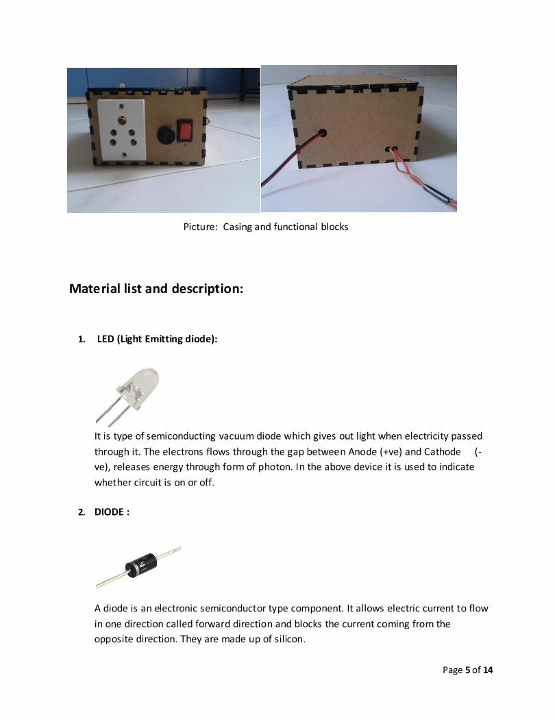
Page 5 of 14
Picture: Casing and functional blocks
Material list and description:
1. LED (Light Emitting diode):
It is type of semiconducting vacuum diode which gives out light when electricity passed
through it. The electrons flows through the gap between Anode (+ve) and Cathode (-
ve), releases energy through form of photon. In the above device it is used to indicate
whether circuit is on or off.
2. DIODE :
A diode is an electronic semiconductor type component. It allows electric current to flow
in one direction called forward direction and blocks the current coming from the
opposite direction. They are made up of silicon.

Page 6 of 14
3. VARIABLE RESISTOR (Potentiometer):
Variable resistor is type of three terminals resistor in which, resistance can be
set according to requirement. In the above device it is used to set sensitivity of
the probes.
4. CIRCUIT BOARD :
Circuit board is the plate on which electronic components are fixed. It consists of many
tiny holes in which components are soldered. It’s plating done with copper metal.

Page 7 of 14
5. RELAY :
Relay is type of switch which is activated when electric current passed through. It has
two poles A (+ve) and B (-ve). When electric current is passed through them an inbuilt
electromagnet is activated and the common pole and the other poles get connected and
circuit gets complete. In this circuit the common pole has one connection of AC pump
and other pole has connection of
AC input.
6. TRANSISTOR:
A transistor is a type of semi-conductor, it acts like an amplifier or like a switch. It has
three terminals i.e. collector, base and emitter. There are two types of transistors NPN ( -
ve to +ve) and PNP (+ve to –ve). In this circuit BC 548 transistor is used. BC548 is a NPN
bipolar junction transistor.
7. RESISTOR :
Page 8 of 14
A resistor is a electronic component which is used to reduce the current. There are
various types of resistors classified based on amount of voltage they resists.
There are a specific color bands which denotes the value of resistor. Resistance is
measured in ohm (Ω). In above circuit resistor of 1k Ω is used.
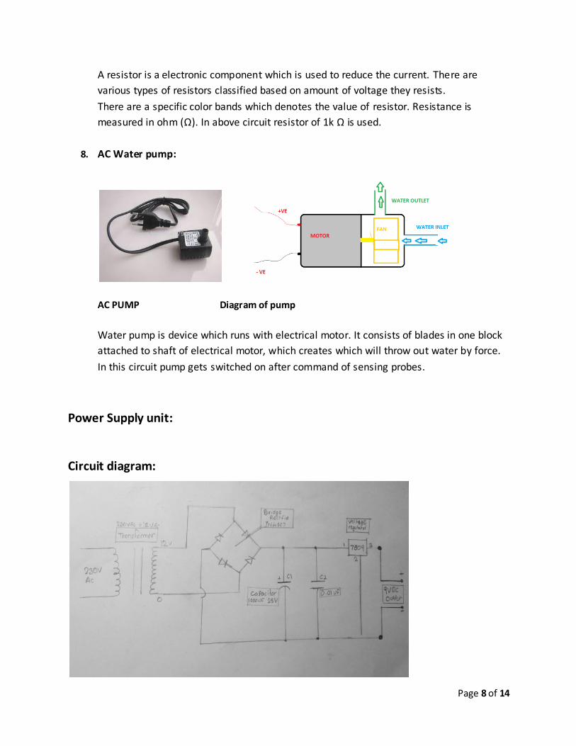
8. AC Water pump:
AC PUMP Diagram of pump
Water pump is device which runs with electrical motor. It consists of blades in one block
attached to shaft of electrical motor, which creates which will throw out water by force.
In this circuit pump gets switched on after command of sensing probes.
Power Supply unit:
Circuit diagram:

Page 9 of 14
Block diagram:
1. Transformer :
Transformer is an electrical device that transfers energy two or more circuits through
electromagnetic induction. A varying current in the transformers primary winding
creates a varying magnetic flux in the core and varying magnetic field impinging on the
secondary winding. This varying magnetic field at the secondary induces a varying
electromagnetic force or voltage in the secondary winding. Making use of Faraday’s law
in conjunction with high magnetic permeability core properties, transformers can thus
be designed to efficiently change AC from one voltage level to another within power
networks. In above circuit step down transformer is used to covert current of 230V to
12V.

Page 10 of 14
2. Rectifier :
A rectifier is an electrical device that converts alternating current (AC), which
periodically reverses direction, to direct current (DC) which flows in only one direction.
There are three types of rectifiers 1) Half wave rectifier: This transfers only half wave of
AC to DC. 2) Full wave rectifier: This converts full waves of AC to partial DC. 3) Bridge
rectifier: This converts whole AC to DC. In this circuit bridge rectifier is used.
3. Filter :
The rectified current required to be filter for its intended use. In this circuit capacitor is
used as filters.
Capacitor : It is a passive two-terminal electrical component used to store energy
electro-statically in an electric field. There are two types of capacitor ceramic and
electrolytic. In this circuit both are used.

Page 11 of 14
4. Voltage regulator:
A voltage regulator is designed to automatically maintain a constant voltage level. A
voltage regulator may be simple “feed-forward” design or may include negative
feedback control loops. It may use an electromechanical mechanism or electronic
components.

Page 12 of 14
Flow chart of project development:
Problem finding
Literature serach for solution
Design of circuit on Breadboard
Introduction of relay and pump
Constructed circuit on PCB
Reduced size of circuit to make it compact
Changed circuit with new components
Introduced AC supply with help of transformer
Outer casing is designed
Final device
Low sensitivity
noted
High consumption of
batteries

Page 13 of 14
Principle - working of device:
The device works on following principle:
The soil contains different types of ions which carries current from one probe to another. Ion is an atom
or molecule in which the total number of electrons is not equal to total number of protons, giving the
atom net positive or negative electrical charge. The ion which carries negative charge called anions and
cations which carries positive charge.
Presence of ions in the soil can be confirmed with help of flame test.
Flame test:
A flame test is procedure which is used in chemistry to detect certain elements, primarily metal ions,
based on each element’s characteristic emission spectrum. or ion.
The test involves introducing a sample of soil to a hot, non-luminous flame, and observing the color of
the flame that results.
Positive feedback: Positive feedback is also known as regenerative feedback; it is when the output
process is given back to the input procedure to increase the output process.
Negative feedback: Negative feedback is also known as degenerative feedback; it is when the output
process is given back to the input procedure to decrease the output process.
References:
Wikipedia
------------------------------
by- Ashish Mohite.
Student ,Vigyan ashram Fablab

Page 14 of 14


