Automatic Meshing in Fluids - Ansys · 2012-08-21 · Automatic & Robust Meshing –...
24
Automatic & Robust Meshing in Fluids 2011 ANSYS Regional Conferences © 2011 ANSYS, Inc. August 25, 2011 1
Transcript of Automatic Meshing in Fluids - Ansys · 2012-08-21 · Automatic & Robust Meshing –...
Automatic & Robust Meshing in Fluidsg
2011 ANSYS Regional Conferences
© 2011 ANSYS, Inc. August 25, 20111
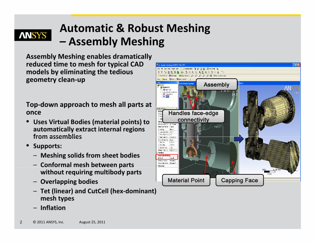
Automatic & Robust Meshing – Assembly Meshing
Assembly Meshing enables dramatically reduced time to mesh for typical CAD models by eliminating the tedious
Assembly Meshing
geometry clean‐up
Top‐down approach to mesh all parts atTop down approach to mesh all parts at once• Uses Virtual Bodies (material points) to automatically extract internal regions from assembliesfrom assemblies
• Supports:– Meshing solids from sheet bodies– Conformal mesh between parts pwithout requiring multibody parts
– Overlapping bodies– Tet (linear) and CutCell (hex‐dominant) mesh types
© 2011 ANSYS, Inc. August 25, 20112
mesh types– Inflation
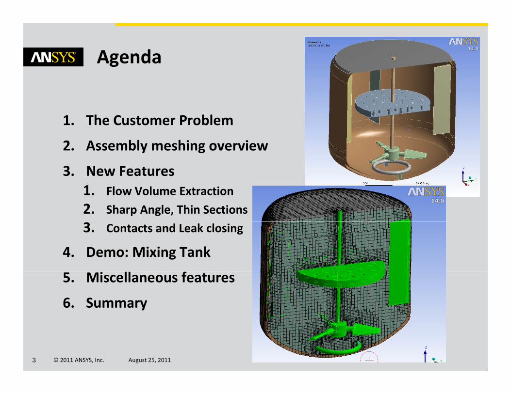
Agenda
1 The Customer Problem1. The Customer Problem
2. Assembly meshing overview
3 New Features3. New Features1. Flow Volume Extraction
2. Sharp Angle, Thin Sections
3. Contacts and Leak closing
4. Demo: Mixing Tank
f5. Miscellaneous features
6. Summary
© 2011 ANSYS, Inc. August 25, 20113
Automatic & Robust Meshing in Fluidsg
The Customer Problem
© 2011 ANSYS, Inc. August 25, 20114
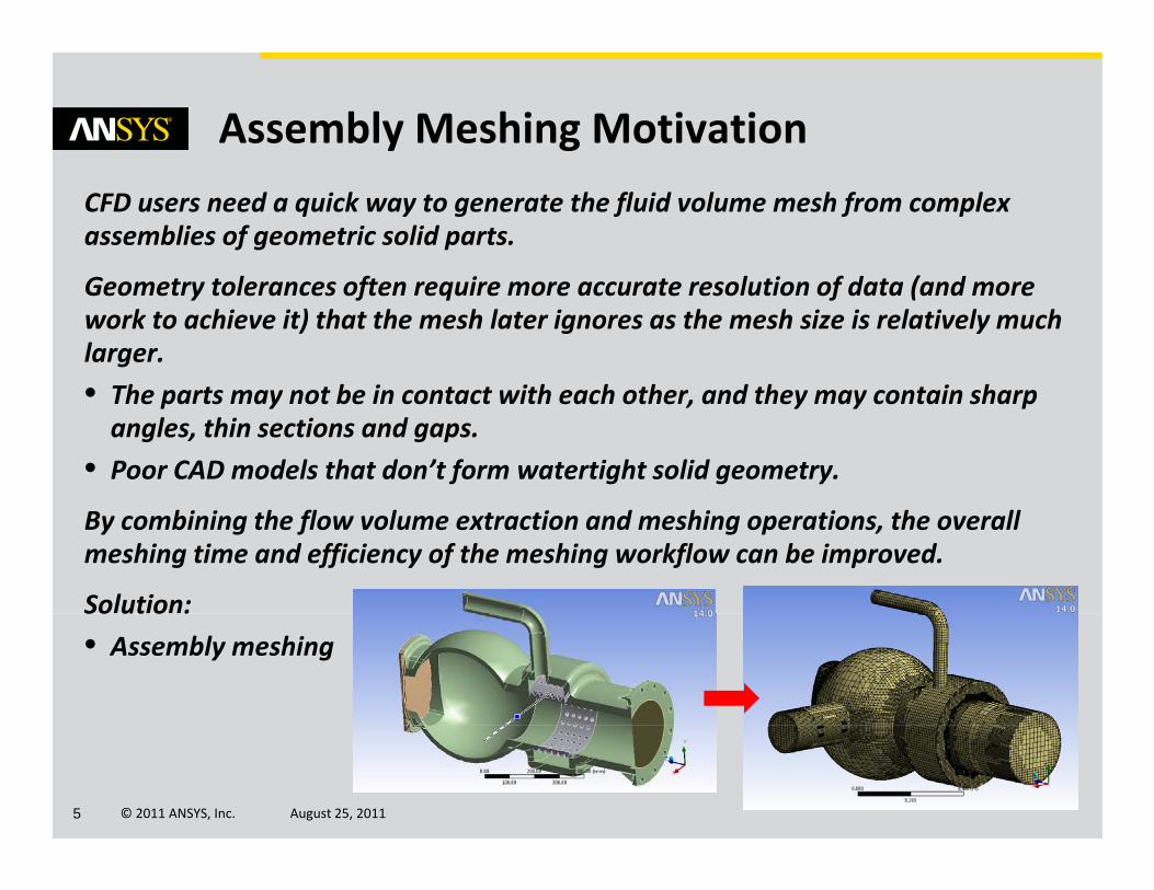
Assembly Meshing Motivation
CFD users need a quick way to generate the fluid volume mesh from complex assemblies of geometric solid parts.
G l f i l i f d ( dGeometry tolerances often require more accurate resolution of data (and more work to achieve it) that the mesh later ignores as the mesh size is relatively much larger.
• Th t t b i t t ith h th d th t i h• The parts may not be in contact with each other, and they may contain sharp angles, thin sections and gaps.
• Poor CAD models that don’t form watertight solid geometry.
By combining the flow volume extraction and meshing operations, the overall meshing time and efficiency of the meshing workflow can be improved.
Solution:So ut o :
• Assembly meshing
© 2011 ANSYS, Inc. August 25, 20115
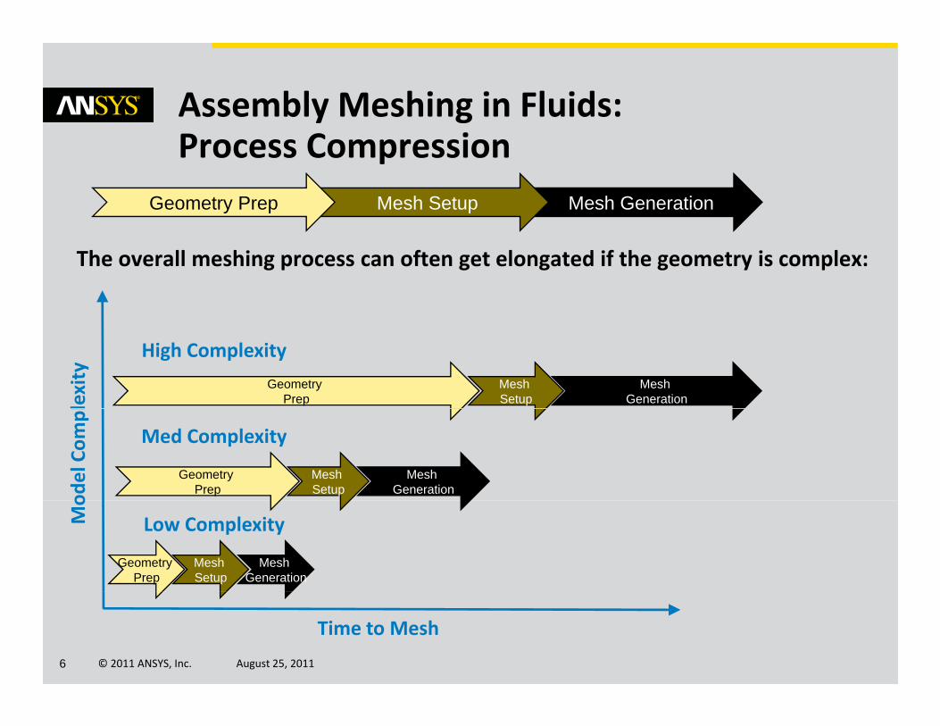
Assembly Meshing in Fluids: P C iProcess Compression
Mesh GenerationMesh SetupGeometry Prep
The overall meshing process can often get elongated if the geometry is complex:
lexity
Mesh Generation
Mesh Setup
Geometry Prep
High Complexity
odel Com
pl
Mesh Generation
Mesh Setup
Geometry Prep
Med Complexity
Mo
Mesh Generation
Mesh Setup
Geometry Prep
Low Complexity
© 2011 ANSYS, Inc. August 25, 20116
Time to Mesh
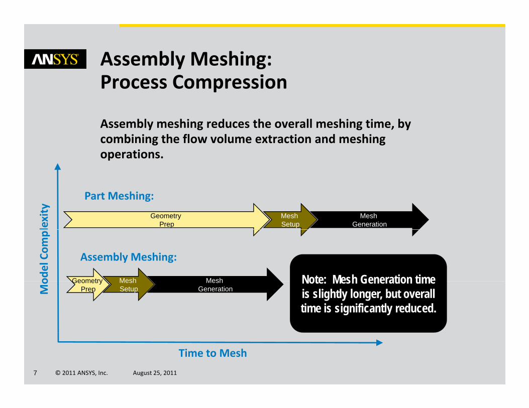
Assembly Meshing: P C iProcess Compression
Assembly meshing reduces the overall meshing time, byAssembly meshing reduces the overall meshing time, by combining the flow volume extraction and meshing operations.
lexity
Part Meshing:
Mesh Generation
Mesh Setup
Geometry Prep
odel Com
pl
MeshMesh
Assembly Meshing:
Geometry Note: Mesh Generation time
Mo Mesh
GenerationMesh Setup
Geometry Prep
Note: Mesh Generation time is slightly longer, but overall time is significantly reduced.
© 2011 ANSYS, Inc. August 25, 20117
Time to Mesh
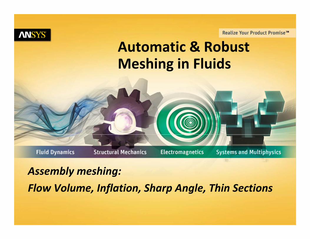
A tomatic & Rob stAutomatic & Robust Meshing in Fluids
Assembly meshing:
Flow Volume, Inflation, Sharp Angle, Thin Sections
© 2011 ANSYS, Inc. August 25, 20118
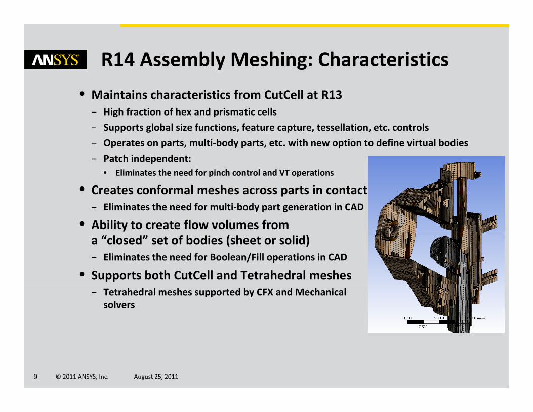
R14 Assembly Meshing: Characteristics
• Maintains characteristics from CutCell at R13– High fraction of hex and prismatic cells
– Supports global size functions feature capture tessellation etc controls– Supports global size functions, feature capture, tessellation, etc. controls
– Operates on parts, multi‐body parts, etc. with new option to define virtual bodies
– Patch independent: • Eliminates the need for pinch control and VT operations
• Creates conformal meshes across parts in contact– Eliminates the need for multi‐body part generation in CAD
• Ability to create flow volumes from a “closed” set of bodies (sheet or solid)– Eliminates the need for Boolean/Fill operations in CAD
• Supports both CutCell and Tetrahedral meshes– Tetrahedral meshes supported by CFX and Mechanical
solvers
© 2011 ANSYS, Inc. August 25, 20119
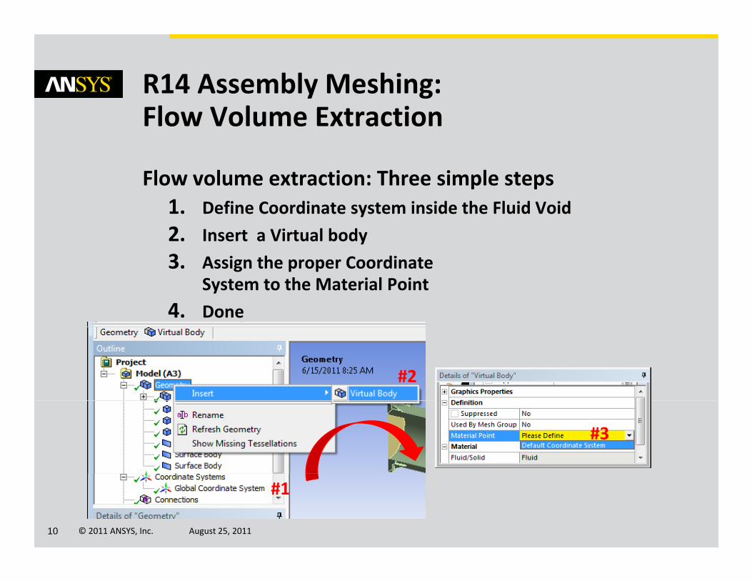
R14 Assembly Meshing: Fl V l E i
Flow volume extraction: Three simple steps
Flow Volume Extraction
Flow volume extraction: Three simple steps1. Define Coordinate system inside the Fluid Void
2. Insert a Virtual body
33. Assign the proper CoordinateSystem to the Material Point
4. Done
#2
#3
© 2011 ANSYS, Inc. August 25, 201110
#1
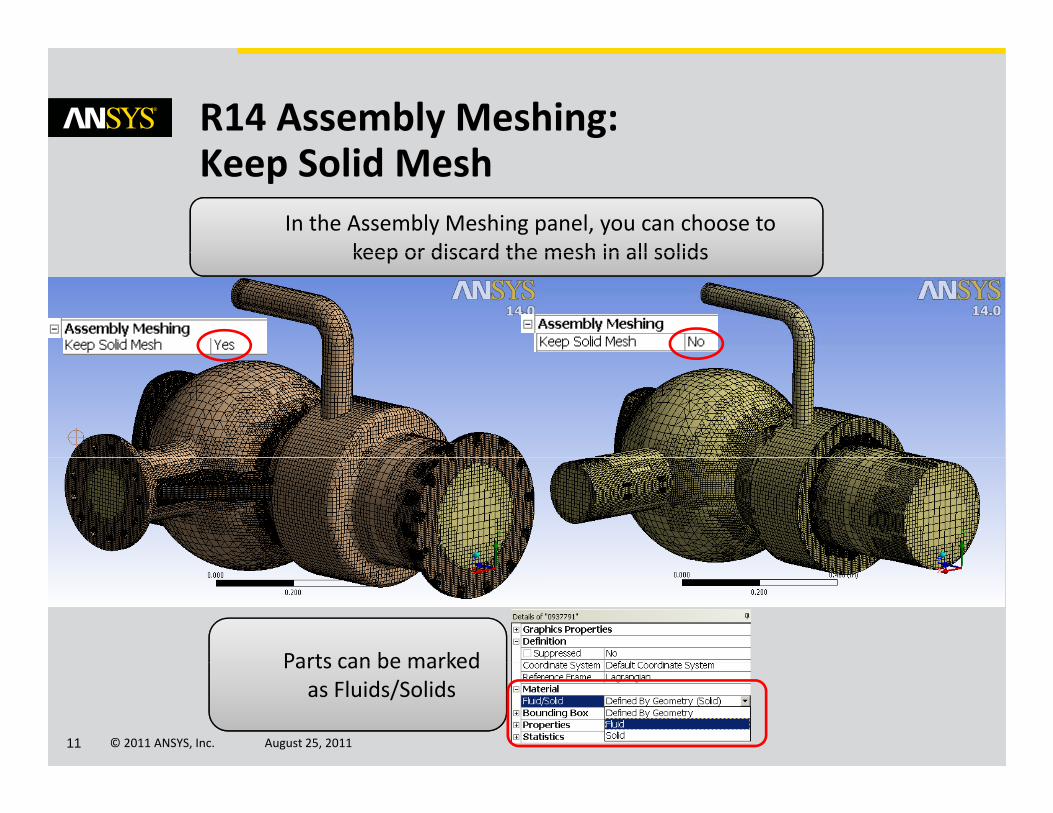
R14 Assembly Meshing:K S lid M hKeep Solid Mesh
In the Assembly Meshing panel, you can choose to keep or discard the mesh in all solidskeep or discard the mesh in all solids
Parts can be marked
© 2011 ANSYS, Inc. August 25, 201111
Parts can be marked as Fluids/Solids
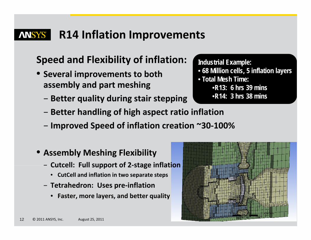
R14 Inflation Improvements
Industrial Example:• 68 Million cells, 5 inflation layers
Speed and Flexibility of inflation:• Several improvements to both • Total Mesh Time:
•R13: 6 hrs 39 mins•R14: 3 hrs 38 mins
Several improvements to both assembly and part meshing
– Better quality during stair stepping
– Better handling of high aspect ratio inflation
– Improved Speed of inflation creation ~30‐100%
• Assembly Meshing Flexibility– Cutcell: Full support of 2‐stage inflation– Cutcell: Full support of 2‐stage inflation
• CutCell and inflation in two separate steps
– Tetrahedron: Uses pre‐inflation• Faster more layers and better quality
© 2011 ANSYS, Inc. August 25, 201112
• Faster, more layers, and better quality

R14 Assembly Meshing: A i I fl i
Also supported for Flow volume extraction
Automatic Inflation
Also supported for Flow volume extraction
• Program controlled inflation acts only on Fluid Bodies
CutCell + Inflation Tetrahedron + Inflation
© 2011 ANSYS, Inc. August 25, 201113
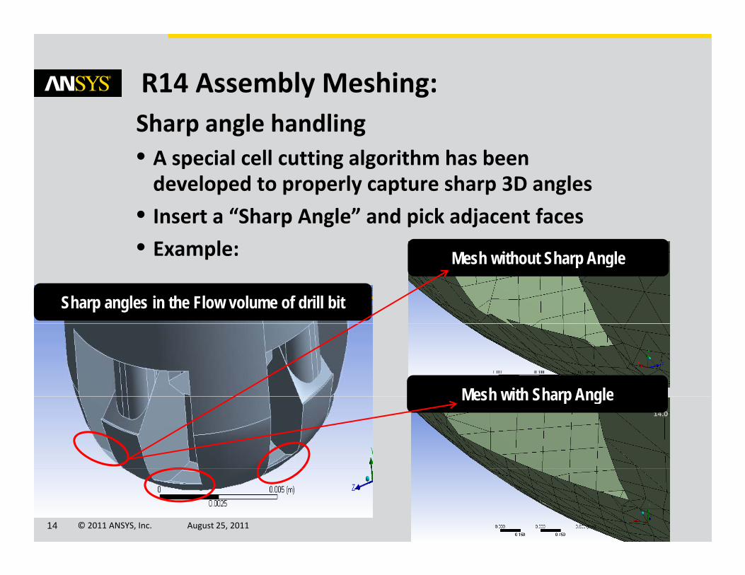
R14 Assembly Meshing:Sharp angle handling• A special cell cutting algorithm has been d l d t l t h 3D ldeveloped to properly capture sharp 3D angles
• Insert a “Sharp Angle” and pick adjacent faces
• Example:Example:
Sharp angles in the Flow volume of drill bit
Mesh without Sharp Angle
Mesh with Sharp AngleMesh with Sharp Angle
© 2011 ANSYS, Inc. August 25, 201114
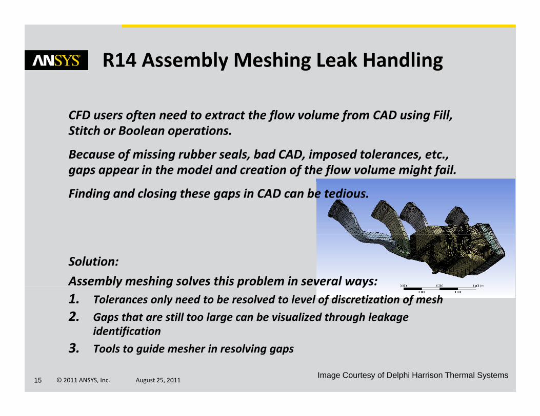
R14 Assembly Meshing Leak Handling
CFD users often need to extract the flow volume from CAD using Fill, Stitch or Boolean operationsStitch or Boolean operations.
Because of missing rubber seals, bad CAD, imposed tolerances, etc., gaps appear in the model and creation of the flow volume might fail.
Finding and closing these gaps in CAD can be tedious.
Solution:
Assembly meshing solves this problem in several ways:y g p y1. Tolerances only need to be resolved to level of discretization of mesh
2. Gaps that are still too large can be visualized through leakage identification
© 2011 ANSYS, Inc. August 25, 201115
3. Tools to guide mesher in resolving gaps
Image Courtesy of Delphi Harrison Thermal Systems
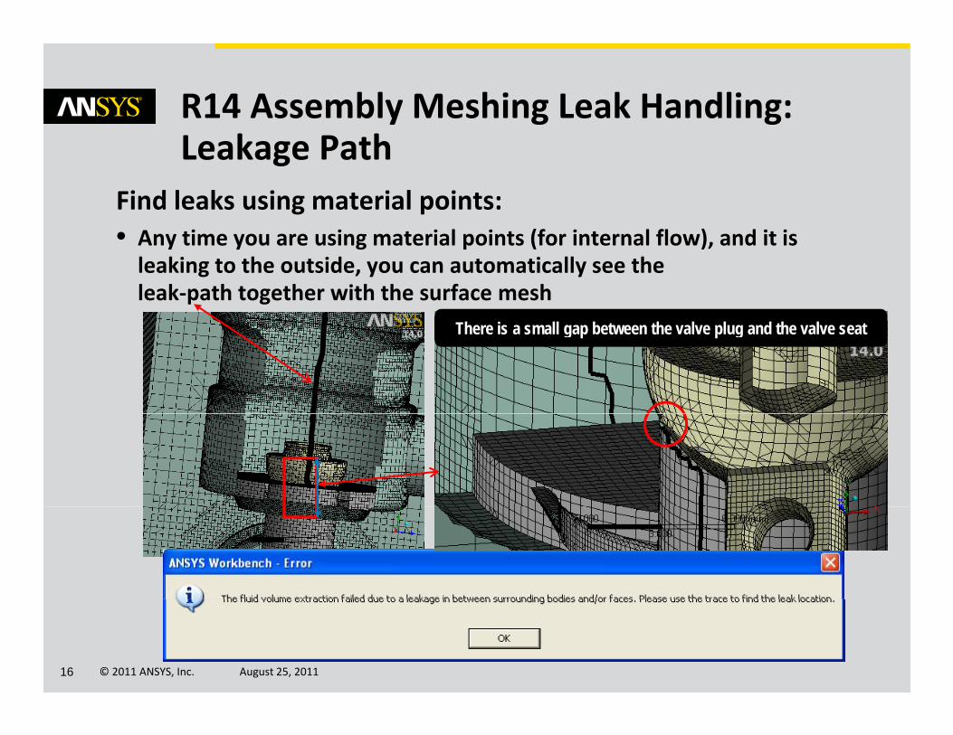
R14 Assembly Meshing Leak Handling:L k P h
Find leaks using material points:( )
Leakage Path
• Any time you are using material points (for internal flow), and it is leaking to the outside, you can automatically see the leak‐path together with the surface mesh
There is a small gap between the valve plug and the valve seat
© 2011 ANSYS, Inc. August 25, 201116
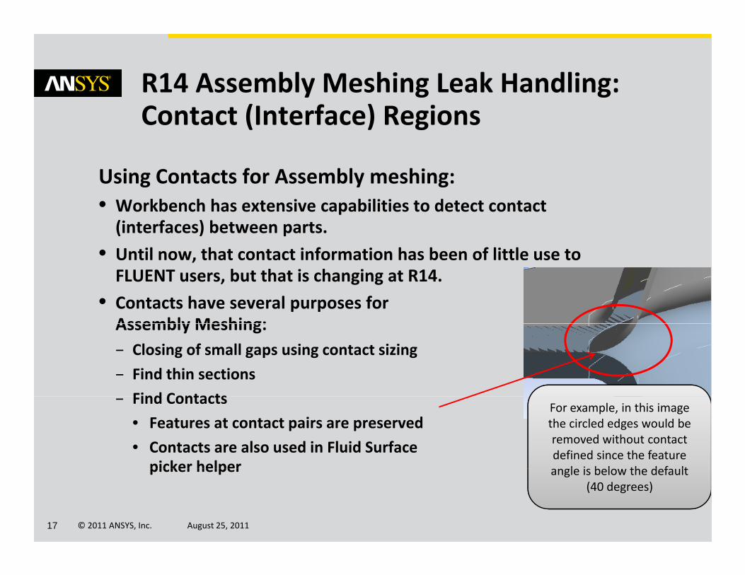
R14 Assembly Meshing Leak Handling:C (I f ) R i
Using Contacts for Assembly meshing:
Contact (Interface) Regions
Using Contacts for Assembly meshing:• Workbench has extensive capabilities to detect contact (interfaces) between parts.
• Until now that contact information has been of little use to• Until now, that contact information has been of little use to FLUENT users, but that is changing at R14.
• Contacts have several purposes for Assembly Meshing:Assembly Meshing:– Closing of small gaps using contact sizing
– Find thin sections
Find Contacts– Find Contacts
• Features at contact pairs are preserved
• Contacts are also used in Fluid Surface picker helper
For example, in this image the circled edges would be removed without contact defined since the feature angle is below the default
© 2011 ANSYS, Inc. August 25, 201117
picker helper angle is below the default (40 degrees)
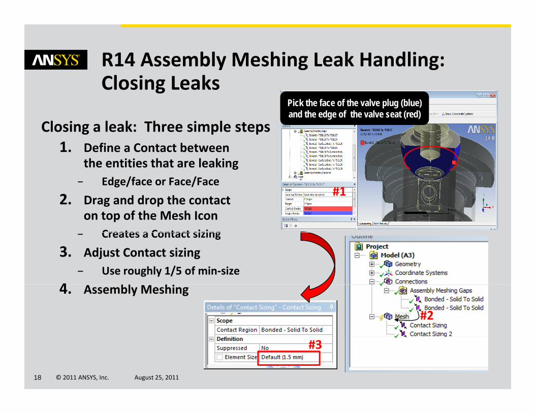
R14 Assembly Meshing Leak Handling:Cl i L k
Closing a leak: Three simple steps
Closing LeaksPick the face of the valve plug (blue)and the edge of the valve seat (red)
Closing a leak: Three simple steps1. Define a Contact between
the entities that are leakingEdge/face or Face/Face– Edge/face or Face/Face
2. Drag and drop the contacton top of the Mesh Icon
Creates a Contact sizing
#1
– Creates a Contact sizing
3. Adjust Contact sizing– Use roughly 1/5 of min‐size
4 bl hi4. Assembly Meshing
#2
© 2011 ANSYS, Inc. August 25, 201118
#3
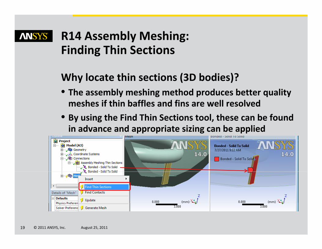
R14 Assembly Meshing:Fi di Thi S i
Why locate thin sections (3D bodies)?
Finding Thin Sections
Why locate thin sections (3D bodies)?• The assembly meshing method produces better quality meshes if thin baffles and fins are well resolved
• By using the Find Thin Sections tool, these can be found in advance and appropriate sizing can be applied
© 2011 ANSYS, Inc. August 25, 201119
A t ti & R b tAutomatic & Robust Meshing in Fluids
Assembly meshing: Mixing Tank Demo
© 2011 ANSYS, Inc. August 25, 201120
R14 Assembly Meshing ‐ Demo
© 2011 ANSYS, Inc. August 25, 201121
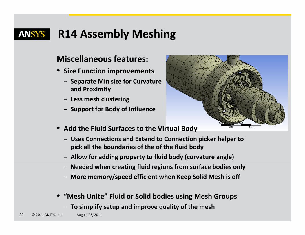
R14 Assembly Meshing
Miscellaneous features:• Size Function improvementsSize Function improvements
– Separate Min size for Curvature and Proximity
– Less mesh clustering
– Support for Body of Influence
• Add the Fluid Surfaces to the Virtual Body– Uses Connections and Extend to Connection picker helper to pick all the boundaries of the of the fluid body
– Allow for adding property to fluid body (curvature angle)
– Needed when creating fluid regions from surface bodies only
– More memory/speed efficient when Keep Solid Mesh is off
© 2011 ANSYS, Inc. August 25, 201122
• “Mesh Unite” Fluid or Solid bodies using Mesh Groups– To simplify setup and improve quality of the mesh
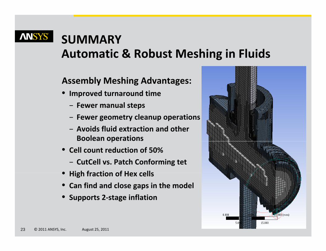
SUMMARY
A bl M hi Ad t
Automatic & Robust Meshing in Fluids
Assembly Meshing Advantages:• Improved turnaround time
– Fewer manual steps
– Fewer geometry cleanup operations
– Avoids fluid extraction and other Boolean operationsp
• Cell count reduction of 50%
– CutCell vs. Patch Conforming tet
• High fraction of Hex cells• High fraction of Hex cells
• Can find and close gaps in the model
• Supports 2‐stage inflation
© 2011 ANSYS, Inc. August 25, 201123
A t ti & R b tAutomatic & Robust Meshing in Fluids
THANK YOU 2011 ANSYS Regional Conferences
© 2011 ANSYS, Inc. August 25, 201124