AUTOMATIC ICE CUBE MACHINES - rses.org · Service Application Manual SAM Chapter 630-05 Section 09...
38
Service Application Manual SAM Chapter 630-05 Section 09 AUTOMATIC ICE CUBE MACHINES By: Stanley F. Gallus INTRODUCTION As far back as 1897, Britain granted a patent on a machine which produced clear ice cubes. The individual cells of the evaporator were partitioned by an insulating material and completely submerged. Agitation was provided to produce clear cubes. Harvesting was accomplished by passing a warm fluid under the evaporator until the cubes melted loose and floated to the top. New materials and components brought the basic design of this system to a fully automatic ice cube machine, of which many types are available today. Many shapes and sizes of ice are available in machines which either dump into their own storage compartment or into storage areas suited to meet individual requirements. Due to the fact that ice making machines produce ice in such varied shapes and sizes, some manufacturers refer to the product of their machines as "ice pieces," rather than "ice cubes." For the purpose of this discussion, the words "ice pieces" and "ice cubes" will be used interchangeably. "Ice cube" is the accepted term, by general usage, and does not necessarily refer to a specific cubical shape. CELL TYPE Cell type machines form ice in separate pieces which are harvested and stored. All of these types are formed individually and are completely clear. INVERTED CELL DESIGN One ice cube machine which produces solid, clear cubes uses an evaporator partitioned into cubical cells, mounted with the open end down. A sealing plate through which water is introduced and allowed to flow away forms the bottom side of the enclosure. The bottom plate being hinged, moves away from the cells on the harvest cycle, and the cubes drop and slide down the plate. There have been several variations of this same type. Some designs use inverted cells into which water is sprayed through a nozzle or nozzles. One design used a nozzle for each cell although this is not the general practice. When formation is completed, a thermostat or pressure control senses a drop in evaporator temperature or pressure. This occurs when the ice becomes thicker and heat transfer lessened. The control then actuates a solenoid valve which opens to allow hot discharge gas to enter the evaporator. This continues until the evaporator temperature rises indicating the harvest cycle is complete. One more simple design, uses inverted hexagon shaped cups which are embedded in a plastic grid. The grid prevents ice from bridging between the cups due to the low heat transfer through plastic. A grid heater is also embedded in the plastic to aid during the harvest cycle. A second heater is attached to the evaporator tubes which are bonded to the top of the freezing cups. 1
Transcript of AUTOMATIC ICE CUBE MACHINES - rses.org · Service Application Manual SAM Chapter 630-05 Section 09...

Service Application Manual SAM Chapter 630-05
Section 09
AUTOMATIC ICE CUBE MACHINES By: Stanley F. Gallus
INTRODUCTION
As far back as 1897, Britain granted a patent on a machine which produced clear ice cubes. The individual cells of the evaporator were partitioned by an insulating material and completely submerged. Agitation was provided to produce clear cubes. Harvesting was accomplished by passing a warm fluid under the evaporator until the cubes melted loose and floated to the top.
New materials and components brought the basic design of this system to a fully automatic ice cube machine, of which many types are available today.
Many shapes and sizes of ice are available in machines which either dump into their own storage compartment or into storage areas suited to meet individual requirements.
Due to the fact that ice making machines produce ice in such varied shapes and sizes, some manufacturers refer to the product of their machines as "ice pieces," rather than "ice cubes." For the purpose of this discussion, the words "ice pieces" and "ice cubes" will be used interchangeably. "Ice cube" is the accepted term, by general usage, and does not necessarily refer to a specific cubical shape.
CELL TYPE
Cell type machines form ice in separate pieces which are harvested and stored. All of these types are formed individually and are completely clear.
INVERTED CELL DESIGN
One ice cube machine which produces solid, clear cubes uses an evaporator partitioned into cubical cells, mounted with the open end down. A sealing plate through which water is introduced and allowed to flow away forms the bottom side of the enclosure. The bottom plate being hinged, moves away from the cells on the harvest cycle, and the cubes drop and slide down the plate. There have been several variations of this same type.
Some designs use inverted cells into which water is sprayed through a nozzle or nozzles. One design used a nozzle for each cell although this is not the general practice.
When formation is completed, a thermostat or pressure control senses a drop in evaporator temperature or pressure. This occurs when the ice becomes thicker and heat transfer lessened. The control then actuates a solenoid valve which opens to allow hot discharge gas to enter the evaporator. This continues until the evaporator temperature rises indicating the harvest cycle is complete.
One more simple design, uses inverted hexagon shaped cups which are embedded in a plastic grid. The grid prevents ice from bridging between the cups due to the low heat transfer through plastic. A grid heater is also embedded in the plastic to aid during the harvest cycle. A second heater is attached to the evaporator tubes which are bonded to the top of the freezing cups.
1

Service Application Manual SAM Chapter 630-05
Section 09
AUTOMATIC ICE CUBE MACHINES By: Stanley F. Gallus
Water is admitted to a water tank through a solenoid valve. The water rises to a level that creates a static head pressure which compresses the air within the air trap tube. (Figure 36F03) The compressed air actuates a pressure switch which de-energizes the "water-in" solenoid valve. At this time, the water tank contains enough water to complete one freezing cycle.
2

Service Application Manual SAM Chapter 630-05
Section 09
3
AUTOMATIC ICE CUBE MACHINES By: Stanley F. Gallus
Schematic Drawings; Side View of Hexagon Cell Type Ice Cuber

Service Application Manual SAM Chapter 630-05
Section 09
AUTOMATIC ICE CUBE MACHINES By: Stanley F. Gallus
Water is pumped to a spinning water distributor which acts similar to a lawn sprinkler. The ice pieces form from the sides of the hexagon cell, inward a short distance, closing thermostat contacts, which starts a timer. After 30 seconds, a holding circuit is provided through the timer paralleling the bin and evaporator thermostat. Ten minutes after the timer starts, the harvest cycle begins. Both heaters are energized to add heat to the sides and top of the freezing cavities. The grid heater is de-energized first, followed by the tube heater 3 minutes later. This ends the harvest cycle and begins another freezing cycle. Figure 36F02B shows the control circuit.
4

Service Application Manual SAM Chapter 630-05
Section 09
AUTOMATIC ICE CUBE MACHINES By: Stanley F. Gallus
Control Circuit Wiring Diagram
Occasionally one or several nozzles may become obstructed, due to mineral deposits at the orifice, causing the spray to deflect and miss the cell. If only one side is hit by the spray, the ice piece will not form completely and irregular pieces will result.
If the harvest time is too short, due to an improperly adjusted control, some of the pieces may not release and refreezing will occur. The refrozen pieces will extend beyond the boundaries of the cell and fuse with the adjacent cubes.
One cell type cuber whose cycle is rather unique (Figure 36F04) operates as follows: At the beginning of the freezing cycle, a water reservoir and sump tank are filled enough to produce one complete batch of ice.
Schematic of Cylindrical Cell Type Ice Cuber, on Freezing Cycle
A timer closes a circuit to the compressor, pump and heater element in the hot water tank, as well as opens the circuit to the timer motor; (timer does not operate during the first 20 minutes). Water is sprayed to the inverted cells through jets inserted in a sprayer tube. The sprayer tube
5

Service Application Manual SAM Chapter 630-05
Section 09
AUTOMATIC ICE CUBE MACHINES By: Stanley F. Gallus
rocks back and forth by means of an arm attached between it and the agitator drive motor. This action of the spray covers the complete platen of cells.
After a pre-determined amount of ice is frozen, a reverse acting pressure control starts the timer motor which continues the freezing cycle for approximately 9 more minutes. At the end of that time, it stops the compressor, agitator and pump and breaks the circuit to the heater element. The water valve solenoid is energized, admitting hot water by gravity to the top section of the cell cavities, and at the same time, drains the surplus water from the reservoir and sump.
The hot water in contact with the cells melts the cubes free, and they fall into the storage chamber. After the defrost cycle is complete, the solenoid reverses itself through action of the timer. The hot water which was used for defrost, having been cooled off, is used for the next batch of ice by dumping it into the reservoir and sump. The water valve now allows the hot water tank to refill. The clock motor terminates the defrost cycle and starts the freezing cycle again. (Figures 36F05A & 36F05B).
Manufacturer's Wiring Diagram for Cylindrical Cell Type Ice Cuber
6

Service Application Manual SAM Chapter 630-05
Section 09
7
AUTOMATIC ICE CUBE MACHINES By: Stanley F. Gallus
RSES Troubleshooting Diagram For The Above Cuber. Note That all Controls are Shown “Across the Line” in Series With the Load They Operate
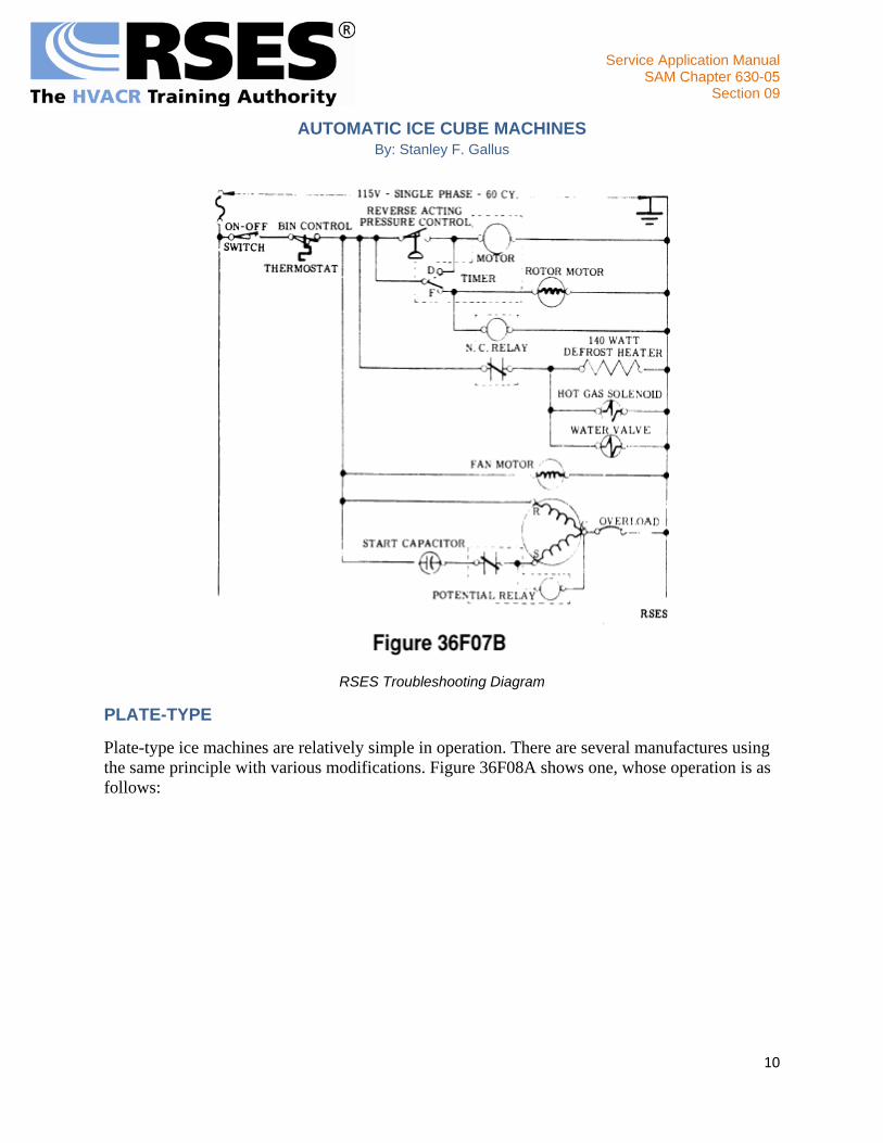
Another cell type machine has the individual copper cells inverted in a sealed pan type flooded evaporator. Refrigerant completely surrounds the cells, having all primary heat transfer surface. Water is slung upward from rotating discs which are partially submerged in water. (Figure 36F06) Water which is not frozen drops back into the reservoir to be recirculated. When the evaporator pressure is reduced to 7-9 psig, using R-12, a reverse acting pressure control starts a timer. After a pre-determined length of time, the timer starts the harvest cycle by opening the circuit to the rotor motor and the relay circuit, which allows the normally closed relay contacts to close . This energizes the water inlet valve, hot gas solenoid and defrost heater. The timer terminates the harvest cycle through a cam arrangement within the timer. As the cubes fall, they slide down a sloping grid into the storage compartment. A thermostat senses a full storage bin and opens to stop the complete system. (Figures 36F07A & 36F07B)

Service Application Manual SAM Chapter 630-05
Section 09
8
AUTOMATIC ICE CUBE MACHINES By: Stanley F. Gallus

Service Application Manual SAM Chapter 630-05
Section 09
AUTOMATIC ICE CUBE MACHINES By: Stanley F. Gallus
Cut-Away View of Cylindrical Cell Ice Cuber Using Flooded Evaporator
Manufacturer's Wiring Diagram of Unit Shown in Figure 36F06
9
Service Application Manual SAM Chapter 630-05
Section 09
10
AUTOMATIC ICE CUBE MACHINES By: Stanley F. Gallus
RSES Troubleshooting Diagram
PLATE-TYPE
Plate-type ice machines are relatively simple in operation. There are several manufactures using the same principle with various modifications. Figure 36F08A shows one, whose operation is as follows:
Service Application Manual SAM Chapter 630-05
Section 09
11
AUTOMATIC ICE CUBE MACHINES By: Stanley F. Gallus
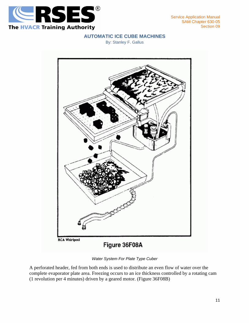
Water System For Plate Type Cuber
A perforated header, fed from both ends is used to distribute an even flow of water over the complete evaporator plate area. Freezing occurs to an ice thickness controlled by a rotating cam (1 revolution per 4 minutes) driven by a geared motor. (Figure 36F08B)

Service Application Manual SAM Chapter 630-05
Section 09
12
AUTOMATIC ICE CUBE MACHINES By: Stanley F. Gallus
Ice Thickness Control
As the ice slab thickens, it obstructs the movements of the cam and raises the cam and arm attachment high enough to close a micro-switch starting the defrost cycle. The cam and cam arm can be adjusted to obtain any ice thickness within the limits of the machine.
One manufacturer uses a large surface area contact thermostat which can be raised or lowered to vary the ice thickness.
The water which is not frozen, drops into a reservoir to be recirculated. At the start of the defrost cycle, the water pump stops but the compressor continues. All the circulated water falls into the reservoir and overflows through a small standpipe.
This overflow starts a siphoning action which completely flushes the reservoir of any sediment which may have settled during the freezing cycle. This dumping action occurs with every defrost cycle.

Service Application Manual SAM Chapter 630-05
Section 09
AUTOMATIC ICE CUBE MACHINES By: Stanley F. Gallus
The inlet water tube is twisted around the drain tube from the storage area so that a transfer of heat will be affected. This lowers the inlet water temperature, increasing the units ice production. NOTE:
Precautions must be taken when cleaning the plate, to avoid scoring the surface. If the ice produced is not completely solid, the cause is concentrated mineral deposits.
Partial slabs could result from shortage of refrigerant, or a partially clogged screen at the thermostatic expansion valve inlet. The hot gas solenoid could be leaking, permitting some discharge gas to enter the evaporator.
The grid used to cut the slab into cubes is low voltage and is fused for a 5 ampere draw. If a metallic object is dropped upon the grid, the 5 ampere fuse will blow as with a short. Figure 36F08C shows the electrical system.
13

Service Application Manual SAM Chapter 630-05
Section 09
14
AUTOMATIC ICE CUBE MACHINES By: Stanley F. Gallus
Top: Line Diagram – Bottom: Wiring Diagram

Service Application Manual SAM Chapter 630-05
Section 09
AUTOMATIC ICE CUBE MACHINES By: Stanley F. Gallus
In one other machine, the ice is cut into cubes by a grid of needle-like tubes through which hot discharge gas flows.
A different plate-type cuber uses two vertical plates approximately 1" apart. Evaporator tubes are in contact with one side of each plate. On the opposite side where freezing occurs, copper buttons are bonded to the plate. The heat transfer through the copper buttons is much higher than that of the plate.
Water is fed to a distributor pan which directs the flow through holes in the bottom. As the water passes from the distributor pan, it is baffled to both plates equally. As the water flows downward, freezing occurs at the copper buttons forming circular lenses. The balance of water then drops into the reservoir pan to be recirculated. The water circuit is shown in Figure 36F09B.
Water Circuit – LEFT: Side View; RIGHT: End View
A selector control determines the size of the cube. A thermostat bulb mounted within a capillary sheath near the cube formation (Figure 36Fl0A) terminates the freezing cycle by sensing a drop in temperature. Two sizes of cubes can be selected by raising or lowering the bulb location through a manual cam operated selector knob. If large cubes are desired, the freezing cycle continues until the lens on one side has fused to the lens directly opposite it. The resultant shape is that of a pulley.
15

Service Application Manual SAM Chapter 630-05
Section 09
AUTOMATIC ICE CUBE MACHINES By: Stanley F. Gallus
Since the thermostat is located between the evaporator plates, it is subjected to temperatures lower than the cut-in setting. To keep the temperature above the cut-in point, a heater attached to the capillary sheath keeps the temperature above the cut-in point until the ice formation touches the sheath. (Figure 36F10A) A sudden drop in temperature begins the harvest cycle.
A condenser fan thermostat is used to keep a nearly constant condensing pressure. A capillary tube is used as a metering device which eliminates the necessity of a high starting torque compressor. If the compressor is required to start a short period after stopping, it is necessary to push in a button which energizes a hot gas solenoid. In this case, it acts as a by-pass to unload the compressor. The same solenoid is used during the hot gas defrost cycle but is actuated directly by the thermostat. (Figures 36F10B & 36F10C)
16

Service Application Manual SAM Chapter 630-05
Section 09
17
AUTOMATIC ICE CUBE MACHINES By: Stanley F. Gallus
Manufacturer's Wiring Machine

Service Application Manual SAM Chapter 630-05
Section 09
18
AUTOMATIC ICE CUBE MACHINES By: Stanley F. Gallus
RSES Troubleshooting Diagram. All Switches Shown in Position For The Freezing Cycle. The Ice-Size Thermostat Initiates The Harvest Cycle by Closing the Circuit to the Hot-Gas Solenoid and Primary
Heater.
PLATE-TYPE WITH CRUSHER
One particular ice machine freezes twin slabs of ice, approximately 1/8" thick, on evaporators that are slightly tipped off vertical. (Figure 36F11A) Water is pumped through twin headers down the sloping evaporators. The water that is not frozen drops into the sump to be recirculated. A small amount of water is continually bled-off to prevent the concentration of minerals that lead to scaling. The bleed off water passes through a simple heat exchanger which cools the make up water.

Service Application Manual SAM Chapter 630-05
Section 09
19
AUTOMATIC ICE CUBE MACHINES By: Stanley F. Gallus
Schematic Drawing of Ice and Water System
Harvest begins when ice reaches the diverting blade, which channels some of the freezing water to the thermo well. The thermostat senses a drop in temperature and energizes the hot gas solenoid, at the same time stopping the water pump. When the slabs fall free of the evaporator, they are broken into irregular shapes through the built in crusher which only operates during the harvest cycle. Figure 36F11B shows the electrical control arrangement.

Service Application Manual SAM Chapter 630-05
Section 09
20
AUTOMATIC ICE CUBE MACHINES By: Stanley F. Gallus
Line Diagram of Control Circuit For Unit Shown in Figure 36F11A
TUBE-TYPE
One design of tube-type ice cube machine, has water flow through vertical tubes which freezes on its way down. (Figure 36F12) The method of terminating this freezing cycle is a small control evaporator. The evaporator tubes first contact the control evaporator tube and then the main

Service Application Manual SAM Chapter 630-05
Section 09
AUTOMATIC ICE CUBE MACHINES By: Stanley F. Gallus
evaporator section. Water is frozen in the control evaporator and the main evaporator simultaneously. The water freezes inward from the sides, until the flow path becomes restricted. The water backs up in the control evaporator, creating an air pressure on the underside of a diaphragm which actuates a switch terminating the freezing cycle and starting the defrost cycle.
Circulation of Water Through Evaporator and Control Evaporator
Earlier models used a thermostat which was inserted in a spill-over tube leading from the control evaporator. When the path of water was restricted by the freezing within the tube, the water would back up and spill over into a tube. The thermostat sensing the cold water would actuate a relay to start the defrost cycle.
21

Service Application Manual SAM Chapter 630-05
Section 09
AUTOMATIC ICE CUBE MACHINES By: Stanley F. Gallus
The freezing tubes are bonded to the evaporator tubes. To obtain a larger contact surface between the freezing tubes and the evaporator tubes, the evaporator tubes are flattened before bonding.
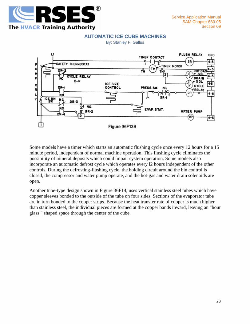
This same cuber will also produce various size ice chips within the same freezing tubes by stopping the freezing cycle before the cube freezes to full size. The chip shape takes on the appearance of a rectangular lens. The control evaporator is not used in this sequence to terminate freezing. A thermostat in series with the pressure switch senses a drop in evaporator temperature as the ice thickens and terminates the freezing cycle. Figure 36F13A shows the system operation in the harvest cycle, while Figure 36F13B shows a typical electrical control diagram.
22
Service Application Manual SAM Chapter 630-05
Section 09
23
AUTOMATIC ICE CUBE MACHINES By: Stanley F. Gallus
Some models have a timer which starts an automatic flushing cycle once every 12 hours for a 15 minute period, independent of normal machine operation. This flushing cycle eliminates the possibility of mineral deposits which could impair system operation. Some models also incorporate an automatic defrost cycle which operates every l2 hours independent of the other controls. During the defrosting-flushing cycle, the holding circuit around the bin control is closed, the compressor and water pump operate, and the hot-gas and water drain solenoids are open.
Another tube-type design shown in Figure 36F14, uses vertical stainless steel tubes which have copper sleeves bonded to the outside of the tube on four sides. Sections of the evaporator tube are in turn bonded to the copper strips. Because the heat transfer rate of copper is much higher than stainless steel, the individual pieces are formed at the copper bands inward, leaving an "hour glass " shaped space through the center of the cube.

Service Application Manual SAM Chapter 630-05
Section 09
24
AUTOMATIC ICE CUBE MACHINES By: Stanley F. Gallus
Schematic View of Tube–Type Ice Maker in the Freezing Cycle
Water is fed through a header and nozzle arrangement located at the top of the evaporator tube freezing section, Figure 36F15A. Water flowing downward freezes at the copper band sections until the formation of ice restricts the normal flow and causes a backup. The backup water flows into an overflow trough and drops into the thermostat well actuating the harvest cycle.

Service Application Manual SAM Chapter 630-05
Section 09
25
AUTOMATIC ICE CUBE MACHINES By: Stanley F. Gallus
Tube Type Ice Maker, Showing Internal Parts Arrangement
The hot gas solenoid opens, melting the cubes loose from the freezing tubes. In the event the cubes fail to drop, the backup water will overflow the thermo well and actuate a safety switch shutting off the complete system.
The control thermostat is a single pole double throw switch which begins the freezing cycle when the hot gas has warmed the evaporator sufficiently to terminate the harvest cycle. (Figure 36F15B)

Service Application Manual SAM Chapter 630-05
Section 09
26
AUTOMATIC ICE CUBE MACHINES By: Stanley F. Gallus
Wiring Diagram of Ice Maker With Crusher
ROD-TYPE
The rod-type ice machine has an evaporator which is constructed of rectangular tubes bonded together to produce a series arrangement. The tips are submerged to a depth, depending on the water level in the reservoir. This level can be adjusted to produce a variable length ice piece.
As the water freezes to the tips of the evaporator, a simple arm type paddle, which rotates between the evaporator sections and agitates the water to produce clear ice pieces. When the ice accumulates to a thickness which obstructs the path of the paddle wheels, a slip clutch which is built into the paddle drive motor swings the motor and extending arm attachments in the direction of rotation. This arm hits a switch mechanism which starts the harvest cycle. A separate geared motor with cam attachments lowers the complete water pan dumping the remaining water and starting the harvest cycle.

Service Application Manual SAM Chapter 630-05
Section 09
AUTOMATIC ICE CUBE MACHINES By: Stanley F. Gallus
Hot gas is discharged into the evaporator section melting the ice pieces free from the evaporator. The cam operates a switch which terminates the defrost cycle and lifts the pan into operating position through action of the motor. When the pan is positioned, water flows through a solenoid control valve and fills the pan. A float with a micro-switch attachment senses the water level and breaks the circuit to the solenoid. The cycle continues until the weight of the ice on the bin shelf opens the bin switch. (Figures 36F16B and 36F17A)
Factory Wiring Diagram
27

Service Application Manual SAM Chapter 630-05
Section 09
28
AUTOMATIC ICE CUBE MACHINES By: Stanley F. Gallus
RSES Troubleshooting Diagram Switches Shown in Position for Freezing
Since the paddles rotate exactly between the evaporator sections, bending one arm of the paddle towards the evaporator tip regulates the ice piece thickness.
In one rod-type cuber, short refrigerated rods about 3/8" diameter are immersed in an agitated tank of water. Bulb like pieces of ice are formed clinging to the tubes. At a predetermined time, the complete evaporator attachment is lifted from the water and the ice harvested through a defrost cycle.
A similar rod-type machine keeps the evaporator inverted rods permanently submerged. The bulb like pieces float to the top of the tank during defrost and are nudged over a spillway into a bin by a paddle wheel which also agitates the water.

Service Application Manual SAM Chapter 630-05
Section 09
AUTOMATIC ICE CUBE MACHINES By: Stanley F. Gallus
MOLD-TYPE
Several automatic ice makers of low capacity ice production were developed to encompass the area of small commercial and domestic application. One method used is a direct contact plate or mold which, through conduction of heat to the primary evaporator, freezes a small quantity of water (200 ml).
The primary evaporator is of the same type as used by household refrigeration systems. Two methods of heat transfer have been used to provide heat removal from the ice cube tray; direct contact with the refrigerated shelf and forced air.
A single pole double throw thermostat is used to switch from the harvest cycle to the freezing cycle and conversely from the freezing cycle to the harvest cycle. During the freezing cycle, the thermostat is in the warm position, which de-energizes all circuits. Since the aluminum mold is in direct contact with the primary evaporator surface, freezing of the water in the mold partition occurs.
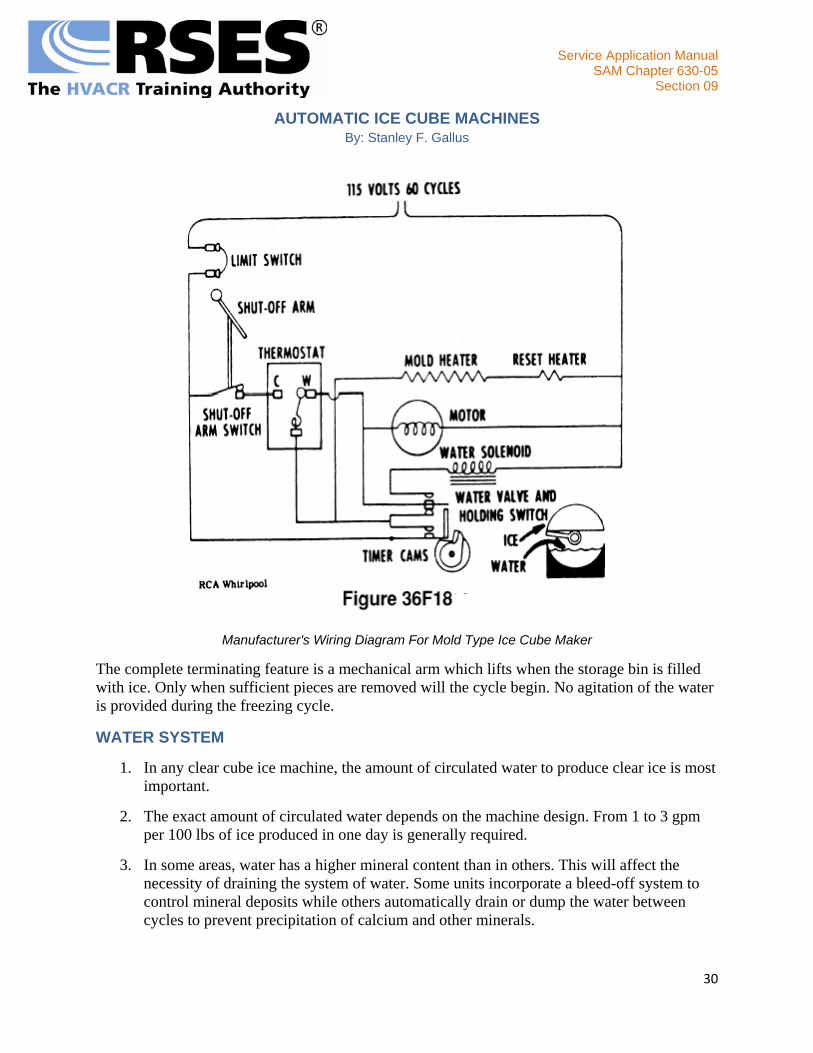
The thermostat senses a drop in temperature which energizes the geared motor and heater element. The heater element is attached to the bottom of the aluminum mold, and frees the ice piece from the mold. Simultaneously, the geared motor revolves a shaft which is attached to ejector blades. Through a simple cam arrangement of the geared motor, a bypass or holding circuit is introduced to assure the completion of the ejection cycle. The ejector blades rotate until in contact with the ice pieces still firmly adhered to the mold. The gear motor stalls and remains energized until the ice pieces melt free from the mold. The ejector blade then continues to rotate, lifting the ice from the mold. The outer timing cam energizes the water solenoid valve which refills the now empty mold. A small heater in series with the mold heater resets the thermostat for the next freezing cycle.
The cycle ends when the cam rotates to a position which opens the holding contacts. Water which is in the lower section of the mold evaporator section begins to freeze and the same cycle repeats itself over and over again. Figure 36F18 shows the control circuit wiring diagram.
29
Service Application Manual SAM Chapter 630-05
Section 09
30
AUTOMATIC ICE CUBE MACHINES By: Stanley F. Gallus
Manufacturer's Wiring Diagram For Mold Type Ice Cube Maker
The complete terminating feature is a mechanical arm which lifts when the storage bin is filled with ice. Only when sufficient pieces are removed will the cycle begin. No agitation of the water is provided during the freezing cycle.
WATER SYSTEM
1. In any clear cube ice machine, the amount of circulated water to produce clear ice is most important.
2. The exact amount of circulated water depends on the machine design. From 1 to 3 gpm per 100 lbs of ice produced in one day is generally required.
3. In some areas, water has a higher mineral content than in others. This will affect the necessity of draining the system of water. Some units incorporate a bleed-off system to control mineral deposits while others automatically drain or dump the water between cycles to prevent precipitation of calcium and other minerals.

Service Application Manual SAM Chapter 630-05
Section 09
AUTOMATIC ICE CUBE MACHINES By: Stanley F. Gallus
4. Increased speed of freezing traps air and minerals, resulting in cloudiness of the cubes.
Most machines operate under varying condensing temperature conditions without trouble. These conditions may vary from manufacturer, but temperatures between 45°F and 110°F ambient for air cooled; and water temperatures between 45°F and 90°F for water cooled machines, are acceptable.
The general method of circulation where water is required to flow through an orifice is an impeller type pump. Orifices are used to control the direction, spread and velocity of the water. When water conditions are poor, orifices accumulate a mineral deposit and tend to clog.
When partial clogging exists, the direction of spray may be diverted, and as a result, will not hit the cell, or cover the entire evaporator surface. The spread could be affected and create the same problems. Systems thus affected should be provided with some means of countering these effects. Provisions for filtering, softening or bleed-off will help to alleviate fast foul-up conditions.
In many cases, bleed-off water has to be increased to eliminate the precipitation of minerals. If the amount of bleed-off water is less than that necessary to keep the minerals in suspension, settling will occur.
Make up water is generally controlled through a simple float mechanism or an inlet solenoid valve.
The inlet water pressure required varies with the individual machine. Some units require not less than 35 psig at the inlet or the effects such as mineral deposits, incomplete freezing, etc., will occur. Generally, the operating range is from 15 psig to 100 psig.
TIMERS
The general application of a timer within a cuber circuit is terminating the freezing cycle. At the start of many freezing cycles, the timer is not energized until the cube is partially formed. A control device, such as a thermostat senses a drop in evaporator temperature indicating a partial forming. The thermostat will then cut-in the timer to complete the freezing cycle and also start the harvest cycle. In some machines, the timer will terminate the defrost cycle but in others, a reverse acting control accomplishes the same thing.
TROUBLESHOOTING
Due to the fact that there are so many types of automatic ice cube machines in use, it would be impractical to include a troubleshooting chart for each type. Also, many troubleshooting procedures are common to all, or several types of machines. Equipped with a thorough understanding of the cycle of operation, the service engineer should be able to troubleshoot practically any automatic ice cube machine using the following troubleshooting guide. (Table 1) An understanding of troubleshooting the basic refrigeration system is assumed.
31

Service Application Manual SAM Chapter 630-05
Section 09
AUTOMATIC ICE CUBE MACHINES By: Stanley F. Gallus
ALL TYPES
CONDITION POSSIBLE CAUSE CORRECTION
Compressor does not operate.
Blown fuse. Replace fuse.
Control Circuit malfunction. Trace circuit with continuity tester and replace defective control.
Compressor starting circuit malfunction. Trace starting circuit and replace faulty component.
Open or shorted Motor-compressor winding. Replace Motor-Compressor.
Compressor operates intermittently.
Compressor Overload opens.
Check for low voltage; defective start relay or run capacitor; dirty condenser, or faulty water valve.
Low Pressure Switch opens and closes.
Check for low refrigerant charge; TEV power element lost charge; Blocked TEV orifice, restricted liquid line filter-drier.
High Pressure Switch opens and closes.
Check for dirty condenser, check condenser fan. Check water supply and water regulating valve (water cooled).
Control circuit malfunction. Trace control circuit and replace faulty part.
Cloudy ice cubes.
Excessive minerals in water supply. Treat water, as required. Dirty water supply. Use filter. Accumulation of minerals due to plugged drain or bleed. Clean water system.
Shortage of water. Check water supply, inlet valve or water level control.
Improper agitation. Observe system operation and correct as necessary.
Low capacity.
Improper refrigeration. Check refrigeration system operation. High room ambient temperature. Relocate, or increase ventilation.
High condensing temperature
Clean condenser. Check condenser fan. Check condenser water valve.
Restriction in water system. Check and correct. Loss of water or low water level. Check and correct as necessary.
Irregular cubes.
Unit not level. Level as necessary. Water orifices plugged. Acid clean water system. Erratic cube size control. Check and replace if required.
Water flowing over cubes after harvest. Adjust cube rack, or make other adjustments as required.
CELL TYPE
CYLINDRICAL OR HEXAGON
CONDITION POSSIBLE CAUSE CORRECTION
Shortage of water.
Water spraying through curtain. Replace any broken curtains. Adjust travel or jet tube.
Water inlet valve leaking. Check valve for dirt. Replace seats if required. Water entering hot water tank too slowly. Adjust pressure reducing valve. Clean strainer.
32

Service Application Manual SAM Chapter 630-05
Section 09
AUTOMATIC ICE CUBE MACHINES By: Stanley F. Gallus
Cubes too small.
Cube size control set high. Lower setting. Improper refrigeration. Check system and correct. Shortage of water. See "Shortage of water" above.
Poor harvest.
Short defrost time. Check and adjust. Open electric heater or hot gas solenoid circuit. Check with continuity tester.
Low water temperature. Temperature of water in hot tank should be 130-140°F.
Insufficient hot water. Adjust water level in float chamber.
PLATE TYPE
SQUARE OR RECTANGULAR
Evaporator plate does not build up ice.
Defrost valve stuck open. Check solenoid valve; coil. Tap Valve. If needle drops, replace valve.
Inefficient compressor. Replace compressor.
Ice thickness control switch did not reset. Check to see if water is circulating. If not, check for bind in linkage control.
Ice slab will not release during defrost period.
Ice thickness control stuck in freeze position. Check linkage of control or replace control.
Hot gas solenoid fails to open. Coil may be open or grounded. Ice thickness control defective.
Ice thickness control out of adjustment. Adjust. Ice thickness control motor inoperative. Replace. Mineral deposits holding slab. Clean evaporator plate.
Ice thickness incorrect.
Ice thickness control not adjusted properly. Adjust screw on control for proper thickness.
Ice thickness control motor inoperative. Check and replace motor if necessary. Make sure cam contacts ice.
Slow slab release.
Low ambient. Change location.
Mineral build up on evaporator plate. Clean evaporator plate and treat water if necessary.
Pitted freezer plate. Wax plate with silicone base wax.
PLATE TYPE
ROUND LENS OR PULLEY
Unit continues on the freeze cycle.
Solenoid fails to open due to: 1. Ice size thermostat malfunctioning. Adjust sheath or replace thermostat. 2. Loose wiring. Tighten connections. 3. Burned out coil. Replace coil.
Condenser fan motor runs continually when ambient is below 80°F
Dirty condenser. Clean condenser. Fan blade loose on shaft. Tighten fan blade nut. Thermostat out of adjustment. Readjust or replace.
33

Service Application Manual SAM Chapter 630-05
Section 09
AUTOMATIC ICE CUBE MACHINES By: Stanley F. Gallus
Condenser fan motor fails to run.
Thermostat bulb out of well. Replace to well. Thermostat capillary broken. Replace. Thermostat out of adjustment. Adjust or replace. Fan blade caught on shroud. Adjust motor bracket. Loose or defective wiring. Tighten or replace wiring. Motor bearings noisy or struck. Oil or replace motor.
Unit freezes up.
Faulty hot gas solenoid. Replace coil or complete valve. Partially restricted water circuit. Check and clean. Open secondary resistor. Replace. Undercharge. Check for leaks, repair and recharge.
Makes only "chips". (Round-Lens)
Low refigerant charge. Check for leaks, repair, recharge.
Poor water distribution. Check water, circuit, clean, adjust or replace components.
Selector switch on "chip". Turn to "tips". Restricted condenser or high ambient. Clean condenser and/or relocate unit. Open "primary" heater. Replace.
Sheath movement not free or setting incorrect. Adjust to free its travel or adjust to proper setting.
Makes only "tips". (Pulley)
Selector Switch on "tips". Turn to "chips". Sheath movement restricted. Adjust to free travel.
PLATE TYPE
IRREGULAR PIECE
CONDITION POSSIBLE CAUSE CORRECTION
Compressor starts but water pump (and fan, if air cooled) do not.
Defective switch mechanism. Jump contacts 2 and 3. If pump starts replace control.
Cut-in element lost charge. Replace cut-in power element. Cut-in bulb loose on suction line. Tighten holding straps. Switch loose in control frame. Tighten switch mount screw. Switch contacts dirty or pitted. Clean up contacts or replace control. Cut-in setting too high. Reset to lower setting. Float valve plugged. Clean out valve. Float valve set too low. Reset float.
Long freezing cycle (7 to 11 minutes is normal.)
Ice thickness control set too far from evaporator. Set to 1/8" thickness. Excessive make up water due to: 1. Float set too high. Reset to maintain 2-1/2" deep in sump. 2. Standpipe or grommet not seating. Seat firmly. 3. Float valve leaking. Replace Valve.
TUBE TYPE RECTANGULAR LENS
34

Service Application Manual SAM Chapter 630-05
Section 09
AUTOMATIC ICE CUBE MACHINES By: Stanley F. Gallus
Unit remains on harvest cycle.
Defective hot gas solenoid valve. Replace solenoid valve. Defective evaporator control. Replace control. Defective water valve or excessive water pressure. Clean, adjust or replace water valve.
Unit remains on freezing cycle.
Malfunction of pressure control. Adjust or replace.
Incomplete freezing in control evaporator. Check water supply to control evaporator and water valve.
Excessive water loss. Check and repair or adjust within water circuit.
High discharge pressure. Adjust or replace water valve. Clean condenser.
Inefficient compressor. Replace compressor.
Freeze ups.
Failure of bin control thermostat. Check and adjust control or replace. Water in control evaporator does not freeze. Check and correct for excessive water loss. Faulty cycle relay. Replace relay. Scaled evaporator tubes causing ice to stick during defrost. Acid clean the water system. Faulty pressure control switch. Replace control. Compressor overload opens during defrost. Check and adjust water valve (water cooled). Ice jams on ice grill. Lower water pan.
TUBE TYPE
CUBE
Compressor runs-water pump is off.
Faulty selector switch. Repair or replace. Open pump motor overload. Pump motor inoperative. Repair or replace pump and motor assembly. Failure of main control to energize pump motor. Replace control.
Long defrost cycle (5 to 8 minutes is normal).
Cut-in too high on main control. Lower cut-in setting. Low refrigerant charge. Check for leak, repair and recharge.
Low head pressure during freezing cycle. Check and adjust water valve for 125 psig head pressure.
Bulged freezing columns. Replace evaporator, check main control.
Hot gas solenoid valve stuck or only partly open. Check solenoid and wiring. Replace if necessary.
Leaky water regulator valve. Replace regulator. Scaled up condenser. Acid clean the condenser.
During harvest cycle, unit switches back to freezing then back to defrost.
Defective interlock in main control. Replace control.
Cut-in bulb loose on suction line. Tighten clamps.
Continuous running and freezing.
Faulty main control. Replace if necessary.
Well capillary scaled. Check position of capillary in well. Check out control with ice placed on element.
Overflow water not reaching overflow well, and main control bulb.
Scale and dirt may plug overflow trough tube. Check position of control bulb. Check leveling
35

Service Application Manual SAM Chapter 630-05
Section 09
AUTOMATIC ICE CUBE MACHINES By: Stanley F. Gallus
of machine.
Unit fails to return to freeze cycle. Main control "cut-in" bulb lost its charge. Replace main control.
Low ambient temperature. Unit will not start at ambient temperature below 50°F.
Irregular shaped cubes or mixture of good and shell cubes.
Evaporator tubing pulled loose from tubes. Replace evaporator.
Cubes restricting one or more columns. Check deflector screen and ice column. Increase defrost time if necessary.
Float valve set too high or standpipe not seated. Reset float valve. Check for leaky float valve. Seat standpipe.
Bin thermostat cut-off too soon. Check and adjust or replace.
"Sticks" of ice. Cubes hanging up in tubes.
Check for bugles and replace evaporator if necessary.
Safety overflow switch failure. Adjust or replace.
ROD TYPE
BULB
No water in pan.
Water supply shut off. Open valve, clean line. Dirt in water solenoid. Disassemble valve and clean. Micro switch on float not working. Check and replace if necessary. Electrical wiring. Check for loose connection. Water solenoid not working Check and replace if necessary.
Pan goes up and down and will not stop
Paddle motor will not drop back into place. Check counter weight. Either loose or missing. Tighten in vertical position or replace.
Arm on pan motor micro switch bent so that switch will not open.
Bend arm on switch so that when paddle motor is in horizontal position, switch is open. When top of paddle motor is in cocked position, switch is closed.
Bent cam on pan motor. Adjust cam so that finger on micro switch rides cam 360 degrees.
Cam out of adjustment. Adjust cam so that finger on micro switch drops into notch when water pan is up tight to coil.
Micro switch on pan motor inoperative. Replace micro switch.
Machine makes shells of ice instead of cubes.
Ice freezing between paddle shaft and coil. Bend the paddle that is throwing water, bend coil down for more clearance.
Paddle bent too close to coil. Straighten all paddles so they run true.
Pan will not come up to coil and water runs out.
Arm on pan is loose from shaft. Re-braze angle of arm 45 degrees. Cam out of adjustment. Adjust cam. (see above) Linkage from motor to arm on pan loose. Reset shoulder bolt and tighten.
Arm loose on pan motor.
Set arm so that when pan is up tight to coil, motor arm and linkage are on dead center. Run motor so that flat on motor shaft is under set screw, then tighten set screw.
Pan motor not set ahead far enough.
With water pan in its highest position, turn off machine. Loosen four screws in motor base plate, then tighten the two adjusting screws in the front until the pan is up to the coil. Tighten
36

Service Application Manual SAM Chapter 630-05
Section 09
AUTOMATIC ICE CUBE MACHINES By: Stanley F. Gallus
motor base screws.
Water pan freezes up, will not harvest or defrost.
Arm on pan motor microswitch bent so that switch will not close. Bend arm as described above. Micro-switch inoperative. Replace. Paddles do not turn. Put oil in gear case of motor or replace motor. Loose wire from microswitch to solenoid. Check wires. Hot gas solenoid not working. Repair or replace.
Machine will not shut off when full of ice.
Bin control switch stuck. Check to see that wire connecting shelf to micro-switch works freely.
Bin control arm bent on micro-switch. Bend switch arm so that it clicks between up and down position of shelf.
Bin control spring too strong. Decrease tension. Bin control micro-switch inoperative. Replace micro-switch.
MOLD TYPE
SEMI-CIRCULAR
Ice maker fails to start.
Shut-off arm "up". Check arm in lowest position.
Not cold enough. Check mold temperature at mounting screw. Should be below 20°F.
Thermostat inoperative. If mold is below 20°F., jump terminals 1 and 2. If motor starts, replace thermostats.
Water valve switch open.
With ejector blades in start position, jump terminals "C" and "NC". Replace switch if unit starts.
Limit switch open. Check and replace, if necessary. Motor inoperative. Check and replace if necessary.
Ice mold fails to complete cycle (the position of ejector blades may determine cause).
Holding switch open (if blades are in 12 o'clock position).
Jump terminals "C" and "NO". If unit starts adjust or replace switch.
Mold heater circuit open. (If blades are in 4 o'clock position). Check heater for continuity. Replace if open.
Reset heater (if blades are in 4 o'clock position).
Check for continuity and replace if open. Check heater wire around thermostat bulb. Replace or rewrap if loose.
Thermostat open (if blades are in 7 o'clock position). With control above 38°F., continuity check terminals 1 and 3. Replace if open.
Limit switch open. Check and replace. Motor inoperative. Hook direct. Replace if does not start.
Ice mold fails to stop at the end of cycle. Holding switch inoperative.
Check and adjust. With blades in start position, continuity check terminals "C" and "NO". Replace switch if closed.
Ice mold continues to eject when bin is full. Shut off arm out of adjustment.
Check linkage and adjust. Replace switch if necessary.
Water spills from mold.
Mold out of position. Correct as necessary. Water inlet tube out of position. Check and adjust inlet tube and fill trough. Water valve leaking. Check water pressure. Replace valve if leaking.
37

Service Application Manual SAM Chapter 630-05
Section 09
AUTOMATIC ICE CUBE MACHINES By: Stanley F. Gallus
38
Water valve switch out of adjustment. Check to determine water level and adjust switch if necessary.
Water fails to enter mold during cycle.
Water supply. Check strainer valve and water line. Water valve sticking. Check valve for leaks. Replace if necessary. Valve solenoid coil open. Check coil. Replace if necessary.
Water valve switch out of adjustment.
With plunger depressed check terminals "C" and "NO" for continuity. If closed, adjust; if open, replace.
Copyright © 1963, 2001, 2009 By Refrigeration Service Engineers Society.