Automatic catchweighing instruments. Part 1: … - Raccomandazione OIML...2.10 Span stability ......
81
Automatic catchweighing instruments. Part 1: Metrological and technical requirements - Tests Instruments de pesage trieurs-étiqueteurs à fonctionnement automatique. Partie 1: Exigences métrologiques et techniques - Essais OIML R 51-1 Edition 2006 (E) OIML R 51-1 Edition 2006 (E) ORGANISATION INTERNATIONALE DE MÉTROLOGIE LÉGALE INTERNATIONAL ORGANIZATION OF LEGAL METROLOGY INTERNATIONAL RECOMMENDATION
Transcript of Automatic catchweighing instruments. Part 1: … - Raccomandazione OIML...2.10 Span stability ......

Automatic catchweighing instruments. Part 1: Metrological and technical requirements - Tests
Instruments de pesage trieurs-étiqueteurs à fonctionnement automatique. Partie 1: Exigences métrologiques et techniques - Essais
OIM
L R
51-1
Edi
tion
2006
(E)
OIML R 51-1Edition 2006 (E)
ORGANISATION INTERNATIONALE
DE MÉTROLOGIE LÉGALE
INTERNATIONAL ORGANIZATION
OF LEGAL METROLOGY
INTERNATIONAL
RECOMMENDATION
OIML R 51-1: 2006 (E)
2
Contents
Foreword..................................................................................................................................................4
TERMINOLOGY (TERMS AND DEFINITIONS) ............................................................................5
1 GENERAL 1.1 Scope............................................................................................................................................18 1.2 Application...................................................................................................................................18 1.3 Terminology.................................................................................................................................18
2 METROLOGICAL REQUIREMENTS 2.1 Accuracy classes ..........................................................................................................................18 2.2 Classification of instruments........................................................................................................19 2.3 Additional requirements for multi-interval instruments...............................................................20 2.4 Auxiliary indicating device ..........................................................................................................21 2.5 Maximum permissible errors .......................................................................................................21 2.6 Maximum permissible errors for influence factor tests ...............................................................23 2.7 Units of measurement ..................................................................................................................23 2.8 Permissible differences between results.......................................................................................23 2.9 Influence factors...........................................................................................................................24 2.10 Span stability................................................................................................................................25 2.11 Indication or printout of weight for test purposes (automatic operation).....................................25
3 TECHNICAL REQUIREMENTS 3.1 Suitability for use .........................................................................................................................26 3.2 Security of operation....................................................................................................................26 3.3 Indication of weighing results......................................................................................................27 3.4 Digital indicating, printing and memory storage devices ............................................................28 3.5 Zero-setting and zero-tracking devices ........................................................................................29 3.6 Tare device...................................................................................................................................30 3.7 Preset tare device .........................................................................................................................32 3.8 Selection of weighing ranges on a multiple range instrument .....................................................32 3.9 Devices for selection (or switching) between various load receptors, load-transmitting
devices and load-measuring devices.......................................................................................33 3.10 Weigh or weigh-price labeling instrument...................................................................................33 3.11 Descriptive markings ...................................................................................................................34 3.12 Verification marks........................................................................................................................35
4 REQUIREMENTS FOR ELECTRONIC INSTRUMENTS 4.1 General requirements ...................................................................................................................36 4.2 Functional requirements...............................................................................................................37
5 METROLOGICAL CONTROLS 5.1 General .........................................................................................................................................37 5.2 Type approval ..............................................................................................................................38 5.3 Initial verification.........................................................................................................................40 5.4 Subsequent metrological control..................................................................................................41
6 TEST METHODS 6.1 Automatic operation.....................................................................................................................41 6.2 Non-automatic (static) operation..................................................................................................43 6.3 Status of automatic correction facilities .......................................................................................43 6.4 Mode of operation for testing.......................................................................................................44 6.5 Examination and tests of electronic instruments..........................................................................45

OIML R 51-1: 2006 (E)
3
ANNEX A – TESTING PROCEDURES FOR AUTOMATIC CATCHWEIGHING INSTRUMENTS
A.1 Examination for type approval.....................................................................................................46 A.2 Examination for initial verification..............................................................................................46 A.3 General test conditions.................................................................................................................46 A.4 Test program ................................................................................................................................49 A.5 Metrological performance tests....................................................................................................49 A.6 Influence factor and disturbance tests ..........................................................................................56 A.7 Span stability test .........................................................................................................................76
BIBLIOGRAPHY ................................................................................................................................78
OIML R 51-1: 2006 (E)
4
Foreword
The International Organization of Legal Metrology (OIML) is a worldwide, intergovernmental organization whose primary aim is to harmonize the regulations and metrological controls applied by the national metrological services, or related organizations, of its Member States. The main categories of OIML publications are:
International Recommendations (OIML R), which are model regulations that establish the metrological characteristics required of certain measuring instruments and which specify methods and equipment for checking their conformity. OIML Member States shall implement these Recommendations to the greatest possible extent;
International Documents (OIML D), which are informative in nature and which are intended to harmonize and improve work in the field of legal metrology;
International Guides (OIML G), which are also informative in nature and which are intended to give guidelines for the application of certain requirements to legal metrology; and
International Basic Publications (OIML B), which define the operating rules of the various OIML structures and systems.
OIML Draft Recommendations, Documents and Guides are developed by Technical Committees or Subcommittees which comprise representatives from the Member States. Certain international and regional institutions also participate on a consultation basis. Cooperative agreements have been established between the OIML and certain institutions, such as ISO and the IEC, with the objective of avoiding contradictory requirements. Consequently, manufacturers and users of measuring instruments, test laboratories, etc. may simultaneously apply OIML publications and those of other institutions.
International Recommendations, Documents, Guides and Basic Publications are published in English (E) and translated into French (F) and are subject to periodic revision.
Additionally, the OIML publishes or participates in the publication of Vocabularies (OIML V) and periodically commissions legal metrology experts to write Expert Reports (OIML E). Expert Reports are intended to provide information and advice, and are written solely from the viewpoint of their author, without the involvement of a Technical Committee or Subcommittee, nor that of the International Conference of Legal Metrology. Thus, they do not necessarily represent the views of the OIML.
This publication - reference OIML R 51-1, Edition 2006 (E) - was developed by the OIML Technical Subcommittee TC 9/SC 2 Automatic weighing instruments. It was approved for final publication by the International Committee of Legal Metrology in 2006 and will be submitted to the International Conference of Legal Metrology in 2008 for formal sanction. This Edition supersedes the previous edition of OIML R 51-1 (Edition 1996).
OIML Publications may be downloaded from the OIML web site in the form of PDF files. Additional information on OIML Publications may be obtained from the Organization’s headquarters:
Bureau International de Métrologie Légale 11, rue Turgot - 75009 Paris - France Telephone: +33 (0)1 48 78 12 82 Fax: +33 (0)1 42 82 17 27 E-mail: [email protected] Internet: www.oiml.org

OIML R 51-1: 2006 (E)
5
TERMINOLOGY (Terms and definitions)
The terminology used in this Recommendation conforms to the International Vocabulary of Basic and General Terms in Metrology (VIM) [1], the International Vocabulary of Legal Metrology (VIML) [2], the OIML Certificate System for Measuring Instruments [3], and to the OIML International Document for General requirements for electronic measuring instruments [4]. In addition, for the purposes of this Recommendation, the following definitions apply.
T.1 General definitions
T.1.1 Weighing instrument
Measuring instrument that serves to determine the mass of an amount of material by using the action of gravity on this material.
Note: In this Recommendation “mass” (or “weight value”) is preferably used in the sense of “conventional mass” or “conventional value of the result of weighing in air” according to OIML R 111 and OIML D 28, whereas “weight” is preferably used for an embodiment (= material measure) of mass that is regulated in regard to its physical and metrological characteristics.
The instrument may also be used to determine other quantities, magnitudes, parameters or characteristics related to mass.
According to its method of operation, a weighing instrument is classified as automatic or non-automatic.
T.1.2 Automatic weighing instrument
Instrument that weighs and follows a pre-determined program of automatic processes characteristic of the instrument.
T.1.3 Automatic catchweighing instrument (catchweigher)
Automatic weighing instrument that weighs pre-assembled discrete loads or single loads of loose material.
T.1.3.1 Checkweigher
Catchweigher that sub-divides prepackages of different mass into two or more sub-groups according to the value of the difference between their mass and the nominal set point.
T.1.3.2 Weigh labeler
Catchweigher that labels individual pre-assembled discrete loads (e.g. prepackages) with the weight value.
T.1.3.3 Weigh-price labeler
Catchweigher that calculates the price to pay on the basis of the indicated mass and the unit price and labels individual pre-assembled discrete loads (e.g. prepackages with the weight value, unit price and price to pay).

OIML R 51-1: 2006 (E)
6
T.1.3.4 Vehicle mounted instrument
Complete instrument that is firmly mounted on a vehicle, and that is designed for that special purpose.
Note: For example, a garbage weigher (waste collecting vehicle) that determines the quantity of loose material emptied from a container (supported by the load receptor) into the body of the vehicle.
T.1.3.5 Vehicle incorporated instrument
Instrument where components of the vehicle which are also components of the weighing instrument, i.e. parts of the vehicle (levers, joints and/or force transmission) are used for the instrument.
Note: For example, a front-end loader (front-end loading vehicle) that determines the quantity of loose material held in the bucket (load receptor).
T.1.4 Loose material
Material which is not packaged during and/or after the weighing process. The material may be collected for weighing in the load receptor of the instrument (e.g. front-end loader) or in a separate container (garbage weigher).
T.1.5 Grading instrument
Instrument which assigns a weighing result to a predetermined range of mass to determine a tariff or toll.
Examples: postal scales, garbage weighers.
T.1.6 Electronic instrument
Instrument equipped with electronic devices.
T.1.7 Control instrument
Weighing instrument used to determine the conventional true value of the mass of the test load(s).
Control instruments used for testing may be: separate from the instrument being tested; or integral, when a static weighing mode is provided by the instrument being tested.
T.1.8 Conventional true value (of a quantity) [VIM:1993, 1.20 [1]]
Value attributed to a particular quantity (mass of a body) and accepted, by convention, as having an uncertainty appropriate for a given purpose.
T.1.9 Metrological authority
Legal entity (i.e. the verification, and/or Issuing Authority) designated or formally accepted by the government to be responsible for ascertaining that the automatic weighing instrument satisfies all or some specific requirements of this Recommendation.
T.1.10 Indication of an instrument
Value of a quantity provided by a measuring instrument.
Note: The terms “indication”, “indicate” or “indicating” include both displaying and/or printing.
T.1.10.1 Primary indications
Indications, signals and symbols that are subject to the requirements of this Recommendation.

OIML R 51-1: 2006 (E)
7
T.1.10.2 Secondary indications
Indications, signals and symbols that are not primary indications.
T.1.11 Metrologically relevant
Any device, module, part, component, function or software of a weighing instrument that influences the weighing result or any other primary indication is considered as metrologically relevant.
T.2 Construction Note: In this Recommendation the term “device” is used for any means by which a specific
function is performed irrespective of the physical realization, e.g. by a mechanism, a key or software initiating an operation. The device may be a small part or a major portion of an instrument.
T.2.1 Load receptor
Part of the instrument intended to receive the load.
T.2.2 Load-transmitting device
Part of the instrument for transmitting the force produced by the load acting on the load receptor to the load-measuring device.
T.2.3 Load-measuring device
Part of the instrument for measuring the mass of the load by means of an equilibrium device for balancing the force coming from the load transmitting device, and an indicating device.
T.2.4 Load conveyor
Device to move the loads on to and off the load receptor.
T.2.5 Load transport system
System used to transport the load over the load receptor.
T.2.6 Displaying device (of a weighing instrument)
Device providing the weighing result in visual form.
T.2.7 Module
Identifiable part of an instrument that performs a specific function or functions, and that can be separately evaluated according to the metrological and technical performance requirements in the relevant Recommendation. The modules of a weighing instrument are subject to specified partial error limits.
Note: Typical modules of an automatic weighing instrument are: load cell, indicator, analog or digital data processing device, computer terminal, weighing module, digital display.
T.2.7.1 Load cell [OIML R 60:2000 [6]]
Force transducer which, after taking into account the effects of the acceleration of gravity and air buoyancy at the location of its use, measures mass by converting the measured quantity (mass) into another measured quantity (output).

OIML R 51-1: 2006 (E)
8
T.2.7.2 Indicator
Electronic device of an instrument that may perform the analog-to-digital conversion of the output signal of the load cell, and which further processes the data, and displays the weighing result in units of mass.
T.2.7.3 Analog data processing device
Electronic device of an instrument that performs the analog-to-digital conversion of the output signal of the load cell, further processes the data, and supplies the weighing result in a digital format via a digital interface without displaying it. It may optionally have one or more keys (or mouse, touch-screen, etc.) to operate the instrument.
T.2.7.4 Digital data processing device
Electronic device of an instrument that further processes the data, and supplies the weighing result in a digital format via a digital interface without displaying it. It may optionally have one or more keys (or mouse, touch-screen, etc.) to operate the instrument.
T.2.7.5 Weighing module
Part of the weighing instrument that comprises all mechanical and electronic devices (i.e. load receptor, load-transmitting device, load cell, and analog data processing device) but not having the means to display the weighing result. It may optionally have devices for further processing (digital) data and operating the instrument.
T.2.7.6 Computer terminal
Digital device that has one or more keys (or mouse, touch-screen, etc.) to operate the instrument, and a display to provide the weighing results transmitted via the digital interface of a weighing module or an analog data processing device.
T.2.7.7 Digital display
Either incorporated in the indicator housing or in the computer terminal housing or realized as a display in a separate housing (i.e. terminal without keys), e.g. for use in combination with a weighing module.
T.2.7.8 Software
T.2.7.8.1 Legally relevant parameter
Parameter that belongs to the measuring instrument or device, and defines or fulfils functions which are subject to legal control.
The following types of legally relevant parameter can be distinguished: type-specific and device-specific.
T.2.7.8.2 Type-specific parameter
Legally relevant parameter with a value that depends on the type of instrument only. Type-specific parameters are part of the legally relevant software. They are fixed at type approval of the instrument.
Examples of type-specific parameters are: parameters used for mass calculation, stability analysis or price calculation and rounding, software identification.

OIML R 51-1: 2006 (E)
9
T.2.7.8.3 Device-specific parameter
Legally relevant parameter with a value that depends on the individual instrument. Such parameters comprise calibration parameters (e.g. span adjustments or corrections) and configuration parameters (e.g. maximum capacity, minimum capacity, units of measurement, etc.). They are adjustable or selectable only in a special operational mode of the instrument. They may be classified as those that should be secured (unalterable) and those that may be accessed (settable parameters) by an authorized person.
T.2.7.8.4 Software identification
Sequence of readable characters of software, inextricably linked to the software (e.g. version number, checksum).
T.2.7.8.5 Data storage device
Internal memory storage of the instrument or external (removable) storage device used for keeping measurement data ready after completion of the measurement.
T.2.7.8.6 Software separation
Unambiguous separation of software into legally relevant software and non-legally relevant software. If no software separation exists, the whole software is to be considered as legally relevant.
T.2.8 Electronic parts
T.2.8.1 Electronic device [OIML D 11: 2004, 3.2]
Device employing electronic sub-assemblies and performing a specific function.
Electronic devices are usually manufactured as separate units and are capable of being tested independently.
Note: An electronic device, as defined above, may be a complete instrument (e.g. an instrument for direct sales to the public), a module (e.g. indicator, analog data processing device, weighing module) or a peripheral device (e.g. printer, secondary display).
T.2.8.2 Electronic sub-assembly [OIML D 11: 2004, 3.3]
Part of an electronic device, employing electronic components and having a recognizable function of its own.
Examples: A/D converter, display.
T.2.8.3 Electronic component [OIML D 11: 2004, 3.4]
Smallest physical entity that uses electron or hole conduction in semi-conductors, gases or in a vacuum.
Examples: Electronic tube, transistor, integrated circuit.
T.2.9 Indicating device (of a weighing instrument)
Part of the load-measuring device that displays the value of a weighing result in units of mass and may additionally display:
the difference between the mass of an article and a reference value; the mean value and/or the standard deviation of a number of consecutive weighings.

OIML R 51-1: 2006 (E)
10
T.2.9.1 Indicating device with a differentiated scale division
Digital indicating device of which the last figure after the decimal sign is clearly differentiated from the other figures.
T.2.9.2 Extended indicating device
Device that temporarily changes the actual scale interval, d, to a value less than the verification interval, e, following a manual command.
T.2.10 Supplementary devices
T.2.10.1 Setting device
Device for fixing the limits of mass of the sub-groups.
T.2.10.2 Nominal set point
Value expressed in units of mass preset by the operator by means of the setting device in order to establish the limit between consecutive sub-groups.
T.2.10.3 Adjustment range
Range of weight values close to a set point outside which the weighing results may be subject to excessive relative error.
T.2.10.4 Counter
Device counting the number of loads which have moved on to the load receptor (movement counter) or indicating the number of the loads in each of the sub-groups (division counter).
T.2.10.5 Sorting device
Device which automatically divides the loads into separate sub-groups.
T.2.10.6 Leveling device
Device for setting an instrument to its reference position.
T.2.10.7 Tilt limiting device
Device which prevents the instrument from operating above a predetermined value of tilt.
T.2.10.8 Zero-setting device
Device for setting the indication to zero when there is no load on the load receptor.
T.2.10.8.1 Non-automatic zero-setting device
Device for setting the indication to zero by an operator.
T.2.10.8.2 Semi-automatic zero-setting device
Device for setting the indication to zero automatically following a manual command.
T.2.10.8.3 Automatic zero-setting device
Device for setting the indication to zero automatically without the intervention of an operator.

OIML R 51-1: 2006 (E)
11
T.2.10.8.4 Initial zero-setting device
Device for setting the indication to zero automatically at the time the instrument is switched on and before it is ready for use.
T.2.10.9 Zero-tracking device
Device for maintaining the zero indication within certain limits automatically.
T.2.10.10 Tare device
Device for setting the indication to zero when a load is on the load receptor: without altering the weighing range for net loads (additive tare device); or reducing the weighing range for net loads (subtractive tare device).
It may function as: a non-automatic device (load balanced by operator); a semi-automatic device (load balanced automatically following a single manual command); an automatic device (load balanced automatically without the intervention of an operator).
T.2.10.10.1 Tare balancing device
Tare device without indication of the tare value (T.3.2.3) when the instrument is loaded.
T.2.10.10.2 Tare-weighing device
Tare device that stores the tare value (T.3.2.3) and is capable of indicating or printing it whether or not the instrument is loaded.
T.2.10.10.3 Preset tare device
Device for subtracting a preset tare value (T.3.2.4.1) from a gross (T.3.2.1) or net (T.3.2.2) weight value and indicating the result of the calculation. The weighing range for net loads is reduced accordingly.
T.2.11 Dynamic setting
Adjustment intended to eliminate the difference between the static load value and the dynamic load value.
T.3 Metrological characteristics
T.3.1 Weighing capacity
T.3.1.1 Maximum capacity, Max
Maximum weighing capacity, not taking into account the additive tare capacity.
T.3.1.2 Minimum capacity, Min
Value of the load below which the weighing result may be subject to an excessive relative error.
T.3.1.3 Weighing range
Range between the minimum and maximum capacities.
T.3.1.4 Maximum tare effect, T+, T–
Maximum capacity of the additive tare device or the subtractive tare device.

OIML R 51-1: 2006 (E)
12
T.3.2 Weighing results
Note: The following definitions apply only for instruments that weigh pre-assembled discrete loads (see T.1.3) and when the indication has been set to zero before the load has been applied to the instrument.
T.3.2.1 Gross value, G or B
Indication of the weight value of a load on an instrument, with no tare or preset tare device in operation.
T.3.2.2 Net value, NET or N
Indication of the weight value of a load placed on an instrument after operation of a tare device.
T.3.2.3 Tare value, T
Weight value of a load, determined by a tare weighing device.
T.3.2.4 Other weighing values
T.3.2.4.1 Preset tare value, PT
Numerical value, representing a weight value, that is introduced into the instrument. It is a predetermined tare value that is used for one or several weighings.
Note 1: “Introduced” includes procedures such as: keying in, recalling from a data storage, or inserting via an interface.
Note 2: “Predetermined” means that a tare value is determined once and is applied to other weighings without determining the individual tare values.
T.3.2.4.2 Calculated net value
Value of the difference between a gross or net weight value and a preset tare value.
T.3.2.4.3 Final weight value
Weight value that is achieved when the instrument is completely at rest and balanced, with no disturbances affecting the indication.
T.3.2.5 Stable equilibrium
Condition of the instrument such that the printed or stored weighing values show no more than two adjacent values with one of them being the final weight value.
T.3.2.6 Critical points
Test load values at which the maximum permissible error changes.
T.3.3 Scale divisions
T.3.3.1 Actual scale interval, d
Value expressed in units of mass of: the difference between the values corresponding to two consecutive scale marks, for analog
indication; or the difference between two consecutive indicated values, for digital indication.

OIML R 51-1: 2006 (E)
13
T.3.3.2 Verification scale interval, e
Value, expressed in units of mass, used for the classification and verification of an instrument.
T.3.3.3 Number of verification scale intervals (single-interval instrument)
Quotient of the maximum capacity and the verification scale interval:
n = Max / e
T.3.3.4 Multi-interval instrument
Instrument having one weighing range which is divided into partial weighing ranges each with different scale intervals, with the weighing range determined automatically according to the load applied, both on increasing and decreasing loads.
T.3.3.5 Multiple range instrument
Instrument having two or more weighing ranges with different maximum capacities and different scale intervals for the same load receptor, each range extending from zero to its maximum capacity.
T.3.4 Operational characteristics
T.3.4.1 Rate of operation
Number of loads weighed automatically per unit of time.
T.3.4.2 Warm-up time
Time between the moment at which power is applied to the instrument and the moment at which the instrument is capable of complying with the requirements.
T.3.4.3 Non-automatic (static) operation
Static weighing mode for test purposes.
T.3.4.4 Automatic operation
The instrument weighs without the intervention of the operator and follows a pre-determined program of automatic processes characteristic of the instrument. The instrument may either weigh statically or dynamically in automatic operation.
T.3.4.5 Instrument that weighs statically
Instrument that operates with a stable equilibrium (T.3.2.5) based measuring system during the mass determining process, when the load transport system has stopped or, in the case of vehicle mounted or incorporated catchweighers, when the load receptor is stationary.
T.3.4.6 Instrument that weighs dynamically
Instrument that operates with a non-stable equilibrium based measuring system during the mass determining process while the load transport system is in motion (e.g. where the load transport system is moving; checkweighers fitted with a load receptor on which the load slides; or vehicle mounted or incorporated catchweighers where the load receptor is in motion).
OIML R 51-1: 2006 (E)
14
T.3.5 Sensitivity
For a given value of the measured mass, the quotient of the change of the observed variable, l, and the corresponding change of the measured mass, M:
k = Δl / ΔM
T.3.6 Repeatability
Ability of an instrument to provide results that agree one with the other when the same load is deposited several times and in a practically identical way on the load receptor under reasonably constant test conditions.
T.3.7 Durability
Ability of an instrument to maintain its performance characteristics over a period of use.
T.4 Indications and errors
T.4.1 Methods of indication
T.4.1.1 Analog indication
Indication enabling the evaluation of the equilibrium position to a fraction of the scale interval.
T.4.1.2 Digital indication
Indication in which the scale marks are composed of a sequence of aligned figures that do not permit interpolation to fractions of the scale interval.
T.4.2 Reading
T.4.2.1 Reading by simple juxtaposition
Reading of the weighing result by simple juxtaposition of consecutive figures giving the weighing result, without the need for calculation.
T.4.2.2 Overall inaccuracy of reading
On an instrument with analog indication, this is equal to the standard deviation of the same indication, the reading of which is carried out under normal conditions of use by several observers.
It is customary to make at least ten readings of the result.
T.4.3 Errors
T.4.3.1 Error (of indication) [VIM:1993, 5.20 [1]]
Indication of an instrument minus the (conventional) true value of the mass.
T.4.3.2 Rounding error of digital indication
Difference between the indication and the result the instrument would give with analog indication.
T.4.3.3 Intrinsic error [VIM:1993 5.24 [1]]
Error of an instrument, determined under reference conditions.
T.4.3.4 Initial intrinsic error
Intrinsic error of an instrument, as determined prior to the performance and span stability tests.

OIML R 51-1: 2006 (E)
15
T.4.3.5 Mean (systematic) error, x
Mean value of the error (of indication) for a number of consecutive automatic weighings of a load, or similar loads, passed over the load receptor, expressed mathematically as:
n
xx
n
ii∑
== 1
where:
x = error of a load indication,
x = mean of the errors, and
n = number of weighings.
T.4.3.6 Standard deviation of the error, s
Standard deviation of the error (of indication) for a number of consecutive automatic weighings of a load, or similar loads, passed over the load receptor, expressed mathematically as:
( )1
1
2
−
−=∑−
n
xxs
n
ii
T.4.3.7 Maximum permissible error, MPE [VIM:1993, 5.21 [1]]
Extreme value of an error permitted by specifications, regulations, etc. for a given instrument.
T.4.3.8 Fault
Difference between the error of indication of an instrument and the intrinsic error.
Note: Principally, a fault is the result of an undesired change of data contained in or flowing through an electronic instrument.
T.4.3.9 Significant fault
Fault greater than the verification scale interval, e.
A significant fault does not include: faults arising from simultaneous and mutually independent causes in the instrument or in its
checking facility; faults that imply it is impossible to perform a measurement; faults that are so serious they will inevitably be noticed by all those interested in the
measurement; or transitory faults that are momentary variations in the indications that cannot be interpreted,
memorized or transmitted as a measurement result.
T.4.3.10 Span stability
Capability of an instrument to maintain the difference between the indication at maximum capacity and the indication at zero within specified limits over a period of use.

OIML R 51-1: 2006 (E)
16
T.5 Influences and reference conditions
T.5.1 Influence quantity [VIM:1993, 2.7 [1]]
Quantity that is not the measurand but that affects the result of the measurement.
T.5.1.1 Influence factor
Influence quantity having a value within the specified rated operating conditions of the instrument.
T.5.1.2 Disturbance
Influence quantity having a value within the limits specified in this Recommendation but outside the rated operating conditions of the instrument.
T.5.2 Rated operating conditions [VIM:1993, 5.5 [1]]
Conditions of use, giving the ranges of the measurand and of the influence quantities for which the metrological characteristics are intended to lie within the maximum permissible errors specified in this Recommendation.
T.5.3 Reference conditions [VIM:1993, 5.7 [1]]
Set of specified values of influence factors fixed to ensure valid inter-comparison of the results of measurements.
T.6 Tests
T.6.1 Operational test
Test carried out on a complete instrument using a test load or loads of the type that it is intended to weigh, and using the load conveyor or load transport system to move it on to and off the load receptor.
T.6.2 Simulation test
Test carried out on a complete instrument or part of an instrument in which any part of the weighing operation is simulated.
T.6.3 Performance test
Test to verify that the equipment under test (EUT) is able to accomplish its intended functions.
T.6.4 Span stability test
Test to verify that the EUT is capable of maintaining its performance characteristics over a period of use.

OIML R 51-1: 2006 (E)
17
T.7 Abbreviations and symbols
Symbols Meaning
I Indication In nth indication L Load ∆L Additional load to next changeover point P I + 0.5 e – ∆L = Indication prior to rounding (digital indication) E I – L or P – L = Error E0 Error at zero load d Actual scale interval e Verification scale interval dT Preset tare scale interval
n, ni Number of verification scale intervals pi Fraction of the MPE applicable to a module of the instrument which is examined
separately MPE Maximum permissible error
MPME Maximum permissible mean (systematic) error for automatic operation MPSD Maximum permissible standard deviation of the error for automatic operation EUT Equipment under test
sf Significant fault Max Maximum capacity of the weighing instrument Min Minimum capacity of the weighing instrument
Max1, Maxi, Maxr
Maximum capacity of the weighing instrument, rules for indices
Unom Nominal voltage value marked on the instrument Umax Highest value of a voltage range marked on the instrument Umin Lowest value of a voltage range marked on the instrument DC Direct current AC Alternating current T Tare value
T+ Maximum capacity of the additive tare device T– Maximum capacity of the subtractive tare device
G or B Gross value N or Net Net value
PT Preset tare value
OIML R 51-1: 2006 (E)
18
Automatic catchweighing instruments Part 1: Metrological and technical requirements - Tests
1 GENERAL
1.1 Scope
This International Recommendation specifies the metrological and technical requirements and test procedures for automatic catchweighing instruments (catchweighers), hereinafter called “instruments”, that are subject to national metrological control.
It is intended to provide standardized requirements and testing procedures to evaluate the metrological and technical characteristics in a uniform and traceable way. A standardized Test Report Format is given in Part 2 of this Recommendation (R 51-2).
1.2 Application
This Recommendation applies to instruments that automatically weigh discrete loads or single loads of loose material.
1.3 Terminology
The terminology given in the Terminology section shall be considered part of this Recommendation.
2 METROLOGICAL REQUIREMENTS
2.1 Accuracy classes
Instruments are divided according to their use into two primary categories designated by:
X or Y
Category X applies only to checkweighers used to check prepacked products that are subject to the requirements of OIML R 87 [7].
Category Y applies to all other automatic catchweighing instruments such as weigh-price labelers, postal and shipping scales, and instruments that weigh single loads of loose material.
Note: An instrument can be classified as both category X and category Y, e.g. where an instrument is configured with two separate modes of operation which enable it to operate either as a checkweigher or as a weigh-price labeler.
2.1.1 Category X
The primary category is further divided into four accuracy classes:
XI, XII, XIII and XIIII
The accuracy classes are supplemented by a factor (x) which is specified by the manufacturer. The value of (x) shall be 1 × 10k, 2 × 10k, or 5 × 10k, k being a positive or negative whole number or zero.
The use of a class for a particular application may be determined by national requirements.

OIML R 51-1: 2006 (E)
19
2.1.2 Category Y
The primary category is further divided into four accuracy classes:
Y(I), Y(II), Y(a), and Y(b)
The use of a class for a particular application may be determined by national requirements.
2.2 Classification of instruments
2.2.1 Verification scale interval
The verification scale interval and number of verification scale intervals, in relation to the accuracy class, are given in Table 1.
Table 1
Number of verification scale intervals
n = Max / e Accuracy class Verification scale interval, e
Minimum Maximum
XI Y(I) 0.001 g ≤ e* 50 000 –
0.001 g ≤ e ≤ 0.05 g 100 100 000 XII Y(II)
0.1 g ≤ e 5 000 100 000
0.1 g ≤ e ≤ 2 g 100 10 000 XIII Y(a)
5 g ≤ e 500 10 000
XIIII Y(b) 5 g ≤ e 100 1 000
* It is normally not feasible to test and verify an instrument where e < 1 mg due to the uncertainty of the test loads.
On multiple range instruments the verification scale intervals are e1, e2, ..., er with e1 < e2 < ... < er. Min, n and Max are indexed accordingly.
On multiple range instruments, each range is treated basically as an instrument with one range.
2.2.2 Minimum capacity, Min
Min shall be specified by the manufacturer.
For category Y instruments, Min shall not be less than:
Class Y(I): 100 e
Class Y(II): 20 e for 0.001 g ≤ e ≤ 0.05 g, and
50 e for 0.1 g ≤ e
Class Y(a): 20 e
Class Y(b): 10 e Scales used for grading, postal scales and garbage weighers: 5 e

OIML R 51-1: 2006 (E)
20
2.3 Additional requirements for a multi-interval instrument
2.3.1 Partial weighing range
Each partial weighing range (index, i = 1, 2 ...) is defined by: its verification scale interval ei, ei + 1 > ei; its maximum capacity Maxi; its minimum capacity Mini = Maxi – 1 (for i = 1, the minimum capacity is Min1 = Min).
The number of verification scale intervals ni for each partial range is:
ni = Maxi / ei
2.3.2 Accuracy class
ei and ni in each partial weighing range shall comply with the requirements given in Table 1 according to the accuracy class of the instrument. Min1 shall comply with the requirements given in 2.2.2 according to the accuracy class of the instrument.
2.3.3 Maximum capacity of partial weighing ranges
With the exception of the last partial weighing range, the requirements in Table 2 shall be complied with, according to the accuracy class of the instrument.
Table 2
Category X XI XII XIII XIIII
Category Y Y(I) Y(II) Y(a) Y(b)
Maxi/ei+1 ≥ 50 000 ≥ 5 000 ≥ 500 ≥ 50
2.3.4 Instrument with a tare device
Requirements concerning the ranges of a multi-interval instrument apply to the net load, for every possible value of the tare.
2.3.5 Example for a multi-interval instrument
Maximum capacity: Max = 2 / 5 / 15 kg class Y(a) Verification scale interval: e = 1 / 2 / 10 g This instrument has one Max and one weighing range from Min = 20 g to Max = 15 kg. The partial weighing ranges are:
Min1 = 20 g, Max1 = 2 kg, e1 = 1 g, n1 = 2 000 Min2 = 2 kg, Max2 = 5 kg, e2 = 2 g, n2 = 2 500 Min3 = 5 kg, Max3 = Max = 15 kg, e3 = 10 g, n3 = 1 500
For automatic operation the maximum permissible errors on initial verification (MPE) (see 2.5.1.2) are:
For m = 400 g = 400 e1 MPE = ±1.0 g For m = 1 600 g = 1 600 e1 MPE = ±1.5 g For m = 2 100 g = 1 050 e2 MPE = ±3.0 g For m = 4 250 g = 2 125 e2 MPE = ±4.0 g For m = 5 100 g = 510 e3 MPE = ±15.0 g For m = 15 000 g = 1 500 e3 MPE = ±15.0 g

OIML R 51-1: 2006 (E)
21
Whenever the variation of the indication due to certain influence factors is limited to a fraction or multiple of e, this means, in a multi-interval instrument, that e is to be taken according to the load applied; in particular, at or near zero load e = e1.
2.4 Auxiliary indicating device
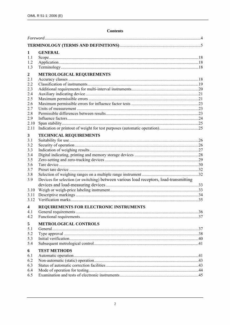
For instruments fitted with an auxiliary indicating device such as an indicating device with a differentiated scale division (Figure 1), the device is permitted only to the right of the decimal sign.
Figure 1 – Examples of indicating devices each with a differentiated scale division
523.4
g Last differentiated figure: 5 d = 0.01 g or 0.05 g e = 0.1 g
823.4
g Last differentiated figure: 8 d = 0.01 g or 0.02 g e = 0.1 g
For category Y(a) and Y(b) instruments, the use of auxiliary indicating devices shall be limited to testing applications only.
A multi-interval instrument shall not be fitted with an auxiliary indicating device.
Note: Extended indicating devices (see T.2.9.2 and 3.4.2) are not regarded as auxiliary indicating devices.
2.5 Maximum permissible errors
2.5.1 Automatic operation
2.5.1.1 Category X instruments
For a number of consecutive weighings of a net load, greater than or equal to the minimum capacity, Min, and less than or equal to the maximum capacity, Max, the maximum permissible mean (systematic) error shall be as specified in Table 3.
Table 3
Net load, m, expressed in verification scale intervals, e
Maximum permissible mean error for
category X instruments
XI XII XIII XIIII Initial verification
In-service inspection
0 < m ≤ 50 000 0 < m ≤ 5 000 0 < m ≤ 500 0 < m ≤ 50 ±0.5 e ±1 e
50 000 < m ≤ 200 000 5 000 < m ≤ 20 000 500 < m ≤ 2 000 50 < m ≤ 200 ±1 e ±2 e
200 000 < m 20 000 < m ≤ 100 000 2 000 < m ≤ 10 000 200 < m ≤ 1 000 ±1.5 e ±3 e
The maximum permissible standard deviation of the error (random error) shall be as specified in Table 4, multiplied by the class designation factor (x).

OIML R 51-1: 2006 (E)
22
Table 4
Maximum permissible standard deviation (as a percentage of m or in grams) for class designation factor, (x) = 1
Value of the mass of the net load, m
(g) Initial verification In-service inspection m ≤ 50 0.48 % 0.6 % 50 < m ≤ 100 0.24 g 0.3 g 100 < m ≤ 200 0.24 % 0.3 % 200 < m ≤ 300 0.48 g 0.6 g 300 < m ≤ 500 0.16 % 0.2 % 500 < m ≤ 1 000 0.8 g 1.0 g 1 000 < m ≤ 10 000 0.08 % 0.1 % 10 000 < m ≤ 15 000 8 g 10 g
15 000 < m 0.053 % 0.067 %
For classes XI and XII, (x) shall be less than 1; For class XIII, (x) shall be not greater than 1; For class XIIII, (x) shall be greater than 1.
2.5.1.2 Category Y instruments
The maximum permissible error for any load greater than or equal to the Min and less than or equal to the Max in automatic operation shall be as specified in Table 5.
Table 5
Load, m, expressed in verification scale intervals, e
Maximum permissible error for category Y
instruments*
Y(I) Y(II) Y(a) Y(b) Initial verification
In-service inspection
0 < m ≤ 50 000 0 < m ≤ 5 000 0 < m ≤ 500 0 < m ≤ 50 ±1 e ±1.5 e
50 000 < m ≤ 200 000 5 000 < m ≤ 20 000 500 < m ≤ 2 000 50 < m ≤ 200 ±1.5 e ±2.5 e
200 000 < m 20 000 < m ≤ 100 000 2 000 < m ≤ 10 000 200 < m ≤ 1 000 ±2 e ±3.5 e
* This MPE is applicable for instruments with a device for displaying the digital indication with d ≤ 0.2 e. (see A.3.9.2.1). For instruments without a device for displaying the indication with d ≤ 0.2 e the procedure in A.3.9.2.2 shall be applied.
If the net weight value is calculated by subtraction of two individual weighings, the MPEs only apply: to these individual weighings if they are printed or recorded separately; or to the net weight value if only the net weight value is printed.
2.5.2 Non-automatic (static) operation
Note: This clause concerns the mode defined in T.3.4.3 and is therefore not applicable for the automatic (static) weighing mode.
For category X and category Y instruments, the maximum permissible error for any load greater than or equal to the Min and less than or equal to the Max in non-automatic (static) operation shall be as specified in Table 6.
OIML R 51-1: 2006 (E)
23
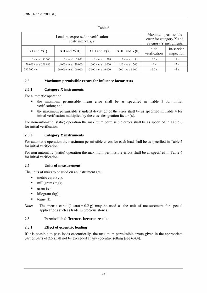
Table 6
Load, m, expressed in verification scale intervals, e
Maximum permissible error for category X and category Y instruments
XI and Y(I) XII and Y(II) XIII and Y(a) XIIII and Y(b) Initial verification
In-service inspection
0 < m ≤ 50 000 0 < m ≤ 5 000 0 < m ≤ 500 0 < m ≤ 50 ±0.5 e ±1 e
50 000 < m ≤ 200 000 5 000 < m ≤ 20 000 500 < m ≤ 2 000 50 < m ≤ 200 ±1 e ±2 e
200 000 < m 20 000 < m ≤ 100 000 2 000 < m ≤ 10 000 200 < m ≤ 1 000 ±1.5 e ±3 e
2.6 Maximum permissible errors for influence factor tests
2.6.1 Category X instruments
For automatic operation: the maximum permissible mean error shall be as specified in Table 3 for initial
verification; and the maximum permissible standard deviation of the error shall be as specified in Table 4 for
initial verification multiplied by the class designation factor (x).
For non-automatic (static) operation the maximum permissible errors shall be as specified in Table 6 for initial verification.
2.6.2 Category Y instruments
For automatic operation the maximum permissible errors for each load shall be as specified in Table 5 for initial verification.
For non-automatic (static) operation the maximum permissible errors shall be as specified in Table 6 for initial verification.
2.7 Units of measurement
The units of mass to be used on an instrument are: metric carat (ct); milligram (mg); gram (g); kilogram (kg); tonne (t).
Note: The metric carat (1 carat = 0.2 g) may be used as the unit of measurement for special applications such as trade in precious stones.
2.8 Permissible differences between results
2.8.1 Effect of eccentric loading
If it is possible to pass loads eccentrically, the maximum permissible errors given in the appropriate part or parts of 2.5 shall not be exceeded at any eccentric setting (see 6.4.4).

OIML R 51-1: 2006 (E)
24
2.8.2 Agreement between indicating and printing devices
For the same load, the difference between the weighing results (T.3.2) provided by any two devices having the same scale interval shall be as follows:
zero for digital displaying and printing devices; not greater than the absolute value of the maximum permissible error for automatic weighing
for analog devices.
2.9 Influence factors
Refer to Annex A for test conditions.
2.9.1 Temperature
2.9.1.1 Temperature limits
If no particular working temperature is stated in the descriptive markings of an instrument, this instrument shall maintain its metrological properties within the following temperature limits:
–10 °C to +40 °C
2.9.1.2 Special temperature limits
An instrument for which particular limits of working temperature are stated in the descriptive markings shall comply with the metrological requirements within those limits. The limits may be chosen according to the application of the instrument.
The ranges within those limits shall be at least equal to: 5 °C for instruments of classes XI and Y(I); 15 °C for instruments of classes XII and Y(II); 30 °C for instruments of all other classes.
2.9.1.3 Temperature effect on no-load indication
The indication at zero or near zero shall not vary by more than one verification scale interval for a difference in ambient temperature of 1 °C for instruments of classes XI and Y(I), and 5 °C for other classes.
2.9.2 Voltage supply
An electronic instrument shall comply with the appropriate metrological and technical requirements, if the voltage supply varies from the nominal voltage, Unom (if only one voltage is marked on the instrument), or from the lower and upper limits of the voltage range, Umin and Umax, marked on the instrument at:
AC mains voltage: - lower limit is 85 % of Umin, - upper limit is 110 % of Umax;
DC mains voltage, including rechargeable battery if the battery can be fully (re)charged during the operation of the instrument:
- lower limit is the minimum operating voltage, - upper limit is 120 % of Umax (Umax is the voltage of a new or fully charged
rechargeable battery of the type specified by the manufacturer);

OIML R 51-1: 2006 (E)
25
DC battery supply, including non-rechargeable battery supply, and also including
rechargeable battery supply if the batteries cannot be (re)charged during operation of the instrument:
- lower limit is the minimum operating voltage, - upper limit is Unom;
12 V or 24 V road vehicle battery supply: - lower limit is 9 V (for a 12 V battery) or 16 V (for a 24 V battery), - upper limit is 16 V (for a 12 V battery) or 32 V (for a 24 V battery).
Note: The minimum operating voltage is defined as the lowest possible operating voltage before the instrument is automatically switched off.
Battery-operated and DC mains powered instruments shall either continue to function correctly or not indicate any weight values if the voltage is below the manufacturer’s specified value, the latter being larger or equal to the minimum operating voltage.
2.9.3 Tilting
Instruments which are not intended for installation in a fixed position and which do not have a leveling device and a level indicator shall comply with the appropriate metrological and technical requirements when tilted (longitudinally and transversely) by 5 %, or when tilted to a predetermined value selected by the manufacturer if the instrument is provided with a tilt limiting device which prevents the instrument from operating when tilted above this value.
Where a leveling device and a level indicator are present they shall enable the instrument to be set to a tilt of 1 % or to the limiting value of tilting as defined by an obvious marking on the level indicator, (e.g. a ring, or a legible notice provided on the instrument in a clearly visible place that points the user to the level indicator). The level indicator shall be fixed firmly on the instrument in a place clearly visible to the user and representative for the tilt sensitive part.
Instruments mounted on or incorporated in vehicles shall comply with the appropriate metrological and technical requirements when tilted (longitudinally and transversely) by 10 %, or when tilted to a lower predetermined value selected by the manufacturer, e.g. 3 %, if the instrument is provided with an automatic tilt limiting device which prevents the instrument from operating when tilted above this value.
2.10 Span stability
When the instrument is subjected to the span stability test specified in A.7, the absolute value of the difference between the errors obtained for any two measurements shall not exceed the maximum span error.
The maximum span error is equal to half the maximum permissible error for influence factor tests for a near maximum capacity load.
2.11 Indication or printout for test purposes (automatic operation)
For category X instruments, practical means shall be provided in accordance with 6.1.8 for determining the mean error and the standard deviation of the error to demonstrate compliance with Tables 3 and 4, e.g. indications and/or print-outs of the mass (or the difference between the mass and a nominal set-point).
Note: In normal operation, the sorting device of category X instruments shall work with the same or smaller scale interval, d, which is used for determining the mean error and standard deviation of the error during type approval and initial verification testing.
For category Y instruments, practical means for determining the individual errors of weighings shall be provided in accordance with 6.1.7.2 to demonstrate compliance with Table 5.

OIML R 51-1: 2006 (E)
26
3 TECHNICAL REQUIREMENTS
3.1 Suitability for use
An instrument shall be designed to suit the method of operation and the loads for which it is intended. It shall be of adequately robust construction to ensure that it maintains its metrological characteristics.
3.2 Security of operation
3.2.1 Fraudulent use
An instrument shall have no characteristics likely to facilitate its fraudulent use.
3.2.2 Accidental breakdown and maladjustment
An instrument shall be so constructed that an accidental breakdown or maladjustment of control elements likely to disturb its correct functioning cannot take place without its effect being evident.
3.2.3 Dynamic setting
An instrument may be fitted with a dynamic setting facility to compensate for the dynamic effects of the load in motion. This facility may operate over a weighing range relative to a setting weight value provided that when the facility is used for that weighing range and in accordance with the manufacturer’s instructions, the maximum permissible errors are not exceeded.
Once dynamic setting has taken place to give a weighing range over which the permissible errors are not exceeded, the instrument shall automatically take appropriate action for loads falling outside that range; for these loads, printout of the weight shall also be inhibited.
Instruments with dynamic setting available to the user (not secured in accordance with 3.2.6) shall have a facility to automatically and non-erasably record any adjustment of the dynamic setting, e.g. an event logger. The instrument shall be capable of presenting the recorded data.
3.2.4 Controls
Controls shall be so designed that they cannot normally come to rest in positions other than those intended by design, unless during the manoeuvre all indication is made impossible. Keys shall be marked unambiguously.
3.2.5 Tilt limiting device
An instrument mounted on a vehicle may be provided with a tilt limiting device which prevents the instrument from operating if the vehicle is tilted (longitudinally and transversely) above a predetermined value set by the manufacturer.
3.2.6 Securing
Means shall be provided for securing components, interfaces, device-specific parameters and preset controls to which access or adjustment is prohibited. National regulations may specify the securing that is required. On classes XI and Y(I) instruments, devices to adjust sensitivity (or span) may remain unsecured.
The introduction into the instrument of data that can influence the instrument’s metrological properties or measurement results shall be prevented, e.g. by a protective interface (4.2.4).
Components and preset controls may be secured by passwords or similar software means provided that any access to the secured controls or functions becomes automatically evident, e.g. by automatically updating a device-specific parameter the value of which at the time of the last verified setup had been durably marked on the instrument in accordance with the requirements of 3.11.4.

OIML R 51-1: 2006 (E)
27
An instrument may be fitted with a span adjustment device. External influence upon this device shall be practically impossible after securing.
3.2.7 Sorting device
The sorting device of a category X instrument shall automatically divide loads into separate sub-groups depending on their mass.
3.3 Indication of weighing results
3.3.1 Quality of reading
Reading of the primary indications (T.1.10.1) shall be reliable, easy and unambiguous under conditions of normal use:
the overall inaccuracy of reading of an analog indicating device shall not exceed 0.2 e; the figures, units and designations forming the primary indications shall be of a size, shape
and clarity for reading to be easy.
The scales, numbering and printing shall permit the figures which form the results to be read by simple juxtaposition (see T.4.2.1).
3.3.2 Form of the indication
Weighing results shall contain the names or symbols of the units of mass in which they are expressed.
For any one indication of weight value, only one unit of mass may be used.
The scale interval for weighing results (T.3.2) shall be in the form 1 × 10k, 2 × 10k or 5 × 10k units in which the result is expressed, k being a positive or negative whole number or zero.
All indicating, printing and tare weighing devices of an instrument shall, within any one weighing range, have the same scale interval for any given load.
A digital indication shall display at least one figure beginning at the extreme right.
A decimal fraction shall be separated from its integer by a decimal sign (comma or dot), with the indication showing at least one figure to the left of the sign and all figures to the right.
Zero may be indicated by one zero to the extreme right, without a decimal sign.
The unit of mass shall be chosen so that the weight values have not more than one non-significant zero to the right. For values with a decimal sign, the non-significant zero is allowed only in the third position after the decimal sign. The units of mass shall be written in small letters (lower case) as indicated in 2.7.
3.3.3 Limits of indication
Category Y: There shall be no indication, printing, storing or transmission of weight values above Max + 9 e.
Category X: There shall be no indication, printing, storing or transmission of weight values above Max + 9 e or Max + three times the maximum permissible standard deviation value as specified in Table 4, whichever is the greater.
3.3.4 Indication or printout for normal operation
For normal operation the scale interval of indications or printouts of individual article weights shall be the verification scale interval, e.

OIML R 51-1: 2006 (E)
28
The scale interval of indications or printouts of the mean (systematic) error and the standard deviation of the error (or indication), for a number of consecutive automatic weighings of a load, may be to a higher resolution than the verification scale interval, e.
3.4 Digital indicating, printing and memory storage devices
The following requirements apply in addition to those in 3.3.1-3.3.4.
3.4.1 Stable equilibrium (T.3.2.5)
For instruments that weigh statically, equilibrium is deemed to be stable when: in the case of printing and/or data storage, the printed or stored weighing values show no more
than two adjacent values, one of them being the final weight value (T.3.2.4.3); and in the case of zero or tare operations, a correct operation according to 3.4.3 (printing), 3.5.3
(control of zero-setting), 3.5.4 (stability of automatic zero-setting), 3.5.5 (zero-tracking) and 3.6.7 (tare-weighing) of the device within relevant accuracy requirements is achieved.
Both conditions shall also be met under continuous or temporary disturbance of the equilibrium.
For instruments that weigh dynamically, no separate criteria for stable equilibrium are given.
3.4.2 Extended indicating device
An extended indicating device shall not be used on an instrument with an auxiliary indicating device.
When an instrument is fitted with an extended indicating device, displaying the indication with a scale interval smaller than e shall be possible only:
whilst a particular key is pressed; or for a period not exceeding 5 seconds after a manual command.
In any case printing shall not be possible.
3.4.3 Printing device
Printing shall be clear and permanent for the intended use. Printed figures shall be at least 2 mm high.
If printing takes place, the name or the symbol of the unit of measurement shall be either to the right of the value or above a column of values.
Printing shall be inhibited if the stability criteria (3.4.1) are not fulfilled.
3.4.4 Data storage device (T.2.7.8.5)
The primary indications may be stored in a memory of the instrument or on external storage for subsequent use (e.g. indication, printing, data transfer, totalizing, etc.). In this case, the stored data shall be adequately protected against intentional and unintentional changes during the data transmission and/or storage process and shall contain all relevant information necessary to reconstruct an earlier measurement.
The storage of primary indications shall be inhibited if the stability criteria (3.4.1) are not fulfilled.
3.4.5 Software
The legally relevant software used in the instrument must be present in such a form that alteration of the software is not possible without breaking a seal, or any change in the software can be signaled automatically by means of an identification code.
The legally relevant software shall be adequately protected against accidental or intentional changes. Evidence of an intervention such as changing, uploading or circumventing the legally relevant software shall be available until the next verification or comparable official inspection.

OIML R 51-1: 2006 (E)
29
The software shall be assigned a fixed software identification (T.2.7.8.4). This fixed software identification shall be adapted in the case of every software change that may affect the metrological functions of the instrument.
Software documentation provided with the instrument shall include the following: a) A description of the system hardware, e.g. topology block diagram, type of computer(s),
source code for software functions, etc. and legally relevant software environment; b) A description of the fixed software version number and/or software identification) that is
assigned to the metrologically relevant functions; c) A description of the relevant menus and dialogues; d) The securing measures foreseen (e.g. checksum, signature, audit trail); e) A description of the data storage device(s); f) The operating manual.
3.5 Zero-setting and zero-tracking devices
An instrument shall have one or more zero-setting devices and shall not have more than one zero-tracking device. These devices may be:
non-automatic; semi-automatic; or automatic.
3.5.1 Maximum effect
The effect of any zero-setting device shall not alter the maximum weighing capacity of the instrument.
The overall effect of zero-setting and zero-tracking devices shall not be more than 4 %, and of the initial zero-setting device not more than 20 %, of the maximum capacity.
A wider range is possible for the initial zero-setting device if tests show that the instrument complies with the maximum permissible errors in 2.5 and 2.6, the permissible differences in errors in 2.8, and the influence factors in 2.9, for any load compensated by this device within the specified range.
3.5.2 Accuracy
After zero-setting the effect of zero deviation on the result of the weighing shall be not more than 0.25 e.
3.5.3 Control of the zero-setting devices
An instrument, whether or not equipped with an initial zero-setting device, may have a combined semi-automatic zero-setting and semi-automatic tare-balancing device operated by the same key.
If an instrument has a zero-setting device and a tare-weighing device, the control of the zero-setting device shall be separate from that of the tare-weighing device.
A semi-automatic zero-setting device shall function only: when the instrument is in stable equilibrium (3.4.1); if it cancels any previous tare operation.
A non-automatic or semi-automatic zero-setting device shall not be operable during automatic operation.
3.5.4 Stability of automatic zero-setting device
An automatic zero-setting device may operate at the start of automatic operation, as part of every automatic weighing cycle, or after a programmable time interval. A description of the operation of the

OIML R 51-1: 2006 (E)
30
automatic zero-setting device (e.g. the maximum programmable time interval) shall be included in the type approval certificate.
The automatic zero-setting device shall operate: only when the stability criteria (3.4.1) are fulfilled; and sufficiently often to ensure that zero is maintained within 0.5 e.
Where the automatic zero-setting device operates as part of every automatic weighing cycle, it shall not be possible to disable this device or to set it to operate at time intervals.
Where the automatic zero-setting device operates after a programmable time interval, the manufacturer shall specify the maximum time interval. The maximum programmable time interval shall not be greater than the value necessary to ensure that the zero error is not greater than 0.5 e (see A.5.5).
The maximum programmable time interval for automatic zero-setting required above may start again after tare weighing or zero tracking has taken place.
The actual maximum programmable time interval for automatic zero-setting shall be specified taking into account the actual operating conditions of the instrument. The automatic zero-setting device shall either automatically set to zero after the allocated time or shall stop the instrument so that a zero-setting operation can occur or be capable of generating information to draw attention to overdue zero-setting.
3.5.5 Zero-tracking device
A zero-tracking device shall operate only when: the indication is at zero, or at a negative net value (T.3.2.2) equivalent to gross zero; the stability criteria (3.4.1) are fulfilled; and the corrections are not more than 0.5 e/second.
When zero is indicated after a tare operation, the zero-tracking device may operate within a range of 4 % of Max around the actual zero.
Note: Zero-tracking is functionally similar to automatic zero-setting. The differences are important in applying the requirements of 3.5. Refer to T.2.10.8.3 and T.2.10.9. For many types of catchweigher, which have automatic zero-setting, zero-tracking will not be appropriate. The maximum rate of correction applicable to zero-tracking does not apply to zero-setting.
Automatic zero-setting is activated by an event, such as part of every automatic weighing cycle or after a programmed interval;
Zero-tracking may operate continuously (when the conditions of 3.5.5 are fulfilled) and must therefore be subject to a maximum rate of correction (0.5 e/second) to prevent interaction with the normal weighing process.
3.6 Tare device
3.6.1 Scale interval
The scale interval of the tare device shall be equal to the scale interval of the instrument for any given load.
3.6.2 Accuracy
A tare device shall permit setting the indication to zero with a deviation of not more than 0.25 e.
On a multi-interval instrument, e shall be replaced by e1.

OIML R 51-1: 2006 (E)
31
3.6.3 Operating range
The tare device shall be such that it cannot be used at or below its zero effect or above its maximum indicated effect.
3.6.4 Visibility of operation
Operation of the tare device shall be visibly indicated on the instrument. In the case of instruments with digital indication this shall be done by marking the indicated net value (T.3.2.2) with the sign “NET” or “N”, and if applicable, the indicated tare value (T.3.2.3) with the sign “T”.
Note 1: “NET” may also be displayed as “Net” or “net”.
Note 2: If an instrument is equipped with a device that allows the gross value (T.3.2.1) to be displayed temporarily while a tare device is in operation, the “NET” symbol shall disappear while the gross value is displayed.
This is not required for an instrument with a combined semi-automatic zero-setting device and a semi-automatic tare-balancing device operated by the same key.
It is permitted to replace the symbols “NET” and “T” by complete words in an official language of the country where the instrument is used.
3.6.5 Subtractive tare device
When the use of a subtractive tare device does not allow the value of the residual weighing range to be known, a device shall prevent the use of the instrument above its maximum capacity or indicate that this capacity has been reached.
3.6.6 Multiple range instrument
On a multiple range instrument the tare operation shall be effective also in the greater weighing ranges, if switching to a greater weighing range is possible while the instrument is loaded.
3.6.7 Operation of tare devices
Semi-automatic or automatic tare devices shall operate only when the stability criteria (3.4.1) are fulfilled.
A non-automatic or semi-automatic tare device shall not be operable during automatic operation.
3.6.8 Combined zero-setting and tare-balancing devices
If the semi-automatic zero-setting device and the semi-automatic tare-balancing device are operated by the same key, 3.5.2 (zero-setting accuracy) and if appropriate 3.6.2 (tare setting accuracy), apply at any load.
3.6.9 Consecutive tare operations
Repeated operation of a tare device is permitted.
If more than one tare device is operative at the same time, tare weight values shall be clearly designated when indicated or printed.
3.6.10 Printing of weighing results
Gross weight values (T.3.2.1) may be printed without any designation. For a designation by a symbol, only “G” or “B” are permitted.
If only net values (T.3.2.2) are printed without corresponding gross or tare values, they may be printed without any designation. A symbol for designation shall be “N”. These conditions apply also where semi-automatic zero-setting and semi-automatic tare balancing are initiated by the same key.

OIML R 51-1: 2006 (E)
32
Gross, net, or tare values determined by a multiple range instrument or a multi-interval instrument need not be marked by a special designation referring to the (partial) weighing range.
If net values are printed together with the corresponding gross and/or tare values, the net and tare values shall at least be identified by the corresponding symbols “N” and “T”.
However, it is permitted to replace the symbols G, B, N and T by complete words in an official language of the country in which the instrument is used.
If net values and tare values determined by different tare devices are printed separately, they shall be suitably identified.
3.7 Preset tare device
3.7.1 Scale interval
For Category X instruments the preset tare scale interval, dT, shall be equal to or smaller than the verification scale interval, e, of the instrument.
For Category Y instruments the preset tare scale interval, dT, shall be equal to or automatically rounded to the scale interval, d, of the instrument.
On a multiple range instrument a preset tare value (T.3.2.4.1) may only be transferred from one weighing range to another one with a larger verification scale interval but shall then be rounded to the latter. For a multi-interval instrument, the preset tare value shall be entered with the smallest verification scale interval, e1, of the instrument, and the maximum preset tare value shall not be greater than Max1. The indicated or printed calculated net value (T.3.2.4.2) shall be rounded to the scale interval of the instrument for the same net weight value.
3.7.2 Modes of operation
A preset tare device may be operated together with one or more tare devices provided that: 3.6.9 (consecutive tare operations) is respected; and a preset tare operation cannot be modified or cancelled as long as any tare device operated
after the preset tare operation is still in use.
Preset tare devices may operate automatically only if the preset tare value is clearly identified with the load to be measured (e.g. by bar code identification on the container).
3.7.3 Indication of operation
For the indicating device 3.6.4 (visibility of operation) applies. It shall be possible to indicate the preset tare value at least temporarily.
3.6.10 applies accordingly provided that: if the calculated net value is printed at least the preset tare value is printed as well; preset tare values are designated by the symbol “PT”; however, it is permitted to replace the
symbol “PT” by complete words in an official language of the country in which the instrument is used.
3.8 Selection of weighing ranges on a multiple range instrument
The range that is actually in operation shall be clearly indicated.

OIML R 51-1: 2006 (E)
33
3.8.1 Manual selection
Manual selection of the weighing range is allowed: from a smaller to a greater weighing range, at any load; from a greater to a smaller weighing range, when there is no load on the load receptor, and the
indication is zero or at a negative net value; the tare operation shall be cancelled, and zero shall be set to ±0.25 e1, both automatically.
Manual selection of the weighing range shall be inhibited during automatic operation.
3.8.2 Automatic selection
Automatic change over is allowed: from a smaller to the following greater weighing range when the load exceeds the maximum
gross weight value of the range being operative; only from a greater to the smallest weighing range when there is no load on the load receptor,
and the indication is zero or at a negative net value; the tare operation shall be cancelled and zero shall be set to ±0.25 e1, both automatically.
3.9 Devices for selection (or switching) between various load receptors, load-transmitting devices and load-measuring devices
3.9.1 Compensation of no-load effect
The selection device shall ensure compensation for the unequal no-load effect of the various load receptors and/or load-transmitting devices in use.
3.9.2 Zero-setting
Zero-setting of an instrument with any multiple combination of various load-measuring devices and various load receptors shall be possible without ambiguity and in accordance with the provisions of 3.5.
3.9.3 Impossibility of weighing
Weighing shall not be possible while selection devices are being used.
3.9.4 Identification of the combinations used
Combinations of load receptors and load-measuring devices used shall be readily identifiable.
3.10 Weigh or weigh-price labeling instrument
A weigh or weigh-price labeling instrument shall have at least one displaying device for the weight value. It may be used temporarily for setup purposes such as supervision of weight value setting limits, unit prices, preset tare values and commodity names.
It shall be possible to verify the actual values of unit price and preset tare during automatic operation.
3.10.1 Price computing
The price to pay shall be calculated and rounded to the nearest interval of price to pay by multiplication of weight value and unit price, both as indicated or printed by the instrument. The device which performs the calculation is considered a part of the instrument.
The interval of price to pay, and the monetary symbols and location shall comply with national regulations applicable to trade.

OIML R 51-1: 2006 (E)
34
The unit price shall be in the form of: Price/100 g or Price/kg, or specified in accordance with national regulations applicable to trade.
3.10.2 Totalization
An instrument may totalize weight values and price data on one or more tickets or labels provided that the total values are identified by a special word or symbol. All totals shall be the algebraic sums of all the values printed.
3.10.3 Printing
When price computing transactions performed by the instrument are printed, the weight value, unit price and price to pay shall all be printed.
The data may be stored in a memory of the instrument before printing. The same data shall not be printed twice on the ticket or label.
Printing below minimum capacity shall not be possible.
3.11 Descriptive markings
Instruments and associated modules shall bear the following markings, variable according to national regulation, at each location having a mass indicating and/or printing device.
3.11.1 Markings shown in full
name or identification mark of the manufacturer name or identification mark of the importer (if applicable) serial number and type designation of the instrument maximum rate of operation (if applicable) in the form: ..... loads/min or units/min maximum speed of load transport system (if applicable)
in the form: ..... m/s or m/min electrical supply voltage in the form: ..... V electrical supply frequency in the form: ..... Hz pneumatic/hydraulic pressure (if applicable) in the form: ..... kPa adjustment range referred to set point (if applicable)
in the form: ±..... g or % (of set point value) temperature range (when not –10 °C to +40 °C) software identification (if applicable)
3.11.2 Markings shown in code
type approval sign indication of the accuracy class, e.g. XI(0.5) or Y(a) verification scale interval in the form: e = ..... actual scale interval in the form: d = ..... maximum capacity in the form: Max ..... minimum capacity in the form: Min ..... maximum additive tare in the form: T = +..... maximum subtractive tare in the form: T = –.....

OIML R 51-1: 2006 (E)
35
3.11.3 Supplementary markings
Depending upon the particular use of the instrument, supplementary markings may be required on type approval by the metrological authority issuing the type approval certificate (for example: securing code, date of manufacture).
Additional markings (for example, products) may be required on initial verification to specify types of packs and related weighing conditions.
3.11.4 Presentation of descriptive markings
Descriptive markings shall be indelible and of a size, shape and clarity that permit legibility under normal conditions of use.
Descriptive markings may be either in the national language or in form of adequate, internationally agreed and published pictograms or signs.
They shall be grouped together in a clearly visible place on the instrument, either on a descriptive plate or sticker fixed permanently to the instrument, or on a non removable part of the instrument itself. In the case of a plate or sticker which is not destroyed when removed, a means of securing shall be provided, e.g. a non removable control mark that can be applied.
It shall be possible to seal the plate bearing the markings, unless it cannot be removed without being destroyed.
Alternatively, the descriptive markings may be simultaneously shown on a display which is controlled by software either permanently or on manual command provided that:
the markings: Max…, Min…, e, d if d ≠ e, and X(x) and/or Y(y) shall be shown at least in one place and permanently either on the display or near to the display in a clearly visible position, and are permanently and simultaneously shown (or alternating one after each other) on the display of the weighing result as long as the instrument is switched on;
the other markings may be shown on manual command; the markings are considered as device-specific parameters (see T.2.7.8.3) and shall comply
with the requirements for securing in 3.2.6.
When a software controlled display is used, the plate of the instrument shall bear at least the following markings:
max, min and d shall be shown near the display if not already located there; type approval sign in accordance with national requirements; name or identification mark of the manufacturer/ type/ serial number; electrical supply voltage; electrical supply frequency; pneumatic/ hydraulic pressure.
3.12 Verification marks
3.12.1 Position
Instruments shall have a place for the application of verification marks. This place shall: be such that the part on which it is located cannot be removed from the instrument without
damaging the marks; allow easy application of the mark without changing the metrological qualities of the
instrument; normally be visible without the instrument having to be moved when it is in service.

OIML R 51-1: 2006 (E)
36
3.12.2 Mounting
Instruments required to bear verification marks shall have a verification mark support, at the place provided for above, which shall ensure the conservation of the marks. The type and method of sealing shall be determined by national prescription.
4 REQUIREMENTS FOR ELECTRONIC INSTRUMENTS Electronic instruments shall comply with the following requirements, in addition to the applicable requirements of all other clauses of this Recommendation.
4.1 General requirements
4.1.1 Rated operated conditions
Electronic weighing instruments shall be so designed and manufactured that they do not exceed the maximum permissible errors under rated operating conditions.
4.1.2 Influence factors
An electronic instrument shall comply with the requirements of 2.9 and shall also comply with appropriate metrological and technical requirements at a relative humidity of 85 % at the upper limit of the temperature range.
Note: This is not applicable to an electronic instrument of classes XI and Y(I), and of classes XII and Y(II) if e is less than 1 g.
4.1.3 Disturbances
Electronic instruments shall be so designed and manufactured that when exposed to disturbances, either:
a) significant faults do not occur, i.e. the difference between the weight value indication due to the disturbance and the indication without the disturbance (intrinsic error) does not exceed 1 e; or
b) significant faults are detected and acted upon. The indication of significant faults in the display should not be confusing with other messages that appear in the display.
Note: A fault equal to or less than the value specified in T.4.3.9 (1 e) is allowed irrespective of the value of the error of indication.
4.1.4 Durability
The requirements in 4.1.1, 4.1.2 and 4.1.3 shall be met durably in accordance with the intended use of the instrument.
4.1.5 Evaluation for compliance
A type of an electronic instrument is presumed to comply with the requirements of 4.1.1, 4.1.2 and 4.1.3 if it passes the examination and tests specified in Annex A.
4.1.6 Application
The requirements for disturbances in 4.1.3 may be applied separately to: each individual cause of significant fault; and/or each part of the electronic instrument.
The choice of whether 4.1.3 a) or b) is applied is left to the manufacturer.
OIML R 51-1: 2006 (E)
37
4.2 Functional requirements
4.2.1 Indications test
If the failure of an indicator can cause a false weight value indication then the instrument shall have a display test facility which is automatically initiated at switch-on of indication, e.g. display of all the relevant signs of the indicator in their active and non-active states for a sufficient time to be easily observed by the operator. This is not applicable for non-segmented displays, on which failures become evident, for example screen-displays, matrix-displays, etc.
4.2.2 Acting upon a significant fault
When a significant fault has been detected, the instrument shall either be made inoperative automatically or a visual or audible indication shall be provided automatically and shall continue until such time as the user takes action or the fault disappears.
4.2.3 Warm-up time
During the warm-up time of an electronic instrument there shall be no indication or transmission of the result of weighing, and automatic operation shall be inhibited.
4.2.4 Interfaces
An electronic instrument may be equipped with interfaces permitting the coupling of the instrument to any peripheral devices or other instruments.
An interface shall not allow the metrological functions of the instrument and its measurement data to be inadmissibly influenced by the peripheral devices (for example computers), by other interconnected instruments, or by disturbances acting on the interface.
Functions that are performed or initiated via an interface shall meet the relevant requirements and conditions of clause 3.
Note: An “interface” comprises all mechanical, electrical and software devices at the data interchange point between an instrument and peripheral devices or other instruments.
It shall not be possible to introduce into an instrument, through an interface, instructions, software programs or data intended or suitable to:
display data that are not clearly defined and could be mistaken for a weighing result; falsify displayed, processed or stored weighing results; adjust the instrument or change any adjustment factor.
An interface through which the functions mentioned above cannot be performed or initiated, need not be secured. Other interfaces shall be secured as described in 3.2.6.
An interface intended to be connected to a peripheral device to which the requirements of this Recommendation apply, shall transmit data relating to primary indications in such a manner that the peripheral device can meet the requirements.
5 METROLOGICAL CONTROLS
5.1 General
The metrological controls of instruments shall, in agreement with national regulation, consist of: type approval; initial verification; subsequent verification; in-service inspection.

OIML R 51-1: 2006 (E)
38
Tests should be applied uniformly by the legal metrology services and should form a uniform program. Guidance for the conduct of type approval and initial verification is provided in OIML International Documents D 19 [8] and D 20 [9] respectively.
5.2 Type approval
5.2.1 Documentation
The application for type approval shall include documentation comprising: metrological characteristics of the instrument; a set of specifications for the instrument; a functional description of the components and devices; drawings, diagrams and general software information (if applicable), explaining the
construction and operation; and any document or other evidence that the design and construction of the instrument complies
with the requirements of this Recommendation.
Note: Adherence to requirements for which no test is available, such as software-based operations, may be demonstrated by a specific declaration of the manufacturer (e.g. for interfaces as described in 4.2.4, and for password protected access to device-specific parameters, and setup and adjustment operations as described in 3.2.6).
5.2.2 General requirements
Type evaluation shall be carried out on one or more and not normally more than three instruments that represent the definitive type. If the performance of an instrument could be affected by a particular manner of operation or a particular manner of use for which conditions cannot be duplicated other than in an in-situ operation then at least one of the instruments shall be completely installed at a typical site. At least one of the instruments shall be submitted in a form suitable for laboratory simulation tests. The evaluation shall consist of the tests specified in 5.2.3.
5.2.3 Type evaluation
The submitted documents shall be examined and tests carried out to verify that the instruments comply with:
the metrological requirements in clause 2, particularly with reference to maximum permissible errors on initial verification referred to in 2.5 using test loads described in 6.1.3.1 or test loads specified by the manufacturer;
the technical requirements in clause 3; the requirements in clause 4 for electronic instruments, where applicable.
The metrological authority shall: conduct the tests in a manner that prevents an unnecessary commitment of resources; permit the results of these tests to be assessed for initial verification when the same instrument
is involved; check that an instrument used in non-automatic (static) operation in accordance with 2.5.2,
meets the weighing performance test requirements of OIML R 76-1 [10].
5.2.3.1 Operational tests
Tests shall be done as follows: in accordance with the descriptive markings (3.11); under the normal conditions of use for which the instrument is intended; and in accordance with the test methods in clause 6.

OIML R 51-1: 2006 (E)
39
The metrological authority may require the applicant to supply test loads, equipment and personnel to perform the tests.
The metrological authority may accept, with the consent of the applicant, test data obtained from other metrological authorities without repeating the tests.
Accuracy requirements shall be applied in accordance with the appropriate parts of clause 2.
5.2.3.2 Tests and checks for compliance with technical requirements
Tests and checks shall be done on a complete instrument to assess compliance with the requirements for security of operation in 3.2.
5.2.3.3 Influence factor tests
Influence factors shall be applied to the complete instrument or simulator as specified in 6.4.5 and in Annex A, in accordance with:
2.9 for all instruments; clause 4 for electronic instruments.
5.2.3.4 Apportioning of errors
Where modules of an instrument or system are tested separately the following requirements apply.
The error limits applicable to a module which is examined separately are equal to a fraction pi of the maximum permissible errors or the allowed variations of the indication of the complete instrument as specified in 2.5. The fractions for any module have to be taken for at least the same accuracy class as for the complete instrument incorporating the module.
The fractions pi shall satisfy the following equation:
p12 + p2
2 + p32 +... ≤ 1
The fraction pi shall be chosen by the manufacturer of the module and shall be verified by an appropriate test, taking into account the following conditions:
for digital devices pi may be equal to 0;
for weighing modules pi may be equal to 1;
for all other modules (including digital load cells), pi shall not exceed 0.8 and shall not be less than 0.3, when more than one module contributes to the effect in question.
If the metrological characteristics of the load cell or other modules have been evaluated in accordance with the requirements of OIML R 60 [6], or any other applicable OIML Recommendation, that evaluation shall be used to aid type evaluation if so requested by the applicant.
5.2.4 Place of testing
Instruments submitted for type approval may be tested either: on the premises of the metrological authority to which the application has been submitted; or in any other suitable place agreed between the metrological authority concerned and the
applicant.
5.2.5 Type approval certificate and determination of classes
The type approval certificate shall state the appropriate accuracy class(es), X(x) and/or Y(y), as specified at the type approval stage and then determined by compliance with the metrological requirements at initial verification of each instrument.
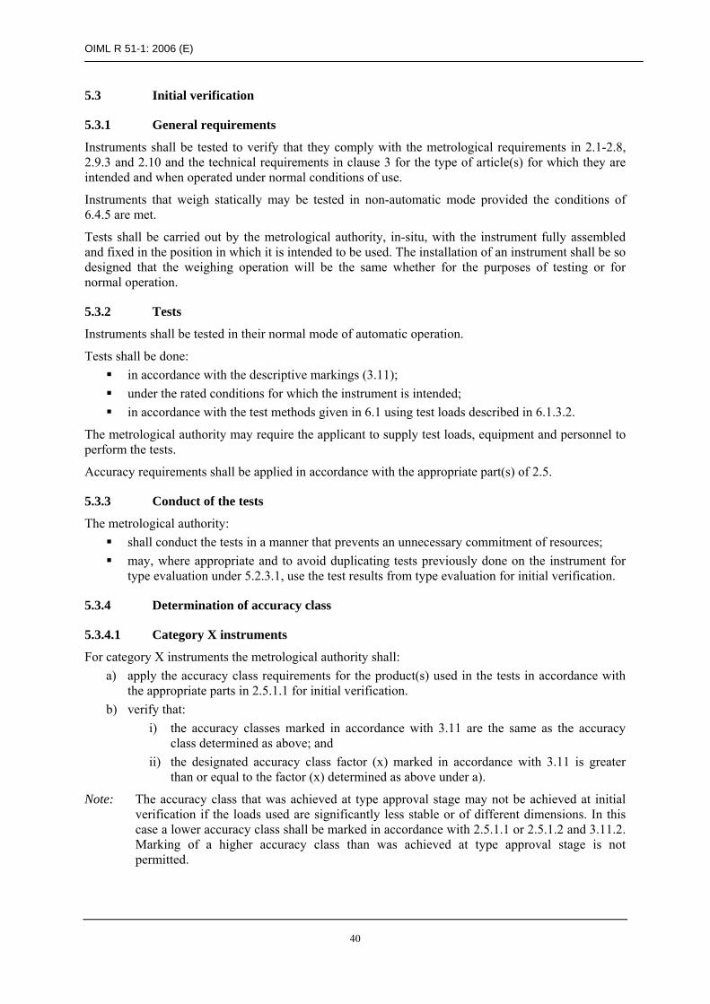
OIML R 51-1: 2006 (E)
40
5.3 Initial verification
5.3.1 General requirements
Instruments shall be tested to verify that they comply with the metrological requirements in 2.1-2.8, 2.9.3 and 2.10 and the technical requirements in clause 3 for the type of article(s) for which they are intended and when operated under normal conditions of use.
Instruments that weigh statically may be tested in non-automatic mode provided the conditions of 6.4.5 are met.
Tests shall be carried out by the metrological authority, in-situ, with the instrument fully assembled and fixed in the position in which it is intended to be used. The installation of an instrument shall be so designed that the weighing operation will be the same whether for the purposes of testing or for normal operation.
5.3.2 Tests
Instruments shall be tested in their normal mode of automatic operation.
Tests shall be done: in accordance with the descriptive markings (3.11); under the rated conditions for which the instrument is intended; in accordance with the test methods given in 6.1 using test loads described in 6.1.3.2.
The metrological authority may require the applicant to supply test loads, equipment and personnel to perform the tests.
Accuracy requirements shall be applied in accordance with the appropriate part(s) of 2.5.
5.3.3 Conduct of the tests
The metrological authority: shall conduct the tests in a manner that prevents an unnecessary commitment of resources; may, where appropriate and to avoid duplicating tests previously done on the instrument for
type evaluation under 5.2.3.1, use the test results from type evaluation for initial verification.
5.3.4 Determination of accuracy class
5.3.4.1 Category X instruments
For category X instruments the metrological authority shall: a) apply the accuracy class requirements for the product(s) used in the tests in accordance with
the appropriate parts in 2.5.1.1 for initial verification. b) verify that:
i) the accuracy classes marked in accordance with 3.11 are the same as the accuracy class determined as above; and
ii) the designated accuracy class factor (x) marked in accordance with 3.11 is greater than or equal to the factor (x) determined as above under a).
Note: The accuracy class that was achieved at type approval stage may not be achieved at initial verification if the loads used are significantly less stable or of different dimensions. In this case a lower accuracy class shall be marked in accordance with 2.5.1.1 or 2.5.1.2 and 3.11.2. Marking of a higher accuracy class than was achieved at type approval stage is not permitted.

OIML R 51-1: 2006 (E)
41
5.3.4.2 Category Y instruments
For category Y instruments the metrological authority shall apply the requirements for the accuracy class marked in accordance with the appropriate parts specified in 2.5.1.2.
5.4 Subsequent metrological control
5.4.1 Subsequent verification
Subsequent verification shall be carried out in accordance with the same provisions as in 5.3 for initial verification.
5.4.2 In-service inspection
In-service inspection shall be carried out in accordance with the same provisions as in 5.3 for initial verification, with the exception that the in-service maximum permissible errors shall be applied.
6 TEST METHODS
6.1 Automatic operation
6.1.1 Values of the mass of test loads
Test loads shall be applied as follows: test load values close to Min and Max; test load values close to, but not above, two critical points (T.3.2.6) in between Min and Max.
Note: To achieve the maximum rate of operation specified for the instrument it may be necessary to use more than one test load at each of the four nominal values above.
6.1.2 Number of test weighings
The minimum number of consecutive test weighings taken and used to determine the mean error and the standard deviation of the error for category X instruments, or the individual errors for category Y instruments, shall be as specified in Table 7.
Table 7
Category Load Number of test weighings
m ≤ 1 kg 60
1 kg < m ≤ 10 kg 30
10 kg < m ≤ 20 kg 20 X
20 kg < m 10
Y Minimum of 10 for any load Note: For category Y instruments the number of test weighings shall be at least ten unless a special
test procedure is specified in the type approval certificate.

OIML R 51-1: 2006 (E)
42
6.1.3 Types of test load
6.1.3.1 Type approval
Test loads shall be used which comply with the following conditions: appropriate dimensions; constant mass; solid, non-hygroscopic, non-electrostatic, non-magnetic material; metal-to-metal contact shall be avoided.
6.1.3.2 Initial verification, subsequent verification and in-service inspection
Test loads shall be the type of article(s) which are intended to be used.
6.1.4 Conditions of tests
The load transport system shall be set to its maximum speed, and if adjustable by the operator, also at a speed approximately midway through the operating range. If the speed is related to a particular product, the speed shall be set to the preset speed for that product.
Zero shall be set at the start of each test sequence at a given load value.
6.1.5 Control instrument
A control instrument (meeting the requirements in 6.1.5.1) for determining the conventional true value of the mass of each test load shall be available for testing. The control instrument may either be separate (an instrument other than the instrument being verified) or integral.
6.1.5.1 Accuracy of control instruments
The control instrument, whether separate or integral, shall ensure the determination of the conventional true value of the mass of each test load to an accuracy of at least one-third of whichever is the smaller of the appropriate maximum permissible errors for automatic weighing in Tables 3 and 4, for category X instruments, and one-third of the appropriate maximum permissible errors in Table 5 for category Y instruments.
6.1.6 Conventional true value of the mass of the test load
The conventional true value of the mass of each test load shall be determined using either the separate or the integral control instrument described in 6.1.5.1 as appropriate.
6.1.7 Individual errors of weighings
6.1.7.1 Category X
The individual errors of weighings shall be the difference between the conventional true value of the mass of the test load as described in 6.1.6 and the indicated or printed weight value observed and recorded (see 6.1.8).
6.1.7.2 Category Y
The individual errors of weighings shall be the difference between the conventional true value of the mass of the test load as described in 6.1.6 and the indicated or printed weight value observed and recorded.

OIML R 51-1: 2006 (E)
43
To eliminate the effect of rounding error during testing, one of the following shall be used: the scale interval, d, shall be ≤ 0.2 e (see A.3.9.2.1); the mass of the test load shall be selected using the procedure in A.3.9.2.2.
Note: Where the procedure in A.3.9.2.2 is used it will not be possible to record the individual errors. It will suffice, however, to note whether or not the instrument is within the maximum permissible errors in Table 5.
6.1.8 Indicated weight for category X instruments
For category X instruments, indications and/or printouts of the weight values (or the difference between the weight value and a nominal set-point) shall be provided for each load for determining the mean error and the standard deviation of the error for each test. For this purpose the scale interval, d, shall not be greater than the appropriate limit for Table 4 multiplied by the class designation factor (x).
Alternatively, other practical means for demonstrating compliance with Tables 3 and 4 shall be provided by agreement with the metrological authority. For example, where suitable facilities for directly performing these calculations exist within the instrument under test, these may be used provided that they are checked for accuracy before use. In this situation it is not mandatory that the individual weight values are recorded. No specific method of verifying that the instrument meets the calculation requirements is given, since the method used will depend on the particular design being tested. However, any methods used shall demonstrate that the correct errors are being calculated as specified in 6.1.7.1, the correct formulae as specified in T.4.3.5 and T.4.3.6 are being used for the calculations in the instrument, and shall include at least some checks with loads. Details of the method used shall be recorded in the appropriate place in the type evaluation report.
6.2 Non-automatic (static) operation
6.2.1 Verification standards
The error of the standard test weights or masses used shall not be greater than one-third of the maximum permissible error for the load as specified in Table 6.
6.2.2 Values of the mass of the test load
Test loads shall be applied as specified for each individual test in Annex A.
6.2.3 Number of weighings
The number of test weighings at each test load may be one.
6.2.4 Test weights indication
For non-automatic (static) operation the instrument shall be provided with: a static ‘live’ weight indication; or a continually updated weight indication by simulation of the weighing cycle.
For determining the individual errors, the scale interval, d, shall be ≤ 0.2 e or, alternatively, the procedure described in A.3.10.2 shall be used.
6.3 Status of automatic correction facilities
The status of dynamic adjustment and automatic zeroing facilities shall be as specified for each individual test in Annex A.

OIML R 51-1: 2006 (E)
44
6.4 Mode of operation for testing
6.4.1 Span stability testing (6.5.3)
For span stability testing the instrument shall be tested in non-automatic (static) operation. A single static test load near maximum capacity shall be used.
6.4.2 Disturbance testing
For disturbance testing the instrument shall be tested in non-automatic (static) operation. Each test shall be performed with one small static test load.
6.4.3 Warm-up test (A.5.2)
The warm-up test shall be performed in non-automatic (static) operation. A single static test load near maximum capacity shall be used.
6.4.4 Eccentricity (A.5.6)
For instruments that weigh dynamically in automatic operation, the effect of eccentric loading shall be determined in automatic operation using a test load of 1/3 Max (plus the additive tare capacity, if applicable) using the portion of the load transport system that is halfway between the center and the back, and repeated with the same test load using the portion of the load transport system that is halfway between the center and the front.
For instruments that weigh statically in automatic operation, the effect of eccentric loading shall be determined in non-automatic (static) operation with a test load of 1/3 Max (plus the additive tare capacity, if applicable) located in the center (A.5.7.2) and in each of the four quarter segments of the stationary load transport system.
On an instrument with a load transport system having n points of support, with n > 4, the fraction 1/(n – 1) of Max (plus the additive tare capacity, if applicable) shall be applied to each point of support.
6.4.5 Influence factor tests
The mode of operation required for influence factor tests shall be decided as follows.
All instruments designed to weigh loose material may be tested in non-automatic (static) operation.
All tests with loads greater than or equal to 20 kg may be done in non-automatic (static) operation.
For instruments that weigh pre-assembled discrete loads dynamically, the mode of operation for influence factor tests shall be as specified for each individual test in Annex A.
For instruments that weigh pre-assembled discrete loads statically, the mode of operation for influence factor tests may be as specified for each individual test in Annex A or may be decided on by the procedure of 6.4.5.1.
6.4.5.1 Option for non-automatic (static) testing
As an alternative to automatic operation during influence factor testing, static test loads may be applied in a non-automatic (static) operation provided that:
the instrument weighs statically in normal operation; the test of 6.4.5.2 has demonstrated that random errors are not significant in normal operation;
and where a decision is made to test in non-automatic (static) operation this shall be applied to all
the influence factor tests and recorded in the test report.

OIML R 51-1: 2006 (E)
45
6.4.5.2 Determination of random errors for instruments that weigh statically
To determine whether static loads may be used for influence factor testing, the following test shall be applied before approval testing takes place: automatic test weighings, as specified in 6.1, shall be applied to the instrument under normal conditions of use for Min and Max load values and for the load transport system set to its maximum speed of operation and also approximately midway through the operating speed range.
Static loads may be used for influence factor testing where the results of these tests demonstrate that, for the test loads, the differences between the results of several weighings of the same load are not greater than the absolute value of the maximum permissible error of the instrument for that load given in Table 6 for initial verification.
6.5 Examination and tests of electronic instruments
The examination and testing of an electronic weighing instrument is intended to verify compliance with the applicable requirements of this Recommendation and especially with the requirements of clause 4.
6.5.1 Examination
An electronic weighing instrument shall be examined to obtain a general appraisal of its design and construction.
6.5.2 Performance test
An electronic weighing instrument or electronic device, as appropriate, shall be tested as specified in Annex A to determine the correct functioning of the instrument.
Tests are to be carried out on the whole instrument except when the size and/or configuration of the instrument does not lend itself to testing as a unit. In such cases the electronic devices shall be tested, where possible as a simulated instrument including all electronic elements of a system which can affect the weighing result. In addition, an examination shall be carried out on the fully operational weighing instrument.
Susceptibility that would result from the use of electronic interfaces to other equipment shall be simulated in the tests.
6.5.3 Span stability test
The span stability test shall be conducted as described in A.7, applying the requirements given in 2.10.

OIML R 51-1: 2006 (E)
46
ANNEX A (Mandatory)
Testing procedures for automatic catchweighing instruments
A.1 Examination for type approval
A.1.1 Documentation (5.2.1)
Review the documentation that is submitted, including necessary photographs, drawings, diagrams, general software information, relevant technical and functional description of main components, devices, etc. to determine if it is adequate and correct. Consider the operational manual.
A.1.2 Compare construction with documentation
Examine the various devices of the instrument to ensure compliance with the documentation.
A.1.3 Metrological characteristics
Note the metrological characteristics according to the checklist given in the Test Report Format, OIML R 51-2.
A.1.4 Technical requirements (3)
Examine the instrument for conformity with the technical requirements according to the checklist in the Test Report Format, OIML R 51-2.
A.1.5 Functional requirements (4.2)
Examine the instrument for conformity with the functional requirements according to the checklist given in the Test Report Format, OIML R 51-2.
A.2 Examination for initial verification
A.2.1 Compare construction with documentation
Examine the instrument for conformity with the approved type.
A.2.2 Descriptive markings (3.11)
Check the descriptive markings according to the check-list given in the Test Report Format, OIML R 51-2.
A.3 General test conditions
A.3.1 Voltage supply
Power-up the equipment under test (EUT) for a time period equal to or greater than the warm-up time specified by the manufacturer and maintain the EUT energized for the duration of the test.

OIML R 51-1: 2006 (E)
47
A.3.2 Zero-setting
Adjust the EUT as closely as practicable to zero prior to each test and do not readjust at any time during the test, except to reset if a significant fault has occurred.
The status of automatic zero facilities shall be as specified for each test.
A.3.3 Dynamic setting
Dynamic setting shall be done in accordance with the manufacturer’s instructions prior to commencing the tests.
Before commencing influence factor tests, dynamic setting may be repeated for each load value and thereafter may not be repeated.
Dynamic setting should not be repeated during disturbance tests except after a significant fault.
If the dynamic setting process is part of a calibration procedure for the whole weighing range then the dynamic setting should not be repeated before testing with different load values.
A.3.4 Static test loads
Static test loads shall be used for the influence factor testing in A.6.2 for machines designed to weigh loose material. For machines that weigh statically, where the conditions in 6.4.5 are met (including a test applied before the testing in A.6.2 commences) static test loads may optionally be used.
A.3.5 Temperature
Except for the temperature test (A.6.2.1) and the humidity test (A.6.2.3), the tests shall be performed at a steady ambient temperature, usually normal room temperature unless otherwise specified. The temperature is deemed to be steady when the difference between the extreme temperatures noted during the test does not exceed one-fifth of the temperature range of the instrument without being greater than 5 °C, and the rate of change does not exceed 5 °C per hour.
The handling of the instrument shall be such that no condensation of water occurs on the instrument.
A.3.6 Recovery
After each test, allow the instrument to recover sufficiently before the following test.
A.3.7 Preloading
Before each weighing test, the instrument shall be pre-loaded to Max, except for the tests in A.5.2 (warm-up) and A.6.2.2 (temperature effect on no-load).
A.3.8 Multiple range instrument
In principle, each range should be tested as a separate instrument.
A.3.9 Evaluation of error in automatic operation
A.3.9.1 Category X
For category X instruments, indications and/or printouts of the weight values (or the difference between the weight value and a nominal set-point) shall be provided for each load for determining the mean error and the standard deviation of the error. With the scale interval, d, the MPME and MPSD shall be calculated for the number of individual loads defined in 6.1.2.
Alternatively, other practical means for demonstrating compliance with Tables 3 and 4 shall be provided by agreement with the metrological authority as described in 6.1.8.

OIML R 51-1: 2006 (E)
48
A.3.9.2 Category Y
A.3.9.2.1 Indication with a scale interval not greater than 0.2 e
If an instrument with digital indication has a device for displaying the indication with an actual scale interval, d ≤ 0.2 e, this device shall be used to determine the error. When the device is used it should be noted in the Test Report.
A.3.9.2.2 Indication with a scale interval greater than 0.2 e
The rounding error included in any digital indication shall be eliminated if the actual scale interval, d, is greater than 0.2 e. This shall be accomplished by one of the following methods:
a) If possible, the mass of the test load shall be selected to eliminate the rounding error: if the maximum permissible error = 1.5 e (or 0.5 e, 2.5 e, etc.) the value of the mass of
the test load shall be selected as close as possible to a whole scale interval; if the maximum permissible error = 1.0 e (or 2.0 e, 3.0 e, etc.) the mass of the test load
shall be selected as close as possible to a whole scale interval plus (or minus) 0.5 e. or:
b) If a) is not applicable, the rounding error shall be taken into consideration by adding an additional 0.5 e to the maximum permissible errors specified in Table 5.
A.3.10 Evaluation of error in non-automatic (static) operation
A.3.10.1 Indication with a scale interval not greater than 0.2 e
If an instrument with digital indication has a device for displaying the indication with d ≤ 0.2 e, this device may be used to determine the error. If a device is used it should be noted in the Test Report.
A.3.10.2 Use of standard weights to assess rounding error
A.3.10.2.1 General method to assess error prior to rounding
For instruments with digital indication having scale interval, e, changeover points may be used to interpolate between scale intervals, i.e. to determine the indication of the instrument, prior to rounding, as follows.
At a certain load, L, the indicated value, I, is noted. Additional weights of say 0.1 e are successively added until the indication of the instrument is increased unambiguously by one scale interval (I + e). The additional load, ∆L, added to the load receptor gives the indication, P, prior to rounding by using the following formula:
P = I + 0.5 e – ∆L
The error prior to rounding is:
E = P – L = I + 0.5 e – ∆L – L
Example: An instrument with a scale interval, e, of 5 g is loaded with 1 kg and thereby indicates 1 000 g. After adding successive weights of 0.5 g, the indication changes from 1 000 g to 1 005 g at an additional load of 1.5 g. Inserted in the above formula these observations give:
P = (1 000 + 2.5 – 1.5) g = 1 001 g
Thus, the true indication prior to rounding is 1 001 g, and the error is:
E = (1 001 – 1 000) g = +1 g

OIML R 51-1: 2006 (E)
49
A.3.10.2.2 Correction for error at zero
Evaluate the error at zero load, E0, and the error at load L, E, by the method of A.3.10.2.1.
The corrected error prior to rounding, Ec, is:
Ec = E – E0
Example: If, for the example in A.3.10.2.1, the error calculated at zero load was:
E0 = +0.5 g,
the corrected error is:
Ec = +1 – (+ 0.5) = +0.5 g
A.4 Test program
A.4.1 Type evaluation (5.2.3)
Clauses A.1 and A.5 to A.7 shall normally be applied for type evaluation, using the test methods detailed in clause 6.
A.4.2 Initial verification (5.3)
For initial verification, clauses A.2 and A.5, except for A.5.2 (warm-up) and A.5.4.2 (range of zero-setting) shall be applied. For instruments mounted on vehicles, A.6.2.8 shall also be applied.
The types of test loads used shall comply with 6.1.3.2.
A.5 Metrological performance tests
A.5.1 General
A.5.1.1 Standard operational test for automatic operation (5.2.3.1)
The test procedure shall be as follows: 1) Start the automatic weighing system, including (if the EUT is installed in the place of use) the
surrounding equipment which is normally operational when the instrument is in use. 2) Set the load transport system to its maximum speed of operation (6.1.4). 3) Except where stated, select four test loads which must include values close to Min and Max
and at values close to, but not above, two critical points (T.3.2.6) in between Min and Max (6.1.1). More than one test load may be required for each of the above load values to achieve the maximum rate of operation. Weigh the test loads on the control instrument specified in 6.1.5.1 to determine the conventional true value of each test load as specified in 6.1.6.
4) The number of test weighings for each load depends on the mass of the test load as specified in 6.1.2.
5) Enable the test loads to be automatically weighed for the specified number of times and record each indication. Determine the individual errors of weighing in accordance with:
6.1.7.1 for category X instruments; 6.1.7.2 for category Y instruments.
6) Determine the mean error (T.4.3.5) and the standard deviation of the error (T.4.3.6) for category X instruments in accordance with 6.1.8, or the individual errors for category Y instruments.

OIML R 51-1: 2006 (E)
50
The standard operational test is used for a number of different tests: dynamic setting; eccentricity for dynamic weighing instruments; static temperatures; temperature effect on no load indication; voltage variation; operational tests.
A.5.1.2 Weighing performance test for non-automatic (static) operation
The following weighing test shall be performed in non-automatic (static) operation as an alternative to automatic operation during influence factor testing (A.6.2), provided the conditions of 6.4.5 are met.
Apply test loads from zero up to and including Max, and similarly remove the test loads back to zero. When determining the initial intrinsic error, at least ten different test loads shall be selected, and for other weighing tests at least five shall be selected. The test loads selected shall include Max and Min, and at values close to, but not above, those at which the maximum permissible error changes.
It should be noted that when loading or unloading weights, the load shall be progressively increased or decreased.
If the instrument is provided with an automatic zero-setting or zero-tracking device, it may be in operation during the tests, except for the temperature test. The error at zero point is then determined according to A.3.10.2.1.
A.5.1.3 Supplementary weighing test
For instruments with an initial zero-setting device with a range greater than 20 % of Max, a supplementary weighing test shall be performed using the upper limit of the range as zero point.
A.5.2 Warm-up (4.2.3)
This test is to verify that metrological performance is maintained in the period immediately after switching on. The method is to check that automatic operation is inhibited until a stable indication is obtained and to verify that zero and span errors (4.3.3) comply with the requirements during the first 30 minutes of operation. Zero-tracking and automatic zero-setting shall be disabled, unless the zero-setting operates as part of every automatic weighing cycle. In this case this function shall be enabled or simulated as part of the test.
Other test methods which verify that metrological performance is maintained during the first 30 minutes of operation may be used.
1) Disconnect the instrument from the supply for a period of at least eight hours prior to the test. 2) Reconnect the instrument and switch on while observing the indication. 3) Check that it is not possible to initiate automatic weighing until the indicator has stabilized
(4.2.4). 4) As soon as the indication has stabilized, set the instrument to zero if this is not done
automatically. 5) Determine the error at zero by the method of A.3.10.2.1, and specify this error as E0I (error of
initial zero-setting) at first and as E0 (zero-setting error) when repeating this step. 6) Apply a static load close to Max. Determine the error by the method of A.3.10.2.1 and
A.3.10.2.2.

OIML R 51-1: 2006 (E)
51
7) Verify that: the zero indication error, E0I, is not greater than 0.25 e (3.5.2); the span error is not greater than the maximum permissible error specified in Table 6
for initial verification. 8) Repeat steps 5) and 6) after 5, 15 and 30 minutes. 9) After each time interval verify that:
the zero variation error, E0 – E0I, is not greater than 0.25 e × pi; the span error is not greater than the maximum permissible error specified in Table 6
for initial verification.
A.5.3 Range of dynamic setting (3.2.3)
A.5.3.1 Range
If the dynamic setting facility is specified for a limited weighing range (or ranges) then the standard weighing test shall be done at load values close to the limits of the range for at least one of the nominal load values specified in A.5.1.1.
A.5.3.2 Out of range interlock
If the dynamic setting facility is specified for a limited weighing range (or ranges) then it shall be verified that operation and print out outside of the specified range is inhibited, by attempting to weigh loads that are close to but outside the range.
A.5.4 Zero-setting (3.5)
A.5.4.1 Modes of zero-setting
To test the automatic zero-setting device it is necessary to allow the instrument to operate through the appropriate part of the automatic cycle and then to halt the instrument before testing.
The range and accuracy of zero-setting shall be tested by applying loads as specified below in non-automatic (static) operation to the load receptor after the instrument is halted.
A.5.4.2 Range of zero-setting
A.5.4.2.1 Initial zero-setting
a) Positive range: With the load receptor empty, set the instrument to zero. Place a test load on the load receptor and switch the instrument off and then back on. Continue this process until, after placing a load on the load receptor and switching the instrument off and on, it does not reset to zero. The maximum load that can be re-zeroed is the positive portion of the initial zero-setting range.
b) Negative range: 1) Remove any load from the load receptor and set the instrument to zero. Then, if possible,
remove any non-essential components of the load receptor. If, at this point, the instrument can be reset to zero by switching it off and back on, the mass of the non essential components is used as the negative portion of the initial zero-setting range.
2) If the instrument cannot be reset to zero with the non-essential components removed, add weights to any live part of the scale until the instrument indicates zero again.
3) Then remove weights and, after each weight is removed, switch the instrument off and back on. The maximum load that can be removed while the instrument can still be reset to zero by switching it off and on is the negative portion of the initial zero-setting range.

OIML R 51-1: 2006 (E)
52
4) Alternatively, if it is not possible to test the negative range of initial zero-setting by removing parts of the instrument, the instrument may be temporarily re-calibrated with a test load applied before proceeding to step 3) above. (The test load applied for the temporary re-calibration should be greater than the permissible negative portion of the initial zero-setting range which can be calculated from the result of the positive range test).
5) If it is not possible to test the negative portion of the initial zero-setting range by these methods, then only the positive part of the initial zero-setting range need be considered.
6) Reassemble or recalibrate the instrument for normal use after the above tests.
The initial zero-setting range is the sum of the positive and negative portions.
A.5.4.2.2 Non-automatic and semi-automatic zero-setting
This test is performed in the same manner as described in A.5.4.2.1, except that the zero-setting device is used rather than switching the instrument on and off.
A.5.4.2.3 Automatic zero-setting
Remove the non-essential parts of the load receptor or re-calibrate the instrument as described in A.5.4.2.1 and place weights on the live part of the scale until it indicates zero.
Remove weights in small amounts and after each weight is removed allow the instrument to operate through the appropriate part of the automatic cycle so as to see if the instrument is reset to zero automatically.
The maximum load that can be removed so the instrument can still be reset to zero is the zero-setting range.
A.5.4.3 Accuracy of zero-setting
The accuracy of zero-setting shall be tested in non-automatic (static) operation, by incrementing load weights by a small amount as described below.
1) Set the instrument to zero and then disable the zero-setting functions. If the instrument has a zero-tracking device the indication must be brought out of the zero-tracking range (e.g. by loading with 10 e).
2) Apply loads to the load receptor. Increment each successive load by a small amount (≤ 0.2 e) to determine the additional load at which the indication changes from zero to one scale interval above zero (or from one scale interval to the next above if a load of 10 e was added to disable zero-tracking).
3) Calculate the error at zero by the method of A.3.10.2.1.
Note: For practical reasons it may not be possible to determine the accuracy of the automatic zero-setting device using the method detailed above. However, the functionality of the device shall be checked by applying a load within the zero-setting range to a static part of the load receptor before an operational test. The effect of the automatic zero-setting device and its accuracy will thus be proven by the standard operational test in A.5.1.1.
A.5.5 Stability of zero and frequency of automatic zero-setting (3.5.4)
This test is applicable for instruments with programmable automatic zero-setting and does not need to be performed for instruments that have automatic zero-setting as part of every automatic weighing cycle.
To verify that an automatic zero-setting facility will operate sufficiently often to ensure that zero error is not greater than 0.5 e, apply the following method:

OIML R 51-1: 2006 (E)
53
a) Determine the maximum permissible time interval by selecting the smaller of the two values below:
the maximum time interval specified by the manufacturer in accordance with 3.5.4; three minutes (classes XI and Y(I) instruments) or 15 minutes (all other classes),
divided by the maximum zero-change in fractions of e determined from A.6.2.2. e.g. maximum zero-change = 0.33 e per 5 °C (class Y(a) instrument),
15 minutes / 0.33 = 45 minutes (0.75 hour). b) Allow the instrument to be reset to zero automatically. c) After an interval close to the maximum permissible zero-setting interval established in 1) but
before a further automatic zero-setting, carry out the test of A.5.4.3 (accuracy of zero-setting). d) Steps 2) and 3) shall also be carried out as soon the instrument is operable after switch-on, i.e.
immediately after the normal warm-up time.
Note: The value of 3 or 15 minutes in 1) is determined by the following calculations:
a) The maximum allowable rate of change of a steady ambient temperature is 5 °C per hour.
b) 3.5.2 gives the maximum allowable zero-setting error: Ezsmax ≤ 0.25 e 3.5.5 gives the maximum allowable zero-checking error: Ezcmax ≤ 0.5 e this gives the maximum allowable zero-variation: Ezcmax – Ezsmax = 0.25 e
For class XI and Y(I) instruments: A.6.2.2 requires the maximum allowable zero-variation: Δzmax per 1 °C ≤ e with 5 °C per hour for steady ambient temperature (a): Δzmax per 0.2 h ≤ e with maximum allowable zero-variation (b): Δzmax per 3 minutes ≤ 0.25 e
For all other instruments: A.6.2.2 requires the maximum allowable zero-variation: Δzmax per 5 °C ≤ e with 5 °C per hour for steady ambient temperature (a): Δzmax per hour ≤ e with maximum allowable zero-variation (b): Δzmax per 15 minutes ≤ 0.25 e
A.5.6 Tare (3.6)
The normal mode(s) of tare setting shall be tested. Other methods which verify the requirements of 3.6 may be used where appropriate.
For a static tare, place the tare load on the load receptor and allow the tare function to operate (refer to the manufacturer’s instructions for the exact method).
For a dynamic tare, pass the load to be tared over the load receptor to allow the tare function to operate (refer to manufacturer’s instructions).
A.5.6.1 Weighing test
A.5.6.1.1 Automatic operation
The tests shall be carried out in automatic operation. Zero-setting functions shall be in operation. Operational tests (according to A.5.1.1) shall be performed with at least two different tare values. At least two test load values shall be selected, one value close to Min and one close to the maximum possible net load.
If the instrument is equipped with an additive tare device one of the weighing tests shall be performed with a tare value close to the maximum additive tare effect.

OIML R 51-1: 2006 (E)
54
A.5.6.1.2 Non-automatic (static) operation
Weighing tests (loading and unloading according to A.5.1.2) shall be performed with at least two different tare values. At least five load steps shall be selected. The steps shall include values close to Min, the values at which the MPE changes and the value close to the maximum possible net load.
If the instrument is equipped with an additive tare device one of the weighing tests shall be performed with a tare value close to the maximum additive tare effect.
A.5.6.2 Accuracy of tare setting
The accuracy of the tare device shall be established in a manner similar to the test (accuracy of zero-setting) described in A.5.4.3 with the indication set to zero using the tare device.
A.5.6.2.1 Static tare
Allow the tare device to operate, then increment the tare load by using change point weights until the indication has definitely changed by one scale interval. Verify by the method of A.3.10.2.1 that the tare setting accuracy is better than ± 0.25 e with a deviation of not more than 0.25 e.
A.5.6.2.2 Dynamic tare
Allow the tare device to operate, halt the instrument, and determine the accuracy as described in A.5.6.2.1 above or, if this method is impractical, the accuracy of the dynamic tare setting shall be tested by the operational tests in A.5.6.1 to verify that the value of the net load is within the MPE.
A.5.7 Eccentricity (2.8.1 and 6.4.4)
A.5.7.1 Eccentric test for instruments that weigh dynamically
The instrument shall be under conditions of normal operation. The test shall be carried out during automatic operation. Zero-setting and zero-tracking functions shall be in operation. Dynamic setting may be performed before each new value of test load is used.
Apply a load equal to 1/3 Max (plus the additive tare capacity, if applicable) across the load receptor with the load at the center of each of the following bands where:
Band 1 is from the center of the load receptor to one edge of the transport system; Band 2 is from the center of the load receptor to the opposite edge of the transport system.
The load is passed across the load receptor the specified number of times (6.1.2). The errors shall not exceed the appropriate maximum permissible errors for influence factor tests.
A.5.7.2 Eccentric test for instruments that weigh statically
Apply a load equal to 1/3 Max (plus the additive tare capacity, if applicable) in each of the four quarter segments of the stationary load transport system. On an instrument with a load transport system having n points of support with n > 4, the fraction 1/(n – 1) of Max (plus the additive tare capacity, if applicable) shall be applied to each point of support.
The load shall be applied centrally in the segment if a single weight is used, but applied uniformly over the segment, if several small weights are used.
The errors shall not exceed the appropriate maximum permissible errors for influence factor tests.
A.5.8 Alternative operating speeds (6.1.4)
The test procedure shall be as follows.
Start the automatic weighing system, including the surrounding equipment which is normally used when the instrument is in use. The test shall be carried out during automatic operation. Zero-setting

OIML R 51-1: 2006 (E)
55
functions shall be in operation. Dynamic setting may be performed before each new value of test load is used.
Two test load values are selected, one value close to Min and one value close to Max. One test load is used at each of the above load values.
The number of test weighings depends on the mass of the test load (6.1.2).
The load transport system shall be set to its maximum speed of operation and also at a speed approximately midway through the operating range (6.1.4).
If the instrument is specified for alternative maximum capacities corresponding to alternative operating speeds then each speed must be tested with the correct load. In this case it is not necessary to retest minimum and critical load values for each speed.
The test load is passed across the load receptor the specified number of times and the results are noted. Maximum permissible errors shall be as specified in 2.5.1 as appropriate.
A.5.9 Test for the stability of equilibrium (3.4.1)
This test is applicable only to instruments that weigh statically.
Check that the following stable equilibrium functions are described in the manufacturer’s documentation in sufficient detail:
the basic principle and operation of, and the criteria for stable equilibrium; all adjustable and non-adjustable parameters of the stable equilibrium function (time interval,
number of measuring cycles, etc.); securing of these parameters; definition of the most critical adjustment of the stable equilibrium.
Apply a load up to 50 % of Max or up to a load included in the range of operation of the relevant function. Manually disturb the equilibrium by one single action and initiate the command for printing, data storage, or other function, as soon as possible. In the case of printing or data storage, read the indicated value five seconds after printing. Stable equilibrium is considered to be achieved when no more than two adjacent values are indicated, one of which being the printed final weight value (T.3.2.4.3). In the case of zero-setting or tare setting, check the accuracy as described in A.5.4.3 and A.5.5.2. Perform the test five times.
Check whether under continuous disturbance of the equilibrium no functions can be performed that require stable equilibrium, e.g. printing, storing, or zero operations.
A.5.10 Agreement between indicating and printing devices (2.8.2)
During the tests verify that for the same load, the difference between any two indicating devices having the same scale interval is as follows:
zero for digital indicating or printing devices; not greater than the maximum permissible error for analog devices.
A.5.11 Securing of components and preset controls (3.2.6)
Verify that it is not possible to make unauthorized adjustments or resetting of components, interfaces, software devices and preset controls without any access becoming automatically evident.

OIML R 51-1: 2006 (E)
56
A.6 Influence factor and disturbance tests
A.6.1 Test conditions
Further guidance on the metrological performance testing requirements for influence quantities and disturbances is provided in the appropriate reference standards as indicated for each test and in the OIML International Document D 11 [4].
A.6.1.1 General requirements
Influence factor and disturbance tests are intended to verify that electronic instruments can perform and function as intended in the environment and under the conditions specified. Each test indicates, where appropriate, the reference condition under which the intrinsic error is determined.
The influence factor tests shall be applied to a complete instrument under normal operation in accordance with 6.4.5. Where it is not possible to apply influence factor tests to fully operational equipment in their normal operational state (i.e. where size and/or configuration of the instrument does not permit testing as a whole) the instrument may be subjected to influence factor tests under simulated operation. If simulated operation is not possible, the instrument may be subjected to influence factor tests under static conditions as specified in 6.4.5.1.
Disturbances shall be applied to the instrument under static conditions. If the instrument cannot be subjected to disturbances under static conditions, then simulated operation may be permitted. The permissible effects of the disturbances, under these conditions, are specified for each test in A.6.3.
When the effect of one influence factor is being evaluated, all other factors shall be held relatively constant, at a value close to normal.
Where parts of the instrument are examined separately, errors shall be apportioned in accordance with 5.2.3.4.
The operational status of the instrument or simulator shall be recorded for each test.
When an instrument is connected in other than a normal configuration, the procedure shall be mutually agreed by the metrological authority and the applicant.
A.6.1.2 Simulator requirements
A.6.1.2.1 General
Where permitted, the simulator used for influence factor and disturbance tests should include all the electronic devices of the weighing system.
A.6.1.2.2 Weight simulator
The simulator should also include the load cell and a means to apply test loads. Where this is not possible, e.g. for high capacity instruments such as vehicle mounted catchweighers, then a load cell simulator may be used or alternatively the load cell interface may be modified to incorporate a scaling factor to give the design output for a small test load.
The simulator must be capable of providing a minimum input signal, μV/d (minimum input voltage per scale interval).
Repeatability and stability of a load cell simulator should make it possible to determine the performance of the instrument with at least the same accuracy as when the instrument is tested with weights.
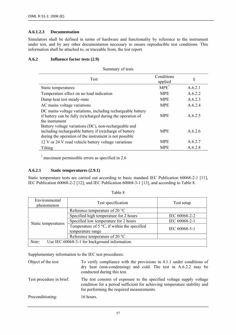
OIML R 51-1: 2006 (E)
57
A.6.1.2.3 Documentation
Simulators shall be defined in terms of hardware and functionality by reference to the instrument under test, and by any other documentation necessary to ensure reproducible test conditions. This information shall be attached to, or traceable from, the test report.
A.6.2 Influence factor tests (2.9)
Summary of tests
Test Conditions applied §
Static temperatures MPE* A.6.2.1 Temperature effect on no load indication MPE A.6.2.2 Damp heat test steady-state MPE A.6.2.3 AC mains voltage variations MPE A.6.2.4 DC mains voltage variations, including rechargeable battery if battery can be fully (re)charged during the operation of the instrument
MPE A.6.2.5
Battery voltage variations (DC), non-rechargeable and including rechargeable battery if (re)charge of battery during the operation of the instrument is not possible
MPE A.6.2.6
12 V or 24 V road vehicle battery voltage variations MPE A.6.2.7 Tilting MPE A.6.2.8
* maximum permissible errors as specified in 2.6
A.6.2.1 Static temperatures (2.9.1)
Static temperature tests are carried out according to basic standard IEC Publication 60068-2-1 [11], IEC Publication 60068-2-2 [12], and IEC Publication 60068-3-1 [13], and according to Table 8.
Table 8
Environmental phenomenon Test specification Test setup
Reference temperature of 20 °C Specified high temperature for 2 hours IEC 60068-2-2 Specified low temperature for 2 hours IEC 60068-2-1 Temperature of 5 °C, if within the specified temperature range IEC 60068-3-1
Static temperatures
Reference temperature of 20 °C Note: Use IEC 60068-3-1 for background information.
Supplementary information to the IEC test procedures:
Object of the test: To verify compliance with the provisions in 4.1.1 under conditions of dry heat (non-condensing) and cold. The test in A.6.2.2 may be conducted during this test.
Test procedure in brief: The test consists of exposure to the specified voltage supply voltage condition for a period sufficient for achieving temperature stability and for performing the required measurements.
Preconditioning: 16 hours.

OIML R 51-1: 2006 (E)
58
Condition of the EUT: EUT connected to the voltage supply source and “on” for a time period equal to or greater than the warm-up time specified by the manufacturer. Voltage supply is to be “on” for the duration of the test. The zero-setting and zero-tracking facilities shall be enabled as for normal operation.
Stabilization: 2 hours at each temperature under “free air” conditions. “Free air” conditions mean a minimum air circulation to keep the temperature at a stable level.
Temperature: As specified in 2.9.1.
Temperature sequence: a) At the reference temperature (normally 20 °C but for classes XI and Y(I) instruments the mean value of the specified temperature limits),
b) At the specified high temperature, c) At the specified low temperature, d) At a temperature of 5 °C, if it is within the specified range, and e) At the reference temperature.
Barometric pressure: For classes XI and Y(I) instruments, changes in barometric pressure shall be taken into account.
Number of test cycles: At least one cycle.
Weighing test: After stabilization at the reference temperature and again at each specified temperature, conduct weighing tests in automatic mode with the maximum rate of operation (see A.5.1.1) except where specified in 6.4.5, using test loads of mass and test weighings according to 6.1.1 and 6.1.2. (For non-automatic (static) tests see A.5.1.2). Record the following: a) date and time, b) temperature, c) relative humidity, d) test load, e) indications (as applicable), f) errors, g) functional performance.
Maximum allowable variations:
All functions shall operate as designed.
All indications shall be within the maximum permissible errors specified in 2.6.
A.6.2.2 Temperature effect on the no-load indication (2.9.1.3)
No reference to international standards can be given at the present time. This test should therefore be conducted as described below.
This test does not need to be performed for instruments that have automatic zero-setting as part of every automatic weighing cycle.
The instrument is set to zero, the temperature is then changed to the prescribed highest and lowest temperature and to 5 °C. After stabilization the error of the zero indication is determined. The change in zero indication per 1 °C (classes XI and Y(I) instruments) or per 5 °C (other instruments) is calculated. The changes of these errors per 1 °C (classes XI and Y(I) instruments) or per 5 °C (other instruments) are calculated for any two consecutive temperatures of this test.

OIML R 51-1: 2006 (E)
59
This test may be performed together with the temperature test (A.6.2.1). The errors at zero shall then be additionally determined immediately before changing to the next temperature and after the 2 hour period after the instrument has reached stability at this temperature.
Note: Pre-loading is not allowed before these measurements.
If the instrument is provided with automatic zero-setting or zero-tracking, it shall not be in operation.
Maximum allowable variations: The zero indication shall not vary by more than one verification scale interval for a temperature difference of 1 °C (classes XI and Y(I) instruments) or 5 °C (other instruments).
Condition of the EUT: EUT connected to the voltage supply source and “on” for a time period equal to or greater than the warm-up time specified by the manufacturer. Voltage supply is to be “on” for the duration of the test.
Barometric pressure: For classes XI and Y(I) instruments, changes in barometric pressure shall be taken into account.
A.6.2.3 Damp heat, steady state - non-condensing (4.1.2)
These tests are not applicable to classes XI and Y(I) instruments, or classes XII and Y(II) instruments where e is less than 1 gram.
Damp heat, steady state test are carried out according to basic standard IEC Publication 60068-2-78 [14] and IEC Publication 60068-3-4 [15] and according to Table 9.
Table 9
Environmental phenomenon Test specification Test setup
Damp heat, Steady state
Upper limit temperature and relative humidity of 85 % for 48 hours
IEC 60068-2-78 IEC 60068-3-4
Note: Use IEC 60068-3-4 for guidance for damp heat tests.
Supplementary information to the IEC test procedures:
Object of the test: To verify compliance with the provisions in 4.1.1 under conditions of high humidity and constant temperature.
Test procedure in brief: Five different test loads (A.5.1.2) in non-automatic (static) operation for instruments weighing statically or dynamically independent of the conditions of 6.4.5.
Preconditioning: None required.
Condition of the EUT: EUT connected to the voltage supply source and “on” for a time period equal to or greater than the warm-up time specified by the manufacturer. The zero-setting and zero-tracking facilities shall be enabled as for normal operation.
The handling of the EUT shall be such that no condensation of water occurs on the EUT.
Stabilization: 3 hours at reference temperature and 50 % humidity.
2 days at the upper limit temperature as specified in 2.9.1.

OIML R 51-1: 2006 (E)
60
Temperature: Reference temperature (20 °C or the mean value of the temperature range whenever 20 °C is outside this range) and at the upper limit as specified in 2.9.1.
Temperature-humidity 48 hour sequence:
a) Reference temperature at 50 % humidity, b) Upper limit temperature at 85 % humidity, c) Reference temperature at 50 % humidity.
Barometric pressure: For classes XI and Y(I) instruments, changes in barometric pressure shall be taken into account.
Number of test cycles: At least one cycle.
Weighing test: After stabilization of the EUT at reference temperature and relative humidity of 50 % apply at least five different test loads or simulated loads selected from 6.1.1 and perform the non-automatic (static) operation test in A.5.1.2. Record the following: a) date and time, b) temperature, c) relative humidity, d) supply voltage, e) test load, f) indications (as applicable), g) errors, h) functional performance.
After stabilization of the EUT at the upper limit temperature and relative humidity of 85 % perform the weighing test (A.5.1.2) and record the data as indicated above.
After stabilization of the EUT at the reference temperature and relative humidity of 50 % perform the weighing test (A.5.1.2) and record the data as indicated above.
Allow full recovery of the EUT before any other tests are performed.
Maximum allowable variations:
All functions shall operate as designed.
All indications shall be within the maximum permissible errors specified in 2.6.
A.6.2.4 AC mains voltage variations (2.9.2, 4.2.5)
AC mains voltage variations tests are carried out according to basic standard IEC Publications 61000-2-1 [16], 61000-4-1 [17] and 61000-4-11 [19], and according to Table 10.
Table 10
Environmental phenomenon Test specification Test setup
Unom
Upper limit: 110 % of Umax
Lower limit: 85 % of Umin AC mains voltage variations
Unom
IEC 61000-2-1 IEC 61000-4-1
IEC 61000-4-11
Note: In the case of three-phase mains voltage, the voltage variation shall apply for each phase successively.

OIML R 51-1: 2006 (E)
61
Supplementary information to the IEC test procedures:
Object of the test: To verify compliance with the provisions in 4.1.1 under conditions of AC mains voltage variations.
Test procedure in brief:
Preconditioning: None required.
Condition of the EUT: EUT connected to the voltage supply source and “on” for a time period equal to or greater than the warm-up time specified by the manufacturer. Adjust the EUT as close to zero indication as practicable, prior to the test and do not readjust at any time during the test.
Number of test cycles: At least one cycle.
Weighing test: The EUT shall be tested with one test load selected from 6.1.1 at a critical value. The test shall be carried out in automatic operation (A.5.1.1), or optionally in non-automatic (static) operation (A.5.1.2) where specified in 6.4.5, in which case a test load at or near Min and a test load between 1/2 Max and Max shall be selected.
Changes in barometric pressure shall be taken into account.
Stabilize the EUT at the nominal voltage and record the following data at no load and with one load or simulated load: a) date and time, b) temperature, c) relative humidity, d) supply voltage, e) test load, f) indications (as applicable), g) errors, h) functional performance.
Repeat the test for each of the voltages defined in IEC 61000-4-1 in section 5 (noting the need in certain cases to repeat the test weighing at both ends of the voltage range) and record the indications.
Maximum allowable variations:
All functions shall operate as designed.
All indications shall be within the maximum permissible errors specified in 2.6.
A.6.2.5 DC mains voltage variations (2.9.2, 4.2.5, 4.2.6)
Instruments operating from the DC mains voltage, including rechargeable battery if full (re)charge of battery during the operation of the instrument is possible shall fulfill the tests in A.6.2, with the exception of A.6.2.4 which is to be replaced by the test according to basic standard IEC Publication 60654-2 [18] and according to Table 11.

OIML R 51-1: 2006 (E)
62
Table 11
Environmental phenomenon Test specification Test setup
Unom
Upper limit: 120 % Umax
Lower limit: Minimum operating voltage (see 2.9.2)
DC mains voltage variations
Unom
IEC 60654-2
Note: If a voltage range is marked, use the average value as Unom
Supplementary information to the IEC test procedures:
Object of the test: To verify compliance with the provisions in 4.1.1 under conditions of voltage variations in DC mains voltage supply, including rechargeable battery if battery is fully (re)charged during the operation of the instrument.
Test procedure in brief: The test consists of exposure to the specified voltage supply condition for a period sufficient for achieving temperature stability and for performing the required measurements.
Preconditioning: None.
Condition of the EUT: EUT connected to the voltage supply and “on” for a time period equal to or greater than the warm-up time specified by the manufacturer. Adjust the EUT as close to zero indication as practicable, prior to the test.
Number of test cycles: At least one cycle.
Weighing test: The EUT shall be tested with one test load selected from 6.1.1 at a critical value. The test shall be carried out in automatic operation (A.5.1.1), or optionally in non-automatic (static) operation (A.5.1.2).
Changes in barometric pressure shall be taken into account.
Stabilize the EUT at the nominal voltage and record the following data at no load and with one load or simulated load: a) date and time, b) temperature, c) relative humidity, d) supply voltage, e) test load, f) indications (as applicable), g) errors, h) functional performance.
Repeat this test at 120 % Umax, then at the minimum operating voltage defined in 2.9.2, then again at Unom, recording the indications in a)-h) above at each voltage level.
Maximum allowable variations:
All functions shall operate as designed.
All indications shall be within the maximum permissible errors specified in 2.6.
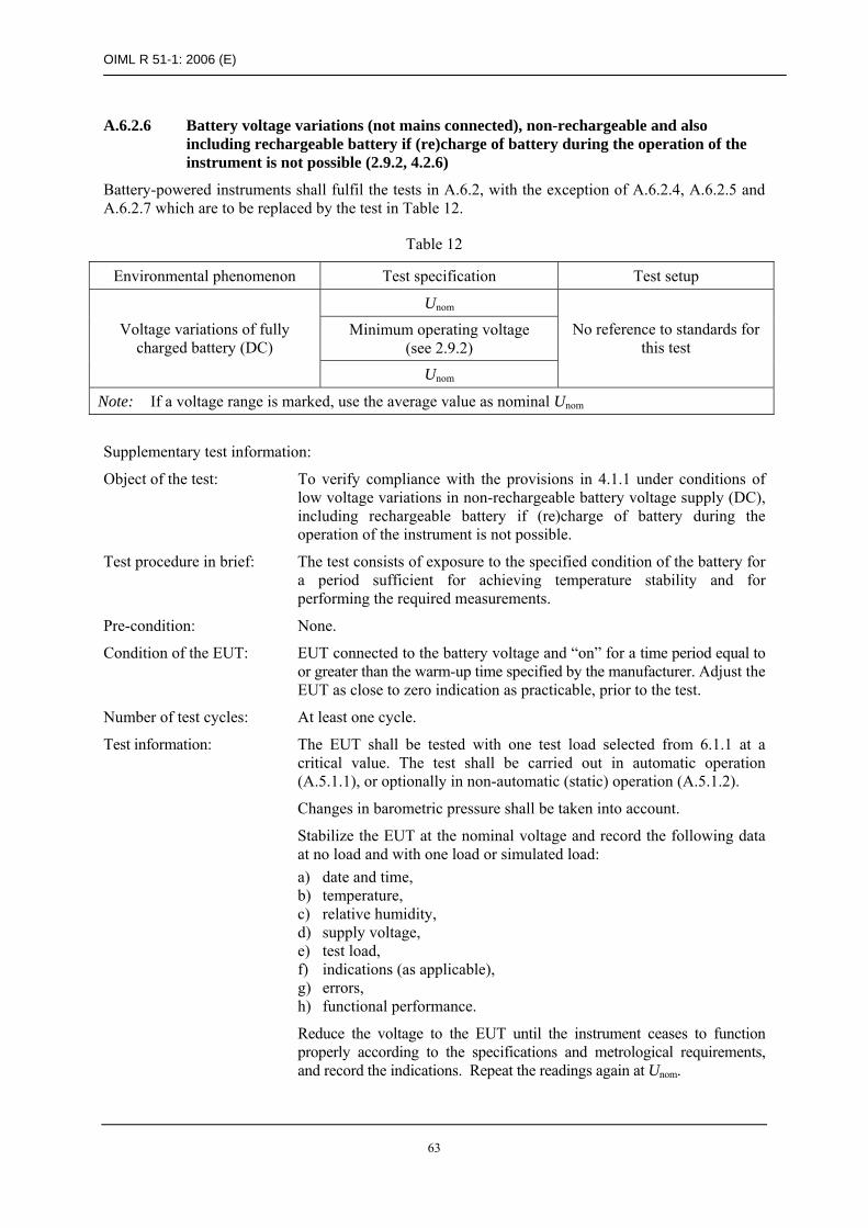
OIML R 51-1: 2006 (E)
63
A.6.2.6 Battery voltage variations (not mains connected), non-rechargeable and also including rechargeable battery if (re)charge of battery during the operation of the instrument is not possible (2.9.2, 4.2.6)
Battery-powered instruments shall fulfil the tests in A.6.2, with the exception of A.6.2.4, A.6.2.5 and A.6.2.7 which are to be replaced by the test in Table 12.
Table 12
Environmental phenomenon Test specification Test setup
Unom
Minimum operating voltage (see 2.9.2)
Voltage variations of fully charged battery (DC)
Unom
No reference to standards for this test
Note: If a voltage range is marked, use the average value as nominal Unom
Supplementary test information:
Object of the test: To verify compliance with the provisions in 4.1.1 under conditions of low voltage variations in non-rechargeable battery voltage supply (DC), including rechargeable battery if (re)charge of battery during the operation of the instrument is not possible.
Test procedure in brief: The test consists of exposure to the specified condition of the battery for a period sufficient for achieving temperature stability and for performing the required measurements.
Pre-condition: None.
Condition of the EUT: EUT connected to the battery voltage and “on” for a time period equal to or greater than the warm-up time specified by the manufacturer. Adjust the EUT as close to zero indication as practicable, prior to the test.
Number of test cycles: At least one cycle.
Test information: The EUT shall be tested with one test load selected from 6.1.1 at a critical value. The test shall be carried out in automatic operation (A.5.1.1), or optionally in non-automatic (static) operation (A.5.1.2).
Changes in barometric pressure shall be taken into account.
Stabilize the EUT at the nominal voltage and record the following data at no load and with one load or simulated load: a) date and time, b) temperature, c) relative humidity, d) supply voltage, e) test load, f) indications (as applicable), g) errors, h) functional performance.
Reduce the voltage to the EUT until the instrument ceases to function properly according to the specifications and metrological requirements, and record the indications. Repeat the readings again at Unom.

OIML R 51-1: 2006 (E)
64
Maximum allowable variations:
All functions shall operate as designed.
All indications shall be within the maximum permissible errors specified in 2.6.
A.6.2.7 12 V or 24 V road vehicle battery voltage variations (2.9.2, 4.2.6)
Instruments operated from 12 V or 24 V road vehicle battery voltage supply shall fulfill the tests in A.6.2, with the exception of A.6.2.4 and A.6.2.5 which are to be replaced by the following test according to ISO 16750-2 [25] and according to Table 13.
Table 13
Test specification Environmental phenomenon
Unom Upper limit Lower limit Test setup
12 V 16 V 9 V Voltage variations of 12 V or 24 V road vehicle batteries 24 V 32 V 16 V
ISO 16750-2
Note: The nominal voltage, Unom, of the electrical system in road vehicles is usually 12 V or 24 V. But the actual voltage at the battery terminal points can vary considerably.
Supplementary information to the ISO test procedures:
Object of the test: To verify compliance with the provisions in 4.1.1 under conditions of voltage variations of 12 V or 24 V road vehicle battery voltage supply.
Test procedure in brief: The test consists of exposure to the specified battery condition for a period sufficient for achieving temperature stability and for performing the required measurements.
Preconditioning: None.
Condition of the EUT: EUT connected to the battery voltage and “on” for a time period equal to or greater than the warm-up time specified by the manufacturer. Adjust the EUT as close to zero indication as practicable, prior to the test.
Number of test cycles: At least one cycle.
Weighing test: The EUT shall be tested with one test load selected from 6.1.1 at a critical value. The test shall be carried out in automatic operation (A.5.1.1), or optionally in non-automatic (static) operation (A.5.1.2).
Changes in barometric pressure shall be taken into account.
Stabilize the EUT at the nominal voltage and record the following data at no load and with one load or simulated load: a) date and time, b) temperature, c) relative humidity, d) supply voltage, e) test load, f) indications (as applicable), g) errors, h) functional performance.

OIML R 51-1: 2006 (E)
65
Repeat this test at the upper and lower limit voltages given in Table 13, and then again at Unom, recording the indications in a)-h) above at each voltage level.
Maximum allowable variations:
All functions shall operate as designed.
All indications shall be within the maximum permissible errors specified in 2.6.
A.6.2.8 Tilting (2.9.3)
No reference to international standards can be given at the present time. This test should therefore be conducted as described below.
Note: This test only applies to instruments that will not be permanently installed. This test is not required for transportable instruments with a leveling device and a level indicator if it can be established that the tilt can be adjusted to 1 % or less.
An instrument not intended for installation in a fixed position that does not have a leveling device and a level indicator, or an instrument mounted on or incorporated in a vehicle, shall be tested as follows:
Test information:
Object of the test: To verify compliance with the provisions in 2.9.3.
Test procedure in brief:
Preconditioning: None required.
Condition of the EUT: Voltage supply “on” for a time period equal to or greater than the warm-up time specified by the manufacturer. Voltage is to be “on” for the duration of the test. The zero-setting and zero-tracking facilities shall be enabled as for normal operation. Zero-setting and zero-tracking shall be in operation.
Number of test cycles: At least one cycle.
Test severity: Operational tests with a load close to Min and Max at 5 % tilt. For vehicle mounted or incorporated catchweighers the tests shall be performed at 10 % tilt, or at a reduced value specified by the manufacturer where the instrument is fitted with a tilt limiting device. Where applicable, a test of the operation of the tilt limiting device shall be performed.
Weighing test: The test consists of conducting the operational tests as described in 5.2.3.1 (but only using loads close to Min and Max) at each of the following positions. The test shall be carried out during automatic operation except where specified in 6.4.5. Re-zero at each new position prior to conducting the operational test: a) reference position, b) t % longitudinally forward, c) t % longitudinally backwards, d) t % transversely forward, e) t % transversely backwards, f) reference position.
Where: t % = value of tilt specified in “Test severity” above.

OIML R 51-1: 2006 (E)
66
Record: a) date and time, b) temperature, c) relative humidity, d) supply voltage, e) test load, f) indications (as applicable), g) errors, h) functional performance.
Maximum allowable variations:
All functions shall operate as designed.
All indications shall be within the maximum permissible errors specified in 2.6.
A.6.3 Disturbance tests (4.1.3)
Summary of tests
Test Condition applied §
AC mains voltage short time power reductions A.6.3.1
Electrical fast transients on mains voltage lines and on I/O circuits and communication lines sf* A.6.3.2
Electrical surges on mains voltage lines and on I/O circuits and communication lines sf A.6.3.3
Electrostatic discharge sf A.6.3.4
Electromagnetic immunity sf A.6.3.5
Electrical transient conduction for instruments powered by 12 V and 24 V batteries sf A.6.3.6
* sf: value of the significant fault (i.e. 1 e as described in T.4.3.9)
Prior to any test, the rounding error shall be set as close as possible to zero.
If there are interfaces on the instrument (or simulator), the use of these interfaces to other equipment shall be simulated in the tests. For this purpose, either an appropriate peripheral device or 3 m of interface cable to simulate the interface impedance of the other equipment, shall be connected to each different type of interface.
A.6.3.1 AC mains voltage short time power reductions
Short time power reduction (voltage dips and short interruptions) tests are carried out according to basic standard IEC Publication 61000-4-11 [19] and according to Table 14.

OIML R 51-1: 2006 (E)
67
Table 14
Test specification Test setup Environmental phenomenon Test Reduction of
amplitude to Duration /
number of cycles Test a 0 % 0.5 Test b 0 % 1 Test c 40 % 10 Test d 70 % 25 Test e 80 % 250
Voltage dips and short interruptions
Short interruption 0 % 250
IEC 61000-4-11
Note: A test generator suitable to reduce, for a defined period of time, the amplitude of one or more half cycles (at zero crossings) of the AC mains voltage shall be used. The test generator shall be adjusted before connecting the EUT. The mains voltage reductions shall be repeated 10 times with an interval between tests of at least 10 seconds.
Supplementary information to the IEC test procedures:
Object of the test: To verify compliance with the provisions in 4.1.3 under conditions of short time mains voltage interruptions and reductions while observing the weight indication of a single static load.
Test procedure in brief:
Preconditioning: None required.
Condition of the EUT: EUT connected to the voltage supply source and “on” for a time period equal to or greater than the warm-up time specified by the manufacturer. Adjust the EUT as close to zero indication as practicable, prior to the test. Zero-setting functions shall not be in operation and are not to be adjusted at any time during the test except to reset if a significant fault has occurred.
Number of test cycles: At least one cycle.
Weighing test: The EUT shall be tested with one small static test load.
Stabilize all factors at nominal reference conditions. Apply one load or simulated load and record: a) date and time, b) temperature, c) relative humidity, d) supply voltage, e) test load, f) indications (as applicable), g) errors, h) functional performance.
In accordance with the test specification in Table 14, interrupt the supply voltages to the corresponding durations / number of cycles and conduct the test as detailed in IEC 61000-4-11 section 8.2.1. During interruption observe the effect on the EUT and record as appropriate.
Maximum allowable variations:
The difference between the weight indication due to the disturbance and the indication without the disturbance either shall not exceed 1 e, or the EUT shall detect and react to a significant fault.

OIML R 51-1: 2006 (E)
68
A.6.3.2 Electrical bursts (fast transient tests) on the mains voltage lines and on the I/O circuits and communication lines
Electrical bursts tests (fast transient tests) are carried out at the positive and negative polarities for at least 1 minute at each polarity in accordance with the basic IEC Publication 61000-4-4 [20] and according to Tables 15 (ports for signal lines and control lines) and 16 (input and output AC and DC power ports).
Table 15
Environmental phenomenon Test specification Test setup
Fast transient common mode
0.5 kV (peak) 5/50 ns T1/Th 5 kHz repetition frequency
IEC 61000-4-4
Note: Applicable only to ports or interfacing with cables whose total length exceed 3 m according to the manufacturer’s functional specification.
Table 16
Environmental phenomenon Test specification Test setup standard
Fast transient common mode
1 kV (peak) 5/50 ns T1 /Th 5 kHz repetition frequency
IEC 61000-4-4
Note: DC power ports, not applicable to battery-operated appliance that cannot be connected to the mains while in use.
Supplementary information to the IEC test procedures:
Object of the test: To verify compliance with the provisions in 4.1.3 under conditions where fast transients are superimposed separately on the mains voltage, and on the I/O circuits and communication lines (if any), while observing the indications for one static test load.
Test procedure in brief: The duration of the test shall not be less than one minute for each amplitude and polarity. The injection network on the mains shall contain blocking filters to prevent the burst energy being dissipated in the mains. For the coupling of the bursts into the input/output and communication lines, a capacitive coupling clamp as defined in the reference standard shall be used.
Preconditioning: None required.
Condition of the EUT: The performance of the test generator shall be verified before connecting the EUT.
EUT connected to the voltage supply source and “on” for a time period equal to or greater than the warm-up time specified by the manufacturer. Adjust the EUT as close to zero indication as practicable, prior to the test. Zero-setting functions shall not be in operation and are not to be adjusted at any time during the test except to reset if a significant fault has occurred.
Number of test cycles: At least one cycle.
Weighing test: The EUT shall be tested with one small static test load.
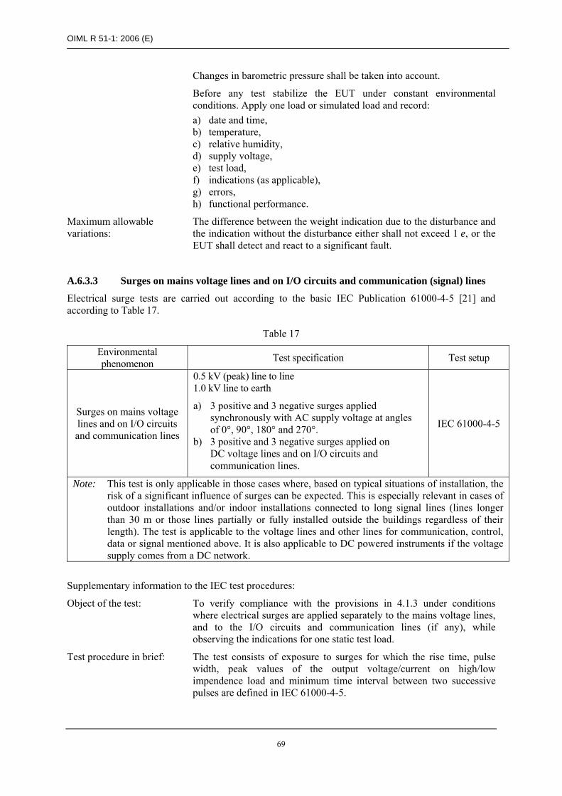
OIML R 51-1: 2006 (E)
69
Changes in barometric pressure shall be taken into account.
Before any test stabilize the EUT under constant environmental conditions. Apply one load or simulated load and record: a) date and time, b) temperature, c) relative humidity, d) supply voltage, e) test load, f) indications (as applicable), g) errors, h) functional performance.
Maximum allowable variations:
The difference between the weight indication due to the disturbance and the indication without the disturbance either shall not exceed 1 e, or the EUT shall detect and react to a significant fault.
A.6.3.3 Surges on mains voltage lines and on I/O circuits and communication (signal) lines
Electrical surge tests are carried out according to the basic IEC Publication 61000-4-5 [21] and according to Table 17.
Table 17
Environmental phenomenon Test specification Test setup
Surges on mains voltage lines and on I/O circuits and communication lines
0.5 kV (peak) line to line 1.0 kV line to earth
a) 3 positive and 3 negative surges applied synchronously with AC supply voltage at angles of 0°, 90°, 180° and 270°.
b) 3 positive and 3 negative surges applied on DC voltage lines and on I/O circuits and communication lines.
IEC 61000-4-5
Note: This test is only applicable in those cases where, based on typical situations of installation, the risk of a significant influence of surges can be expected. This is especially relevant in cases of outdoor installations and/or indoor installations connected to long signal lines (lines longer than 30 m or those lines partially or fully installed outside the buildings regardless of their length). The test is applicable to the voltage lines and other lines for communication, control, data or signal mentioned above. It is also applicable to DC powered instruments if the voltage supply comes from a DC network.
Supplementary information to the IEC test procedures:
Object of the test: To verify compliance with the provisions in 4.1.3 under conditions where electrical surges are applied separately to the mains voltage lines, and to the I/O circuits and communication lines (if any), while observing the indications for one static test load.
Test procedure in brief: The test consists of exposure to surges for which the rise time, pulse width, peak values of the output voltage/current on high/low impendence load and minimum time interval between two successive pulses are defined in IEC 61000-4-5.
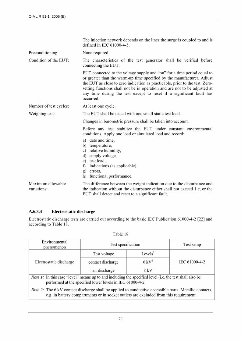
OIML R 51-1: 2006 (E)
70
The injection network depends on the lines the surge is coupled to and is defined in IEC 61000-4-5.
Preconditioning: None required.
Condition of the EUT: The characteristics of the test generator shall be verified before connecting the EUT.
EUT connected to the voltage supply and “on” for a time period equal to or greater than the warm-up time specified by the manufacturer. Adjust the EUT as close to zero indication as practicable, prior to the test. Zero-setting functions shall not be in operation and are not to be adjusted at any time during the test except to reset if a significant fault has occurred.
Number of test cycles: At least one cycle.
Weighing test: The EUT shall be tested with one small static test load.
Changes in barometric pressure shall be taken into account.
Before any test stabilize the EUT under constant environmental conditions. Apply one load or simulated load and record: a) date and time, b) temperature, c) relative humidity, d) supply voltage, e) test load, f) indications (as applicable), g) errors, h) functional performance.
Maximum allowable variations:
The difference between the weight indication due to the disturbance and the indication without the disturbance either shall not exceed 1 e, or the EUT shall detect and react to a significant fault.
A.6.3.4 Electrostatic discharge
Electrostatic discharge tests are carried out according to the basic IEC Publication 61000-4-2 [22] and according to Table 18.
Table 18
Environmental phenomenon Test specification Test setup
Test voltage Levels1
contact discharge 6 kV2 Electrostatic discharge
air discharge 8 kV
IEC 61000-4-2
Note 1: In this case “level” means up to and including the specified level (i.e. the test shall also be performed at the specified lower levels in IEC 61000-4-2.
Note 2: The 6 kV contact discharge shall be applied to conductive accessible parts. Metallic contacts, e.g. in battery compartments or in socket outlets are excluded from this requirement.

OIML R 51-1: 2006 (E)
71
Contact discharge is the preferred test method. 20 discharges (10 with positive and 10 with negative polarity) shall be applied on each accessible metal part of the enclosure. The time interval between successive discharges shall be at least 10 seconds. In the case of a non conductive enclosure, discharges shall be applied on the horizontal and vertical coupling planes as specified in IEC 61000-4-2. Air discharges shall be used where contact discharges cannot be applied. Tests with other (lower) voltages than those given in Table 18 are not required.
Supplementary information to the IEC test procedures:
Object of the test: To verify compliance with the provisions in 4.1.3 under conditions where electrostatic discharges are applied while observing the weight indication for one small static test load.
Test procedure in brief:
Preconditioning: None required.
Condition of the EUT: The performance of the test generator shall be verified before connecting the EUT.
EUT connected to the voltage supply and “on” for a time period equal to or greater than the warm-up time specified by the manufacturer. Adjust the EUT as close to zero indication as practicable, prior to the test. Zero-setting functions shall not be in operation and are not to be adjusted at any time during the test except to reset if a significant fault has occurred.
Number of test cycles: At least one cycle.
Weighing test: The EUT shall be tested with one small static test load.
Changes in barometric pressure shall be taken into account.
Before any test stabilize the EUT under constant environmental conditions. Apply one load or simulated load and record: a) date and time, b) temperature, c) relative humidity, d) supply voltage, e) test load, f) indications (as applicable), g) errors, h) functional performance.
Maximum allowable variations:
The difference between the weight indication due to the disturbance and the indication without the disturbance either shall not exceed 1 e, or the EUT shall detect and react to a significant fault.
A.6.3.5 Electromagnetic immunity
A.6.3.5.1 Radiated electromagnetic immunity tests
Radiated, radio frequency, electromagnetic field immunity tests are carried out according to the basic IEC Publication 61000-4-3 [23] and according to Table 19.
The unmodulated carrier of the test signal is adjusted to the indicated test value. To perform the test the carrier is in addition modulated as specified.
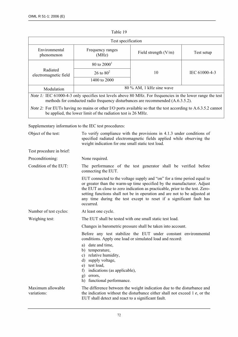
OIML R 51-1: 2006 (E)
72
Table 19
Test specification
Environmental phenomenon
Frequency ranges (MHz) Field strength (V/m) Test setup
80 to 20001
26 to 802 Radiated
electromagnetic field 1400 to 2000
10 IEC 61000-4-3
Modulation 80 % AM, 1 kHz sine wave
Note 1: IEC 61000-4-3 only specifies test levels above 80 MHz. For frequencies in the lower range the test methods for conducted radio frequency disturbances are recommended (A.6.3.5.2).
Note 2: For EUTs having no mains or other I/O ports available so that the test according to A.6.3.5.2 cannot be applied, the lower limit of the radiation test is 26 MHz.
Supplementary information to the IEC test procedures:
Object of the test: To verify compliance with the provisions in 4.1.3 under conditions of specified radiated electromagnetic fields applied while observing the weight indication for one small static test load.
Test procedure in brief:
Preconditioning: None required.
Condition of the EUT: The performance of the test generator shall be verified before connecting the EUT.
EUT connected to the voltage supply and “on” for a time period equal to or greater than the warm-up time specified by the manufacturer. Adjust the EUT as close to zero indication as practicable, prior to the test. Zero-setting functions shall not be in operation and are not to be adjusted at any time during the test except to reset if a significant fault has occurred.
Number of test cycles: At least one cycle.
Weighing test: The EUT shall be tested with one small static test load.
Changes in barometric pressure shall be taken into account.
Before any test stabilize the EUT under constant environmental conditions. Apply one load or simulated load and record: a) date and time, b) temperature, c) relative humidity, d) supply voltage, e) test load, f) indications (as applicable), g) errors, h) functional performance.
Maximum allowable variations:
The difference between the weight indication due to the disturbance and the indication without the disturbance either shall not exceed 1 e, or the EUT shall detect and react to a significant fault.

OIML R 51-1: 2006 (E)
73
A.6.3.5.2 Conducted electromagnetic immunity tests
Conducted, radio-frequency, electromagnetic field immunity tests are carried out according to the basic IEC Publication 61000-4-6 [24] and according to Table 20.
The unmodulated carrier of the test signal is adjusted to the indicated test value. To perform the test the carrier is in addition modulated as specified.
Table 20
Test specification
Environmental phenomenon
Frequency range (MHz)
RF amplitude (50 Ω) V (e.m.f) Test setup
Conducted electromagnetic field 0.15 to 80 10 V IEC 61000-4-6
Modulation 80 % AM, 1 kHz sine wave Note: This test is not applicable when the EUT has no mains or other input port.
Coupling and decoupling devices shall be used for appropriate coupling of the disturbing signal (over the entire frequency range, with a defined common-mode impedance at the EUT port) to the various conducting cables connected to the EUT.
Supplementary information to the IEC test procedures:
Object of the test: To verify compliance with the provisions in 4.1.3 under conditions of specified conducted electromagnetic fields applied while observing the weight indication for one small static test load.
Test procedure in brief:
Preconditioning: None required.
Condition of the EUT: The performance of the test generator shall be verified before connecting the EUT.
EUT connected to the voltage supply and “on” for a time period equal to or greater than the warm-up time specified by the manufacturer. Adjust the EUT as close to zero indication as practicable, prior to the test. Zero-setting functions shall not be in operation and are not to be adjusted at any time during the test except to reset if a significant fault has occurred.
Number of test cycles: At least one cycle.
Weighing test: The EUT shall be tested with one small static test load.
Changes in barometric pressure shall be taken into account.
Before any test stabilize the EUT under constant environmental conditions. Apply one load or simulated load and record: a) date and time, b) temperature, c) relative humidity, d) supply voltage, e) test load, f) indications (as applicable), g) errors, h) functional performance.

OIML R 51-1: 2006 (E)
74
Maximum allowable variations:
The difference between the weight indication due to the disturbance and the indication without the disturbance either shall not exceed 1 e, or the EUT shall detect and react to a significant fault.
A.6.3.6 Electrical transient conduction for instruments powered from a road vehicle battery
A.6.3.6.1 Conduction along supply lines of 12 V or 24 V road vehicle battery
For this test refer to ISO 7637-2 as detailed in [26] and according to Table 21.
Table 21
Environmental phenomenon Test specification Test setup
Pulse voltage, Us Test pulse Unom = 12 V Unom = 24 V
2a +50 V +50 V 2b1 +10 V +20 V 3a –150 V –200 V 3b +100 V +200 V
Conduction along 12 V or 24 V supply lines
4 –7 V –16 V
ISO 7637-2
Note 1: Test pulse 2b is only applicable if the instrument is connected to the battery via the main (ignition) switch of the car, i.e. if the manufacturer has not specified that the instrument is to be connected directly (or by its own main switch) to the battery.
Supplementary information to the ISO test procedures:
Applicable standards: ISO 7637-2 § 5.6.2: Test pulse 2a + b, § 5.6.3: Test pulse 3a + 3b, § 5.6.4: Test pulse 4.
Object of the test: To verify compliance with the provisions in 4.1.3 under the following conditions while observing the weight indication for one small static test load:
transients due to a sudden interruption of currents in a device connected in parallel with the device under test due to the inductance of the wiring harness (pulse 2a);
transients from DC motors acting as generators after the ignition is switched off (pulse 2b);
transients on the supply lines, which occur as a result of the switching processes (pulses 3a and 3b);
voltage reductions caused by energizing the starter-motor circuits of internal combustion engines (pulse 4).
Test procedures in brief:
Preconditioning: None.
Condition of the EUT: EUT connected to the voltage supply and “on” for a time period equal to or greater than the warm-up time specified by the manufacturer. Adjust the EUT as close to zero indication as practicable prior to the test. Zero-setting functions shall not be in operation and are not be adjusted at any time during the test except to reset if a significant fault has occurred.

OIML R 51-1: 2006 (E)
75
Stabilization: Before any test stabilize the EUT under constant environmental conditions.
Weighing test: The test consists of exposure of the EUT to conducted disturbances (on the voltage by direct brief coupling on supply lines) of the strength and character as specified in Table 21. Changes in barometric pressure shall be taken into account.
With the static load in place record: a) date and time, b) temperature, c) relative humidity, d) supply voltage, e) test load, f) indications (as applicable), g) errors, h) functional performance.
Repeat the test weighing for the defined voltages and record the indications.
Maximum allowable variations:
The difference between the weight indication due to the disturbance and the indication without the disturbance either shall not exceed 1 e or the instrument shall detect and react to a significant fault.
A.6.3.6.2 Electrical transient conduction via lines other than supply lines
For this test refer to ISO 7637-3 as detailed in [27] and according to Table 22.
Table 22
Environmental phenomenon Test specification Test setup
Pulse voltage, Us Test pulse Unom = 12 V Unom = 24 V
a –60 V –80 V Electrical transient conduction via lines other than supply lines
b +40 V +80 V
ISO 7637-3
Supplementary information to the ISO test procedures:
Applicable standards: ISO 7637-3, § 4.5: Test pulses a and b.
Object of the test: To verify compliance with the provisions in 4.1.3 under conditions of transients which occur on other lines as a result of the switching processes (pulses a and b).
The test shall be performed with one small test load only.
Test procedure in brief:
Preconditioning: None.
Condition of the EUT: EUT connected to the voltage supply and “on” for a time period equal to or greater than the warm-up time specified by the manufacturer. Adjust the EUT as close to zero indication as practicable prior to the test. Zero-setting functions shall not be in operation and are not to be adjusted at any time

OIML R 51-1: 2006 (E)
76
during the test except to reset if a significant fault has occurred.
Stabilization: Before any test stabilize the EUT under constant environmental conditions.
Weighing test: The test consists of exposure of the EUT to conducted disturbances (bursts of voltage spikes by capacitive and inductive coupling via lines other than supply lines) of the strength and character as specified in Table 21. Changes in barometric pressure shall be taken into account.
With the static load in place record: a) date and time, b) temperature, c) relative humidity, d) supply voltage, e) test load, f) indications (as applicable), g) errors, h) functional performance.
Repeat the test weighing for the defined voltages and record the indications.
Maximum allowable variations:
The difference between the weight indication due to the disturbance and the indication without the disturbance either shall not exceed 1 e or the instrument shall detect and react to a significant fault.
Note: An instrument must comply with the provisions in 4.1.3 in any type of vehicle.
A.7 Span stability test (6.5.3)
This test is not applicable to classes XI and Y(I) instruments.
Test method: Span stability.
Object of the test: To verify compliance with the provisions in 6.5.3 after the EUT has been subjected to the performance tests.
Reference to standard: No reference to international standards can be given at the present time.
Test procedure in brief: The test consists of observing the variations of the error of the EUT under sufficiently constant ambient conditions (reasonably constant conditions in a normal laboratory environment) at various intervals: before, during, and after the EUT has been subjected to performance tests. For instruments with an incorporated span adjustment device, the device shall be activated during this test before each measurement in order to assess its stability and its intended use.
The performance tests shall include the temperature test and, if applicable, the damp heat test. Other performance tests listed in this Annex may be performed.
The EUT shall be disconnected from the mains voltage supply, or battery supply where fitted, two times for at least 8 hours during the period of the test. The number of disconnections may be increased if so specified by the manufacturer or at the discretion of the metrological authority in the absence of any specification.
In the conduct of this test, the operating instructions for the instrument as supplied by the manufacturer shall be considered.

OIML R 51-1: 2006 (E)
77
The EUT shall be stabilized at sufficiently constant ambient conditions after switch-on for at least 5 hours, and at least 16 hours after the temperature and damp heat tests have been performed.
Test severity: Test duration: 28 days or the time period necessary to conduct the performance test, whichever is less.
Time, t, between tests: 0.5 ≤ t ≤ 10 (days). The measurements shall be evenly distributed over the total duration of the test.
Test load: a static test load near maximum capacity, Max; the same test weights shall be used throughout the test.
Maximum allowable variations:
All functions shall operate correctly.
The variation in the indication of the test load shall not exceed 1/2 the absolute value of the MPE specified in Table 6 for the test load applied on any of the n tests conducted.
Number of tests, n: n ≥ 8. If the test results indicate a trend, i.e. the errors continue to increase or decrease in the same direction, conduct additional tests until the trend comes to rest or reverses itself, or until the error exceeds the maximum allowable variation.
Preconditioning: None required.
Test equipment: Verified mass standards.
Condition of the EUT: EUT connected to the voltage supply and “on” for a time period equal to or greater than the warm-up time specified by the manufacturer.
Adjust the EUT as close to a zero indication as practicable before each test. The automatic zero-tracking should be made inoperative during the test (if the EUT is so equipped).
Test sequence: Stabilize all factors at reference conditions.
Changes in barometric pressure shall be taken into account.
Apply the test load (or simulated load) and record the following data: a) date and time, b) temperature, c) barometric pressure, d) relative humidity, e) test load, f) indication, g) errors, h) functions performance, i) changes in test location.
At the first measurement immediately repeat zeroing and loading four times to determine the average value of the error. For the next measurements perform only one, unless either the result is outside the specified tolerance or the range of the five readings of the initial measurement is more than 0.1 e. Allow full recovery of the EUT before any other tests are performed.

OIML R 51-1: 2006 (E)
78
Bibliography
Below are references to Publications of the International Electrotechnical Commission (IEC), the International Organization for Standardization (ISO) and the OIML, where mention is made in this Recommendation.
Ref. Standards and reference documents Description [1] International Vocabulary of Basic and
General Terms in Metrology (VIM) (1993) Vocabulary, prepared by a joint working group consisting of experts appointed by BIPM, IEC, IFCC, ISO, IUPAC, IUPAP and OIML.
[2] International Vocabulary of Terms in Legal Metrology, BIML, Paris (2000)
Vocabulary including only the concepts used in the field of legal metrology. These concepts concern the activities of the legal metrology service, the relevant documents as well as other problems linked with this activity. Also included in this Vocabulary are certain concepts of a general character which have been drawn from the VIM.
[3] OIML B 3 (2003)
OIML Certificate System for Measuring Instruments (formerly OIML P1)
Provides rules for issuing, registering and using OIML Certificates of conformity.
[4] OIML D 11 (2004)
General requirements for electronic measuring instruments
Contains general requirements for electronic measuring instruments.
[5] OIML R 111 (2004)
Weights of classes E1, E2, F1, F2, M1, M1–2, M2, M2–3 and M3
Provides the principal physical characteristics and metrological requirements for weights used with and for the verification of weighing instruments and weights of a lower class.
[6] OIML R 60 (2000) Metrological regulation for load cells
Provides the principal static characteristics and static evaluation procedures for load cells used in the evaluation of mass.
[7] OIML R 87 (2004)
Quantity of products in prepackages
Provides the legal metrology requirements for prepacked products labeled in predetermined constant nominal quantities of weight, volume, linear measure, area or count, and sampling plans for use by legal metrology officials in verifying the quantity of products in prepackages
[8] OIML D 19 (1988)
Pattern evaluation and pattern approval
Provides advice, procedures and influencing factors on type evaluation and type approval.
[9] OIML D 20 (1988)
Initial and subsequent verification of measuring instruments and processes
Provides advice, procedures and influencing factors on the choice between alternative approaches to verification and the procedures to be followed in the course of verification.
[10] OIML R 76-1 Non-automatic weighing instruments. 2006 Edition
Provides the principal physical characteristics and metrological requirements for the verification of non-automatic weighing instruments.
[11] IEC 60068-2-1 (1990-05) with amendments 1 (1993-02) and 2 (1994-06)
Environmental testing, Part 2: Tests, Test A: Cold
Concerns cold tests on both non heat dissipating and heat dissipating equipment under test (EUT).
[12] IEC 60068-2-2 (1974-01) with amendments 1 (1993-02) and 2 (1994-05)
Environmental testing Part 2: Tests, Test B: Dry heat
Contains test Ba: dry heat for non heat dissipating specimen with sudden change of temperature; test Bb: dry heat for non heat dissipating specimen with gradual change of temperature; tests Bc: dry heat for heat dissipating specimen with sudden change of temperature; test Bd dry heat for heat dissipating

OIML R 51-1: 2006 (E)
79
Ref. Standards and reference documents Description specimen with gradual change of temperature.
The 1987 reprint includes IEC No. 62-2-2A.
[13] IEC 60068-3-1 (1974-01) +
Supplement A (1978-01): Environmental testing Part 3 Background information, Section 1: Cold and dry heat tests
Gives background information for Tests A: Cold (IEC 68-2-1), and Tests B: Dry heat (IEC 68-2-2). Includes appendices on the effect of: chamber size on the surface temperature of a specimen when no forced air circulation is used; airflow on chamber conditions and on surface temperatures of test specimens; wire termination dimensions and material on surface temperature of a component; measurements of temperature, air velocity and emission coefficient.
Supplement A - gives additional information for cases where temperature stability is not achieved during the test.
[14] IEC 60068-2-78 (2001-08)
Environmental testing - Part 2-78: Tests - Test Cab: Damp heat, steady state (IEC 60068-2-78 replaces the following withdrawn standards: IEC 60068-2-3, test Ca and IEC 60068-2-56, test Cb)
Provides a test method for determining the suitability of electro-technical products, components or equipment for transportation, storage and use under conditions of high humidity. The test is primarily intended to permit the observation of the effect of high humidity at constant temperature without condensation on the specimen over a prescribed period.
This test provides a number of preferred severities of high temperature, high humidity and test duration. The test can be applied to both heat-dissipating and non-heat dissipating specimens. The test is applicable to small equipment or components as well as large equipment having complex interconnections with test equipment external to the chamber, requiring a setup time which prevents the use of preheating and the maintenance of specified conditions during the installation period.
[15] IEC 60068-3-4 (2001-08)
Environmental testing - Part 3-4: Supporting documentation and guidance - Damp heat tests
Provides the necessary information to assist in preparing relevant specifications, such as standards for components or equipment, in order to select appropriate tests and test severities for specific products and, in some cases, specific types of application. The object of damp heat tests is to determine the ability of products to withstand the stresses occurring in a high relative humidity environment, with or without condensation, and with special regard to variations of electrical and mechanical characteristics. Damp heat tests may also be utilized to check the resistance of a specimen to some forms of corrosion attack.
[16] IEC 61000-2-1 (1990-05)
Electromagnetic compatibility (EMC) Part 2: Environment Section 1
Electromagnetic compatibility (EMC) Part 2: Environment Section 1: Description of the environment- Electromagnetic environment for low-frequency conducted disturbances and signaling in public power supply systems.
[17] IEC 61000-4-1 (2000-04)
Basic EMC Publication Electromagnetic compatibility (EMC) Part 4: Testing and measurement techniques. Section 1: Overview of IEC 61000-4 series
Gives applicability assistance to the users and manufacturers of electrical and electronic equipment on EMC standards within the IEC 61000-4 series on testing and measurement techniques.
Provides general recommendations concerning the choice of relevant tests.

OIML R 51-1: 2006 (E)
80
[18] IEC 60654-2 (1979-01), with amendment 1
(1992-09).
Operating conditions for industrial-process measurement and control equipment - Part 2: Power
Gives the limiting values for power received by land-based and offshore industrial process measurement and control systems or parts of systems during operation.
[19] IEC 61000-4-11 (2004-03)
Electromagnetic compatibility (EMC) Part 4-11: Testing and measuring techniques - Voltage dips, short interruptions and voltage variations immunity tests
Defines the immunity test methods and range of preferred test levels for electrical and electronic equipment connected to low-voltage power supply networks for voltage dips, short interruptions, and voltage variations. This standard applies to electrical and electronic equipment having a rated input current not exceeding 16 A per phase, for connection to 50 Hz or 60 Hz AC networks. It does not apply to electrical and electronic equipment for connection to 400 Hz AC networks. Tests for these networks will be covered by future IEC standards. The object of this standard is to establish a common reference for evaluating the immunity of electrical and electronic equipment when subjected to voltage dips, short interruptions and voltage variations. It has the status of a Basic EMC Publication in accordance with IEC Guide 107.
[20] IEC 61000-4-4 (2004-07)
Electromagnetic compatibility (EMC) Part 4-4: Testing and measurement techniques - Electrical fast transient/burst immunity test
Establishes a common and reproducible reference for evaluating the immunity of electrical and electronic equipment when subjected to electrical fast transient/burst on supply, signal, control and earth ports. The test method documented in this part of IEC 61000-4 describes a consistent method to assess the immunity of an equipment or system against a defined phenomenon.
The standard defines: test voltage waveform; range of test levels; test equipment; verification procedures of test equipment; test setup; and test procedure.
The standard gives specifications for laboratory and post-installation tests.
[21] IEC 61000-4-5 (2001-04) consolidated edition 1.1 (Including Amendment 1 and Correction 1)
Electromagnetic compatibility (EMC)- Part 4-5: Testing and measurement techniques - Surge immunity test
Relates to the immunity requirements, test methods, and range of recommended test levels for equipment to unidirectional surges caused by over-voltages from switching and lightning transients. Several test levels are defined which relate to different environment and installation conditions. These requirements are developed for and are applicable to electrical and electronic equipment. Establishes a common reference for evaluating the performance of equipment when subjected to high-energy disturbances on the power and inter-connection lines.
[22] IEC 61000-4-2 (1995-01) with amendment 1 (1998-01) and amendment 2 (2000-11) Consolidated Edition: IEC 61000-4-2 (2001-04) Ed. 1.2
Basic EMC Publication.
Electromagnetic Compatibility (EMC) - Part 4: Testing and measurement techniques - Section 2: Electrostatic discharge immunity

OIML R 51-1: 2006 (E)
81
test. Basic EMC Publication. [23] IEC 61000-4-3 Consolidated Edition 2.1
(including amendment 1) (2002-09)
Electromagnetic Compatibility (EMC) - Part 4: Testing and measurement techniques - Section 3: Radiated, radio-frequency, electromagnetic field immunity test.
[24] IEC 61000-4-6 am2 (2006-05)
Electromagnetic compatibility (EMC) - Part 4-6: Testing and measurement techniques - Immunity to conducted disturbances, induced by radio-frequency fields
This part of IEC 61000-4 relates to the conducted immunity requirements of electrical and electronic equipment to electromagnetic disturbances coming from intended radio-frequency (RF) transmitters in the frequency range 9 kHz up to 80 MHz. Equipment not having at least one conducting cable (such as mains supply, signal line or earth connection) which can couple the equipment to the disturbing RF fields is excluded.
The object of this standard is to establish a common reference for evaluating the functional immunity of electrical and electronic equipment when subjected to conducted disturbances induced by radio-frequency fields. The test method documented in this part of IEC 61000 describes a consistent method to assess the immunity of an equipment or system against a defined phenomenon.
This second edition cancels and replaces the first edition published in 1996 and its amendment 1 (2000), and constitutes a technical revision.
[25] ISO 16750-2 (2003)
Road vehicles - Environmental conditions and testing for electrical and electronic equipment – Part 2: Electrical loads.
[26] ISO 7637-2 (2004)
Road vehicles - Electrical disturbance by conduction and coupling - Part 2: Electrical transient conduction along supply lines only.
[27] ISO 7637-3 (1995) with correction 1 (1995)
Road vehicles - Electrical disturbance by conduction and coupling - Part 3: Passenger cars and light commercial vehicles with nominal 12 V supply voltage and commercial vehicles with 24 V supply voltage - electrical transient transmission by capacitive and inductive coupling via lines other than supply lines.