
AUTOMATED VEHICLE FOR ENHANCED WORK …onlinepubs.trb.org/onlinepubs/shrp/SHRP-H-676.pdft SHRP-H-676...
42
t SHRP-H-676 Automated Vehicle for Enhanced Work Crew Safety Edward N. MacLeod, Principal Investigator Marianne Chiarella, Program Manager MacLeod Technologies, Inc. Strategic Highway Research Program • National Research Council Washington, DC 1994
-
Upload
duonghuong -
Category
Documents
-
view
222 -
download
2
Transcript of AUTOMATED VEHICLE FOR ENHANCED WORK …onlinepubs.trb.org/onlinepubs/shrp/SHRP-H-676.pdft SHRP-H-676...

t
SHRP-H-676
Automated Vehicle forEnhanced Work Crew Safety
Edward N. MacLeod, Principal InvestigatorMarianne Chiarella, Program Manager
MacLeod Technologies, Inc.
Strategic Highway Research Program• National Research Council
Washington, DC 1994

SHRP-H-676Contract ID033 °Product No. 4010
Program Manager: Don M. HarriottProject Manager: Shashikant C. ShahProduction Editor: Marsha Barrett
Program Area Secretary: Carina Hreib
January 1994
key words:automated follow vehicleautomated shadow vehicle
CONAC (Computerized Opto-electronic Navigation and Control)high-speed trackingintelligent navigationMOBs (Mobile Opto-electronic Beaconsobstacle detectionvehicle conversion
work zone safety
Strategic Highway Research ProgramNational Academy of Sciences2101 Constitution Avenue N.W.
Washington, DC 20418
(202) 334-3774
The publication of this report does not necessarily indicate approval or endorsement of the findings, opinions,conclusions, or recommendations either inferred or specifically expressed herein by the National Academy ofSciences, the United States Government, or the American Association of State Highway and TransportationOfficials or its member states.
© 1994 National Academy of Sciences
425/NAP/194
• TABLE OF CONTENTS
SECTION DESCRIPTION PAGE
LIST OF FIGURES ............................. ii
ACKNOWLEDGMENTS ............................ iii
EXECUTIVE SUMMARY ............................ 1
1.0 INTRODUCTION ................................. 2
2.0 PHASE I TECHNICAL OBJECTIVES ................ 12
3.0 PHASE I TASK RESULTS ........................ 15
4.0 PHASE I QUALIFICATION TESTING ............... 26
5.0 PHASE I CONCLUSIONS AND RECOMMENDATIONS ..... 34
6.0 COMMERCIAL APPLICATIONS ..................... 36
7.0 ABBREVIATIONS ............................... 37
iii

LIST OF FIGURES
FIGURE DESCRIPTION PAGE
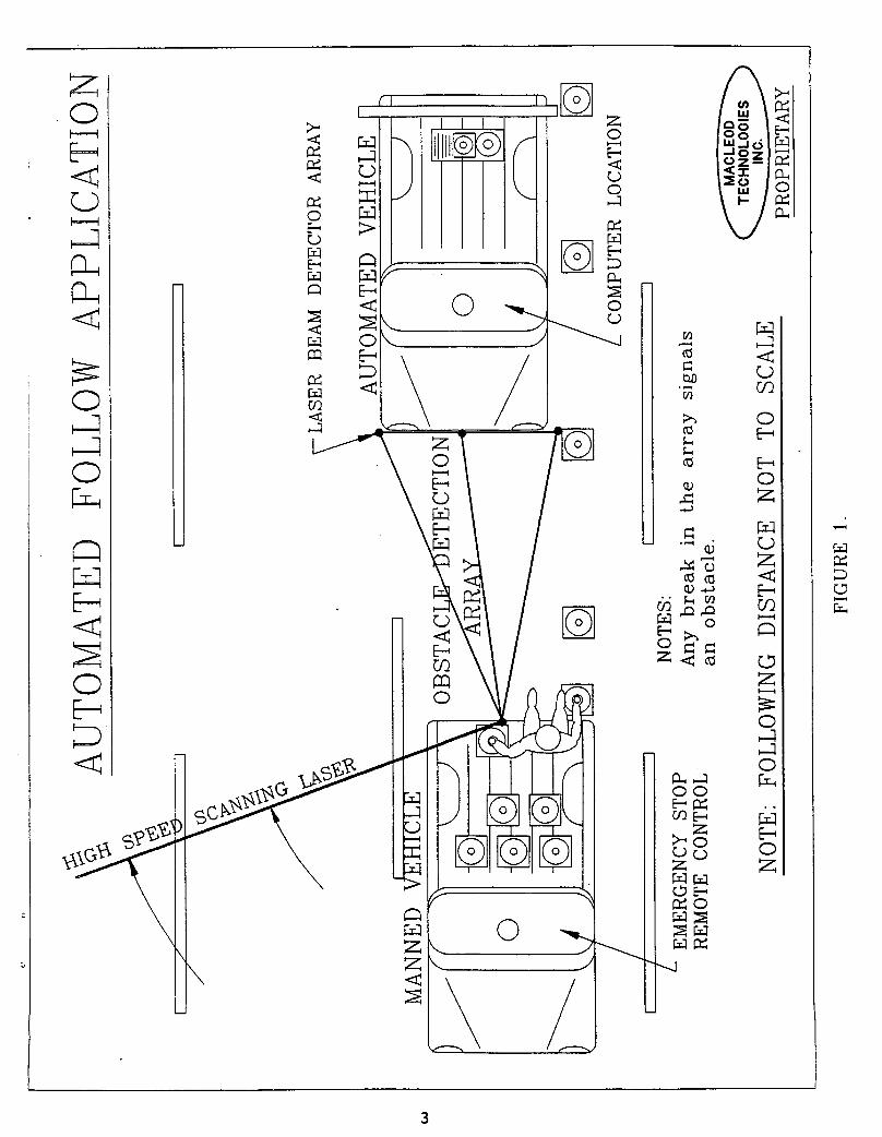
1 AUTOMATED FOLLOW APPLICATION ..................... 3
2 FULL-SCALE AUTOMATED FOLLOW VEHICLE IN
OPERATION ........................................ 4
3 CONAC - AN OVERVIEW .............................. 5
4 MOBILE OPTO-ELECTRONIC BEACON (MOB) BASICS ....... 7
5 OPTO-ELECTRONIC POSITION SENSOR (OPS)BASIC FUNCTION.. ................................. 8
6 TIME TO ANGLE CONVERSION (TOP VIEW) .............. 9
7 DISTANCE AND BEARING MEASUREMENTS ............... ii
8 SHRP PROGRAM SCHEDULE ........................... 14
9 STEERING AND FLOOR PEDAL SERVO MOTORS ........... 16
i0 SAFETY BRAKE ACTUATOR DEVICE ON FLOOR
MOUNTED SERVOS .................................. 16
11 FINAL QUALIFICATION MOB UNIT ON TOW VEHICLE ..... 17
12 AUTOMATED VEHICLE SIMULATOR ..................... 19
13 REDUCED-SCALE FOLLOW VEHICLE .................... 20
14 FOLLOW VEHICLE SOFTWARE CONTROL FLOW ............ 21
15 FOLLOW VEHICLE TURN RADIUS ...................... 22
16 OPS MOUNTED ON FULL-SCALE FOLLOW VEHICLE ........ 24
17 REMOTE OPERATOR CONTROL BOX FOR MANUAL CONTROL..24
18 FINAL PHASE I QUALIFICATION TEST SITE ........... 27
19 FULL-SCALE TOW AND FOLLOW VEHICLES .............. 27
20 VEHICLE TRACKING PERFORMANCE .................... 29
21 DISTANCE TO TOW VS TIME ......................... 30
22 ANGLE TO TOW VS TIME ............................ 32
V
!
ACKNOWLEDGMENTS
The research described herein was supported by the Strategic
Highway Research Program (SHRP). SHRP is a unit of the National
Research Council that was authorized by section 128 of the
Surface Transportation and Uniform Relocation Assistance Act of1987.
MacLeod Technologies, Inc. would like to thank Mr. S.C. Shah,
Technical Project Officer--SHRP for his assistance throughout the
project and contributions to the final report. His suggestions
and feedback were much appreciated.
We would also like to thank Mr. K.T. Thirumalai, Program Manager-
-SHRP for his support.
The assistance and cooperation with Qualification Testing of the
Mass Port Authority, Chelmsford Department of Public Works and
Hanscom Air Force Base was much appreciated.
Thanks to Jim Pearson, Superintendent of Highways, Department ofPublic Works, for the use of the Chelmsford DPW truck that was
used in the final Qualification Testing.
Thanks to John Mathieu, Operations Manager, Mass Port Authority
at Hanscom Air Force Base for the use of the runway and supportstaff.
vii

EXECUTIVE SUMMARY
The automated vehicle conversion system presented in this
report provides a low-cost method of reducing worker exposure to
hazardous conditions. Automation of a traffic control vehicle
not only eliminates the risk to the life of the driver but also
eliminates the labor expense of a driver. Safety is additionally
enhanced to work crews and motorists by allowing the system to be
used in situations where the added expense of a driver is not
practical. This is particularly true for local highway
departments with limited budgets. Future benefits include
automated collision-prevention and completely autonomous
intelligent vehicle tracking, navigation and control for IVHS.
In this Phase I, MTI has demonstrated the automated follow
vehicle capability on both reduced-scale and full-scale vehicles.
The resulting automated system is easily adaptable to existing
highway maintenance vehicles. The approach taken in Phase I has
significant potential for successful commercialization in Phase
II and beyond.

1.0 INTRODUCTION
During routine roadway maintenance it is desirable to have atraffic control vehicle follow a work crew or maintenancevehicle. Typically this vehicle would display a flashing arrowor sign to warn oncoming motorists of the work being performedahead. The driver of this vehicle is in a particularly hazardousposition from oncoming traffic, especially at night, inrestricted visibility situations, in tunnels or on bridges. MTIhas demonstrated automation of a vehicle with the goal ofreplacing the driver of the traffic control vehicle.
A typical automated follow vehicle application is illustrated inFigure i. A worker in the tow vehicle is laying down cones toblock off a work area. The automated vehicle is following behindmaintaining fixed distance and relative angle to the tow vehicle.The lead vehicle is termed the tow vehicle because it invisiblytows the follow vehicle. The navigation components depicted inFigure i, the scanning laser and laser beam detectors, are partof MTI's proprietary vehicle guidance system called CONAC. CONAC(for Computerized Opto-electronic Navigation and Control) isdescribed in detail in Sections I.I - 1.5.
The automated vehicle conversion system includes computerizedtracking/navigation control, add-on vehicle steering and pedalcontrol modules, obstacle detection and safety systems.Converted vehicles may be quickly switched between conventionalmanual driving, manual radio control or automated follow undercomputer control. The system incorporates rapid feedback fromfixed sensors positioned on the front fender of the followvehicle. Precise follow vehicle distance and angle offsetrelative to the tow vehicle are determined many times per second.
The navigation and control computer is the size of a briefcaseand resides in the automated follow vehicle. It receives
navigation data and outputs control commands to the automatedfollow car servo control motors many times per second. The add-on steering and pedal control motors replace the human driver inthe automated vehicle. Steering and pedal servo motors areadaptable to any vehicle. A typical automatic transmissionvehicle may be converted into a fully automated vehicle in lessthan one hour. Once a vehicle is converted, this vehicle may beswitched from automatic control to driver control or back in lessthan one minute.
Safety systems include ignition cut-off circuitry, a brakeactuator safety device, secure radio transmission for the remoteoperator link and obstacle detection.
The photograph provided in Figure 2 was taken during final PhaseI qualification testing at Hanscom Airport in Bedford, MA. Thisscene depicts the full-scale automated follow vehicle inoperation. The follow vehicle is a Dodge Caravan. The towvehicle is a Chelmsford, MA, DPW truck.


1.1 CONAC - AN OVERVIEW
CONAC is an acronym for Computerized Opto-electronic Navigationand Control.
COMPUTERIZED OPTO-ELECRONICNAVIGATION AND CONTROL
/""-"xCONTROL TRACKING
I CONAC 1OBSTACLE NAVIGATIONDETECTION
FIGURE 3.
AS depicted above, this new computer-based, highly intelligentmobile robot technology effectively merges obstacle detection,precision high-speed tracking, intelligent navigation, andcomputer control.
MTI is the first company to demonstrate this closed loopcapability with sufficient speed and accuracy to meet the needsof automating conventional commercial vehicles.
CONAC is the only technology specifically designed for mobilerobot tracking, navigation and control. Like Loran and GPS,CONAC uses fixed reference beacons toestablish a conventional
coordinate system. In this application CONAC navigation deviceshave been termed Mobile Opto-electronic Beacons (MOBs) and Opto-
• electronic Position Sensors (0PS). These two devices are the keycomponents in the CONAC system. The chief advantages of thissystem, over other systems, is accuracy and speed in aconventional two-dimensional Cartesian coordinate system. CONACreduces mobile robot tracking data to its absolute essence. Aseries of only four electronic pulses are able to communicatedistance and relative an_le to the control computer withextraordinary _p_d and p_clsi0n.
5

1.2 MOBILE OPTO-ELECTRONIC BEACON (MOB)
As shown in Figure 4, the MOB emits a structured laser beamcreating a fan shaped projection. Also housed in the MOB is anelectronically speed controlled motor. This precision motorspins the fan shaped of laser light around a vertical axis at anyselected rate between 1,000-i0,000 RPM, scanning the environment
many times per second. A 3000 RPM beacon was used in thisapplication.
1.3 OPTO-ELECTRONIC POSITION SENSORS (OPS)
As shown in Figure 5, an opto-electronic sensor is able toprecisely sense the passing of the scanning laser beam projectedby an MOB. The sensor produces an electrical pulse that ismeasured to one microsecond with precision digital clocks.Because the OPS electronics are extraordinarily sensitive,
minimal laser power is required. Built-in signal amplifiers andfilters produce an absolute, sharp digital pulse as the scanninglaser passes. Experiments at MTI show response delays of ourproprietary sensor is in the nanosecond range. There is no needfor the computer to interpret ambiguous signals as in otherelectronic navigation approaches.
1.4 ANGLE DETERMINATION USING TIME
The Time-to-Angle conversion illustrated in Figure 6 provides theprecise relative angle between the MOB and the selected OPS. Thereference pulse represents the pulse generated by the first OPSin a series of three. In Figure 6, the time between theReference Pulse and the OPS Pulse is T1.
The time for one complete revolution of the MOB is called ROTIME.The relative angle is then simply a ratio of times. The anglefrom the reference pulse to the OPS is defined by the followingequation:
ANGLE = 360 (degrees) x T1/ROTIME.
This angle represents the relative angle or bearing to the OPSfrom the MOB.
Using computer-compatible electronic clocks, it is possible tomeasure with great precision the relative time lapse between theReference Pulse and the OPS Pulse. The Reference Pulse triggersthe start of electronic timers on the CONAC computer. Eachsubsequent OPS pulse stops its dedicated electronic timer. Notethat the first OPS triggered is also the last OPS triggered.Each timer is accurate to better than one millionth of a second.
6

7


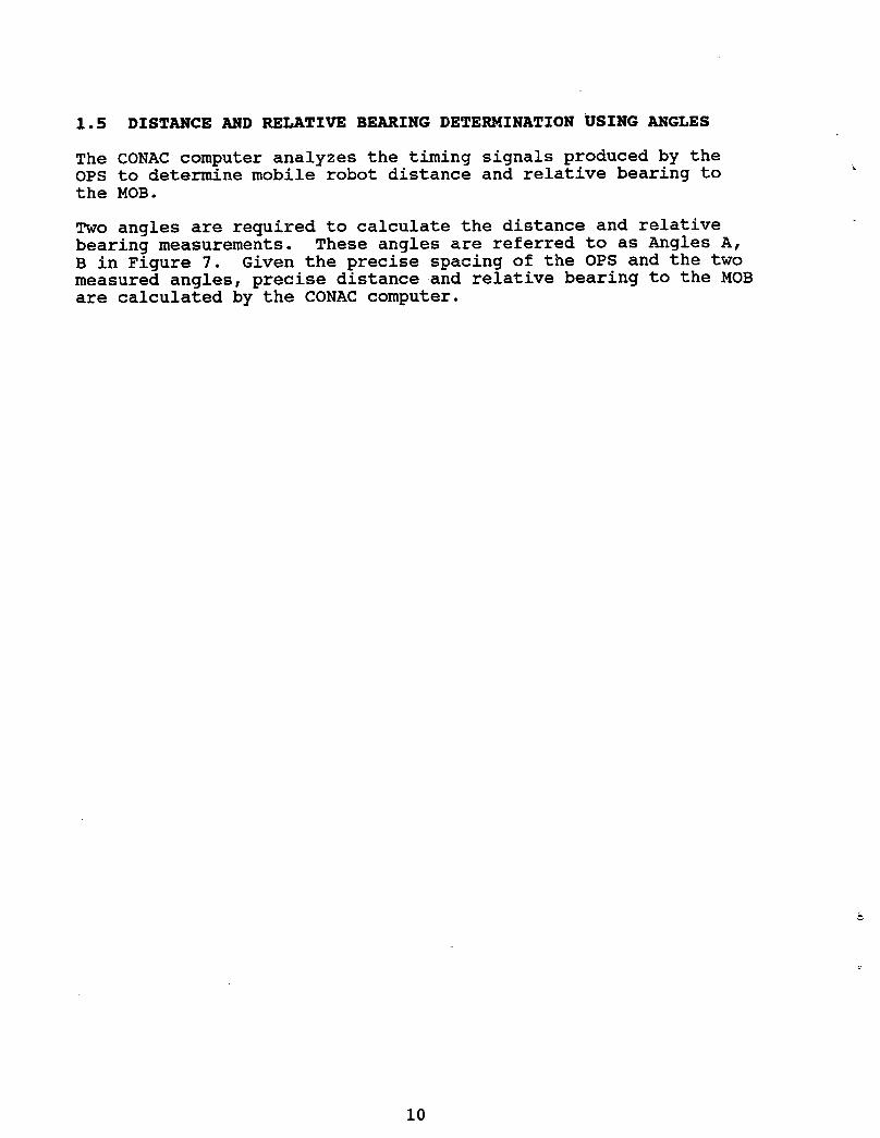
1.5 DISTANCE AND RELATIVE BEARING DETERMINATION USING ANGLES
The CONAC computer analyzes the timing signals produced by theOPS to determine mobile robot distance and relative bearing tothe MOB.
Two angles are required to calculate the distance and relativebearing measurements. These angles are referred to as Angles A,B in Figure 7. Given the precise spacing of the OPS and the twomeasured angles, precise distance and relative bearing to the MOBare calculated by the CONAC computer.
10

11

2.0 PHASE I TECHNICAL OBJECTIVES
This section outlines the key technical objectives of Phase I.The objectives listed in this section are reprinted from MTI'sproposal "Automated Vehicle For Enhanced Work Crew Safety", datedNovember 14, 1991. In Phase I, MacLeod Technologies, Inc.developed hardware and software to demonstrate these objectives.
* Follow vehicle will automatically match tow vehicle speed upto 5 MPH.
* Angular accuracy will be such that the follow vehicle willtrack behind the tow vehicle within +/- 1' (+/-30.48 cm)perpendicular to the tow vehicles path.
* Distance accuracy between the tow vehicle and the followvehicle will be maintained within +/- 5 percent of followdistance.
* The relative angle between the controlling vehicle and theautomated vehicle will be +/- 45 degrees from center andadjustable.
* Convert a typical automatic transmission vehicle into a fullyautomated vehicle in less than 2 hours.
* Once a vehicle is converted, this vehicle may be switchedfrom automatic control to driver control or back in less than 2minutes.
* In automatic follow mode, the follow distance will bemanually adjustable from 8' (2.44 m) to greater than 120' (36.57m) bumper to bumper distance. Changes may be made from the towvehicle cab.
* System will be operable in rain, snow, night, day and fog.Phase I demonstration of this will be weather permitting.
* System will have manual remote override for human control ofthree point turns, tight "U" turns and parking maneuvers.
* The automated vehicle will stop and sound its horn if a
pedestrian or animal wanders between the vehicles. (Activationof the horn was not used.)
* Only wireless operation between the tow vehicle and thefollow vehicle will exist.
* The automated vehicle will activate a highly visiblerooftop beacon or strobe during periods of automated motion.
* The automated vehicle will stop quickly and in a controlledmanner in the event the tow vehicle stops suddenly.
12

2.1 SCHEDULE
All program tasks were designed to meet the technical objectivesstated in Section 2.0. Figure 8 provides the completed milestonechart for Phase I. All tasks were completed on or near theirscheduled dates.
13

= 41.<
f..v.q L
Z q _ v- O
.a Z • _ N
r._'_ 0 _0
¢,p
_ . .
z .. (] -
< _ ' "- "- Nm r_ r_
0" 0 0 _ _
0 _a
14

3.0 PHASE I TASK RESULTS
This section reports individual milestone results for Phase I." The tasks correspond with those presented in the milestone chart
in Figure 8. Detailed qualification test results are presentedin Section 4. Unless otherwise specified, components weredesigned and fabricated by MacLeod Technologies, Incorporated.
3.1 CONTRACT AWARD
Formal start date was set at April 1, 1992. Work beganimmediately upon notification.
3.2 PURCHASE PARTS
All long-lead items were purchased early in the program.Significant purchases were a portable 386 computer with mathcoprocessor and half-card expansion capability, a digital dataacquisition board, and specialized electronic and opto-electroniccomponents. No program delays were incurred due to long-leaditems.
3.3 BUILD SERVO MOTORS
MTI off-the-shelf steering and pedal servo motor designs wereapplied to meet the needs of this project. Figure 9 is aphotograph of the servo motors installed in the full-scale testvehicle, a 1986 Dodge Caravan.
Figure 10 provides a close-up view of the floor-mounted servos.Note the brake link contains a fail-safe brake actuator.
First time conversion from a typical automatic transmissionvehicle to a fully automated vehicle was performed in less than20 minutes with a skilled installer and one support technician.Once a vehicle is modified, it can be converted from automaticcontrol to driver control in less than 2 minutes by the driver.
Field testing using manual joystick control of the servosdemonstrated outstanding all-around servo performance. Earlyfield testing was performed in a typical, rural setting withmoderate traffic using the manual joystick. A driver was onstandby at all times to take over control if necessary.
&
Later field testing using computer control of the servosdemonstrated successful automated results as can be seen by thequalification test results in Section 4.
15

FIGURE 9. STEERING AND FLOOR PEDAL SERVO MOTORS.
t
FIGURE i0. SAFETY BRAKE ACTUATOR DEVICE ON FLOOR MOUNTED SERVOS.
16

3.4 DESIGN/FABRICATE MOBILE OPTO-ELECTRONIC BEACON (MOB)
An optimal MOBILE OPTO-ELECTRONIC BEACON (MOB) was designed and
fabricated to meet the stated goals of this project.
The MOB is the system component that resides on the tow vehicle
and is the "tow" point on which the follow vehicle maintains
relative position (i.e., distance and relative angle). The MOB
is attached to the rear of the tow vehicle via a simple bumpermount. Figure ii shows the final qualification MOB unit mounted
on the truck used in qualification testing.
The MOB is powered by 12 volts DC which can be supplied by the
tow vehicle battery. The MOB projects a rotating beam of
FIGURE ii. FINAL QUALIFICATION MOB UNIT ON TOW VEHICLE.
17

structured infrared laser light (at an invisible wavelength).Mirror speed is adjustable and in the range of 500-8000 RPM. Toachieve 25 telemetry updates per second, the qualification MOBunit was designed with a 3000 RPM mirror speed. A disk drivestyle speed control circuit was used. The high rotational speedof the mirror assembly sheds wetness via centrifugal force, whichis highly desirable for outdoor application. The projected beamis detected by three Opto-electronic Position Sensors (OPS) thatare tuned to the same laser frequency.
3.5 DEVELOP SOF_ARE
Automated vehicle control software was designed and implementedin Phase I for both the indoor software debug vehicle and theoutdoor full-scale follow vehicle. Follow vehicle algorithms
were first developed using computer simulation, then tested onthe indoor reduced-scale vehicle and finally incorporated intofull-scale system trials.
Figure 12 illustrates a screen from the Phase I automated followvehicle computer simulation.
It can be seen that the follow vehicle accurately tracks the towvehicle at constant distance and relative bearing offsets.Control algorithms developed using this simulation wereincorporated into the final system.
Reduced scale vehicle illustrated in Figure 13 was used to testfollow vehicle control algorithms during software development.The major reason for using a reduced-scale vehicle over a full-scale vehicle during software development is for safety andindoor convenience.
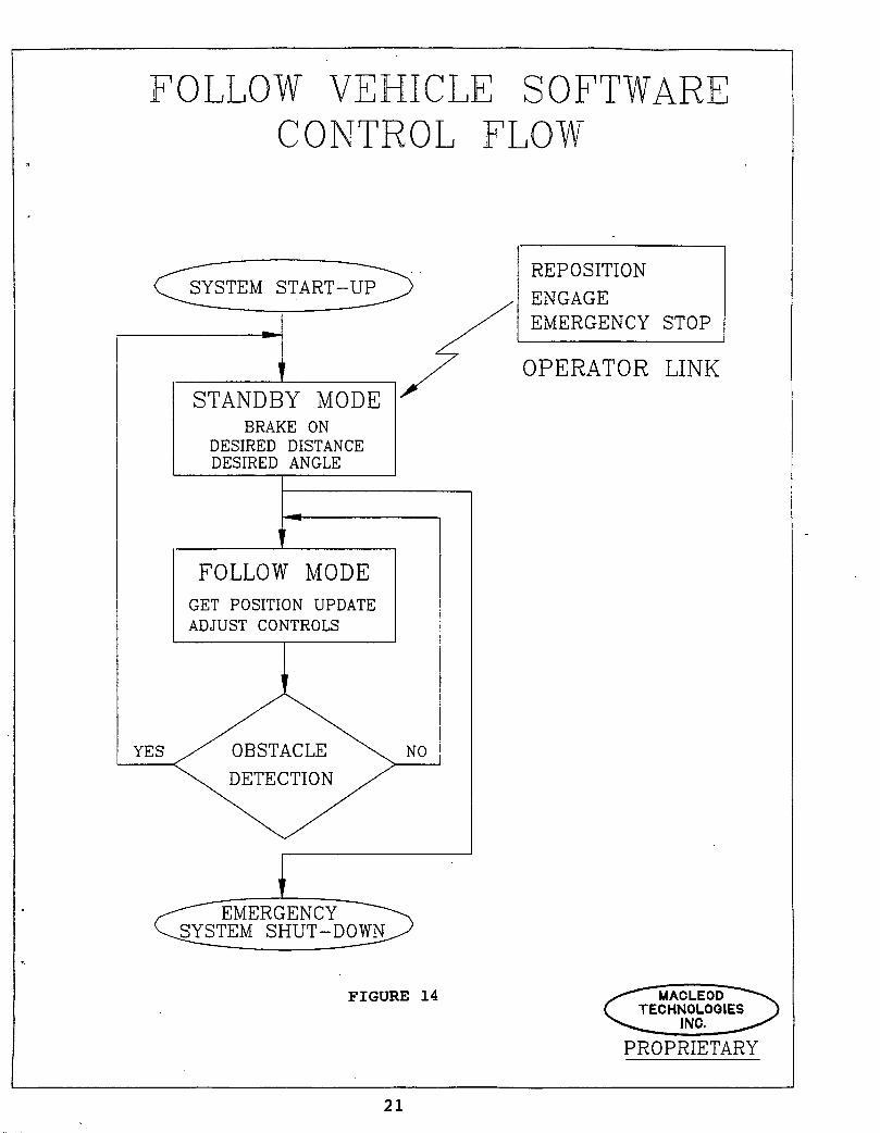
The control flow diagram of the complete automated follow vehiclesoftware system is given in Figure 14. The software containsmodules to acquire follow vehicle navigation data, compute followvehicle position updates from that data, calculate control valuesfor the servo motor assemblies that drive the follow vehicle,
monitor the remote operator control box and check for obstacles.
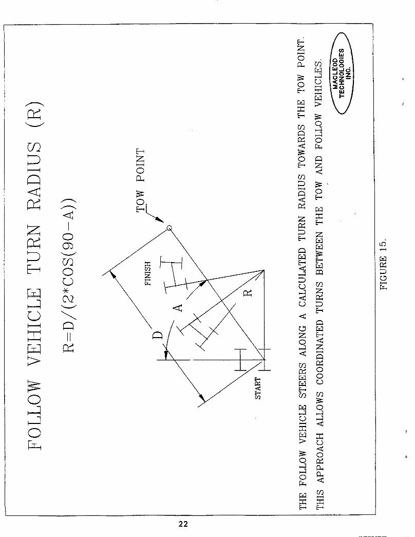
In Follow Mode, control algorithms adjust steering, throttle andbrake servos in a smooth and human-like fashion. Very smooththrottle and brake control was achieved by incorporating a schemeinto the speed control algorithm to jump over the range ofhysteresis in the floor pedals. Steering was performed accordingto a follow vehicle turn radius model. The vehicle turn radiuslimits the lateral motion of the follow vehicle. Figure 15illustrates the follow vehicle turn radius computation. Thismodel has been proven to provide smooth control over steering.The follow vehicle does not steer directly towards the tow point,but follows the calculated turn radius towards the tow point.A turn radius is calculated for every follow vehicle position
update (25 times per second max).
18

AUTOMATED FOLLOW VEHICLE SIMULATION_ MACLEOD TECHNOLOGIES INC.
400
300 - " "
T200 -
100 -
i
0 I I i I f0 100 200 300 400 500 600
FEET
TOW VEHICLE PATH FOLLOW VEHICLE TRACK
50 FEET FOLLOW DISTANCE WITH 10 DEGREE OFFSET.
FIGURE 12. AUTOMATED VEHICLE SIMULATOR
This figure represents a screen from the Phase I automatedvehicle simulator. Follow control algorithms were developed andtested using the simulator before proceeding to reduced-scale andfull-scale implementation. The space between the tow vehicle andfollow vehicle in this figure represents the 10 degree followoffset. The simulator made it possible to quickly test theeffects of changing many control parameters.
19

}
I
FIGURE 13 REDUCED-SCALE FOLLOW VEHICLE
3.6 DESIGN/FABRICATE NAVIGATION CIRCUIT
Computer interface circuits for navigation data acquisition weredesigned to meet the goals of this project. A single boardapproach for follow car navigation and control was accomplished.This board attaches to the portable 386 computer located in thefollow car.
Timing circuits were designed and fabricated that convertincoming OPS signals into clock signals for accurate and reliablenavigation. Digital to analog control circuits to commandsteering, throttle and brake servos have also been fabricated andtested.
Much testing was performed on the Navigation Circuit in bothindoor and outdoor environments. Indoors, the Navigation Circuitperformed at 100% (25 uninterrupted position updates per second).
Outdoors and integrated into the full-scale vehicle,modifications were made to the Navigation Circuitry to isolatethe board from system electromagnetic interference. Allsusceptible cabling was shielded and opto-isolators wereincorporated in the Navigation Circuitry to completely isolatethe onboard computer from the rest of the system. All externalwiring uses common and reliable modular style connectors.
20
FOLLOW VEHICLE SOFTWARECONTROL FLOW
REPOSITION
_SYSTEM START-UP _ ENGAGE
"i _ EMERGENCY STOPOPERATOR LINKSTANDBY MODE
BRAKE ONDESIRED DISTANCEDESIRED ANGLE
FOLLOW MODE
GET POSITION UPDATE
ADJUST CONTROLS
YES NO
/...---'---'-'_-ME RGE NCy_'_'-'_-_.__-...SYSTEM SHUT-D0WN/'
T.
FIGURE 14
PROPRIETARY
21

3.7 DESIGN/FAB OPTO-ELECTRONIC POSITION SENSORS (OPS)
Opto-electronic Position Sensors (OPS) were designed andfabricated to meet the range, weather and mounting requirementsof this application. Field of view for opto-electronics is ii0degrees laterally allowing the specified +/- 45 degree vehicle to
• vehicle operation. Solar rejection and sensitivity is excellenteven in direct sunlight. The OPS are shown mounted on the full-scale vehicle in Figure 16.
Fast switching infrared sensitive diodes were used to providemaximum sensitivity to the laser wavelength of the MOB whileproviding maximum rejection of other wavelengths. Three OPScomponents are mounted on the front bumper of the automatedtraffic control vehicle. The OPS transmit electronic pulses tothe navigation timing circuitry in the on-board laptop controlcomputer, signaling detection of the MOB energy. Precise followcar position and bearing data relative to the tow vehicle areachieved by advanced trigonometric calculations on the precisetiming waveforms triggered by the OPS pulses as outlined inSection i.
3.8 DEVELOP SAFETY AND HUMAN INTERFACE SYSTEMS
All proposed safety systems were completed with completion of thesoftware obstacle detection algorithms and fail-safe brakeactuator/ignition cutoff circuitry. Obstacle Detection wasaccomplished using the optical beam contact between the MOB andOPS. This method of obstacle detection has been termed the
"electric eye". An obstacle detection array is created by thenavigation components between the tow and follow vehicles as wasshown in Figure 2. This electric eye obstacle detection approachwas demonstrated on the software debug vehicle and response toobstacles was seen to be near instantaneous. Response in full-scale qualification testing was also seen to be nearinstantaneous.
The hand-held remote control box shown in Figure 17 wasfabricated to allow the driver of the tow vehicle to perform anemergency shut-down of the automated vehicle. In addition to theemergency shut-down, the remote box allows the driver toreprogram the tow distance and relative angle to tow of theautomated vehicle. The Emergency shut-down button is the big redbutton on the control box. When pressed it triggers the safetybrake to release and cuts off the vehicle ignition.
The remote hand-held control box is the only operator interfaceto the follow vehicle. To reposition the follow vehicle, thedriver simply throws the REPOSITION-ENGAGE toggle switch toREPOSITION. The hand-held device transmits a code to the
computer to stop the towed car and standby for new followcoordinates. The driver then repositions his tow vehicle to thenew tow configuration (distance and relative angle) and then
23

FIGURE 16. OPS MOUNTED ON FULL-SCALE FOLLOW VEHICLE.
FIGURE 17. REMOTE OPERATOR CONTROL BOX FOR MANUAL CONTROL.
24

switches the toggle switch to ENGAGE. The computer in the towedvehicle immediately computes the bearing and distance to the towvehicle and uses this new distance and offset data to shadow the
tow vehicle. The small red button in the upper right corner ofthe box is to check the unit's battery. The unit is wireless andrechargeable.
3.9 BENCH TEST SYSTEMS
Hardware system bench testing was performed throughout the entireproject to refine system prototype designs and to provide testedhardware subsystems to aid in software debugging.
3.10 REDUCED-SCALE TRIALS
Reduced-scale trials were performed in Phase I to test computermodels and algorithms in a controlled environment. It wasdesirable to test and debug software on a reduced-scale vehiclefor obvious safety and convenience reasons. The reduced-scaletest vehicle shown in Figure 13 was built to meet the needs ofthe reduced-scale trials in this effort. The vehicle carries the
laptop computer and performs the function of the towed vehiclebut at a reduced scale. The maximum speed of the vehicle isequivalent to a brisk walk. This vehicle allows up to 4 hours ofcontinuous operation from a single recharge.
3.11 FIELD TRIALS
Vehicle servo motors and navigation systems were tested outdoorson the full-scale test vehicle. Initially, manual joystickcontrol was used with human driver input. The servo motorcomponents tested most satisfactorily during joystick operatedcontrol. Field testing was performed on a rural street settingwith a driver on standby at all times. No human override wasnecessary.
Computer control over the vehicle servo motors was later testedon the full-scale vehicle. Control algorithm parameters forsteering, brake and throttle were adjusted for optimalperformance. For safety reasons, all prototype testing wasconducted with a standby driver in the automated vehicle. Nohuman override was necessary during field trials.
25
4.0 PHASE I QUALIFICATION TESTING
Qualification testing was performed during reduced-scale testingand full-scale testing to demonstrate Phase I goals andobjectives. Phase I qualification testing emphasizes full-scaleautomated follow vehicle system performance.
4.1 QUALIFICATION TEST SET-UP
Full-scale qualification testing took place on a taxi-way atHanscom Airport in Bedford, MA (see Figure 18). The tow andfollow vehicles are shown in Figure 19. The tow vehicle isfitted with the MOB on its rear bumper as shown in Figure 11. A
12V battery was used to power the MOB. The follow vehicle isfitted with three OPS on its front bumper as shown in Figure 16.
The follow vehicle is also fitted with MTI-designed servo motors
for steering, throttle and brake control. All follow componentsincluding the onboard computer are powered by the follow vehiclebattery. A human driver was present during qualificationtesting. However, human override was never required.
The follow speed was limited to 5 MPH during the full-scalequalification tests. This satisfies the Phase I goal that followvehicle speed will automatically match tow vehicle speed up to 5MPH. Because MTI's CONAC system provides telemetry on followvehicle position updates at such a fast rate (typically 20updates per second), much higher follow speeds can be achieved.In fact, higher speeds are desirable. The 5 MPH limitation onfollow speed required frequent brake throttle manipulation. Athigher speeds only throttle corrections would be required, whichwould enhance the smoothness of speed control.
The calibration targets on the side of the follow and towvehicles were used for photo analysis of the test. The targetsare spaced 12' (3.66 m) apart on the follow vehicle. The targetsare visible in Figure 2.
4.1.1 QUALIFICATION SYSTEM START-UP PROCEDURE
The System Start-Up procedure is as follows:
STEP 1) start the follow vehicle engine,STEP 2) turn on the onboard computer (the follow vehicle is now
in Standby Mode),STEP 3) switch to REPOSITION on the remote control box (this
sets the follow distance and relative follow angle fromthe tow vehicle),
STEP 4) switch to ENGAGE on the remote box (the follow vehicleis now in Follow Mode). If any obstacles are detectedwhile the follow vehicle is in Follow Mode, then thefollow vehicle returns to Standby Mode.
26

FIGURE 18. FINAL PHASE I QUALIFICATION TEST SITEHANSCOM AIRPORT, BEDFORD, MA. MARCH 1993.
_"T[, -- .................
• FIGURE 19. FULL-SCALE TOW AND FOLLOW VEHICLES.
27
4.1.2 QUALIFICATION SYSTEM OPERATION
In Standby Mode the follow vehicle brakes are fully engaged andthe throttle is completely off. The steering control is notaffected by switching between Standby and Follow modes ofoperation. The operator remotely executes the REPOSITION-ENGAGEsequence from his hand-held remote control box.
In Follow Mode, follow vehicle position updates are received 25times per second using a MOB operating at 3000 RPM. Theseposition updates are incorporated into a feedback control loop tocalculate the brake, throttle and steering commands to drive thefollow vehicle. Extensive computer modeling to test the numerousdifferent control approaches was performed in Phase I.
The approach chosen for full-scale qualification testingincorporates the relative velocity and acceleration of the followvehicle with respect to the tow vehicle for speed control.Steering control incorporates the turn radius method illustratedin Figure 15.
The qualification test results presented in this sectionemphasize results collected during an outdoor qualification testat Hanscom Airport in Bedford, MA.
4.2 VEHICLE TRACKING TEST RESULTS
The performance of the system navigation components, the MOB andOPS, is presented in terms of vehicle tracking accuracy in Figure20. The vehicle tracking accuracy is a good indication of CONACperformance since high quality incoming data from the sensorsubsystem is required for accurate vehicle tracking. Documentedoperation up to 120' (36.57 m) in all weather and lightingconditions was achieved. The low standard deviations in Figure20 in both Distance To Tow and Angle To Tow measurements reflectreliable vehicle tracking operation even at very long ranges.
4.3 FOLLOW CONTROL TEST RESULTS
The Phase I goal stated that distance accuracy between the towvehicle and the follow vehicle will be maintained within +/- 5%of follow distance. Reduced-scale testing has been demonstratedto perform well within this limit with a maximum follow distanceof 100' (30.48 m).
Figure 21 shows telemetry data of the follow vehicle's distanceto the tow point (i.e., the MOB on the tow vehicle) for a typicalqualification test run. The data was collected over a 1 minutespan of the test. The variability in the follow distance is seento be +/- 5.4% of the follow distance. The approximate speed ofthis test run was 5 MPH. All follow control tests exhibitedsmooth coordinated control of throttle and brake.
28

VEHICLE TRACXING PERFDRblANCE
MEAN STANDARD KEEP DISTANCE
DEVIATION RATIO (FT.)
ANGLE TO TOW (DEG.) 1.84 1.48
0.889 60
DISTANCE TO TOW (FT.) 60 0.098
ANGLE TO TOW (DEG.) 19.7 0.065
0.336 100
DISTANCE TO TOW (FT.) 96.866 0.134
ANGLE TO TOW (DEG.) 27.5 0.09
0.298 120
DISTANCE TO TOW (FT.) 109.23 0.108
PROPRIETARY
FIGURE 20.
Figure 20 summarizes Vehicle Tracking Performance over anincreasing range in follow distance. Follow distances range from60' to 120'. The Keep Ratio reflects the number of positionupdates used by CONAC to control the follow vehicle. At a 60'follow distance, for example, approximately 9 out of 10 positionupdates are used. The measures of performance are Distance ToTow and Angle To Tow. Distance To Tow is the distance along astraight line between the MOB and the middle OPS. Angle to Towis the angular offset of the follow vehicle in relation to acenterline from front to rear of the tow vehicle. The MOB laser
power used was 5 milliwatts and MOB rotation speed was 3000 RPM.
29

DISTANCE TO TOW VS TIME ,i
MACLEOD TECHNOLOGIES INC.6O
4.
5O
40
0 30
r.r.1r..)
20[-
10
00 10 20 30 40 50 60 70 80
"rIME (SECONDS)
FIGURE 21. FOLLOW DISTANCE TEST RUN
The data presented in this graph was collected during Phase IQualification Testing at Hanscom Airport, Bedford, MA. The data
were acquired using a .5 second sample rate during a typical
follow run. The follow speed was approximately 5 MPH. Thenavigation circuitry and software generated 25 relative positionupdates per second. All 25 updates every second were used incontrolling the follow vehicle. Follow distance accuraciesbetter than +/- 5.4% of the follow distance were achieved.
30
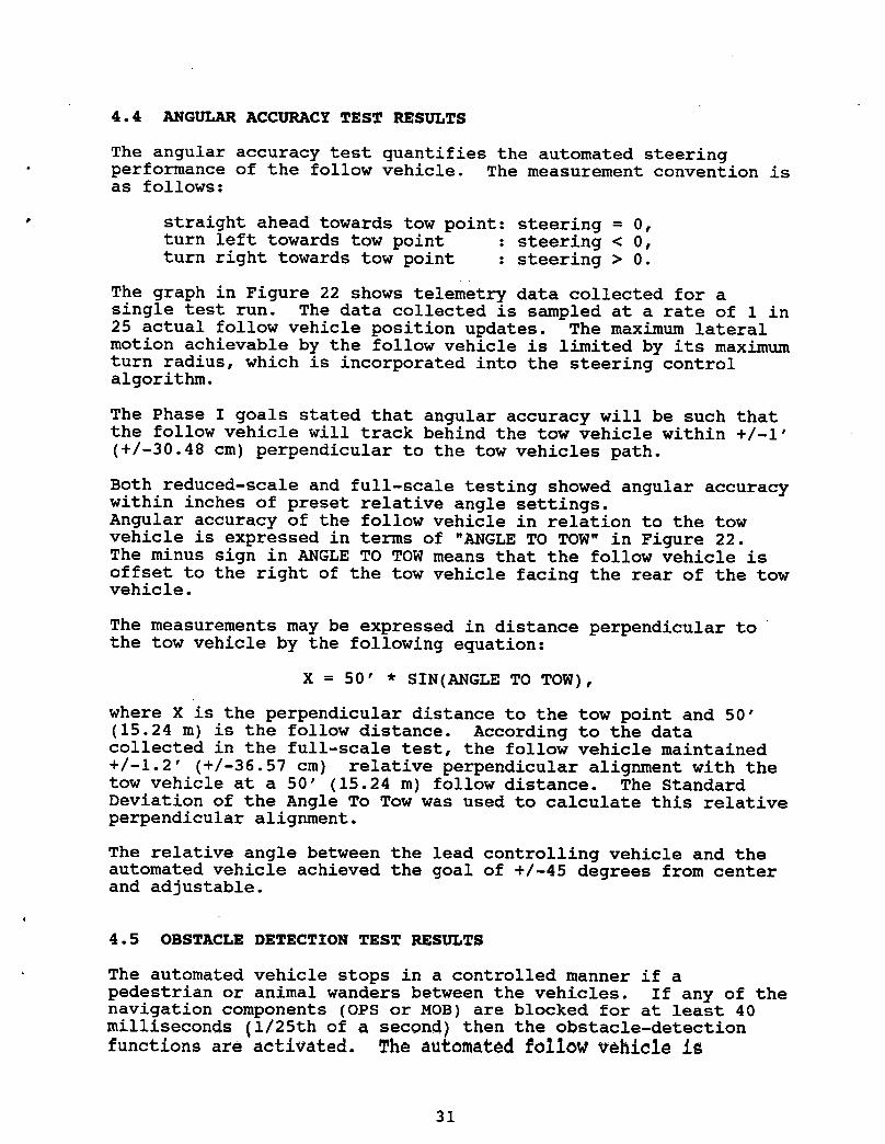
4.4 ANGULAR ACCURACY TEST RESULTS
The angular accuracy test quantifies the automated steering• performance of the follow vehicle. The measurement convention is
as follows:
0 straight ahead towards tow point: steering = 0,turn left towards tow point : steering < 0,turn right towards tow point : steering > 0.
The graph in Figure 22 shows telemetry data collected for asingle test run. The data collected is sampled at a rate of 1 in25 actual follow vehicle position updates. The maximum lateralmotion achievable by the follow vehicle is limited by its maximumturn radius, which is incorporated into the steering controlalgorithm.
The Phase I goals stated that angular accuracy will be such thatthe follow vehicle will track behind the tow vehicle within +/-i'
(+/-30.48 cm) perpendicular to the tow vehicles path.
Both reduced-scale and full-scale testing showed angular accuracywithin inches of preset relative angle settings.Angular accuracy of the follow vehicle in relation to the tow
vehicle is expressed in terms of "ANGLE TO TOW" in Figure 22.The minus sign in ANGLE TO TOW means that the follow vehicle isoffset to the right of the tow vehicle facing the rear of the towvehicle.
The measurements may be expressed in distance perpendicular tothe tow vehicle by the following equation:
X = 50' * SIN(ANGLE TO TOW),
where X is the perpendicular distance to the tow point and 50'(15.24 m) is the follow distance. According to the datacollected in the full-scale test, the follow vehicle maintained+/-1.2' (+/-36.57 cm) relative perpendicular alignment with thetow vehicle at a 50' (15.24 m) follow distance. The StandardDeviation of the Angle To Tow was used to calculate this relativeperpendicular alignment.
The relative angle between the lead controlling vehicle and theautomated vehicle achieved the goal of +/-45 degrees from centerand adjustable.
4.5 OBSTACLE DETECTION TEST RESULTS
The automated vehicle stops in a controlled manner if apedestrian or animal wanders between the vehicles. If any of thenavigation components (OPS or MOB) are blocked for at least 40
milliseconds (i/25th of a second) then the obstacle-detectionfunctions are activated. The automated _ollow vehicle is
31

ANGLE TO TOW VS TIMEtD MACLEOD TECHNOLOGIES INC. .,m 40
>,30I-
N 2o
_: lO©
_D -10
i -20-30
r_
eq -40
Z 0 10 20 30 40 50 60 70 80TIME (SECONDS)
NOTE: THIS REPRESENTS TELEMETRY DATA ONLY AND DOES NOT REFLECTLATERAL VEHICLE MOTION.
FIGURE 22. RELATIVE ANGLE TEST RUN
The graph in Figure 22 depicts the control data used by thefollow vehicle to maintain a fixed angular offset from the townvehicle. The data does not reflect the instantaneous lateralmotion of the follow vehicle. The data shows that the followvehicle maintained a follow offset of zero degrees which meansthat the follow vehicle followed directly behind the townvehicle.
32

immediately stopped and enters Standby Mode, where it awaits theReposition signal from the remote control operator box. Theobstacle detection functions worked reliably in both indoors andoutdoors testing.
• 4.6 QUALIFICATION TEST SUMMARY
In summary, qualification testing was extremely successful. Froma passenger's viewpoint in the automated follow vehicle, the ridewas smooth and on-track. The data acquired by MTI's navigationsystem were accurate and reliable. The steering, throttle andbrake control algorithms exhibited human-like driving over theautomated follow vehicle.
33
5.0 PHASE I CONCLUSIONS AND RECOMMENDATIONS
5.1 CONCLUSIONS
The automated follow vehicle concept demonstrated has been provento be accurate, reliable and safe. The navigation systemacquired very accurate Distance To Tow and Angle To Towmeasurements in both indoor and outdoor conditions. All safetysystems operated as expected. Overall, the Phase I automatedfollow vehicle system exhibited outstanding performance, meetingand in most cases exceeding Phase I goals.
5.2 RECOMMENDATIONS FOR FUTURE DEVELOPMENT
Cursory recommendations are provided in this section for furtherdevelopment of the automated follow vehicle concept. Therecommendations presented here reflect lessons learned from PhaseI. A more comprehensive treatment on future development would begiven in a formal Phase II proposal.
5.3 CONTROL SOFTWARE ENHANCEMENTS
Control algorithm parameters should be optimized to maximizeControl system performance. Responsivity of the control systemmust be fast enough to maintain smooth control over the followvehicle. The algorithm parameters that control speed of thefollow vehicle were discussed in Section 3.5. An automatedcalibration routine for maintenance workers to use should be
included. This calibration procedure may be executed once at thebeginning of a work session or it may be necessary to adjust theparameters as the vehicle warms up or weather conditions change.
5.4 VEHICLE SERVO MOTORS ENHANCEMENTS
A manual override switch is desirable to disengage steering servomotor control to allow normal manual operation of the steeringwheel. This would facilitate repositioning of the follow vehicleby a human driver. The vehicle processor would enter StandbyMode when this occurs and await repositioning by the remoteoperator control box. A single lever would alternate betweenmanual and automated modes of operation. This is much moreoperator-friendly than removing the steering motor assembly everytime the follow vehicle is repositioned.
In Phase I, the anti-rotation steering servo arm was placed fromthe steering wheel to the brake box on the driver side floor asseen in Figure 9. This rod should be moved to connect to thedashboard behind the steering wheel. This would facilitate ahuman driver getting in and out of the automated vehicle.
34

5.5 ALL-WEATHER TESTING
Satisfactory CONAC performance was observed in many outdoorconditions. Hard data, however, was not obtained in this effortwith weather as the only variable. Further testing isrecommended. System tuning and testing was performed in brightsunlight, clouds, heavy rain, 2 inch/hour (5.08 cm/hour) snow,sleet, and night-time conditions. Neither the system hardwarenor the system electronics suffered any damages due to thevarying weather conditions. No conditions rendered the CONACsystem inoperable. Bright sunlight was observed to cause slightdegradation in system range of operation. MTI is currentlydeveloping improvements to the CONAC sensors to increase theirrobustness in bright sunlight. Unfortunately these enhancementswere not available at the time of testing. Development andexecution of a Test Plan to quantify the individual effects ofvarying weather conditions on system performance is recommended.
Further development in weather-proofing navigation OPS and MOBsshould include incorporating a tiny thermostatically controlledheater in each component. The heater should activate below 34degrees Fahrenheit. This heater would melt snow and icecollected on the OPS or MOB and control humidity in the devices.
35
6.0 COMMERCIAL APPLICATIONS
AS a result of Phase I, commercial potential of the automatedfollow vehicle application were explored. Authorities at the _Central Tunnel Artery Project in Boston, MA expressed highinterest in the automated follow vehicle as a potential solution
to many tunnel-related applications. Specific applications werei. to enhance work crew safety in the tunnel, 2. to automatethe water tank truck that follows the tunnel washer to refill thewasher, and 3. to provide automated follow vehicles to protectthe water tank follow truck. Due to the restricted space in thetunnels, a follow vehicle would protect work crews as is itsintended purpose. Due to the late night hours during whichtunnel washing takes place, the human drivers are at risk ofbeing hit by drunk and/or drowsy drivers.
6.1 COLLISION-PREVENTION SPIN-OFF
The technology proven in this effort is an excellent match forcollision prevention for manned vehicles. The technologysignificantly exceeds the capabilities of existing collisionprevention techniques presentlybeing researched. The precisevehicle to vehicle position awareness makes it possible for anonboard computer to predict impending collisions with othervehicles. If a bearing to a vehicle is constant and closure rateis computed to be excessive, the computer could actuate thebrakes. In a head on collision, both vehicles would beoverridden. To avoid system confusion in heavy traffic, computercontrolled OPS sensitivity would reduce data to only the nearestvehicles. Obviously, research is necessary to test decisionalgorithms and hardware.
It is possible for this equipment to be added to any vehicle on arelatively low cost aftermarket basis. For the approach to work,all vehicles must be equipped. The end result however would bethe elimination of head on collisions, rear end collisions andintersection collisions. Even collisions from sleeping or drunkdrivers could be prevented.
36

7.0 ABBREVIATIONS
CONAC Computerized Opto-electronic Navigation and ControlDPW Department of Public WorksMOB Mobile Opto-electronic BeaconMTI MacLeod Technologies IncorporatedOPS Opto-electronic Position SensorRPM Rotations Per Minute
e
37