Automated Tissue Microarrayer
49
Quick Ray ® Master UATM-272B User Manual 1 Automated Tissue Microarrayer (Model UATM-272B) V.01070417
Transcript of Automated Tissue Microarrayer

Quick Ray® Master UATM-272B User Manual
1
Automated Tissue Microarrayer (Model UATM-272B)
V.01070417
Quick Ray® Master UATM-272B User Manual
2
NOTE This User Manual describes the installation and operation of Quick Ray Master UATM‐272B (referred to as ‘Instrument’ hereinafter). Please review this manual to avoid injury and prevent damage to this instrument or any products connected to it before you operate. To avoid potential hazards, operate this instrument only as specified in this manual. This manual contains information and warnings that must be followed by the user to ensure safe operation and to maintain the instrument in a safe condition. User shall be responsible for paying all shipping charges, duties, taxies, and any other charges for any failure or damage or injury caused by improper use or improper or inadequate maintenance and care. Unitma Co., Ltd. shall not be obliged to furnish service under this case, a) to repair damage resulting from attempts by personnel other than Unitma Co., Ltd. representatives to install, repair or service the products , b) to repair damage resulting from improper use or connection to incompatible equipment, c) to repair any damage or malfunction caused by the use of non‐Unitma Co., Ltd supplies, or d) to service a product that has been modified or integrated with other products when the effect of such modification or integration increases the time or difficulty of servicing the product. Copyright© Unitma Co., Ltd. All rights reserved. Licensed products are owned by Unitma Co., Ltd., and are protected by national copyright laws and international treaty provision. Unitma Co., Ltd. products are covered by patents, issued and pending. Specifications and price change privileges reserved. Quick RayTM is the registered trademark of Unitma Co., Ltd. All information is subject to change without prior notice. Contact to : Unitma Co., Ltd. 102, Saehan B/D, 5, Bokjeong‐ro, Sujeong‐gu, Seongnam‐si, Gyeonggi‐do, 13119, Korea Tel : +82 31 721 8003 / +82 2 420 0070 Fax: +82 31 751 8003 e‐mail :[email protected] website : http://www.unitma.com

Quick Ray® Master UATM-272B User Manual
3
Contents
1. IMPORTANT NOTES………………………….....…………...…….………….…………..…..5 1.1 Explanation of Symbols…............................................................................5 1.2 Qualification of personnel…........................................................................5
2. SAFETY NOTES…..………………………………….……………………..………….……………5
3. COMPONENTS AND SPECIFICATIONS OF THE INSTRUMENT…....…….………7
3.1 Outline…..…………..………….…..…….…………………….….…………….….………………..7 3.2 Instrument component..……….…………………………..….………….…………………..8 3.3 Structure……………………………………………………………………………………………….9 3.3.1 Requirements of HW and SW………………………………………………………………………9 3.3.2 Controller..……………….……….….………………………………….……...……….…………….…9 3.3.3 TARP(Excel Data) file..……..……..…………………………..……….….……….………….…….9
3.4 Instrument Specifications and Features………………………………………………….10
4. INSTALLATION OF THE INSTRUMENT…..…..………..….…………………………….11 4.1 Site requirements.......……………...……………………….…..….……………..………….11 4.2 Connection with PC…………….…….……………………….………..………..……….…….12
5. SET UP….………………………………………...………………………….………………………13 5.1 Set up Procedure......................................................................................13
5.1.1 Tip Body Parameter………..……...……….……………………….……………………………….14 5.1.2 Calibration Parameter……………………….………………………….……………………………17 5.1.3 Marker Parameter........................................................................................22 5.1.4 Recipient Hole Parameter…………….…………………………….………………………………24
6. OPERATION………………….…….……………………….……………………………………..26 6.1 Main menu…………………………………………..…………………………………………………26 6.1.1 Demo…………………………………………………………..…………………………..…………………26 6.1.2 Auto……………………………………………………………………………………………………………26 6.1.3 Description of each menu…..……………………..….………….….…………………………….27 6.1.4 Set………………………………………………………………………………………………………………27 6.1.5 Exit..……………………………………………………………………………………………………………27
6.2 Installation of Puncher module………….…………..…...…….….……………………….28 6.3 Preparation before running instrument…………....……………..…………………….30 6.4 Start to run(UATM.EXE)…………………………………………..……………………………..32 6.4.1 Click ‘AUTO’menu…………………………………….………………………………………….……..32 6.4.2 Load File……………………………………………………………………………………………………..33 6.4.3 Select Recipient Block...................................................................................34 6.4.4 Set Tray……………….………………………………………………...…………….…………………….34 6.4.5 Start TMA work…………………………………….…………….…..…..…………………..………..34

Quick Ray® Master UATM-272B User Manual
4
6.4.6 Stop TMA Work & Consecutive work.……….…….….…..……..…………………………..38 6.4.7 Teaching mode..……………….…………………….………….…..……..…………………………..40
6.5 Manual mode………………………….…………..…………….....…………….………………..42
7. TROUBLE SHOOTING..….………..……………………………………………………………45
8. CLEANING & MAINTENANCE..…….……………………………………………………….47 8.1 Cleaning the instrument……….…………..……………………………………………………47 8.2 Consumables …………….…………..…………….……………………………….……………….47 8.3 Maintenance………………………..…………….…………..……………………….…………….48 8.3.1 Checking the instrument…………………………………....……………………………………...48
8.4 Repair……………………………………………….…………………….……………………………..48
9. WARRANTY & SERVICE…………….………………………………………………………….48 9.1 Terms & Conditions………………………………….……..……………………………………..48 9.2 The Warranty does not cover…………………………………….……………………………49 9.3 Contact for technical service.………………………………………………………………….49

Quick Ray® Master UATM-272B User Manual
5
1. IMPORTANT NOTES 1.1 Explanation of Symbols
1.2 Qualification of personnel
2. SAFETY NOTES
READ THE FOLLOWINGS BEFORE USING THE INSTRUMENT
CAUTION: CAUTION indicates a hazard not immediately accessible as you read this symbol. It calls attention to an operating procedure, practice, or the like, that if not correctly performed or adhered to, could result in damage to the product or loss of important data. Do not proceed beyond a CAUTION notice until the indicated conditions are fully understood and met.
The Quick Ray Master UATM‐272B should be operated by trained histopathology laboratory personnel. All laboratory personnel designated to operate UATM‐272B is required to read this entire manual before operating UATM‐272B. The use of the instrument for any other purpose than originally intended may damage the instrument or injure the user and will void all warranties. Keep the puncher tip clean and do not use the instrument if there are foreign things (silk fiber, stapler pin, calcification tissue, bone and teeth) in the puncher tip.
Read the following safety notes to avoid injury and prevent damage to this instrument or any products connected to it. Misuse of electrical equipment can cause electrocution, burns, fire and other HAZARDS.
• Observe all warnings and instructions.
• Observe all Terminal Ratings. To avoid fire or shock hazard, observe all ratings and markings on the instrument. Consult the manual for further ratings information before making connections to the instrument.
• Power Disconnection. The power switch disconnects the instrument from the power source. See instructions for the location. Do not block the power switch; it must remain accessible to the user at all times.
• Regularly inspect the AC power cord for damage and for dust build‐up around the power plug or electrical outlet.
• Stop operation and unplug the AC power cord from the electrical outlet and disconnect any other cables immediately in the following cases ; when the instrument functions in an abnormal manner, produces unusual sounds, if there is unpleasant or offensive odor, and becomes too hot to touch.
• Do not operate when the front door of the instrument is opened. Close the front door before operating the instrument.

Quick Ray® Master UATM-272B User Manual
6
Using in proper environment
To avoid personal injury
Use the instrument and accessories according to the instructions in this manual
.
• Provide proper ventilation. Refer to the manual’s installation instructions for details on installing the instrument so it has proper ventilation.
• Do not expose the instrument or accessories to high temperatures, high humidity, or direct sunlight.
• Do not expose the instrument or accessories to dust, smoke or steam.
• Do not place the instrument on surfaces that are tilted, unstable or subject to vibration.
• Do not put heavy objects on the instrument or accessories.
• Do not use the instrument where oxygen gas is used.
• Be careful not to compress your fingers when closing the front door of the instrument.
• Use in a well illuminated area and keep the LCD screen in a safe distance from your face.
• Keep the front door of the instrument in a safe distance from your head and face.
• Do not operate without covers. Do not operate this instrument if covers or panels are removed.
• Keep the instrument and accessories out of the reach of children.
• Do not touch the plug of the AC power cord with wet hands.
• Be careful with your fingers or hands from being injured while assembling or disassembling the tip body or the block holder frame, or when cleaning the interior of the instrument.
• Use the instrument and accessories according to the instructions in this manual. Neither authorization for the analysis or modification of the instrument, nor the analysis and use of its circuit configuration, is provided.
• Never disassemble the instrument or supplied accessories. Disassembling will void the instrument warranty. Additionally, there is a risk of fire, electrical shock or malfunction.
• Do not use accessories that are not supplied or recommended by Unitma Co.,Ltd.
• Contact Unitma Co., Ltd. for repairing service or to purchase accessories.

Quick Ray® Master UATM-272B User Manual
7
3. COMPONENTS AND SPECIFICATIONS OF THE INSTRUMENT
3.1 Outline The instrument is an automated tissue microarrayer which extracts tissue samples from donor blocks and delivers the extracted tissue samples into recipient blocks automatically. To perform this function, two sets of cameras and 4 axis motion controllers are equipped. With the aid of donor block dedicated camera, a tip extracts the tissue from the target point marked with an ink pen on donor blocks and delivers the extracted sample tissue into a recipient block area. Then, the recipient block dedicated camera detects the center of corresponding hole and inserts the tissue sample into the hole of the recipient block. This automatic process can be done by defining 3 parameters (size of punch, number of donor blocks, and sample number per donor block) with ‘TARP’ (Tissue Array Report Program) of Excel data file which is already installed in the PC. After the process, information of inserted tissue into recipient block is revised and saved in ‘TARP’ file. This ‘TARP’ file is in Excel file format which is useful for data processing, managing database and others. The premade recipient block (UB06) to be supplied by UNITMA Co., Ltd. should be used. The recipient block (UB06) patented in global is made of special materials that melts when heated at 70°C for 30 minutes and has premade, evenly spaced round wells arranged in a square matrix. Therefore, UNITMA premade recipient block will save the conventional‐block building time and guide the pathologists to fully utilize the power of TMAs. Tissue Microarray (TMA) : Tissue Microarrays are a collection of multiple tissue cores that are arranged in columns and rows inside a paraffin block allowing for histological analysis. They are a crucial tool in the analysis of gene and protein expression levels in samples from normal and diseased specimens. Further, they are useful in the early‐stage discovery of gene targets in genomic research, validating targets, testing and optimization of diagnostic tests, and in the quality control of molecular detection schemes. And the ‘Tissue array’ technology not only makes decrease the reagent, time and human resource below one sixtieth but also can be applied to most of the know‐how about tissues for immunohistochemistry, in situ hybridization, FISH and in situ PCR.

Quick Ray® Master UATM-272B User Manual
8
3.2 Instrument component
<Outside view of the instrument>
<장비의
<Inside view of the instrument>
<Left view of the instrument>
Right side cover
Power inlet Main power switch USB
Emergency Stop button
Tray door
Front door
1. Puncher Module 2. Puncher (0.5mm, 1mm, 1.5mm and 2mm) 3. Camera 1 4. Camera 2 5. Front door sensor 6. Main plate 7. Donor block tray 8. Recipient block holder tray
Left Window

Quick Ray® Master UATM-272B User Manual
9
3.3 Structure The instrument is composed of 2 cameras, 4 axes of mechanical parts controlling by PC. Two cameras are for detecting donor blocks and recipient block areas respectively. The 4 axes motion controller consists of X, Y, Z, P axis. X, Y and Z is for the basic movements of the instrument while P axis is for the sample tissue extraction/insertion. Y axis is for main plate (for donor and recipient block) to move along +, ‐ direction. The head unit containing cameras and tips moves along X and Z axes. The combination of the above two movements enables X, Y, Z ‐ 3 dimensional movements. 3.3.1 Requirements of HW and SW
Hardware CPU Pentium 2.0 GHz as a minimum
HDD 60G as a minimum RAM 1G as a minimum
Software MS Window MS Window 7 Eng.Ver 64 bit MS Excel MS Excel 2016 Eng.Ver
3.3.2 Controller
The control parts consist of the motion controller based on Servo motors, I/O modules and 2 cameras. 4 axes of X, Y, Z, P are connected to motion controller, main program, UATM.EXE, running by Window 7, loads ‘TARP’ Excel files when executed. During operation the current data is saved at ‘TARP’ file automatically in real‐time. 3.3.3 TARP(Excel Data) file
Tissue Array Report Program(‘TARP’) in a standard EXCEL 2016(.xlsx) file form, has the pre‐set values for operating the instrument. After completing the work, a user can acquire the information on the completed recipient block from the ‘TARP’ file.
Quick Ray® Master UATM-272B User Manual
10
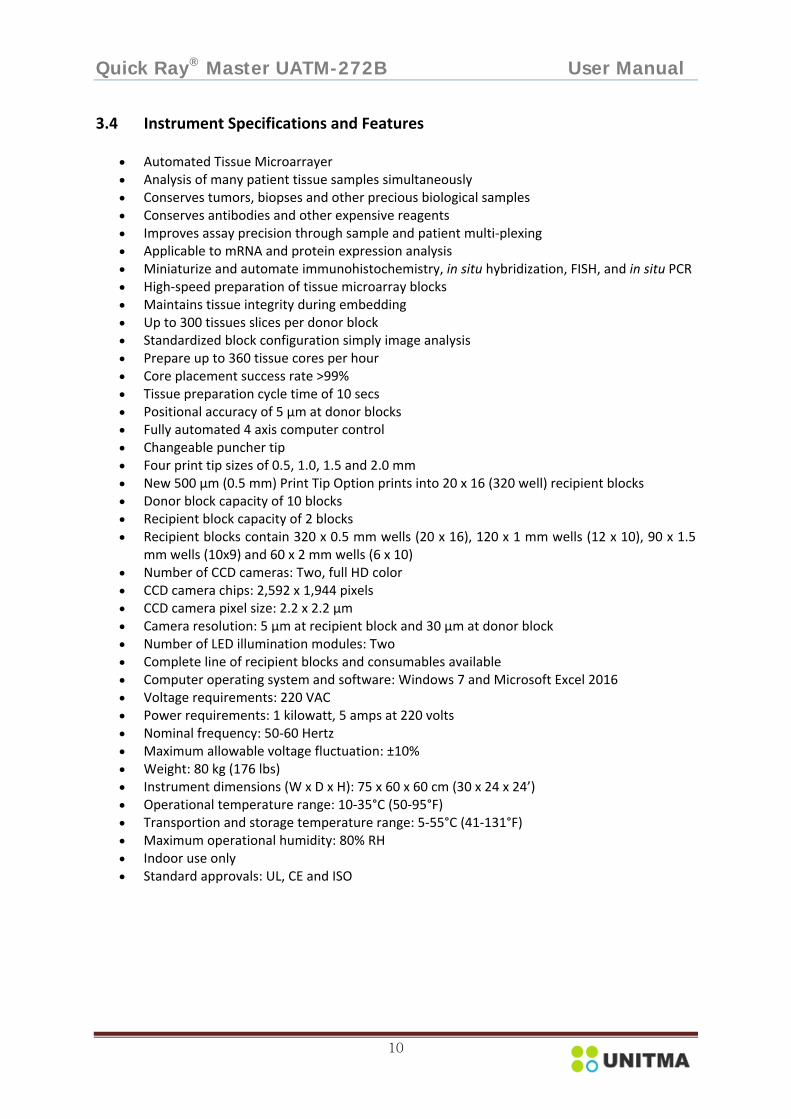
3.4 Instrument Specifications and Features
• Automated Tissue Microarrayer • Analysis of many patient tissue samples simultaneously • Conserves tumors, biopses and other precious biological samples • Conserves antibodies and other expensive reagents • Improves assay precision through sample and patient multi‐plexing • Applicable to mRNA and protein expression analysis • Miniaturize and automate immunohistochemistry, in situ hybridization, FISH, and in situ PCR • High‐speed preparation of tissue microarray blocks • Maintains tissue integrity during embedding • Up to 300 tissues slices per donor block • Standardized block configuration simply image analysis • Prepare up to 360 tissue cores per hour • Core placement success rate >99% • Tissue preparation cycle time of 10 secs • Positional accuracy of 5 µm at donor blocks • Fully automated 4 axis computer control • Changeable puncher tip • Four print tip sizes of 0.5, 1.0, 1.5 and 2.0 mm • New 500 µm (0.5 mm) Print Tip Option prints into 20 x 16 (320 well) recipient blocks • Donor block capacity of 10 blocks • Recipient block capacity of 2 blocks • Recipient blocks contain 320 x 0.5 mm wells (20 x 16), 120 x 1 mm wells (12 x 10), 90 x 1.5
mm wells (10x9) and 60 x 2 mm wells (6 x 10) • Number of CCD cameras: Two, full HD color • CCD camera chips: 2,592 x 1,944 pixels • CCD camera pixel size: 2.2 x 2.2 µm • Camera resolution: 5 µm at recipient block and 30 µm at donor block • Number of LED illumination modules: Two • Complete line of recipient blocks and consumables available • Computer operating system and software: Windows 7 and Microsoft Excel 2016 • Voltage requirements: 220 VAC • Power requirements: 1 kilowatt, 5 amps at 220 volts • Nominal frequency: 50‐60 Hertz • Maximum allowable voltage fluctuation: ±10% • Weight: 80 kg (176 lbs) • Instrument dimensions (W x D x H): 75 x 60 x 60 cm (30 x 24 x 24’) • Operational temperature range: 10‐35°C (50‐95°F) • Transportion and storage temperature range: 5‐55°C (41‐131°F) • Maximum operational humidity: 80% RH • Indoor use only • Standard approvals: UL, CE and ISO

Quick Ray® Master UATM-272B User Manual
11
4. INSTALLATION OF THE INSTRUMENT
4.1 Site requirements
• Transporting the instrument The weight of the instrument is about 80kg. The instrument should not be moved frequently. Before you install the instrument, make ensure that your site is properly prepared so you can avoid having to move the instrument later to accommodate power sources and network connection.
• To transport the instrument safely, take the following step 1) Since the weight of the instrument is over 80kg, four adults are necessary for safe transportation.
2) Minimum 2 people working together should hold each corner of the instrument. 3) Each people holding one corner with both hands should move in coordination. 4) Be careful when moving the instrument to avoid any physical damage.
• Floor requirement Ensure that the floor under the instrument is capable of supporting all other installed instrument. Do not put any objects on the instrument or accessories.
• Positioning the instrument 1) The rear of the instrument must remain unobstructed to ensure adequate airflow and prevent overheating inside the instrument.
2) The interface port in the right side of the instrument is for connecting cables for interfacing external devices by a port for USB. Ensure that connecting cable is not obstructed.
3)The power inlet in the right side of the instrument is for connecting the power cable to AC power source. Ensure that connecting cable is not obstructed.
• Ventilating requirement The air intake and exhaust areas must be free from obstructions. Unrestricted air flow is required for proper cooling. Ensure that air flow is not obstructed. When installing or using the instrument, provide at least 4 inches (100mm) clearance from the instrument for proper cooling.
• Relative humidity (non‐condensing) Operating: 20 to 80% / Storage: 20 to 60%
• Temperature Operating: 10℃ to 35℃ ( 50℉ to 95℉) / Storage: 5℃ to 55℃ ( 41℉ to 131℉) • Do not exposure to direct sunlight. • Do not use an extension cord. • Connection to main power supply.
Interface port Power inlet

Quick Ray® Master UATM-272B User Manual
12
1) Set the AC power switch to the ‘OFF’ position. 2) Refer to ‘Power cords’.
U.K. Europe U.S.A. Switzerland Denmark
3) Connect the power cord (maximum 3m) to the right side of the instrument, then to a suitable AC voltage source. Ensure that you should use a proper power cord.
4.2 Connection with PC
Note 1) Win7(64bit) and Excel 2016 should be installed 2) HDD should be divided by C: drive and D: drive
Steps 1) Please connect the instrument to USB 2.0 port at the PC. 2) Turn on the main switch of instrument and PC switch in order
• A constant and stable AC power source supply to the instrument must be ensured at all times. Failure to comply with this will cause severe damage to the instrument.
• Always use a grounded power cord. Do not use defective power cord.

Quick Ray® Master UATM-272B User Manual
13
5. SET UP The basic procedure of ‘Setup’ is to setup the instrument after log‐in or to select ‘MENU' for checking. Check, adjustment and registration of relevant set value are required for operating the instrument. After log‐in, 7 kinds of setup items are displayed as below. But Users need not to calibrate ‘Donor Block Param’,Recpient Block Param, and ‘Speed Param’ since they were already set at the factory.
5.1 Set up Procedure
Showing ‘Password’pop up
Click ‘SET’ after initialization at the initial screen
Key pad disappears
Key pad pop up
Set up menu
Click ‘P/W’ text box at pop up window
Click ‘OK’ at pop up window
Input ‘A’ on key pad and click ‘OK’
Quick Ray® Master UATM-272B User Manual
14
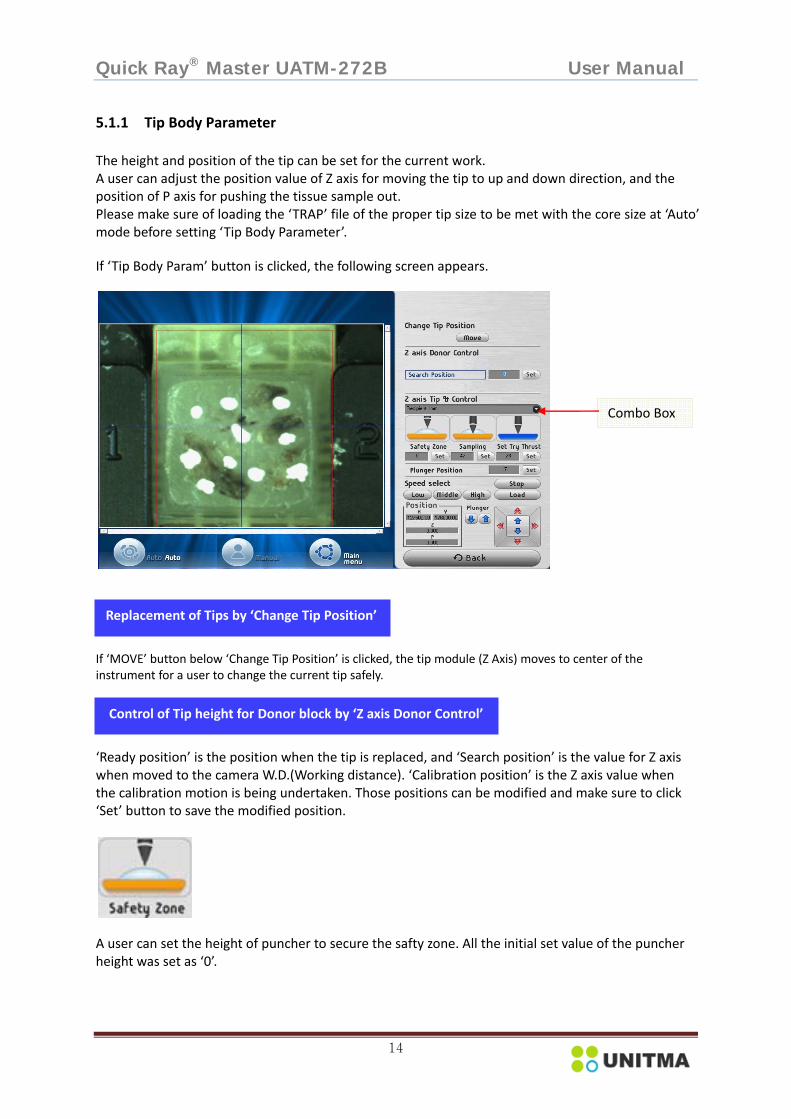
5.1.1 Tip Body Parameter
The height and position of the tip can be set for the current work. A user can adjust the position value of Z axis for moving the tip to up and down direction, and the position of P axis for pushing the tissue sample out. Please make sure of loading the ‘TRAP’ file of the proper tip size to be met with the core size at ‘Auto’ mode before setting ‘Tip Body Parameter’. If ‘Tip Body Param’ button is clicked, the following screen appears.
If ‘MOVE’ button below ‘Change Tip Position’ is clicked, the tip module (Z Axis) moves to center of the instrument for a user to change the current tip safely.
‘Ready position’ is the position when the tip is replaced, and ‘Search position’ is the value for Z axis when moved to the camera W.D.(Working distance). ‘Calibration position’ is the Z axis value when the calibration motion is being undertaken. Those positions can be modified and make sure to click ‘Set’ button to save the modified position.
A user can set the height of puncher to secure the safty zone. All the initial set value of the puncher height was set as ‘0’.
Combo Box
Replacement of Tips by ‘Change Tip Position’
Control of Tip height for Donor block by ‘Z axis Donor Control’

Quick Ray® Master UATM-272B User Manual
15
A user can set the depth of puncher up to the surface of plastic cassette for the optimistic extraction of the sample tissue. Whenever the value is changed, a user should click ‘Set’ button. Otherwise, the changed set value is not applied.
NOTE: Optimistic Tip height and Paraffin block thickness 1) Optimistic height of Tip when extracting the sample tissue
2) Ideal thickness of Paraffin block applicable to this instrument is ranged 3mm~7mm since the height of Tip is 7mm. In case of applying the block over 7mm thickness in the paraffin part on the plastic cassette, please note the paraffin block may be cracked.
3) In case a tip fails in extracting the intended sample tissue from an abnormal donor block under the thickness 3mm of paraffin part on the plastic cassette, you need to get the tip 0.5mm down at UATM.EXE ‐> SETUP ‐> Tip Body Parameter ‐> Sampling. In order to get the tip 0.5mm down you need to increase the current value to 0.5 at the combo box in. ‘Tip Body Parameter’ and press ‘Set’ to save the new value.

Quick Ray® Master UATM-272B User Manual
16
A user can set the depth of tip up to touch the surface of recipient block for the optimistic insert of the extracted tissue sample. Whenever the value is changed, a user should click ‘Set’ button. Otherwise, the changed set value is not applied. NOTE: Optimistic Tip height in inserting the sample tissue into Recipient block hole 1) Optimistic Tip height for inserting the sample tissue into Recipient block ideally is to get the Tip end to touch the surface of Recipient block.
2) In case the paraffin debris is coming up when inserting the sample tissue into an intended recipient block hole even if the tip set to touch the surface of recipient block, the paraffin debris may be blocked the next hole of recipient block and the instrument turns to ‘Teaching mode’, in this case, you need to get the tip 0.5mm down into the recipient block hole at UATM.EXE ‐> SETUP‐> Tip Body Parameter‐> Set Try Thrust. You may increase the current value to 0.5 at Combo box at ‘Set Try Thrust’ and click ‘Set’ to save the new value.
3) In spite of adjusting the tip height, in case there are still problems, you need to check the tip end to see if the tip end is broken or cracked. If the tip end is broken, you need to replace a new one to be supplied by the local supplier.
This is to set the depth of Tip plunger for the tissue insertion. When the ‘Push’ button is clicked at the ‘Manual’ mode, it displays the current position value of P axis. The position value can be modified and make sure to click the ‘Set’ button to save the changed value.
Control of Tip height for Recipient block by ‘Z axis Tip & Ctrl’
Control of Tip needle plunger by ‘Plunger position’

Quick Ray® Master UATM-272B User Manual
17
5.1.2 Calibration Parameter This is one of the most important parts of ‘Setup’ process. If you select a tip size before starting the work, please load a file for the correspondent core size from ‘TARP’ files at ‘AUTO’ mode. Ex) If you want to do work with 2mm size tip, you need to load a file for the 2mm core size from ‘TARP’ files.
1) Please installl the intended tip for Calibration. 2) Click ‘Set’ to move ‘Recipient Block Param’. 3) Click the proper size of the installed tip module at the following ‘Position info’. [‘Cal pos.0.5mm’, ‘Cal pos.1mm’, ‘Cal pos.1.5mm’, ‘Cal pos.2mm’]
4) Click ‘OK’ at pop up of ‘Move to the position’, then the tip will move to the origin point as shown at thebelow picture.
5) Please make the tip edge to come close to the origin point as possible with adjusting by the arrow keys ( four‐ way selector).
But a user should be careful for preventing the tip from crashing by hitting each other.
Pin for origin point

Quick Ray® Master UATM-272B User Manual
18
6) After closely matching the tip and the origin point, the value of ‘X’, ‘Y’ should input into the ‘Cal pos’ for the installed tip size. After changing the values, a user should click ‘Set’ button. Otherwise, the changed set value is not applied.
7) Then, click ‘Main Menu’ and click ‘Set Menu’ and click ‘Calibration Param’, following the below steps for calibration completely.
Move tip pos Register tip pos Move cam2 calibration pos Calibrate cam2 Cal distance tip‐cam2 Save Move cam1 calibration pos Calibrate cam1 Cal distance tip‐cam1 Save

Quick Ray® Master UATM-272B User Manual
19
As next step, check whether the tip is in line with the origin point. When an adjustment is necessary, move the tip to the center of origin point for adjustment.
Move Tip Pos
Register Tip Pos
Move Cam2 Calibration Pos
If the button is clicked, Camera2 (dedicated camera for recipient blocks) moves to the origin point set at ‘Recipient Block Param’.
If the button is clicked, the tip moves to the origin point (coordinates). The coordinates is the position set at ‘Recipient Block Param’.
The button is to save newly updated coordinates of X, Y axis after the tip movement at ‘Move tip pos’. If the button is clicked, the values of X and Y of motion controller will be automatically saved at ‘Tip Pos’.

Quick Ray® Master UATM-272B User Manual
20
Calibration Cam2
Cal distance tip –CAM2
Save
A user can adjust the pixel resolution of Camera 2. Firstly, the camera moves along X axis to the‘+’ direction and then to the ‘–‘ direction, then, it moves along Y axis to the‘+’ direction and then to the ‘–‘direction by each movement of a 0.5mm unit. The applicable pixel distance is calculated for the central point of each mark to formulate the resolution by the proportion. And the position of the mark center is adjusted to be in the central area. The PC calculates the distance between the tip and Camera No 2.
If the button is clicked, PC calculates the distance between the tip position and Cam2 as below.
After completing all the above steps, please make sure to save the new values to be applied to the program.
Quick Ray® Master UATM-272B User Manual
21
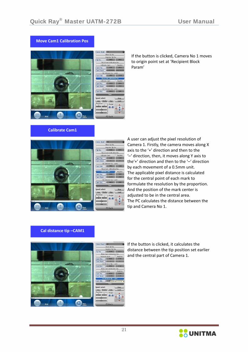
Move Cam1 Calibration Pos
Calibrate Cam1
Cal distance tip –CAM1
If the button is clicked, Camera No 1 moves to origin point set at ‘Recipient Block Param’
A user can adjust the pixel resolution of Camera 1. Firstly, the camera moves along X axis to the ‘+’ direction and then to the ‘–‘ direction, then, it moves along Y axis to the‘+’ direction and then to the ‘–‘ direction by each movement of a 0.5mm unit. The applicable pixel distance is calculated for the central point of each mark to formulate the resolution by the proportion. And the position of the mark center is adjusted to be in the central area. The PC calculates the distance between the tip and Camera No 1.
If the button is clicked, it calculates the distance between the tip position set earlier and the central part of Camera 1.

Quick Ray® Master UATM-272B User Manual
22
5.1.3 Marker Parameter
‘Marker Parameter’ is to set the variables for detecting marks on donor blocks and centers of recipient block holes. Those variables are consisting of ROI for detecting marks on donor blocks, model size, ROI and threshold for recognizing the recipient block hole. Please make sure of loading the TRAP file for the proper tip size to be met with the core size at Auto mode before setting ‘Marker Parameter’. If the button is clicked, the following screen appears.
Save
Donor ROI
After completing all the above steps, please make sure to save the new values to be applied to the program.
It shows an area of red‐lined square to search for marks on the donor block. The ROI area can be defined again. For example, when the area is defined, it reads the mark located on the left upper side from the four marks on the screen. When ‘ROI’ button is clicked, the red solid line turns into the dot‐line to change the area. After change of area, if the ‘ROI’ button is clicked again, the dot‐lined changes to the solid line and the changed area is saved.

Quick Ray® Master UATM-272B User Manual
23
ROI (Region of interest) is the region in the red square line in the following picture and a user can adjust the red line of current ROI to be positioned at the center of the two recipient block hole. If a user click ‘Recipient ROI’, the red square line will be changed to the red dotted line and if click ‘Recipient ROI’ again, the ROI can be adjusted by dragging the red line to change the ROI. After adjusting the ROI, please make sure of clicking ‘Recipient ROI’ again to save the value.
Search
Move
Recipient ROI
After selecting ‘White’ at ‘Select Donor Mark Color’, click ‘Search’ button to search white points (marks) on the tissue as shown in the following screen. The pre‐assigned threshold value can be modified by using the slide bar under the ‘Search’ button or ‘+ / ‐‘ button when needed. At this time, the reduced image is generated in the gray box under the ‘Donor Info’ and it helps to generate more accurate threshold value with an image. It is recommended that the suitable threshold value has to be set before starting the process. Otherwise, it may cause improper reading of the mark frequently.
If the button is clicked, cameras move to the desired positions of donor blocks and recipient block holes.

Quick Ray® Master UATM-272B User Manual
24
5.1.4 Recipient Hole Parameter ‘Recipient Hole Param’ button is clicked, the following screen will appear. A user can design the hole positions for iinseting tissues on the Recipient Block holes as you intended. Please make sure of loading the TRAP file of the proper tip size to be met with the core size at Auto mode before setting ‘Recipient Hole Parameter’.
You can select a specific block from the core sizes of 0.5mm, 1mm, 1.5mm, and 2mm at Combo box.
Select Model
Search
If click ‘Search’, CAMERA 2 can search the center of the recipient block hole as shown the below picture.

Quick Ray® Master UATM-272B User Manual
25
1) How to design of the recipient block holes (1) Please select one of 4 tools for one hole, holes in horizontal line, holes in vertical line, and
holes in retangle line. (2) Click ‘Include’ or ‘Exclude’ (3) Design the holes with the selected tool (4) Click 'Save' and check it.
.
After design of the recipient block holes, please make sure of click ‘Save’ to save the new design.
Select Area

Quick Ray® Master UATM-272B User Manual
26
6. OPERATION 6.1 Main menu You can choose one from 4 menus as below
6.1.1 Demo DEMO is to demonstrate the whole process of the work by simulating the process without the actual extraction and insertion of tissue samples for the purpose of enhancing user’s understanding of the instrument.
6.1.2 Auto Automated operation mode. Loading donor blocks and recipient blocks on the tray after inputting 3 parameters into ‘TARP’ file and execute ‘AUTO’. After the process, recipient blocks are loaded and the updated ‘TARP’ file is formulated. When the ‘AUTO’ is clicked, the screen changes as below.
DEMO AUTO
SET
EXIT
Display the captured picture (donor and recipient block)
Display status of the operation
Load log
Control command Icon
‘TARP’ file open
Display the current recipient block
Quick Ray® Master UATM-272B User Manual
27
6.1.3 Description of each Menu Menu Description
Auto To activate menus located at the right side of the screen for file loading, initializing or running, etc.
Manual To run the instrument manually when detection of marks on donor blocks or recipient block hole position is failed.
Main Menu To move to ‘Main’ menu
Load file To load the ‘TARP’ file containing data of donor block, core size, punch count, sample count and others
Initialize To perform the function of finding the original point of each axis motor.
Set Tray To move the main plate to the tray door for each donor block or recipient block to be replaced.
Select the Recipient Block
All: UATM‐272B is designed to load two recipient blocks simultaneously, and the tissues are inserted in the sequence of (A,1), (A,2), and (A,3) of recipient block A, and when insertion up to (N,N) is completed, it moves to insert at (A,1) of recipient block B. Make sure that two recipient blocks shall be of the same hole size. Copy: Tissues extracted from the same donor block can be inserted in the same Location on the other recipient block. For example, the sample 1 extracted from the first donor block 1 is inserted into the location (A,1) of the recipient block A, and the sample 2 collected from the first donor block 1 has to be inserted into the location (A,1) of recipient block B. At this time, the punch count must be the even number. Recip A: To insert the sample tissues into the holes of recipient block A only. If the recipient block A is completed with insertion, replace the recipient block A with new recipient block to continue. Recip B: To insert the sample tissues into the recipient block B only. If the recipient block B is completed with insertion, replace the block B with new recipient block to continue.
Start Start running. Pause To stop the current operation temporarily and ‘Start’ to restart the current work. Suspend When you want to continue your TMA works after finishing the current work
temporarily, if you click ‘ Suspend’ in the middle of your current work, the instrument will stop and the log file will be prepared and saved automatically. When a user wants to restart the program for a consecutive run, please click ‘Load Log’ button at the front screen. (For more detail, pls refer to 38 pages of this manual)
EMG Stop When encountered with any abnormal situation, click ‘EMG Stop’ to stop the program with music sound. Then, click ‘Complete’ button to return to the original point.’
6.1.4 SET To set up values for operation of the instrument. 6.1.5 EXIT To close the operation program and return to Window.

Quick Ray® Master UATM-272B User Manual
28
6.2 Installation of Puncher module A user can choose one tip module from 4 kinds of the tip modules suitable for the intended TMA work and install the selected tip module as the following steps.
1) Click ‘Auto’ to start
2) Click ‘Load File’ to call ‘TARP’ file already prepared for the intended tip size.
3) After loading ‘TARP’file, click ‘Main Menu’ and click ‘Set’

Quick Ray® Master UATM-272B User Manual
29
4) Click ‘Tip Body Param’
5) Click ‘Move’ at ‘Change Tip Position’ Then, the tip module and the tray move to the center for a user to install a tip module.
6) A user can select a tip size matching with the tip size in ‘TARP’ file and install the selected tip as a following way.
7) After installing the tip module, please follow the below steps for your work.
DO NOT CARE
a. Turn the tip counterclockwise to uninstall. b. Turn the tip clockwise to install

Quick Ray® Master UATM-272B User Manual
30
6.3 Preparation before running instrument
(1) Loading the recipient blocks into the recipient block holder.
① Put a recipient block (a) into the recipient block holder top (b)
② Inserting the recipient block top with recipient block into the groove of recipient block holder body (c) and push it to the end.
③ Spin the adjust screw (d) to the lock direction to tighten up the recipient block (a) to recipient block holder top (b) to the end.
④ The fitted recipient block holder.
⑤ Mounting the recipient block holder onto the recipient block tray
<Recipient Block Tray> <Recipient Block Holder>
Mount the recipient block holder onto the recipient block tray by inserting the holder with the groove side facing at the A or B mark on the tray. (2) Loading the pre‐marked donor block into the donor block tray. Donor blocks are to be loaded into the donor block tray after marking with oil ink on tissues to be extracted. Please make sure that the marked ink should be dried up completely.
• Keep a safe distance between your head or face and the front door of the instrument.• Be careful about your fingers or hand not to be scratched by the needle of tip when assembling or disassembling the puncher or block trays or main plate or when cleaning the interior of the instrument or the tip.
• Be careful not to pinch your fingers when closing the front door of the instrument.

Quick Ray® Master UATM-272B User Manual
31
<Donor Block Tray>
(3) Loading the tray into the main tray. Load the donor block tray and the recipient block holder tray into the main plate.
(4) Procedure of loading the block tray into the main plate of the instrument.
① Turn on the instrument.
② Start ‘AUTO’ mode.
③ Load ‘TARP’ file and click ‘Set Tray’ button
④ Open the tray door.
⑤ Load the donor block tray and the recipient block holder tray into the main plate of the instrument.
⑥ Close the tray door. (5) Removing the recipient blocks from the instrument
① Wait until the operation of the instrument is completed or stopped. You can hear the music from the instrument when the operation is completed.
② Open the tray door.
③ Unload the recipient block holder tray from the main plate of the instrument.
④ Unload the recipient block holder from the recipient block holder tray.
⑤ Unload recipient blocks from the recipient block holder.
⑥ After unloading recipient blocks, replace the empty recipient block holder into the main plate.
⑦ Close the tray door.

Quick Ray® Master UATM-272B User Manual
32
6.4 Start to run (UATM.EXE) ① Please check the USB 2.0 and the PC connected and also check the Emergency switch released
② First, Turn on the main S/W located in the right side of the instrument.
③ Then, Turn on the PC after 10 seconds and wait until Window booted completely.
④ Excute ‘UATM.exe’ to operate the instrument.
Click the above icon, then the following main screen appears, and 4 axes of X, Y, Z, and P move to the original point automatically.
6.4.1 Click ‘AUTO’ menu Click the ‘AUTO’ button on the screen, then, the screen changes as below.
When a user click ‘UATM.exe’ to start running, the instrument will initialize automatically. But, if a user wants to initialize the instrument additionally, please click this button.
Load file
Quick Ray® Master UATM-272B User Manual
33
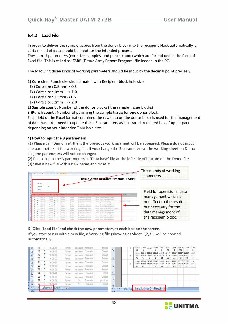
6.4.2 Load File In order to deliver the sample tissues from the donor block into the recipient block automatically, a certain kind of data should be input for the intended process. These are 3 parameters (core size, samples, and punch count) which are formulated in the form of Excel file. This is called as ’TARP’(Tissue Array Report Program) file loaded in the PC. The following three kinds of working parameters should be input by the decimal point precisely. 1) Core size : Punch size should match with Recipient block hole size. Ex) Core size : 0.5mm ‐> 0.5 Ex) Core size : 1mm ‐> 1.0 Ex) Core size : 1.5mm ‐>1.5 Ex) Core size : 2mm ‐> 2.0 2) Sample count : Number of the donor blocks ( the sample tissue blocks) 3 )Punch count : Number of punching the sample tissue for one donor block Each field of the Excel format contained the raw data on the donor block is used for the management of data base. You need to update these 3 parameters as illustrated in the red box of upper part depending on your intended TMA hole size. 4) How to input the 3 parameters (1) Please call 'Demo file', then, the previous working sheet will be appeared. Please do not input the parameters at the working file. If you change the 3 parameters at the working sheet on Demo file, the parameters will not be changed. (2) Please input the 3 parameters at 'Data base' file at the left side of bottom on the Demo file. (3) Save a new file with a new name and close it.
5) Click ‘Load file’ and check the new parameters at each box on the screen. If you start to run with a new file, a Working file (showing as Sheet 1,2,3..) will be created automatically.
Three kinds of working parameters
Field for operational data management which is not affect to the result but necessary for the data management of the recipient block.

Quick Ray® Master UATM-272B User Manual
34
6.4.3 Select Recipient Block
You can select the number of recipient block. If you select ‘All’, you can insert the sample tissues into the recipient block A and B in order. If you select ‘RecipA’
or ‘RecipB’, you can insert the sample tissues into the selected recipient block respectively. And if you select ‘Copy’, you can insert the sample tissues extracted from the same donor block into the recipient block A and B one by one which means you can make an additional recipient block B+. ‘All’ is initially activated as default mode. 6.4.4 Set Tray
If the button is clicked, the main plate moves to the tray door. Then, open the front door and load the prepared donor block tray and the
prepared recipient block holder tray on the main plate as followed by the article 6.3
<Loading the donor block tray and the recipient block holder tray> 6.4.5 Start TMA work After completing all the above steps, click the ‘START’ button to operate by the following sequence.
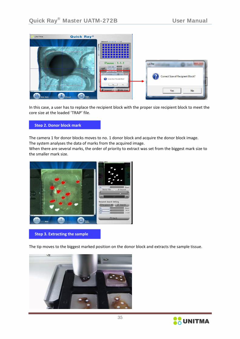
As the recipient block has the symmetrical frame in every direction, a direction marking on a certain place of recipient block will be helpful for you to manage the data by recognizing the direction of block. In case that if the core size input at the loaded ‘TARP’ file will not be met with the actual core size on the recipient block tray, the following message will be shown.
Step 1. Direction mark on recipient
Quick Ray® Master UATM-272B User Manual
35
In this case, a user has to replace the recipient block with the proper size recipient block to meet the core size at the loaded ‘TRAP’ file. The camera 1 for donor blocks moves to no. 1 donor block and acquire the donor block image. The system analyses the data of marks from the acquired image. When there are several marks, the order of priority to extract was set from the biggest mark size to the smaller mark size.
The tip moves to the biggest marked position on the donor block and extracts the sample tissue.
Step 2. Donor block mark
Step 3. Extracting the sample

Quick Ray® Master UATM-272B User Manual
36
The camera 2 for recipient block searches the center of corresponding hole and calculates to compensate the coordinates value of the hole before inserting.
The instrument inserts the extracted tissue into the detected recipient block hole.
The instrument continues to work until the intended work will be completed and finish the work with displaying a pop‐up with music as below in case of the sample count under 10.
Step 4. Detecting Recipient Block
Step 5. Inserting the sample tissue
Step 6. Finish

Quick Ray® Master UATM-272B User Manual
37
1) Replacement of the blocks During the operation, when donor blocks or recipient blocks are consumed completely, the message of ‘Please replace donor (or recipient) blocks’ pops up. At the same time, the main plate moves to the tray door for a user to replace the current blocks with new ones. After the block replacement, click the ‘Complete’ button on the window and click the ‘Continue’ button in the screen to continue the work.
2) A completed receipient block and Data
After completion of the work, you get two outputs. As illustrated below, one is the completed recipient block and the other is ‘TARP’ report containing ID of the sample tissues inserted into recipient block holes.
Step 7. ‘TARP’ file confirm

Quick Ray® Master UATM-272B User Manual
38
6.4.6 Stop TMA Work & Consecutive work 1) Pause To stop the current operation temporarily and ‘Start’ to restart the current work. 2) Suspend If you want to continue your TMA works after finishing the current work temporarily, you need to follow the below steps. (1) Input the total sample number in ‘Sample’ at TARP in Article 6.4.2. in order to continue the total TMA work with only a existing programmed TARP file. If you input the 3 parameters in TARP file, it means a new file is created. So, if you want to continue your whole TMA work with only a file, you need to create one TRAP file with input the total sample number for a project. In case you input the total sample number in TARP file and you need to complete the whole work before completing the work up to the total input samples, if you click ‘Load Log’ and click ‘New file’ then the log file is completed at once and the existing log file converts to a completed file and saved automatically. (2) Click ‘Suspend’ button in the middle of your current work if you want to stop your current work temporarily. Please note if you complete the current work without click ‘Suspend’, or if you click ‘Suspend’ after completing the currently programmed work and restart the instrument, you cannot use the existing file, but only a new file is created. Please make sure you should click ‘Suspend’ in the middle of your current work, then the current run will stop at once after completing only the current step. (3)Then, the instrument is stopped and the log file will be created and saved automatically. When a user wants to restart the program for a consecutive run, please click ‘Load Log’ button at the front screen, then, the following message will be shown.
Donor block ID record in the corresponding hole of the recipient block.

Quick Ray® Master UATM-272B User Manual
39
① In case of click ‘Existing file load’, the POP is disappeared, and please click’ Start’ to do the consecutive work. The work will be started from a new hole next to the previous filled hole on the recipient block.
② On the other hand, when selecting ‘New file load’, the warning sign shows that ‘New TMA work will be started (the suspended work is to be finished by saving the existing work data)’. Please Click ‘OK’ , then new window is opened. You can load a prepared file in order to do your intended TMA work and start a new TMA work.
③ If there are no options that a user intends, pls click ‘Cancel’ button, then, the pop up menu will be closed and go back to the suspended mode. 3) EMG Stop When encountered with any abnormal situation, click ‘EMG Stop’ to stop the program with a music sound. Then, click ‘Complete’ button to return to the original point.

Quick Ray® Master UATM-272B User Manual
40
6.4.7 Teaching mode In the following cases, the message of ‘Do you want Donor Block teaching mode?’ is appeared on the screen. 1) When the camera failed in detecting the mark on a donor block or there are no marks on the donor block.
When the message ‘Do you want Donor Block teaching mode?’ is appeared as shown the above screen, after click ‘Yes’, a user can designate the desired area of the donor block on the screen by a finger or a mouse, then, press ‘Donor set’ under ‘Mark & Hole Position Setting’ on the right screen. And then, the Puncher tip pick up the sample on the designated area on the donor block and insert the sample into the correspondent hole of the recipient block.
In case of clicking ‘No’, the puncher will not pick up the sample on the current donor block and continue to pick up the sample from the next donor block. Then, the color of the current empty hole of the recipient block turns Blue color as shown on the above screen. We do not recommend a user to press ‘No’ when the message of ‘Donor Block teaching mode?’ on the screen. All the users make sure of marking the position to be extracted from the donor blocks properly and load the marked donor blocks onto the tray after the marked oil ink is dried completely. 2) When the recipient block hole was blocked as shown the below screen.

Quick Ray® Master UATM-272B User Manual
41
When the message of ‘Do you want Recipient Block teaching mode?’ is appeared as shown on the above screen,Please press ‘Yes’ and designate the hole of the recipient block, and then, press ‘Recipient set’ under ‘Mark & Hole Position Setting’ on the right side of the screen. Then, the Puncher tip will insert the extracted sample into the designated hole of the current receipient block.
In
In case of clicking ‘No’, the pucher will not insert the sample into the current hole of the recipient block, and continue to insert the extracted sample into the next hole of the recipient block. In this case, the color of the current empty hole of the recipient block will turn to Red color. Recipient Block. We do not recommend a user to press ‘No’ when the message of ‘Donor Block teaching mode?’on the screen. In order to avoid this case, all the users make sure of checking the recipient block holes to see if any holes are blocked.
In order to avoid the work at ‘Teaching mode’ during the work at ‘Auto mode’, we recommend the users to follow the belows;
1) All the users make sure of marking the position to be extracted from the donor blocks properly and load the marked donor blocks onto the tray after the marked oil ink is dried completely.
2) All the users make sure of checking the recipient block holes to see if any holes are blocked.
In case of separation of the Donor Block from a plastic cassette during operation
When the donor block is separated from the plastic cassette and is failed in detecting the marked position on the donor block by camera, the following message will be shown as ‘Please check the donor block’ and the instrument will stop. In this case, a user need to check the situation by the naked eyes through the front door, and clear the seperated donor block and the casstte from the tray by opening the front door, and click ‘OK’ to do work from the next donor block.

Quick Ray® Master UATM-272B User Manual
42
6.5 Manual mode If the ‘Manual’ button is clicked, the screen changes as below. User can operate the instrument step by step manually as operated by ‘Auto’ mode. In this case, a user should input the information of donor block to be worked manually into the correspondent column at the ‘TARP’ file again. ‘Manual’ mode is configured with the total of 2 pages; Manual page 1 is used to control the motion related to the donor block and Manual page 2 is used to control the motion related to the recipient block. It is useful in the event that the instrument fails in detecting marks on the donor blocks or in extracting sample tissues from the donor blocks during ‘Auto’ mode. However, when a unskilled person manipulate this ‘Manual’ mode, it may cause damage to the instrument due to mechanical collision, so you should be careful with this step. 1) Step at the Manual page 1
Menu Description of function Set To save its value after selection of ‘Core Size’. Each core size of recipient blocks
should be matched with the size of tip. Cam Move To move the camera to focus on the selected donor block at the Manual page 1. Mark Search
To detect the mark in the selected ‘ROI (Region Of Interest)’. Marks detected by the size sequence are revised by the value of Pos.x and Pos.y. In addition, you can define the position of sample tissues to be extracted by using the mouse.(Manual page 1)
Tip Move If the values of Pos.x and Pos.y are within the ‘ROI’ area, the tip can be moved to the position of the value. When the position value is deviated from the ‘ROI’, an error message shows that the tip cannot reach the position. This is to prevent the tip from the possible damage which may occur in the event that the improper location is input. In this case, click ‘Cam Move’ button again, then it will search the mark again.(Manual page 1)
Tip Down The tip is coming down to the cassette surface level to extract the sample tissue from the donor block. You should be careful enough to check the tip position before clicking the button to prevent the tip from the possible damages. (Manual page 1)
Tip Up To lift the tip from the surface of cassette to perform next procedure (Manual page 1)
Manual page1 Enter ‘Core Size’ and click ‘Set’ Enter ‘Donor block’ Click ‘Cam Move’ Click ‘Mark Search’ Click ‘Tip move’ click ‘Tip Down’
click ‘Tip Up’ (tissue extracted) The above is for Manual page 1 and click ‘Next ►►’ at Select Area’ to proceed to Manual page2

Quick Ray® Master UATM-272B User Manual
43
Menu Description of function Prev To move to the Manual page 1 for Recipient block from Manual page 2.
(The button is inactivated at Manual page 1) Next To move to the Manual page 2 for Recipient block.
(The button is inactivated at Manual page 2) Motion Controller
The above picture shows the motion controller. You can use ‘Speed select’ to adjust the speed fixed at the ‘Set’ mode. ‘Position’ displays the position of each axis. The ‘Plunger’ controls the tip needle. The ‘RED ARROW’ buttons are to control X and Y axis, and ‘BLUE ARROW’ buttons inside of ‘RED ARROW’ buttons control Z axis for Cam 1, Cam 2 and the tip.‘Stop’ button is to suspend motions not intended.
2) Step at the Manual page 2
Menu Description of function Set To save its value after selection of ‘Core Size’. Each core size of recipient blocks
should be matched with the size of tip. Cam Move To move the camera to the selected hole position of the recipient block at the
Manual page 2. then all process is completed, press this button again to confirm the condition of the current work on Manual page 2.
Mark Search
To find the center of the hole registered at the ‘Marker Param’in advance. In addition, you can define the position of the recipient block hole for the extracted tissue to be inserted by using the mouse. (Manual page 2)
Tip Move The tip comes down to the surface of the selected recipient block hole. Be careful of the tip position to prevent the tip from the possible damages. (Manual page 2)
Tip Down The tip moves to the surface of the selected hole on the recipient block. To prevent the tip from the possible damages, be careful enough to check the tip position before clicking the button. (Manual page 2)
Push Recipient block hole insert.
Manual page2 Enter Recipient block no. Enter Row no. Enter Column no. Click‘Cam move’ click ‘Mark Search’ click ‘Tip move’ click ‘Tip Down’ click ‘Push’(insertion) Click‘Tip Up’ The above is for Manual page2 and click ‘◄◄Prev’ to proceed to Manual page1 for continuance.

Quick Ray® Master UATM-272B User Manual
44
Menu Description of function Tip Up To lift the tip from the surface of recipient block to perform next procedure.
(Manual page 2) Prev To move to the Manual page 1 for Recipient block from Manual page 2.
(The button is inactivated at Manual page 1) Next To move to the Manual page 2 for Recipient block.
(The button is inactivated at Manual page 2) Motion Controller
The above picture shows the motion controller. You can use ‘Speed select’ to adjust the speed fixed at the ‘Set’ mode. ‘Position’ displays the position of each axis. The ‘Plunger’ controls the tip needle. The ‘RED ARROW’ buttons are to control X and Y axis, and ‘BLUE ARROW’ buttons inside of ‘RED ARROW’ buttons control Z axis for Cam 1, Cam 2 and the tip.‘Stop’ button is to suspend motions not intended.

Quick Ray® Master UATM-272B User Manual
45
7. TROUBLE SHOOTING
Step Symptom Cause Measures Installation Connection fail ‘Servo connect fail’
is appeared when click ‘UATM.EXE’ to start
1) Please check if instrument is connected to USB 2.0 port at the PC .
2) Please check if EMG button is released, otherwise, turn the EMG S/W to the right to release.
3) Turn off the current OS and PC power switch.
4)Turn off the power switch of Instrument.
5) Turn on the power switch and turn on the PC switch in order.
6) Start ‘UATM.exe’ again. Proper parameters were not input at ‘TARP’ file
Parameters with wrong value were entered or operation with improper routine
Terminate the program and run ‘UATM.exe’ again to input the proper parameters at ‘TARP’ file
In case of the broken tip
• tip may be broken when it pick up the hard tissue like a bone tissue. • a tip was broken by dropping or hit by other objects.
A user shoud replace the tip with new one.
AUTO Failure of detecting the mark on Donor block
‘ROI’of donor block was not set properly.
Set ‘ROI’ of donor block properly
Improper value of Threshold
Readjust ‘Threshold value’
Failure of detecting the mark on Donor block
Wrong setting with donor mark color
Set donor mark color properly
No marks on the donor block
Use ‘Teaching mode’ to designate a position on a donor block to be pick up
Failure of Recipient block hole detection
Wrong setting ‘Model Size’
Set the suitable ‘Model Size’
Wrong setting with ‘ROI’
Set ‘ROI’ properly
Improper value of Threshold
Readjust ‘Threshold value’
Faulty condition of recipient block hole
Run ‘Teaching mode’ or use proper recipient blocks
Recipient hole is out of range from camera FOV (field of view).
Adjust block position at ‘Recipient Block Param’

Quick Ray® Master UATM-272B User Manual
46
Step Symptom Cause Measures Auto Sample tissue
is not extracted completely
Puncher tip does not reaches down to donor block cassette surface completely
Adjust value of sampling Z at ‘Tip body Param’
Tissue contains foreign substance
Do not use donor block with foreign substance
Failure of tissue insertion
Tissue sticks to the tip because marking ink is not dried up
Use donor block after marking ink dries up completely
Teaching Mode
No mark on a donor block
No marking, an improper mark, a dim mark, an erased mark
1) Stop running and mark on the blocks and start again
2) Designate a position on the donor block with a mouse or a finger on the monitor at ‘Teaching mode’ and click ‘Donor set’ to continue
Failure of recognizing by a camera even if the tip extracted the sample tissue from a donor block
The color of plastic cassette is too bright for camera to distinguish the color of the donor block buttom and the color of mark.
1) In this case, the puncher will try to extract the sample twice more automatically, then, the pop up with message ‘Retry’ or ‘Next’, then click ‘Next’ to continue the work by checking if the puncher extract the sample
2) Plastic cassette with heavy yellow color is recommended for camera to distinguish the color of donor block buttom and the color of mark on the donor block
Camera fails in recognizing the actually extracted sample
The camera fails in distinguishing the colors between the plastic cassette color and the marked ink color since the plastic color is very similar with the ink color marked on the donor block .
1) In this case, the puncher try to pick up the sample twice more.
2) When ‘Retry’ or’Next’ is appeared, click ‘Next’ to continue the next work automatically.
3) A use is recommended to use the donor block cassette with a heavy yellow color.
Separation of the paraffin block from plastic cassette during extracting the sample tissue
The very old paraffin block or the very hard paraffin block are easy to be separated.
1) stop running at ‘Auto’ mode and try to pick up the sample at ‘Manual’ mode after installing the suitable donor block into the tray
2) Recommended not to use a very old and hard paraffin blocks to avoid the separation of the paraffin blocks from the plastic cassette.

Quick Ray® Master UATM-272B User Manual
47
8. CLEANING & MAINTENANCE
8.1 Cleaning the instrument
• Cleaning the connectors Do not use when the connecting cables of the instrument and AC power cord are not clean. Remove the dirt with a dry cloth or cotton swab. When being used under unclean condition, the flow of electrical current may be obstructed.
• Cleaning the exterior surface Wipe gently with a damp cloth and dry the surface. Do not use solvents or other chemicals to clean the exterior of the instrument. Clean he ventilation grids on the side of housing panels with a brush or vacuum cleaner to remove dust and dirt.
• Cleaning the interior surface Open the cover door and wipe gently with a damp cloth and then dry the surface. Do not use solvents or other chemicals to clean the interior of the instrument.
• Cleaning the block holder tray 1) Unplug the AC power cord from the electrical outlet. 2) Open the tray door. 3) Disassemble the block holder frame from the instrument. 4) Disassemble the donor block holder top and recipient block holder from the block holder tray. 5) Wipe the recipient block holder top and the recipient block holder bottom and the block holder frame gently with a damp cloth, and then dry the surface. Do not use solvents or other chemicals to clean the interior of the instrument.
8.2 Consumables Four different sizes of Recipient block to be supplied by the manufacturer :
• For safety reasons, unplug the AC power cord from the electrical outlet before cleaning.
• Do not allow liquid or small particles to get into the instrument or accessories when cleaning.
16 x 20 (320 holes with 0.5 mm in diameter) 10 x 12 (120 holes with 1.0 mm in diameter) 9 x 10 (90 holes with 1.5 mm in diameter) 6 x 10 (60 holes with 2.0 mm in diameter)
<0.5mm> <1.0mm> <1.5mm> <2.0mm>

Quick Ray® Master UATM-272B User Manual
48
8.3 Maintenance 8.3.1 Checking the instrument UNITMA recommends that the instrument be checked by a user at least every six months or whenever you move the location of the instrument.
Check Action
Exterior & Interior Clean as per the instruction (see 8.1 Cleaning the instrument)
Labels Check for readability or missing labels.
AC cord Check the cord and molded connectors for damage.
Feet Check for presence of all four feet.
Check feet for physical damages or deterioration.
Power cord receptable Make sure receptable is free of foreign matter
Check for presence of all 3 connector pins and make sure they are
straight.
8.4 Repair
9. WARRANTY & SERVICE UNITMA Co., Ltd. offers the limited warranty for the Quick Ray Master against defects in material and workmanship under normal use and service for period of 1 year from the date of purchase.
9.1 Terms & Conditions 1) UNITMA will, at no charge, either repair the Quick Ray Master (with new parts) or replace it with a new unit during the warranty period provided it is returned in accordance with the term of the warranty. Replaced new parts are warranted for the balance of the original applicable warranty period. Replaced defect parts of the product shall become the property of UNITMA.
2) This limited warranty is provided by UNITMA to the original end‐user purchaser and is not assignable or transferable to any other third party.
3) UNITMA cannot be responsible in any way for any additional equipment not furnished by UNITMA which has been attached to or used in connection with the product.
4) Customer must provide a proof of purchase (bearing the date of purchase and the product’s serial number) in order to receive the warranty service. Warranty service will be provided by UNITMA through one of its authorized warranty service centers.
• Contact UNITMA for repair services, replacement of components, and additional consumables.

Quick Ray® Master UATM-272B User Manual
49
9.2 The Warranty does not cover : 1) Defects or damage resulting from the use of the product other than its normal customary usage. 2) Defects or damage from misusage such as breakage, spillage or liquid or substances that can cause circuit‐shortcut of the electronic boards and battery leakage, etc.
3) Defects or damage from improper testing, operation, installation, alteration, modification or adjustment of the instrument.
4) Breakage or damage unless caused directly by the defects in material and workmanship. 5) A product with unauthorized modification, dissembling, and/or repair which adversely affect the performance.
6) A product with serial number and/or the warranty seal removed or made ineligible. 7) Scratches or other cosmetic damage to the product that do not affect the operation. 8) Normal and customary wear and tear. 9) Force Majeure : any damage beyond the reasonable control of UNITMA such as but not limited to : Fire, Flood, Earthquake, act of Terrorism, etc.
10) Shipping costs for pick‐up and delivery from user’s facility.
9.3 Contact for technical service UNITMA Co., Ltd. 102, Saehan B/D, 5, Bokjeong‐ro, Sujeong‐gu, Seongnam‐si, Gyeonggi‐do, 13119, Korea Tel : +82 31 721 8003 / +82 2 420 0070 Fax: +82 31 751 8003 e‐mail : [email protected] website : http://www.unitma.com