Automated Lattice Optimization of Hinge Fitting with ... · PDF fileAUTOMATED LATTICE...
16
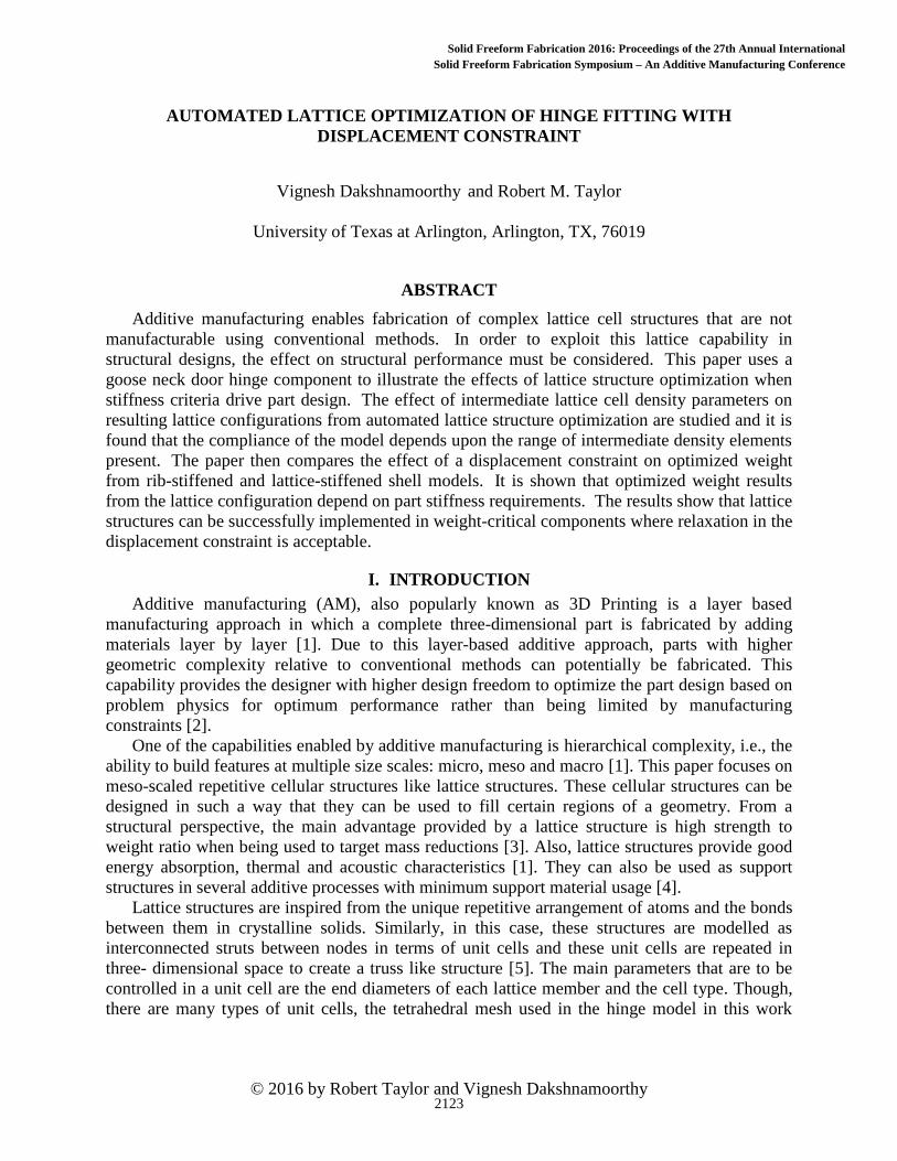
© 2016 by Robert Taylor and Vignesh Dakshnamoorthy AUTOMATED LATTICE OPTIMIZATION OF HINGE FITTING WITH DISPLACEMENT CONSTRAINT Vignesh Dakshnamoorthy and Robert M. Taylor University of Texas at Arlington, Arlington, TX, 76019 ABSTRACT Additive manufacturing enables fabrication of complex lattice cell structures that are not manufacturable using conventional methods. In order to exploit this lattice capability in structural designs, the effect on structural performance must be considered. This paper uses a goose neck door hinge component to illustrate the effects of lattice structure optimization when stiffness criteria drive part design. The effect of intermediate lattice cell density parameters on resulting lattice configurations from automated lattice structure optimization are studied and it is found that the compliance of the model depends upon the range of intermediate density elements present. The paper then compares the effect of a displacement constraint on optimized weight from rib-stiffened and lattice-stiffened shell models. It is shown that optimized weight results from the lattice configuration depend on part stiffness requirements. The results show that lattice structures can be successfully implemented in weight-critical components where relaxation in the displacement constraint is acceptable. I. INTRODUCTION Additive manufacturing (AM), also popularly known as 3D Printing is a layer based manufacturing approach in which a complete three-dimensional part is fabricated by adding materials layer by layer [1]. Due to this layer-based additive approach, parts with higher geometric complexity relative to conventional methods can potentially be fabricated. This capability provides the designer with higher design freedom to optimize the part design based on problem physics for optimum performance rather than being limited by manufacturing constraints [2]. One of the capabilities enabled by additive manufacturing is hierarchical complexity, i.e., the ability to build features at multiple size scales: micro, meso and macro [1]. This paper focuses on meso-scaled repetitive cellular structures like lattice structures. These cellular structures can be designed in such a way that they can be used to fill certain regions of a geometry. From a structural perspective, the main advantage provided by a lattice structure is high strength to weight ratio when being used to target mass reductions [3]. Also, lattice structures provide good energy absorption, thermal and acoustic characteristics [1]. They can also be used as support structures in several additive processes with minimum support material usage [4]. Lattice structures are inspired from the unique repetitive arrangement of atoms and the bonds between them in crystalline solids. Similarly, in this case, these structures are modelled as interconnected struts between nodes in terms of unit cells and these unit cells are repeated in three- dimensional space to create a truss like structure [5]. The main parameters that are to be controlled in a unit cell are the end diameters of each lattice member and the cell type. Though, there are many types of unit cells, the tetrahedral mesh used in the hinge model in this work 2123 Solid Freeform Fabrication Symposium – An Additive Manufacturing Conference Solid Freeform Fabrication 2016: Proceedings of the 27th Annual International
-
Upload
truongkien -
Category
Documents
-
view
224 -
download
4
Transcript of Automated Lattice Optimization of Hinge Fitting with ... · PDF fileAUTOMATED LATTICE...
© 2016 by Robert Taylor and Vignesh Dakshnamoorthy
1
AUTOMATED LATTICE OPTIMIZATION OF HINGE FITTING WITH
DISPLACEMENT CONSTRAINT
Vignesh Dakshnamoorthy and Robert M. Taylor
University of Texas at Arlington, Arlington, TX, 76019
ABSTRACT
Additive manufacturing enables fabrication of complex lattice cell structures that are not
manufacturable using conventional methods. In order to exploit this lattice capability in
structural designs, the effect on structural performance must be considered. This paper uses a
goose neck door hinge component to illustrate the effects of lattice structure optimization when
stiffness criteria drive part design. The effect of intermediate lattice cell density parameters on
resulting lattice configurations from automated lattice structure optimization are studied and it is
found that the compliance of the model depends upon the range of intermediate density elements
present. The paper then compares the effect of a displacement constraint on optimized weight
from rib-stiffened and lattice-stiffened shell models. It is shown that optimized weight results
from the lattice configuration depend on part stiffness requirements. The results show that lattice
structures can be successfully implemented in weight-critical components where relaxation in the
displacement constraint is acceptable.
I. INTRODUCTION
Additive manufacturing (AM), also popularly known as 3D Printing is a layer based
manufacturing approach in which a complete three-dimensional part is fabricated by adding
materials layer by layer [1]. Due to this layer-based additive approach, parts with higher
geometric complexity relative to conventional methods can potentially be fabricated. This
capability provides the designer with higher design freedom to optimize the part design based on
problem physics for optimum performance rather than being limited by manufacturing
constraints [2].
One of the capabilities enabled by additive manufacturing is hierarchical complexity, i.e., the
ability to build features at multiple size scales: micro, meso and macro [1]. This paper focuses on
meso-scaled repetitive cellular structures like lattice structures. These cellular structures can be
designed in such a way that they can be used to fill certain regions of a geometry. From a
structural perspective, the main advantage provided by a lattice structure is high strength to
weight ratio when being used to target mass reductions [3]. Also, lattice structures provide good
energy absorption, thermal and acoustic characteristics [1]. They can also be used as support
structures in several additive processes with minimum support material usage [4].
Lattice structures are inspired from the unique repetitive arrangement of atoms and the bonds
between them in crystalline solids. Similarly, in this case, these structures are modelled as
interconnected struts between nodes in terms of unit cells and these unit cells are repeated in
three- dimensional space to create a truss like structure [5]. The main parameters that are to be
controlled in a unit cell are the end diameters of each lattice member and the cell type. Though,
there are many types of unit cells, the tetrahedral mesh used in the hinge model in this work
2123
Solid Freeform Fabrication 2016: Proceedings of the 26th Annual InternationalSolid Freeform Fabrication Symposium – An Additive Manufacturing Conference
Solid Freeform Fabrication 2016: Proceedings of the 27th Annual International

© 2016 by Robert Taylor and Vignesh Dakshnamoorthy
2
generates lattice beam elements on the edges of relevant tetrahedral intermediate density
elements to form unit cells..
This work uses a goose neck door hinge component to illustrate the effects of lattice structure
optimization when stiffness criteria drive part design. The lattice optimization is executed using
an approach driven by a topology optimization algorithm. During topology optimization, the
density of elements are discretized as either 0 (void) or 1 (solid). Whereas, when a lattice
optimization is performed, the intermediate density elements are converted into lattice structures.
Due to the porous nature of these cellular structures, compliance of the model tends to increase
upon their inclusions. The first half of the paper illustrates the effect of intermediate cell density
settings on compliance of the model and the second half of the paper compares the effect of a
displacement constraint on the mass of rib stiffened and lattice stiffened models.
II. BACKGROUND
Previous work performed in the fields of lattice structures, topology optimization, lattice
optimization, and the effects of lattice optimization on part stiffness is discussed in this section.
A. LATTICE STRUCTURES
Due to advancements in AM, there has been a considerable increase in research in the area of
cellular structures and especially lattice structures. A significant amount of work has been done
to investigate the applications and properties of lattice cells. Stucker, et al. [6], has shown that
periodic lattice filters can be used efficiently in casting of molten metals as a replacement to
ceramic foam filters. Additionally, due to its excellent thermal properties, heat exchangers are
modeled after a tetrahedron diamond lattice design by Heidrich et al. [7] and in the field of metal
AM, lattice cells are widely used as support structures leading to minimal support material usage
(Hussein et al.) [8].
Extensive research has also been done on lattice cell parameters and properties. Most
commonly, strut thickness is considered as a key design variable in a lattice unit cell. Whereas,
the work by Tang et al. [5] shows that the orientation of lattice cells plays an important role on
structural properties. Iyibilgin et al. [9] observed that lattice structures built using fused
deposition modeling process has higher strength compared to specimens with same porosity built
using the sparse and sparse-double dense styles. Another work by Maskery et al. [10]
demonstrates through experimental testing that the mechanical properties of latticed parts are a
function of unit cell size. In cellular structures, the octet truss lattice configuration is a widely
studied cell structure. Deshpande et al. [11] have analyzed the mechanical properties of an octet
unit cell by considering it as struts that are pin jointed at its vertices and have found good
agreement in results between analytical predictions and FE calculations.
B. TOPOLOGY OPTIMIZATION
A topology optimization problem is formulated such that optimal spatial distribution of
material is obtained for a given set of loads and boundary conditions to minimize or maximize a
certain objective function [12]. Topology optimization is performed to obtain a concept design
that usually requires further fine tuning by shape and sizing optimizations. Several optimization
algorithms are developed for this purpose. Initially in 1988, a homogenization method based on
square and rectangular holes was introduced by Bendsoe and Kikuchi [13] and it was further
developed into the SIMP method (Solid Isotropic Microstructure with Penalization) by Rozvany,
who has performed a detailed evaluation of available topology optimization algorithms in his
work [14].
2124
© 2016 by Robert Taylor and Vignesh Dakshnamoorthy
3
C. LATTICE OPTIMIZATION
Lattice optimization has been implemented as an extension of topology optimization. The
main task involved in lattice optimization is to develop an algorithm for designing lattice
structures. Several methods have been proposed for designing these cellular structures. For
instance, Nguyen et al. [15] proposed a two-step approach for designing conformal lattice
structures (CLS) based on a heuristic which assumes, stress distributions are similar in CLS and
in a solid body of same shape. As an alternative to the time consuming traditional CAD software,
McMillan et al. [4] have developed a programmatic method for generating lattice structures
directly in the STL format and in order to deal with computational and storage complexities in
CAD systems caused by large conformal truss structures, a hybrid modeling method was
developed by Wang et al. [16]. Further, a size matching and scaling method was developed by
Chang et al.[17] for designing meso-scaled lattice structures. Hao et al. [18] have established an
image based algorithm for developing periodic lattice structures and have investigated its
manufacturability using selective laser melting (SLM) process. A comparison was done between
uniform voxel based approach and conformal lattice approach for constructing lattice structures
by Park et al.[19]. Finally, another comparative study was done between Particle Swarm
Optimization (PSO) and least-squares minimization (LSM) for designing cellular structures by
Chu et al. [20]. Later, it was found that PSO was more effective in searching large design spaces
whereas LSM converged more quickly than PSO.
This work uses the Altair OptiStruct Optimization program [21] for lattice optimization.
Specifically, the work uses OptiStruct version 13, which is the initial lattice optimization release
and has certain capability limitations. Some of the current limitations of the program include:
lattice strut mesh dependency, lattice structures limited to circular cross section, and an inability
to remove lattice members below a threshold diameter limit.
D. EFFECT OF LATTICE OPTIMIZATION ON PART STIFFNESS
This work illustrates the dependence of structural compliance on the extent of lattice
structures present in a part. Similarly, Rosen et al. [22] has demonstrated that stiffness of octet-
truss structure decreases with an increase in the number of cells and Cerardi et al. [23] observed
the inverse relationship between mechanical properties (stiffness and tensile strength) and the
porosity rate (lattice cells) in three different structures. These results are in agreement with an
investigation performed by Sudarmadji et al. [24] who demonstrated the inverse relationship
between stiffness and porosity in functionally graded scaffolds using 13 different polyhedral
configurations.
III. LATTICE STRUCTURE DESIGN OPTIMIZATION
This section provides the model details and its topology and lattice optimization results.
Further, the effects of intermediate density range and porosity parameter value are discussed.
A. HINGE MODEL DETAILS
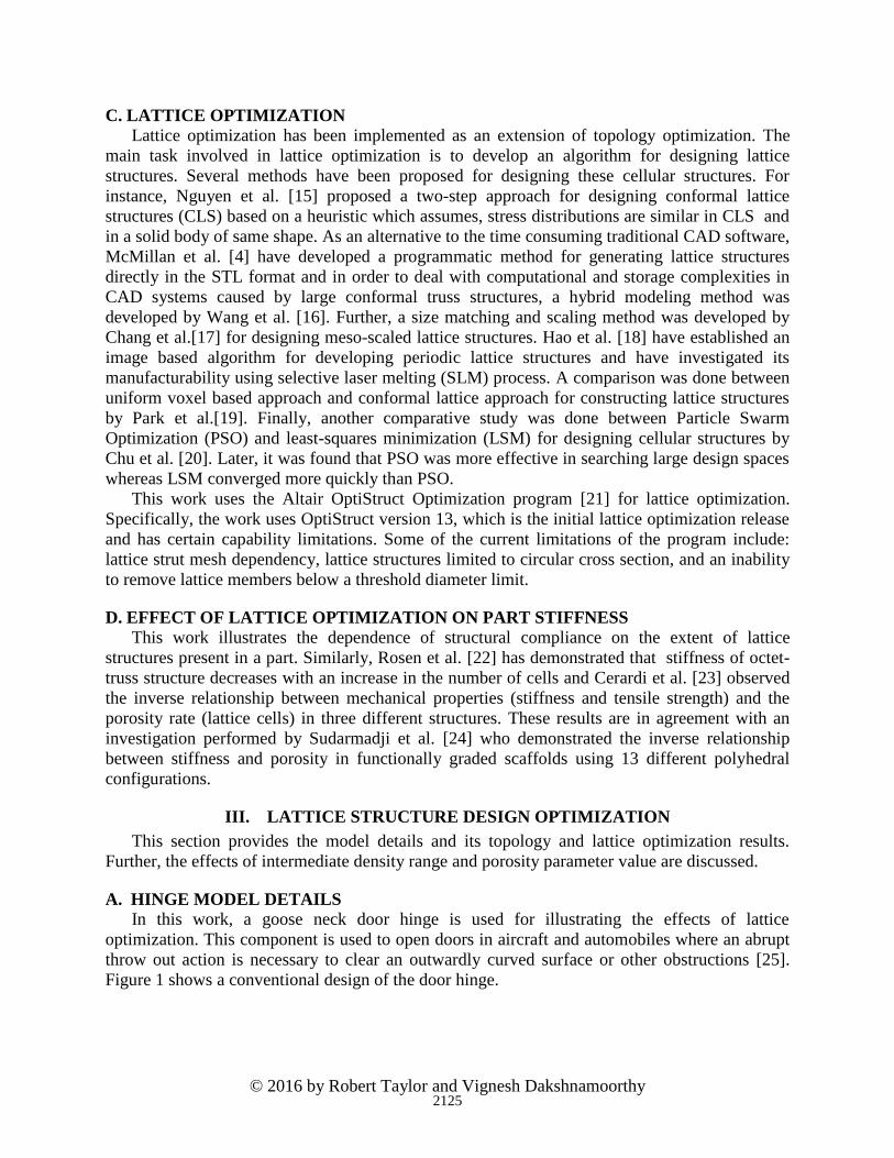
In this work, a goose neck door hinge is used for illustrating the effects of lattice
optimization. This component is used to open doors in aircraft and automobiles where an abrupt
throw out action is necessary to clear an outwardly curved surface or other obstructions [25].
Figure 1 shows a conventional design of the door hinge.
2125
© 2016 by Robert Taylor and Vignesh Dakshnamoorthy
4
Figure 1: Conventional design of goose neck door hinge
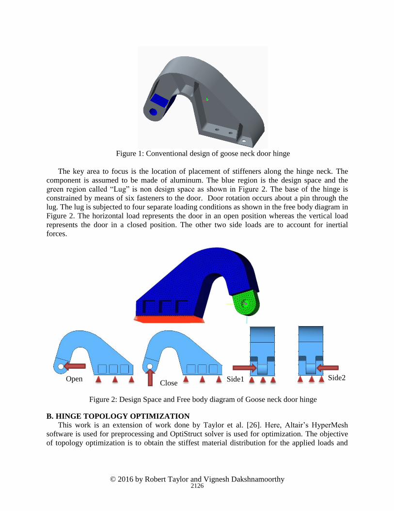
The key area to focus is the location of placement of stiffeners along the hinge neck. The
component is assumed to be made of aluminum. The blue region is the design space and the
green region called “Lug” is non design space as shown in Figure 2. The base of the hinge is
constrained by means of six fasteners to the door. Door rotation occurs about a pin through the
lug. The lug is subjected to four separate loading conditions as shown in the free body diagram in
Figure 2. The horizontal load represents the door in an open position whereas the vertical load
represents the door in a closed position. The other two side loads are to account for inertial
forces.
Figure 2: Design Space and Free body diagram of Goose neck door hinge
B. HINGE TOPOLOGY OPTIMIZATION
This work is an extension of work done by Taylor et al. [26]. Here, Altair’s HyperMesh
software is used for preprocessing and OptiStruct solver is used for optimization. The objective
of topology optimization is to obtain the stiffest material distribution for the applied loads and
Open Close
Side1 Side2
2126
© 2016 by Robert Taylor and Vignesh Dakshnamoorthy
5
boundary conditions as shown in Figure 2. The OptiStruct solver is based on DRCO (Design
variable, Response, design Constraint and Objective function) approach.
OptiStruct uses a density based approach to solve topological optimization problems [27].
Under this method, the element density is used as a design variable that should ideally take a
value of 0 (void) or 1 (solid), which would make it a discrete variable leading to higher
computational needs. In order to bypass this, element density is treated as a continuous variable
between 0 and 1 and any intermediate value represents fictitious porous material, which is not
meaningful in conventional materials. Hence, these intermediate density values are penalized,
forcing the final design toward element densities of 0 and 1.
The hinge optimization study uses volume fraction and weighted compliance responses.
Volume fraction refers to the percent of initial design space to be maintained in the final solution
and weighted compliance is the sum of compliance of four individual load cases. Both the
responses are global and are defined for the whole structure. A specific percent of volume
fraction is used as a constraint and minimizing weighted compliance is the objective function
used to obtain the stiffest configuration. Based on the optimization results for various values of
volume fraction constraints, 40% is chosen for further analysis as it provides better feature
definition compared to other models.
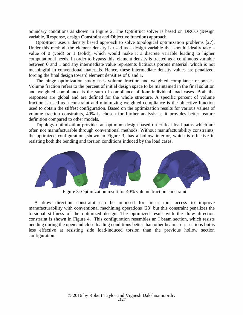
Topology optimization provides an optimum design based on critical load paths which are
often not manufacturable through conventional methods. Without manufacturability constraints,
the optimized configuration, shown in Figure 3, has a hollow interior, which is effective in
resisting both the bending and torsion conditions induced by the load cases.
Figure 3: Optimization result for 40% volume fraction constraint
A draw direction constraint can be imposed for linear tool access to improve
manufacturability with conventional machining operations [28] but this constraint penalizes the
torsional stiffness of the optimized design. The optimized result with the draw direction
constraint is shown in Figure 4. This configuration resembles an I beam section, which resists
bending during the open and close loading conditions better than other beam cross sections but is
less effective at resisting side load-induced torsion than the previous hollow section
configuration.
2127

© 2016 by Robert Taylor and Vignesh Dakshnamoorthy
6
Figure 4: Optimization result – 40% volume fraction with draw direction in Z axis and no
holes constraint
C. HINGE LATTICE OPTIMIZATION
Lattice optimization provides a method to create solid components combined with lattice
structures, which can potentially leverage additive manufacturing capabilities. Lattice
optimization is a two-step approach [29] as shown in Figure 5.
Figure 5: Lattice Optimization Flowchart.
Whereas in regular topology optimization, the intermediate density elements are treated as
fictitious material and are penalized into voids and pure solids, in lattice optimization, these
intermediate density elements are converted into lattice structures using a two phase process.
During the first phase, regular topology optimization is carried out, except that intermediate
density elements are not penalized and are retained within the model [29]. The range of
intermediate density elements to be present can be controlled and it will be discussed in the next
sub-section. In the second phase, the omitted intermediate density element edges are converted
into lattice rod elements and the end diameters are sized based on a stress constraint for further
fine tuning. In order to perform lattice optimization, the LATTICE command is included in the
DTPL bulk data entries as shown in Figure 6.
Figure 6: Bulk data section in .fem file
Regular Topology Optimization
•Include intermediate density elements
Lattice Optimization
•Convert intermediate density elements into lattice struts
•Size lattice members
2128

© 2016 by Robert Taylor and Vignesh Dakshnamoorthy
7
Inclusion of the LATTICE command allows the user to specify the cell structure, lower and
upper bound for intermediate densities and stress constraint values for lattice sizing. Density
values below the lower bound “LB” will be converted into void and values above the upper
bound “UB” will be converted into solids. Elements between LB and UB are converted into 1D
simple beam elements (Type ROD) with diameters proportional to the density of the
intermediate density elements that were replaced [29]. Figure 7 shows the lattice optimized result
and the sized lattice end diameters. The limitations of the initial lattice optimization
implementation in OptiStruct version 13.0 can be seen in the mesh dependent lattice members
and the inability to control the orientation and lattice cell configurations. Despite these
limitations, this lattice optimization capability enables the component stiffness study executed in
this work.
Figure 7: Lattice optimized hinge and sized lattice end diameters.
1. EFFECT OF RANGE OF INTERMEDIATE DENSITY ELEMENTS
The use of lattice structures can reduce component weight but it should be noted that lattice
structures display lower stiffness per volume compared to fully dense material which increases
the compliance. Hence, the amount of increase in model compliance depends upon the density
range of intermediate elements present which are later converted into lattice structures. A stress
constraint of 20 ksi is constantly used throughout this work for sizing the lattice diameters in the
second phase of optimization. The increase in compliance relative to the range of intermediate
density elements is shown in Figure 8. The open and close loading conditions drive the design in
very similar trends and hence the plot of compliance vs intermediate density element range is
explained only for open loading condition. It can be seen from the graph that the compliance
steadily increases as the upper bound of the intermediate density range increases, which means
higher the upper bound the larger the number of lattice structures and higher the compliance.
2129

© 2016 by Robert Taylor and Vignesh Dakshnamoorthy
8
Figure 8: Compliance Vs Intermediate Density Elements
Range for Open Loading Condition
The trend which is observed in Open and Closed loading conditions cannot be applied to the
side loads because side loads puts the hinge under torsion whereas Open and Closed loading
conditions causes bending. A box type structure as shown in Figure 3 would prove efficient for
resisting torsion but as the draw direction constraint is imposed in lattice optimization, material
along the sides is removed and replaced with lattice structures that increase the compliance for
the side loads. The magnitude of the increase remains more or less the same throughout the
entire range of intermediate densities studied as shown in Figure 9. During Open or Closed
loading, the lattice elements resist shear and during Side loading, they resist twisting. Both sets
of load cases drives the design differently and it can be observed in plots Figure 8 and Figure 9.
Figure 9: Compliance Vs Intermediate Density Elements
Range for Side Loading Condition
0%
10%
20%
30%
40%
50%
60%
70%
80%
10-30% 10-50% 20-50% 40-50% 10-60% 30-60% 20-70% 10-80%
Percentage increase in compliance for Open load case
0%
20%
40%
60%
80%
100%
10-30% 10-50% 20-50% 40-50% 10-60% 30-60% 20-70% 10-80%
Percentage increase in compliance for Side load cases
2130

© 2016 by Robert Taylor and Vignesh Dakshnamoorthy
9
2. EFFECT OF POROSITY PARAMETER
From the previous section, it is shown that compliance of the model depends upon the
amount of lattice structures present, which is controlled by specifying the range of intermediate
density elements. Another way to control the amount of lattice structures present is by using the
porosity parameter [29]. The porosity parameter controls the penalization of intermediate density
elements in the first phase of optimization. It is very similar to penalization which occurs during
regular topology optimization except that intermediate density elements are retained in the
model. Three options are available for this design optimization parameter: High, Medium and
Low.
If the Porosity value is High, then there is no penalty applied which leads to a larger amount
of intermediate density elements in the first phase, resulting in a high volume fraction [29] of
lattice structures in the final design. It is to be noted that the model will have very high
compliance due to the large amount of lattice structures. For a Medium porosity value, the
penalty applied is 1.25 which leads to reduced lattice structure zones compared to the previous
option. Both High and Medium options are preferred in applications where the component
porosity is desired. For instance, in the case of a biomedical implants, porosity helps in the
growth of tissues over the implants [22]. When the porosity value is Low, a natural penalty of 1.8
is applied which generates a further reduction in intermediate density elements in the first phase
and leads to a design with very low lattice zones and mostly fully dense material distribution.
This option is preferred in obtaining a stiffest design (compliance minimization problems). The
variation in porosity in shown in Figure 10 for lattice optimized model with 10 to 80%
intermediate density element range.
Figure 10: Variation in Porosity parameter: High, Medium and Low
Though the above model has a very high intermediate density range of 10 to 80%, it should
be noticed that the amount of lattice structures reduces drastically as we move from High to Low
and hence there is a decrease in compliance as shown in Figure 11. Also, for the low porosity
option, the lattice structures are concentrated in the area of stiffeners as predicted by the topology
optimized result from Figure 4.
High Porosity Medium Porosity Low porosity
2131

© 2016 by Robert Taylor and Vignesh Dakshnamoorthy
10
Figure 11: Increase in compliance vs Load cases for various
porosity options
IV. SIZING OPTIMIZATION AND LATTICE STRUCTURES
Shell model created from the topology optimization result and other model variants with
lattice structures along with its sizing optimization results are discussed in this section.
A. HINGE SHELL MODEL DETAILS
Sizing optimization is required after obtaining an optimized topology result in order to
determine geometrical parameters such as plate thickness for a 2D shell element or diameter for
a lattice member is determined. In sizing optimization, the structural connectivity of the model
determined during topology optimization remains fixed throughout optimization process [30].
Whereas minimum compliance design in topology optimization adds material along critical load
paths and provides the stiffest material distribution in the model, it does not take strength or
stability requirements into consideration. Hence, a shell model as shown in Figure 12 is
developed from the topology-optimized result and is size-optimized by taking strength, stability
and displacement constraints into account.
Figure 12: Shell model of the Hinge with Stiffeners
Similar to the topology optimization model, the shell model is also constrained by means of
six fasteners at its base and has the same loading conditions as shown in Figure 2. Gap elements
are used at the base of this model as an interface element between two faces of the structure. Gap
elements are one-dimensional elements defined by two nodes and are capable of transferring
0%
10%
20%
30%
40%
50%
60%
70%
80%
90%
High Medium Low
% In
cre
ase
in C
om
plia
nce
Open
Close
Side
2132

© 2016 by Robert Taylor and Vignesh Dakshnamoorthy
11
only axial forces (tension and compression) [31]. Here, initially the gap between the base of the
hinge and the door is assumed to be closed and there is a load transfer only when the gap
elements are in compression (closed condition).
B. HINGE MODEL VARIATION AND SIZING OPTIMIZATION
In order to understand the effect of the displacement constraint on optimized lattice structure,
two other models were created apart from the Shell and Stiffener model (Model-I) shown in
Figure 12. Model-II and Model-III consist of lattice structures in place of stiffeners, as shown in
Figure 13, with the lattice structures imported from the lattice optimization result. Optimized
lattice structures were used from the 10-80% intermediate density range configuration and the
low porosity option. The main difference between Model-II and Model-III is the diameter of
lattice structures. In Model-II, the diameter of lattice structures are the end diameters from the
lattice optimized result whereas in Model-III, the lattice structures are divided into 3 sections
along the neck of the hinge: forward, mid and backward region and corresponding sizing
variables are created. During the optimization, each section is sized individually so that all the
lattice members in a single section have the same diameter.
Figure 13: Shell model of the Hinge with Lattice Structures
In order to transmit the load from the upper flange to lower flange through lattice structures,
the nodes along edges of lattice structure are selected and connected to the flanges by using rigid
RBE2 elements, which rigidly transmit displacement from one node to another.
Similar to topology optimization, OptiStruct uses the DRCO approach for sizing optimization
as well. The plate thickness of 2D shell elements and diameters of 1D lattice members are the
design variables. Stress, displacement and mass responses are created. Stress constraints of
max/min principal stress within ±40 ksi and a displacement constraint of 0.03 in. are applied for
all three model variations. For Model-III, tension and compression stresses of 40 ksi and 20 ksi,
respectively, are given as constraints for sizing the lattice members. The buckling eigenvalue is
constrained to be greater than 1.0 to ensure flanges and stiffeners remain stable under the design
loads. Finally, minimizing the mass is the objective function for this problem and sizing
optimization is performed.
The resulting optimized design satisfies all stress, displacement, and stability constraints.
Figures 14 -16 show Von Mises stress plots for all three models.. From the lattice stress plots, a
small number of lattice members reach peak stress along the edges where they are tied to the
2133

© 2016 by Robert Taylor and Vignesh Dakshnamoorthy
12
shell flanges using RBE2 elements. Figure 17 shows the resulting optimized shell thicknesses
for all three models.
Figure 14: Model-I Von Mises stress plot with deformation
for Open, Closed and Side load cases
Figure 15: Model-II Von Mises stress plot for topology sized lattice members
for Open, Closed and Side load cases
Figure 16: Model-III Von Mises stress plot for three zone sized lattice members
for Open, Closed and Side load cases
Figure 17: Thickness plot for Model-I, Model-II and Model-III
2134

© 2016 by Robert Taylor and Vignesh Dakshnamoorthy
13
C. MASS COMPARISON FOR VARIOUS DISPLACEMENT CONSTRAINTS
As mentioned previously, though the use of lattice structures reduces the mass of component
significantly, it also increases its compliance. In order to benefit from the usage of lattice
structures, it is necessary to understand the relationship between mass and magnitude of the
displacement constraint of the component. For this purpose, all 3 models were size-optimized for
increasing displacement constraint values, holding stress and buckling constraints as previously
set, and their optimized mass values were recorded. Figure 18 shows the optimized mass result
versus displacement constraint magnitude.
Figure 18: Displacement vs Mass for three model variations
Table 1: Mass (lbs) and %Lattice benefit for various
Displacement constraints
Table 1 provides information about mass for all three model variations for increasing
displacement values. Here, %lattice benefit denotes the percentage reduction of mass by
comparing Model-I and Model-II. With the initial tightly constrained diplacement values,
essentially no benefit is obtained from the lattice optimization—the initial negative values are
within numerical noise and model idealization error. Although the mass of Model-I and Model-
II are almost the same initially, mass reduction increases to around 14% as the displacement
constraint is relaxed. From Figure 18, the relation between displacement and mass is similar in
0.000
1.000
2.000
3.000
4.000
5.000
6.000
7.000
8.000
0 . 0 3 0 . 0 6 0 . 0 9 0 . 1 0 . 5 1 1 . 5
MA
SS
DISPLACEMENT CONSTRAINT
DISPLACEMENT VS MASS
Model-I
Model-II
Model-III
2135

© 2016 by Robert Taylor and Vignesh Dakshnamoorthy
14
all three design variants as expected, i.e. the mass of the component reduces if the displacement
constraint is relaxed. The displacement vs. mass curve for Model I and II flattens after 0.5 in.
displacement constraint magnitude because the thickness of the shell elements reaches a lower
bound value of 0.05 in. during sizing optimization. From Figure 18, it can be seen that Model-III
is comparatively heavier than the other models. Due to large number of lattice members, it is
difficult to manually hand pick each lattice and create individual design variables. For this
purpose, they were segregated into three sections and sized section wise. As the lattices are sized
section wise based on stress, one or two lattice members determine the size of whole section
which reduces the design freedom and leads to heavier weight.
V. CONCLUSION AND FUTURE WORK
This work studied the effects of lattice structure configurations on component stiffness in a
two phase effort. In both phases, a goose neck door hinge with four load cases is used for
demonstrating the effects of lattice optimization. In the first phase, topology optimization of the
model provides an I beam configuration which resists bending during Open and Closed loading
conditions and determines the location of stiffeners. Later, topology optimization is extended to
lattice optimization and it should be noted that lattice structures are formed primarily in the place
of stiffeners. Compliance of the model depends on the amount of lattice members present which
can be controlled using two parameters: range of intermediate density elements and the porosity
parameter. Figure 8 provides the relationship between the range of intermediate density elements
and model compliance. It should be observed that model compliance increases as the density
range increases. Similarly, the porosity parameter can be used to control the amount of lattice
structures present, which in turn determines the compliance of the model. There are three
porosity options: High, Medium and Low. From Figure 8 and Figure 11, we can come to a
conclusion that compliance of the model depends upon the lattice volume fraction, i.e., the
higher the number of lattice members, the higher the compliance.
The second phase of the work involves fine tuning of the design. To understand the
relationship between lattice structures and displacement constraint, three shell model variations
with stiffeners and lattice structures are created where the lattice members are imported from low
porosity lattice optimization result. These models are size optimized for increasing displacement
constraint values and their corresponding mass values are recorded. From Figure 18 and Table 1,
it can be noticed that mass of the component reduces as we increase the displacement constraint
value and this trend is similar in all three model variations. About 14% mass reduction can be
observed between the model with stiffeners and the model with lattice structures once we
increase the displacement value. Based on the above observations, lattice structures can be
implemented in solid models where low weight is preferred and at the same time relaxation in
displacement constraint is acceptable.
HyperMesh and OptiStruct version 13.0 was used for simulation purposes in this paper. The
next version 14.0 has been released and work needs to be done to investigate the changes in
results by using the enhancements of latest version. Some of the updated features in lattice
optimization include use of tapered lattice members, lattice smoothing, and re-meshing features.
Also, work is planned to study lattice structures designs in other applications where they can be
used to reduce the component weight without affecting its stiffness. Future work will also
examine methods to control the directionality, density, and cell configuration and to address the
stress concentrations in the lattice structures which might lead to fatigue failure.
2136
© 2016 by Robert Taylor and Vignesh Dakshnamoorthy
15
VI. ACKNOWLEDGEMENTS
The authors wish to thank Altair Engineering, especially Blaise Cole, Hedison Mui, and
Chayan Basak, for their support of this work.
VII. REFERENCES
[1] I. Gibson, D. W. Rosen, and B. Stucker, Additive Manufacturing Technologies, Second
Edi. Springer, 2010.
[2] D. Brackett, I. Ashcroft, and R. Hague, “Topology optimization for additive
manufacturing,” Solid Free. Fabr. Symp., pp. 348–362, 2011.
[3] W. Dias and D. Anand, “Design and Optimization of Lattice Structure for 3D Printing
using Altair OptiStruct,” 2015. [Online]. Available:
http://insider.altairhyperworks.com/design-and-optimization-of-lattice-structures-for-3d-
printing-using-altair-optistruct/. [Accessed: 23-May-2016].
[4] M. McMillan, M. Jurg, M. Leary, and M. Brandt, “Programmatic Lattice Generation for
Additive Manufacture,” Procedia Technol., vol. 20, no. July, pp. 178–184, 2015.
[5] Y. Tang and Y. F. Zhao, “Lattice-skin Structures Design with Orientation Optimization,”
Proc. Solid Free. Fabr. Symp., pp. 1378–1393, 2015.
[6] J. N. Stuecker, J. C. Iii, and E. Smay, “Robocasting Periodic Lattices For Advanced
Filtration,” Solid Free. Fabr. Symp., pp. 561–566, 2001.
[7] J. R. Heidrich, V. Gervasi, and S. Kumpaty, “Synthesis of a Compact Tetralattice Heat
Exchanger Using Solid Freeform Fabrication and Comparison Testing Against a Tube
Heat Exchanger,” Solid Free. Fabr. Symp., pp. 567–575, 2001.
[8] A. Hussein, L. Hao, C. Yan, R. Everson, and P. Young, “Advanced lattice support
structures for metal additive manufacturing,” J. Mater. Process. Technol., vol. 213, no. 7,
pp. 1019–1026, 2013.
[9] O. Iyibilgin, C. Yigit, and M. C. Leu, “Experimental investigation of different cellular
lattice structures manufactured by fused deposition modeling,” Solid Free. Fabr. Symp.,
pp. 895–907, 2013.
[10] I. Maskery, A. O. Aremu, M. Simonelli, C. Tuck, R. D. Wildman, I. A. Ashcroft, and R. J.
M. Hague, “The BCC unit cell for latticed SLM parts ; mechanical properties as a function
of cell size .,” Solid Free. Fabr. Symp., pp. 688–701, 2014.
[11] V. S. Deshpande, N. A. Fleck, and M. F. Ashby, “Effective properties of the octet-truss
lattice material,” J. Mech. Phys. Solids, vol. 49, no. 8, pp. 1747–1769, 2001.
[12] “Topology Optimization,” Wikipedia, 20-May-2016. [Online]. Available:
https://en.wikipedia.org/wiki/Topology_optimization. [Accessed: 01-Jun-2016].
[13] M. P. Bendsøe and N. Kikuchi, “Generating optimal topologies in structural design using
a homogenization method,” Comput. Methods Appl. Mech. Eng., vol. 71, no. 2, pp. 197–
224, 1988.
[14] G. I. N. Rozvany, “A critical review of established methods of structural topology
optimization,” Struct. Multidiscip. Optim., vol. 37, no. 3, pp. 217–237, 2009.
[15] J. Nguyen, S. Park, D. W. Rosen, L. Folgar, and J. Williams, “Conformal Lattice Structure
Design and Fabrication,” Sff, pp. 138–161, 2012.
[16] H. V. Wang, Y. Chen, and D. W. Rosen, “A Hybrid Geometric Modeling Method for
Large Scale Conformal Cellular Structures,” ASME Comput. Inf. Eng. Conf., vol. 2005,
pp. 421–427, 2005.
[17] P. S. Chang and D. W. Rosen, “The size matching and scaling method: A synthesis
2137

© 2016 by Robert Taylor and Vignesh Dakshnamoorthy
16
method for the design of mesoscale cellular structures,” Int. J. Comput. Integr. Manuf.,
2013.
[18] L. Hao, D. Raymont, C. Yan, A. Hussein, and P. Young, “Design and additive
manufacturing of cellular lattice structures,” Int. Conf. Adv. Res. Virtual Rapid Prototyp.,
no. May 2016, pp. 249–254, 2012.
[19] S. Park, D. W. Rosen, and C. E. Duty, “Comparing Mechanical and Geometrical
Properties of Lattice Structure Fabricated using Electron Beam Melting,” Solid Free.
Fabr. Symp., pp. 1359–1370, 2014.
[20] J. Chu, S. Engelbrecht, G. Graf, and D. W. Rosen, “A comparison of synthesis methods
for cellular structures with application to additive manufacturing,” Rapid Prototyp. J., vol.
16, no. 4, pp. 275–283, 2010.
[21] “Altair OptiStruct,” Altair HyperWorks, 2016. [Online]. Available:
http://www.altairhyperworks.com/product/OptiStruct. [Accessed: 30-May-2016].
[22] D. Rosen, S. Johnston, and M. Reed, “Design of General Lattice Structures for
Lightweight and Compliance Applications,” Rapid Manuf. Conf., pp. 1–14, 2006.
[23] A. Cerardi, M. Caneri, R. Meneghello, and G. Concheri, “Mechanical characterization of
polyamide porous specimens for the evaluation of emptying strategies in Rapid
Prototyping,” in 37th, International matador conference; 2012; Manchester, 2012.
[24] N. Sudarmadji, J. Y. Tan, K. F. Leong, C. K. Chua, and Y. T. Loh, “Investigation of the
mechanical properties and porosity relationships in selective laser-sintered polyhedral for
functionally graded scaffolds,” Acta Biomater., vol. 7, no. 2, pp. 530–537, 2011.
[25] E. B. G. Lefevre, “Gooseneck concealed hinge,” US2132266 A, 1938.
[26] R. Taylor, D. Durocher, and R. Yancey, “Teaching Aerospace Design Optimization,” in
2015 Americas Altair Technology Conference, 2015, pp. 10–13.
[27] “Design variables for topology optimization,” Altair Hyperworks. [Online]. Available:
https://connect.altair.com/CP/kb-view.html?kb=128250. [Accessed: 08-Jun-2016].
[28] “Draw Direction Constraints for Topology Optimization,” Altair HyperWorks, 2016.
[Online]. Available: https://connect.altair.com/CP/kb-view.html?kb=128263. [Accessed:
08-Jun-2016].
[29] “Lattice Structure Optimization,” Altair HyperWorks, 2016. [Online]. Available:
https://connect.altair.com/CP/kb-view.html?kb=128259. [Accessed: 13-Jun-2016].
[30] M. P. Bendsøe and O. Sigmund, Topology optimization: theory, methods, and
applications, vol. 2nd Editio, no. 724. 2003.
[31] “OptiStruct User Guide 14.0,” Altair Connect, 2016. [Online]. Available:
https://connect.altair.com/CP/kb-view.html?f=2&kb=128167. [Accessed: 08-Jun-2016].
2138