Automated Indirect Transport of Biological Cells Using ...
7
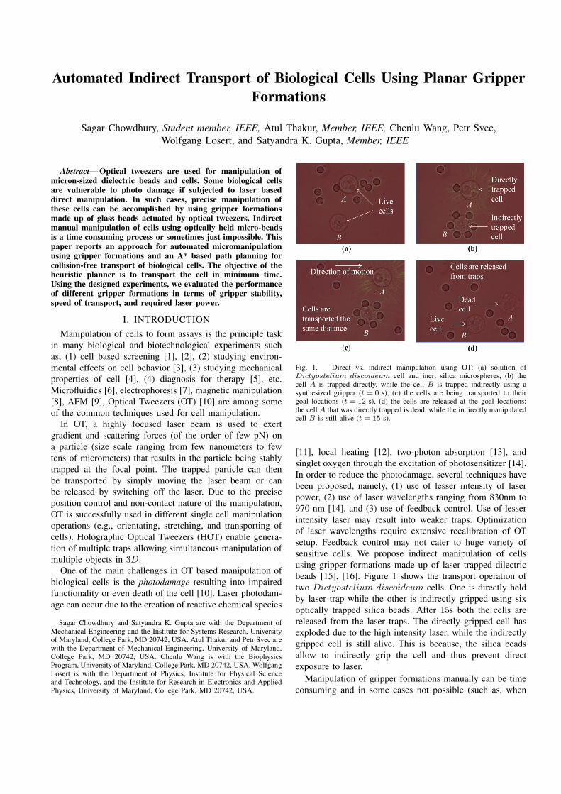
Automated Indirect Transport of Biological Cells Using Planar Gripper Formations Sagar Chowdhury, Student member, IEEE, Atul Thakur, Member, IEEE, Chenlu Wang, Petr Svec, Wolfgang Losert, and Satyandra K. Gupta, Member, IEEE Abstract— Optical tweezers are used for manipulation of micron-sized dielectric beads and cells. Some biological cells are vulnerable to photo damage if subjected to laser based direct manipulation. In such cases, precise manipulation of these cells can be accomplished by using gripper formations made up of glass beads actuated by optical tweezers. Indirect manual manipulation of cells using optically held micro-beads is a time consuming process or sometimes just impossible. This paper reports an approach for automated micromanipulation using gripper formations and an A* based path planning for collision-free transport of biological cells. The objective of the heuristic planner is to transport the cell in minimum time. Using the designed experiments, we evaluated the performance of different gripper formations in terms of gripper stability, speed of transport, and required laser power. I. INTRODUCTION Manipulation of cells to form assays is the principle task in many biological and biotechnological experiments such as, (1) cell based screening [1], [2], (2) studying environ- mental effects on cell behavior [3], (3) studying mechanical properties of cell [4], (4) diagnosis for therapy [5], etc. Microfluidics [6], electrophoresis [7], magnetic manipulation [8], AFM [9], Optical Tweezers (OT) [10] are among some of the common techniques used for cell manipulation. In OT, a highly focused laser beam is used to exert gradient and scattering forces (of the order of few pN) on a particle (size scale ranging from few nanometers to few tens of micrometers) that results in the particle being stably trapped at the focal point. The trapped particle can then be transported by simply moving the laser beam or can be released by switching off the laser. Due to the precise position control and non-contact nature of the manipulation, OT is successfully used in different single cell manipulation operations (e.g., orientating, stretching, and transporting of cells). Holographic Optical Tweezers (HOT) enable genera- tion of multiple traps allowing simultaneous manipulation of multiple objects in 3D. One of the main challenges in OT based manipulation of biological cells is the photodamage resulting into impaired functionality or even death of the cell [10]. Laser photodam- age can occur due to the creation of reactive chemical species Sagar Chowdhury and Satyandra K. Gupta are with the Department of Mechanical Engineering and the Institute for Systems Research, University of Maryland, College Park, MD 20742, USA. Atul Thakur and Petr Svec are with the Department of Mechanical Engineering, University of Maryland, College Park, MD 20742, USA. Chenlu Wang is with the Biophysics Program, University of Maryland, College Park, MD 20742, USA. Wolfgang Losert is with the Department of Physics, Institute for Physical Science and Technology, and the Institute for Research in Electronics and Applied Physics, University of Maryland, College Park, MD 20742, USA. Fig. 1. Direct vs. indirect manipulation using OT: (a) solution of Dictyostelium discoideum cell and inert silica microspheres, (b) the cell A is trapped directly, while the cell B is trapped indirectly using a synthesized gripper (t =0 s), (c) the cells are being transported to their goal locations (t = 12 s), (d) the cells are released at the goal locations; the cell A that was directly trapped is dead, while the indirectly manipulated cell B is still alive (t = 15 s). [11], local heating [12], two-photon absorption [13], and singlet oxygen through the excitation of photosensitizer [14]. In order to reduce the photodamage, several techniques have been proposed, namely, (1) use of lesser intensity of laser power, (2) use of laser wavelengths ranging from 830nm to 970 nm [14], and (3) use of feedback control. Use of lesser intensity laser may result into weaker traps. Optimization of laser wavelengths require extensive recalibration of OT setup. Feedback control may not cater to huge variety of sensitive cells. We propose indirect manipulation of cells using gripper formations made up of laser trapped dilectric beads [15], [16]. Figure 1 shows the transport operation of two Dictyostelium discoideum cells. One is directly held by laser trap while the other is indirectly gripped using six optically trapped silica beads. After 15s both the cells are released from the laser traps. The directly gripped cell has exploded due to the high intensity laser, while the indirectly gripped cell is still alive. This is because, the silica beads allow to indirectly grip the cell and thus prevent direct exposure to laser. Manipulation of gripper formations manually can be time consuming and in some cases not possible (such as, when
Transcript of Automated Indirect Transport of Biological Cells Using ...
Automated Indirect Transport of Biological Cells Using Planar GripperFormations
Sagar Chowdhury, Student member, IEEE, Atul Thakur, Member, IEEE, Chenlu Wang, Petr Svec,Wolfgang Losert, and Satyandra K. Gupta, Member, IEEE
Abstract— Optical tweezers are used for manipulation ofmicron-sized dielectric beads and cells. Some biological cellsare vulnerable to photo damage if subjected to laser baseddirect manipulation. In such cases, precise manipulation ofthese cells can be accomplished by using gripper formationsmade up of glass beads actuated by optical tweezers. Indirectmanual manipulation of cells using optically held micro-beadsis a time consuming process or sometimes just impossible. Thispaper reports an approach for automated micromanipulationusing gripper formations and an A* based path planning forcollision-free transport of biological cells. The objective of theheuristic planner is to transport the cell in minimum time.Using the designed experiments, we evaluated the performanceof different gripper formations in terms of gripper stability,speed of transport, and required laser power.
I. INTRODUCTION
Manipulation of cells to form assays is the principle taskin many biological and biotechnological experiments suchas, (1) cell based screening [1], [2], (2) studying environ-mental effects on cell behavior [3], (3) studying mechanicalproperties of cell [4], (4) diagnosis for therapy [5], etc.Microfluidics [6], electrophoresis [7], magnetic manipulation[8], AFM [9], Optical Tweezers (OT) [10] are among someof the common techniques used for cell manipulation.
In OT, a highly focused laser beam is used to exertgradient and scattering forces (of the order of few pN) ona particle (size scale ranging from few nanometers to fewtens of micrometers) that results in the particle being stablytrapped at the focal point. The trapped particle can thenbe transported by simply moving the laser beam or canbe released by switching off the laser. Due to the preciseposition control and non-contact nature of the manipulation,OT is successfully used in different single cell manipulationoperations (e.g., orientating, stretching, and transporting ofcells). Holographic Optical Tweezers (HOT) enable genera-tion of multiple traps allowing simultaneous manipulation ofmultiple objects in 3D.
One of the main challenges in OT based manipulation ofbiological cells is the photodamage resulting into impairedfunctionality or even death of the cell [10]. Laser photodam-age can occur due to the creation of reactive chemical species
Sagar Chowdhury and Satyandra K. Gupta are with the Department ofMechanical Engineering and the Institute for Systems Research, Universityof Maryland, College Park, MD 20742, USA. Atul Thakur and Petr Svec arewith the Department of Mechanical Engineering, University of Maryland,College Park, MD 20742, USA. Chenlu Wang is with the BiophysicsProgram, University of Maryland, College Park, MD 20742, USA. WolfgangLosert is with the Department of Physics, Institute for Physical Scienceand Technology, and the Institute for Research in Electronics and AppliedPhysics, University of Maryland, College Park, MD 20742, USA.
Fig. 1. Direct vs. indirect manipulation using OT: (a) solution ofDictyostelium discoideum cell and inert silica microspheres, (b) thecell A is trapped directly, while the cell B is trapped indirectly using asynthesized gripper (t = 0 s), (c) the cells are being transported to theirgoal locations (t = 12 s), (d) the cells are released at the goal locations;the cell A that was directly trapped is dead, while the indirectly manipulatedcell B is still alive (t = 15 s).
[11], local heating [12], two-photon absorption [13], andsinglet oxygen through the excitation of photosensitizer [14].In order to reduce the photodamage, several techniques havebeen proposed, namely, (1) use of lesser intensity of laserpower, (2) use of laser wavelengths ranging from 830nm to970 nm [14], and (3) use of feedback control. Use of lesserintensity laser may result into weaker traps. Optimizationof laser wavelengths require extensive recalibration of OTsetup. Feedback control may not cater to huge variety ofsensitive cells. We propose indirect manipulation of cellsusing gripper formations made up of laser trapped dilectricbeads [15], [16]. Figure 1 shows the transport operation oftwo Dictyostelium discoideum cells. One is directly heldby laser trap while the other is indirectly gripped using sixoptically trapped silica beads. After 15s both the cells arereleased from the laser traps. The directly gripped cell hasexploded due to the high intensity laser, while the indirectlygripped cell is still alive. This is because, the silica beadsallow to indirectly grip the cell and thus prevent directexposure to laser.
Manipulation of gripper formations manually can be timeconsuming and in some cases not possible (such as, when
simultaneous movements of multiple cells are required). Inthis paper we present an approach for automated transport ofcells using gripper formations. Main challenges encounteredin automated planning for this task include, Brownian mo-tion, dynamical interactions among fluid, beads, and cells,and image processing based measurement uncertainty.
The main contributions of this paper include the following.(i.) We present an automated approach for indirect manip-
ulation including rotation and linear displacement ofbiological cells using planar gripper formations,
(ii.) We present a global path planner based on A* algo-rithm to transport cells using gripper formations alongcollision-free paths.
(iii.) We demonstrate experimental results of the developedautomated indirect cell transport and path planning.
(iv.) We present detailed experimental results of the perfor-mance evaluation of each gripper formation in termsof formation stability, speed of transport, and the usedlaser power.
II. LITERATURE REVIEW
In this section, we will review the literature in the areasof robotic grasping, pushing, and path planning, which areclosely related to the problem of automated indirect transportof a cell.
Robotic grasping involves three issues [17], namely, (1)existence of allowable contacts for form closure [19], [20],(2) criteria for form closure [18], (3) algorithms to determineset of allowable contacts for form closure.
Various grasp synthesis algorithms have been proposed[21], [20]. Another stream of research deals with the qualityof a grasp by developing different metrics [22]. Chowdhuryet al. [15] synthesized a gripper configuration for manipu-lating a cell using HOT in 3D.
Akella and Mason [23] generated open-loop feedbackplans to push a polygonal object using a fence. Balorda andBazd [24] reduced uncertainty in pushing an object ratherthan using expensive fixtures arrangements to compensate forit. Lynch and Mason [25], [26] generated collision-free pathsfor stable pushing of heavy objects with multiple pusherobjects. Rezzoug and Gorce [27] dynamically controlledthe multi-finger pushing operation by considering optimalforce distribution and center of mass acceleration correction.Berretty et al. [28] developed approach to generate sequenceof pushing actions to orient parts in a sensor-less manufac-turing setup. Similar approach was used by [29] to orientparts in any arbitrary orientation.
Koenig and Likhachev [32] used heuristic based searchwith the reuse of past information about the environment forfast replanning in unknown terrains. Ferguson et al. [33]modified the same heuristic based search to enable anytimecapability. Missiuro and Roy [34] in their probabilisticroadmap (PRM) planner made the sampling of the statespace biased to specific state space areas by calculating thecollision probability for certain sampled states. The RapidlyExploring Random Tree (RRT) algorithm was modified byrepresenting the extended nodes by a distribution of states
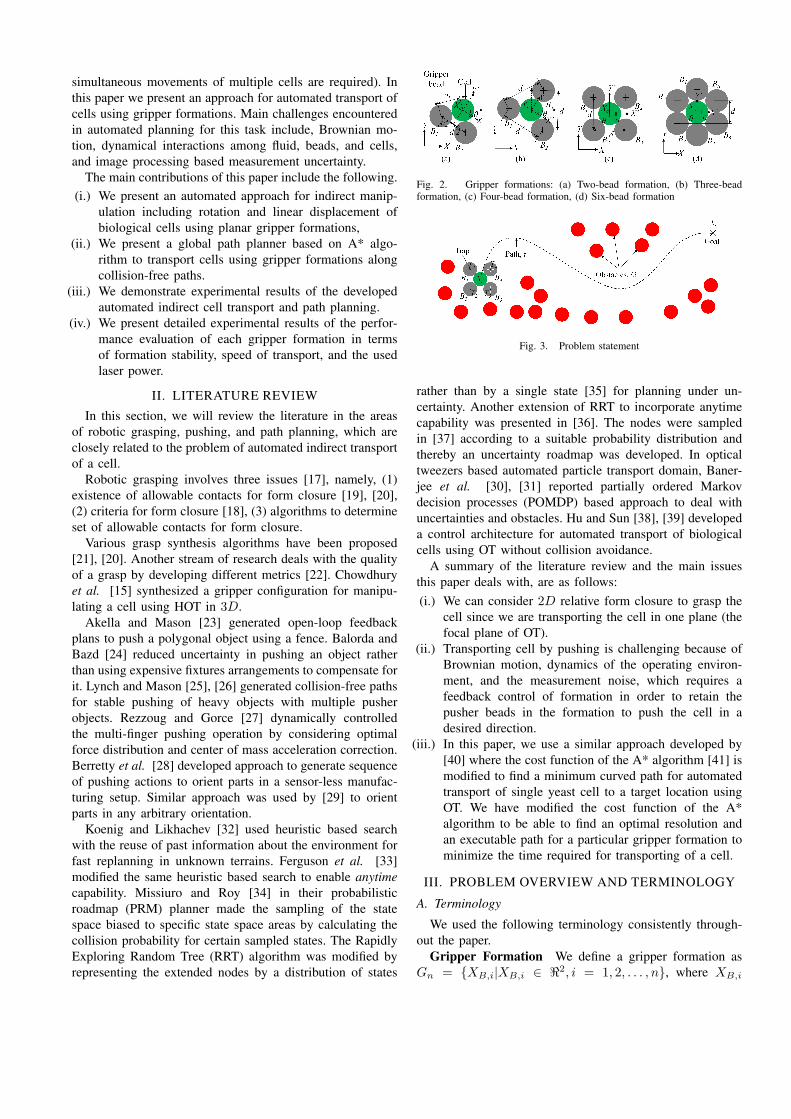
Fig. 2. Gripper formations: (a) Two-bead formation, (b) Three-beadformation, (c) Four-bead formation, (d) Six-bead formation
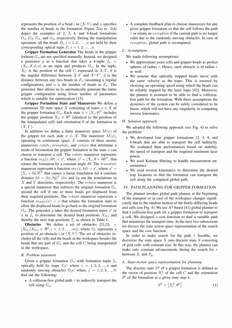
Fig. 3. Problem statement
rather than by a single state [35] for planning under un-certainty. Another extension of RRT to incorporate anytimecapability was presented in [36]. The nodes were sampledin [37] according to a suitable probability distribution andthereby an uncertainty roadmap was developed. In opticaltweezers based automated particle transport domain, Baner-jee et al. [30], [31] reported partially ordered Markovdecision processes (POMDP) based approach to deal withuncertainties and obstacles. Hu and Sun [38], [39] developeda control architecture for automated transport of biologicalcells using OT without collision avoidance.
A summary of the literature review and the main issuesthis paper deals with, are as follows:(i.) We can consider 2D relative form closure to grasp the
cell since we are transporting the cell in one plane (thefocal plane of OT).
(ii.) Transporting cell by pushing is challenging because ofBrownian motion, dynamics of the operating environ-ment, and the measurement noise, which requires afeedback control of formation in order to retain thepusher beads in the formation to push the cell in adesired direction.
(iii.) In this paper, we use a similar approach developed by[40] where the cost function of the A* algorithm [41] ismodified to find a minimum curved path for automatedtransport of single yeast cell to a target location usingOT. We have modified the cost function of the A*algorithm to be able to find an optimal resolution andan executable path for a particular gripper formation tominimize the time required for transporting of a cell.
III. PROBLEM OVERVIEW AND TERMINOLOGY
A. Terminology
We used the following terminology consistently through-out the paper.
Gripper Formation We define a gripper formation asGn = XB,i|XB,i ∈ ℜ2, i = 1, 2, . . . , n, where XB,i
represents the position of a bead i in (X,Y ) and n specifiesthe number of beads in the formation. Figure 2(a) to 2(d)depict the examples of 2, 3, 4, and 6-bead formationsG2, G3, G4, and G6, respectively. During the manipulationoperation, all the beads Bi, i = 1, 2, . . . , n are held by theircorresponding optical traps Ti, i = 1, 2, . . . , n.
Gripper Formation Generator The beads in the gripperforation Gn are not specified manually. Instead, we designeda generator g as a function that takes a 4-tuple fn =(XC , θ, d, n) as an input and produces Gn. In the tuple,XC is the position of the cell C expressed in X-Y , θ isthe angular difference between X-Y and X ′-Y ′, d is thedistance between any two beads in Fn (assuming a regularconfiguration), and n is the number of beads in Fn. Thegenerator thus allows us to automatically generate the entiregripper configuration using fewer number of parameterswhich is suitable for optimization [15].
Gripper Formation State and Maneuvers We define acontinuous 3D state space X consisting of states x ∈ X ofthe gripper formation Gn. Each state x = [Xc, θ]
T includesthe gripper position XC ∈ ℜ2 (identical to the position ofthe manipulated cell) and orientation θ of the formation in(X,Y ).
In addition we define a finite maneuver space M(x) ofthe gripper for each state x ∈ X . The maneuver M(x),operating in continuous space X consists of three atomicmaneuvers rotate, translate, and retain that determine amode of locomotion the gripper formation in the state x canchoose to transport a cell. The rotate maneuver representsa function mR(x, δθ) = x′, where x′ = [Xc, θ + δθ]T , thatrotates the formation by a constant angle δθ. The translatemaneuver represents a function mT (x, δd) = x′, where x′ =[Xc + δd, θ]T that causes a linear translation for a constantdistance δd = [δx, δy]T (δx and δy are the translations inX and Y directions, respectively). The retain maneuver isa special maneuver that enforces the original formation Gn
around the cell if one or more beads get displaced fromtheir required positions. The retain maneuver represents afunction mRET (x) = x that retains the formation state toallow the displaced beads to go back to the original formationGn. The generator g takes the desired formation states x′ orx in fn to determine the desired bead positions XB,i andthereby the next trap positions Ti as shown in Table I.
Obstacles We define a set of obstacles Ωi|Ωi =[XΩ,i|XΩ,i ∈ ℜ2, i = 1, 2, . . . ,m, where Ωi represents aposition of an obstacle i in (X,Y ). The set of obstacles in-cludes all the cells and the beads in the workspace besides thebeads that are part of Gn and the cell C being manipulatedin the workspace.
B. Problem statement
Given a gripper formation Gn with formation tuple fnoptically held by traps Tis’ where i = 1, 2, 3, ..., n andrandomly moving obstacles Ωjs’ where j = 1, 2, 3, ..., Nfind out the following:
• A collision-free global path τ to indirectly transport thecell using Gn.
• A complete feedback plan to choose maneuvers for anygiven gripper formation so that the cell follows the pathτ or return an exception if the current path is no longervalid due to the randomly moving obstacles. In case ofexception, global path is recomputed.
C. Assumptions
We made following assumptions:• We approximate yeast cells and gripper beads as perfect
spheres of radius r. Hence, each obstacle is of radius ras well.
• We assume that optically trapped beads move withthe same velocity as the traps. This is ensured bychoosing an operating speed using which the beads canbe reliably trapped by the laser traps [42]. Moreover,the planner is assumed to be able to find a collision-free path for the formation. With these assumptions thedynamics of the system can be safely considered to belinear, which will not have any singularity in computinginverse kinematics.
D. Solution approach
We adopted the following approach (see Fig. 4) to solvethe problem:
• We developed four gripper formations (2, 3, 4, and6-bead) that are able to transport the cell indirectly.We evaluated their performances based on stability,the speed of transport and the required minimum laserpower.
• We used Kalman filtering to handle measurement un-certainties.
• We used inverse kinematics to determine the desiredtrap locations so that the formation can transport thecell along the computed global path.
IV. PATH PLANNING FOR GRIPPER FORMATION
The planner invokes global path planner at the beginningof the transport or in case of the workspace changes signifi-cantly due to the random motion of the freely diffusing beadsand cells (see Fig. 4). We use A* based [41] global planner tofind a collision-free path for a gripper formation to transporta cell. We designed a cost function to find a suitable paththat minimizes the transport time. In the next two subsectionswe discuss the state-action space representation of the searchspace and the cost function.
In order to make search for the path τ feasible, wediscretize the state space X into discrete state S consistingof grid cells with constant size. In this way, the planner canmake only constant advancements during the search for τbetween Si and Sg.
A. State-Action space representation for planning
The discrete state Sk of a gripper formation is defined asthe vector of position Xk
c of the cell C and the orientationθk of the formation at a given time step k.
Sk =[Xk
c , θk]
(1)
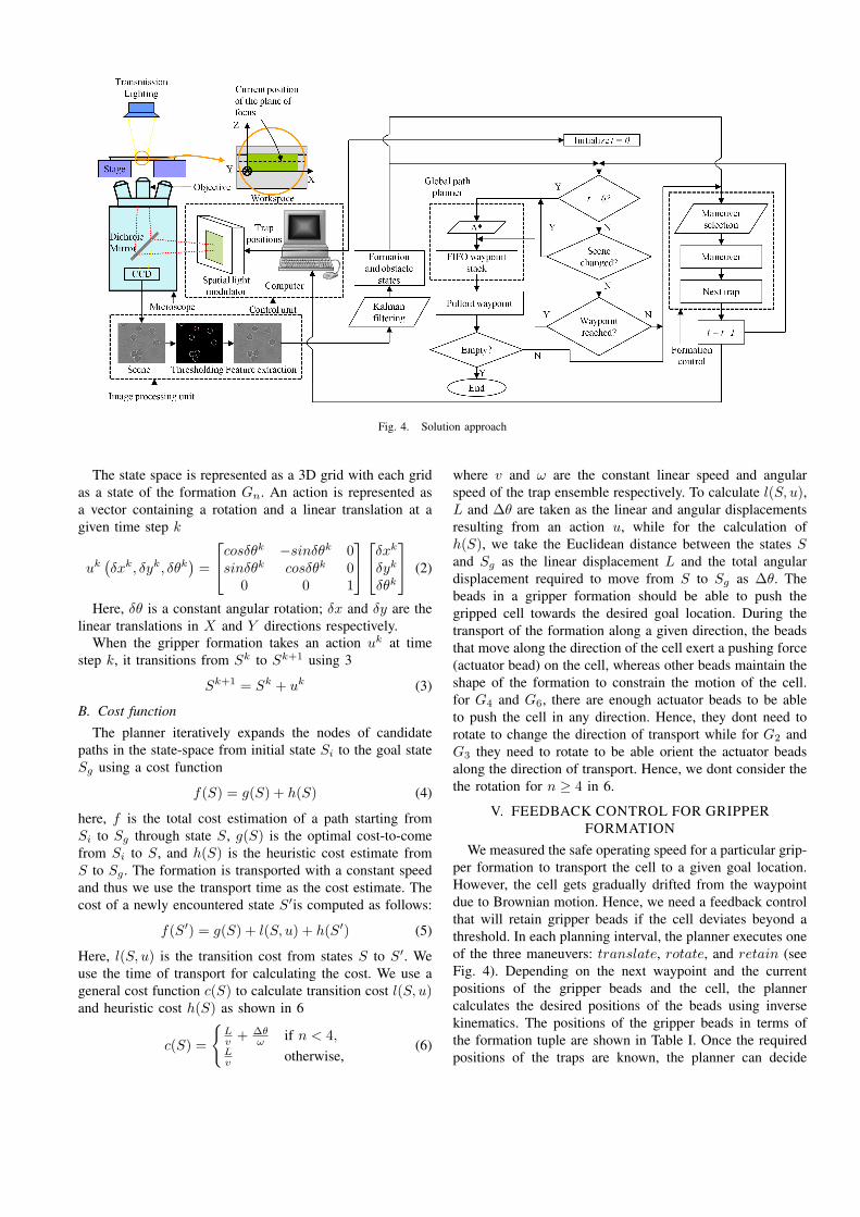
Fig. 4. Solution approach
The state space is represented as a 3D grid with each gridas a state of the formation Gn. An action is represented asa vector containing a rotation and a linear translation at agiven time step k
uk(δxk, δyk, δθk
)=
cosδθk −sinδθk 0sinδθk cosδθk 0
0 0 1
δxk
δyk
δθk
(2)
Here, δθ is a constant angular rotation; δx and δy are thelinear translations in X and Y directions respectively.
When the gripper formation takes an action uk at timestep k, it transitions from Sk to Sk+1 using 3
Sk+1 = Sk + uk (3)
B. Cost function
The planner iteratively expands the nodes of candidatepaths in the state-space from initial state Si to the goal stateSg using a cost function
f(S) = g(S) + h(S) (4)
here, f is the total cost estimation of a path starting fromSi to Sg through state S, g(S) is the optimal cost-to-comefrom Si to S, and h(S) is the heuristic cost estimate fromS to Sg . The formation is transported with a constant speedand thus we use the transport time as the cost estimate. Thecost of a newly encountered state S′is computed as follows:
f(S′) = g(S) + l(S, u) + h(S′) (5)
Here, l(S, u) is the transition cost from states S to S′. Weuse the time of transport for calculating the cost. We use ageneral cost function c(S) to calculate transition cost l(S, u)and heuristic cost h(S) as shown in 6
c(S) =
Lv + ∆θ
ω if n < 4,Lv otherwise,
(6)
where v and ω are the constant linear speed and angularspeed of the trap ensemble respectively. To calculate l(S, u),L and ∆θ are taken as the linear and angular displacementsresulting from an action u, while for the calculation ofh(S), we take the Euclidean distance between the states Sand Sg as the linear displacement L and the total angulardisplacement required to move from S to Sg as ∆θ. Thebeads in a gripper formation should be able to push thegripped cell towards the desired goal location. During thetransport of the formation along a given direction, the beadsthat move along the direction of the cell exert a pushing force(actuator bead) on the cell, whereas other beads maintain theshape of the formation to constrain the motion of the cell.for G4 and G6, there are enough actuator beads to be ableto push the cell in any direction. Hence, they dont need torotate to change the direction of transport while for G2 andG3 they need to rotate to be able orient the actuator beadsalong the direction of transport. Hence, we dont consider thethe rotation for n ≥ 4 in 6.
V. FEEDBACK CONTROL FOR GRIPPERFORMATION
We measured the safe operating speed for a particular grip-per formation to transport the cell to a given goal location.However, the cell gets gradually drifted from the waypointdue to Brownian motion. Hence, we need a feedback controlthat will retain gripper beads if the cell deviates beyond athreshold. In each planning interval, the planner executes oneof the three maneuvers: translate, rotate, and retain (seeFig. 4). Depending on the next waypoint and the currentpositions of the gripper beads and the cell, the plannercalculates the desired positions of the beads using inversekinematics. The positions of the gripper beads in terms ofthe formation tuple are shown in Table I. Once the requiredpositions of the traps are known, the planner can decide
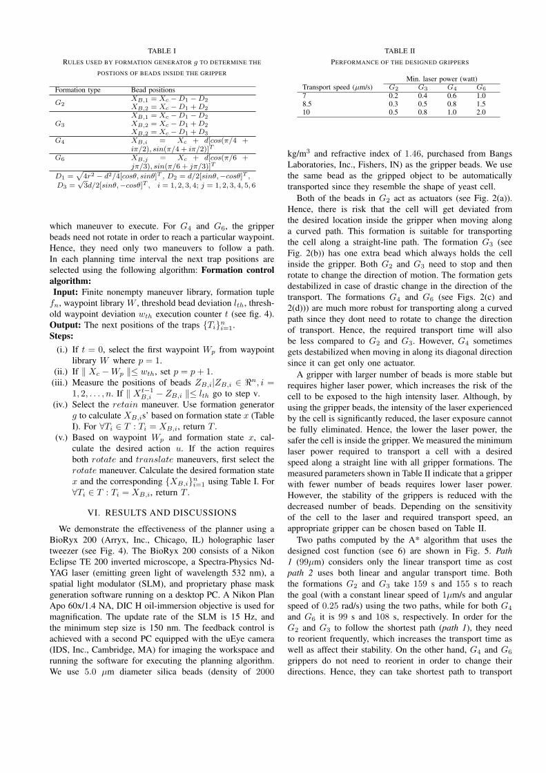
TABLE IRULES USED BY FORMATION GENERATOR g TO DETERMINE THE
POSTIONS OF BEADS INSIDE THE GRIPPER
Formation type Bead positions
G2XB,1 = Xc −D1 −D2
XB,2 = Xc −D1 +D2
G3
XB,1 = Xc −D1 −D2
XB,2 = Xc −D1 +D2
XB,2 = Xc −D1 +D3
G4 XB,i = Xc + d[cos(π/4 +iπ/2), sin(π/4 + iπ/2)]T
G6 XB,j = Xc + d[cos(π/6 +jπ/3), sin(π/6 + jπ/3)]T
D1 =√
4r2 − d2/4[cosθ, sinθ]T , D2 = d/2[sinθ,−cosθ]T ,
D3 =√3d/2[sinθ,−cosθ]T , i = 1, 2, 3, 4; j = 1, 2, 3, 4, 5, 6
which maneuver to execute. For G4 and G6, the gripperbeads need not rotate in order to reach a particular waypoint.Hence, they need only two maneuvers to follow a path.In each planning time interval the next trap positions areselected using the following algorithm: Formation controlalgorithm:Input: Finite nonempty maneuver library, formation tuplefn, waypoint library W , threshold bead deviation lth, thresh-old waypoint deviation wth execution counter t (see fig. 4).Output: The next positions of the traps Tini=1.Steps:
(i.) If t = 0, select the first waypoint Wp from waypointlibrary W where p = 1.
(ii.) If ∥ Xc −Wp ∥≤ wth, set p = p+ 1.(iii.) Measure the positions of beads ZB,i|ZB,i ∈ ℜn, i =
1, 2, . . . , n. If ∥ Xt−1B,i − ZB,i ∥≤ lth go to step v.
(iv.) Select the retain maneuver. Use formation generatorg to calculate XB,is’ based on formation state x (TableI). For ∀Ti ∈ T : Ti = XB,i, return T .
(v.) Based on waypoint Wp and formation state x, cal-culate the desired action u. If the action requiresboth rotate and translate maneuvers, first select therotate maneuver. Calculate the desired formation statex and the corresponding XB,ini=1 using Table I. For∀Ti ∈ T : Ti = XB,i, return T .
VI. RESULTS AND DISCUSSIONS
We demonstrate the effectiveness of the planner using aBioRyx 200 (Arryx, Inc., Chicago, IL) holographic lasertweezer (see Fig. 4). The BioRyx 200 consists of a NikonEclipse TE 200 inverted microscope, a Spectra-Physics Nd-YAG laser (emitting green light of wavelength 532 nm), aspatial light modulator (SLM), and proprietary phase maskgeneration software running on a desktop PC. A Nikon PlanApo 60x/1.4 NA, DIC H oil-immersion objective is used formagnification. The update rate of the SLM is 15 Hz, andthe minimum step size is 150 nm. The feedback control isachieved with a second PC equipped with the uEye camera(IDS, Inc., Cambridge, MA) for imaging the workspace andrunning the software for executing the planning algorithm.We use 5.0 µm diameter silica beads (density of 2000
TABLE IIPERFORMANCE OF THE DESIGNED GRIPPERS
Min. laser power (watt)Transport speed (µm/s) G2 G3 G4 G6
7 0.2 0.4 0.6 1.08.5 0.3 0.5 0.8 1.510 0.5 0.8 1.0 2.0
kg/m3 and refractive index of 1.46, purchased from BangsLaboratories, Inc., Fishers, IN) as the gripper beads. We usethe same bead as the gripped object to be automaticallytransported since they resemble the shape of yeast cell.
Both of the beads in G2 act as actuators (see Fig. 2(a)).Hence, there is risk that the cell will get deviated fromthe desired location inside the gripper when moving alonga curved path. This formation is suitable for transportingthe cell along a straight-line path. The formation G3 (seeFig. 2(b)) has one extra bead which always holds the cellinside the gripper. Both G2 and G3 need to stop and thenrotate to change the direction of motion. The formation getsdestabilized in case of drastic change in the direction of thetransport. The formations G4 and G6 (see Figs. 2(c) and2(d))) are much more robust for transporting along a curvedpath since they dont need to rotate to change the directionof transport. Hence, the required transport time will alsobe less compared to G2 and G3. However, G4 sometimesgets destabilized when moving in along its diagonal directionsince it can get only one actuator.
A gripper with larger number of beads is more stable butrequires higher laser power, which increases the risk of thecell to be exposed to the high intensity laser. Although, byusing the gripper beads, the intensity of the laser experiencedby the cell is significantly reduced, the laser exposure cannotbe fully eliminated. Hence, the lower the laser power, thesafer the cell is inside the gripper. We measured the minimumlaser power required to transport a cell with a desiredspeed along a straight line with all gripper formations. Themeasured parameters shown in Table II indicate that a gripperwith fewer number of beads requires lower laser power.However, the stability of the grippers is reduced with thedecreased number of beads. Depending on the sensitivityof the cell to the laser and required transport speed, anappropriate gripper can be chosen based on Table II.
Two paths computed by the A* algorithm that uses thedesigned cost function (see 6) are shown in Fig. 5. Path1 (99µm) considers only the linear transport time as costpath 2 uses both linear and angular transport time. Boththe formations G2 and G3 take 159 s and 155 s to reachthe goal (with a constant linear speed of 1µm/s and angularspeed of 0.25 rad/s) using the two paths, while for both G4
and G6 it is 99 s and 108 s, respectively. In order for theG2 and G3 to follow the shortest path (path 1), they needto reorient frequently, which increases the transport time aswell as affect their stability. On the other hand, G4 and G6
grippers do not need to reorient in order to change theirdirections. Hence, they can take shortest path to transport
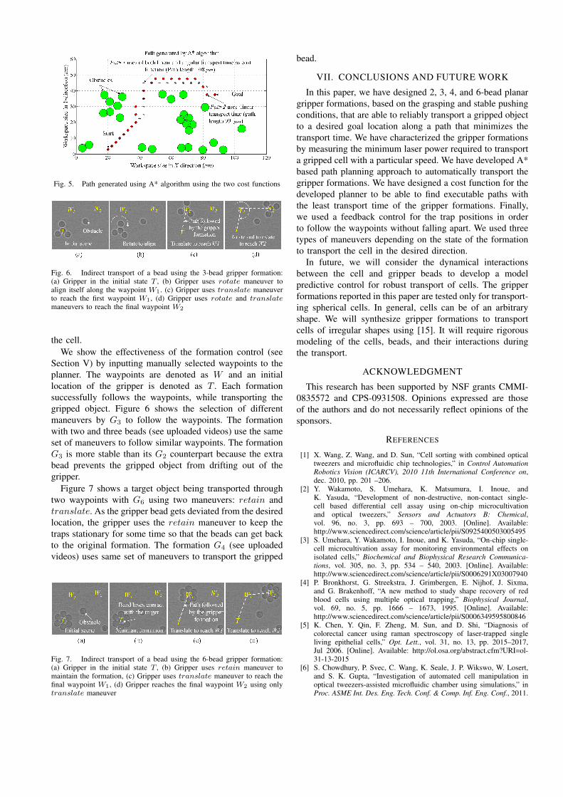
Fig. 5. Path generated using A* algorithm using the two cost functions
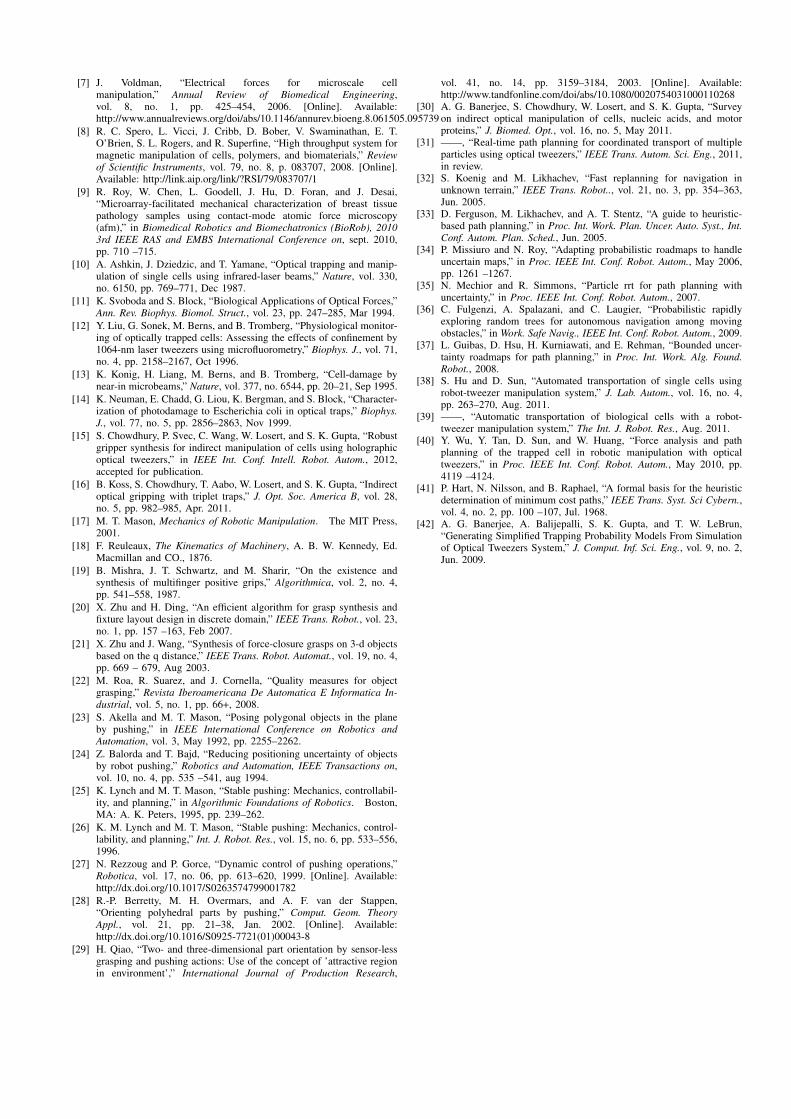
Fig. 6. Indirect transport of a bead using the 3-bead gripper formation:(a) Gripper in the initial state T , (b) Gripper uses rotate maneuver toalign itself along the waypoint W1. (c) Gripper uses translate maneuverto reach the first waypoint W1, (d) Gripper uses rotate and translatemaneuvers to reach the final waypoint W2
the cell.We show the effectiveness of the formation control (see
Section V) by inputting manually selected waypoints to theplanner. The waypoints are denoted as W and an initiallocation of the gripper is denoted as T . Each formationsuccessfully follows the waypoints, while transporting thegripped object. Figure 6 shows the selection of differentmaneuvers by G3 to follow the waypoints. The formationwith two and three beads (see uploaded videos) use the sameset of maneuvers to follow similar waypoints. The formationG3 is more stable than its G2 counterpart because the extrabead prevents the gripped object from drifting out of thegripper.
Figure 7 shows a target object being transported throughtwo waypoints with G6 using two maneuvers: retain andtranslate. As the gripper bead gets deviated from the desiredlocation, the gripper uses the retain maneuver to keep thetraps stationary for some time so that the beads can get backto the original formation. The formation G4 (see uploadedvideos) uses same set of maneuvers to transport the gripped
Fig. 7. Indirect transport of a bead using the 6-bead gripper formation:(a) Gripper in the initial state T , (b) Gripper uses retain maneuver tomaintain the formation, (c) Gripper uses translate maneuver to reach thefinal waypoint W1, (d) Gripper reaches the final waypoint W2 using onlytranslate maneuver
bead.
VII. CONCLUSIONS AND FUTURE WORK
In this paper, we have designed 2, 3, 4, and 6-bead planargripper formations, based on the grasping and stable pushingconditions, that are able to reliably transport a gripped objectto a desired goal location along a path that minimizes thetransport time. We have characterized the gripper formationsby measuring the minimum laser power required to transporta gripped cell with a particular speed. We have developed A*based path planning approach to automatically transport thegripper formations. We have designed a cost function for thedeveloped planner to be able to find executable paths withthe least transport time of the gripper formations. Finally,we used a feedback control for the trap positions in orderto follow the waypoints without falling apart. We used threetypes of maneuvers depending on the state of the formationto transport the cell in the desired direction.
In future, we will consider the dynamical interactionsbetween the cell and gripper beads to develop a modelpredictive control for robust transport of cells. The gripperformations reported in this paper are tested only for transport-ing spherical cells. In general, cells can be of an arbitraryshape. We will synthesize gripper formations to transportcells of irregular shapes using [15]. It will require rigorousmodeling of the cells, beads, and their interactions duringthe transport.
ACKNOWLEDGMENT
This research has been supported by NSF grants CMMI-0835572 and CPS-0931508. Opinions expressed are thoseof the authors and do not necessarily reflect opinions of thesponsors.
REFERENCES
[1] X. Wang, Z. Wang, and D. Sun, “Cell sorting with combined opticaltweezers and microfluidic chip technologies,” in Control AutomationRobotics Vision (ICARCV), 2010 11th International Conference on,dec. 2010, pp. 201 –206.
[2] Y. Wakamoto, S. Umehara, K. Matsumura, I. Inoue, andK. Yasuda, “Development of non-destructive, non-contact single-cell based differential cell assay using on-chip microcultivationand optical tweezers,” Sensors and Actuators B: Chemical,vol. 96, no. 3, pp. 693 – 700, 2003. [Online]. Available:http://www.sciencedirect.com/science/article/pii/S0925400503005495
[3] S. Umehara, Y. Wakamoto, I. Inoue, and K. Yasuda, “On-chip single-cell microcultivation assay for monitoring environmental effects onisolated cells,” Biochemical and Biophysical Research Communica-tions, vol. 305, no. 3, pp. 534 – 540, 2003. [Online]. Available:http://www.sciencedirect.com/science/article/pii/S0006291X03007940
[4] P. Bronkhorst, G. Streekstra, J. Grimbergen, E. Nijhof, J. Sixma,and G. Brakenhoff, “A new method to study shape recovery of redblood cells using multiple optical trapping,” Biophysical Journal,vol. 69, no. 5, pp. 1666 – 1673, 1995. [Online]. Available:http://www.sciencedirect.com/science/article/pii/S0006349595800846
[5] K. Chen, Y. Qin, F. Zheng, M. Sun, and D. Shi, “Diagnosis ofcolorectal cancer using raman spectroscopy of laser-trapped singleliving epithelial cells,” Opt. Lett., vol. 31, no. 13, pp. 2015–2017,Jul 2006. [Online]. Available: http://ol.osa.org/abstract.cfm?URI=ol-31-13-2015
[6] S. Chowdhury, P. Svec, C. Wang, K. Seale, J. P. Wikswo, W. Losert,and S. K. Gupta, “Investigation of automated cell manipulation inoptical tweezers-assisted microfluidic chamber using simulations,” inProc. ASME Int. Des. Eng. Tech. Conf. & Comp. Inf. Eng. Conf., 2011.
[7] J. Voldman, “Electrical forces for microscale cellmanipulation,” Annual Review of Biomedical Engineering,vol. 8, no. 1, pp. 425–454, 2006. [Online]. Available:http://www.annualreviews.org/doi/abs/10.1146/annurev.bioeng.8.061505.095739
[8] R. C. Spero, L. Vicci, J. Cribb, D. Bober, V. Swaminathan, E. T.O’Brien, S. L. Rogers, and R. Superfine, “High throughput system formagnetic manipulation of cells, polymers, and biomaterials,” Reviewof Scientific Instruments, vol. 79, no. 8, p. 083707, 2008. [Online].Available: http://link.aip.org/link/?RSI/79/083707/1
[9] R. Roy, W. Chen, L. Goodell, J. Hu, D. Foran, and J. Desai,“Microarray-facilitated mechanical characterization of breast tissuepathology samples using contact-mode atomic force microscopy(afm),” in Biomedical Robotics and Biomechatronics (BioRob), 20103rd IEEE RAS and EMBS International Conference on, sept. 2010,pp. 710 –715.
[10] A. Ashkin, J. Dziedzic, and T. Yamane, “Optical trapping and manip-ulation of single cells using infrared-laser beams,” Nature, vol. 330,no. 6150, pp. 769–771, Dec 1987.
[11] K. Svoboda and S. Block, “Biological Applications of Optical Forces,”Ann. Rev. Biophys. Biomol. Struct., vol. 23, pp. 247–285, Mar 1994.
[12] Y. Liu, G. Sonek, M. Berns, and B. Tromberg, “Physiological monitor-ing of optically trapped cells: Assessing the effects of confinement by1064-nm laser tweezers using microfluorometry,” Biophys. J., vol. 71,no. 4, pp. 2158–2167, Oct 1996.
[13] K. Konig, H. Liang, M. Berns, and B. Tromberg, “Cell-damage bynear-in microbeams,” Nature, vol. 377, no. 6544, pp. 20–21, Sep 1995.
[14] K. Neuman, E. Chadd, G. Liou, K. Bergman, and S. Block, “Character-ization of photodamage to Escherichia coli in optical traps,” Biophys.J., vol. 77, no. 5, pp. 2856–2863, Nov 1999.
[15] S. Chowdhury, P. Svec, C. Wang, W. Losert, and S. K. Gupta, “Robustgripper synthesis for indirect manipulation of cells using holographicoptical tweezers,” in IEEE Int. Conf. Intell. Robot. Autom., 2012,accepted for publication.
[16] B. Koss, S. Chowdhury, T. Aabo, W. Losert, and S. K. Gupta, “Indirectoptical gripping with triplet traps,” J. Opt. Soc. America B, vol. 28,no. 5, pp. 982–985, Apr. 2011.
[17] M. T. Mason, Mechanics of Robotic Manipulation. The MIT Press,2001.
[18] F. Reuleaux, The Kinematics of Machinery, A. B. W. Kennedy, Ed.Macmillan and CO., 1876.
[19] B. Mishra, J. T. Schwartz, and M. Sharir, “On the existence andsynthesis of multifinger positive grips,” Algorithmica, vol. 2, no. 4,pp. 541–558, 1987.
[20] X. Zhu and H. Ding, “An efficient algorithm for grasp synthesis andfixture layout design in discrete domain,” IEEE Trans. Robot., vol. 23,no. 1, pp. 157 –163, Feb 2007.
[21] X. Zhu and J. Wang, “Synthesis of force-closure grasps on 3-d objectsbased on the q distance,” IEEE Trans. Robot. Automat., vol. 19, no. 4,pp. 669 – 679, Aug 2003.
[22] M. Roa, R. Suarez, and J. Cornella, “Quality measures for objectgrasping,” Revista Iberoamericana De Automatica E Informatica In-dustrial, vol. 5, no. 1, pp. 66+, 2008.
[23] S. Akella and M. T. Mason, “Posing polygonal objects in the planeby pushing,” in IEEE International Conference on Robotics andAutomation, vol. 3, May 1992, pp. 2255–2262.
[24] Z. Balorda and T. Bajd, “Reducing positioning uncertainty of objectsby robot pushing,” Robotics and Automation, IEEE Transactions on,vol. 10, no. 4, pp. 535 –541, aug 1994.
[25] K. Lynch and M. T. Mason, “Stable pushing: Mechanics, controllabil-ity, and planning,” in Algorithmic Foundations of Robotics. Boston,MA: A. K. Peters, 1995, pp. 239–262.
[26] K. M. Lynch and M. T. Mason, “Stable pushing: Mechanics, control-lability, and planning,” Int. J. Robot. Res., vol. 15, no. 6, pp. 533–556,1996.
[27] N. Rezzoug and P. Gorce, “Dynamic control of pushing operations,”Robotica, vol. 17, no. 06, pp. 613–620, 1999. [Online]. Available:http://dx.doi.org/10.1017/S0263574799001782
[28] R.-P. Berretty, M. H. Overmars, and A. F. van der Stappen,“Orienting polyhedral parts by pushing,” Comput. Geom. TheoryAppl., vol. 21, pp. 21–38, Jan. 2002. [Online]. Available:http://dx.doi.org/10.1016/S0925-7721(01)00043-8
[29] H. Qiao, “Two- and three-dimensional part orientation by sensor-lessgrasping and pushing actions: Use of the concept of ’attractive regionin environment’,” International Journal of Production Research,
vol. 41, no. 14, pp. 3159–3184, 2003. [Online]. Available:http://www.tandfonline.com/doi/abs/10.1080/0020754031000110268
[30] A. G. Banerjee, S. Chowdhury, W. Losert, and S. K. Gupta, “Surveyon indirect optical manipulation of cells, nucleic acids, and motorproteins,” J. Biomed. Opt., vol. 16, no. 5, May 2011.
[31] ——, “Real-time path planning for coordinated transport of multipleparticles using optical tweezers,” IEEE Trans. Autom. Sci. Eng., 2011,in review.
[32] S. Koenig and M. Likhachev, “Fast replanning for navigation inunknown terrain,” IEEE Trans. Robot.., vol. 21, no. 3, pp. 354–363,Jun. 2005.
[33] D. Ferguson, M. Likhachev, and A. T. Stentz, “A guide to heuristic-based path planning,” in Proc. Int. Work. Plan. Uncer. Auto. Syst., Int.Conf. Autom. Plan. Sched., Jun. 2005.
[34] P. Missiuro and N. Roy, “Adapting probabilistic roadmaps to handleuncertain maps,” in Proc. IEEE Int. Conf. Robot. Autom., May 2006,pp. 1261 –1267.
[35] N. Mechior and R. Simmons, “Particle rrt for path planning withuncertainty,” in Proc. IEEE Int. Conf. Robot. Autom., 2007.
[36] C. Fulgenzi, A. Spalazani, and C. Laugier, “Probabilistic rapidlyexploring random trees for autonomous navigation among movingobstacles,” in Work. Safe Navig., IEEE Int. Conf. Robot. Autom., 2009.
[37] L. Guibas, D. Hsu, H. Kurniawati, and E. Rehman, “Bounded uncer-tainty roadmaps for path planning,” in Proc. Int. Work. Alg. Found.Robot., 2008.
[38] S. Hu and D. Sun, “Automated transportation of single cells usingrobot-tweezer manipulation system,” J. Lab. Autom., vol. 16, no. 4,pp. 263–270, Aug. 2011.
[39] ——, “Automatic transportation of biological cells with a robot-tweezer manipulation system,” The Int. J. Robot. Res., Aug. 2011.
[40] Y. Wu, Y. Tan, D. Sun, and W. Huang, “Force analysis and pathplanning of the trapped cell in robotic manipulation with opticaltweezers,” in Proc. IEEE Int. Conf. Robot. Autom., May 2010, pp.4119 –4124.
[41] P. Hart, N. Nilsson, and B. Raphael, “A formal basis for the heuristicdetermination of minimum cost paths,” IEEE Trans. Syst. Sci Cybern.,vol. 4, no. 2, pp. 100 –107, Jul. 1968.
[42] A. G. Banerjee, A. Balijepalli, S. K. Gupta, and T. W. LeBrun,“Generating Simplified Trapping Probability Models From Simulationof Optical Tweezers System,” J. Comput. Inf. Sci. Eng., vol. 9, no. 2,Jun. 2009.