Automated Flight Strip Management System Functional Description
46
Project Report ATC-174 Automated Flight Strip Management System Functional Description S. D. Thompson 19 November 1990 Lincoln Laboratory MASSACHUSETTS INSTITUTE OF TECHNOLOGY LEXINGTON, MASSACHUSETTS Prepared for the Federal Aviation Administration, Washington, D.C. 20591 This document is available to the public through the National Technical Information Service, Springfield, VA 22161
Transcript of Automated Flight Strip Management System Functional Description
Project ReportATC-174
Automated Flight Strip Management System
Functional Description
S. D. Thompson
19 November 1990
Lincoln Laboratory MASSACHUSETTS INSTITUTE OF TECHNOLOGY
LEXINGTON, MASSACHUSETTS
Prepared for the Federal Aviation Administration, Washington, D.C. 20591
This document is available to the public through
the National Technical Information Service, Springfield, VA 22161

This document is disseminated under the sponsorship of the Department of Transportation in the interest of information exchange. The United States Government assumes no liability for its contents or use thereof.

1. Report No.
ATC-li4
2. Government Accession No.
DOT/FAAJARD-90/2i
TECHNICAL REPORT STANDARD TITLE PAGE
3. Recipient's Catalog No.
4. Title and Subtitle
Automatl'd Flight Strip Managl'ml'nt Systl'm Functional Description
7. Author(s)
Stl'vl'n D. Thompson
9. Performing Organization Name and Address
Linroln Laboratory, MITP.O. Box 73Lt'xington. MA 02] 73-9]08
12. Sponsoring Agency Name and AddressDl'partml'nt of TransportationFederal Aviation AdministrationSystems Rt'st'arrh and Dl'vl'lopment Sl'rvirt'Washington. DC 20591
15. Supplementary Notes
5. Report Date19 Novemher ]990
6. Performing Organization Code
8. Performing Organization Report No.
ATC-li4
10. Work Unit No. (TRAIS)
11. Contract or Grant No.
DTFA-O I -89-Z02039
13. Type of Report and Period Covered
Project Rt'port
14. Sponsoring Agency Code
This report is hased on studit's pt'rforml'd at Lincoln Lahoratory. a center for research operated hyMassachusetts Institutl' of Technology umll'r Air Forcl' Contract FI9628-90-C-0002
16. Abstract
This documt'nt givl's a high ll'wl funrtional ovt'rvil'w of an automated flight strip management system.Thl' current manual flight strip system at Boston's Logan Airport is reviewed amI described in detail forhoth thl' Towl'r Cah and TRACON with emphasis on thl' information flow as an aircraft progresses throughthe system. The intl'rfacl's bl'tween thl' ATC elements, as they relatl' to flight data, are explained. Finally.the systl'm rl'quirl'ml'nts arl' descrilwd including spl'cific rl'quirements for Tower Cab positions.
17. Key Words
flight progrl'SS stripsair traffic control
automation
18. Distribution Statement
Document is available to the public through thl'National Technical Information Service,Springfield, VA 22]61.
19. Security Classif. (of this report)
Unclassifil'd
FORM DOT F 1700.7 (8-72)
20. Security Classif. (of this page)
Unclassifil'd
Reproduction of completed page authorized
21. No. of Pages
50
22. Price
ACKNOWLEDGMENT
The author would like to acknowledge the assistance of the staff of the BostonTower in the preparation of this report In addition, concepts for the Automated StripManagement System are largely based on ideas originated by Boston Tower personnel.
ill
TABLE OF CONTENTS
Acknowledgement ill
List of Dlustrations vuList of Tables vu
1. INTRODUcnON 1
2. PROORAM DESCRIPTION 3
3. FUNcnONAL OVERVIEW 5
3.1 Flight Plan Data Base 53.2 Interfaces 53.3 Human Factors 53.4 Operational Recording and Eligibility Functions 63.5 Traffic Data 6
3.6 Archiving and Retrieval 63.7 Hardware 6
4. CURRENT BOSTON FLIGHT STRIP SYSTEM 7
4.1 Flight Plans in the ATC System 74.2 Flight Progress Strip Description 104.3 Use of Flight Progress Strips at Boston 16
4.3.1 Use of Flight Progress Strips in the Logan Tower Cab 164.3.2 Use of Flight Progress Strips in Boston TRACON 16
4.4 Flight Stages and the Processing of Flight Progress Strips 184.4.1 Departing 18
4.4.1.1 Aircraft at Gate without Clearance 184.4.1.2 Clearance Delivery 214.4.1.3 Boston "Gate" 224.4.1.4 Taxiing 234.4.1.5 Take-Off 234.4.1.6 Handoff to TRACON 24
4.4.2 Arriving 244.4.2.1 In Boston TRACON airspace 244.4.2.2 Local Handoff 244.4.2.3 Ground Control Handoff 264.4.2.4 Out-of-Movement Area 26
5. SYSTEM REQUIREMENTS 27
5.1 Hardware and Interface Requirements 275.2. Screen Design Requirements 30
5.2.1 Supervisor 305.2.2 Flight Data 315.2.3 Clearance Delivery 33
v
T ABLE OF CONTENTS (Continued)
5.2.4 Boston Gate5.2.5 Ground Control5.2.6 Local Control (Tower)5.2.7 HelicopterfI'CA5.2.8 TRACON
5.3 Human Factors Requirements5.4 Data Base Requirements
5.4.1 Archival and Retrieval Requirements5.4.2 Traffic Data Recording Requirements5.4.3 Operational Recording and Eligibility Requirements
5.5 Optimum Queue Module
VI
3336383838384040414141
LIST OF ILLUSTRATIONS
FigureNo. Page
1 FAA Flight Plan Fonn 62 ATC Flight Plan Flow 73 lllustration of Terminal Flight Progress Strip 94 Use of Flight Progress Strips in Boston Logan Airport 155 Figure Progress Strip Flow for Departure Aircraft at
Boston Logan Airport 176 Flight Progress Strip Flow for Arrival Aircraft at
Boston Logan Airport 237 Current Interfaces for Flight Data Infonnation Flow for
Flights into or out of Boston 268 ASMS Interface Requirements 279a ASMS Flight Data Screen 309b ASMS Oearance Delivery Screen 329c ASMS Boston Gate Screen 339d ASMS Ground Control Screen 35ge ASMS LocaV TRACON Screen 37
LIST OF TABLES
TableNo.
1234
Terminal Flight Progress Strip DataAircraft Equipment SuffIx in Data Blocks 3Flight Progress Strip Clearance AbbreviationsFlight Progress Strip Miscellaneous Abbreviations
Vll
Page
10111213
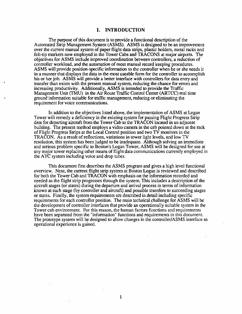
1. INTRODUCTION
The purpose of this document is to provide a functional description of theAutomated Strip Management System (ASMS). ASMS is designed to be an improvementover the current manual system of paper flight data strips, plastic holders, metal racks andfelt-tip markers now employed in the Tower Cabs and TRACONS at major airports. Theobjectives for ASMS include improved coordination between controllers, a reduction ofcontroller workload, and the automation of most manual record keeping procedures.ASMS will provide position-specific information to the controller when he or she needs itin a manner that displays the data in the most useable fonn for the controller to accomplishhis or her job. ASMS will provide a better interface with controllers for data entry andtransfer than exists with the present manual system, reducing the chance for errors andincreasing productivity. Additionally, ASMS is intended to provide the TrafficManagement Unit (TMU) in the Air Route Traffic Control Center (ARTCC) real timeground information suitable for traffic management, reducing or eliminating therequirement for voice communications.
In addition to the objectives listed above, the implementation of ASMS at LoganTower will remedy a deficiency in the existing system for passing Flight Progress Stripdata for departing aircraft from the Tower Cab to the TRACON located in an adjacentbuilding. The present method employs a video camera in the cab pointed down at the rackof Flight Progress Strips at the Local Control position and two TV monitors in theTRACON. As a result of reflections, variations in tower light levels, and low TVresolution, this system has been judged to be inadequate. Although solving an immediateand serious problem specific to Boston's Logan Tower, ASMS will be designed for use atany major tower replacing other means of flight data communications currently employed inthe ATC system including voice and drop tubes.
This document first describes the ASMS program and gives a high level functionaloverview. Next, the current flight strip system.at Boston Logan is reviewed and describedfor both the Tower Cab and TRACON with emphasis on the information recorded andneeded as the flight strip progresses through the system. This includes a description of theaircraft stages (or states) during the departure and arrival process in terms of informationknown at each stage (by controller and aircraft) and possible transfers to succeeding stagesor states. Finally, the system requirements are described in detail including specificrequirements for each controller position. The main technical challenge for ASMS will bethe development of controller interfaces that provide an operationally suitable system in theTower cab environment. For this reason, the human factors functions and requirementshave been separated from the "information" functions and requirements in this document.The prototype system will be designed to allow changes in the controller/ASMS interface asoperational experience is gained.
1
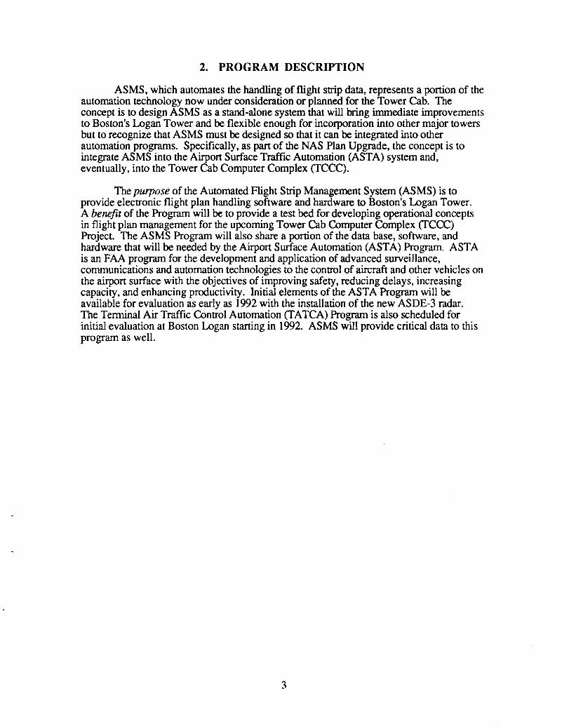
2. PROGRAM DESCRIPTION
ASMS, which automates the handling of flight strip data, represents a portion of theautomation technology now under consideration or planned for the Tower Cab. Theconcept is to design ASMS as a stand-alone system that will bring immediate improvementsto Boston's Logan Tower and be flexible enough for incorporation into other major towersbut to recognize that ASMS must be designed so that it can be integrated into otherautomation programs. Specifically, as part of the NAS Plan Upgrade, the concept is tointegrate ASMS into the Airport Surface Traffic Automation (ASTA) system and,eventually, into the Tower Cab Computer Complex (TCCC).
The purpose of the Automated Flight Strip Management System (ASMS) is toprovide electronic flight plan handling software and hardware to Boston's Logan Tower.A benefit of the Program will be to provide a test bed for developing operational conceptsin flight plan management for the upcoming Tower Cab Computer Complex (TCCC)Project. The ASMS Program will also share a portion of the data base, software, andhardware that will be needed by the Airport Surface Automation (ASTA) Program. ASTAis an FAA program for the development and application of advanced surveillance,communications and automation technologies to the control of aircraft and other vehicles onthe airport surface with the objectives of improving safety, reducing delays, increasingcapacity, and enhancing productivity. Initial elements of the ASTA Program will beavailable for evaluation as early as 1992 with the installation of the new ASDE-3 radar.The Terminal Air Traffic Control Automation (TATCA) Program is also scheduled forinitial evaluation at Boston Logan starting in 1992. ASMS will provide critical data to thisprogram as well.
3
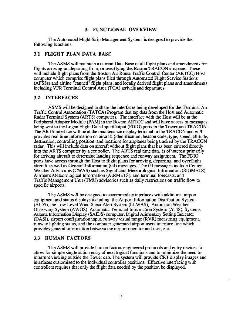
3. FUNCTIONAL OVERVIEW
The Automated Flight Strip Management System is designed to provide thefollowing functions:
3.1 FLIGHT PLAN DATA BASE
The ASMS will maintain a current Data Base of all flight plans and amendments forflights arriving in, departing from, or overflying the Boston TRACON airspace. Thesewill include flight plans from the Boston Air Route Traffic Control Center (ARTCC) Hostcomputer which comprise flight plans fIled through Automated Flight Service Stations(AFSSs) and airline "canned" flight plans, and locally derived flight plans and amendmentsincluding VFR Terminal Control Area (TCA) arrivals and departures.
3.2 INTERFACES
ASMS will be designed to share the interfaces being developed for the Terminal AirTraffic Control Automation (TATCA) Program that tap data from the Host and AutomaticRadar Terminal System (ARTS) computers. The interface with the Host will be at thePeripheral Adapter Module (PAM) in the Boston ARTCC and will have access to messagesbeing sent to the Logan Flight Data Input/Output (FOIO) ports in the Tower and TRACON.The ARTS interface will be at the maintenance display terminal in the TRACON and willprovides real time information on aircraft (identification, beacon code, type, speed, altitude,destination, controlling position, and location) for airplanes being tracked by the TRACONradar. This will include data on aircraft without flight plans that has been entered directlyinto the ARTS computer by a controller. The ARTS real time data is of interest primarilyfor arriving aircraft to determine landing sequence and runway assignment. The FOIOports have access through the Host to flight plans for arriving, departing, and overflightaircraft as well as General Information (GI) messages. The GI messages include CenterWeather Advisories (CWAS) such as Significant Meteorological Information (SIGMETS),Airman's Meteorological Information (AIRMETS), and terminal forecasts, andTraffic Management Unit (TMU) advisories such as daily restrictions on traffic flow tospecific airports.
The ASMS will be designed to accommodate interfaces with additional airportequipment and status displays including the Airport Information Distribution System(AIDS), the Low Level Wind Shear Alert System (LLWAS), Automatic WeatherObserving System (AWOS), Automatic Terminal Information System (ATIS), SystemsAtlanta Information Display (SAIDS) computer, Digital Alimentary Setting Indicator(DASI), airport configuration input, runway visual range (RVR) measuring equipment,runway lighting status, and the computer generated airport users interface line whichprovides general information between the airport operator and user, etc.
3.3 HUMAN FACTORS
The ASMS will provide human factors engineered protocols and entry devices toallow for simple single action entry of next logical functions and to minimize the need tointerrupt viewing outside the Tower cab. The system will provide CRT display images andinterfaces customized to the individual controller positions. Effective interfacing withcontrollers requires that only the flight data needed by the position be displayed.
5
3.4 OPERATIONAL RECORDING AND ELIGIBILITY FUNCTIONS
The ASMS will provide for a method of recording the time that individualcontrollers spend at each position and automate the controller eligibility checking for eachposition. It will also provide a record of controller training at a position.
3.5 TRAFFIC DATA
The ASMS will provide a means for recording traffic data including Traffic Count,Delay Reporting Data, runway usage and airport configuration, missed approaches, anddelay times by examining real time data. The system will provide for standardized reports.
3.6 ARCHIVING AND RETRIEVAL
The ASMS will provide for a system of archiving and retrieving of all data for aspecified length of time. Long term storage will be provided by off-line devices buttheASMS will have the capability of reading data stored off-line. This will include the abilityto retrieve or recreate displays that were presented to controllers at specified times andinputs by controllers. The most likely system will employ a removable hard disk systemfor economical long term storage and quick access.
3.7 HARDWARE
The ASMS will provide human engineered CRT terminal screens for each controllerposition interconnected with a local area network within the Tower cab and includeintrafacility communications connections with the TRACON. The CRT screens must bereadily visible in high ambient lighting conditions. Specifications for Tower Cab CRTsunder the TCCC contract cannot be met with current color display technology.
--'"
6

4. CURRENT BOSTON FLIGHT STRIP SYSTEM
This section describes the current flight strip system at Boston's Logan Airport.First is a general discussion of how flight plans are entered into the Air Traffic Control(ATC) system and how and where the resulting Flight Progress Strips are generated.Next, the physical handling and processing of the strips is described for the Boston TowerCab and the TRACON environments. Next is a description of the Flight Progress Stripitself and the data contained on the strip. Finally, the progress of a strip is followed inrelation to the progress of an aircraft through the various stages of departure and arrivalwith emphasis on the information available to and input by the various controller positions.This will set the stage for specifying an automated system ensuring that the correctinformation is available to the needed controller position at the right time.
4.1 FLIGHT PLANS IN THE ATe SYSTEM
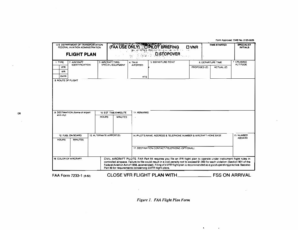
Flight plans for flights conducted under Instrument Flight Rules (lFR) or VisualFlight Rules (VFR) are nominally entered into the Air Traffic Control (ATC) systemthrough Automated Flight Service Stations (AFSS). The pilot calls or visits the AFSS,receives a weather briefing, and files a flight plan with the specialist. A flight plan form isused by the pilots and AFSS specialists to record the information and is reproduced inFigure 1.
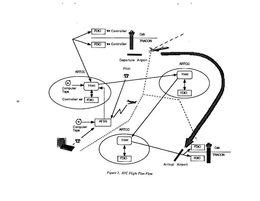
For flights that are conducted repeatedly, such as scheduled airline flights, the flightplan data can be stored on computer tape for automatic entry into the system. Computertapes for airline flight plans are kept at Air Route Traffic Control Centers (ARTCC) andentered directly into the Host computer. The AFSSs also have the capability of storingflight plans on computer tape and this is often done for standard flight plans used, forexample, by air taxis. Flight plans for all IFR flights and any VFR flights that requestservices from ATC, such as traffic advisories, are entered into the Host computer at theARTCC serving the departure airport. The system of Host computer determines whatARTCCs will be controlling the flight and will transmit the flight plan data to thesucceeding controlling ARTCC as the flight progresses. These Host computer generatesFlight Progress Strips through Flight Data Input/Output (FOIO) printers at controllingfacilities. Controllers can also use the FDIO to manually input flight plans. VFR flightsnot requesting services are not entered into the Host computer. The flight plan process isillustrated in Figure 2.
Any flight plan filed at any AFSS or entered from computer tape or manually at anyCenter that enters into the system of Host computers, as described above, for a flight thatwill depart, arrive or fly through airspace controlled by Boston Center, will be transferredto the Host computer at Boston ARTCC in Nashua, New Hampshire. The Host computerat Nashua will determine which of these flights will use airspace controlled by BostonTRACON. The airspace controlled by Boston TRACON is defmed in a letter of agreementbetween Boston TRACON and Boston Center and generally includes airspace within
7
Form Approved: OMB No. 2120-0026
u.s. DEPARTMENT OF TRANSPORTATION(~AA"§i6Nt\f)::~;,L .. :i3'R1E~iNG tJVNR
TIME STARTED SPECIALISTFEDERAL AVIATION ADMINISTRATION INITIALS
.. ..·i~~~.~S~~~~:!~.'~6:S!b~bVEA-'I"
FLIGHT PLAN
1 TYPE 2. AIRCRAFT 3. AIRCRAFT TYPE/ 4 TRUE 5 DEPARTURE POINT 6 DEPARTURE TIME 7 CRUISINGIDENTIFICATION SPECIAL EOUIPMENT AIRSPEED ALTITUDE
VFR PROPOSED (Z) ACTUAL (Z)
IFR
DVFR KTS
8 ROUTE OF FLIGHT
9 DESTINATION (Name 01 airport 10 EST TIME ENROUTE 1,. REMARKSandelly)
HOURS MINUTES
12. FUEL ON BOARD 13 ALTERNATE AIRPORT(S) 14. PILors NAME. ADDRESS &TELEPHONE NUMBER & AIRCRAFT HOME BASE 15 NUMBER
HOURS MINUTESABOARD
17. DESTINATION CONTACTfTELEPHONE (OPTIONAL)
16 COLOR OF AIRCRAFT CIVIL AIRCRAFT PILOTS. FAR Part 91 requires you file an IFR flight plan to operate under instrument flight rules incontrolled airspace. Failure to file could result in a civil penalty not to exceed $1.000 for each violation (Section 901 of theFederal Aviation Act of 1958. as amended). Filing of a VFR flight plan is recommended as a good operating practice. See alsoPart 99 for requirements concerning DVFA flight plans.
FAA Form 7233-1 (8-82) CLOSE VFR FLIGHT PLAN WITH _
Figure 1. FAA Flight Plan Form
FSS ON ARRIVAL
ARTCC
Pilot
Departure
1'9 Controller." Cab ./ ./
1'--FD-o-I'" Controller II---TRACON--~-~-</-,-- "--11IIIIIIII-.,,
Airport,,,,,,,
ComputerTape
,,.~.. ......
comp
7uter •••• ARTCC
Tape •••.'
• ,"B' ••••••••••••.... ..'
Figure 2. ATe Flight Plan Flow

approximately thirty miles of Logan airport up to approximately fourteen thousand feet plussome lower "shelves" incorporating satellite airports and transition airspace. At apredetennined adjustable time (usually thirty minutes) before departure, a Flight ProgressStrip is sent to the Boston Tower and either printed in the Tower cab or TRACON. Flightstrips for aircraft departing from Logan are printed on the FDIO printer in the Tower Cab.Flight strips for aircraft departing from satellite airports or overflights within BostonTRACON boundaries are printed in the TRACON. Flight progress information for aircraftarriving at Logan or satellite airports is also available from the Boston ARTCC Hostcomputer but, as described below, is not always printed in the form of a Flight ProgressStrip.
Data for VFR aircraft that me a flight plan and request ATC radar services are alsoavailable in the Host computer. Flight data for VFR aircraft arriving and departing fromLogan or transiting the Boston Tenninal Control Area (TCA) that have not filed a flightplan is input into the ARTS computer by a controller but no Flight Progress Strip isgenerated and the data is not received by the Host computer. The Flight Data position inBoston Tower will insert the flight information into the ARTS for a VFR flight departingLogan. This data includes the aircraft identification, aircraft type, requested altitude,direction of flight, and a single letter designation code indicating the departure controlsector that will handle the flight initially. For VFR arrivals, the data is entered by theapproach control position that first works the aircraft and gives the clearance into the TCA.The data includes the aircraft identification and type but will not generally include thealtitude since it appears on the Mode C readout in the data tag. The destination airport isincluded and will appear on the data tag.
4.2 FLIGHT PROGRESS STRIP DESCRIPTION
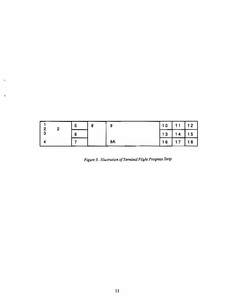
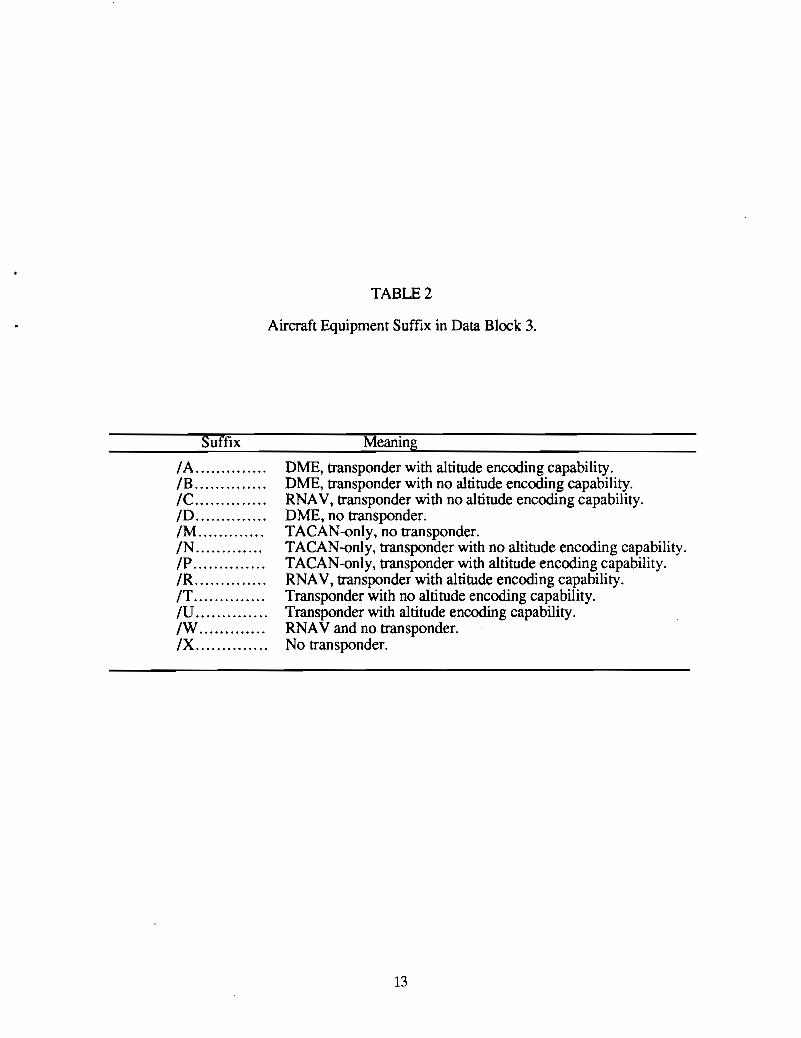
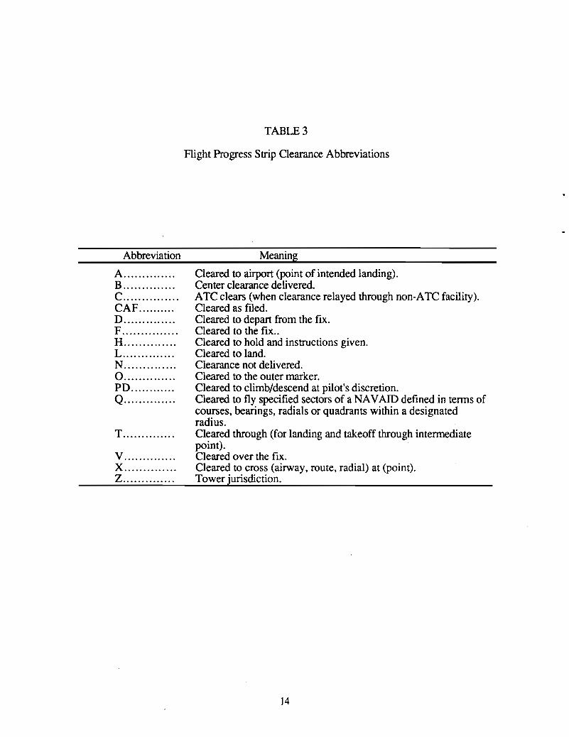
The Flight Progress Strip, depicted in Figure 3, differs slightly from the FlightProgress Strips used by En Route Centers although the differences are not important andASMS is concerned with terminal Flight Progress Strips. The strip of paper isapproximately 8 inches long by 1 inch wide with perforations on the long edges so that thestrips can be separated after being printed on the FDIO printer. There are plastic holdersavailable in the TRACON and Tower that are sized to hold the strip and fit into a verticalrack to facilitate reordering of the strips. The data that appears on a Flight Progress Stripdepends on whether it is for an arrival, departure, or overflight. The numbers on the stripin Figure 3 are called data blocks. Table 1 lists the data recorded in the data blocks depictedon the strip for the three categories of aircraft. Table 2 is a list of the aircraft equipmentsuffix codes used in block 3 appearing after the designation for the type of aircraft.Tables 3 and 4 list clearance and miscellaneous abbreviations approved for use bycontrollers.
10
1 5 8 9 1 0 1 1 1 22 23 6 1 3 1 4 15
4 7 9A 1 6 17 1 8
Figure 3. Illustration o/Terminal Flight Progress Strip
11
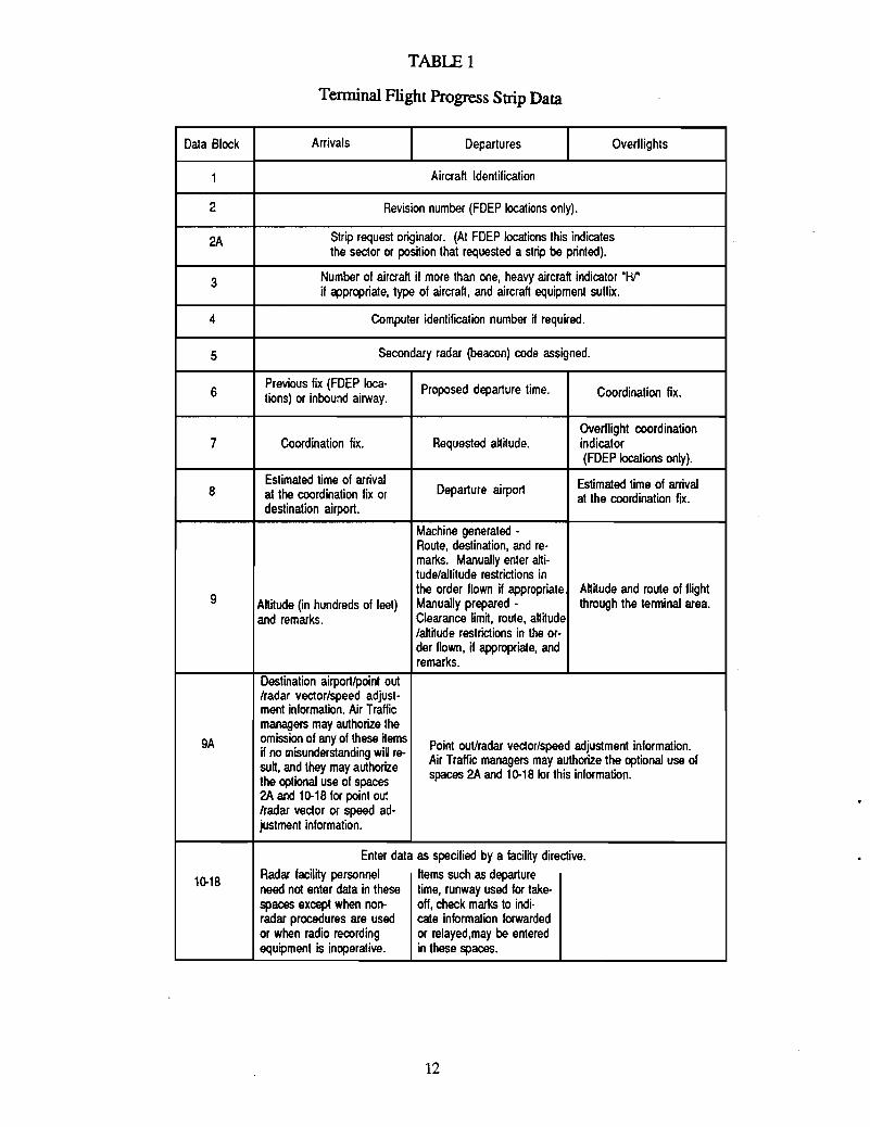
TABLE 1
Terminal Flight Progress Strip Data
Data Block Arrivals Departures Overflights
1 Aircraft Identification
2 Revision number (FDEP locations only).
2A Strip request originator. (At FDEP locations this indicatesthe sector or pos~ion that requested a strip be printed).
3 Number of aircraft if more than one, heavy aircraft indicator "HI"if appropriate, type of aircraft, and aircraft equipment sullix.
4 Computer identification number nrequired.
5 Secondary radar (beacon) code assigned.
6Previous fix (FDEP Ioca- Proposed departure time. Coordination fix.tions) or inbound airway.
Overflight coordination7 Coordination fix. Requested att~ude. indicator
(FDEP locations only).
Estimated time of arrivalDeparture airport Estimated time of arrival8 at the coordination fix or at the coordination fix.
destination airport.
Machine generated -Route, destination, and re-marks. Manually enter alti-tude/altitude restrictions in
9the order flown if appropriate Att~ude and route of flight
Att~ude (in hundreds of feet) Manually prepared - through the terminal area.and remarks. Clearance lim~, route, att~ude
/aIt~ude restrictions in the or-der flown, if appropriate, andremarks.
Destination airport/point out/radar vector/speed adjust-ment information. Air Trallicmanagers may authorize the
9A omission of any of these hems Point out/radar vedor/speed adjustment information.if no misunderstanding will re-sutt, and they may authorize Air Traffic managers may authorize the optional use of
the optional use of spaces spaces 2A and 10-18 lor this information.
2A and 10-18 for point out/radar vector or speed ad-justment information.
Enter data as specified by a lacil~y directive.
10-18 Radar facil~y personnel Items such as departureneed not enter data in these time, runway used for take-spaces except when non- olf, check marks to indi-radar procedures are used cate inlormation forwardedor when radio recording or relayed,may be enteredequipment is inoperative. in these spaces.
12
SuffIx
TABLE 2
Aircraft Equipment SuffIx in Data Block 3.
Meaning
IA .lB .IC .ID .1M .IN .IP .IR .IT .IV .IW .IX .
DME, transponder with altitude encoding capability.DME, transponder with no altitude encoding capability.RNAV, transponder with no altitude encoding capability.DME, no transponder.TACAN-only, no transponder.TACAN-only, transponder with no altitude encoding capability.TACAN-only, transponder with altitude encoding capability.RNAV, transponder with altitude encoding capability.Transponder with no altitude encoding capability.Transponder with altitude encoding capability.RNAV and no transponder.No transponder.
13
Abbreviation
A .B .C .CAF .D ..F .H .L ..N ..0 .PO .Q .
T .
v ..X .Z .
TABLE 3
Flight Progress Strip Clearance Abbreviations
Meaning
Cleared to airport (point of intended landing).Center clearance delivered.ATC clears (when clearance relayed through non-ATC facility).Cleared as filed.Cleared to depart from the fix.Cleared to the fix..Cleared to hold and instructions given.Cleared to land.Clearance not delivered.Cleared to the outer marker.Cleared to climb/descend at pilot's discretion.Cleared to fly specified sectors of a NAVAID defined in termS ofcourses, bearings, radials or quadrants within a designatedradius.Cleared through (for landing and takeoff through intermediatepoint).Cleared over the fix.Cleared to cross (airway, route, radial) at (point).Tower jurisdiction.
14
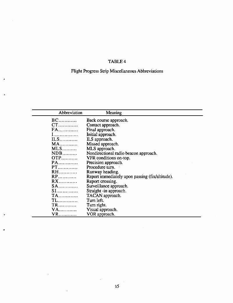
TABLE 4
Flight Progress Strip Miscellaneous Abbreviations
Abbreviation
BC .CT .FA ..I .ILS .MA ..MLS ..NDB ..OTP .PA ..PT .RH .RP .RX .SA ..SI .TA ..TL ..TR .VA .VR .
Meaning
Back course approach.Contact approach.Final approach.Initial approach.ILS approach.Missed approach.MLS approach.Nondirectional radio beacon approach.VFR conditions on-top.Precision approach.Procedure turn.Runway heading.Report immediately upon passing (fix/altitude).Report crossing.Surveillance approach.Straight -in approach.TACAN approach.Turn left.Turn right.Visual approach.VOR approach.
15
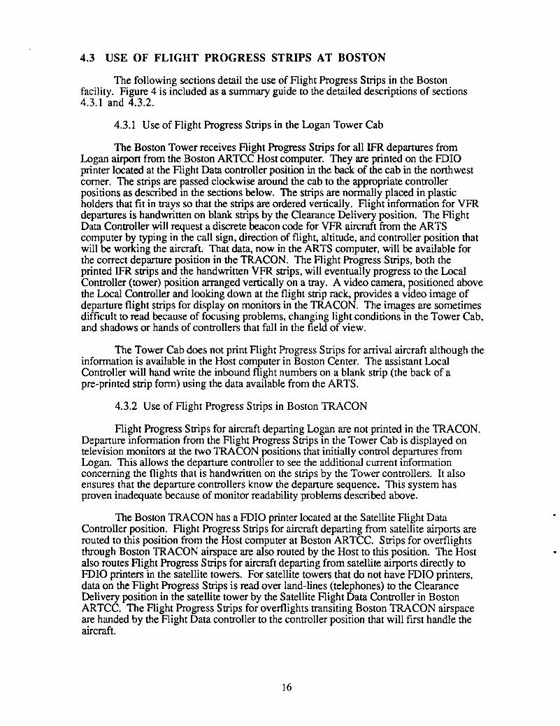
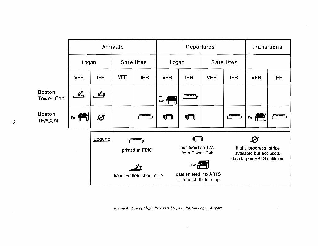
4.3 USE OF FLIGHT PROGRESS STRIPS AT BOSTON
The following sections detail the use of Flight Progress Strips in the Bostonfacility. Figure 4 is included as a summary guide to the detailed descriptions of sections4.3.1 and 4.3.2.
4.3.1 Use of Flight Progress Strips in the Logan Tower Cab
The Boston Tower receives Flight Progress Strips for all IFR departures fromLogan airport from the Boston ARTCC Host computer. They are printed on the FDIOprinter located at the Flight Data controller position in the back of the cab in the northwestcomer. The strips are passed clockwise around the cab to the appropriate controllerpositions as described in the sections below. The strips are normally placed in plasticholders that fit in trays so that the strips are ordered vertically. Flight information for VFRdepartures is handwritten on blank strips by the Clearance Delivery position. The FlightData Controller will request a discrete beacon code for VFR aircraft from the ARTScomputer by typing in the call sign, direction of flight, altitude, and controller position thatwill be working the aircraft. That data, now in the ARTS computer, will be available forthe correct departure position in the TRACON. The Flight Progress Strips, both theprinted IFR strips and the handwritten VFR strips, will eventually progress to the LocalController (tower) position arranged vertically on a tray. A video camera, positioned abovethe Local Controller and looking down at the flight strip rack, provides a video image ofdeparture flight strips for display on monitors in the TRACON. The images are sometimesdifficult to read because of focusing problems, changing light conditions in the Tower Cab,and shadows or hands of controllers that fall in the field of view.
The Tower Cab does not print Flight Progress Strips for arrival aircraft although theinformation is available in the Host computer in Boston Center. The assistant LocalController will hand write the inbound flight numbers on a blank strip (the back of apre-printed strip form) using the data available from the ARTS.
4.3.2 Use of Flight Progress Strips in Boston TRACON
Flight Progress Strips for aircraft departing Logan are not printed in the TRACON.Departure information from the Flight Progress Strips in the Tower Cab is displayed ontelevision monitors at the two TRACON positions that initially control departures fromLogan. This allows the departure controller to see the additional current informationconcerning the flights that is handwritten on the strips by the Tower controllers. It alsoensures that the departure controllers know the departure sequence. This system hasproven inadequate because of monitor readability problems described above.
The Boston TRACON has a FDIO printer located at the Satellite Flight DataController position. Flight Progress Strips for aircraft departing from satellite airports arerouted to this position from the Host computer at Boston ARTCC. Strips for overflightsthrough Boston TRACON airspace are also routed by the Host to this position. The Hostalso routes Flight Progress Strips for aircraft departing from satellite airports directly toFDIO printers in the satellite towers. For satellite towers that do not have FDIO printers,data on the Flight Progress Strips is read over land-lines (telephones) to the ClearanceDelivery position in the satellite tower by the Satellite Flight Data Controller in BostonARTCC. The Flight Progress Strips for overflights transiting Boston TRACON airspaceare handed by the Flight Data controller to the controller position that will first handle theaircraft.
]6
BostonTower Cab
Boston- TRACON--..l
Arrivals Departures Transitions
Logan Satell ites Logan Satell ites
VFR IFR VFR IFR VFR IFR VFR IFR VFR IFR
~ ~~~
twM9!I P
~~ 0 iMW!i~ ~D)
iMW!i ~~ iMMiiI P I P I P
Legend r"WWI"'1I P
printed at FDIO
hand written short strip
monitored on T.V.from Tower Cab
data entered into ARTSin lieu of flight strip
flight progress stripsavailable but not used;
data tag on ARTS sufficient
Figure 4. Use ofFlight Progress Strips in Boston Logan Airport

The Boston TRACON is unlike most other major TRACONS in that it does not usearrival Flight Progress Strips for traffic landing at Logan. This is because the ARTS datatag contains the arrival airport designation (no designation tag means Logan) and allnecessary information about the aircraft. This is a local ARTS software modificationknown as a patch. Flight Progress Strips for satellite arrivals are provided to the SatelliteController. VFR aircraft arriving at satellite airports and requesting services are given theappropriate frequency for the control position responsible for that airspace and assigned adiscrete beacon code by that controller. No flight strip information is entered into thesystem. VFR aircraft landing at Logan or transiting the TCA are also assigned a discretebeacon code and a "short" strip is prepared in the Tower Cab as described above.
4.4 FLIGHT STAGES AND THE PROCESSING OF FLIGHT PROGRESSSTRIPS
Departing and arriving aircraft proceed through certain stages or states during thedeparture or arrival process and the Flight Progress Strips move with them. At each stagethere is information known to the controller and/or pilot necessary to describe that stage.Additional steps must be taken to transfer the aircraft to a succeeding stage. The purpose ofthis section is to carefully describe each of the aircraft stages with particular attention toa) information needed by the controlling position, b) Flight Progress Strip status as afunction of aircraft stage, and c) the transfer of flight strip information.
4.4.1 Departing
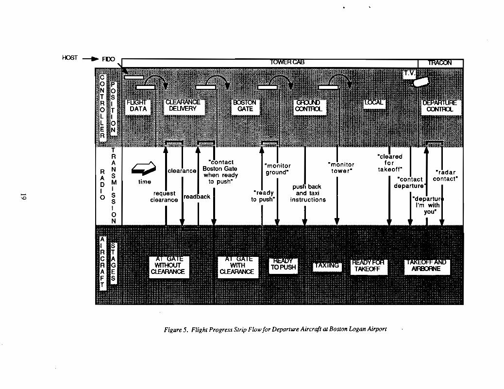
As an aircraft departs from Boston Logan airport, its Flight Progress Strip proceedsfrom one controller position to the next. Figure 5, at the end of this section, illustrates thetie-in between the progress of an aircraft through the departure sequence with theconcurrent progress of its Flight Progress Strip. In all, the Flight Progress Strip is handledby six different positions in Logan Tower. Each position makes a different use of theStrip. Depending on traffic intensity, some of the positions may be "combined," that is oneperson may perform the functions of two or more controllers.
4.4.1.1 Aircraft at Gate without Clearance
Airline aircraft parked at a gate normally have a published scheduled departure timeand destination. A "canned" flight plan stored on a computer tape and conforming to airlineand FAA requirements is automatically entered into the Host computer at Boston Center inNashua, New Hampshire and a Flight Progress Strip is printed at the FOlD in the LoganTower Cab at least thirty minutes prior to the proposed departure time. The pilots will get acopy of this flight plan from their company. If the planned flight is not on computer tape,then it will have to be filed through an Automated Flight Service Station (AFSS) or entereddirectly into the Host by a Flight Data position. Depending on the length of the flight, theremay be more than one "standard" flight route that complies with FAA preferred routerequirements. The pilot's choice of route and altitude will depend on weather and windsaloft as well as gross weight. For major airlines and most operators of large transportaircraft, all flights are conducted under instrument flight rules (IFR) regardless of theweather because the aircraft fly at altitudes that require an IFR clearance (in positive controlairspace above 18,000 feet mean sea level) and/or it is company policy. Some commuterflights are conducted VFR and it is legal for a large airline transport to me VFR belowpositive controlled airspace but this is not normally done in the Boston airspace.
18
RAoIo
Figure 5. Flight Progress Strip Flow for Departure Aircraft at Boston Logan Airport
Alternatively, the pilot may ftle an IFR or VFR flight plan directly through anAutomated Flight Service Station and this plan will be entered in the computer with thesame status as those entered from computer tape. This can be done a) in person at theAutomated Flight Service Station facility, b) by phone either through the briefer orspecialist or via special answering machines that record flight plans read by the pilot, orc) air filed with a specialist over the air to ground frequency. Any ATC facility, timepermitting, can process a request for ftling a flight plan and/or an instrument clearance.Instrument clearances or clearances to enter/exit/transit the Boston Tenninal Control Area(TCA) can be issued by the controlling facility without the pilot having to file a flight plan.These requests are made by the pilot to the controlling facility over the appropriate air toground frequency.
Every flight plan in the Host computer has a computer identification number and arevision number (if the flight plan is amended) that is assigned by the computer and stayswith the flight plan and is printed on every Flight Progress Strip at all facilities that handlethe flight. The computer does not automatically examine the requested routing to check forcompliance with current ATC traffic procedures. This is done by the Flight Data positionsat the initial controlling facilities. The Flight Data positions in the Tower Cab at Logan andat Boston Center in Nashua will examine the routing and make amendments as necessary.They will also ensure that the routing confonns with agreements with neighboring Centers(and TRACONS for aircraft operating under the Tower En Route Control program)confirming routing over the telephone if necessary. Nevertheless, at times flight planroutes are ftled and cleared that do not confmn with procedures and routings used bysubsequent control facilities and this requires en route amendments. Any amendments orchanges which result in a routing different than that requested by the pilot in his flight plantrigger the appearance of the code "FRC" on the Flight Progress Strip which stands for"Full Route Clearance." This indicates that the Clearance Delivery position should read thefull routing to the pilot instead of using the abbreviated "cleared as ftled" terminology whenreading the clearance.
The flight strip with the requested altitude and routing is printed in the Logan TowerCab and at the frrst en route sector of the Boston Center approximately thirty minutesbefore the requested departure time. The Flight Data position removes the strip from theprinter and checks the flight plan route for conformance with local traffic flow proceduresand with handoff agreements with neighboring facilities. If there are any doubts orquestions, the Flight Data Controller will call the succeeding facilities to verify the routing.The Flight Data Controller must also coordinate and record any delays or flow restrictions.The ATC system can impose departure delays due to flow control or en route spacing.Central Flow has a computer program that estimates congestion at specific airports andimposes ground delays for departing aircraft bound for the congested airports. Thesedelays are imposed by specifying Estimated Departure Clearance Times (EDCTs). TheTraffic Management Coordinator (fMC) at the Traffic Management Unit (fMU) in theBoston ARTCC relays the EDCT times to the airports via the Flight Progress Strip. Inaddition, the TMC can issues delays as part of the En Route Spacing Program (ESP) tocontrol traffic flow within Boston Center. ESP spacing delays are imposed to meethandoff metering requests (expressed as miles in trail or aircraft per time unit) fromneighboring Centers or TRACONS. The Flight Data Controller can consult one of theSystems Atlanta Information Display pages to determine which airports have current flowcontrol or en route spacing restrictions. The EDCTs and ESP delays are recorded in box 8on the Flight Progress Strips.
20
After confmning the routing and coordinating and recording any delays or flowcontrol restrictions, the Flight Data Controller puts the Flight Progress Strip into a plasticholder and places it in one of two rows in front of the Clearance Delivery position. It willremain in this position until the pilot requests his ATC clearance from Clearance Delivery.An IFR flight plan will "time out" after two hours unless a request is made to keep it activeto accommodate a delay. The length of time the flight plan will be held can be extended inthe event of delays but is limited by the ARTS capacity.
The pilots must also receive a weather briefing before departure, either through theircompany's weather department or from the FAA. Airline flights must also obtain aclearance from their company dispatch office before departure. The dispatcher checks,among other things, weight and balance, fuel, runway length requirements, conformancewith required maintenance, and the fIled route. Weight and balance data is used to calculateaircraft takeoff and climb performance including VI, VR, and V2 (the velocities at whichthe aircraft can continue the take-off in the event of engine failure, the velocity at rotation,and the velocity at lift-off respectively). Sometimes the aircraft will depart the gate withouthaving "the numbers" from its dispatch office and will receive the numbers and clearancefrom dispatch over its company ARINC radio frequency. If the aircraft departs the gateand enters the taxiway queue and then fails to receive a clearance from the dispatcher, it willhave to return to the gate.
4.4.1.2 Clearance Delivery
Historically, IFR clearances have been read to pilots over the Ground Controlfrequency, and at many less busy airports this is still the case. Congestion of the GroundControl frequency at Logan and other busy airports, however, has dictated the use of aseparate frequency known as pre-taxi Clearance Delivery or simply Clearance Delivery.This frequency, published on approach procedure charts, is used by the pilot to request hisor her ATC clearance prior to engine start or "push-back" from the gate. ClearanceDelivery is a separate position at major airports and the function of the Clearance Deliverycontroller is to read the ATC clearance to the pilot and monitor the "read-back" foraccuracy.
The clearance itself consists of the initial and en route routing (which may include apublished Standard Instrument Departure or SID procedure ), initial altitude and anexpected altitude clearance (along with a time or distance in which to expect the higheraltitude), a four-digit beacon or "squawk" code for the transponder, and a frequency fordeparture control. The portions of the clearance preceded by "expect" are given so that thepilot will follow those altitudes/routings in the event of lost communications. Since mostof the major airline flight plans are stored on computer tapes and presumably followcustomary ATC routings, it is usual for the route med to be approved and the route portionof the clearance to be read "cleared as fIled" or contain some initial vectors!routings andread "and then as filed" with the pilot having the responsibility for knowing what route wasrequested The Clearance Delivery position knows to read the entire routing to the pilot ifthe code letters "PRC" which stand for "Full Route Clearance" appear on the FlightProgress Strip. This is indicative of a change in the routing from that filed in the flightplan. A readback of the entire clearance by the pilot is customary to ensure accuracy,especially of the beacon code, initial altitudelheading, and departure control frequency. Atvery busy airports, including Logan, frequency congestion sometimes makes it impracticalfor a complete readback, and it has become a common practice to abbreviate the readback toessential information with the beacon code, initial altitude and departure frequency numbersbeing a minimum if the route is as filed.
21

When the Qearance Delivery controller finishes reading the clearance andmonitoring the readback, he or she passes the Flight Progress Strip to the Gate Holdposition known as "Boston Gate" who puts it in a stack of aircraft that will be in queue fortaxiing. The aircraft now has a clearance with ATC which is good from that moment untilwhenever the aircraft eventually makes it to the runway and is cleared for takeoff. Grounddelays encountered as a result of taxiway or runway queues are not "explained" to thosemembers of the ATC team who control the aircraft after departure; the subsequentcontrollers simply see the upcoming Flight Progress Strip as the aircraft enters theirairspace. Flight Progress Strips are printed at the appropriate controlling facilities along theroute based on the recorded departure time and updated actual and estimated times at enroute fixes.
4.4.1.3 Boston "Gate"
Clearance Delivery will instruct the airplane to contact "Boston Gate" on theappropriate frequency or to monitor Ground Control depending on the current traffic atLogan. The function of Boston Gate is to assist Ground Control in the sequencing ofdeparting aircraft. This reduces the number of aircraft waiting on the taxiway with enginesrunning and reduces frequency congestion on the Ground Control channel when traffic isheavy and there are a lot of aircraft waiting for taxi clearance. En Route meteringrequirements of neighboring sectors effect the sequencing of departing aircraft. Sinceaircraft in the queue on the taxiway cannot be easily resequenced, the Boston Gate positionassists in the taxiway sequencing by coordinating the order in which aircraft "push back"with Ground Control. The Flight Data position receives a daily restriction list from theTMU over the Gl interface with the Boston ARTCC Host computer. Restrictions, typicallyexpressed as limits (miles-in-trail) at departure fixes, are recorded in box 8 on the FlightProgress Strip of affected aircraft by the Flight Data position. Boston Gate organizes thepool of Flight Progress Strips, visible to the Ground Control position, to facilitatesequencing the taxiway queue to meet in-flight departure restrictions. Boston Gate willupdate the ESP and EDCf times on the Flight Progress Strip as that information isreceived. The Flight Progress Strip is transferred to the stack in front of the GroundControl position as he/she requests flights that are ready and meet the departure fix criteria.
When aircraft contact Boston Gate, they are instructed to call back when they areready to start their engines. Boston Gate will inform the flight of any expected delayimposed by Central Flow or the ARTCC. After any delay, Boston Gate will tell the pilot tomonitor the Ground Control frequency for taxi clearance. The aircraft do not contactGround Control but monitor the frequency until they are called. When Ground Control isready to authorize "push back," the controller will call the flight directly. Airline employeeramp controllers are responsible for aircraft at the gate and will monitor the aircraft duringthe push-back and engine start procedures.
Although Ground Control authorizes "push back," the liability for properseparation from other aircraft still lies with the airline and private gate controllers at thispoint. Theoretically, the aircraft could "push back" at any time and even taxi as long as itremained clear of the active taxiways. As a practical matter, traffic grid locks would occurin the gate area, so aircraft do not depart from the gate until cleared. The airlines howeverretain responsibility for taxi collision avoidance until the airplane is in the "movement area."
22
4.4.1.4 Taxiing
Aircraft receive clearance to "push back" and taxi to the departure runway from theGround Control controller position. Once an aircraft crosses into the "movement area" it isunder the jurisdiction of Ground Control. The nominal division of responsibility betweenGround Control and the Tower, as described in the Airman's Information Manual, is forGround Control to control aircraft on the ground until they are ready for departure. TheLocal Controller controls the active runways for arriving and departing aircraft. TheGround Control position must coordinate crossings of the active runways with the LocalController. Permission for the pilot to cross runways, including active runways, is implicitin the clearance to taxi to an active runway given by Ground Control unless specificallyprohibited by the use of instructions to "hold shon" of a runway. From paragraph 241 a.(5) of the Airman's Information Manual:
When ATC clears an aircraft to "taxi to" an assigned takeoffrunway, the absence of holding instructions authorizes the aircraft to"cross" all runways which the taxi route intersects except theassigned takeoff runway. It does not include authorization to "taxionto" or "cross" the assigned takeoff runway at any point. In orderto preclude misunderstandings in radio communications, ATC willnot use the word "cleared" in conjunction with authorization foraircraft to taxi.
Boston Logan follows this convention and the Ground Controller must coordinatewith the Local Controller any time an aircraft crosses an active runway. The use of "holdshoo" instructions is common. There can be more than one active runway depending onthe airpon configuration. The airpon configuration, in tum, depends on the surface winds,noise abatement procedures, and traffic. A given airpon configuration has cenain runwaysused for departures, arrivals or both. For a given airport configuration all runways in useare considered active regardless of the "rate" of use of that runway. It is possible for anaircraft to use a runway that is not considered active for the airpon configuration in effectat the time. For example, the primary departure runway(s) may be too shon for an aircraftin the heavy category or a high performance military jet fighter. In that case the aircraft canbe cleared to takeoff on a longer runway after coordination with the departure controller.Coordination with departure would not be required if the runway was considered an activerunway for the airpon configuration. In point of fact, any runway can be requested by apilot for take-off or landing in any direction, regardless ofthe airpon configuration, but asa practical matter such a request could result in a long delay. It is the pilot's responsibilityto ensure that the runway assigned is adequate for the performance of his or her airplane.
4.4.1.5 Take-Off
After an aircraft has crossed all active runways on its taxi route and is approachingthe end of the departure runway it will be instructed by Ground Control to monitor theTower frequency. When departure traffic is high, there will be a queue at the end of thedeparture runway. Aircraft will continue to monitor the Tower frequency while in thequeue. As aircraft enter the queue, the Ground Controller transfers the Flight ProgressStrips to the Local Controller in sequence. This is the stack that is viewed on the televisionmonitors in the TRACON. If the aircraft is going to use a runway other than a primarydeparture runway, this will be coordinated with the departure controller in the TRACONand written on the Flight Progress Strip. Aircraft do not contact the Tower when they areready to take-off. Instead, the Local Controller knows the aircraft identification and callsigns by virtue of their Flight Progress Strips and will contact the aircraft directly as theybecome first in line. When there is more than one primary runway in use for departures,
23
the Local Controller will maintain a separate sequenced stack of Flight Progress Strips foreach departure runway. Actually, there is a single vertical rack of strips separated by arunway designator strip to create the separate queues. As an aircraft becomes ftrst in line, itwill either be cleared for take-off or told to "taxi into position and hold" and subsequentlycleared for take-off. The Local Controller must separate departing and arriving aircraft onthe same and crossing runways. The Local Controller writes the departure time on theFlight Progress Strip as the aircraft is cleared for take-off. The strip is repositioned on thevertical rack below a separator strip designating departed aircraft. The last three or fouraircraft that have departed are kept in this position. The strips are removed approximatelythree or four minutes after departure.
4.4.1.6 Handoff to TRACON
After take-off, the departed aircraft is instructed to contact Boston departure on theappropriate frequency. The Flight Progress Strip is removed from the rack in front of theLocal Controller after a few minutes and the plastic holder tossed in a bin for reuse. TheFlight Progress Strip is collected by the Flight Data position and stored in a box bycategory of flight such as commuter, airliner, etc.
4.4.2 Arriving
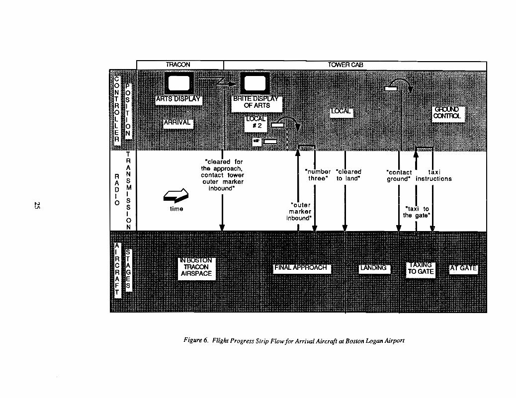
Arriving aircraft also follow a sequence as do their Flight Progress Strips althoughin this case the strips are handwritten "short" strips and the data is taken from the BRITEdisplay of the ARTS data. The process is illustrated in Figure 6 and discussed below.
4.4.2.1 In Boston TRACON Airspace
Aircraft are handed off from Boston Center to Boston approach at metering ftxes.Boston TRACON knows the airport conftguration (active runways) and vectors trafftcaccording to precoordinated arrival tracks, merging streams of trafftc as necessary.
Flight Progress Strip data for arriving aircraft is available in the Host computer atBoston ARTCC. The ARTS computer at Boston has a patch that prints the destinationairport in the data tag for arriving aircraft; (actually, aircraft arriving at Logan contain notag, aircraft arriving at satellite airports contain three letter tags). For this reason, BostonTRACON does not need the Flight Progress Strips and does not print them out at the FDIOprinter for arrival aircraft although strips for arrivals at satellite airports are printed andgiven to the satellite controller as an extra aid in keeping track of traffic. Flight ProgressStrips are of less importance for arrivals because future routing is of no concern; the aircraftare handed off from the Boston Center at coordinated ftxes, the destination and aircraft typeinformation is on the data tag, and it is known that the aircraft intends to land.
4.4.2.2 Local Handoff
The Local Controller is assisted by the Local 2 position who hand writes data onarrival aircraft on blank strips that are shorter than the normal Flight Progress Strips.Typically, the only information recorded is the aircraft identification and an "H" with acircle to signify aircraft in the "heavy" category or a "T" to signify VFR traffic. If theaircraft is landing on a secondary runway, that will also be noted. The ARTS display,including aircraft data tags, is available in the Tower Cab so that the Local controller canmonitor aircraft that are being sequenced by the TRACON. The data is tapped off of theARTS and is displayed on a special monitor in the Tower Cab known as the Bright RadarTower Equipment (BRITE) in deference to the high amount of light in the Cab. Thisequipment has the same readout, display controls, and keypad entry device that are
24
NVI
RADIo
time
"cleared forthe approach,contact towerouter marker
inbound"
"outermarker
inbound"
"clearedto land"
"contact taxiground" instructions
0,.1 '0the gate"
Figure 6. Flight Progress Strip Flow for Arrival Aircraft at Boston Logan Airport

available at radar JX)sitions in the TRACON. Aircraft are told when to contact the Tower byBoston Approach Control in the TRACON. During instrument approaches, this isnonnally at the outer marker when the aircraft is established on the localizer courseinbound, approximately five to seven miles from the runway. During visual meteorologicalconditions (VMC), the aircraft may be given a visual approach, but the flow of traffic andthe handoff to the Tower Cab is essentially the same.
4.4.2.3 Ground Control Handoff
After landing, the aircraft is told to turn off of the active runway and contactGround Control. The handwritten "short strip" is passed to Ground Control position. Thepilot contacts Ground Control when clear of the runway and requests taxi clearance to adestination on the airport. The Ground Controller clears the aircraft via a route of lettercoded taxiways. At Boston, the Local Controller will not instruct the aircraft to contactGround Control until the aircraft has cleared all active runways, i.e., if the aircraft turns offof the landing runway and must cross another runway that is in use, the Local Controllerwill instruct the aircraft to remain on hislher frequency.
4.4.2.4 Out-of··Movement Area
Ground Control is resJX)nsible for the safe movement of the aircraft until ittransitions out of the movement area where airline personnel will direct the aircraft into thegate. This occurs as the aircraft cross inside the truck lines.
26
5. SYSTEM REQUIREMENTS
The overriding requirement for the Automatic Strip Management System (ASMS) isthat it perfonn at least all of the functions of the current manual system with less than thecurrent workload and distraction imposed on the controller. The description of the currentsystem in the ftrst section of this requirements document therefore becomes an integral partof the ASMS functional requirements. ASMS must be the electronic equivalent of at leastthe system described in section 4. It must perfonn all of the services described in section 4and be compatible with the current operation. Any acceptable design must be compatiblewith current outside equipment, procedures, and interfaces; Le. ASMS cannot count onchanges to anything else in order to satisfactorily perfonn. At the same time, a successfulASMS design will facilitate and accommodate future hardware and operational changes andwill be designed to integrate easily with future systems such as AAS, TCCC, TATCA,Mode S, and ASTA.
This document is not intended to be a design requirements document, but adescription of the functional requirements. It is necessary at times to illustrate "types" ofdesigns in order to describe functional requirements but these should not be taken as designrequirements. Any design which accomplishes the same functions will be considered.Indeed, the ASMS program will of necessity involve prototyping of hardware and softwaredesigns and controller interfaces to test system acceptance and perfonnance.
5.1 HARDWARE AND INTERFACE REQUIREMENTS
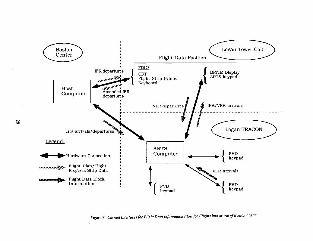
The initial ASMS design must integrate with the current system of flight datainformation flow employed at Logan airport. This involves interfaces primarily with theHost computer through the FDIO and the ARTS computer and display. The requiredinterfaces for information flow are illustrated in Figure 7. The interface between Logan andthe "outside world" for flight strips is primarily at the Flight Data positions in the TowerCab and TRACON.
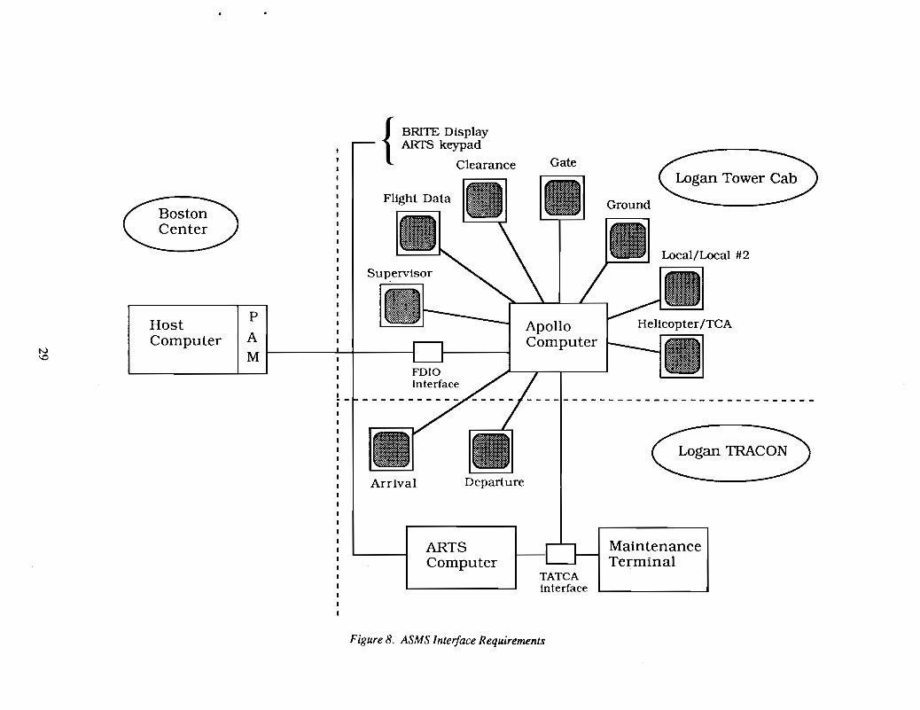
While Figure 7 is an illustration of "infonnation interfaces," Figure 8 is anillustration of hardware and hardware interfaces consistent with the infonnation flowrequirements. The system envisioned would have a stand alone computer (and probably arequired backup) with ten separate displays. Each of the displays would be interchangeableand each display would be capable of having the screen customized to any controllerposition by the supeIVisor; Le. the supeIVisor could decide that a particular screen would bethe Ground Control position. Any position will be able to access any other position'sdisplay with a single button push so that the Local position could, for instance, access theGround Control screen by pushing one button.
The ASMS computer must be capable of receiving Flight Progress Strip data thatcurrently goes to the FDIO printer. Any installation must also allow flight plans to be ftledfrom the Flight Data position to the Host, replacing, emulating, or interfacing with thecurrent Wespercorp FDIO equipment. The ASMS software should provide a "buffer"between the Flight Data position and the Host allowing the position to continue with his orher Flight Progress Strip work while ASMS interacts and waits for the HOST in requestingand ftling flight plans. The tap into the TATCA interface may be desirable if there isadditional useful information that can be gained from the Host but the FOIO interface is stillrequired because ASMS must be able to enter and amend flight plans (send infonnation intothe Host emulating the FDIO) and the hardware design should be capable of beingintroduced at other Towers that may not have a TATCA interface.
27
Gan Tower CVFlight Data Position
IV00
HostComputer
Legend:
......Hardware Connection
FDIO
{CRT
---.i.-...... Flight Strip PrinterKeyboard
ARTSComputer
BRITE DisplayARTS keypad
IFR/VFR arrivals
~ganmAC~
{PVD
......-----...~. keypad
'//////////~-' Flight Plan/FlightProgress Strip Data
--..... Flight Data BlockInformation
~RaITIValS
{PVDkeypad
Figure 7. Current Interfaces for Flight Data Information Flow for Flights into or out ofBoston Logan
ETower~Gate
ApolloComputer
Departure
FDIOinterface
{
BRITE DisplayARTS keypad
Clearance
Arrival•
P
A
M
HostComputer
ARTSComputer
TATCAinterface
MaintenanceTerminal
Figure 8. ASMS Interface Requirements
An interface with the ARTS computer is required to obtain data on arriving aircraftData on arrival aircraft is needed to replace the current procedure of writing "short strips"by hand based on data from the BRITE display and because it is required in order todisplay the interaction between arriving and departing aircraft needed by the Localcontroller display. ASMS will have to emulate the ARTS keypad for entering data blockinfonnation and therefore interface directly with the ARTS in a manner similar to theexisting BRITF)ARTS keypad connection to the Tower Cab.
ASMS must be designed to accommodate possible future interfaces with additionalairport equipment and status displays including the Airport Infonnation Distribution System(AIDS), the Low Level Wind Shear Alert System (lLWAS), Automatic WeatherObserving System (AWaS), Automatic Terminal Information System (ATIS), SystemsAtlanta Infonnation Display (SAIDS) computer, Digital Alimentary Setting Indicator(DASI), airport configuration input, runway visual range (RVR) measuring equipment,runway lighting status, and the computer generated airport users interface line whichprovides general information between the airport operator and user, etc. The use of thisinfonnation by ASMS will depend on the design of ASTA and TCCC and their interfacewith ASMS as well as possible stand alone functions that might be performed by ASMS attowers that might not have ASTA or TCCC.
The question of controller interaction devices will be addressed during theprototyping phase of ASMS but Figure 8 illustrates keyboards at the Supervisor's andFlight Data's positions in recognition of the more extensive inputs required by thesepositions.
S.2. SCREEN DESIGN REQUIREMENTS
This section describes the requirements for screen design by position. Figures 9a-eat the end of this section are sample illustrations of screens to aid in following thedescriptions. In these samples it is assumed that "windows" will be used that can beopened and closed by "clicking" on the appropriate highlighted section of a screen or frommenus as appropriate. It is also assumed that some form of single button clicking willtransfer information from one position display to the next as the "strip" progresses throughthe Tower. The actual screen designs and best methods of displaying information will berefmed in the prototyping and testing phases.
5.2.1 Supervisor
The supervisor's position and display will allow access to all information anddisplays. It will have the capability of reconfiguring the entire system so that any physicalscreen can act to support any controller position. The supervisor will also be able tocombine positions which would cause a position display to have the capability of alternatelyacting as more than one position. The supervisor's position will also be used to input anyadjustable parameters such as how far ahead of time (prior to departure) an aircraft ill willenter the queue at the Flight Data position.
The supervisor's position will be used to order the standardized traffic data reportsand controller time data and eligibility reports.
30
These uses suggest a menu driven multiple screen approach with a keyboard Thesupervisor does not need to be looking out of the Tower Cab while selecting and ordering aweekly traffic data report so the interface can be one that requires more direct interactionand attention to the system and display. There should be one supervisor's terminal in theTower Cab and one in the TRACON and they should be identical.
5.2.2 Flight Data
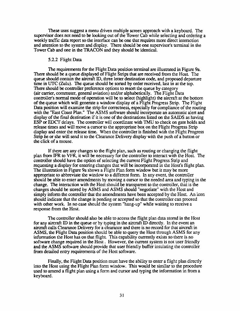
The requirements for the Flight Data position terminal are illustrated in Figure 9a.There should be a queue displayed of Flight Strips that are received from the Host. Thequeue should contain the aircraft ID, three letter destination code, and proposed departuretime in UTC (Zulu). The queue should be sorted by order received, last in at the top.There should be controller preference options to resort the queue by category(air carrier, commuter, general aviation) and/or alphabetically. The Flight Datacontroller's normal mode of operation will be to select (highlight) the aircraft at the bottomof the queue which will generate a window display of a Flight Progress Strip. The FlightData position will examine the strip for correctness, especially for compliance of the routingwith the "East Coast Plan." The ASMS software should incorporate an automatic alert anddisplay of the final destination if it is one of the destinations listed on the SAIDS as havingESP or EDCf delays. The controller will coordinate with TMU to check on gate holds andrelease times and will move a cursor to the appropriate box on the Flight Progress Stripdisplay and enter the release time. When the controller is fmished with the Flight ProgressStrip he or she will send it to the Clearance Delivery display with the push of a button orthe click of a mouse.
If there are any changes to the flight plan, such as routing or changing the flightplan from IFR to VFR, it will be necessary for the controller to interact with the Host Thecontroller should have the option of selecting the current Flight Progress Strip andrequesting a display for entering changes that will be incorporated in the Host's flight plan.The illustration in Figure 9a shows a Flight Plan form window but it may be moreappropriate to abbreviate the window to a different form. In any event, the controllershould be able to enter amendments by moving a cursor to the needed area and typing in thechange. The interaction with the Host should be transparent to the controller, that is thechanges should be stored by ASMS and ASMS should "negotiate" with the Host andsimply inform the controller that the amendments have been accepted by the Host An iconshould indicate that the change is pending or accepted so that the controller can proceedwith other work. In no case should the system "hang-up" while waiting to receive aresponse from the Host.
The controller should also be able to access the flight plan data stored in the Hostfor any aircraft ID in the queue or by typing in the aircraft ID directly. In the event anaircraft calls Clearance Delivery for a clearance and there is no record for that aircraft inASMS, the Flight Data position should be able to query the Host through ASMS for anyinformation the Host has on that flight This capability currently exists so there is nosoftware change required in the Host. However, the current system is not user friendlyand the ASMS software should provide that user friendly buffer insulating the controllerfrom detailed entry requirements of the Host software.
Finally, the Flight Data position must have the ability to enter a flight plan directlyinto the Host using the Flight Plan form window. This would be similar to the procedureused to amend a flight plan using a form and cursor and typing the information in from akeyboard.
31
WN
30 minutes prior to departureadjustable
Figure 9a. ASMS Flight Data Screen
ClearanceDelivery
5.2.3 Clearance Delivery
The Clearance Delivery screen, as illustrated in Figure 9b, should have separatequeues for air carriers, commuters, and general aviation aircraft and each queue should besorted alphabetically to facilitate finding and highlighting the flight when the clearance isrequested by the aircraft. The queue listing should include the aircraft ID (flight number),three letter destination code, and proposed departure time. The controller should have theability to produce a window with the Flight Progress Strip format by highlighting anaircraft in a queue. The controller should also be able to create a window with a fonnatcustomized to the clearance sequence. The clearance sequence is 1) destination, 2) initialrouting (runway heading, initial heading, vectors etc.) 3) en route routing (may be cleared·as filed), 4) initial altitude, 5) further altitude clearance and time or distance to expect thatclearance, 6) radar beacon code, and 7) departure control frequency. A sample clearancedelivery window with clearance is illustrated in Figure 9b
When an aircraft calls for clearance on the clearance delivery frequency, thecontroller will select and highlight the flight producing the clearance window. Afterreading and verifying the clearance, a cursor will prompt the controller to enter averification code signaling ASMS that the clearance has been received and read back by theflight crew. Additionally, cursors should prompt for gate and ATIS information codes ifthey are know. Alternately, the controller should be able to enter these codes in the FlightProgress Strip form window. A single button selection of the flight displayed in the FlightProgress Strip window or clearance window will signal ASMS that after checking forclearance verification the strip should go to the Ground Control position.
5.2.4 Boston Gate
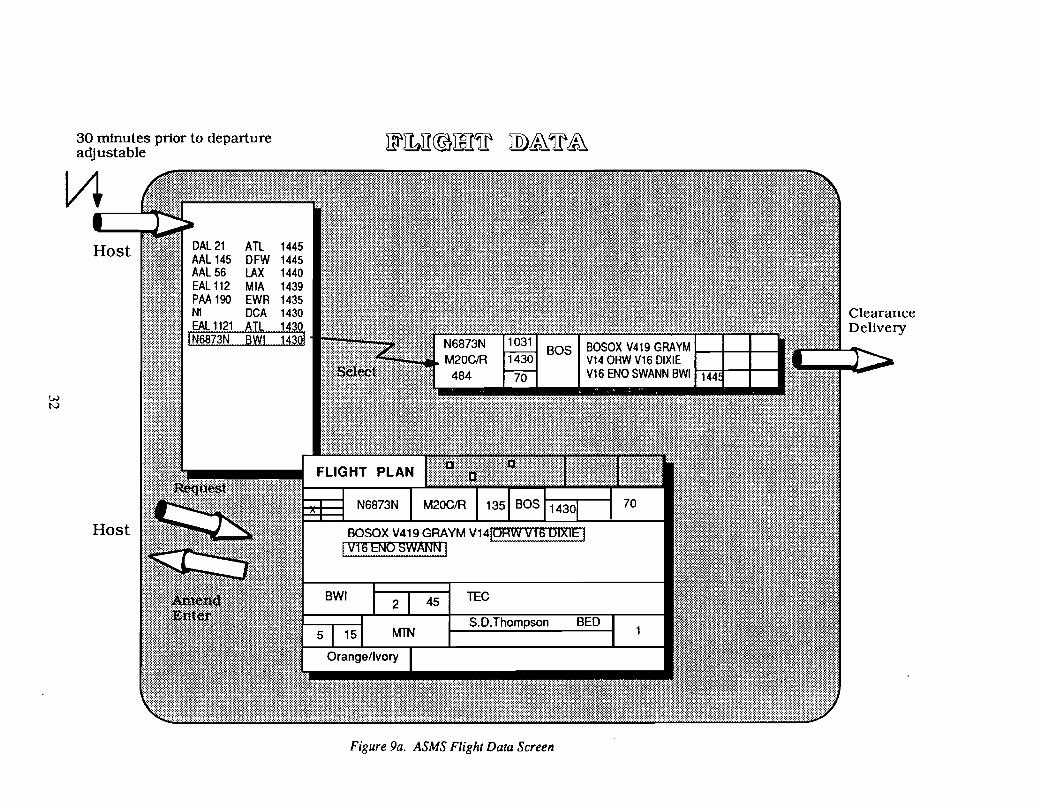
The Boston Gate display will receive "strips" from the Clearance Delivery position.There should be queues for each category (air carrier, commuter, and general aviation) offlight as illustrated in Figure 9c. The queues should contain the aircraft ID (flight number),aircraft type, gate, and initial departure fix and be sorted by first come first served with thelatest entry at the top and the oldest entry at the bottom. Boston Logan uses three letterdesignators for local use to depict departure fixes. The VOR fixes, such as Manchester,use the official three letter designator (MHT) that is recognized throughout the system butthe intersection fixes, such as BOSOX, which require five letters, are abbreviated to threeletters (BOX) for local Boston use.
The Boston Gate position will require the capability of displaying the flights in firstcome first served order by departure fix as illustrated in Figure 9c. Multiple windows withdifferent departure fixes should be allowed. This is because Boston Gate needs to be ableto supply aircraft to Ground by departure fix on a first come first served basis. BostonGate should, as with all displays, have the capability to select an aircraft in any queue anddisplay the Flight Progress Strip in a window. A cursor prompt will allow Boston Gate toenter the assigned runway. The position should also have the capability to update anyinformation in the notation boxes on the Flight Progress Strip using the same inputprocedures as the other positions.
33

ML 103 ATL 1445 AJC112 1445 DCA 1450AAL 435 DFW 1420 AJC 169 1430AAl517 lAX 1454 AJC 249 1428AAL 581 HOU 1417 AJC 846 1354AAL 981 EWR 1436 AJC 856 1432COA 361 DCA 1440 CMD 4845 1457COA 367 DFW 1412 CMD 4923 1414COA 387 lAD 1440 CVA 893 1423DAL 102 ATL 1440 GM 508 1430DAl586 GSO 1418 GM 559 1420DAL 589 ORO 1456 GAA 689 1440EAL 1091 ORD 1430 GM 767 1330EAL 1151 ATl 1425 G~
EAL 1159 MIA 1447 PR~
MID 225 MDW 1459 PRNWA 35 MEM 1356 VlPM 545 JFJ( 14TWA 61 JFJ( 14 the Baltimore WashintonTWA 754 LAX 14
ATCclearsMooney 6873N to International AirportUAL 49 SFO 13UAL 493 ORD 141
heading 180, vectors to V419, BOSOX,USA 345 PIT 141 viaturn right,
USA 691 DCA 14as filed
climb to maintain30 expect _70_ in _1_0_ min after departure
squawk code will be1031
contact departure on121. 4
Figure 9b. ASMS Clearance Delivery Screen
EAl1101 B727 2 BAF AJC 169 BE02 28 CTR C550 G/A CTRPAl 1292 B737 27 SEY AJC 315 BE02 28 HYA lR35 G/A ~tYIAAl981 MD80 22 SEY GAA 508 SF34 14 MHT M20C G/A BOXUSA 691 DC9 13 SEY ATl406 DH8 2A EXACOA 139 MD80 3A BAF GAA 538 BE02 14 MHTDAl 110 B767 30 MHT GAA 755 BE02 14 BOXEAl 137 B727 14 SEY CMD 4845 ATR42 14 BAFNWA 1649 DC9 18 MHTPAA 541 8727 6 BAFPAA 6541 B727 7 BAFUAl135 DC10 25 MHT
~VI
MH.I
8767DAl110 30GAA 508 SF34 14NWA 1649 DC9 18GAA 538 BE02 14UAL 135 DC10 25
Figure 9c. ASMS Boston Gate Screen
5.2.5 Ground Control
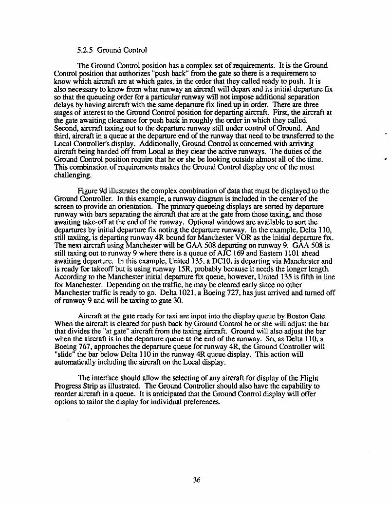
The Ground Control position has a complex set of requirements. It is the GroundControl JX)sition that authorizes "push back" from the gate so there is a requirement toknow which aircraft are at which gates, in the order that they called ready to push. It isalso necessary to know from what runway an aircraft will depart and its initial departure fIxso that the queueing order for a particular runway will not impose additional separationdelays by having aircraft with the same departure fIx lined up in order. There are threestages of interest to the Ground Control JX)sition for departing aircraft. First, the aircraft atthe gate awaiting clearance for push back in roughly the order in which they called.Second, aircraft taxing out to the departure runway still under control of Ground. Andthird, aircraft in a queue at the departure end of the runway that need to be transferred to theLocal Controller's display. Additionally, Ground Control is concerned with arrivingaircraft being handed off from Local as they clear the active runways. The duties of theGround Control position require that he or she be looking outside almost all of the time.This combination of requirements makes the Ground Control display one of the mostchallenging.
Figure 9d illustrates the complex combination of data that must be displayed to theGround Controller. In this example, a runway diagram is included in the center of thescreen to provide an orientation. The primary queueing displays are sorted by departurerunway with bars separating the aircraft that are at the gate from those taxing, and thoseawaiting take-off at the end of the runway. Optional windows are available to sort thedepartures by initial departure fIx noting the departure runway. In the example, Delta 110,still taxiing, is departing runway 4R bound for Manchester VOR as the initial departure ftx.The next aircraft using Manchester will be GAA 508 departing on runway 9. GAA 508 isstill taxing out to runway 9 where there is a queue of AlC 169 and Eastern 1101 aheadawaiting departure. In this example, United 135, a DClO, is departing via Manchester andis ready for takeoff but is using runway 15R, probably because it needs the longer length.According to the Manchester initial departure ftx queue, however, United 135 is ftfth in linefor Manchester. Depending on the trafftc, he may be cleared early since no otherManchester traffic is ready to go. Delta 1021, a Boeing 727, has just arrived and turned offof runway 9 and will be taxing to gate 30.
Aircraft at the gate ready for taxi are input into the display queue by Boston Gate.When the aircraft is cleared for push back by Ground Control he or she will adjust the barthat divides the "at gate" aircraft from the taxing aircraft. Ground will also adjust the barwhen the aircraft is in the departure queue at the end of the runway. So, as Delta 110, aBoeing 767, approaches the departure queue for runway 4R, the Ground Controller will"slide" the bar below Delta 110 in the runway 4R queue display. This action willautomatically including the aircraft on the Local display.
The interface should allow the selecting of any aircraft for display of the FlightProgress Strip as illustrated. The Ground Controller should also have the capability toreorder aircraft in a queue. It is anticipated that the Ground Control display will offeroptions to tailor the display for individual preferences.
36
..

Runway 4L
AJC 820 SF34 28CMD 4851 AT42 14
Figure 9d. ASMS Ground Control Screen
48
5.2.6 Local Control (Tower)
The Local Controller is concerned with the efficient, coordinated use of multiplerunways by arrival and depanure aircraft The primary information needed is the aircraftID, type, beacon code, and, for departing aircraft, initial departure fIx. The displayillustrated in Figure ge is oriented around the airport runway diagram and includes queuesfor departure aircraft by runway and displays of arriving aircraft with data blockinformation taken from the ARTS display.
The presumption is that Local will have little or no time for interaction with theASMS display. Currently, a Local 2 position aids the Local Controller at all times and willoperate the display. A moving bar will separate the departing aircraft that are coming underthe control of TRACON from the aircraft in queue awaiting departure. The aircraft in therunway queue appear as Ground Control slides the bar on his or her display to indicate thatthe aircraft is now in the departure queue. The aircraft does not contact the Tower butmonitors the Tower frequency and the Local Controller will use the displayed queue toidentify the aircraft ID as they become number one for departure. This is the procedureused today with the manual Flight Progress Strips. The only required input by the Local(or Local 2) is to move a bar to indicate that an aircraft is departing a runway or push abutton to switch an arriving aircraft's "short strip" (based on the ARTS data block) to theGround Control display.
5.2.7 HelicopterrrCA
The helicopterrrCA position will require a modified Local display to accommodateextensive VFR departures as well as the ARTS generated short strips for arrivals.
5.2.8 TRACON
The display in the TRACON will be identical to the Local display illustrated inFigure ge and will require no input or interaction by the controller.
5.3 HUMAN FACTORS REQUIREMENTS
It is clear that the design of the interface between the controller and ASMS will bethe key challenge in the design of any ASMS system. It is not the intention of thisdocument to solve the man/machine interface problems or dictate a specifIc design. Theapproach taken is to point out the functional requirements as is done in Sections 4 and 5.2and leave the details of design implementation to the prototype phase of the program.
However, there are certain features or requirements that can be discussed at thisstage. The presumption has been that there will be some kind of CRT display technologyemployed and that it will be incorporated in the shelf areas in the Tower Cab where theflight strip racks are now located. The space required by the displays should be no largerthan that now required by the flight strip racks and the displays should be as easy to read asare physical flight strips. This will require some advanced display technology because ofthe varying light conditions in the Tower Cab and because of the requirement for thecontrollers to look outside. At the very simplest level, the displays could be used to"replace" the flight strips now mounted in racks but it seems clear from the discussions ofthe current use of flight strips in Section 4 that "customizing" the display by position isdesirable. One approach is to use "windows" as is illustrated in Figures 9a-e. Thewindows can be customized to offer many alternate displays of the data and the display canbe "controlled" by the controller.
38
"
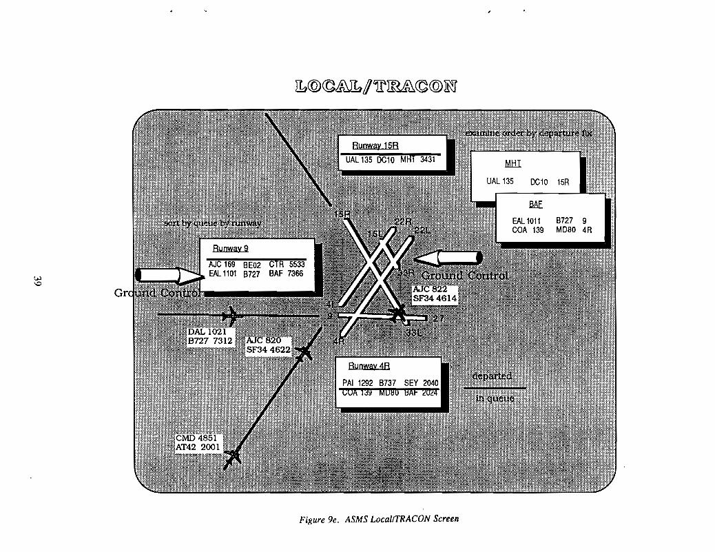
.ME
EAL 1011 8727 9eGA 139 MD80 4R
Figure ge. ASMS LocallTRACON Screen
MI::!.I
DC10 15R
:!;
1·1--
The human factors requirements on input vary greatly by position. The Flight Data,Clearance Delivery and Gate positions can pay more attention to the CRT screen and have agreater requirement to interact than the Ground Control or Local positions. The GroundControl and Local positions must devote most of their attention outside. Therefore, inputdevices that employ cursors, a mouse, menus, and a keyboard may be perfectly acceptableto the Flight Data position which must have the capability ofentering a flight plan, butwould be unacceptable to the Local Controller who inputs little or nothing and must belooking outside.
Some CRT display input and control devices should be common to all positions.For instance, a keypad or push buttons that allow selection and display of another positionshould be common to all positions. It is important to remember that the controllers changeposition on a regular basis and that most controllers are checked out and current at morethan one position. Therefore it is important that the different ASMS positions incorporatecommon input/output methods. If a series of buttons across the top of the display are usedto select the position display (Ground, Gate, etc.), then that should be common to allCRTs.
Each position follows a repeatable sequence of events with each aircraft most of thetime. Therefore, it seems reasonable to design an interaction system that requires the leastinput for a "normal" sequence. This "next logical sequence" (NLS) approach will allow acontroller to process the selected aircraft to its next stage with the single click of a button.For instance, after Clearance Delivery reads a clearance and monitors the readback for anaircraft, a single button click should remove that aircraft from the Clearance Deliverydisplay, close all open windows, indicate verification of the readback to the ASMScomputer, and send the strip to Boston Gate. This NLS approach can be incorporated inqueue displays so that the next logical aircraft in sequence is automatically selected orhighlighted for selection.
The answers to the most acceptable interaction devices, designs, and hardware willbe found during the prototype testing phase.
5.4 DATA BASE REQUIREMENTS
5.4.1 Archival and Retrieval Requirements
The Flight Progress Strip images that progress through the ASMS system shouldbe stored on line for at least 48 hours and should be automatically stored off line on a realtime basis. The off line storage device should be capable of storing at least one weeksworth of Hight Progress Strip images and have small inexpensive removeable cartridges ordisks that would allow indefinite storage of data. The Flight Progress Strip images that arestored should be time marked by ASMS by position and include all data input by thecontrollers. These should also include the "short strips" taken from the ARTS computerdata blocks and generated by ASMS.
Menu driven software, accessible at the supervisor's terminal, should allow thesupervisor to search through the on line or off line data base of stored Flight Strip imagesto fmd Flight Strips that meet the search criteria The search criteria should include at leastaircraft ID, time period, beacon code, initial departure fix, routing arrival or departurerunway and type. The search software should allow for input of multiple search criteria,i.e. the program should be able to find all American Airlines Boeing 727s that departed onrunway 4L between 1400Z and 1600Z.
40
5.4.2 Traffic Data Recording Requirements
Using the on and off line data base storage system described above, ASMS shouldoffer a menu driven software system accessible to the supervisor to generate traffic datasummary reports. The system should be capable of summarizing the data by: 1) arrivalsand departures; 2) aircraft category (heavy, large, small) or (air carrier, commuter, generalaviation); 3) runway used; 4) time period. Standardized report fonnats and parametersshould be stored so that the supervisor can select a standard report from a menu.
5.4.3 Operational Recording and Eligibility Requirements
The ASMS system should keep track of the acting controller by position byrequiring a log-in. The log-in should allow the recording of training time by trainer andtrainee. This data should be stored with the Flight Progress Strip data. A menu drivensoftware package should be provided that allows the supervisor to prepare standardizedsummary time reports including training and overtime. The system should provide thesupervisor with real time eligibility checks which includes algorithms for positioncertification, training, length of time at position, or any other constraint that woulddetermine a persons eligibility to act as a controller at that position. In no case should theASMS software prevent a controller from logging in, even if it violates a preset constraint.
5.5 OPTIMUM QUEUE MODULE
ASMS will have access to data on departing aircraft by gate, aircraft type, androuting including initial departure fix. It is possible that a knowledge based algorithmcould be developed to optimize the departure sequence by runway taking into accountarrivals (both known from ARTS or Host or predicted based on statistics), airportconfiguration, separation standards, flow control limits to initial departure fixes, andaircraft performance limits. The software design should at least make provisions for asoftware module designed to optimize departure queues. This could serve as a test bedforfuture ASTA software and for integration with TATCA.
41