Automated Commuter Train System - West Virginia...
33
West Virginia University College of Engineering and Mineral Resources Lane Department of Computer Science and Electrical Engineering Real Time Systems Spring 2012 Automated Commuter Train System Analysis Phase Abdulrahman Alatawi Essam Koshak March 16, 2012
Transcript of Automated Commuter Train System - West Virginia...

West Virginia University College of Engineering and Mineral Resources
Lane Department of Computer Science and Electrical Engineering
Real Time Systems
Spring 2012
Automated Commuter Train System
Analysis Phase
Abdulrahman Alatawi
Essam Koshak
March 16, 2012
Hany
Sticky Note
Overall Grade 99/100 This is an excellent effort and good report, The overall structure of the report is fine, except that the sections on P-Specs and C-Specs should be part of the capabilities section 2.2 in respective subsections. It is better to split the controllers and have PATs to specify activation/deactivations.

2
Table of Contents: Table of Figures: ........................................................................................................................................... 3
1. Scope..................................................................................................................................................... 4
1.1. Identification and System Overview ......................................................................................... 4
1.2. Document Overview .................................................................................................................... 5
2. Requirements ....................................................................................................................................... 6
2.1. Required States and Modes ........................................................................................................ 6
2.2. CSCI Capability Requirements – DFD 0 .................................................................................. 7
2.3. CSCI Capability Requirements – DFD 1 .................................................................................. 8
2.4. CSCI Capability Requirements – DFD 2 .................................................................................. 9
2.5. CSCI Capability Requirements – DFD 3 ................................................................................ 10
2.6. CSCI Capability Requirements – DFD 4 ................................................................................ 11
3. CSCI External Interface Requirements .......................................................................................... 12
3.1. Interface Identification and Context Diagram ....................................................................... 12
3.2. External Interface Data Definitions ........................................................................................ 13
4. CSCI Interface Requirements .......................................................................................................... 15
4.1. Process Specifications (P-Specs) .............................................................................................. 15
4.1.1. P-specs for Primitive of Monitor Train Status ............................................................... 15
4.1.2. P-Specs for Primitive Functions of Operate Train ........................................................ 16
4.1.3. P-specs for Primitive of Maintain Compartment Temperature ................................... 18
4.1.4. P-specs for Primitive Functions of Maintain Compartment Temperature ................. 20
4.2. Control Specifications (C-Specs) ............................................................................................. 22
4.2.1. C-Specs for Operate Train ............................................................................................... 22
4.2.2. C-Specs for Maintain Compartment Temperature ....................................................... 23
4.2.3. C-Specs for Maintain Schedule and Timing ................................................................... 24
5. CSCS Internal Data Requirement ................................................................................................... 25
6. Data Dictionary Entries .................................................................................................................... 26
7. Conclusion ......................................................................................................................................... 28
8. Team Performance ............................................................................................................................ 28
9. Appendix A ........................................................................................................................................ 29
9.1. Memorandum of proposal request .......................................................................................... 29

3
Table of Figures:
Figure 1: STD 0 - Control Specifications for the Automated Commuter Train ........................................... 6
Figure 2: DFD 0 – Data Flow Diagram for the Automated Commuter Train .............................................. 7
Figure 3: DFD 1 - Data Flow Diagram for the Monitor Train Status ........................................................... 8
Figure 4: DFD 2 - Data Flow Diagram for the Operate Train ...................................................................... 9
Figure 5: DFD 3 - Data Flow Diagram for Maintain Compartment Temperature ...................................... 10
Figure 6: DFD 4 - Data Flow Diagram for Maintain Schedule and Timing ............................................... 11
Figure 7: Context Diagram Automated Commuter Train System .............................................................. 12
Figure 8: STD 2 - Control Specifications for the Operate Train ................................................................. 22
Figure 9: STD 3 - Control Specifications for Maintain Compartment Temperature .................................. 23
Figure 10: STD 4 - Control Specifications for Maintain Schedule and Timing ......................................... 24
Figure 11: Automated Commuter Train Overview ..................................................................................... 33

4
1. Scope
1.1. Identification and System Overview
The Automated Commuter Train System is a fully automated commuter train system
which operates throughout the metropolitan area (Reference to the MEMORANDUM in
appendix A). Each train is equipped with its own control system to direct and monitor
on-train systems such as doors, temperature, brakes, engine, etc. Also, each train runs
according to a precise itinerary data coming from the central computer. Overall, the
design focuses only on the automation process of the on-train system. The requirements
of the On-Train Control System include:
Control system to direct and monitor on-train components and devices.
Allow the control system to be override by the operator in case of an emergency.
The system should be able to communicate with the central computer to get data
on operation modes, obstacles, repair requests, and itineraries.
The system should maintain to apply the four break modes according to specific
situations.
The system should response to different stop requests weather according to the
itineraries or passengers on board or at stations.
The system must keep records about each run including failures or repair
requests.

5
1.2. Document Overview
The document provides analysis to the different requirements of the Automated
Commuter Train System, specifically the requirements of the automation process of the
on-train system.
The document consists of the following types of requirements analysis:
Context Diagram of the system
Data‐Flow Diagrams (DFD)
State‐transition diagrams (STD)
Processes Specifications (C‐Specs)
Controls Specifications (C‐Specs)

6
2. Requirements
2.1. Required States and Modes
Figure 1 is the STD 0 Control Specifications for the Automated Commuter Train that
illustrate the states and mode of the system.
Train Off
Power up/ Activate Systems
Checking On-Train Systems
Operate Train Automatically
Wait to power-down
Power Down/ Monitor Time & Schedule, Maintain Temp, Disable
Systems
All Systems On/ Check All System ONRelease Safety Breaks
Maintain Compartment TempMonitor Schedule and Time
Operate Train
Operate Train Manually
Manual Control Off/
Run Train
Manual Control On/
Run Train
Time to Start Train
Ready to Power Down
Figure 1: STD 0 - Control Specifications for the Automated Commuter Train

7
2.2. CSCI Capability Requirements – DFD 0
Figure 2 is the DFD 0 Data Flow Diagram for the Automated Commuter Train is
illustrated by four functions that are briefly shown in detailed levels in the following
sections of this document. But, the STD 0 that illustrate the states and mode of the
system is identified above in Figure 1.
Figure 2: DFD 0 – Data Flow Diagram for the Automated Commuter Train
Maintain Compartment
Temp.
3
Monitor Train Status
1
Maintain Schedule and Timing
4
Operate Train
2
Temp. Settings
Time to run train
Control On-Train Systems
Activate/ Deactivate
Trac
k Tr
ain
Lo
cati
on
Itin
erar
y D
ata
Time D
ata
Next Stop Request
Next Stop Display
On-Train Messages
New
Sto
pin
g M
od
e
Start New Stopping Mode
Location
Destination Speed Range
Time to Run
Run Completed
Time to Open Doors
Power Train Up and Down
Enable/Disenable devices
Status of Manual Control
Ready to Power DownActivate/ Deactivate
System in Good Condition
Activate/Deactivate
Set Temperature
Date
Curr
ent T
empe
ratu
re
System Status
Ru
n R
epo
rt
Failu
re R
epor
t
Request Repair
Engine Data
Status Signals
Current Speed
Failu
re S
ign
als
Track
Contro
l Sign
alsDoors Status
Door Signals
Engine Engage/Disengage
Manual Control Initiation
Bre
ak S
ign
als
Passen
ger Co
rd
Itinerary

8
2.3. CSCI Capability Requirements – DFD 1
Figure 3 is the DFD 1 Diagram for Monitor Train Status is illustrated by two
primitive functions that are briefly described in the (P-Specs) section.
Monitor Failures
.1
Monitor Run.2
Maintenance DB
Failures R
epo
rt
Train Record
Every Ru
n R
epo
rt
All Runs R
eport
Request Repair
Status SignalsFailure Data
Engine Data
Sys. in good condition
Main
tenan
ce Data
System Statu
s
Figure 3: DFD 1 - Data Flow Diagram for the Monitor Train Status

9
2.4. CSCI Capability Requirements – DFD 2
Figure 4 is the DFD 2 Diagram for Operate Train is illustrated by two primitive
functions that are briefly described in the (P-Specs) section, and two control nodes that
also briefly described in (C-Specs) section.
Monitor Train Speed
2.2
Time Doors
2.1
Speed is More Than Maximum Speed
Speed is Less Than Minimum Speed
Control Train
Train Stopped
Maximum Speed = 0
Speed = Stop Speed
Enable/DisableTrigger
Target Speed RangeCurrent Speed
Doors O
pen Time
Location
Time Data
Manage Run-Time Emergency
Activate Manual Control
Turn Off Manual Control
Critical Failure SignalsEnable/Disenable
Delay DoorsTime to Close Doors
Brake Signals
Activate Passenger Input
Door Signals
Engine Engage/Disengage Train Ready to Power DownTime to Open DoorsControl Signals from Track
Door Status
Time Settings
Emergency Stop (Max Speed = 0)
Figure 4: DFD 2 - Data Flow Diagram for the Operate Train

10
2.5. CSCI Capability Requirements – DFD 3
Figure 5 is the DFD 3 Diagram for Maintain Compartment Temperature in is
illustrated by three primitive functions that are briefly described in the (P-Specs) section,
and one control node that is also briefly described in the (C-Specs) section.
Set Compartment
Temp..2
Monitor Compartment
Temp..3
Apply Season Temp.
.1
Temp
. MA
X &
MIN
Date
Temp. SettingsTemp. SettingsTemp. Range
Cu
rrent Tem
p.
Heat
Cool
Temp. Signal
Control Compartment Temp.STD
Activate / Deactivate
Figure 5: DFD 3 - Data Flow Diagram for Maintain Compartment
Temperature

11
2.6. CSCI Capability Requirements – DFD 4
Figure 6 is the DFD 4 Diagram for Maintain Compartment Temperature in is
illustrated by two primitive functions that are briefly described in the (P-Specs) section,
and one control node that is also briefly described in the (C-Specs) section.
Process Stop Requests
.1
Process Itineraries
.2
On
Tra
in M
essa
ges
Track Train Location
Control Stopping STD
Next Stop Display Start New Stopping Mode
Nex
t St
op
R
equ
est
Time Data
Itinerary Data
Start / Stop Signals
Time to open doors
Tim
e to
run
Loca
tio
n
Des
tina
tion
Spe
ed R
ange
Run
Com
plet
e
New Stopping Mode
Stop Train
Obstacle Signal
Train Mode
Start Train
Figure 6: DFD 4 - Data Flow Diagram for Maintain Schedule and Timing

12
3. CSCI External Interface Requirements
3.1. Interface Identification and Context Diagram
Train Automation
System
Doors
Breaks
Maintenance Database
Engin
Speaker
OperatorMaintenance
System
Climate control
Lights
Stopping cord
Set Temp.Status
ON / OFF
Status
Announcments
Status
Accel
erat
e / D
ecel
erat
e
Stat
us
Open / Close
Status
Apply break phase
Status
Stop RequestO
verride ControlStatus
Every run Report
Public Address
Loca
tion
Stat
us, F
ailu
re
Scanners
Obstacles
Central Computer
Posit
ion
of tr
ain
Serv
ice
Requ
est
Obs
tacle
s
Trai
n Itin
erar
y
Station Stop Button
Stop Request
Figure 7: Context Diagram Automated Commuter Train System

13
3.2. External Interface Data Definitions
o Control Climate
Set Temp.: Control output of the system to set the temperature
Status: Data input to the system contains the current temperature reading
o Lights
ON / OFF: Control output of the system to set the light status on or off
Status: Data input to the system contains the current status of lights
o Speakers
Announcements: Control output of the system to select the appropriate
announcement to the passengers
Status: Data input to the system contains the current status of the speakers if they
are working or not.
o Engine
Accelerate / Decelerate: Control output of the system to set the speed
Status: Data input to the system contains the current speed
o Public Address
Status: Data input to the system contains the current location
o Scanners
Obstacles: Data input to the system contains if the scanners sense any obstacles
in the train’s path
o Station Stop Button
Stop Request: Control output of the system to stop the train by passengers at the
station

14
o Stopping Cord
Stop Request: Control output of the system to stop the train by passengers inside
the train
o Breaks
Apply Break Phase: Control output of the system to set the appropriate break
phase
Status: Data input to the system contains the status of breaks if they work or not
o Doors
Open / Close: Control output of the system to open or close doors based on
itinerary or obstacles
Status: Data input to the system contains the status of doors if they are opend or
closed or obstructed
o Control Climate
Set Temp.: Control output of the system to set the temperature
Status: Data input to the system contains the current temperature reading

15
4. CSCI Interface Requirements
4.1. Process Specifications (P-Specs)
4.1.1. P-specs for Primitive of Monitor Train Status
NAME: 1.1
TITLE: Monitor Failures
INPUT/OUTPUT:
system_status: data_in
failures_report: data_out
request_repair: control_out
System_in_good_condition: control_out
BODY: This function monitor the system for failures, and in case of failure, it generate a
request repair and failure report
NAME: 1.2
TITLE: Monitor Run
INPUT/OUTPUT:
Engine_data: data_in
Status_signals: control_in
Every_run_report: data_out
BODY: This function monitor each run the train operate, it receives engine data and
controls for each run then execute only if the system of the train is in good condition,
lastly at end of each run it keep report in the train record which will be transmitted to the
maintenance database.

16
4.1.2. P-Specs for Primitive Functions of Operate Train
NAME: 2.1
TITLE: Time Train
INPUT/OUTPUT:
Time_Data: data_in
Location: data_in
Trigger: control_out
Delay_Doors: control_out
Doors_Open_Time: data_in
Time_to_Close_Doors: control_out
BODY: This function monitor doors opening and closing. Location and Time_Data will
indicate which side to open at each stop. When doors open at a stop, a timer will be
activated. The timer will tell it is appropriate to close the doors. Delay_Doors closing if
obstructed.
NAME: 2.2
TITLE: Monitor Train Speed
INPUT/OUTPUT:
Emergency_Stop : data_in
Target_Speed_Range : data_in
Current_Speed: data_in

17
Speed_is_Less_Than_Minimum_Speed: control_out
Speed_is_More_Than_Maximum_Speed: control_out
Train_Stopped: control_out
Maximum_Speed=0: control_out
Speed=Stop_Speed: control_out
BODY: This function monitors and regulates train speed. Based on the current speed and
target speed range, it provides the following threshold control signals:
Speed_is_Less_Than_Minimum_Speed, Speed_is_More_Than_Maximum_Speed,
Train_Stopped, Maximum_Speed=0, and/or Speed=Stop_Speed to the controller.
18
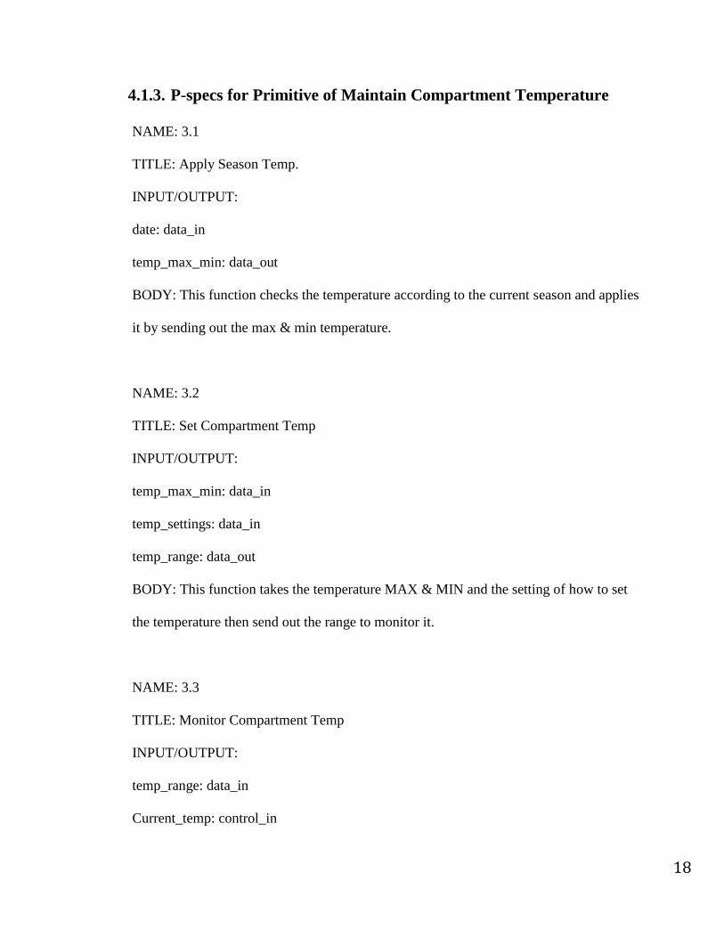
4.1.3. P-specs for Primitive of Maintain Compartment Temperature
NAME: 3.1
TITLE: Apply Season Temp.
INPUT/OUTPUT:
date: data_in
temp_max_min: data_out
BODY: This function checks the temperature according to the current season and applies
it by sending out the max & min temperature.
NAME: 3.2
TITLE: Set Compartment Temp
INPUT/OUTPUT:
temp_max_min: data_in
temp_settings: data_in
temp_range: data_out
BODY: This function takes the temperature MAX & MIN and the setting of how to set
the temperature then send out the range to monitor it.
NAME: 3.3
TITLE: Monitor Compartment Temp
INPUT/OUTPUT:
temp_range: data_in
Current_temp: control_in

19
temp_signal: contorl_out
BODY: This function takes the temperature range and the current temperature to specify
the appropriate temperature & send control signal to the controller.
20
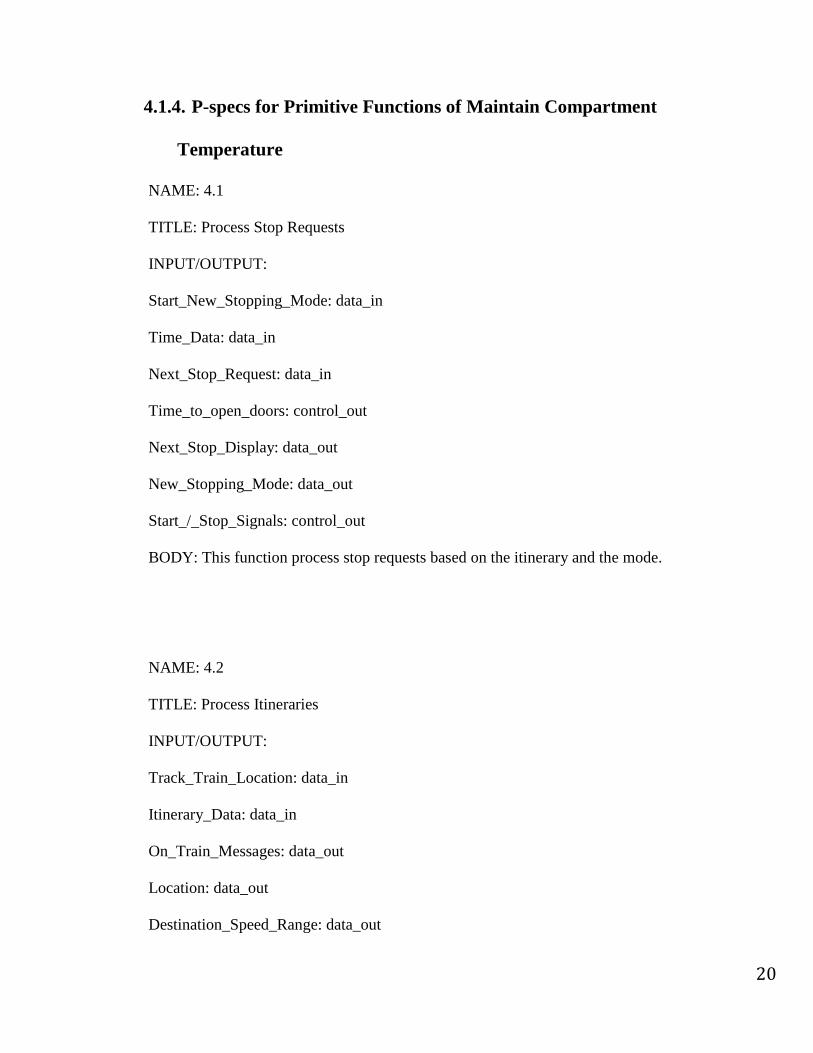
4.1.4. P-specs for Primitive Functions of Maintain Compartment
Temperature
NAME: 4.1
TITLE: Process Stop Requests
INPUT/OUTPUT:
Start_New_Stopping_Mode: data_in
Time_Data: data_in
Next_Stop_Request: data_in
Time_to_open_doors: control_out
Next_Stop_Display: data_out
New_Stopping_Mode: data_out
Start_/_Stop_Signals: control_out
BODY: This function process stop requests based on the itinerary and the mode.
NAME: 4.2
TITLE: Process Itineraries
INPUT/OUTPUT:
Track_Train_Location: data_in
Itinerary_Data: data_in
On_Train_Messages: data_out
Location: data_out
Destination_Speed_Range: data_out

21
Next_Stop_Request: data_out
Run_Complete: control_out
Time_to_run: control_out
Train_Mode: control_out
Obstacle_Signal: control_out
BODY: This function process the itinerary and by applying it based on the deferent
modes of operations and based on the obstacles provided by the central computer, also it
receive data from scanners of the train to track the current location where it also take
care of announcing each stop to the passengers.

22
4.2. Control Specifications (C-Specs)
4.2.1. C-Specs for Operate Train
Figure 8 is the state‐transition diagram for the Operate Train STD control in DFD2.
Docking at Station
Speed > Max Speed
Phase I Braking
Max Speed = 0
Stopping
Speed = 0
Phase II Braking
Door Opening
Doors Open
Timing Doors
Speed = Min Speed
Max Speed > 0
Time to Close Doors
Door Colsing
Door Obstructed
Accelerating
Idle
Speed = Max Speed
Speed < Min Speed
Speed < Min Speed
Time to Start Train
Release all Brakes
Train Stopped
Doors Closed
Time to Open Doors
Figure 8: STD 2 - Control Specifications for the Operate Train

23
4.2.2. C-Specs for Maintain Compartment Temperature
Figure 9 is the state‐transition diagram for the Control Compartment
Temperature STD control in DFD3. This figure shows how controlling the heater
and the cooler procedure work according to the different season temperature
settings based on the current date.
Heater/CoolerOFF
Heater ON Cooler ON
If cu
rr_t
emp
> m
ax_t
empIf curr_tem
p< min_tem
p
If cu
rr_t
emp=
max
_tem
pIf curr_temp = m
in_temp
Figure 9: STD 3 - Control Specifications for Maintain Compartment
Temperature

24
4.2.3. C-Specs for Maintain Schedule and Timing
Figure 10 is the state‐transition diagram for the Control Stopping STD control
in DFD4. This figure shows how stopping procedure work according to the
different modes that the train runs at, which are: Local, Express, and Request only
mode with regard to the obstacles data that comes from the central computer.
Apply Stopping Mode
Go toNext Stop
Start Train = True
Go toSpecified Stop
Start Train = True
Go without StoppingStart Train = True
ApplyStopping RequestStop Train = True
Train Mode = Express
Train Mode = Local
Train Mode = Request Only
Start / Stop Signals = StopObstacle Signal = True
Start / Stop Signals = StartObstacle Signal = False
Obstacle Signal = True
Obstacle Signal = False
Start / Stop Signals = StartObstacle Signal = False
Start / Stop Signals = StopObstacle Signal = True
Figure 10: STD 4 - Control Specifications for Maintain Schedule and Timing

25
5. CSCS Internal Data Requirement
o Temp. Settings Database:
Purpose: Stores range of temperature settings based on seasons
Location: DFD 0 ‐ Data Flow Diagram for the Automated Commuter Train
Inputs/outputs: Temp._Set
o Train Record Database:
Purpose: Stores each run information to be transferred later to the maintenance
database
Location: DFD 1 ‐ Monitor Train Status
Inputs/outputs: every_run_report
o Maintenance Database:
Purpose: Stores all reports of each run of trains
Location: DFD 1 ‐ Monitor Train Status
Inputs/outputs: all_run_reports
o Time Settings
Purpose: Stores doors opening time and delay times
Location: DFD 2 ‐ Operate Train
Inputs/outputs: Doors_Open_Time

26
6. Data Dictionary Entries
1. accelerate_decelerate_signal(control,primitive)
a. //signal sent to engine to accelerate or decelerate
2. announcments(data,compound)
a. = train_Next_Stop + itinerary_data
3. apply_break_phase_signal(control, primitive)
a. [“PHASE1”||”PHASE2”||”SAFETY”||”EMERGENCY”]
4. avery_run_report(data,primitive)
a. //carry each run information
5. status_failure(data,primitive)
a. //carry data about train devices status or failure messages
6. location(data,primitive)
a. //carry data about train current location
7. Obstacles_in_path(data,primitive)
a. //carry data about obstacles in the path of the train coming from Central Computer
8. Obstacles_from_scanners(data,primitive)
a. //carry data about obstacles in the path of the train coming from scanners
9. on_off_lights_signal(control,primitive)
a. [“ON”||”OFF”]
10. open_close_doors_signal(control,primitive)
a. [“OPEN”||”CLOSE”]
11. override_control_signal(control,primitive)
a. [“TRUE”||”FALSE”]
12. position_of_train(data,primitive)
a. //carry data about train current location
13. service_request_signal(control,primitive)
a. [“TRUE”||”FALSE”]

27
14. set_temp._signal(control,primitive)
a. [“AC”||”HEAT”||”NONE”]
15. status_announcement_trigger(control,primitive)
a. [“ON”||”OFF”]
16. status_climate_control_signal(control,primitive)
a. [“ON”||”OFF”]
17. status_lights_signal(control,primitive)
a. [“ON”||”OFF”]
18. status_speakers_signal(control,primitive)
a. [“ON”||”OFF”]
19. status_engine_signal(control,primitive)
a. [“ON”||”OFF” ||”Speed”]
20. status_breaks_signal(control,primitive)
a. [“OK”||”FAILED”]
21. status_doors_signal(control,primitive)
a. [“OK”||”FAILED”]
22. stop_request_from_station_button(control,primitive)
a. [“TRUE”||”FALSE”]
23. stop_request_from_stopping_cord(control,primitive)
a. [“TRUE”||”FALSE”]
24. train_itinerary(data,compound)
a. //carry data about current itinerary of the train

28
7. Conclusion
The system requirements analysis for the on-train control system was developed using the
specification of SWRA phase in the DOD standard MIL-STD-498 and the structured analysis
for real-time systems. The requirement analysis was then realized using Data Flow and
Control Flow Diagrams (DFDs/CFDs), Control specifications (C-specs), and Process
specifications (P-specs). That includes developing some State Transition Diagrams (STDs)
and Data Dictionary for the Train Control System. Furthermore, Data Dictionary Entries was
listed.
8. Team Performance
Our group consisted of two members. For the requirements analysis phase, three
meetings were held by the team besides communicating via email and online collaboration
using Dropbox tool. The first meeting was held in the class after class time and all members
were present. The team prepared the system requirements in-class presentation and split the
work up into parts. Each member was responsible for developing a different part of the
requirements analysis. Then, a meeting was held on February 26th in the Evansdale library.
The group communicated using email to develop the initial presentation. After the
presentation, the group made updates to their respective diagrams. Finally, a meeting was
held on March 14th in the Engineering Sciences Building. All members were present at this
meeting. The group discussed the overall report on the system requirements. Overall, the
group worked together quite well, and no problems were encountered.

29
9. Appendix A
9.1. Memorandum of proposal request
The following three memos compose the RFP for the Automated Commuter Train
System.
MEMORANDUM
TO: All Bidders
FROM: The Office of the Mayor
SUBJECT: Proposed Automated Commuter Train DATE: October 1, 1999
The City hereby requests proposals for the design and construction of an automated
commuter train system to operate throughout the metropolitan area beginning on
October 1, 2005. The proposal must provide support for the following requirements.
1.0 The trains in this system will be powered via a third rail. At no point will pedestrians
or auto- mobiles have access to the tracks.
2.0 The trains will be fully automated. Each train will be equipped with its own control
system to direct and monitor train acceleration, deceleration, stopping patterns, door
opening and closing, lighting, climate control, and announcements to passengers. The
operator's only charge will be to override the control system in the case of an emergency.
.3.0 Each train will run according to a precise itinerary. Trains will stop and start at the
appropriate locations and times. Each train will record this information for every run. It
will send this information in a report to the Maintenance Database at the end of each run.
4.0 Each train will be equipped with a self-monitoring engine and with the following
automated on- train systems: doors, brakes, lights, public address, and climate control. In

30
the event of a malfunction, manual controls will be enabled and monitored by the on-
train control system.
4.1 Each train will have four separate brake systems: phase I brakes for general speed
regulation, phase II brakes for stopping the train, emergency brakes for stopping the train
in the event of failure by either phase l or II brakes, and safety brakes for extra security
when the train stops to load and unload passengers.
4.2 Each train will have two separate door systems, left and right. Itineraries will
indicate which side to open at each stop. When doors open at a stop, an on-train timer
will be activated. The timer will tell the system when it is appropriate to close the doors,
given the stop and the time of day. Doors will not close fully until they are unobstructed.
5.0 The Maintenance Computer System will keep complete and up-to-date records on all
trains, communications hardware, and other components of the automated commuter
train network. The Maintenance System Database will store service and repair histories
for all these components.
6.0 In the event of equipment failure or accident, the on-train control system will notify
the Maintenance System automatically, and will provide precise data about the problem.
Appropriate data will be made available to maintenance crews before they make service
calls.
7.0 Each train will be equipped with scanners to warn it of any obstacles in its path.

31
MEMORANDUM
TO: All Bidders
FROM: City Planning Department
SUBJECT: Off-Train Systems for Proposed Automated Commuter Train
DATE: October 5. 1999
This memo documents a change to paragraph 7.0 in the Mayor's October 1 memo.
7.1 Information about obstacles in the train's path will come from a Central Computer
system. The Central Computer will monitor the positions of all vehicles on all track
sections. The Central Computer system will provide information about obstacles in the
train's path such as a service vehicle or another train. This system will also warn the train
about traffic signals and track switches as well as turns and gradient changes in each
section of track.
7.2 A communications network running parallel to the track will link the Central
Computer to each train. Messages will pass from train to network {or network to train)
via trackside devices located on each track section.
7.3 The Central Computer system will coordinate scheduling data for all trains. It will
send an appropriate itinerary to each train in the automated commuter train network. The
Central Computer system will be capable of changing the schedule at any time and will
disseminate these changes throughout the system via the communications network.

32
MEMORANDUM
TO: All Bidders
FROM: City Planning Department
SUBJECT: Local, Express. and Request-Only Modes for Proposed Automated
Commuter Train
DATE: October 7.1999
The Automated Commuter Train proposal will account for the following additional
requirements:
8.0 The automated commuter train will operate in three modes: a Local mode in which it
will stop at every stop an Express mode in which it will go directly to a designated stop
and bypass all stops in between, and a Request-Only mode in which the train will stop
only if prompted by a passenger.
9.0 In Request-Only mode, passengers on the train will prompt the train to stop using the
Next Stop cord. Passengers waiting at the next stop will be able to stop an approaching
train using a button located at the stop.

33
Figure 11: Automated Commuter Train Overview