Autodesk Revit Structure 2011 Fundamentals...Revit Structure contains editing tools and temporary...
30
Revit Structure 2011 FUNDAMENTALS SDC www.SDCpublications.com Schroff Development Corporation PUBLICATIONS
Transcript of Autodesk Revit Structure 2011 Fundamentals...Revit Structure contains editing tools and temporary...
Revit Structure 2011
FUNDAMENTALS
SDC
www.SDCpublications.com
Schroff Development Corporation
PUBLICATIONS
5–1
Chapter 5Modify Commands
In this chapter you learn how to move and copy, rotate, array, mirror, align, split, offset, and trim/extend.
This chapter introduces:
Move and CopyRotateArrayMirrorAlignSplitOffsetTrim and Extend

5–2
Modify Commands
© 2010. Do not duplicate. 5–3
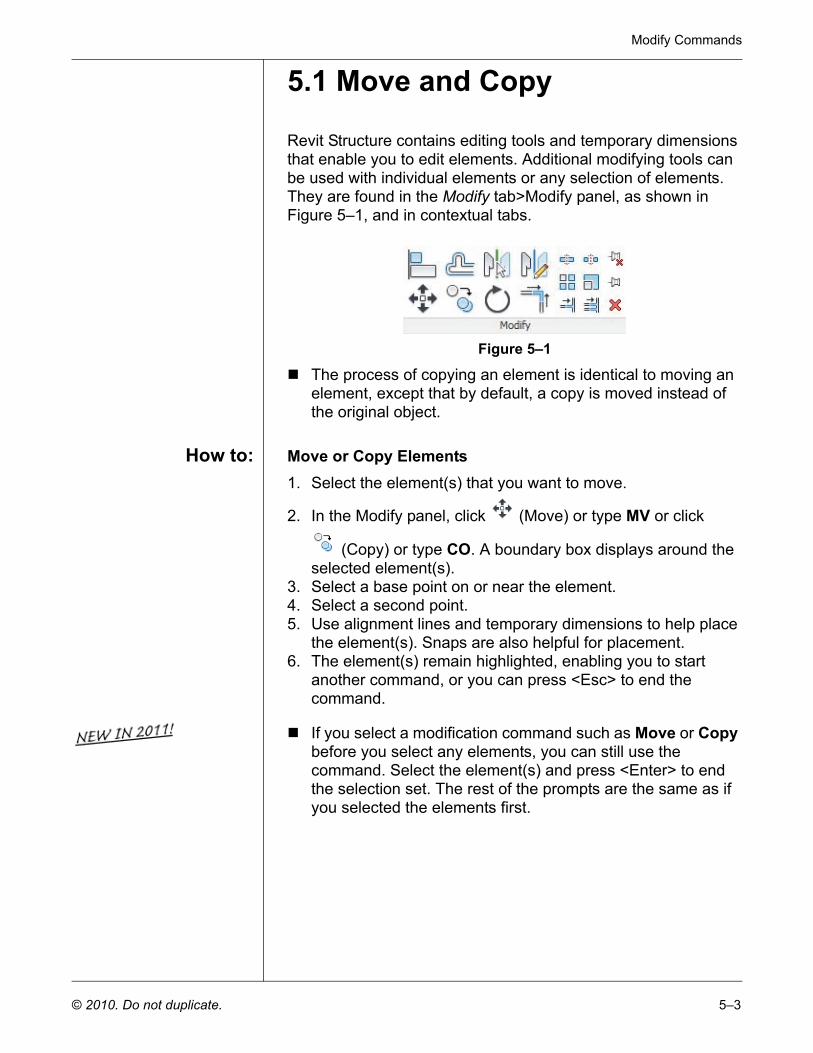
5.1 Move and Copy
Revit Structure contains editing tools and temporary dimensions that enable you to edit elements. Additional modifying tools can be used with individual elements or any selection of elements. They are found in the Modify tab>Modify panel, as shown in Figure 5–1, and in contextual tabs.
Figure 5–1
The process of copying an element is identical to moving an element, except that by default, a copy is moved instead of the original object.
How to: Move or Copy Elements1. Select the element(s) that you want to move.
2. In the Modify panel, click (Move) or type MV or click
(Copy) or type CO. A boundary box displays around the selected element(s).
3. Select a base point on or near the element.4. Select a second point.5. Use alignment lines and temporary dimensions to help place
the element(s). Snaps are also helpful for placement.6. The element(s) remain highlighted, enabling you to start
another command, or you can press <Esc> to end the command.
If you select a modification command such as Move or Copy before you select any elements, you can still use the command. Select the element(s) and press <Enter> to end the selection set. The rest of the prompts are the same as if you selected the elements first.
Autodesk Revit Structure 2011 Fundamentals
5–4 © 2010. Do not duplicate.
Move/Copy Options
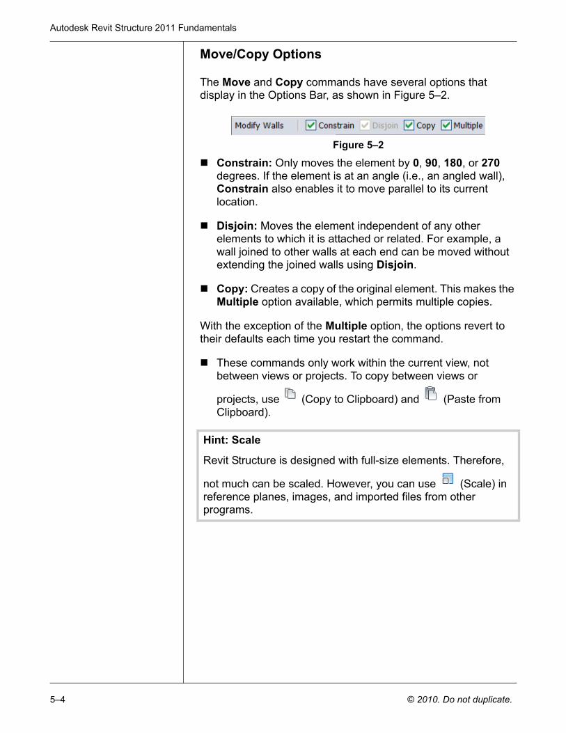
The Move and Copy commands have several options that display in the Options Bar, as shown in Figure 5–2.
Figure 5–2
Constrain: Only moves the element by 0, 90, 180, or 270 degrees. If the element is at an angle (i.e., an angled wall), Constrain also enables it to move parallel to its current location.
Disjoin: Moves the element independent of any other elements to which it is attached or related. For example, a wall joined to other walls at each end can be moved without extending the joined walls using Disjoin.
Copy: Creates a copy of the original element. This makes the Multiple option available, which permits multiple copies.
With the exception of the Multiple option, the options revert to their defaults each time you restart the command.
These commands only work within the current view, not between views or projects. To copy between views or
projects, use (Copy to Clipboard) and (Paste from Clipboard).
Hint: Scale
Revit Structure is designed with full-size elements. Therefore,
not much can be scaled. However, you can use (Scale) in reference planes, images, and imported files from other programs.
Modify Commands
© 2010. Do not duplicate. 5–5
5.2 Rotate
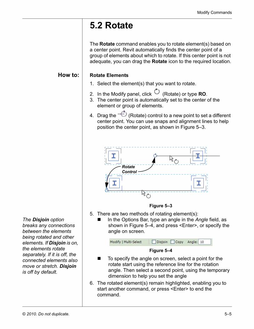
The Rotate command enables you to rotate element(s) based on a center point. Revit automatically finds the center point of a group of elements about which to rotate. If this center point is not adequate, you can drag the Rotate icon to the required location.
How to: Rotate Elements1. Select the element(s) that you want to rotate.
2. In the Modify panel, click (Rotate) or type RO.3. The center point is automatically set to the center of the
element or group of elements.
4. Drag the (Rotate) control to a new point to set a different center point. You can use snaps and alignment lines to help position the center point, as shown in Figure 5–3.
Figure 5–3
5. There are two methods of rotating element(s):The Disjoin option breaks any connections between the elements being rotated and other elements. If Disjoin is on, the elements rotate separately. If it is off, the connected elements also move or stretch. Disjoin is off by default.
In the Options Bar, type an angle in the Angle field, as shown in Figure 5–4, and press <Enter>, or specify the angle on screen.
Figure 5–4
To specify the angle on screen, select a point for the rotate start using the reference line for the rotation angle. Then select a second point, using the temporary dimension to help you set the angle
6. The rotated element(s) remain highlighted, enabling you to start another command, or press <Enter> to end the command.
Rotate Control
Autodesk Revit Structure 2011 Fundamentals
5–6 © 2010. Do not duplicate.
5.3 Array
In Revit, you can array an element based on two methods: Linear or Radial. A Linear array is line-based, while a Radial array is curve-based. Linear and Radial arrays are powerful tools when repeating layouts involving elements, such as custom trusses and rafters.
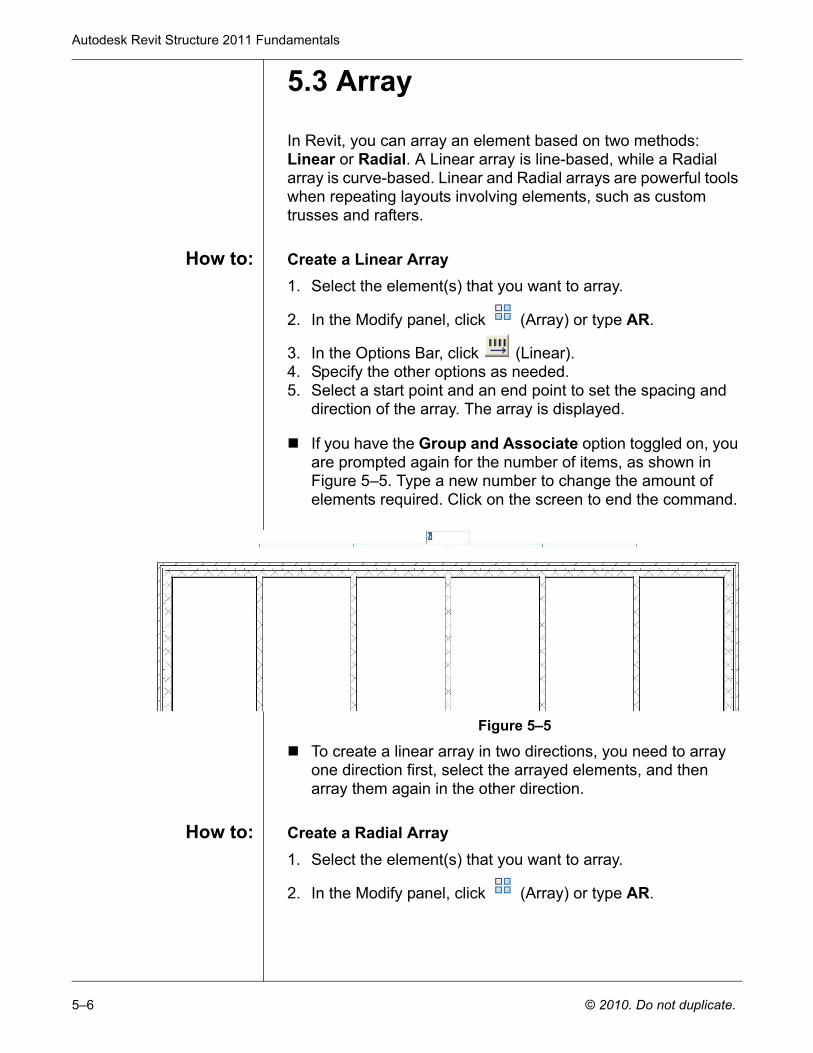
How to: Create a Linear Array1. Select the element(s) that you want to array.
2. In the Modify panel, click (Array) or type AR.
3. In the Options Bar, click (Linear).4. Specify the other options as needed.5. Select a start point and an end point to set the spacing and
direction of the array. The array is displayed.
If you have the Group and Associate option toggled on, you are prompted again for the number of items, as shown in Figure 5–5. Type a new number to change the amount of elements required. Click on the screen to end the command.
Figure 5–5
To create a linear array in two directions, you need to array one direction first, select the arrayed elements, and then array them again in the other direction.
How to: Create a Radial Array1. Select the element(s) that you want to array.
2. In the Modify panel, click (Array) or type AR.
Modify Commands
© 2010. Do not duplicate. 5–7
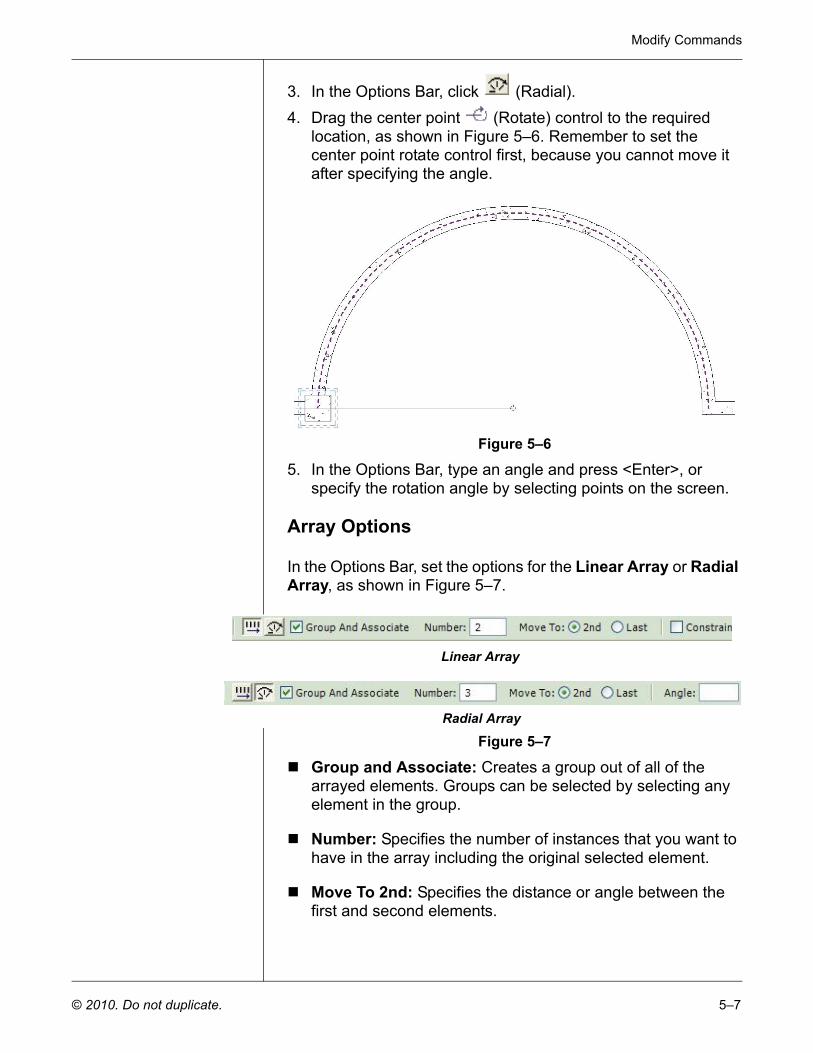
3. In the Options Bar, click (Radial).4. Drag the center point (Rotate) control to the required
location, as shown in Figure 5–6. Remember to set the center point rotate control first, because you cannot move it after specifying the angle.
Figure 5–6
5. In the Options Bar, type an angle and press <Enter>, or specify the rotation angle by selecting points on the screen.
Array Options
In the Options Bar, set the options for the Linear Array or Radial Array, as shown in Figure 5–7.
Figure 5–7
Group and Associate: Creates a group out of all of the arrayed elements. Groups can be selected by selecting any element in the group.
Number: Specifies the number of instances that you want to have in the array including the original selected element.
Move To 2nd: Specifies the distance or angle between the first and second elements.
Linear Array
Radial Array
Autodesk Revit Structure 2011 Fundamentals
5–8 © 2010. Do not duplicate.
Move To Last: Specifies the overall distance or angle of the entire array from the first to last elements.
Constrain: Restricts the direction of the array to only vertical or horizontal (Linear only).
Angle: Specifies the angle (Radial only).
Modifying Arrays
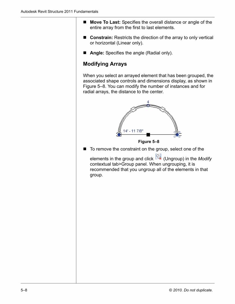
When you select an arrayed element that has been grouped, the associated shape controls and dimensions display, as shown in Figure 5–8. You can modify the number of instances and for radial arrays, the distance to the center.
Figure 5–8
To remove the constraint on the group, select one of the
elements in the group and click (Ungroup) in the Modify contextual tab>Group panel. When ungrouping, it is recommended that you ungroup all of the elements in that group.
Modify Commands
© 2010. Do not duplicate. 5–9
5.4 Mirror
The Mirror command is similar to mirroring within most other CAD drafting programs. In Revit, the Mirror command is frequently used to mirror large numbers of elements at the same time. When mirroring, it is important to consider the final result because Revit automatically joins elements (such as walls). Care should be taken when selecting the elements to mirror to achieve the required results.
How to: Mirror Elements1. Select the element(s) to mirror.2. In the Modify panel, select the method that you want to use:
(Pick Mirror Axis) or type MM. You are prompted to select an element as the Axis of Reflection (mirror line).
(Draw Mirror Axis) or type DM. you are prompted to select two points to define the axis about which the elements are going to mirror.
3. The new mirrored element(s) remain highlighted, enabling you to start another command, or press <Esc> to end the command.
By default, the original elements that were mirrored are not removed. To delete the original elements, clear the Copy option in the Options Bar.
Hint: Reference Planes
Establishing reference planes is useful in a building layout during the early design stages. Reference planes are dashed construction lines in your model that help define important working points, such as the centerline of the building. They can be any length and can be placed by drawing or by picking existing elements. By default, reference planes do not plot. Although they appear to be 2D elements, reference planes are infinite planes that extend through other views. For example, when a reference plane is drawn in a first floor plan, it displays in all other floor plans, corresponding elevations, and sections. This can be very helpful when lining up elements in the model.
In the Home tab>Work Plane panel, click (Ref Plane). In the Modify|Place Reference Plane tab>Draw panel, use either
(Line) or (Pick Lines) to draw the reference plane.
Autodesk Revit Structure 2011 Fundamentals
5–10 © 2010. Do not duplicate.
Practice 5a Manipulating ElementsEstimated time for completion: 10 minutes
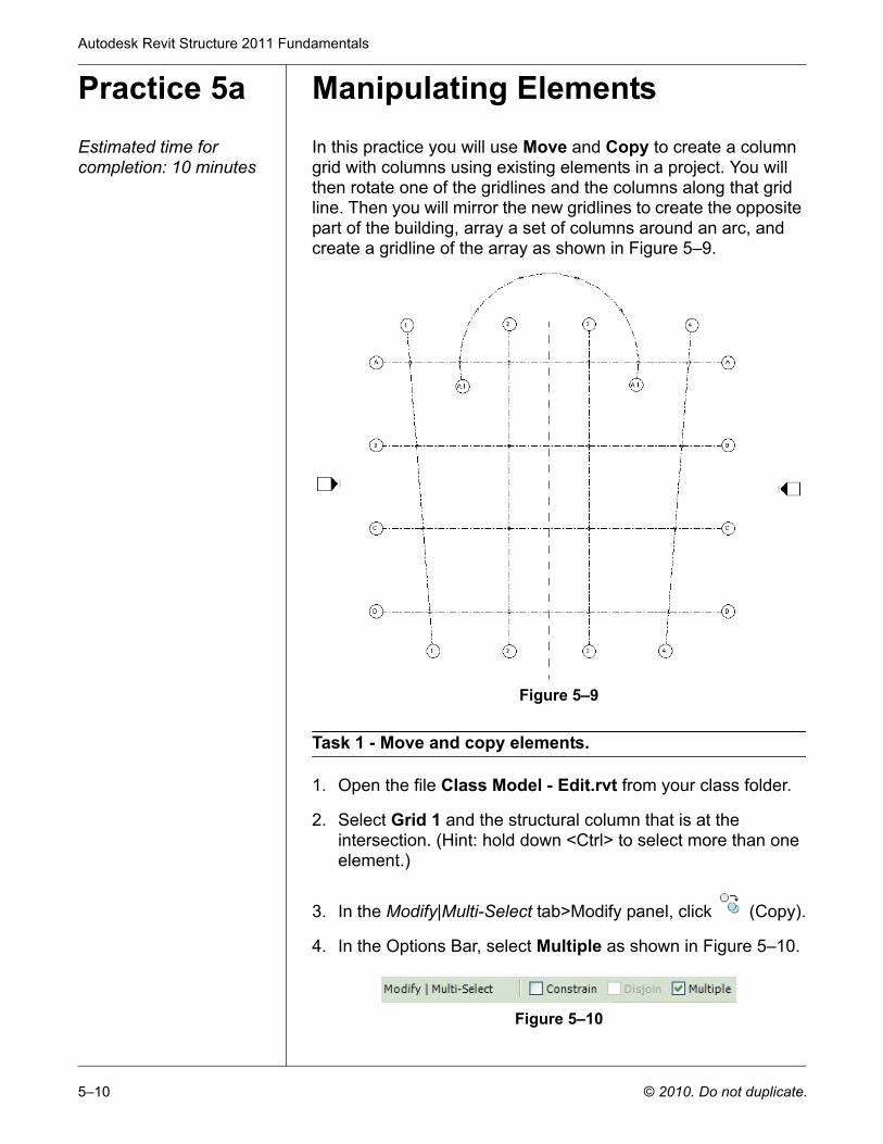
In this practice you will use Move and Copy to create a column grid with columns using existing elements in a project. You will then rotate one of the gridlines and the columns along that grid line. Then you will mirror the new gridlines to create the opposite part of the building, array a set of columns around an arc, and create a gridline of the array as shown in Figure 5–9.
Figure 5–9
Task 1 - Move and copy elements.
1. Open the file Class Model - Edit.rvt from your class folder.
2. Select Grid 1 and the structural column that is at the intersection. (Hint: hold down <Ctrl> to select more than one element.)
3. In the Modify|Multi-Select tab>Modify panel, click (Copy).
4. In the Options Bar, select Multiple as shown in Figure 5–10.
Figure 5–10
Modify Commands
© 2010. Do not duplicate. 5–11
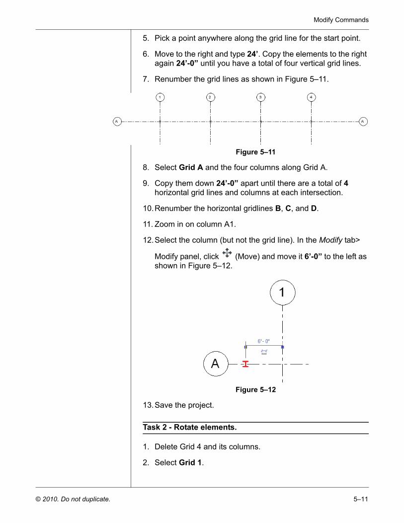
5. Pick a point anywhere along the grid line for the start point.
6. Move to the right and type 24’. Copy the elements to the right again 24’-0” until you have a total of four vertical grid lines.
7. Renumber the grid lines as shown in Figure 5–11.
Figure 5–11
8. Select Grid A and the four columns along Grid A.
9. Copy them down 24’-0” apart until there are a total of 4 horizontal grid lines and columns at each intersection.
10.Renumber the horizontal gridlines B, C, and D.
11. Zoom in on column A1.
12.Select the column (but not the grid line). In the Modify tab>
Modify panel, click (Move) and move it 6’-0” to the left as shown in Figure 5–12.
Figure 5–12
13.Save the project.
Task 2 - Rotate elements.
1. Delete Grid 4 and its columns.
2. Select Grid 1.
Autodesk Revit Structure 2011 Fundamentals
5–12 © 2010. Do not duplicate.
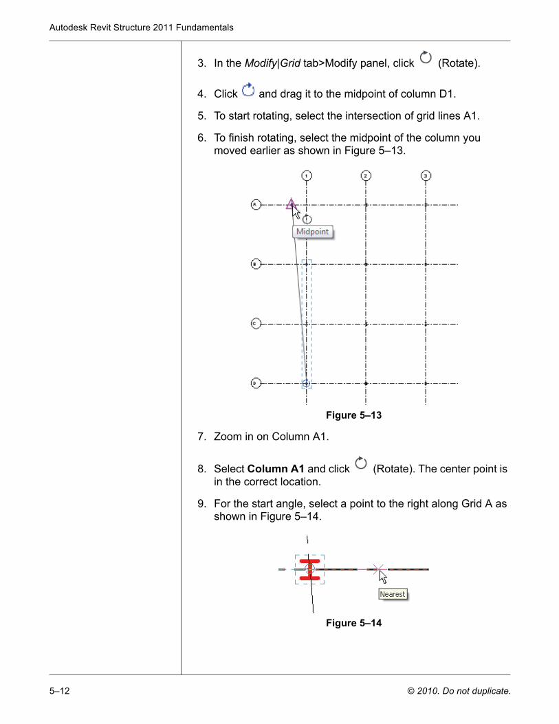
3. In the Modify|Grid tab>Modify panel, click (Rotate).
4. Click and drag it to the midpoint of column D1.
5. To start rotating, select the intersection of grid lines A1.
6. To finish rotating, select the midpoint of the column you moved earlier as shown in Figure 5–13.
Figure 5–13
7. Zoom in on Column A1.
8. Select Column A1 and click (Rotate). The center point is in the correct location.
9. For the start angle, select a point to the right along Grid A as shown in Figure 5–14.
Figure 5–14
Modify Commands
© 2010. Do not duplicate. 5–13
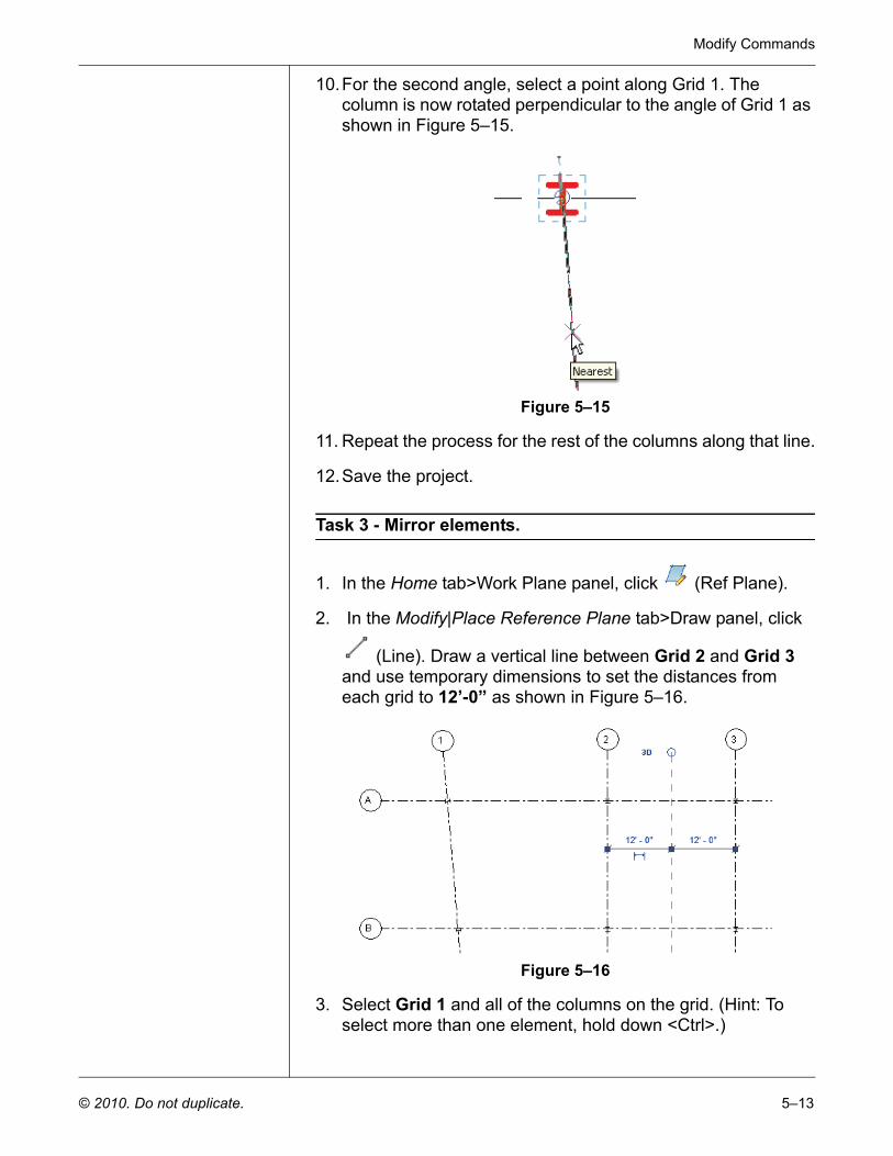
10.For the second angle, select a point along Grid 1. The column is now rotated perpendicular to the angle of Grid 1 as shown in Figure 5–15.
Figure 5–15
11. Repeat the process for the rest of the columns along that line.
12.Save the project.
Task 3 - Mirror elements.
1. In the Home tab>Work Plane panel, click (Ref Plane).
2. In the Modify|Place Reference Plane tab>Draw panel, click
(Line). Draw a vertical line between Grid 2 and Grid 3 and use temporary dimensions to set the distances from each grid to 12’-0” as shown in Figure 5–16.
Figure 5–16
3. Select Grid 1 and all of the columns on the grid. (Hint: To select more than one element, hold down <Ctrl>.)
Autodesk Revit Structure 2011 Fundamentals
5–14 © 2010. Do not duplicate.
4. In the Modify|Multi-Select tab>Modify panel, click
(Pick Mirror Axis).
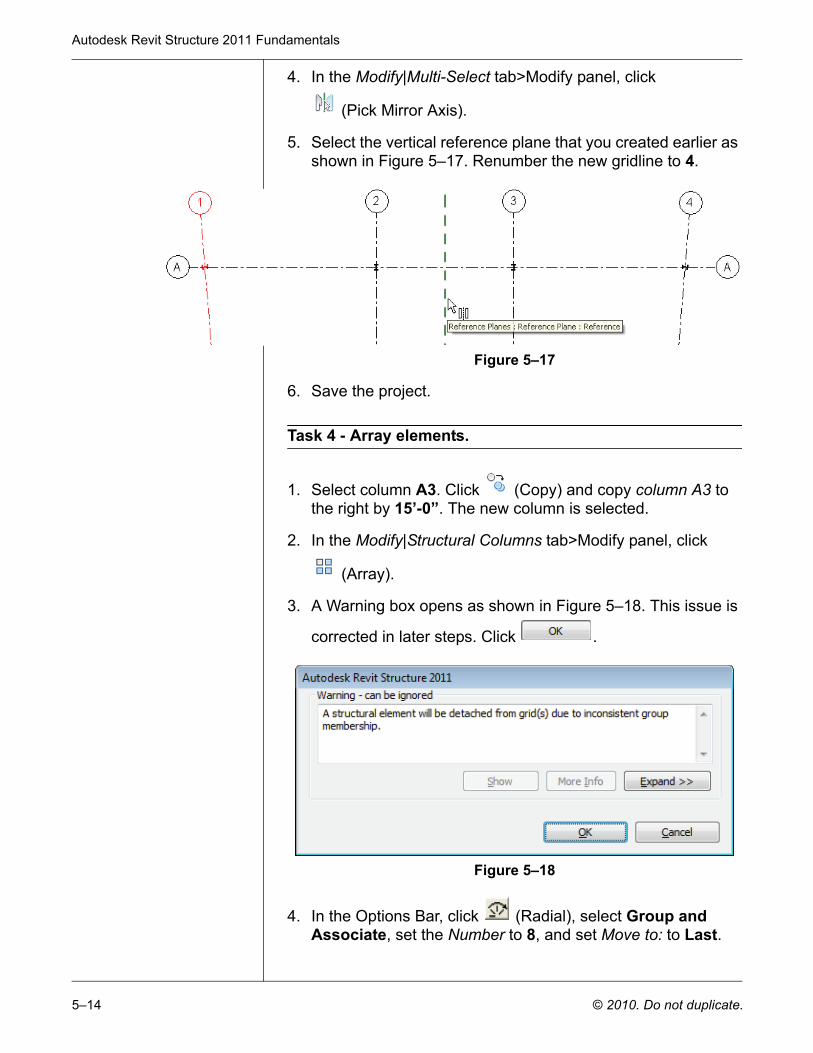
5. Select the vertical reference plane that you created earlier as shown in Figure 5–17. Renumber the new gridline to 4.
Figure 5–17
6. Save the project.
Task 4 - Array elements.
1. Select column A3. Click (Copy) and copy column A3 to the right by 15’-0”. The new column is selected.
2. In the Modify|Structural Columns tab>Modify panel, click
(Array).
3. A Warning box opens as shown in Figure 5–18. This issue is
corrected in later steps. Click .
Figure 5–18
4. In the Options Bar, click (Radial), select Group and Associate, set the Number to 8, and set Move to: to Last.
Modify Commands
© 2010. Do not duplicate. 5–15
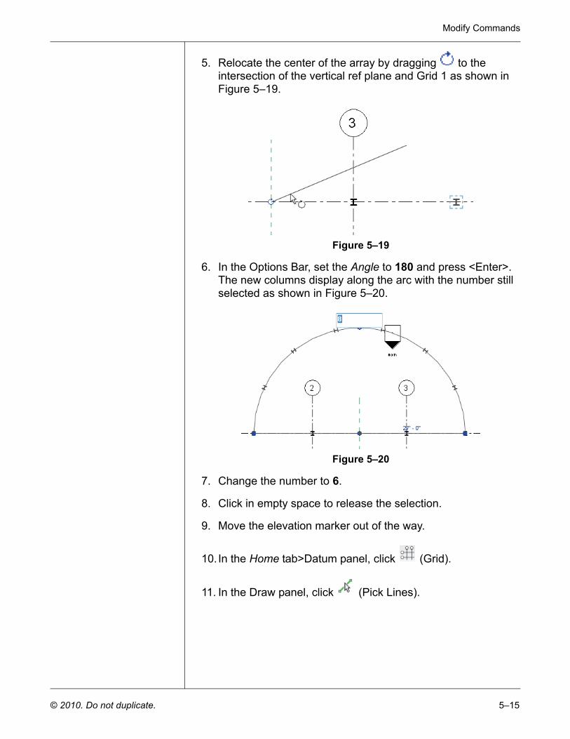
5. Relocate the center of the array by dragging to the intersection of the vertical ref plane and Grid 1 as shown in Figure 5–19.
Figure 5–19
6. In the Options Bar, set the Angle to 180 and press <Enter>. The new columns display along the arc with the number still selected as shown in Figure 5–20.
Figure 5–20
7. Change the number to 6.
8. Click in empty space to release the selection.
9. Move the elevation marker out of the way.
10. In the Home tab>Datum panel, click (Grid).
11. In the Draw panel, click (Pick Lines).
Autodesk Revit Structure 2011 Fundamentals
5–16 © 2010. Do not duplicate.
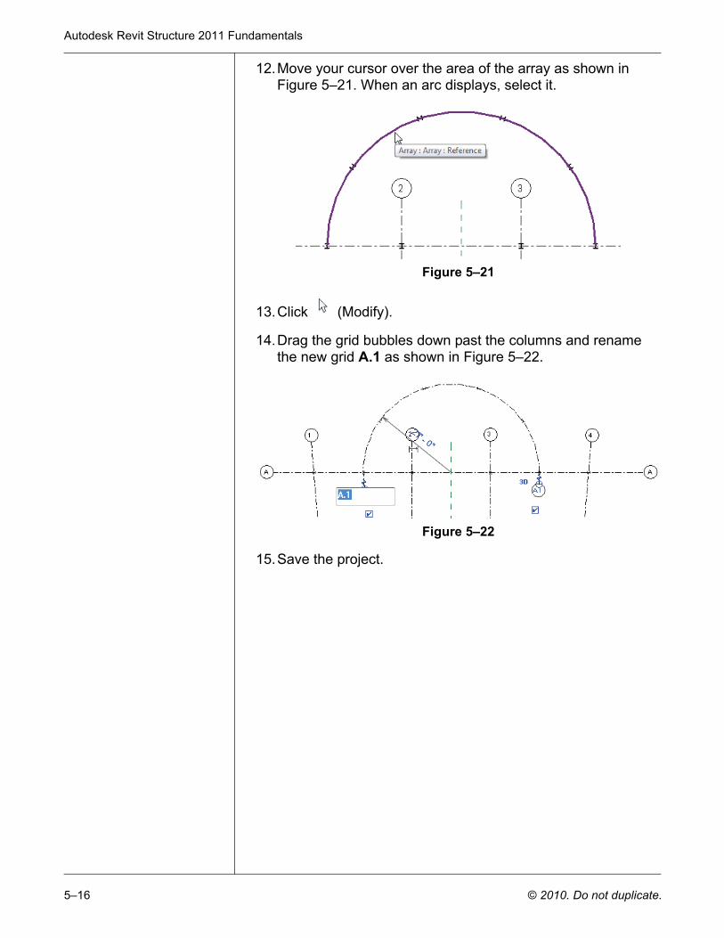
12.Move your cursor over the area of the array as shown in Figure 5–21. When an arc displays, select it.
Figure 5–21
13.Click (Modify).
14.Drag the grid bubbles down past the columns and rename the new grid A.1 as shown in Figure 5–22.
Figure 5–22
15.Save the project.
Modify Commands
© 2010. Do not duplicate. 5–17
5.5 Align
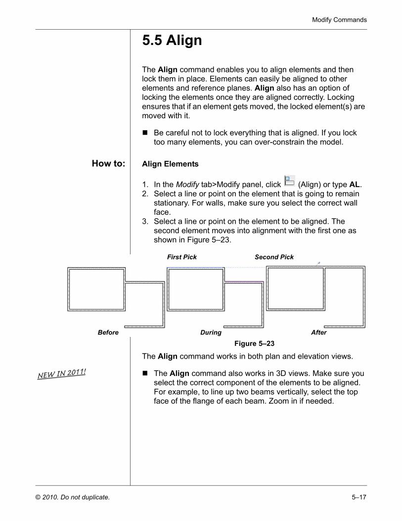
The Align command enables you to align elements and then lock them in place. Elements can easily be aligned to other elements and reference planes. Align also has an option of locking the elements once they are aligned correctly. Locking ensures that if an element gets moved, the locked element(s) are moved with it.
Be careful not to lock everything that is aligned. If you lock too many elements, you can over-constrain the model.
How to: Align Elements
1. In the Modify tab>Modify panel, click (Align) or type AL.2. Select a line or point on the element that is going to remain
stationary. For walls, make sure you select the correct wall face.
3. Select a line or point on the element to be aligned. The second element moves into alignment with the first one as shown in Figure 5–23.
Figure 5–23
The Align command works in both plan and elevation views.
The Align command also works in 3D views. Make sure you select the correct component of the elements to be aligned. For example, to line up two beams vertically, select the top face of the flange of each beam. Zoom in if needed.
First Pick Second Pick
Before During After
Autodesk Revit Structure 2011 Fundamentals
5–18 © 2010. Do not duplicate.
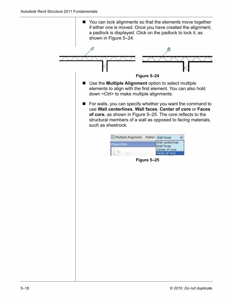
You can lock alignments so that the elements move together if either one is moved. Once you have created the alignment, a padlock is displayed. Click on the padlock to lock it, as shown in Figure 5–24.
Figure 5–24
Use the Multiple Alignment option to select multiple elements to align with the first element. You can also hold down <Ctrl> to make multiple alignments.
For walls, you can specify whether you want the command to use Wall centerlines, Wall faces, Center of core or Faces of core, as shown in Figure 5–25. The core reflects to the structural members of a wall as opposed to facing materials, such as sheetrock.
Figure 5–25
Modify Commands
© 2010. Do not duplicate. 5–19
5.6 Split
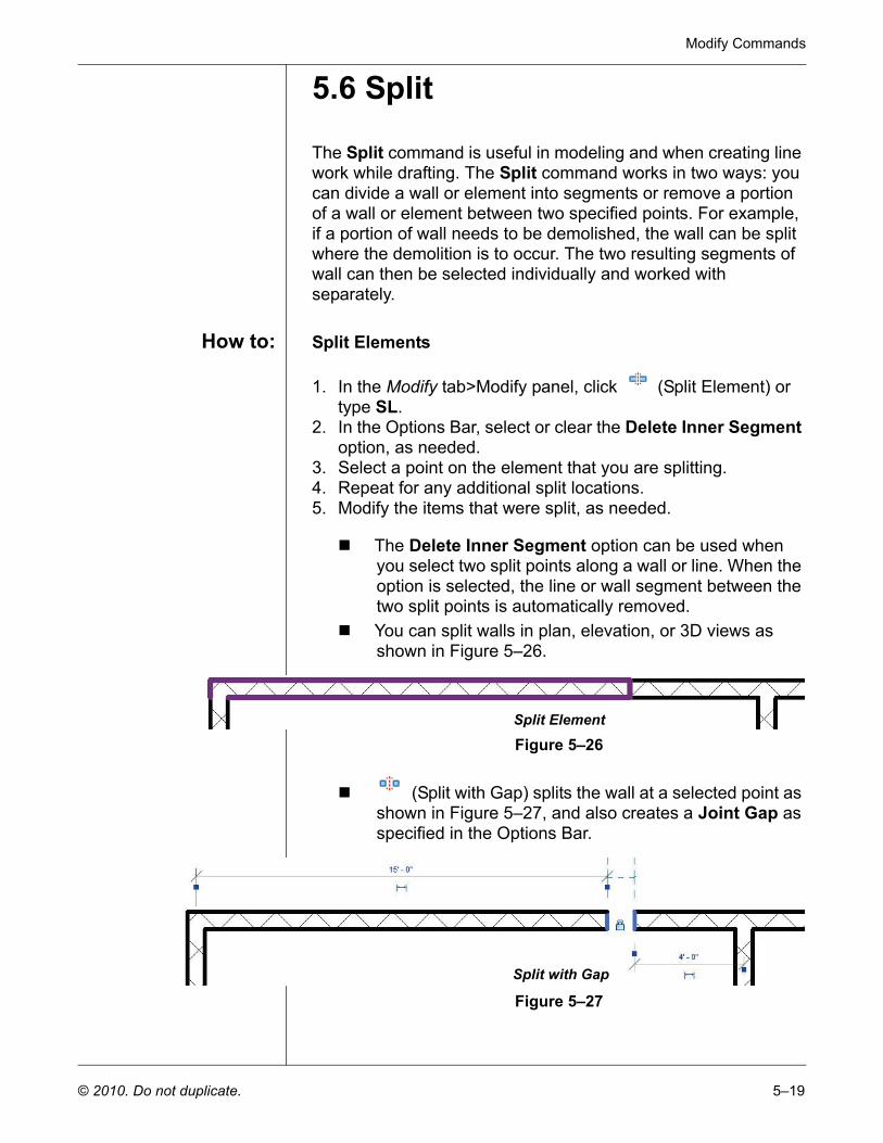
The Split command is useful in modeling and when creating line work while drafting. The Split command works in two ways: you can divide a wall or element into segments or remove a portion of a wall or element between two specified points. For example, if a portion of wall needs to be demolished, the wall can be split where the demolition is to occur. The two resulting segments of wall can then be selected individually and worked with separately.
How to: Split Elements
1. In the Modify tab>Modify panel, click (Split Element) or type SL.
2. In the Options Bar, select or clear the Delete Inner Segment option, as needed.
3. Select a point on the element that you are splitting.4. Repeat for any additional split locations.5. Modify the items that were split, as needed.
The Delete Inner Segment option can be used when you select two split points along a wall or line. When the option is selected, the line or wall segment between the two split points is automatically removed.You can split walls in plan, elevation, or 3D views as shown in Figure 5–26.
Figure 5–26
(Split with Gap) splits the wall at a selected point as shown in Figure 5–27, and also creates a Joint Gap as specified in the Options Bar.
Figure 5–27
Split Element
Split with Gap

Autodesk Revit Structure 2011 Fundamentals
5–20 © 2010. Do not duplicate.
5.7 Offset
The Offset command is not often used in Revit because it is embedded into the functionality of most commands. However, it is still available as a separate command and enables you to create parallel copies of walls, beams, model lines, and detail lines at a specified distance.
If you offset a wall in which components have been embedded, such as rebar, the elements are copied with the offset wall.
The offset distance can be set by typing the distance in the Options Bar (Numerical method shown in Figure 5–28) or by selecting points on the screen (Graphical method).
Figure 5–28
How to: Offset Elements using the Numerical Method
1. In the Modify panel, click (Offset) or type OF.2. In the Options Bar, select the Numerical option.3. In the Options Bar, type the required distance in the Offset
field.4. Move the cursor over the element that you want to offset. A
dashed alignment line previews the offset location as shown in Figure 5–29. Move the cursor to flip the sides, as needed.
Figure 5–29
5. Click to create the offset.6. Repeat Steps 4 and 5 to offset other elements by the same
distance or change the distance for another offset.
7. Press <Esc> or click (Modify) to end the command.
Modify Commands
© 2010. Do not duplicate. 5–21
How to: Offset Elements using the Graphical Method
1. In the Modify panel, click (Offset) or type OF.2. In the Options Bar, select the Graphical option.3. Select the element to offset.4. Select two points that define the distance of the offset and the
side on which it is to be applied. Type an override for the temporary dimension for the second point.
The Copy option is selected by default and creates a copy of the element being offset. If this option is cleared, the Offset command moves the selected element.
With the Numerical option, you can also select a chain of walls or lines for offsetting. Hover your cursor over one wall or line and press <Tab> until all of the required elements are highlighted. When the chain is visible, select the element that you want to offset. This enables you to offset all of them at once.
Walls connected at a corner, if offset to the outside of the corner, automatically extend to meet at the offset distance.
Autodesk Revit Structure 2011 Fundamentals
5–22 © 2010. Do not duplicate.
5.8 Trim and Extend
The Trim/Extend command enables you to either Trim or Extend walls, beams, braces, and lines. There are three trim methods: Trim/Extend to Corner, Trim/Extend Single Element, and Trim/Extend Multiple Elements.
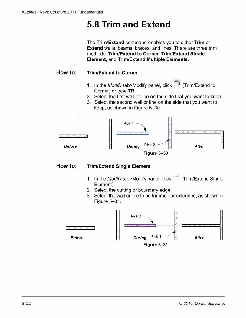
How to: Trim/Extend to Corner
1. In the Modify tab>Modify panel, click (Trim/Extend to Corner) or type TR.
2. Select the first wall or line on the side that you want to keep.3. Select the second wall or line on the side that you want to
keep, as shown in Figure 5–30.
Figure 5–30
How to: Trim/Extend Single Element
1. In the Modify tab>Modify panel, click (Trim/Extend Single Element).
2. Select the cutting or boundary edge.3. Select the wall or line to be trimmed or extended, as shown in
Figure 5–31.
Figure 5–31
Before During After
Before During After
Modify Commands
© 2010. Do not duplicate. 5–23
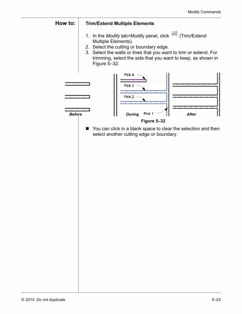
How to: Trim/Extend Multiple Elements
1. In the Modify tab>Modify panel, click (Trim/Extend Multiple Elements).
2. Select the cutting or boundary edge.3. Select the walls or lines that you want to trim or extend. For
trimming, select the side that you want to keep, as shown in Figure 5–32.
Figure 5–32
You can click in a blank space to clear the selection and then select another cutting edge or boundary.
Before During After
Autodesk Revit Structure 2011 Fundamentals
5–24 © 2010. Do not duplicate.
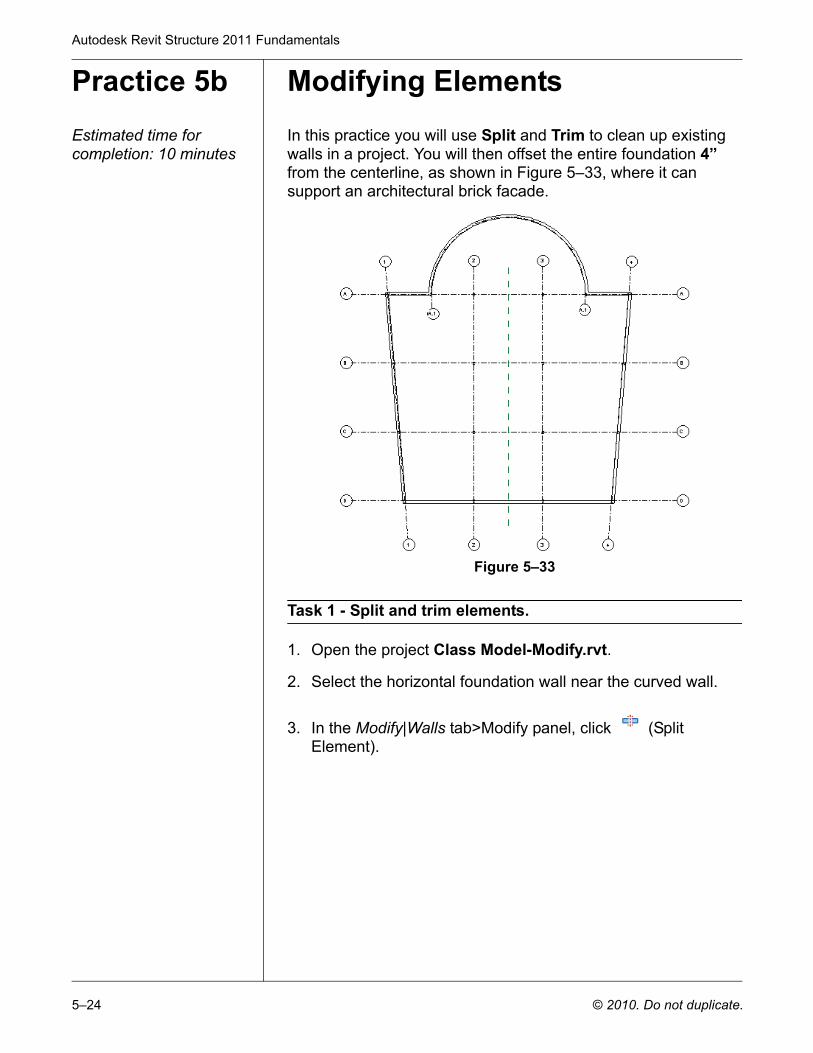
Practice 5b Modifying ElementsEstimated time for completion: 10 minutes
In this practice you will use Split and Trim to clean up existing walls in a project. You will then offset the entire foundation 4” from the centerline, as shown in Figure 5–33, where it can support an architectural brick facade.
Figure 5–33
Task 1 - Split and trim elements.
1. Open the project Class Model-Modify.rvt.
2. Select the horizontal foundation wall near the curved wall.
3. In the Modify|Walls tab>Modify panel, click (Split Element).
Modify Commands
© 2010. Do not duplicate. 5–25
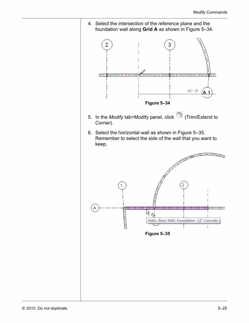
4. Select the intersection of the reference plane and the foundation wall along Grid A as shown in Figure 5–34.
Figure 5–34
5. In the Modify tab>Modify panel, click (Trim/Extend to Corner).
6. Select the horizontal wall as shown in Figure 5–35. Remember to select the side of the wall that you want to keep.
Figure 5–35
Autodesk Revit Structure 2011 Fundamentals
5–26 © 2010. Do not duplicate.
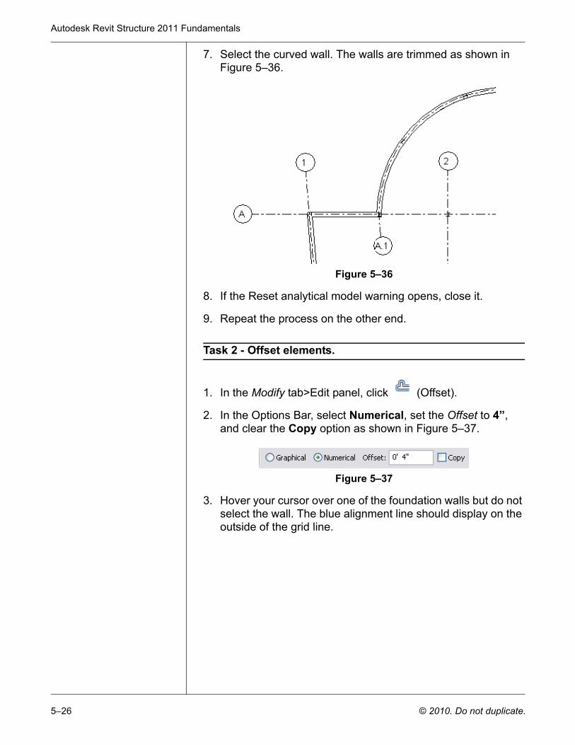
7. Select the curved wall. The walls are trimmed as shown in Figure 5–36.
Figure 5–36
8. If the Reset analytical model warning opens, close it.
9. Repeat the process on the other end.
Task 2 - Offset elements.
1. In the Modify tab>Edit panel, click (Offset).
2. In the Options Bar, select Numerical, set the Offset to 4”, and clear the Copy option as shown in Figure 5–37.
Figure 5–37
3. Hover your cursor over one of the foundation walls but do not select the wall. The blue alignment line should display on the outside of the grid line.
Modify Commands
© 2010. Do not duplicate. 5–27
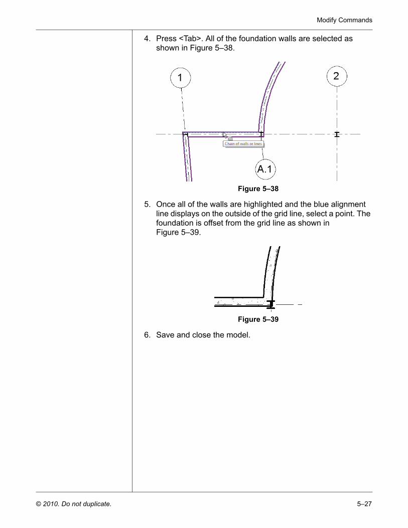
4. Press <Tab>. All of the foundation walls are selected as shown in Figure 5–38.
Figure 5–38
5. Once all of the walls are highlighted and the blue alignment line displays on the outside of the grid line, select a point. The foundation is offset from the grid line as shown in Figure 5–39.
Figure 5–39
6. Save and close the model.
Autodesk Revit Structure 2011 Fundamentals
5–28 © 2010. Do not duplicate.
Chapter Review Questions
1. While using the Move command, how can you change it to make a copy?
2. In the Array command, what is the difference between moving to second and moving to last?
3. How can you remove the middle segment during the Split command?
4. How do you change the center of rotation during the Rotate command?
Modify Commands
© 2010. Do not duplicate. 5–29
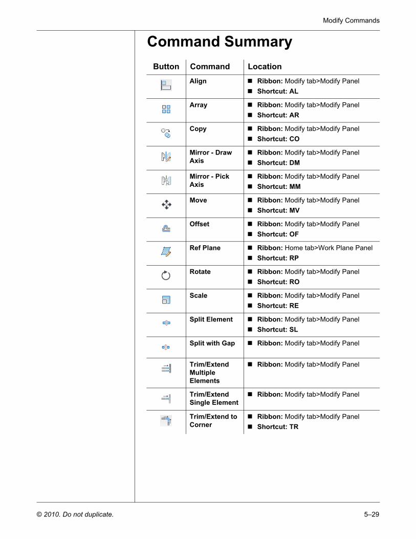
Command SummaryButton Command Location
Align Ribbon: Modify tab>Modify PanelShortcut: AL
Array Ribbon: Modify tab>Modify PanelShortcut: AR
Copy Ribbon: Modify tab>Modify PanelShortcut: CO
Mirror - Draw Axis
Ribbon: Modify tab>Modify PanelShortcut: DM
Mirror - Pick Axis
Ribbon: Modify tab>Modify PanelShortcut: MM
Move Ribbon: Modify tab>Modify PanelShortcut: MV
Offset Ribbon: Modify tab>Modify PanelShortcut: OF
Ref Plane Ribbon: Home tab>Work Plane PanelShortcut: RP
Rotate Ribbon: Modify tab>Modify PanelShortcut: RO
Scale Ribbon: Modify tab>Modify PanelShortcut: RE
Split Element Ribbon: Modify tab>Modify PanelShortcut: SL
Split with Gap Ribbon: Modify tab>Modify Panel
Trim/Extend Multiple Elements
Ribbon: Modify tab>Modify Panel
Trim/Extend Single Element
Ribbon: Modify tab>Modify Panel
Trim/Extend to Corner
Ribbon: Modify tab>Modify PanelShortcut: TR