Autodesk Revit 2008 - dscohn.com BIM-based Project Collaboration.pdfRevit connects the conceptual...
20
Autodesk Revit 2008 Working Together: BIM-based Project Collaboration David Cohn Course Summary: Collaboration between project teams can be overwhelming. Building project teams consist of architects, engineers, consultants, owners, and contractors. How do they all work together? This session looks at data exchange between members of the design/construction team. We’ll investigate how team members can collaborate using the entire family of Autodesk Revit software—Architecture, Structure, and MEP—as well as using other Autodesk software tools. Instructor: David has more than 20 years of hands-on experience with AutoCAD as a user, developer, author and consultant. He is an applications engineer and “Revit evangelist” with The PPI Group, a contributing editor to Desktop Engineering magazine, the former publisher and editor-in-chief of CADCAMNet and Engineering Automation Report, the former senior editor of CADalyst magazine, and the author of more than a dozen books on AutoCAD. A licensed architect, David was also one of the earliest AutoCAD third-party software developers, creating numerous AutoCAD add-on programs. As an industry consultant, David has worked with many companies including Autodesk. He teaches college-level AutoCAD courses and is always a popular presenter at Autodesk University. Autodesk User Group International www.AUGI.com
Transcript of Autodesk Revit 2008 - dscohn.com BIM-based Project Collaboration.pdfRevit connects the conceptual...

Autodesk Revit 2008 Working Together: BIM-based Project
Collaboration David Cohn
Course Summary: Collaboration between project teams can be overwhelming. Building project teams consist of architects, engineers, consultants, owners, and contractors. How do they all work together? This session looks at data exchange between members of the design/construction team. We’ll investigate how team members can collaborate using the entire family of Autodesk Revit software—Architecture, Structure, and MEP—as well as using other Autodesk software tools.
Instructor: David has more than 20 years of hands-on experience with AutoCAD as a user, developer, author and consultant. He is an applications engineer and “Revit evangelist” with The PPI Group, a contributing editor to Desktop Engineering magazine, the former publisher and editor-in-chief of CADCAMNet and Engineering Automation Report, the former senior editor of CADalyst magazine, and the author of more than a dozen books on AutoCAD. A licensed architect, David was also one of the earliest AutoCAD third-party software developers, creating numerous AutoCAD add-on programs. As an industry consultant, David has worked with many companies including Autodesk. He teaches college-level AutoCAD courses and is always a popular presenter at Autodesk University.
Autodesk User Group International www.AUGI.com

Introduction The building industry is perhaps the last to adopt the productivity advantages offered by technology. Manufacturing, agriculture, and finance have all embraced information technology. But while labor productivity in non-farm industries has almost doubled over the past 40 years, construction productivity has declined.
Labor productivity index for U.S. construction industry compared to all non-farm industries from 1964 through 2003.
Automotive, aerospace, electronics, and consumer goods manufacturers long ago adopted model-based digital design processes based on data that support energy analysis, bill-of-material generation, cost modeling, production planning, supply-chain integration, and even computer-driven fabrication. But the typical building project today is still produced in silos of design, fabrication, construction, and operation that consumes vast resources with huge inefficiency.
Part of the problem lies in the differences between manufacturing and building supply chains. Unlike the manufacturing world, building project teams may only work together once, and their end product is a single building that will be produced only once. And most of the methods of building project delivery are optimized for least cost and least exposure to each player in the process. Ultimately, building owners and operators bear the brunt of these inefficiencies in the form of construction errors, delays, and long-term operational and maintenance costs.
Computable Building Model While the construction industry has adopted digital tools such as CAD, most digital design data exists in a form that is not computable. For example, a word processor can be used to create rows and columns of financial data, but most of the numeric calculations and modifications must be done manually. The data is digital, but not very useful.
Autodesk User Group International
www.AUGI.com Copyright © AUGI CAD Camp 2007
2
Autodesk User Group International
www.AUGI.com Copyright © AUGI CAD Camp 2007
3
In contrast, a spreadsheet version of the same financial data might look identical to the word processor version, but the spreadsheet model contains numerical values, relationships, and sophisticated calculations. When a number changes, the rest of the spreadsheet updates automatically. The spreadsheet model is computable whereas the word processor representation is not, even though both are digital.
The building industry, for the most part, has adopted the word processor approach to documenting building designs over the past 20 years. CAD tools are used primarily to create electronic drawings of buildings. Even some 3D models are little more than 3D drawings. Although the CAD output may look like an accurate representation of the building—just as the financial table in the word processor looks the same as the spreadsheet table—it is not computable information.
It’s quite common to try to use this incomputable data for analysis, only to find that the data is simply a collection of graphic elements with no implicit knowledge of building elements. Humans must look at the data, interpret it, and transfer it to other applications for analysis.
Architects, engineers, designers, cost estimators, contractors, facilities managers, and others involved in the project all use purpose-built tools to gain a better understanding of their building projects—performing energy, structural and other design analyses; preparing cost estimates; scheduling construction processes. But using these tools often requires data to be manually entered into disparate systems, resulting in wasted time and effort as well as the potential for introducing errors. In addition, as the design changes and evolves, this data is no longer valid and must be re-entered.
Building Information Modeling Building information modeling (BIM) is an innovative new approach to building design, construction, and management that was introduced by Autodesk in 2002. Building information modeling is the creation and use of coordinated, consistent, computable information about a building project that yields reliable digital representations of the building—representations used for design decision-making, production of high-quality construction documents, performance predictions, cost-estimating and construction planning, and eventually, for managing and operating the facility.
While many technologies can be used to support BIM, Revit is purpose-built for BIM and delivers its highest benefits because it is based on a parametric building modeling technology, which uses a relational database together with a behavioral model to capture and present building information dynamically.
Autodesk offers three Revit-based products to address the needs of the entire building design team:
• Revit Architecture (formerly Revit Building)
• Revit Structure
• Revit MEP (formerly Revit Systems)
Autodesk User Group International
www.AUGI.com Copyright © AUGI CAD Camp 2007
4
All three are based on the same parametric change engine and use the same parametric building model. The Revit parametric building model is composed of project views (drawings and schedules), annotations (dimensions, section and detail keys, and so on), and building components (doors, windows, beams, columns, ducts, light fixtures) bound together into a single, integrated whole, ensuring that a change anywhere at any time is instantly reflected everywhere.
Views in all three versions of Revit are all “live” views of the model and are always up to date. There is no need to manually update or regenerate a view. Views recognize when they are placed on sheets and fill out their view tags accordingly.
Annotations are 2D, view-specific elements that help you produce your documentation. Annotation elements know how to size themselves on views of different scales and update when the scale of the view changes.
Just as a spreadsheet is a tool for thinking about numbers, software built on parametric building modeling technology is a tool for thinking about buildings. And just as a change made anywhere in a spreadsheet is expected to update everywhere with no further intervention from the user, so a change made anywhere in a parametric building model is immediately reflected everywhere.
Waste and inefficiency is a huge problem in the building construction industry, and is fundamentally unsustainable in both environmental and economic terms. The Economist reported in 2000 that inefficiencies, mistakes, and delays account for $200 billion of the $650 billion spent on construction in America every year; almost one-third of the total spending is lost to waste. 1
A large source of this waste and inefficiency is on-site rework required by poorly coordinated drawing sets. 2 Every change order that costs the owner or builder money but doesn’t add to the value of the building is wasted resources. Revit helps eliminate that waste by ensuring that the building information model—including the documentation—is always coordinated, consistent, and complete.
Conceptual Modeling The bulk of time spent on a design project is in the detailed design and construction document phases of a project, but the building’s general appearance and cost are largely fixed very early on, during conceptual design. Because the conceptual design is so crucial to the final building design, it would make sense to have a consistent flow of digital building information from beginning to end. However, the conceptual modeling tools and the detailed design tools are usually separate environments (unrelated software solutions), so the building models resulting from these two design stages have no digital association.
Revit connects the conceptual and detailed design stages with the Revit Building Maker, a conceptual design toolset within the Revit platform. With Revit Building Maker, the designer develops conceptual
1 “New Wiring,” The Economist, 1/13/2000 2 “Botched Plans,” Engineering News Record, 1/2000

models and maps them directly to building model components as the design progresses, all from within the Revit environment.
Building forms can be created from scratch using basic 3D shapes or generated from 2D profiles. You can also start out using your favorite 3D modeling software and then import ACIS solids or SketchUp files into Revit. Forms can be joined together or subtracted to create complex building geometry. Even at this early stage, designs can be validated by slicing the model up into floors and calculating gross floor areas and overall building volumes.
Revit Building Maker works like an architect thinks, seamlessly integrating the expressive and built form of a building design.
At any point, the designer can convert individual faces of these building masses to building model components such as walls, roofs, floors, curtain systems, and so on. Revit maintains the relationships between the conceptual model geometry and the building components so that changes to the conceptual model can ripple through to the detailed design model and even construction documents.
Working with Revit Architecture, Revit Structure, and Revit MEP Structural engineers using Revit Structure and working with architects using Revit Architecture can directly link to the Revit Architecture file to start their structural design. Similarly, MEP engineers using Revit MEP can link to architectural and structural Revit files. Sharing the same building information model with architects enables the structural, mechanical, electrical, plumbing and architectural design and documentation to stay coordinated.
Linking a Revit Architectural file with the Revit Structure model gives structural engineers a starting point for their design, based on the architect’s design intent. Changes made by the architect can be tracked, facilitating design coordination and change management. Similarly, architects using Revit
Autodesk User Group International
www.AUGI.com Copyright © AUGI CAD Camp 2007
5

Architecture can link a Revit Structure model into their architectural models and reap the same coordination benefits.
The same methodology works with Revit MEP. Revit MEP captures the functional relationships between building elements and systems. Walls, beams, ducts, pipes, and distribution panels all “know” what they are, what they do, and how to react to the rest of the building. For example, since the electrical and mechanical systems “know” about each other, an electrical engineer can track the power requirements of the mechanical equipment included in the design and have the software automatically configure electrical load requirements to dynamically change in response to changes in the mechanical equipment specifications.
Since all three Revit software solutions use the same underlying building database, the engineers can view, access, and query all the architectural properties of the model and architects can do the same for the structural and MEP elements.
Cross-linking architectural and structural models is the common method of sharing design models in Revit.
In addition to the BIM tools common to all the Revit products, Revit MEP features automatic sizing and systems layout tools, and provides engineers with immediate feedback on their design. For example, during the layout of a mechanical system, Revit MEP displays the critical flow of a mechanical system, allowing the engineer to modify the design for maximum performance and efficiency.
Autodesk User Group International
www.AUGI.com Copyright © AUGI CAD Camp 2007
6

The data-rich, computable Revit MEP model is used to drive the MEP design process, with a host of tools to aid in the layout of mechanical ductwork and piping, and plumbing systems. For example, Revit MEP enables users to perform many engineering calculations directly in the model; calculations like sizing mains, branches, or whole systems at a time, using industry-standard methods and specifications (such as the ASHRAE fitting loss database). System sizing tools are integrated with the layout tools and instantly update the size and design parameters of duct and pipe elements, without file exchanges or third-party applications.
Revit MEP enables duct sizing directly in the model during layout.
Revit MEP automatically provides duct and pipe routing solutions between any two points. The routing path is constrained by the engineer, who selects fitting or connection preferences to meet specific design criteria. The software then finds and displays multiple routing paths, allowing the engineer to choose the option that works best for a design.
During the layout of the plumbing design, a user can define the slope and the software automatically calculates invert elevations according to industry codes and tags them at the ends of pipe runs, minimizing the guesswork and manual calculation of sloped pipe. The software also automatically places all plumbing risers and drops, reducing the tedious aspects of system modeling.
When designing the mechanical systems, defining and understanding the physical relationships of building elements (size and location) is as important as understanding how the system functions (how much air flow can be delivered to a space and the pressure required to move that air through the ducts). For electronic design, however, wires aren’t actually routed in the model. The only things physically modeled are electrical devices and equipment such as lighting fixtures, transformers, generators, panel boxes, and so on. But system modeling is crucial. Are there any devices not assigned to a circuit? Is there adequate power and light for a space to be used as intended?
Autodesk User Group International
www.AUGI.com Copyright © AUGI CAD Camp 2007
7
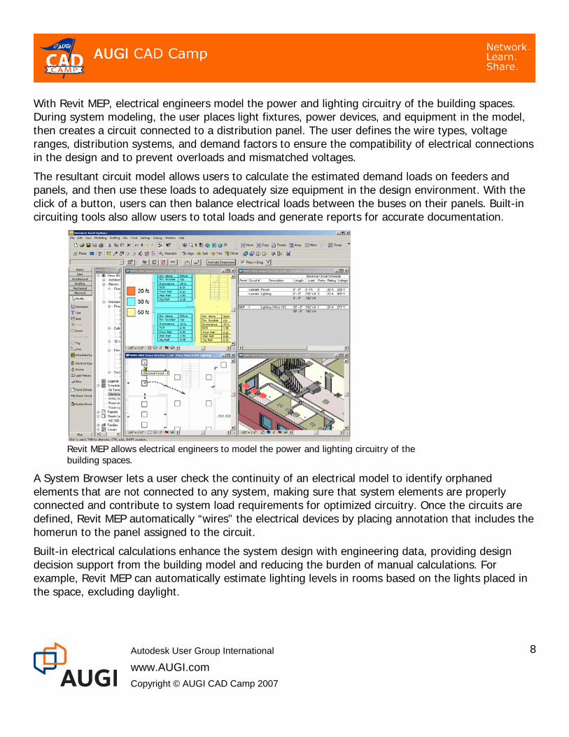
With Revit MEP, electrical engineers model the power and lighting circuitry of the building spaces. During system modeling, the user places light fixtures, power devices, and equipment in the model, then creates a circuit connected to a distribution panel. The user defines the wire types, voltage ranges, distribution systems, and demand factors to ensure the compatibility of electrical connections in the design and to prevent overloads and mismatched voltages.
The resultant circuit model allows users to calculate the estimated demand loads on feeders and panels, and then use these loads to adequately size equipment in the design environment. With the click of a button, users can then balance electrical loads between the buses on their panels. Built-in circuiting tools also allow users to total loads and generate reports for accurate documentation.
Revit MEP allows electrical engineers to model the power and lighting circuitry of the building spaces.
A System Browser lets a user check the continuity of an electrical model to identify orphaned elements that are not connected to any system, making sure that system elements are properly connected and contribute to system load requirements for optimized circuitry. Once the circuits are defined, Revit MEP automatically “wires” the electrical devices by placing annotation that includes the homerun to the panel assigned to the circuit.
Built-in electrical calculations enhance the system design with engineering data, providing design decision support from the building model and reducing the burden of manual calculations. For example, Revit MEP can automatically estimate lighting levels in rooms based on the lights placed in the space, excluding daylight.
Autodesk User Group International
www.AUGI.com Copyright © AUGI CAD Camp 2007
8
Linking Models Cross-linking the architectural, structural, and MEP models is the preferred means of sharing the models between architects and engineers if all are using Revit-based applications, but are in separate organizations without access to a shared network. They can exchange and cross-link their respective models, much like an architectural DWG file might be externally-referenced into a structural DWG file, but with far more intelligence.
Even when the engineers and architects are within the same A/E firm, linked files may still be the preferred way of working, because they develop their respective designs at a different pace and prefer the flexibility of keeping their own RVT files.
After linking, the engineer can reload new versions of the architectural model as needed to coordinate changes coming from the architect. Similarly, the architect can link the Revit Structure file to his model and then reload new versions when updates come from the structural engineer.
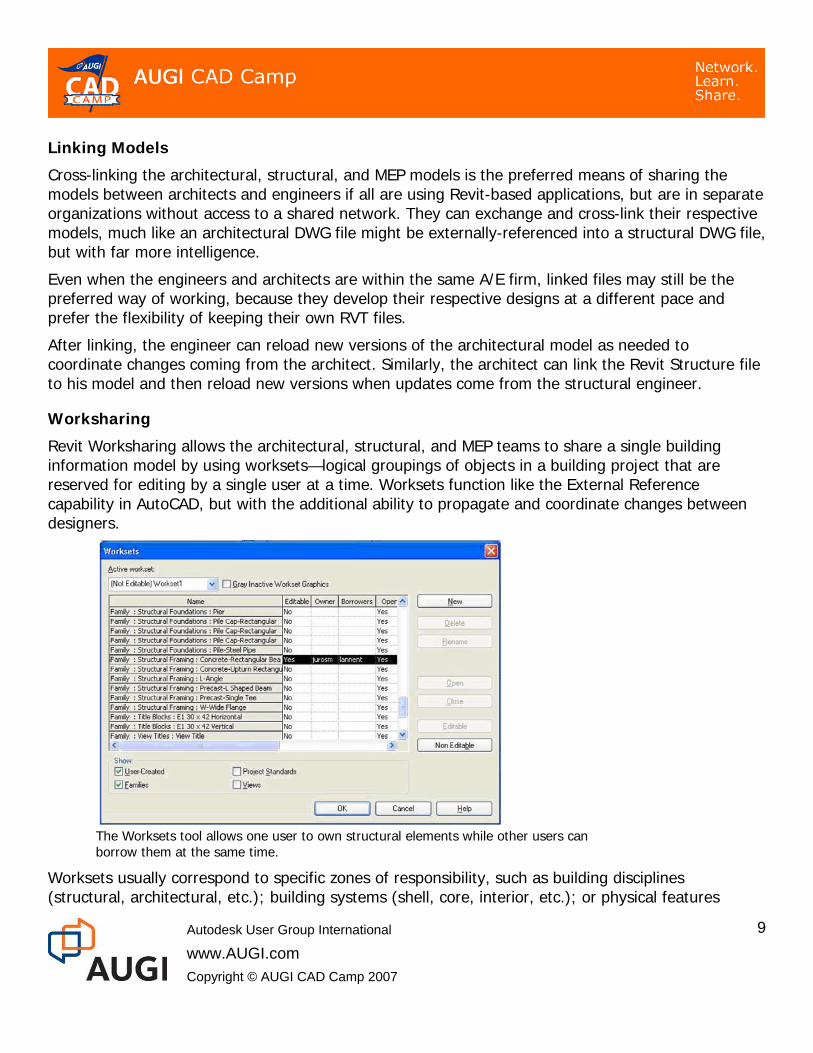
Worksharing Revit Worksharing allows the architectural, structural, and MEP teams to share a single building information model by using worksets—logical groupings of objects in a building project that are reserved for editing by a single user at a time. Worksets function like the External Reference capability in AutoCAD, but with the additional ability to propagate and coordinate changes between designers.
The Worksets tool allows one user to own structural elements while other users can borrow them at the same time.
Worksets usually correspond to specific zones of responsibility, such as building disciplines (structural, architectural, etc.); building systems (shell, core, interior, etc.); or physical features
Autodesk User Group International
www.AUGI.com Copyright © AUGI CAD Camp 2007
9

(levels, wings, etc.). Team members work on their own worksets, yet can see the latest changes from other team members. Team members can save their work to local files on their own hard drives and publish work periodically to the central file storage location so that other team members can see any changes. Team members retain ownership of their particular workset, yet other team members can borrow shared portions of a project model when needed, subject to permission being granted by the owner.
With a single shared model, Revit technology improves multi-discipline coordination while preserving responsibilities; structural elements remain the engineer’s responsibility and the architectural elements remain the architect’s responsibility.
Coordination Monitoring Revit also includes monitoring tools to ensure that model changes are coordinated. If the architect using Revit Architecture makes changes in the model to structural grids, levels, and columns, those changes are reflected in Revit Structure and the engineer using Revit Structure gets electronic notifications about the architect’s modifications. He then has the ability to reject, approve, or postpone those changes, depending on the impact that they might have on the structural integrity of the design. This same Coordination Review tool is also available to architects using Revit Architecture in order to check changes made by the engineers using Revit Structure and Revit MEP. The monitoring and coordination tool can be used for both linked and shared Revit model files.
Modifications made by the engineer or the architect on monitored elements can be reviewed in a convenient and accurate format.
Interference Checking Structural engineers using Revit Structure and architects using Revit Architecture can perform interference checks between architectural and structural objects (or just between structural objects,
Autodesk User Group International
www.AUGI.com Copyright © AUGI CAD Camp 2007
10

or between any model objects). This same interference checking tool also works with MEP elements, helping the MEP designer overcome the challenges of fitting the required components into tight spaces.
Interference checks can be performed on elements within the same file (such as a common RVT file shared between architects and engineers) or between the current structural or MEP file and a linked Revit Architecture file.
After selecting the elements to be analyzed and running the report, if any interference is detected, the report will indicate the exact location of the problem. The user can then select the element name in the Interference Report dialog box and click Show to view the interference condition in a 2D or 3D view. After making appropriate modifications to the model, the report can be refreshed to ensure that the interference condition no longer exists.
Interference checking can be performed between structural, MEP, and architectural objects. In this example, the resulting report shows that a structural column is interfering with a staircase.
Linking with Other Products Master builders once designed and built projects on-site. But as the centuries passed the processes that were used to create St. Peter’s Basilica and Notre Dame Cathedral evolved into what we now think of as the design/construction process, where architects and engineers—separated from the construction process—use two-dimensional drawings to visualize and document their design.
BIM allows architects and engineers to become “digital” master builders who are able to see the building, its materials, its structure, and its performance in real time as it is being designed, and
Autodesk User Group International
www.AUGI.com Copyright © AUGI CAD Camp 2007
11
(more importantly) before the design is converted into very expensive bricks and mortar. At the same time, this model can very effectively provide a fully coordinated set of conventional documents that is accurate and reliable.
The building information model can be used in conjunction with other software tools for energy analysis, lighting studies, and so forth, to quantify the project, while 3D visualizations and walk-throughs allow the design team and client to better understand the design.
Revit MEP can export to, import from, or link with a variety of CAD formats, including DWG, DWF, DXF, and DGN. This assures compatible data exchange with other software applications. For example, digital terrain models created in Autodesk Civil 3D can be imported and used to quickly add toposurfaces to the Revit building model.
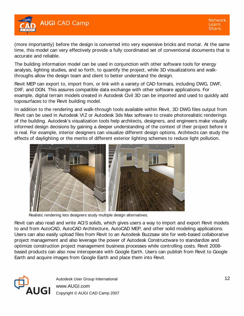
In addition to the rendering and walk-through tools available within Revit, 3D DWG files output from Revit can be used in Autodesk VIZ or Autodesk 3ds Max software to create photorealistic renderings of the building. Autodesk’s visualization tools help architects, designers, and engineers make visually informed design decisions by gaining a deeper understanding of the context of their project before it is real. For example, interior designers can visualize different design options. Architects can study the effects of daylighting or the merits of different exterior lighting schemes to reduce light pollution.
Realistic rendering lets designers study multiple design alternatives.
Revit can also read and write ACIS solids, which gives users a way to import and export Revit models to and from AutoCAD, AutoCAD Architecture, AutoCAD MEP, and other solid modeling applications. Users can also easily upload files from Revit to an Autodesk Buzzsaw site for web-based collaborative project management and also leverage the power of Autodesk Constructware to standardize and optimize construction project management business processes while controlling costs. Revit 2008-based products can also now interoperate with Google Earth. Users can publish from Revit to Google Earth and acquire images from Google Earth and place them into Revit.
Autodesk User Group International
www.AUGI.com Copyright © AUGI CAD Camp 2007
12

Autodesk User Group International
www.AUGI.com Copyright © AUGI CAD Camp 2007
13
Sustainable Design In the United States, commercial and residential buildings consume close to 40% of our total energy, 70% of our electricity, 40% of our raw materials, and 12% of fresh water supplies. They account for 30% of greenhouse gas emissions and generate 136 million tons of construction and demolition waste (approx. 2.8 lbs/person/day). 3
Sustainable design seeks to mitigate this negative impact through the use of environmentally sensitive design and construction practices. The goal of sustainable design is to produce green buildings that are “environmentally responsible, profitable, and healthy places to live and work.” 4
In the United States, the LEED standard has been adopted nationwide by federal agencies, state and local governments, and interested private companies as the guideline for sustainable building. A high LEED rating (out of a 69 point theoretical maximum) recognizes the excellence of a green building design and qualifies the project for an array of financial and regulatory incentives from state and local governments and even from privately funded organizations promoting sustainable design.
The Revit parametric building modeler represents the building as an integrated database of coordinated information. Beyond graphically depicting the design, much of the data needed for supporting sustainable design is captured naturally as the design of a project proceeds.
Calculations for LEED credits can be embedded in a schedule directly in the building information model and maintained dynamically as the project moves forward through design.
Sophisticated energy analysis is critical to a building design strategy for reduced energy consumption. Energy analysis programs have been available for years, but rarely used by design firms. Many firms outsource energy analysis (due to time and cost), and as a result building energy performance information is available only at fixed points in the project, usually later than needed for supporting the best decision-making about the project.
The Green Building XML (gbXML) protocol supported by Revit lets users extract engineering design data in a standard file format for interoperability with third-party applications, eliminating the error-prone and time consuming task of transferring data manually for load and sizing analyses.
For example, you can link Revit to the Green Building Studio (GBS) service from GeoPraxis (www.geopraxis.com) to provide reasonable, highly accurate, energy use estimates for the building you are designing. Model input files can also be used with engineering analysis systems such as eQUEST, EnergyPlus, or Trane Trace 700 for detailed analysis. The automated input can save hundreds of hours of manual labor.
3 U.S. Despartment of Energy, Energy Efficiency and Renewable Energy Network (EREN). Center of Excellence for Sustainable Development, 2003 4 U.S. Green Building Council, Mission Statement, 2004

Green Building Studio web service utilizing better building information from Revit allows architects to perform faster and more accurate energy analysis on early stage building designs.
Autodesk has also partnered with Integrated Environmental Solutions (IES) to provide analysis tools integrated directly inside the Revit environment. Revit MEP 2008 now includes the IES Virtual Environment, to provide reportable building analysis data at any stage in the design process. The IES tools enable users to study annual energy requirements, whole building carbon emission output, occupant satisfaction, and day-lighting and thermal analysis. Resulting reports are stored right inside the Revit building information model.
Cost Estimating When preparing their cost estimates, estimators typically begin by digitizing the architect’s paper drawings, or importing their CAD drawings into a cost estimating package, or doing manual takeoffs from their drawings. All of these methods introduce the potential for human error and propagate any inaccuracies that may exist in the original drawings.
By using a building information model instead of drawings, the takeoffs, counts, and measurements can be generated directly from the underlying model. Therefore the information is always consistent with the design. And when a change is made in the design, the change automatically ripples to all related construction documentation and schedules, as well as all the takeoffs, counts, and measurements that are used by the estimator.
The time spent by the estimator on quantification varies by project, but perhaps 50-80% of the time needed to create a cost estimate is spent just on quantification. Given those numbers, one can instantly appreciate the huge advantage of using a building information model for cost estimating.
Autodesk User Group International
www.AUGI.com Copyright © AUGI CAD Camp 2007
14

There are several different paths one can take to get quantities and material definitions out of a building information model and into a cost estimating program:
• Application Programming Interface (API) This method creates a direct link between the costing system and Revit (similar to the link between Revit and the IES Virtual Environment). From within Revit, the user exports the building model using the costing program’s data format and sends it to the estimator, who then opens it with the costing solution to begin the costing procress. This is the approach used by programs such as U.S. COST and Innovaya (which then inegrates with Sage Timberline Office Estimating).
• ODBC connection This approach uses the ODBC export function in Revit to integrate cost estimating software with the building information model, so that the cost estimating software can link counts, attributes, and geometry from the building model with cost and pricing information. Programs such as CostX (Australia) and ITALSOFT (Italy) use this approach.
• Output to Excel This method lets users create material takeoffs in Revit and simply output the data to a spreadsheet, which is then used as input for costing.
The API integration between Revit and U.S. COST allows users to develop cost estimates based directly on the building information model.
Tapping into BIM for Specifications Communicating the materials needed for a project—particularly important when specifying the materials needed for a green project—is another stumbling block because material specifications are usually created in isolation from the design model, so their development and upkeep are time-consuming and error-prone.
Autodesk User Group International
www.AUGI.com Copyright © AUGI CAD Camp 2007
15
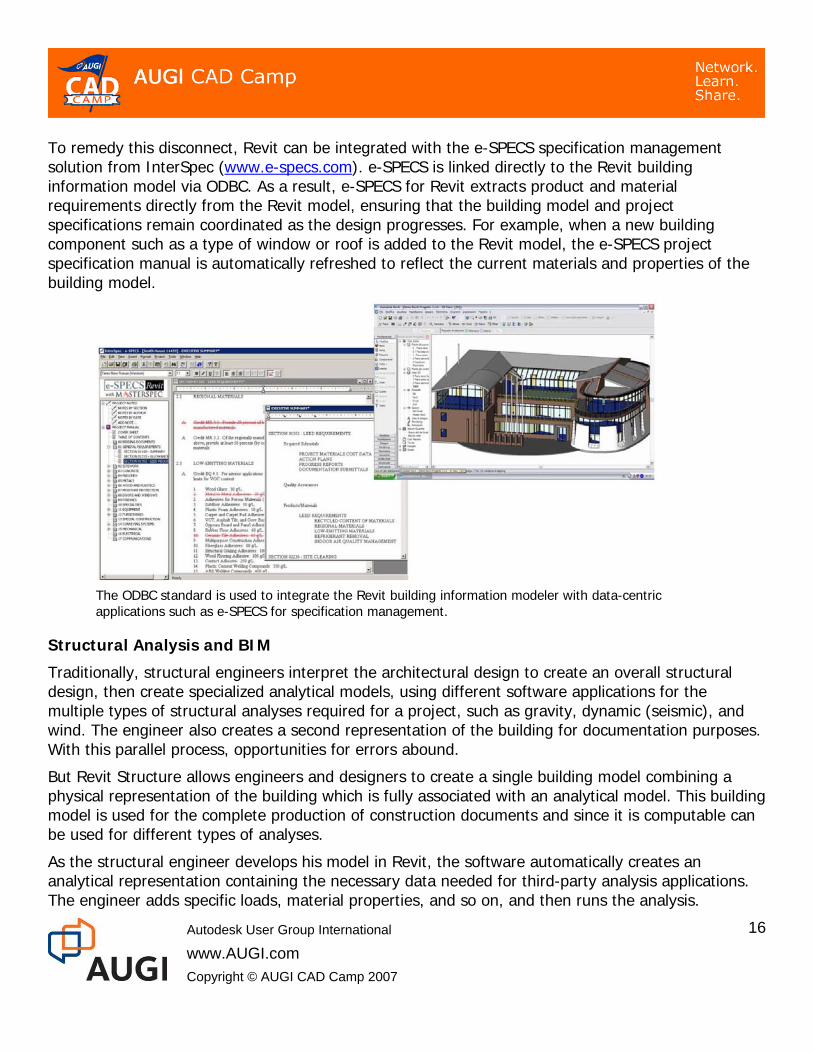
To remedy this disconnect, Revit can be integrated with the e-SPECS specification management solution from InterSpec (www.e-specs.com). e-SPECS is linked directly to the Revit building information model via ODBC. As a result, e-SPECS for Revit extracts product and material requirements directly from the Revit model, ensuring that the building model and project specifications remain coordinated as the design progresses. For example, when a new building component such as a type of window or roof is added to the Revit model, the e-SPECS project specification manual is automatically refreshed to reflect the current materials and properties of the building model.
The ODBC standard is used to integrate the Revit building information modeler with data-centric applications such as e-SPECS for specification management.
Structural Analysis and BIM Traditionally, structural engineers interpret the architectural design to create an overall structural design, then create specialized analytical models, using different software applications for the multiple types of structural analyses required for a project, such as gravity, dynamic (seismic), and wind. The engineer also creates a second representation of the building for documentation purposes. With this parallel process, opportunities for errors abound.
But Revit Structure allows engineers and designers to create a single building model combining a physical representation of the building which is fully associated with an analytical model. This building model is used for the complete production of construction documents and since it is computable can be used for different types of analyses.
As the structural engineer develops his model in Revit, the software automatically creates an analytical representation containing the necessary data needed for third-party analysis applications. The engineer adds specific loads, material properties, and so on, and then runs the analysis.
Autodesk User Group International
www.AUGI.com Copyright © AUGI CAD Camp 2007
16
If the engineer chooses to, the analysis program can then return information that dynamically updates the building model, eliminating much of the redundant work done by structural engineers to model and analyze building frames using many different applications.
Revit Structure doesn’t replace the analysis applications; it provides a common modeling interface to them and a common model to document the results. Using the Revit API, data moves directly from the Revit Structure building information model to the analysis software, and the analysis results are delivered back into the model, keeping analysis, design, and documentation all synchronized.
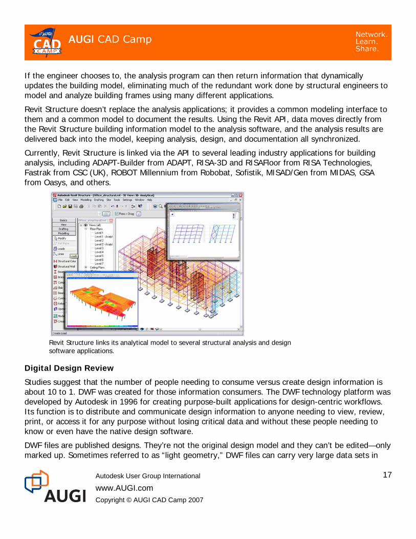
Currently, Revit Structure is linked via the API to several leading industry applications for building analysis, including ADAPT-Builder from ADAPT, RISA-3D and RISAFloor from RISA Technologies, Fastrak from CSC (UK), ROBOT Millennium from Robobat, Sofistik, MISAD/Gen from MIDAS, GSA from Oasys, and others.
Revit Structure links its analytical model to several structural analysis and design software applications.
Digital Design Review Studies suggest that the number of people needing to consume versus create design information is about 10 to 1. DWF was created for those information consumers. The DWF technology platform was developed by Autodesk in 1996 for creating purpose-built applications for design-centric workflows. Its function is to distribute and communicate design information to anyone needing to view, review, print, or access it for any purpose without losing critical data and without these people needing to know or even have the native design software.
DWF files are published designs. They’re not the original design model and they can’t be edited—only marked up. Sometimes referred to as “light geometry,” DWF files can carry very large data sets in
Autodesk User Group International
www.AUGI.com Copyright © AUGI CAD Camp 2007
17
Autodesk User Group International
www.AUGI.com Copyright © AUGI CAD Camp 2007
18
compressed format. A gigabyte-sized design file can be compressed to a DWF file that’s small enough to email, making the Internet a viable replacement for overnight mail or couriers.
The ability to publish to the DWF file specification is embedded in all Autodesk design applications, including the Revit software platform. Unlike image formats (such as TIFF or JPEG), which are just 2D images, or even 3D formats like Adobe Acrobat 3D, which only capture visual aspects of the model and don’t include the rich set of metadata, DWF retains both the 3D model geometry and the intelligent design data of the original design model. For example, properties of a door—such as its size, fire rating, frame material, and hardware set—can be included in the DWF file. In this way, DWF files can even be used to transmit information to other applications, such as facilities management or cost estimating, without any information being lost along the way.
DWF is at the core of Autodesk Design Review (formerly Autodesk DWF Composer), a completely digital way for a design team to review, mark up, and track changes to sheet sets and building models.
Autodesk Design Review facilitates electronic review cycles by taking the building information model published to digital DWF files from Revit and tracking redlines to those DWF files. By minimizing paper, reviewers can reduce errors and minimize the risk of using inaccurate or out-of-date information during the review process.
Autodesk Design Review allows reviewers to measure and mark up the design (as published in the DWF), making their comments and notes in the context of the design. The software automatically keeps track of all markups. The DWF format preserves all markup information, so comments or changes noted during the design review phase can be imported and tracked directly in Revit, enabling round-trip design review.
Facilities Management A 2004 NIST study estimated the annual cost (in 2002) in commercial, institutional, and industrial facilities associated with inadequate interoperability among computer-aided design, engineering, and software systems at $15.8 billion. 5 The study went on to report that owners and operators shoulder almost two thirds of that cost as a result of their ongoing facility operation and maintenance.
Owners and operators can mitigate their portion of the cost associated with the lack of interoperability by using the high-quality building information coming from a BIM design process during the longer, more expensive maintenance and operation phase of the building’s lifecycle. To that end, Autodesk has used DWF technology to link Revit and Autodesk’s FMDesktop software platform and products. FMDesktop reads DWF files published from Revit and automatically interprets space and room data, without the FMDesktop user’s needing to know or even have a Revit software product. Architects using Revit Architecture can simply publish their building information model to
5 Cost Analysis of Inadequate Interoperability in the U.S. Capital Facilities Industry, Gallaher, M.P.; O’Connor, A.C.; Dettbarn, J.L., Jr.; Gilday, L.T. (NIST GCR 04-867; 194p. August 2004)
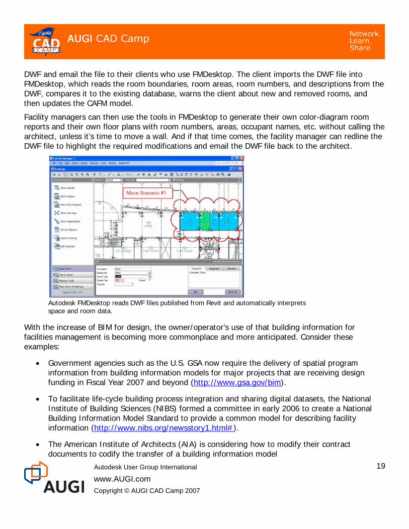
DWF and email the file to their clients who use FMDesktop. The client imports the DWF file into FMDesktop, which reads the room boundaries, room areas, room numbers, and descriptions from the DWF, compares it to the existing database, warns the client about new and removed rooms, and then updates the CAFM model.
Facility managers can then use the tools in FMDesktop to generate their own color-diagram room reports and their own floor plans with room numbers, areas, occupant names, etc. without calling the architect, unless it’s time to move a wall. And if that time comes, the facility manager can redline the DWF file to highlight the required modifications and email the DWF file back to the architect.
Autodesk FMDesktop reads DWF files published from Revit and automatically interprets space and room data.
With the increase of BIM for design, the owner/operator’s use of that building information for facilities management is becoming more commonplace and more anticipated. Consider these examples:
• Government agencies such as the U.S. GSA now require the delivery of spatial program information from building information models for major projects that are receiving design funding in Fiscal Year 2007 and beyond (http://www.gsa.gov/bim).
• To facilitate life-cycle building process integration and sharing digital datasets, the National Institute of Building Sciences (NIBS) formed a committee in early 2006 to create a National Building Information Model Standard to provide a common model for describing facility information (http://www.nibs.org/newsstory1.html#).
• The American Institute of Architects (AIA) is considering how to modify their contract documents to codify the transfer of a building information model
Autodesk User Group International
www.AUGI.com Copyright © AUGI CAD Camp 2007
19

Autodesk User Group International
www.AUGI.com Copyright © AUGI CAD Camp 2007
20
(http://www.aia.org/nwsltr_tap.cfm?pagename=tap_a_documents); putting in place an agreement structure whereby the building information model and the intellectual property it represents can flow naturally from the architect to the owner/operator, who can then get better data to manage a building from the most appropriate source of that data: the architect who designed the building.
Conclusions Building information modeling clearly provides the means to increase productivity and accuracy while reducing design cycle times. It enables reduction of waste and inefficiency and can lead to the development of a more sustainable environment, enable building fabrication from digital information, and help better manage buildings throughout their lifecycle. In order for this to happen, changes will be necessary, particularly in reallocating the risks and rewards inherent in the construction process. This change will likely be driven in equal parts by owners’ demands and designers’ recognition of the benefits of working from a computable building model. Undoubtedly, the tools will continue to evolve, but the tools are now readily available to facilitate complete BIM-based project collaboration.
As stated in the conclusion of a third-party Revit implementation study, “Those who have persevered in their learning and use of Revit have come to love the application and find it anathema to go back to traditional CAD. For them, the practice of architecture will never be the same again.” 6 Or, as Jeff Millett, AIA, Director of Information and Communications Technologies for The Stubbins Associates said, “It’s sad to see an architect drafting in CAD—such a waste of talent and energy.”
Additional References Autodesk has a number of whitepapers and other references available on its website. Much of the material in this paper comes from the following sources, which can be found by searching for their titles:
6 “Implementation in Practice” by Dr. Lachmi Khemlani
“Barriers to the Adoption of BIM in the Building Industry”
“BIM and Cost Estimating”
“BIM and DWF”
“BIM and Facilities Management”
“BIM Concept to Completion”
“BIM for Interior Design”
“BIM in Action”
“BIM – Small, Medium…Extra Large!”
“Building Information Modeling for Sustainable Design”
“Coordination Between Revit Structure and Revit Architecture”
“Effective Collaboration: Exporting ACIS Solids”
“Maintaining BIM Integrity in the Structural Engineering Office”
“Parametric Building Modeling: BIM’s Foundation”
“Revit MEP: BIM for MEP Engineering”
“Revit Structure and BIM”
“Tapping BIM Using ODBC”
“Transitioning to BIM”
“Using BIM for Greener Designs”