Autodesk Design Review 2013 Help
306
Autodesk Design Review 2013 Help January 2012
Transcript of Autodesk Design Review 2013 Help

Autodesk Design Review 2013
Help
January 2012

Legal Notices
Autodesk® Design Review 2013
© 2012 Autodesk, Inc. All Rights Reserved. Except as otherwise permitted by Autodesk, Inc., this publication, or parts thereof, may notbe reproduced in any form, by any method, for any purpose.
Certain materials included in this publication are reprinted with the permission of the copyright holder.
Third-Party Software Credits and Attributions
This software is based in part on the works of the following:
Copyright © 1995-2005 The OpenSSL Project. All rights reserved.
Redistributions and use in source and binary forms, with or without modification, are permitted provided that the following conditions are met:
1. Redistributions of source code must retain the above copyright notice, this list of conditions and the following disclaimer.
2. Redistributions in binary form must reproduce the above copyright notice, this list of conditions and the following disclaimer in thedocumentation and/or other materials provided with the distribution.
3. All advertising materials mentioning features or use of this software must display the following acknowledgment: "This product includessoftware developed by the OpenSSL Project for use in the OpenSSL Toolkit. (http://www.openssl.org/)"
4. The names "OpenSSL Toolkit" and "OpenSSL Project" must not be used to endorse or promote products derived from this software withoutprior written permission. For written permission, please contact [email protected].
5. Products derived from this software may not be called "OpenSSL" nor may "OpenSSL" appear in their names without prior written permissionof the OpenSSL Project.
6. Redistributions of any form whatsoever must retain the following acknowledgment: "This product includes software developed by the OpenSSLProject for use in the OpenSSL Toolkit (http://www.openssl.org/)"
THIS SOFTWARE IS PROVIDED BY THE OpenSSL PROJECT "AS IS'' AND ANY EXPRESSED OR IMPLIED WARRANTIES, INCLUDING, BUT NOTLIMITED TO, THE IMPLIED WARRANTIES OF MERCHANTABILITY AND FITNESS FOR A PARTICULAR PURPOSE ARE DISCLAIMED. IN NO EVENTSHALL THE OpenSSL PROJECT OR ITS CONTRIBUTORS BE LIABLE FOR ANY DIRECT, INDIRECT, INCIDENTAL, SPECIAL, EXEMPLARY, ORCONSEQUENTIAL DAMAGES (INCLUDING, BUT NOT LIMITED TO, PROCUREMENT OF SUBSTITUTE GOODS OR SERVICES; LOSS OF USE, DATA,OR PROFITS; OR BUSINESS INTERRUPTION) HOWEVER CAUSED AND ON ANY THEORY OF LIABILITY, WHETHER IN CONTRACT, STRICT LIABILITY,OR TORT (INCLUDING NEGLIGENCE OR OTHERWISE) ARISING IN ANY WAY OUT OF THE USE OF THIS SOFTWARE, EVEN IF ADVISED OF THEPOSSIBILITY OF SUCH DAMAGE.This product includes cryptographic software written by Eric Young ([email protected]). This product includessoftware written by Tim Hudson ([email protected]).
Copyright © 1995-1998 Eric Young ([email protected]) All rights reserved.
Redistribution and use in source and binary forms, with or without modification, are permitted provided that the following conditions are met:
1. Redistributions of source code must retain the copyright notice, this list of conditions and the following disclaimer.
2. Redistributions in binary form must reproduce the above copyright notice, this list of conditions and the following disclaimer in thedocumentation and/or other materials provided with the distribution.
3. All advertising materials mentioning features or use of this software must display the following acknowledgement: “This product includescryptographic software written by Eric Young ([email protected])” The word ‘cryptographic’ can be left out if the routines from the librarybeing used are not cryptographic related :-).
4. If you include any Windows specific code (or a derivative thereof) from the apps directory (application code) you must include anacknowledgement:
“This product includes software written by Tim Hudson ([email protected])” THIS SOFTWARE IS PROVIDED BY ERIC YOUNG “AS IS” AND ANYEXPRESS OR IMPLIED WARRANTIES, INCLUDING, BUT NOT LIMITED TO, THE IMPLIED WARRANTIES OF MERCHANTABILITY AND FITNESS FORA PARTICULAR PURPOSE ARE DISCLAIMED. IN NO EVENT SHALL THE AUTHOR OR CONTRIBUTORS BE LIABLE FOR ANY DIRECT, INDIRECT,INCIDENTAL, SPECIAL, EXEMPLARY, OR CONSEQUENTIAL DAMAGES (INCLUDING, BUT NOT LIMITED TO, PROCUREMENT OF SUBSTITUTEGOODS OR SERVICES; LOSS OF USE, DATA, OR PROFITS; OR BUSINESS INTERRUPTION) HOWEVER CAUSED AND ON ANY THEORY OF LIABILITY,WHETHER IN CONTRACT, STRICT LIABILITY, OR TORT (INCLUDING NEGLIGENCE OR OTHERWISE) ARISING IN ANY WAY OUT OF THE USE OFTHIS SOFTWARE, EVEN IF ADVISED OF THE POSSIBILITY OF SUCH DAMAGE. The license and distribution terms for any publicly available versionor derivative of this code cannot be changed, i.e., this code cannot simply be copied and put under another distribution license [including theGNU Public License].
LibTiff (http://www.libtiff.org), Copyright © 1988-1997 Sam Leffler, Copyright © 1991-1997 Silicon Graphics, Inc., under the following license:
Permission to use, copy, modify, distribute, and sell this libtiff software and its documentation for any purpose is hereby granted without fee,provided that (i) the above copyright notices and this permission notice appear in all copies of the software and related documentation, and(ii) the names of Sam Leffler and Silicon Graphics may not be used in any advertising or publicity relating to the software without the specific,prior written permission of Sam Leffler and Silicon Graphics.

THE SOFTWARE IS PROVIDED "AS-IS" AND WITHOUT WARRANTY OF ANY KIND, EXPRESS, IMPLIED OR OTHERWISE, INCLUDING WITHOUTLIMITATION, ANY WARRANTY OF MERCHANTABILITY OR FITNESS FOR A PARTICULAR PURPOSE.
IN NO EVENT SHALL SAM LEFFLER OR SILICON GRAPHICS BE LIABLE FOR ANY SPECIAL, INCIDENTAL, INDIRECT OR CONSEQUENTIAL DAMAGESOF ANY KIND, OR ANY DAMAGES WHATSOEVER RESULTING FROM LOSS OF USE, DATA OR PROFITS, WHETHER OR NOT ADVISED OF THEPOSSIBILITY OF DAMAGE, AND ON ANY THEORY OF LIABILITY, ARISING OUT OF OR IN CONNECTION WITH THE USE OR PERFORMANCE OFTHIS SOFTWARE.
This software is based in part on the work of the Independent JPEG Group.
PDF technology powered by PDFNet SDk copyright © PDFTron™ Systems Inc., 2001-2008, and distributed by Autodesk, Inc, under license. Allrights reserved.
Copyright © 1998, 1999, 2000 Thai Open Source Software Center Ltd.
Permission is hereby granted, free of charge, to any person obtaining a copy of this software and associated documentation files (the "Software"),to deal in the Software without restriction, including without limitation the rights to use, copy, modify, merge, publish, distribute, sublicense,and/or sell copies of the Software, and to permit persons to whom the Software is furnished to do so, subject to the following conditions:
THE SOFTWARE IS PROVIDED "AS IS", WITHOUT WARRANTY OF ANY KIND, EXPRESS OR IMPLIED, INCLUDING BUT NOT LIMITED TO THEWARRANTIES OF MERCHANTABILITY, FITNESS FOR A PARTICULAR PURPOSE AND NONINFRINGEMENT.IN NO EVENT SHALL THE AUTHORSOR COPYRIGHT HOLDERS BE LIABLE FOR ANY CLAIM, DAMAGES OR OTHER LIABILITY, WHETHER IN AN ACTION OF CONTRACT, TORT OROTHERWISE, ARISING FROM, OUT OF OR IN CONNECTION WITH THE SOFTWARE OR THE USE OR OTHER DEALINGS IN THE SOFTWARE.
Trademarks
The following are registered trademarks or trademarks of Autodesk, Inc., and/or its subsidiaries and/or affiliates in the USA and other countries:123D, 3ds Max, Algor, Alias, Alias (swirl design/logo), AliasStudio, ATC, AUGI, AutoCAD, AutoCAD Learning Assistance, AutoCAD LT, AutoCADSimulator, AutoCAD SQL Extension, AutoCAD SQL Interface, Autodesk, Autodesk Homestyler, Autodesk Intent, Autodesk Inventor, AutodeskMapGuide, Autodesk Streamline, AutoLISP, AutoSketch, AutoSnap, AutoTrack, Backburner, Backdraft, Beast, Beast (design/logo) Built withObjectARX (design/logo), Burn, Buzzsaw, CAiCE, CFdesign, Civil 3D, Cleaner, Cleaner Central, ClearScale, Colour Warper, Combustion,Communication Specification, Constructware, Content Explorer, Creative Bridge, Dancing Baby (image), DesignCenter, Design Doctor, Designer'sToolkit, DesignKids, DesignProf, DesignServer, DesignStudio, Design Web Format, Discreet, DWF, DWG, DWG (design/logo), DWG Extreme,DWG TrueConvert, DWG TrueView, DWFX, DXF, Ecotect, Evolver, Exposure, Extending the Design Team, Face Robot, FBX, Fempro, Fire, Flame,Flare, Flint, FMDesktop, Freewheel, GDX Driver, Green Building Studio, Heads-up Design, Heidi, Homestyler, HumanIK, IDEA Server, i-drop,Illuminate Labs AB (design/logo), ImageModeler, iMOUT, Incinerator, Inferno, Instructables, Instructables (stylized robot design/logo),Inventor,Inventor LT, Kynapse, Kynogon, LandXplorer, LiquidLight, LiquidLight (design/logo), Lustre, MatchMover, Maya, Mechanical Desktop, Moldflow,Moldflow Plastics Advisers, Moldflow Plastics Insight, Moldflow Plastics Xpert, Moondust, MotionBuilder, Movimento, MPA, MPA (design/logo),MPI, MPI (design/logo), MPX, MPX (design/logo), Mudbox, Multi-Master Editing, Navisworks, ObjectARX, ObjectDBX, Opticore, Pipeplus, Pixlr,Pixlr-o-matic, PolarSnap, PortfolioWall, Powered with Autodesk Technology, Productstream, ProMaterials, RasterDWG, RealDWG, Real-timeRoto, Recognize, Render Queue, Retimer, Reveal, Revit, RiverCAD, Robot, Scaleform, Scaleform GFx, Showcase, Show Me, ShowMotion,SketchBook, Smoke, Softimage, Softimage|XSI (design/logo), Sparks, SteeringWheels, Stitcher, Stone, StormNET, Tinkerbox, ToolClip, Topobase,Toxik, TrustedDWG, U-Vis, ViewCube, Visual, Visual LISP, Voice Reality, Volo, Vtour, WaterNetworks, Wire, Wiretap, WiretapCentral, XSI.
HP Instant Printing is a registered Trademark of Hewlett-Packard Company.
All other brand names, product names or trademarks belong to their respective holders.
Disclaimer
THIS PUBLICATION AND THE INFORMATION CONTAINED HEREIN IS MADE AVAILABLE BY AUTODESK, INC. "AS IS." AUTODESK, INC. DISCLAIMSALL WARRANTIES, EITHER EXPRESS OR IMPLIED, INCLUDING BUT NOT LIMITED TO ANY IMPLIED WARRANTIES OF MERCHANTABILITY ORFITNESS FOR A PARTICULAR PURPOSE REGARDING THESE MATERIALS.


Contents
Chapter 1 Getting Started . . . . . . . . . . . . . . . . . . . . . . . . . . . 1About Design Review . . . . . . . . . . . . . . . . . . . . . . . . . . . . 1What's New in Design Review 2013? . . . . . . . . . . . . . . . . . . . . 3Get Help with Design Review . . . . . . . . . . . . . . . . . . . . . . . 4
Get Help with Design Review . . . . . . . . . . . . . . . . . . . . 4Join the Customer Involvement Program . . . . . . . . . . . . . . . . . 6
Join the Customer Involvement Program . . . . . . . . . . . . . . 6System Requirements . . . . . . . . . . . . . . . . . . . . . . . . . . . . 7
Chapter 2 Tour Design Review . . . . . . . . . . . . . . . . . . . . . . . . . 9About the Application Window . . . . . . . . . . . . . . . . . . . . . . 9About the Application Button . . . . . . . . . . . . . . . . . . . . . . 11Use the Quick Access Toolbar . . . . . . . . . . . . . . . . . . . . . . . 13
Use the Quick Access Toolbar . . . . . . . . . . . . . . . . . . . . 13Use the Ribbon . . . . . . . . . . . . . . . . . . . . . . . . . . . . . . 14
Use the Ribbon . . . . . . . . . . . . . . . . . . . . . . . . . . . 16Use the Canvas Toolbar . . . . . . . . . . . . . . . . . . . . . . . . . . 17Use Palettes . . . . . . . . . . . . . . . . . . . . . . . . . . . . . . . . 19
Manipulate Palettes . . . . . . . . . . . . . . . . . . . . . . . . . 19Manipulate Palettes . . . . . . . . . . . . . . . . . . . . . . 22
Thumbnails Palette . . . . . . . . . . . . . . . . . . . . . . . . . 24Thumbnails Palette . . . . . . . . . . . . . . . . . . . . . . 24
List View Palette . . . . . . . . . . . . . . . . . . . . . . . . . . . 25
v

List View Palette . . . . . . . . . . . . . . . . . . . . . . . . 26Sheet Properties Palette . . . . . . . . . . . . . . . . . . . . . . . 26
Sheet Properties Palette . . . . . . . . . . . . . . . . . . . . 26Markup Properties Palette . . . . . . . . . . . . . . . . . . . . . . 27
Markup Properties Palette . . . . . . . . . . . . . . . . . . . 27Object Properties Palette . . . . . . . . . . . . . . . . . . . . . . 28
Object Properties Palette . . . . . . . . . . . . . . . . . . . 28Markups Palette . . . . . . . . . . . . . . . . . . . . . . . . . . . 29Model Palette . . . . . . . . . . . . . . . . . . . . . . . . . . . . 30
Model Palette . . . . . . . . . . . . . . . . . . . . . . . . . 31Views Palette . . . . . . . . . . . . . . . . . . . . . . . . . . . . 31
Views Palette . . . . . . . . . . . . . . . . . . . . . . . . . 32Cross Sections Palette . . . . . . . . . . . . . . . . . . . . . . . . 34
Cross Sections Palette . . . . . . . . . . . . . . . . . . . . . 34Layers Palette . . . . . . . . . . . . . . . . . . . . . . . . . . . . 35
Layers Palette . . . . . . . . . . . . . . . . . . . . . . . . . 35Text Data Palette . . . . . . . . . . . . . . . . . . . . . . . . . . 36
Text Data Palette . . . . . . . . . . . . . . . . . . . . . . . 36Grid Data Palette . . . . . . . . . . . . . . . . . . . . . . . . . . 37
Grid Data Palette . . . . . . . . . . . . . . . . . . . . . . . 37Find Palette . . . . . . . . . . . . . . . . . . . . . . . . . . . . . 37
Find Palette . . . . . . . . . . . . . . . . . . . . . . . . . . 37Use Workspaces . . . . . . . . . . . . . . . . . . . . . . . . . . . . . . 38
Use Workspaces . . . . . . . . . . . . . . . . . . . . . . . . . . . 39
Chapter 3 Using Design Review . . . . . . . . . . . . . . . . . . . . . . . 43Receive DWF Files . . . . . . . . . . . . . . . . . . . . . . . . . . . . . 43
About Receiving DWF Files . . . . . . . . . . . . . . . . . . . . . 43Open Files . . . . . . . . . . . . . . . . . . . . . . . . . . . . . . . . . 44
About Disabled DWF Files . . . . . . . . . . . . . . . . . . . . . 44About Opening Other File Types . . . . . . . . . . . . . . . . . . 45About Opening Multiple Files . . . . . . . . . . . . . . . . . . . . 49Open a File . . . . . . . . . . . . . . . . . . . . . . . . . . . . . 50
Open a File . . . . . . . . . . . . . . . . . . . . . . . . . . 50Open a DWF File from Buzzsaw . . . . . . . . . . . . . . . . . . . 52
Open a DWF File from Buzzsaw . . . . . . . . . . . . . . . 52Locate DWF-Related Content . . . . . . . . . . . . . . . . . . . . . . . 53
Find Text in an Open DWF File . . . . . . . . . . . . . . . . . . . 53Find Text in an Open DWF File . . . . . . . . . . . . . . . . 54
Search Autodesk Seek . . . . . . . . . . . . . . . . . . . . . . . . 54Search Autodesk Seek . . . . . . . . . . . . . . . . . . . . . 55
Use Published Hyperlinks . . . . . . . . . . . . . . . . . . . . . . 55Use Published Hyperlinks . . . . . . . . . . . . . . . . . . . 56
View DWF Files . . . . . . . . . . . . . . . . . . . . . . . . . . . . . . 57Change 2D Sheet Views . . . . . . . . . . . . . . . . . . . . . . . 57
View a DWF File in Grayscale or Black and White . . . . . . 57
vi | Contents
Pan and Zoom the View of the Canvas . . . . . . . . . . . . 57Use the 2D Navigation Wheel . . . . . . . . . . . . . . . . 60Reset the View . . . . . . . . . . . . . . . . . . . . . . . . . 61Rotate 2D Sheets . . . . . . . . . . . . . . . . . . . . . . . 62
Change 3D Model Views . . . . . . . . . . . . . . . . . . . . . . 63About 3D DWF Files . . . . . . . . . . . . . . . . . . . . . . 63Use Standard 3D Model Views . . . . . . . . . . . . . . . . 64Change the Field of View . . . . . . . . . . . . . . . . . . . 66Orbit the View Around a 3D Model . . . . . . . . . . . . . 69Spin the View of a 3D Model . . . . . . . . . . . . . . . . . 71Use the ViewCube . . . . . . . . . . . . . . . . . . . . . . 72Use the 3D SteeringWheels . . . . . . . . . . . . . . . . . . 77
Control the Appearance of 3D Objects . . . . . . . . . . . . . . . 90Change the Visibility of Objects and Subobjects . . . . . . . 90Control Lighting Effects for 3D Objects . . . . . . . . . . . 91Shade 3D Objects . . . . . . . . . . . . . . . . . . . . . . . 93View Shadows for 3D Objects . . . . . . . . . . . . . . . . . 94
Pull Apart 3D Models . . . . . . . . . . . . . . . . . . . . . . . . 95Move and Rotate 3D Objects . . . . . . . . . . . . . . . . . 95Reset 3D Objects . . . . . . . . . . . . . . . . . . . . . . . 99
View Cross Sections of a 3D Model . . . . . . . . . . . . . . . . 100Cross Section 3D Models . . . . . . . . . . . . . . . . . . 100Move and Rotate Section Planes . . . . . . . . . . . . . . . 102Flip Cross Sections . . . . . . . . . . . . . . . . . . . . . . 104Hide or Show a Section Plane . . . . . . . . . . . . . . . . 105Control Cross Section Display . . . . . . . . . . . . . . . . 106Control Caps Display . . . . . . . . . . . . . . . . . . . . 107View a Cross Section Parallel to the Screen . . . . . . . . . 107Rename a Cross Section . . . . . . . . . . . . . . . . . . . 108Reset a Section Plane . . . . . . . . . . . . . . . . . . . . . 108Delete Cross Sections . . . . . . . . . . . . . . . . . . . . 108
View Animations in 3D DWF Files . . . . . . . . . . . . . . . . 109About Animations in DWF Files . . . . . . . . . . . . . . . 109About Animation Tools . . . . . . . . . . . . . . . . . . . 110Start an Animation . . . . . . . . . . . . . . . . . . . . . 112View Animations . . . . . . . . . . . . . . . . . . . . . . . 113Markup Animations . . . . . . . . . . . . . . . . . . . . . 115Take a Snapshot of an Animation . . . . . . . . . . . . . . 116Change How an Animation Is Displayed . . . . . . . . . . 116About Viewing Assembly Instructions . . . . . . . . . . . . 118
View Tabular Data . . . . . . . . . . . . . . . . . . . . . . . . . 119About Tabular Data . . . . . . . . . . . . . . . . . . . . . 119About Tables . . . . . . . . . . . . . . . . . . . . . . . . . 120View Tabular Data . . . . . . . . . . . . . . . . . . . . . . 121Markup Tabular Data . . . . . . . . . . . . . . . . . . . . 123Print Tabular Data . . . . . . . . . . . . . . . . . . . . . . 123
Contents | vii
View Georeferenced Maps . . . . . . . . . . . . . . . . . . . . . 124About Georeferenced Maps . . . . . . . . . . . . . . . . . 124About Map Tools . . . . . . . . . . . . . . . . . . . . . . . 125Use a Georeferenced Map . . . . . . . . . . . . . . . . . . 127
Publish DWF Files . . . . . . . . . . . . . . . . . . . . . . . . . . . . 130About Publishing Non-DWF Files . . . . . . . . . . . . . . . . . 130Publish a New DWF File from Windows Explorer . . . . . . . . . 131
Publish a New DWF File from Windows Explorer . . . . . . 131Get Design Review Add-ins . . . . . . . . . . . . . . . . . . . . 132
Compose DWF Files . . . . . . . . . . . . . . . . . . . . . . . . . . . 133About Composing DWF Files . . . . . . . . . . . . . . . . . . . 133Combine DWF Files . . . . . . . . . . . . . . . . . . . . . . . . 134
Combine DWF Files . . . . . . . . . . . . . . . . . . . . . 134Reorder Sheets within a DWF File . . . . . . . . . . . . . . . . . 136
Reorder Sheets within a DWF File . . . . . . . . . . . . . . 136Create a New 2D Sheet by Taking a Snapshot . . . . . . . . . . . 137
Create a New 2D Sheet by Taking a Snapshot . . . . . . . . 137Rename a Sheet . . . . . . . . . . . . . . . . . . . . . . . . . . 138
Rename a Sheet . . . . . . . . . . . . . . . . . . . . . . . 139Delete Sheets from a DWF File . . . . . . . . . . . . . . . . . . 139
Delete Sheets from a DWF File . . . . . . . . . . . . . . . 139Markup DWF Files . . . . . . . . . . . . . . . . . . . . . . . . . . . . 140
Markup Basics . . . . . . . . . . . . . . . . . . . . . . . . . . . 140About Markup . . . . . . . . . . . . . . . . . . . . . . . . 140About Markup-Disabled DWF Files . . . . . . . . . . . . . 141About Markup Properties . . . . . . . . . . . . . . . . . . 142Control Markup Display . . . . . . . . . . . . . . . . . . . 142Secure Markups . . . . . . . . . . . . . . . . . . . . . . . 143Manipulate Markup Objects . . . . . . . . . . . . . . . . . 145About Markup Formatting Tools . . . . . . . . . . . . . . 147Format Markups . . . . . . . . . . . . . . . . . . . . . . . 148Edit Text Markups . . . . . . . . . . . . . . . . . . . . . . 151Cut, Copy, Paste, and Delete Markup on the Canvas . . . . 152Change Markup Properties . . . . . . . . . . . . . . . . . 154Save a Summary of Markups . . . . . . . . . . . . . . . . . 155
Markup 2D DWF Files . . . . . . . . . . . . . . . . . . . . . . . 156Snapping Markups to 2D Objects . . . . . . . . . . . . . . 156Callouts for 2D Content . . . . . . . . . . . . . . . . . . 158Draw 2D Markups . . . . . . . . . . . . . . . . . . . . . . 162Stamp a 2D Sheet . . . . . . . . . . . . . . . . . . . . . . 166Use Symbols . . . . . . . . . . . . . . . . . . . . . . . . . 167Rotate Markup Objects . . . . . . . . . . . . . . . . . . . 175
Markup 3D DWF Files . . . . . . . . . . . . . . . . . . . . . . . 176About Callouts for 3D Content . . . . . . . . . . . . . . . 176Create a Callout for 3D Content . . . . . . . . . . . . . . 176
Measure Objects in DWF Files . . . . . . . . . . . . . . . . . . . 177
viii | Contents

About Measurements . . . . . . . . . . . . . . . . . . . . 177About Measure-Disabled DWF Files . . . . . . . . . . . . . 178Measurements with Multiple Viewports . . . . . . . . . . . 179Measure 2D Objects . . . . . . . . . . . . . . . . . . . . . 180Measure 3D Objects . . . . . . . . . . . . . . . . . . . . . 191
Save DWF Files . . . . . . . . . . . . . . . . . . . . . . . . . . . . . . 206About Saving a DWF File . . . . . . . . . . . . . . . . . . . . . 206
Save DWF Files . . . . . . . . . . . . . . . . . . . . . . . . 207Save a DWF File to Buzzsaw . . . . . . . . . . . . . . . . . . . . 208
Save a DWF File to Buzzsaw . . . . . . . . . . . . . . . . . 208Save a DWF File to Freewheel . . . . . . . . . . . . . . . . . . . 209
Save a DWF File to Freewheel . . . . . . . . . . . . . . . . 209Sign DWFx Files . . . . . . . . . . . . . . . . . . . . . . . . . . . . . 210
About a Digital Signature . . . . . . . . . . . . . . . . . . . . . 210Add a Digital Signature to a DWFx File . . . . . . . . . . . . . . 211
Add a Digital Signature to a DWFx File . . . . . . . . . . . 212View Digital Signature Details . . . . . . . . . . . . . . . . . . . 213
View Digital Signature Details . . . . . . . . . . . . . . . . 213Print Files . . . . . . . . . . . . . . . . . . . . . . . . . . . . . . . . . 214
About Print-Disabled DWF Files . . . . . . . . . . . . . . . . . . 214About the Print Dialog Box . . . . . . . . . . . . . . . . . . . . 214Print an Open File . . . . . . . . . . . . . . . . . . . . . . . . . 217
Print an Open File . . . . . . . . . . . . . . . . . . . . . . 217Print to File . . . . . . . . . . . . . . . . . . . . . . . . . . . . . 219
Print to File . . . . . . . . . . . . . . . . . . . . . . . . . 219Instant Printing with HP Printers . . . . . . . . . . . . . . . . . 220
Instant Printing with HP Printers . . . . . . . . . . . . . . 221Print DWF Files from Windows Explorer . . . . . . . . . . . . . 221Batch Print DWF Files . . . . . . . . . . . . . . . . . . . . . . . 222
Print Several DWF Files at a Time . . . . . . . . . . . . . . 222Start a Saved Batch Print Job . . . . . . . . . . . . . . . . . 224Start a Batch Print Job from the Command Prompt . . . . 225
Share DWF Files . . . . . . . . . . . . . . . . . . . . . . . . . . . . . 225About Sharing DWF Files . . . . . . . . . . . . . . . . . . . . . 225Email an Open DWF File from Design Review . . . . . . . . . . 226
Email an Open DWF File from Design Review . . . . . . . 227Email DWF Files from Windows Explorer . . . . . . . . . . . . . 227
Email DWF Files from Windows Explorer . . . . . . . . . . 228Publish and Email a New DWF File from Windows
Explorer . . . . . . . . . . . . . . . . . . . . . . . . . . . . . 228Publish and Email a New DWF File from Windows
Explorer . . . . . . . . . . . . . . . . . . . . . . . . . . 229Copy Text from the Properties Palettes . . . . . . . . . . . . . . 230
Copy Text from the Properties Palettes . . . . . . . . . . . 230Copy the Current View . . . . . . . . . . . . . . . . . . . . . . 230
Copy the Current View . . . . . . . . . . . . . . . . . . . 231
Contents | ix

Compare 2D Content . . . . . . . . . . . . . . . . . . . . . . . . . . 231About Comparing 2D Content . . . . . . . . . . . . . . . . . . 231About the Compare Dialog Box . . . . . . . . . . . . . . . . . . 233Identify Differences Between 2D Content . . . . . . . . . . . . . 233
Embed a DWF File in Other File Types . . . . . . . . . . . . . . . . . 235About Embedding DWF Files . . . . . . . . . . . . . . . . . . . 235Embed a DWF File in Microsoft Word or PowerPoint Files . . . . 235
Embed a DWF File in Microsoft Word or PowerPointFiles . . . . . . . . . . . . . . . . . . . . . . . . . . . . . 236
Chapter 4 Changing Design Review Options . . . . . . . . . . . . . . . . 241About the Options Dialog Box . . . . . . . . . . . . . . . . . . . . . . 241
General Tab (Options Dialog Box) . . . . . . . . . . . . . . . . . 241Sheet Tab (Options Dialog Box) . . . . . . . . . . . . . . . . . . 243Model Tab (Options Dialog Box) . . . . . . . . . . . . . . . . . 244GPS Tab (Options Dialog Box) . . . . . . . . . . . . . . . . . . . 245SteeringWheels Tab (Options Dialog Box) . . . . . . . . . . . . . 246ViewCube Tab (Options Dialog Box) . . . . . . . . . . . . . . . 247DWG Viewing Tab (Options Dialog Box) . . . . . . . . . . . . . 249PDF Conversion Tab (Options Dialog Box) . . . . . . . . . . . . 250
Change Default Color Options . . . . . . . . . . . . . . . . . . . . . 250Change Default Color Options . . . . . . . . . . . . . . . . . . 251
Recover a DWF File . . . . . . . . . . . . . . . . . . . . . . . . . . . 252Share Design Review Options . . . . . . . . . . . . . . . . . . . . . . 252
Share Design Review Options . . . . . . . . . . . . . . . . . . . 253Restore Default Options . . . . . . . . . . . . . . . . . . . . . . . . . 253
Restore Default Options . . . . . . . . . . . . . . . . . . . . . . 254Programming Options for Design Review . . . . . . . . . . . . . . . . 254Check for Design Review Updates . . . . . . . . . . . . . . . . . . . . 255
Chapter 5 Quick Reference Guide . . . . . . . . . . . . . . . . . . . . . . 257Alternative Methods for Performing Commands . . . . . . . . . . . . 257Use the Arrow Keys to Move and Rotate . . . . . . . . . . . . . . . . 270
Use the Arrow Keys to Move and Rotate . . . . . . . . . . . . . 271Learning Resources . . . . . . . . . . . . . . . . . . . . . . . . . . . . 272
Chapter 6 Uninstall Design Review . . . . . . . . . . . . . . . . . . . . . 275Uninstall Design Review . . . . . . . . . . . . . . . . . . . . . . . . . 275
Chapter 7 Glossary . . . . . . . . . . . . . . . . . . . . . . . . . . . . . 277Glossary . . . . . . . . . . . . . . . . . . . . . . . . . . . . . . . . . 277
Index . . . . . . . . . . . . . . . . . . . . . . . . . . . . . . . 283
x | Contents

Getting Started
About Design ReviewAutodesk®Design Review is a free program used for creating and reviewing DWFfiles. An open, published, and secure file format developed by Autodesk, DWFenables you to combine and publish rich 2D- and 3D-design data and share itwith others.
Design Review enables you to view, print, measure, and markup DWF, DWG,DXF, PDF, and raster files containing 2D and 3D content. Fully integrated withAutoCAD®, Autodesk® Inventor®, and Revit®, Design Review helps you easilyshare drawings, models, maps, and design data with team members, clients,consultants, contractors, partners, suppliers, and other reviewers who may notown or know how to use design software.
You can share designs for use with Design Review using email, websites,intranets, and physical media, such as DVDs. Download Design Review for free(http://www.autodesk.com/designreview-download). You can redistribute it on yourinternal network or deploy it as part of your corporate PC image (as long as itis distributed in its entirety, according to the terms of the license agreement).
About DWF and DWFx
A DWF file can be used to organize sheet sets, models, animations, finite elementanalyses (FEA), and map information, as well as other project-related files, intoa single, highly compressed file. Together with Design Review, DWF files helpyou enhance collaboration by clearly communicating information, such asdesign changes or corrections, all while reducing the printing and shippingcosts associated with distributing paper copies to your extended team.
1
1

Much like Adobe® PDF files, DWF files are no more alterable than printedpaper copies. Unlike PDF files, however, DWF files retain detailed designinformation and scale, and are therefore more suitable for architects, engineers,and designers.
The newest version of the DWF file format, DWFx, is based on the XML PaperSpecification (XPS) from Microsoft. DWFx makes it easier to share design datawith reviewers who cannot install software.
DWFx files can be opened and printed instantly using the free Microsoft XPSViewer, which comes pre-installed as part of Microsoft operating systems. (Forthe Windows XP operating system, the Microsoft XPS Viewer can bedownloaded directly from Microsoft.) Unlike DWF files, DWFx files includeadditional information to display design data in the Microsoft XPS Viewer.As such, DWFx files are larger than similar DWF files.
TIP In Design Review, you can choose between DWFx and DWF as the default fileformat on the General tab in the Options dialog box.
Currently, the Microsoft XPS Viewer does not support sheets containing 3Dcontent, password-protected content, object properties, restricted content, orgeoreferenced map coordinates. In the Microsoft XPS Viewer, when attemptingto view sheets DWFx files containing any of these unsupported features, awarning directs you to download and view the DWFx file in Design Review.
NOTE All references to DWF in this documentation implicitly include DWFx, unlessspecified.
A Digital Design Workflow
Most DWF files begin as a drawing or model created using Autodesk programssuch as AutoCAD, Inventor, and Revit. Before a DWF file is published, theperson publishing the DWF file determines which features (model, layouts,layers, blocks, named views, and so on) are included in the published DWFfile. Once the content has been determined, the designer publishes the filefrom its original format to a DWF file and sends the DWF file to the reviewteam to begin the digital design review process.■ Receive. Reviewers get the DWF file from the publisher and open it in
Design Review to verify the content (a 2D drawing, 3D model, or image).
■ Review. Reviewers add digital comments and markup to the DWF fileusing callouts, text, shapes, dimensions, stamps, and custom symbols,saving changes to the DWF file.
2 | Chapter 1 Getting Started

■ Return. Reviewers send the marked-up DWF file back to the originalpublisher.
■ Revise. The designer uses the publishing software to import the marked-upDWF file, referring to comments in context to revise the original designquickly.
■ Republish. After revising the original content in the publishing software,the designer republishes an updated DWF file, a new sheet set, or model,to begin the digital design workflow again.
The digital workflow can be repeated indefinitely to support the iterativenature of the design and review process.
Related Products
Autodesk® Navisworks® can help you produce data-rich DWF files.
See also:
Open Files (page 44)
Save DWF Files (page 206)
Select a Default File Format (page 243)
Get the Microsoft XPS Viewer for Windows XP (page 273)
What's New in Design Review 2013?The following features have been added or enhanced in this release.
1 Measure 2D angles. You can now measure 2D angles (page 189) ondrawings.
2 Dynamic stamps. These newly added stamps (page 166) automaticallycan include your user name, time, date, and filename to 2D drawings.
3 Customize markup status highlight colors. This new generaloption enables you to apply custom color highlighting (page 242) to ForReview, Question, and Done statuses.
4 Apply the original scale. You can return a 2D drawing to its originallypublished scale (page 183) after a custom scale has been set.
5 Select DWG TrueView to import DWG files instead of AutoCAD.When both AutoCAD® and DWG TrueView™ are installed on the samecomputer, Design Review uses AutoCAD to open DWG files. Design
What's New in Design Review 2013? | 3

Review now enables you to select DWG TrueView to open DWG files(page 249) instead of AutoCAD.
6 Lock and unlock multiple markups in the Markups palette.Make multiple selections in the Markups palette and click one of thelock icons to change the security (page 145) of them all. This capabilitynow matches the right-click ➤ Lock functionality previously onlyavailable on the canvas context menu.
7 One-click access to useful Autodesk 360 services. Use the Resourcestab (page 15) to view Autodesk 360 resources on the Web related toDesign Review.
Get Help with Design ReviewThe Help file contains information about Design Review features. You canlocate content in the Help window using the tabs.■ Contents. Organized as a table of contents in a book.
■ Index. Organized as an index in a book.
■ Search. Allows you to search the help file electronically.
■ Favorites. Allows you to keep a list of any help topics you want to reviewagain.
At the top of each Help page are hyperlinks called breadcrumbs that indicatethe current location in the Help file. At the bottom of each Help page, youcan use the “Please send us your comment about this page” to provide feedbackregarding the Help file content.
Get Help with Design Review
To open the Help window
■ Click Home tab ➤ Assistance panel ➤ Help.
TIP You can also press F1 to open the Help file.
■ Right-click the canvas or SteeringWheel and choose Help.
4 | Chapter 1 Getting Started

To perform a basic search in the Help file
1 Click the Search tab.
2 In the text box, type the word or phrase you want to find.
3 Click List Topics.
NOTE The returned search results are affected by the three options belowthe Select topic list: Search Previous Results, Match Similar Words, SearchTitles only.
4 Select a topic from the list and click Display.
The selected topic displays in the Help window with the search termhighlighted.
5 If necessary, use the vertical scroll bar to scan the topic for thehighlighted term.
To perform an advanced search
■ Type two or more words joined by AND to find all topics with both wordsin it. For example, “markup AND measure” finds all topics with both words“markup” and “measure”, but not topics with only one of the search words.
■ Type two or more words joined by OR when you want to find all topicswith at least one of the words in it. For example, “markup OR measure”finds all topics with either the word “markup” or “measure”.
■ Enter two or more words joined by NEAR when you want to find all thetopics with these words near each other. For example, “markup NEARmeasure” finds all the topics that contain the word “markup” near theword “measure”.
■ Type two or more words joined by NOT to find all topics containing thefirst word but not the subsequent words. For example, “markup NOTmeasure” finds all topics that contain the word “markup”, but not“measure”.
If you combine operators (AND, OR, NEAR, and NOT), the operations areperformed from left to right. Therefore, if you search for “markup OR measureAND text NOT stamp,” topics that contain either “markup” or “measure” orboth words are found, but they must also contain the word “text” and excludethe word “stamp”.
Get Help with Design Review | 5

To select an operator (AND, OR, NEAR, NOT)
■ Click the search text box arrow and select an operator from thedrop-down list.
To add a topic to the Favorites tab
1 Browse to the desired topic.
2 Click the Favorites tab.
3 Click Add.
See also:
Quick Reference Guide
Learning Resources (page 272)
Join the Customer Involvement ProgramYou are invited to help guide the direction of Autodesk design software.
If you participate in the Customer Involvement Program (CIP), specificinformation about how you use your product is forwarded to Autodesk. Thisinformation includes what features you use the most, problems that youencounter, and other information helpful to the future direction of theproduct. See these links for more information:■ Learn more about the Autodesk Customer Involvement Program: ht-
tp://www.autodesk.com/cip
■ Read the Autodesk Privacy Statement: http://www.autodesk.com/privacy
When you join, you can view reports that can help you optimize the use ofyour Autodesk product.
Join the Customer Involvement Program
To turn the CIP on or off
1 Click Home tab ➤ Assistance panel ➤ Help drop-down ➤
Customer Involvement Program.
The Customer Involvement Program dialog box opens.
6 | Chapter 1 Getting Started

2 Select a level of participation.
3 Click OK.
System RequirementsView the current system requirements for Design Review online: ht-tp://www.autodesk.com/designreview-systemrequirements-2013
System Requirements | 7

8

Tour Design Review
About the Application WindowThe application window displays tools such as the application button, theQuick Access toolbar, the ribbon, and palettes. Design Review provides toolsfor you to view, mark up, print, and save DWF files to share with others or toreturn to the publisher of the original DWF for revision. Any changes you make
2
9
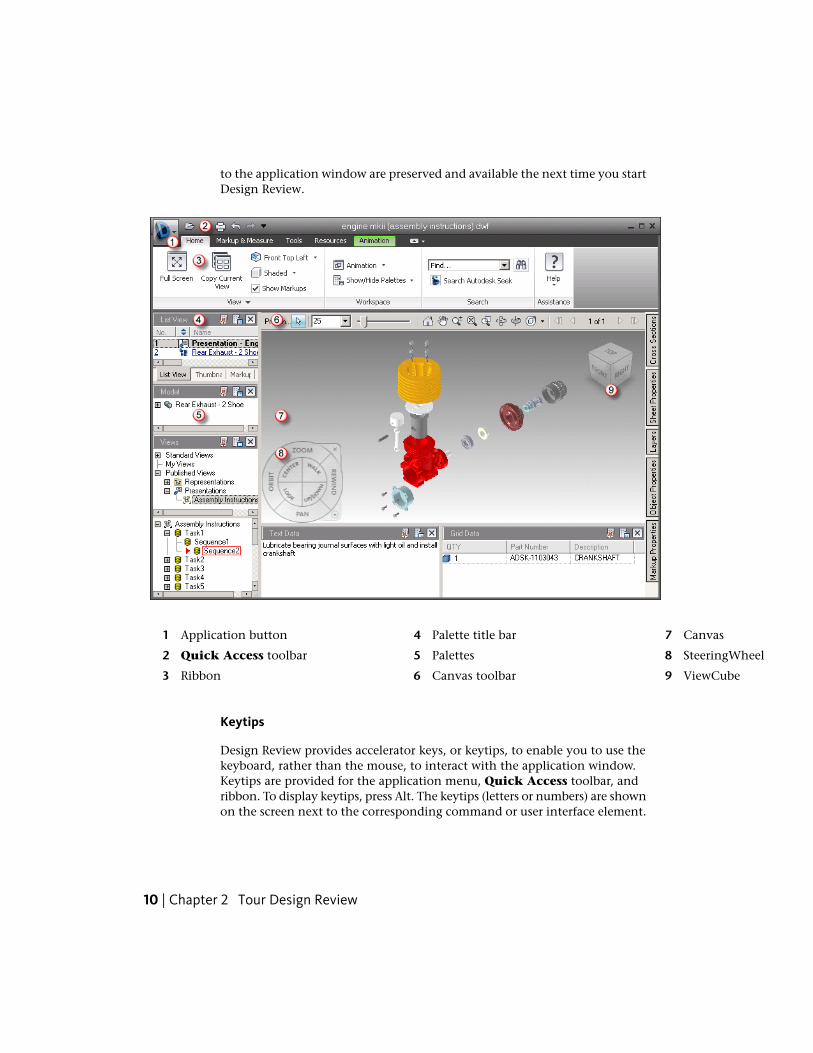
to the application window are preserved and available the next time you startDesign Review.
7 Canvas4 Palette title bar1 Application button
2 85Quick Access toolbar SteeringWheelPalettes
63 9Canvas toolbarRibbon ViewCube
Keytips
Design Review provides accelerator keys, or keytips, to enable you to use thekeyboard, rather than the mouse, to interact with the application window.Keytips are provided for the application menu, Quick Access toolbar, andribbon. To display keytips, press Alt. The keytips (letters or numbers) are shownon the screen next to the corresponding command or user interface element.
10 | Chapter 2 Tour Design Review
Press the appropriate keytip keys to invoke the desired command or to showthe user interface element. To hide the keytips, press Alt again.
Progressive Tooltips
Placing the mouse pointer over a menu choice or a button shows a tooltipcontaining the name of the tool and a keyboard shortcut (if applicable). Sometooltips on the application menu, Quick Access toolbar, and ribbon areprogressive. In addition to the tool name and keyboard shortcut, a briefdescription of the command is also provided. If the mouse pointer remainsover the menu choice or button, the tooltip may expand to show additionalinformation.
See also:
Alternative Methods for Performing Commands (page 257)
System Requirements (page 7)
Check for Design Review Updates (page 255)
About the Application ButtonAt the top, left corner of the application window, the application buttonprovides access to the application menu.
The application button
The application menu enables you to access common tools. Some applicationmenu choices have additional menus that show related commands. Applicationmenu choices include: New, Open, Save, Save As, Security, Print, SendEmail, and Close.
About the Application Button | 11

The application menu
In many locations in the Design Review window, you can accesscontext-sensitive tools using the context menu. Depending on the contentshown and the location of the mouse pointer when you right-click, theavailable tools vary.
Recent Documents List
View the most recently used files with the Recent Documents list. Filesdisplay in the Recent Documents list with the most recently used file atthe top by default.
Pinned Files
You can keep a file listed regardless of files that you save later using the pushpin button to the right. The file is displayed at the bottom of the list until youturn off the push pin button.
Sort and Group Files
At the top of the Recent Documents list, use the drop-down list to sort orgroup files:■ By Ordered List
12 | Chapter 2 Tour Design Review

■ By Access Date
■ By Size
■ By Type
To the right of the sort options, you can use the other drop-down list to showIcons, Small Images, Medium Images, or Large Images to the left offiles in the list.
Preview Documents
Also in the Recent Documents list, place the mouse pointer over a file topreview the file and show information about the file:■ File Location
■ Date Modified
■ Version Info (specifically, the DWF file format version)
■ Currently Open By
Use the Quick Access ToolbarAt the top of the application window, the Quick Access toolbar displaysfrequently used tools.
The Quick Access toolbar
Add unlimited tools to the Quick Access toolbar. Tools that extend past the
maximum length of the toolbar are displayed in a drop-down button.
Use the Quick Access Toolbar
To add a ribbon button to the Quick Access toolbar
1 Display the tab and panel that contains the button you want to add tothe Quick Access toolbar.
2 Right-click the button on the ribbon and select Add to Quick AccessToolbar.
Use the Quick Access Toolbar | 13

To remove a ribbon button from the Quick Access toolbar
■ Right-click the button on the Quick Access toolbar and select Removefrom Quick Access Toolbar.
To undo an action on the canvas
■ On the Quick Access toolbar, click Undo.
If the action was several steps back, repeat this command as needed.
To redo an action on the canvas
■ On the Quick Access toolbar, click Redo.
WARNING Clicking Undo or Redo on the Quick Access toolbar does not affectchanges to the Design Review window. The buttons only affect changes to contenton the canvas.
Use the RibbonThe ribbon is the horizontal area of the application window that containstask-based tabs and panels with tools for viewing, marking up, and sharingDWF files.
Ribbon Tabs and Panels
The ribbon is composed of a series of tabs. Each tab contains a series of panelsorganized by task.
The Home tab
The Markup & Measure tab
14 | Chapter 2 Tour Design Review

The Tools tab
The Resources tab
Contextual Tabs and Panels
Design Review contains one contextual tab and one contextual panel. Bydefault, the Animation tab is hidden. However, when a sheet containing ananimation is shown on the canvas, this context causes the Animation tab tobe shown. The Animation tab provides access to tools used to control how ananimation is played.
The Animation tab is shown only when viewing an animation
Like the Animation tab, by default, the File panel is hidden by default. Whena Design Review file is embedded, this context causes the File panel to beshown on the Home tab. The File panel provides access to tools typicallyavailable on the application button and Quick Access toolbar, which areunavailable in embedded mode. You can also show the File panel manually.
The File panel is shown on the Home tab only when viewing an embedded DWF file
Use the Ribbon | 15
Slideout Panels
In the middle of a panel to the right of a title, an arrow icon, , indicatesthat the panel can slide out to display additional tools and controls. Click thetitle bar of an open panel to display the slideout panel. By default, a slideoutpanel automatically closes when you click another panel. To keep a panel
expanded, click the push pin icon, , in the bottom-left corner of theslideout panel.
Use the Ribbon
To hide or show a ribbon tab
■ Right-click a ribbon tab, click Tabs, and select the desired tab name.
To hide or show a ribbon panel
1 Click the ribbon tab that contains the panels you want to hide or show.
2 Right-click the ribbon tab, click Panels, and select the desired panel.
To show or hide ribbon panel titles
■ Right-click a ribbon tab and select Show Panel Titles.
To restore the ribbon
1 Right-click a ribbon tab and select Restore Ribbon.
The Restore Ribbon dialog box opens.
2 Click Yes.
To use full-screen mode
1 On the canvas, display the sheet or model you want to view full screen.
2 Click Home tab ➤ View panel ➤ Full Screen.
3 Optional: Manipulate the view using the ViewCube or by right-clickingthe canvas and selecting the desired commands.
4 When finished viewing the content in full-screen mode, right-click andselect Full Screen.
16 | Chapter 2 Tour Design Review

The program window, ribbon, toolbars, and palettes are shown in theirprevious locations.
TIP Pressing N is a quick way to control what is shown on the screen. PressN once to hide palettes. Press N again to hide ribbon and Canvas toolbar,showing the current sheet full screen. Press N again to show all items.
See also:
View Animations in 3D DWF Files (page 109)
About Embedding DWF Files (page 235)
Use the Canvas ToolbarThe Canvas toolbar is located above the upper, right corner of the canvas,providing easy access to some common selection, view, and navigation toolsfor working in an open file. When you place the mouse pointer over a button,a tooltip displays. If a button has a small black arrow to the right, clicking thearrow shows buttons for related commands.
Canvas toolbar
By default, Design Review enables the Pan (page 57) tool for 2D DWF filesand the Orbit (page 69) tool for 3D DWF files. When a DWF file has multiplesheets, the arrow buttons on the Canvas toolbar enable you to navigate quicklythrough them.
Depending on the open DWF file and the sheet displayed on the canvas, theCanvas toolbar may show additional icons: one icon to indicate whether ornot the DWF file has been digitally signed and another icon to indicate ifthe sheet contains disablements (page 44).
To affect any item in Design Review, you must first select it.
To select an item
1 On the Canvas toolbar, click Select.
2 Click the item you want to select.
Use the Canvas Toolbar | 17

To select multiple items
1 On the Canvas toolbar, click Select.
2 Click the items you want to select.■ To select consecutive items in a palette, press and hold Shift, click
the first and then the last item in a range, and release Shift. The twoclicked items and all in between are selected.
■ To select non-consecutive items in a palette or on the canvas, pressand hold Ctrl, click the items you want to add to the selection andrelease Ctrl. Ctrl-click any of the selected items to remove that itemfrom the selection.
■ To select multiple 2D markup objects, on the canvas, click and dragthe Select tool around the items you want to select.
■ To exclude some 3D published objects from a selection, select theitems you do not want to be part of a larger selection. Then right-clickand select Invert Selection. The previously selected items areexcluded from the selection.
When more tools are available on a toolbar than are shown, the More button
is displayed at the end of a toolbar.
To show hidden toolbar buttons
1 At the end of a toolbar, click the More button to open a drop-downlist of hidden buttons.
2 Click the desired button.
The Map toolbar cannot be hidden while a map is on the canvas, nor can itbe displayed when no map is displayed. The Canvas toolbar cannot be hidden.
About Contextual Toolbars
The Quick Access and Canvas toolbars are available most of the time inDesign Review. However, some toolbars are displayed depending on thecontent shown on the canvas. These toolbars are contextual. The Grid Data,and Map toolbars are contextual toolbars.
Much like the sheet navigation tools on the Canvas toolbar, the Grid Datatoolbar includes tools for navigating between sheets of tabular data, such asa parts list.
18 | Chapter 2 Tour Design Review

Grid Data palette toolbar
The Map toolbar contains tools for viewing georeferenced maps (page 279). Thetools on the Map toolbar are accessible only when a georeferenced map isshown on the canvas.
Map toolbar
Use Palettes
Manipulate Palettes
A palette is a group of related features that enables you to find and displayinformation about content in a DWF file. There are several palettes:■ Thumbnails and List View palettes. These two palettes show the 2D
and 3D sheets, tables, and other sheets contained in the open DWF file.Clicking a sheet in either palette to display the contents on the canvas.
■ Sheet Properties, Markup Properties, and Object Properties. Forthe selected content, these three palettes show sheet, markup, and object(page 280) properties.
■ Markups. Lists all markups in the DWF file organized by sheet. Clickinga markup displays it on the canvas and displays the Markup Propertiesview in the Properties palette.
■ Model. For 3D models, it lists the objects and subobjects in a 3D model.Clicking an object or subobject highlights it on the canvas.
■ Views. Lists views created in Design Review, and views created inAutoCAD®, Inventor®, and Revit®.
■ Cross Sections. For 3D models, it lists cross sections. A cross section is asection made by cutting a model at an angle, usually to show an interiorview. In the Cross Sections palette, right-clicking a cross section enablesyou to perform various functions, such as flip the cross section, hide thesection plane, deactivate the cross section, and so on.
■ Layers. For 2D sheets, it lists all layers (page 279) for each sheet.Right-clicking a layer enables you to turn the layer on and off.
■ Text Data. Displays textual data, such as assembly instructions, includedwith published animations in a 3D DWF file.
Use Palettes | 19

■ Grid Data. Displays any tabular data, such as a parts list or Bill ofMaterials, included in a DWF file.
■ Find. Quickly locate text in an open DWF file by searching tabular data,markups, objects, sheet names, and properties.
WARNING Clicking the Undo and Redo buttons on the Quick Access toolbardo not affect changes to the Design Review window. The buttons only affectchanges to content on the canvas.
About Palette Positions
In Design Review, the palettes can be manipulated to facilitate your designreview sessions. Palettes can be docked (pinned and unpinned), undocked,and grouped.
A docked palette is one that is attached to the program window and isconstantly available in a workspace. Palettes can be docked in the dockingareas above or below and to the left or right of the canvas. In the dockingareas to the left and right of the canvas, palettes can be stacked vertically and,in the docking areas above or below the canvas, palettes can be positionedside by side.
Stacked palettes
Side-by-side palettes
By default, a docked palette is pinned, meaning that the palette remainsdisplayed at its current size and can be moved. When you unpin a palette andmove the mouse pointer away from it, the palette is reduced to a tab displayingthe palette name. Moving the mouse pointer over the tab displays the palettefully, but temporarily, over the canvas. Unpinning a palette can show more
20 | Chapter 2 Tour Design Review
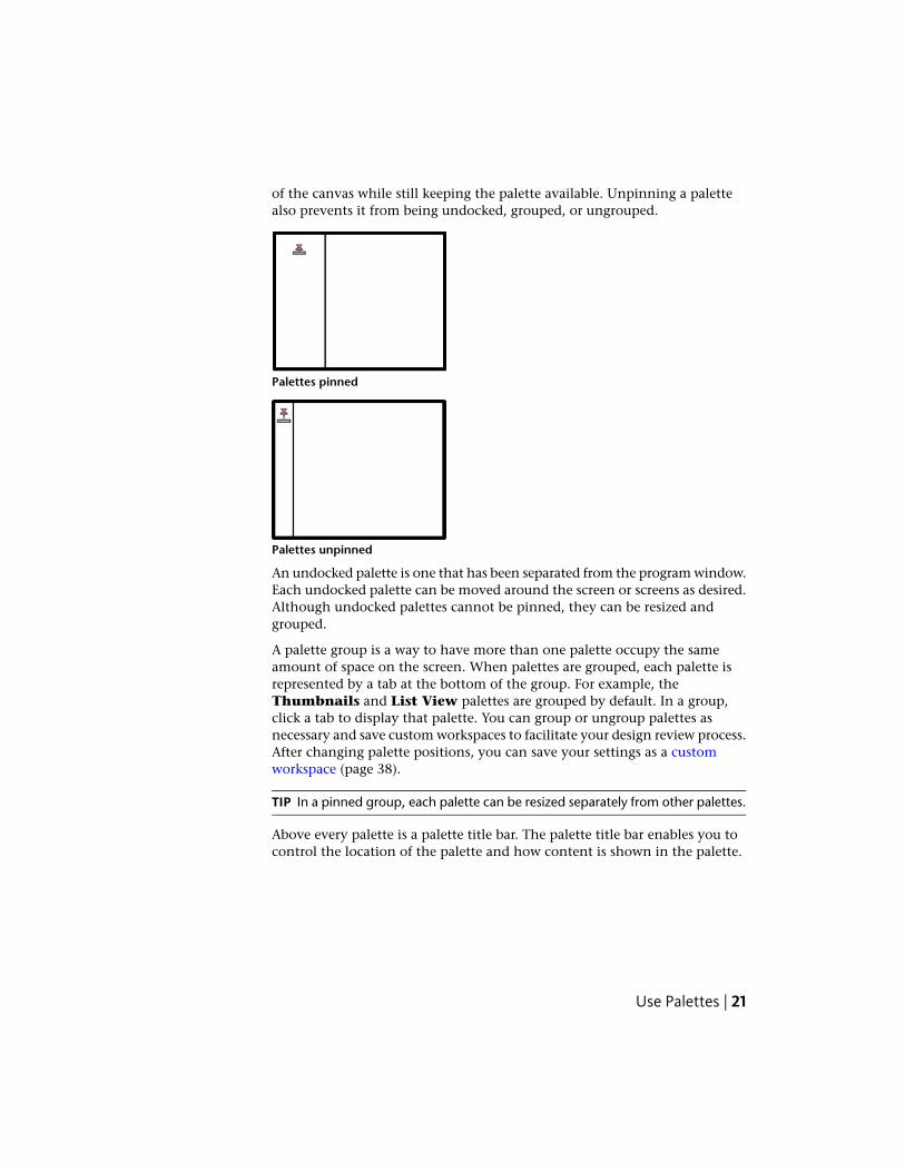
of the canvas while still keeping the palette available. Unpinning a palettealso prevents it from being undocked, grouped, or ungrouped.
Palettes pinned
Palettes unpinned
An undocked palette is one that has been separated from the program window.Each undocked palette can be moved around the screen or screens as desired.Although undocked palettes cannot be pinned, they can be resized andgrouped.
A palette group is a way to have more than one palette occupy the sameamount of space on the screen. When palettes are grouped, each palette isrepresented by a tab at the bottom of the group. For example, theThumbnails and List View palettes are grouped by default. In a group,click a tab to display that palette. You can group or ungroup palettes asnecessary and save custom workspaces to facilitate your design review process.After changing palette positions, you can save your settings as a customworkspace (page 38).
TIP In a pinned group, each palette can be resized separately from other palettes.
Above every palette is a palette title bar. The palette title bar enables you tocontrol the location of the palette and how content is shown in the palette.
Use Palettes | 21

A palette title bar
■ The Pinned and Unpinned buttons control the position of thepalette.
■ The Palette Options button provides access to commands formanipulating palette content.
■ The Close Palette button hides the palette.
Manipulate Palettes
To hide or show a palette
1 Click Home tab ➤ Workspace panel ➤ Show/Hide Palettesdrop-down.
2 Select the desired palette.
To undock a palette
1 Click the title bar of a docked palette and drag the palette over the canvas.
As you begin dragging, an outline of the palette is shown to indicatethat the palette is undocked.
2 Drop the palette to undock it.
To dock a palette
1 Click the title bar of an undocked palette and drag it toward the side ofthe canvas where you would like it docked.
When the palette outline nears that location, the outline snaps to theside of the canvas to indicate that docking is allowed.
2 Optional: Position the palette in relation to any other palettes.
3 Drop the palette to dock it.
To group palettes
1 Click and drag the title bar of the palette to be added to another paletteor group.
2 Drop the palette on the title bar of the receiving palette or group.
22 | Chapter 2 Tour Design Review
A tab, with the name of the dragged palette, is added to the bottom ofthe receiving palette. The palettes are grouped.
Click a tab to display the palette content.
To ungroup palettes
1 Within the palette group, display the palette you want to remove.
2 Click and drag the palette tab out of the group.
3 Drop the palette to ungroup.
To unpin a palette
■ On a palette title bar, click the Pinned button.
The palette becomes unpinned. The Pinned button changes to the
Unpinned button and a tab with the name of the pinned palette isshown on the side of the canvas where the palette is docked. The palettecontinues to be displayed until you move the mouse pointer away fromit. When you move the mouse pointer, the palette is collapsed until youplace the mouse pointer over the palette tab. Repeat this step to pin thepalette.
To resize a palette
1 Place the mouse pointer over a palette border until the mouse pointer
changes to vertical, double-headed arrow or a horizontal, double-headedarrow.
2 Click and drag the border to the desired size.
To scroll within a palette
■ If palette contents are too large to show completely, drag the vertical and/orhorizontal scroll bars inside the palette.
To resize a column within a palette
1 Place the mouse pointer over the line that separates column headingsuntil the mouse pointer changes to a horizontal, double-headed arrow.
2 Drag the mouse pointer left or right to resize the column.
Use Palettes | 23

To sort a palette column in ascending or descending order
■ Click a column heading and the column sorts numerically or alphabetically.Click a column heading again to reverse the sort order.
See also:
General Tab (Options Dialog Box) (page 241)
Thumbnails Palette
The Thumbnails palette shows icons representing 2D and 3D sheets, tables,and other sheets contained in the open DWF file.
Thumbnails Palette
To hide or show the Thumbnails palette
1 Click Home tab ➤ Workspace panel ➤ Show/Hide Palettesdrop-down.
2 Click Thumbnails.
To show a sheet on the canvas
■ In the Thumbnails palette, click the sheet you want to view.
The sheet is shown on the canvas.
NOTE If the sheet in the Thumbnails palette contains tabular data, theinformation is shown in the Grid Data palette.
To change the sheet view in the Thumbnails palette
■ On the Thumbnails palette title bar, click the Palette Options button
and select a sheet view.■ Large Thumbnails. Displays a larger graphical representation of the
sheet and its contents.
■ Small Thumbnails. Displays a smaller graphical representation ofthe sheet and its contents.
24 | Chapter 2 Tour Design Review

See also:
Compose DWF Files (page 133)
Learning Resources: Alternative Methods for Performing Commands (page257)
List View Palette
The List View palette lists 2D and 3D sheets, tables, and other sheetscontained in the open DWF file.
This information is shown in the List View palette.■ The number of the sheet as published. The number indicates the sheet
order in the DWF file.
■ An icon representing the type of sheet. You can sort the list by icon typeby clicking the up or down arrows. The publisher may provide icons. Ifnot, Design Review provides generic icons:■ 2D drawing or image
■ 3D model
■ 3D part
■ iAssembly
■ iPart
■ table
■ presentation
■ The name of the sheet. You can rename a sheet.
■ The size of the sheet.
■ A description, if the publisher of the sheet, model, or table has providedone.
■ The type of content on the sheet. If the publisher has not defined the type,generic types such as Sheet, Model, or Table are displayed.
Use Palettes | 25

List View Palette
To hide or show the List View palette
1 Click Home tab ➤ Workspace panel ➤ Show/Hide Palettesdrop-down.
2 Click List View.
To show a sheet on the canvas
■ In the List View palette, click the sheet you want to view.
The sheet is shown on the canvas.
NOTE If the sheet in the List View palette contains tabular data, theinformation is shown in the Grid Data palette.
See also:
Compose DWF Files (page 133)
Rename a Sheet (page 138)
Learning Resources: Alternative Methods for Performing Commands (page257)
Sheet Properties Palette
The Sheet Properties palette shows properties for the selected sheet. Thesesheet properties are determined by the program that created the DWF file.Sheet properties include may include author, creation time, description,modification time, sheet name, sheet size, and so on.
Sheet Properties Palette
To hide or show the Sheet Properties palette
1 Click Home tab ➤ Workspace panel ➤ Show/Hide Palettesdrop-down.
2 Click Sheet Properties.
26 | Chapter 2 Tour Design Review
To view sheet properties
■ On the canvas or in the Sheet Properties palette, select the sheet thatcontains the properties you want to view.
The properties for the selected sheet display in the Sheet Propertiespalette.
See also:
Search Autodesk Seek (page 54)
Use Palettes (page 19)
Select Items (page 17)
Learning Resources: Alternative Methods for Performing Commands (page257)
Markup Properties Palette
The Markup Properties palette shows properties for the selected markup.These markup properties may include label, reviewing status, locking status,notes, history, markup author, creation time, modification time, and sheetname where the markup resides.
Markup Properties Palette
To hide or show the Markup Properties palette
1 Click Home tab ➤ Workspace panel ➤ Show/Hide Palettesdrop-down.
2 Click Markup Properties.
To view markup properties
■ On the canvas or in the Markups palette, select the markup that containsthe properties you want to view.
The properties for the selected markup display in the Markup Propertiespalette.
See also:
Select Items (page 17)
Use Palettes | 27

About Markup Properties (page 142)
Change Markup Properties (page 154)
Learning Resources: Alternative Methods for Performing Commands (page257)
Object Properties Palette
The Object Properties palette shows properties for the selected publishedobject. These object properties vary widely based on the DWF file publisher’srequirements.
If published objects are nested (objects within objects), only the propertiesfor the top-level object are shown in the palette.
Object Properties Palette
To hide or show the Object Properties palette
1 Click Home tab ➤ Workspace panel ➤ Show/Hide Palettesdrop-down.
2 Click Object Properties.
To view object properties
■ On the canvas or in the Object Properties palette, select the object thatcontains the properties you want to view.
The properties for the selected object display in the Object Propertiespalette.
See also:
Search Autodesk Seek (page 54)
Use Palettes (page 19)
Select Items (page 17)
Learning Resources: Alternative Methods for Performing Commands (page257)
28 | Chapter 2 Tour Design Review
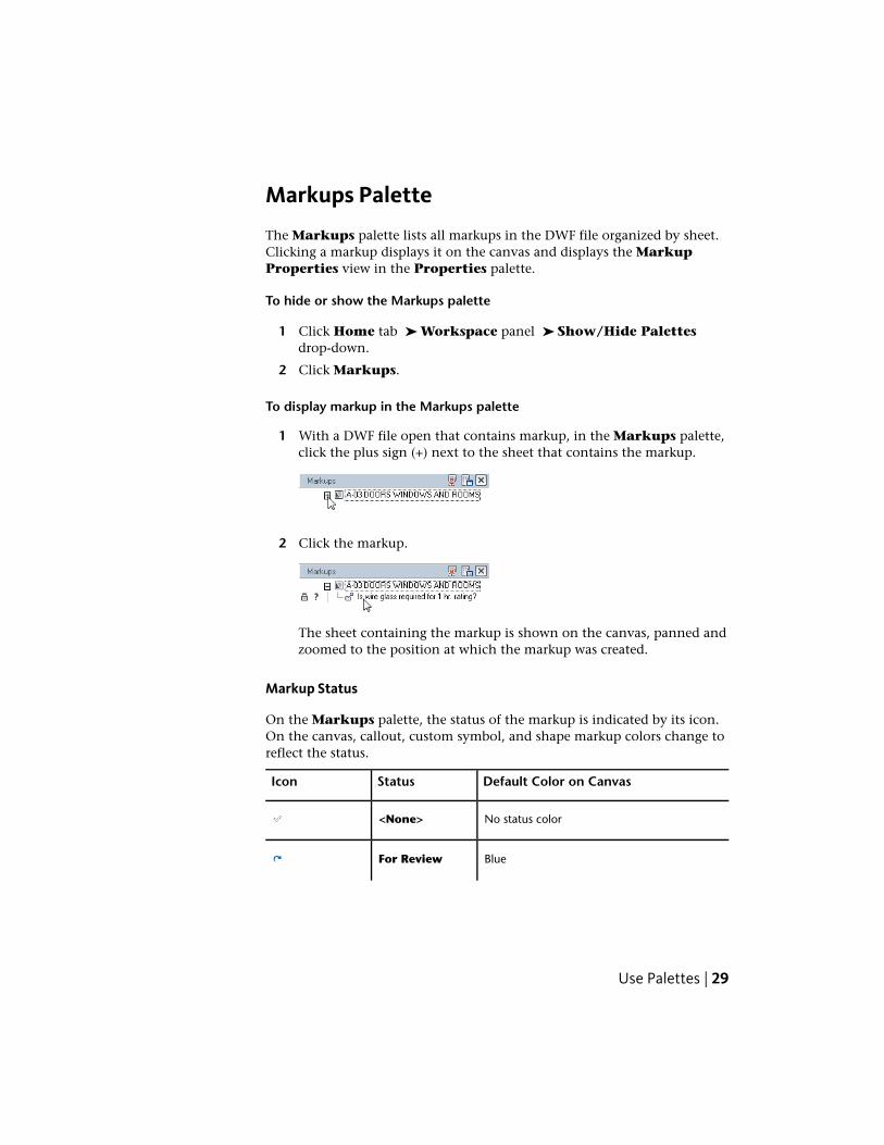
Markups Palette
The Markups palette lists all markups in the DWF file organized by sheet.Clicking a markup displays it on the canvas and displays the MarkupProperties view in the Properties palette.
To hide or show the Markups palette
1 Click Home tab ➤ Workspace panel ➤ Show/Hide Palettesdrop-down.
2 Click Markups.
To display markup in the Markups palette
1 With a DWF file open that contains markup, in the Markups palette,click the plus sign (+) next to the sheet that contains the markup.
2 Click the markup.
The sheet containing the markup is shown on the canvas, panned andzoomed to the position at which the markup was created.
Markup Status
On the Markups palette, the status of the markup is indicated by its icon.On the canvas, callout, custom symbol, and shape markup colors change toreflect the status.
Default Color on CanvasStatusIcon
No status color<None>
BlueFor Review
Use Palettes | 29

Default Color on CanvasStatusIcon
GreenQuestion
YellowDone
NOTE Markup Status can be set or modified from the Properties palette (page27).
The status color highlighting, as defined on the General tab in the Optionsdialog box, can be viewed and printed with the drawing. If you wish to viewor print the drawing and markup without highlighting, you can turn the colorhighlighting off.
See also:
Markup Basics (page 140)
Control Markup Display (page 142)
Change Markup Properties (page 154)
Markup Settings (page 242)
Learning Resources: Alternative Methods for Performing Commands (page257)
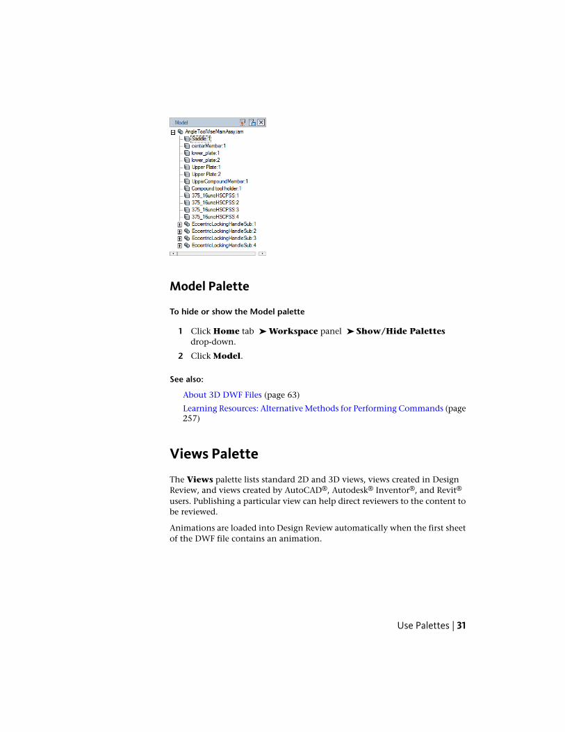
Model Palette
The Model palette contains a tree list of the objects (page 280) and subobjectsof a 3D model. The objects and subobjects within the model are defined bythe publisher of the DWF file.
30 | Chapter 2 Tour Design Review
Model Palette
To hide or show the Model palette
1 Click Home tab ➤ Workspace panel ➤ Show/Hide Palettesdrop-down.
2 Click Model.
See also:
About 3D DWF Files (page 63)
Learning Resources: Alternative Methods for Performing Commands (page257)
Views Palette
The Views palette lists standard 2D and 3D views, views created in DesignReview, and views created by AutoCAD®, Autodesk® Inventor®, and Revit®
users. Publishing a particular view can help direct reviewers to the content tobe reviewed.
Animations are loaded into Design Review automatically when the first sheetof the DWF file contains an animation.
Use Palettes | 31

The Views palette shows several types of views:■ Standard Views. Lists various 3D views such as front, back, top, bottom,
and so on.
■ My Views. Views created in Design Review saved as My View 1, My View2, and so on. My Views can be renamed. Each sheet has its own set of MyViews.
■ Named Views. Views created by Autodesk products that publish namedviews.
■ Published Views. Views and animations published from Inventor.
■ Bookmarks. Views published from Revit.
IMPORTANT Saving to My Views retains display changes, such as cross sections,field of view, layers, lighting, and 3D object movements and rotations.
Views Palette
To hide or show the Views palette
1 Click Home tab ➤ Workspace panel ➤ Show/Hide Palettesdrop-down.
2 Click Views.
To save a view to My Views
1 Arrange the items on the canvas and set the view the way you want itto be saved.
2 Click Home tab ➤ expand the View panel.
3 Click Save View.
The selected view is saved in the Views palette under My Views as MyView 1. Additional views are saved as My View 2, My View 3, and soon. You can rename saved views as desired.
TIP You can also click Save View on the Palette Options drop-down list onthe Views palette title bar.
32 | Chapter 2 Tour Design Review

To rename a saved view
1 In the Views palette, under My Views, right-click the saved view youwant to rename and select Rename.
The Rename View dialog box opens.
2 In the Type New Name text box, type the new name.
3 Click OK.
The new name is applied to the saved view.
To update an existing saved view
1 If necessary, rearrange the items on the canvas and reposition the viewthe way you want it to be saved.
2 In the Views palette, under My Views, right-click the saved view youwant to update and select Save. The new arrangement has been savedto the existing My View.
To delete a saved view
■ In the Views palette, under My Views, right-click saved view you wantto delete and select Delete.
The saved view is deleted.
TIP You can also right-click a saved view and select Reset to Published Viewto return the sheet to the way it was originally published.
To delete all saved views
■ In the Views palette, right-click My Views and select Delete My Views.
All saved views are deleted.
See also:
Start an Animation (page 112)
Use Standard 3D Model Views (page 64)
Learning Resources: Alternative Methods for Performing Commands (page257)
Use Palettes | 33

Cross Sections Palette
The Cross Sections palette lists the cross sections created by you or thepublisher of the 3D model.
IMPORTANT Saving to My Views retains display changes, such as cross sections,field of view, layers, lighting, and 3D object movements and rotations.
Cross Sections Palette
To hide all cross sections on the model
■ In the Cross Sections palette, right-click My Cross Sections and selectActive.
The check mark is removed from the Active command. The section planeand all cross sections are hidden. To display them again, right-click MyCross Sections in the Cross Sections palette and select Active.
To manipulate a cross section from the Cross Sections palette
■ Right-click the cross section you want to manipulate and select the desiredcommand.■ Flip. Flips the cross section.
■ Hide. Hides the section plane.
■ Active. Activates or deactivates the cross section.
■ Viewpoint. Displays the cross section parallel to the screen.
■ Rename. Changes the name of the cross section.
■ Reset. Returns a section plane to its original position.
■ Delete. Deletes a cross section.
To hide or show the Cross Sections palette
1 Click Home tab ➤ Workspace panel ➤ Show/Hide Palettesdrop-down.
2 Click Cross Sections.
34 | Chapter 2 Tour Design Review

To hide the section plane and a cross section temporarily
■ In the Cross Sections palette, right-click the cross section you want tohide and select Active.
■ Click the light bulb next to the Cross Section you want to hide.
See also:
View Cross Sections of a 3D Model (page 100)
Control Caps Display (page 107)
Save Layer Changes as a My View (page 32)
Learning Resources: Alternative Methods for Performing Commands (page257)
Layers Palette
The Layers palette lists all layers on the currently displayed sheet. For example,a layer shows only plumbing and another layer showing electrical. Layerscan be turned on and off, so that they can be viewed individually or alltogether. It is up to the DWF file publisher whether downstream consumerscan turn layers on and off when viewing the DWF file in Design Review.
IMPORTANT Saving to My Views retains display changes, such as cross sections,field of view, layers, lighting, and 3D object movements and rotations.
Layers Palette
To hide or show the Layers palette
1 Click Home tab ➤ Workspace panel ➤ Show/Hide Palettesdrop-downdrop-down.
2 Click Layers.
To hide layers
1 In the Layers palette, select the layer or layers you want to affect.
2 Right-click the selection and select Layer(s) Off.
The selection is hidden.
Use Palettes | 35
TIP You can also click the light bulb to the left of the layer name to hidethe selected layer or layers.
To show layers
1 In the Layers palette, select the layer or layers you want to affect.
2 Right-click the selection and select Layer(s) On.
The selection is shown.
TIP You can also click the darkened light bulb icon to the left of the layername to show the selected layer or layers.
See also:
Save Layer Changes as a My View (page 32)
Learning Resources: Alternative Methods for Performing Commands (page257)
Text Data Palette
The Text Data palette lists all textual data, such as assembly instructions.
Text Data Palette
To hide or show the Text Data palette
1 Click Home tab ➤ Workspace panel ➤ Show/Hide Palettesdrop-down.
2 Click Text Data.
See also:
About Tabular Data (page 119)
36 | Chapter 2 Tour Design Review

Grid Data Palette
The Grid Data palette shows all detail associated with a selection, such aspart details.
Grid Data Palette
To hide or show the Grid Data palette
1 Click Home tab ➤ Workspace panel ➤ Show/Hide Palettesdrop-down.
2 Click Grid Data.
See also:
About Tabular Data (page 119)
Find Palette
The Find palette enables you to locate text quickly in an open DWF file bysearching for tabular data, markups, text on 2D sheets, objects, sheet names,and their properties. Found results are shown in a convenient list, enablingyou to click a result to display the found text or associated object on the canvasor in a palette.
Find Palette
To hide or show the Find palette
1 Click Home tab ➤ Workspace panel ➤ Show/Hide Palettesdrop-down.
2 Click Find.
See also:
Find Text in an Open DWF File (page 53)
Use Palettes | 37

Use WorkspacesWorkspaces retain information about Design Review user interface settings.■ Open palettes
■ Palette positions
■ Application window size
■ Ribbon and Quick Access toolbar changes
■ Markup formatting settings
Workspaces also retain information about certain custom View settings.■ Show Markups
■ Drop Shadows
■ Color
■ Always Show Markups in Color
■ Coordinate Systems
■ Show ViewCube
■ Show Hyperlinks
■ Show Canvas Background
■ Snap to Geometry
NOTE Workspaces do not retain certain settings unique to 3D DWF files such asviewpoint, perspective, lighting settings and so on.
Design Review has two predefined workspaces with palettes arranged to helpfacilitate various review workflows: Default and Animation.
Default■ List View, Thumbnails, Markups, and Model palettes in a tabbed
group.
■ Markup Properties
■ Other palettes are displayed as tabs to the right of the canvas.
Animation■ List View, Thumbnails, and Markups palettes in a tabbed group.
■ Model
■ Views
38 | Chapter 2 Tour Design Review

■ Text Data
■ Grid Data
■ Other palettes are displayed as tabs to the right of the canvas.
NOTE When you select a predefined workspace, the application window resizesto size stored in the workspace. Predefined workspaces use a maximized window.To retain a different application window size, resize the window to the desireddimensions and create a custom workspace.
In addition to the predefined workspaces, you can also create your own customworkspaces to arrange Design Review the way you want it. Once you havecreated your custom workspaces, you can share them with team members andclients as an XML workspace file.
Use Workspaces
To select a predefined workspace
1 Click Home tab ➤ Workspace panel ➤ Workspace drop-down.
2 Select the desired workspace.
To create a custom workspace
1 Arrange the palettes so they are positioned how you want them to besaved.
2 Click Home tab ➤ Workspace panel ➤ Workspace drop-down.
3 Select Save Current Workspace.
The Save Workspace As dialog box opens.
4 In the Enter Workspace Name text box, type the name of the customworkspace.
5 Click OK.
The custom workspace is saved and listed above the predefinedworkspaces. Custom workspaces are listed in the order they were created.
TIP To modify a custom workspace, make the desired changes and save itagain with the same workspace name.
Use Workspaces | 39

To rename a custom workspace
1 Click Home tab ➤ Workspace panel ➤ Workspace drop-down.
2 Select Manage Workspaces.
The Manage Workspaces dialog box opens.
3 From the Current Custom Workspaces list, select the workspace youwant to rename.
4 Click Rename.
The workspace name is selected.
5 Type the name of the workspace and press Enter.
The workspace is renamed.
6 Click Close.
To delete a custom workspace
1 Click Home tab ➤ Workspace panel ➤ Workspace drop-down.
2 Select Manage Workspaces.
The Manage Workspaces dialog box opens.
3 From the Current Custom Workspaces list, select each workspaceyou want to delete.
4 Click Delete.
The Delete dialog box opens.
5 Click OK.
The selected workspaces are deleted and removed from the workspaceslist.
6 Click Close.
To export a custom workspace
1 Click Home tab ➤ Workspace panel ➤ Workspace drop-down.
2 Select Manage Workspaces.
The Manage Workspaces dialog box opens.
3 From the Current Custom Workspaces list, select the workspace youwant to share.
4 Click Export.
The Export Workspace dialog box opens.
40 | Chapter 2 Tour Design Review

5 Optional: Navigate to the location where you want to store the workspacefile.
6 Optional: In the File Name text box, type the name of the workspacefile.
7 Click Save.
A copy of the custom workspace is exported and ready to be shared.
8 Optional: Export another custom workspace.
9 Click Close.
To import a custom workspace
1 Click Home tab ➤ Workspace panel ➤ Workspace drop-down.
2 Select Manage Workspaces.
The Manage Workspaces dialog box opens.
3 Click Import.
The Import Workspace dialog box opens.
4 If necessary, navigate to the location where the workspace file is stored.
5 Select the workspace you want to import.
6 Click Open.
A copy of the custom workspace is imported and added to the CurrentCustom Workspaces list and ready to be used.
7 Optional: Import another custom workspace.
8 Click Close.
See also:
Share Design Review Options (page 252)
Manage Symbol Catalogs (page 172)
Use Workspaces | 41

42
Using Design Review
Receive DWF Files
About Receiving DWF Files
You can receive DWF files several ways.■ As an email attachment
■ From a shared folder on a company network
■ From an Autodesk® Buzzsaw® project folder
■ From an FTP server
■ From a disk, memory card, or other device
■ Embedded in a web page or other file type
NOTE Some DWF files you receive can contain sheets or models that have beenmarkup-, measure-, or print-disabled.
Compatibility with Earlier Versions of Design Review
In Design Review2013, you can open any version of DWF. You can also modifyall markups created in earlier versions of Design Review. When you alter markupcreated by an older version of Design Review and save the DWF file, a warningdialog box opens. To save the DWF file changes in the newer DWF version, clickOK. To retain the original DWF file version but discard any changes, clickCancel.
Earlier versions of Design Review (DWF Composer 1.0, 2.0, and Design Review2007-2012) can view, but not modify, some markups from later versions of
3
43

Design Review. For example, in DWF Composer 1.0, you can view customsymbols, but not select or move them. If earlier versions of Design Review areunable to access certain features, download the latest version. In general, ifyou are having difficulty viewing DWF files, verify that you have the mostcurrent software by clicking Home tab ➤ Assistance panel ➤ Helpdrop-down ➤ Check for Updates.
See also:
About Disabled DWF Files (page 44)
Warn When Upgrading Earlier Versions of DWF (page 242)
Check for Design Review Updates (page 255)
Open Files
About Disabled DWF Files
Design Review enforces disabled DWF files published by Autodesk® Inventor.From Autodesk® Inventor® R11 DWF Extension (available to subscriptioncustomers) or later, you can prevent recipients from measuring some or allsheets or models in their published DWF files. In addition to disablingmeasurement, if you are using Autodesk® Inventor® 2008 or later, you canalso disable markup and printing capabilities for some or all sheets or modelswhen publishing DWF files.
When you open a DWF file that contains disabled sheets, a dialog box openslisting all the disabled sheets and the restrictions for each. (You can preventthis dialog box from opening by checking the Don’t Show Me This MessageAgain check box, or uncheck the Warn When Viewing a Documentwith Restrictions check box on the General tab in the Options dialogbox.)
IMPORTANT Design Review neither creates disabled DWF files, nor does it allowyou to disable existing DWF files. Disabled DWF files are created by Inventor beforethe DWF file is published. Design Review simply enforces the DWF file disablementspublished by Inventor.
When a markup-, measure-, or print-disabled sheet is shown on the canvas,some related tools are disabled. Depending on the disablements, an icon isshown on the Canvas toolbar and in the Restrictions column of the List
44 | Chapter 3 Using Design Review
View palette, indicating that portions of the DWF file contain disabledfeatures.
Placing the mouse pointer over the icon shows all restrictions applied to thecontent on that sheet. Also, DWF files that contains markup-, measure-, orprint-disabled sheets retain their disablements in embedded mode.Furthermore, when disabled sheets are copied or moved to another DWF file,or are saved as a new DWF file, the disablements are retained.
If you have a problem opening a disabled sheet, verify that you have the latestversion of Design Review and contact the publisher of the DWF file.
See also:
About Composing DWF Files (page 133)
About Markup-Disabled DWF Files (page 141)
About Measure-Disabled DWF Files (page 178)
About Print-Disabled DWF Files (page 214)
Warn When Viewing a Document with Restrictions (page 242)
About Opening Other File Types
Besides opening DWF and DWFx files, Design Review can open a wide varietyof other file types for viewing or for saving as a DWF file.■ DWG and DXF files
■ Adobe PDF files
■ Images Files
When opening other file types in Design Review, the original files remainunaffected.
NOTE With the proper Add-ins (page 132) installed, Design Review can also openDGN and JT files.
About Opening DWG and DXF Files
Design Review enables you to open a DWG (page 278) or DXF (page 278) filethrough a background conversion process. To do so, Design Review requires
Open Files | 45
either Autodesk® AutoCAD® or the free DWG TrueView™ program to beinstalled.■ If AutoCAD is installed, the DWG or DXF file can be converted to either
the DWF or DWFx file format. Additional DWG Viewing options areavailable within the Design ReviewOptions dialog box to control theconversion quality.
■ If only DWG TrueView is installed, the DWG or DXF file is converted tothe DWF file format using current DWG TrueView settings.
■ If both are installed, AutoCAD is used to convert the DWG or DXF file.
■ If neither is installed, you are prompted to download and install DWGTrueView.
For the best conversion results, always use a program’s built-in publishingcapabilities.
WARNING If a DWG file contains sheets with uninitialized layouts, those sheetsare not opened in the resulting DWF file.
Opening a DWG or DXF file is the same as opening a DWF file. Both DWGand DXF are part of the All DWF Files (*.dwf, *.dwfx, *.dwg, *.dxf) fromthe Files of Type drop-down list in the Open File dialog box. Once theDWG or DXF file is open on the canvas, you can view and print it just likeany DWF file. If you modify the open DWG or DXF file, you are prompted tosave it as a DWF file to retain the modifications. The original DWG or DXFfile remains unchanged.
TIP When opening a DWG file containing viewports, if the viewports do not displayas expected in Design Review, in the Options dialog box, on the DWG Viewingtab, uncheck the Fit Drawing to This Size option and try reopening the DWGfile.
About Opening PDF Files
Design Review2013 enables you to open PDF files and save them as new DWFfiles. Each PDF page is converted into a new sheet in the opened DWF file.Opening a PDF file is like opening a DWF file, except that you must first selectAdobe PDF (*.pdf) from the Files of Type drop-down list in the OpenFile dialog box. Once the PDF file is open on the canvas, you can view andprint it just like any DWF file. No additional software is required.
Some content in PDF files is not supported by Design Review.■ 3D objects (shown as image)
46 | Chapter 3 Using Design Review

■ Annotations
■ File attachments
■ Forms (shown as image)
■ Hyperlinks (shown as image)
■ Layers and bookmarks
■ Movies and sounds
■ PDF digital signatures (shown as image)
■ PDF files with Security settings
■ PDF markups
■ PDF packages
If a PDF file is password-protected, a dialog box opens prompting for thepassword. Once you enter the password and click OK, protections, such asedit disablements, are not respected by Design Review, nor will they beavailable if the PDF is saved as a DWF file. If a PDF file contains digital rightsmanagement features, Design Review will not be able to open it.
NOTE Design Review cannot save an open DWF file in the PDF file format.
About Opening Image Files
Design Review enables you to open images and save them as new DWF files.The resulting opened content is a raster image. The way to open an image islike opening a DWF file, except that you must first select the desired imagefile format from the Files of Type drop-down list in the Open File dialogbox. No additional software is required.
Design Review can open the several image file types.
Files of TypeSupported Image File Types
*.bmpBitmap files
*.cal, *.cals, *.cg4, *.gp4, *.mil, *.rstMil-R-Raster, multi-sheet files
*.gifGIF files
*.ig4IG4 files
Open Files | 47

Files of TypeSupported Image File Types
*.jpg, *.jpeg, *.jpe, *.jfifJPEG files
*.pcxPaintbrush files
*.pct, *.pictMac files
*.pngPNG files
*.rlcRun Length Compressed files
*.tgaTGA Truevision TARGA files
*.tif, *.tiffTagged Image File Format files
About Limitations of Opened PDF and Image Files
When PDF and image files are opened in Design Review, some features arenot available.■ Snap to Geometry cannot be used.
■ Image text is not searched when using Find.
■ Measurements may be inaccurate.
■ PDF and image files cannot be used with Compare.
About Resolution
The resolution of a file refers to how many dots per inch, or dpi (page 278), areshown on the screen. The more dots per inch (that is, the higher the dpi), thebetter the resolution is, as there is more detail. However, the higher the dpi,the larger the file size.
For DWG files, if AutoCAD is installed, additional DWG Viewing optionsare available within the Design ReviewOptions dialog box to control theconversion quality. Before opening a DWG file use the DWG Viewing optionsto make the resolution higher (specify a larger dpi value) when greater detailis required and make the resolution lower resolution (specify a smaller dpivalue) when faster performance is more important. Drawings are typically
48 | Chapter 3 Using Design Review

created at 400 dpi, the resolution considered most secure, while still allowingacceptable precision of measurements.
For image files, if there is resolution information associated with a file, itdisplays at that resolution. If there is no resolution information associatedwith the image, Design Review displays it at 150 dpi.
For PDF files, additional PDF Conversion options are available within theDesign ReviewOptions dialog box to control the resolution. Before saving aPDF file, use the PDF Conversion options to make the resolution higher(specify a larger dpi value) when greater accuracy of detail is required andmake the resolution lower resolution (specify a smaller dpi value) when fasterperformance is more important.
Related Products
Autodesk® Navisworks® can help you open a wider variety of file types.
See also:
DWG Viewing Tab (Options Dialog Box) (page 249)
About Saving an Open PDF as a DWF File (page 207)
PDF Conversion Tab (Options Dialog Box) (page 250)
Learning Resources: DWG TrueView (page 273)
About the 2D Units and Scale Dialog Box (page 181)
Rotate 2D Sheets (page 62)
About Opening Multiple Files
Unlike many other Windows-based programs, Design Review cannot openmultiple files in one program window. However, you can start multipleinstances of Design Review at the same time.
This capability is useful for some of the following tasks:■ View two or more copies of the same file to review different pages at the
same time.
■ View two or more different files.
■ Create different markups in copies of the same DWF file.
NOTE Save each copy under a different name. If they are saved under thesame name, the last one to be saved overwrites the first.
Open Files | 49
■ Cut and paste markup between different DWF files to save time onrepetitive markup.
■ Drag and drop sheets between different DWF files to compose custom DWFfiles.
TIP From Windows Explorer or the desktop, you can also open multiple DWF filesin separate instances of Design Review by selecting them and then right-clickingthe selection and choosing Open.
Related Products
Autodesk® Navisworks® can help you combine multiple files.
See also:
Compose DWF Files (page 133)
Open a File
As a file opens, a progress bar indicates the status of opening the file. Theprogress bar is especially useful when opening a large file.
Open a File
To open a file
1 Click the application button ➤ Open ➤ Open File.
The Open File dialog box opens and All Supported Files are shownby default.
TIP You can also click the Open button on the Quick Access toolbar.
2 Optional: Navigate to where the file you want to open is stored.
3 Optional: From the Files of Type drop-down list, select the desired fileformat.
This selection persists for the current session. When you exit DesignReview, your preferred file format setting is discarded and All SupportedFiles will be shown again by default the next time you start the program.
50 | Chapter 3 Using Design Review

NOTE When opening other file types in Design Review, the original filesremain unaffected.
4 Select the desired file and click Open.
If the file is password-protected, a dialog box opens prompting for thepassword. Enter the password and click OK.
The file is opened on the canvas.
If you opened a digitally signed DWFx file, information about the signatureis available, and a digital signature icon is shown in the Canvas toolbar.
TIP You can also open recently used files quickly from the Recent Documentson the application menu.
To open a file by dragging and dropping it into Design Review
■ From Windows Explorer or the desktop, drag a supported file to DesignReview and drop it on the canvas.
The file opens in Design Review.
WARNING Dragging a supported file and dropping it into the Thumbnailspalette or the List View palette instead of onto the canvas merges the droppedfile with the currently open DWF file.
To close a file from within Design Review
■ Click the application button ➤ Close.
If no changes were made to the open file, the open file closes. If changeswere made to the open file, you are prompted to save the changes. To savethe changes to the existing file, click Yes. To continue exiting and discardthe changes, click No. To return to the open file, click Cancel.
The open file closes, leaving the Design Review window open.
To exit Design Review
■ Click the application button ➤ Exit Design Review.
If no changes were made to the open file, the open file closes and DesignReview exits. If changes were made to the open file, you are prompted tosave the changes. To save the changes to the existing file, click Yes. Tocontinue exiting and discard the changes, click No. To return to DesignReview, click Cancel.
Open Files | 51

See also:
Combine DWF Files (page 134)
Open a DWF File from Buzzsaw
Autodesk® Buzzsaw® is a collaboration and project management program thatenables team members to deposit, view, copy, discuss, and print documentsor drawings related to a project.
If you are a member of a Buzzsaw project site, you can open and save DWFfiles to that site. Have your user name, password, and location of the fileavailable. See your project or site administrator if you have a problem withBuzzsaw.
Open a DWF File from Buzzsaw
To open a DWF file from Buzzsaw
1 Click the application button ➤ Open ➤ Open from Buzzsaw.
2 Enter your User Name, Password, and Site.
3 Click OK.
4 Optional: Navigate to where the file you want to open is stored.
5 Optional: From the Files of Type drop-down list, select the desired fileformat.
6 Select the desired file and click Open. If the file is password-protected,enter the password.
The file opens and is set to read-only mode. You cannot save changesto it. To save changes, use a different file name.
See also:
Save DWF Files (page 206)
Learning Resources: Other DWF-Related Autodesk Products (page 273)
52 | Chapter 3 Using Design Review

Locate DWF-Related Content
Find Text in an Open DWF File
You can quickly locate text in an open DWF file by searching for tabular data,markups, text on 2D sheets, objects, sheet names, and their properties. Foundresults are shown in a convenient list, enabling you to click a result to displaythe found text or associated object on the canvas or in a palette.
By default, the entire DWF file is searched for the term you enter in the Finddrop-down list. You can narrow your search by clicking the Advanced Searchbutton in the Find palette.■ Find Whole Words Only. Find only whole words that match the text
in the Find drop-down list. For example, if you select Find Whole WordsOnly and search for bolt, Find does not locate the text string bolts or bolted.When the search term contains spaces or punctuation, the Find WholeWords Only option is disabled.
■ Use Wildcards. Find all text that contains a known portion of a word.The question mark (?) wildcard enables you to find words containing anunknown single character. For example w?re finds wire and ware. Theasterisk (*) wildcard enables you to find words containing an unknownstring of characters. For example, l*t finds lift and last. When UseWildcards is selected, the Match Case and Find Whole Words Onlyoptions are disabled.
■ Match Case. Find only text that matches the capitalization used in theFind drop-down list.
■ Find In. Find text in particular locations. Select the type of content beingsearched: All, Current Model or Sheet, Current Table, Markups,Models, Sheets, Tables.
Hidden Text
In some cases, when a DWF file is published, a font is published as geometry.Consequently, although content appears to be text in the DWF file, it is not.As a result, geometric representations of text are not found.
Another instance when text may not be found is when PDF and image filesare opened in Design Review. All text and geometry in the source file israsterized in the resultant DWF file. Consequently, text in such files cannotbe searched.
Locate DWF-Related Content | 53
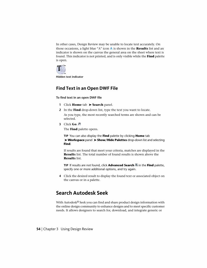
In other cases, Design Review may be unable to locate text accurately. Onthose occasions, a light blue “A” icon is shown in the Results list and anindicator is shown on the canvas the general area on the sheet where text isfound. This indicator is not printed, and is only visible while the Find paletteis open.
Hidden text indicator
Find Text in an Open DWF File
To find text in an open DWF file
1 Click Home tab ➤ Search panel.
2 In the Find drop-down list, type the text you want to locate.
As you type, the most recently searched terms are shown and can beselected.
3 Click Go.
The Find palette opens.
TIP You can also display the Find palette by clicking Home tab ➤ Workspace panel ➤ Show/Hide Palettes drop-down list and selectingFind.
If results are found that meet your criteria, matches are displayed in theResults list. The total number of found results is shown above theResults list.
TIP If results are not found, click Advanced Search in the Find palette,specify one or more additional options, and try again.
4 Click the desired result to display the found text or associated object onthe canvas or in a palette.
Search Autodesk Seek
With Autodesk® Seek you can find and share product design information withthe online design community to enhance designs and to meet specific customerneeds. It allows designers to search for, download, and integrate generic or
54 | Chapter 3 Using Design Review
manufacturer-specific building products or components and associated designinformation.
IMPORTANT Accessing and searching Autodesk Seek requires an active Internetconnection.
NOTE Autodesk Seek is currently available in US English only.
Search Autodesk Seek
To display the Autodesk Seek home page
■ Click Home tab ➤ Search panel ➤ Search Autodesk Seek.
A new browser window opens displaying the Autodesk Seek home page.
On the Autodesk Seek home page, enter one or more terms into the searchbox and click the Search button.
Filtering Search Results
After you have searched for product information, you can reduce the numberof displayed results by applying filters. On the Autodesk Seek web page, applyfilters to narrow the results of a search.
Available filters depend on information supplied by content providers whenthe design files are added to the Autodesk Seek website.
Use Published Hyperlinks
Some DWF files published by AutoCAD, Inventor, and Revit have hyperlinks(page 279) embedded in them, connecting them to other views, drawings, 3Dmodels, web pages, or other data such as parts lists or bills of material.
Some hyperlinks link to multiple locations. When you place the mouse pointerover a hyperlink, a hyperlink viewport is displayed. If more than onedestination exists, the viewport displays “Multiple URLs - Ctrl-click to followlink”. When you press Ctrl and click, the viewport displays a list of the linksyou can follow from the current hyperlink.
Locate DWF-Related Content | 55

Use Published Hyperlinks
To show or hide hyperlinks
1 Click Home tab ➤ expand the View panel.
2 Click Show Hyperlinks.
If there are hyperlinks on the sheet, objects (page 280) and text that do not havehyperlinks turn grayscale (black and white), and objects or text with hyperlinksare typically highlighted in blue.
To hide hyperlinks, repeat this step. The grayscale returns to color, and thehighlighting on hyperlinks are turned off.
To follow a hyperlink
■ Press and hold Ctrl and click the hyperlink (Ctrl-click).
The zoomed view, drawing, model, or web page to which it was linked opens.If the link is to a table or list, the pane that it opens in becomes active.
NOTE If you follow a hyperlink to a table, you may need to resize the Grid Datapalette to view the table.
You can choose to follow included links or not, but you cannot change thehyperlinks in the published DWF file.
See also:
Hyperlink Settings (page 243)
Hyperlinks in Tables (page 122)
56 | Chapter 3 Using Design Review

View DWF Files
Change 2D Sheet Views
View a DWF File in Grayscale or Black and White
When you open a DWF file, it is displayed on the canvas with the colorproperties that were set when it was published. However, you can view thesheets in either shades of gray or black and white.
NOTE The 3D DWF files are shown in grayscale, even if Black & White is selected.
View a DWF File in Grayscale or Black and White
To view a DWF file in shades of gray
1 Click Home tab ➤ expand the View panel.
2 From the Color Depth drop-down list, select Grayscale.
The sheets are shown on the canvas in grayscale.
To view a DWF file in black and white
1 Click Home tab ➤ expand the View panel.
2 From the Color Depth drop-down list, select Black & White.
The sheets are shown on the canvas in black and white.
Pan and Zoom the View of the Canvas
You can change how a sheet or model is displayed on the canvas using thePan and Zoom tools. Panning repositions the vantage point, parallel to asheet or model on the canvas. Zooming in moves the vantage point closer tothe content, making it appear larger. Zooming out moves the vantage pointfarther away from the content, making it appear smaller.
View DWF Files | 57
Neither Pan nor Zoom affects the contents of the sheet or model beingviewed. Only the view of the content changes.
NOTE When a markup is created, the current zoom and pan settings are storedwith that markup.
Pan and Zoom the View of the Canvas
To pan the view of the canvas
1 On the Canvas toolbar, click Pan.
The mouse pointer changes to the Pan tool.
2 Click and drag the mouse pointer to move the view parallel to the screen.
TIP You can also use the arrow keys to pan the view of the canvas.
To zoom the view of the canvas
1 On the Canvas toolbar, click Zoom.
The mouse pointer changes to the Zoom tool.
2 Click and drag the mouse pointer upward to zoom in or downward tozoom out.
TIP With the Zoom tool active, you can also click the canvas to zoom inand Alt-click the canvas to zoom out.
The dragging direction can be switched by changing the Zoom tool settingson the General tab in the Options dialog box.
TIP You can also roll the mouse wheel forward to zoom in and backward to zoomout.
To fit the content to the window
■ On the Canvas toolbar, click Fit to Window.
For 2D content, the canvas view changes to show the greatest possiblemagnification that still shows all content. For 3D content, the canvas viewcenters on the model.
58 | Chapter 3 Using Design Review

To zoom in on a particular area
1 On the Canvas toolbar, click Zoom Rectangle.
The mouse pointer changes to a magnifying glass with a rectangle.
2 Click the canvas to define one corner of the rectangle.
3 Drag the mouse pointer diagonally to define the rest of the rectangulararea.
When viewing 3D objects, as you drag the mouse pointer, a circle displaysin the middle of the rectangular area. The circle defines the new rotationtarget, or pivot.
The view changes to display only the contents in the rectangular areayou defined.
To show the previous view
1 Click Home tab ➤ expand the View panel.
2 Click Previous View.
The previous view is shown.
To show the next view
1 Click Home tab ➤ expand the View panel.
2 Click Next View.
The next view in the sequence is shown.
To hide or show the canvas background in a 2D DWF file
1 Click Home tab ➤ expand the View panel.
2 Click Show Canvas Background.
If the canvas background was shown, it is hidden. If the canvasbackground was hidden, it is shown.
TIP To change the background of a 3D DWF file, in the Options dialogbox, on the Model tab under Color Settings, uncheck Use GradientBackground.
See also:
Change the Rotation Target Point (page 70)
View DWF Files | 59

Changing Design Review Options
Use the 2D Navigation Wheel (page 60)
Change 3D Model Views (page 63)
Quick Reference Guide
Use the 2D Navigation Wheel
Autodesk® SteeringWheels®, or wheels, are part of the Design Review userinterface and provide several ways to change the view. Like a toolbar, eachSteeringWheel provides easy access to many related tools.
The 2D Navigation Wheel is atracking menu (page 281), meaning, whenenabled, it tracks, or follows, the mouse pointer within the canvas. The 2DNavigation Wheel saves you time and clicks by combining Pan and Zoomin a single tool.
NOTE The 2D Navigation Wheel is the only SteeringWheel available whenviewing 2D content.
2D Navigation Wheel
Right-clicking the 2D Navigation Wheel provides access to additionalcommands.
2D Navigation Wheel Menu Commands
DescriptionMenu ChoiceIcon
Reset the view to the original, published view.Go Home
Zoom the view to fit the object on the canvas.Fit to Window
Open the Design ReviewHelp file.Help
Open the Options dialog box SteeringWheels tab.Options
60 | Chapter 3 Using Design Review

Use the 2D Navigation Wheel
To display the 2D Navigation Wheel
1 On the Canvas toolbar, click the SteeringWheel button drop-down.
2 Select 2D Navigation Wheel.
The 2D Navigation Wheel is shown and follows the mouse pointeron the canvas.
To pan the view of the canvas using the 2D Navigation Wheel
1 Click and hold the Pan wedge.
The mouse pointer changes to the Pan tool.
2 Drag the mouse pointer to move the view parallel to the screen.
3 Release the mouse button to exit the Pan tool.
To zoom the view of the canvas using the 2D Navigation Wheel
1 Click and hold the Zoom wedge.
The mouse pointer changes to the Zoom tool.
2 Drag the Zoom tool upward to zoom in, or downward to zoom out.
3 Release the mouse button to exit the Zoom tool.
See also:
Pan and Zoom the View of the Canvas (page 57)
SteeringWheels Tab (Options Dialog Box) (page 246)
Reset the View
Sometimes you want to return the view to the way the person who publishedthe DWF file intended. To do that, reset the view. When you reset a view inDesign Review you have two choices: the home view and the starting view.The home view is a particular view of a file defined by the designer beforepublishing the DWF file. Designers often set a home view to show a part or
View DWF Files | 61
design a certain way to reviewers. The starting view is the view that happenedto be displayed at the time the designer published the file.
If the file has no specified home view, the starting view is shown. If thedesigner had the home view displayed at the time the DWF file was published,the starting and home view are the same in Design Review.
Reset the View
The view returns to the particular view defined by the designer.
To reset the view to the starting view
1 Click Home tab ➤ expand the View panel.
2 Click Starting View.
The view returns to the view that was displayed at the time the designerpublished the file.
TIP For 3D content, you can also right-click the ViewCube and selectStarting View.
Rotate 2D Sheets
Design Review enables you to rotate 2D content, including sheets and rasterimages (page 280). In the Thumbnails or List View palette, you can select asheet and spin it in 90-degree increments, right or left.
The Rotate Sheet Right and Rotate Sheet Left tools have somenoteworthy limitations.■ 2D sheets with markups cannot be rotated. After markups have been added
to the content, Rotate menus and buttons are disabled.
■ 3D sheets cannot be rotated.
■ Tabular data cannot be rotated.
■ Multiple sheets cannot be rotated.
■ A DWF file containing rotated sheets does not display as expected whenit is brought back into a publishing program, such as AutoCAD.
62 | Chapter 3 Using Design Review
TIP When a selected sheet is rotated, the canvas content and the icon in theThumbnails palette are rotated at the same time.
Rotate 2D Sheets
To rotate 2D content
1 In the Thumbnails or List View palette, select the 2D sheet you wantto rotate.
2 Rotate the selection in the desired direction.■ Click Tools tab ➤ Canvas panel ➤ Rotate Sheet Right or
Rotate Sheet Left.
The selected sheet rotates 90°.
See also:
About Opening Image Files (page 47)
Rotate Markup Objects (page 175)
Change 3D Model Views
About 3D DWF Files
A 3D DWF file is one that contains at least one 3D model. A 3D model is ameaningful set of geometrical shapes. Geometrical shapes can be combinedinto meaningful sets, known as “assemblies,” “blocks,” or “objects.” A companymay collect these objects for frequent reuse (electrical parts, mechanical parts,plumbing, or furniture), as they can be plugged into larger drawings or models.A series of doors, for example, can be plugged into various architecturalrenderings.
Each object may include smaller objects, sometimes called subobjects. Eachsubobject, in turn, may be referred to as an object that may contain othersubobjects. For instance, a truck object may have several door subobjects thateach contains several door handle subobjects. It is relative. The relationshipbetween an object and its subobjects is displayed in the hierarchical tree viewin the Model palette.
View DWF Files | 63

NOTE AutoCAD and Inventor do not share a common WCS (page 282) (WorldCoordinate System) with Design Review. In AutoCAD and Inventor, Z is up. InDesign Review, Y is up.
In certain cases, your graphics card may cause problems. For example, a modelmay be displayed incorrectly on the screen. If you experience display problems,on the Model tab of the Options dialog box, you can adjust the View Settings.
Use Perspective View
By default, all 3D views appear as orthographic views, in which all lines oneach axis are parallel to each other. You can add perspective to the views,which shows parallel lines converging to give the illusion of depth. Onlyorthographic views are appropriate for measuring.
To turn on Perspective
1 Click Home tab ➤ expand the View panel.
2 Click Perspective.
The view changes to a perspective view.
Repeat these steps to turn off the perspective view for the 3D content.
TIP You can also right-click the ViewCube to switch between Perspective andOrthographic views.
See also:
View Settings (page 244)
ViewCube Menu (page 73)
Use Standard 3D Model Views
DWF files that include 3D models provide reviewers the ability to virtuallymanipulate objects (or structures), create cross sections, add markup, or tourthe interior of architectural models. With Design Review, you can change theview of a model to a standard view by selecting a view from the StandardViews drop-down on the Home tab ➤ View panel.
Standard 3D Model Views
Front Top Left
64 | Chapter 3 Using Design Review
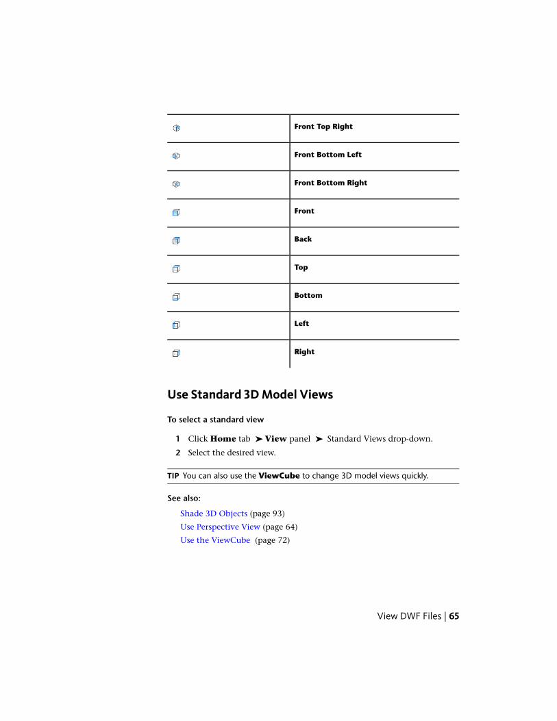
Front Top Right
Front Bottom Left
Front Bottom Right
Front
Back
Top
Bottom
Left
Right
Use Standard 3D Model Views
To select a standard view
1 Click Home tab ➤ View panel ➤ Standard Views drop-down.
2 Select the desired view.
TIP You can also use the ViewCube to change 3D model views quickly.
See also:
Shade 3D Objects (page 93)
Use Perspective View (page 64)
Use the ViewCube (page 72)
View DWF Files | 65
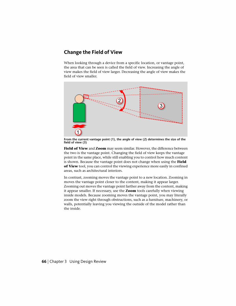
Change the Field of View
When looking through a device from a specific location, or vantage point,the area that can be seen is called the field of view. Increasing the angle ofview makes the field of view larger. Decreasing the angle of view makes thefield of view smaller.
From the current vantage point (1), the angle of view (2) determines the size of thefield of view (3)
Field of View and Zoom may seem similar. However, the difference betweenthe two is the vantage point. Changing the field of view keeps the vantagepoint in the same place, while still enabling you to control how much contentis shown. Because the vantage point does not change when using the Fieldof View tool, you can control the viewing experience more easily in confinedareas, such as architectural interiors.
In contrast, zooming moves the vantage point to a new location. Zooming inmoves the vantage point closer to the content, making it appear larger.Zooming out moves the vantage point farther away from the content, makingit appear smaller. If necessary, use the Zoom tools carefully when viewinginside models. Because zooming moves the vantage point, you may literallyzoom the view right through obstructions, such as a furniture, machinery, orwalls, potentially leaving you viewing the outside of the model rather thanthe inside.
66 | Chapter 3 Using Design Review

The current angle of view is shown in the Field of View tools on the Canvas toolbar
To focus on a single object in the house, such as a fireplace, use the Field ofView tools on the Canvas toolbar to decrease the angle of view, makingthe field of view smaller. The result is that the fireplace appears closer andlarger.
A smaller field of view (left) displays objects closer and larger without moving thevantage point (right)
To see more objects in the room, use the Field of View tools to increase theangle of view, making the field of view larger. The result is that the fireplaceand other objects in the room appear farther away and smaller. You merelyadjust the angle of view to display what you want to see. Your vantage pointstays the same.
View DWF Files | 67

A larger field of view (left) displays more objects farther away and smaller withoutmoving the vantage point (right)
WARNING Extremely large fields of view may distort how objects appear, similarto when Perspective is enabled. Smaller fields of view may cause objects toappear flatter, similar to an orthographic view.
IMPORTANT Saving to My Views retains display changes, such as cross sections,field of view, layers, lighting, and 3D object movements and rotations.
Field of View Limitations
The Field of View tools have some noteworthy limitations.■ The Field of View tools are only enabled when viewing 3D content.
■ The Field of View tools are disabled when an animation is playing orviewing 2D content.
■ Changes to the field of view are only applied to the 3D content currentlydisplayed on the canvas.
■ Changes to the field of view are not specifically saved with the DWF file.However, you can retain Field of View settings as part of a new My Viewor as part of a markup.
68 | Chapter 3 Using Design Review

■ Like other view changing tools in Design Review, you cannot use the Undoor Redo tools to revert or repeat changes made using the Field of Viewtools.
TIP If altering the view produces unexpected results, use Previous View, NextView, or Rewind (on the Full Navigation Wheel) to return the view to anacceptable location.
Change the Field of View
To change the field of view
■ From the Field of View drop-down list, select a preset angle value between10° and 150°.
■ In the Field of View drop-down list, type a precise angle value between1° and 179°.
■ Or, drag the Field of View slider left to decrease or right to increase thearea that can be seen. Like the drop-down list, the slider has preset anglevalues between 10° and 150°.
See also:
Change 3D Views with the Full Navigation Wheel (page 86)
Pan and Zoom the View of the Canvas (page 57)
Views Palette (page 31)
About Markup Properties (page 142)
Use Perspective View (page 64)
Save Field of View Changes as a My View (page 32)
Orbit the View Around a 3D Model
When you use the Orbit tool to change the view of a 3D model, you movethe camera location (the point of view) around a stationary, green sphericalrotation target, called the Pivot. Generally the Pivot is the center of theobject in view. However, if you use the Zoom Rectangle tool or some 3DSteeringWheel tools, the Pivot changes.
View DWF Files | 69

IMPORTANT Saving to My Views retains display changes, such as cross sections,field of view, layers, lighting, and 3D object movements and rotations.
Orbit the View Around a 3D Model
You can rotate the 3D Orbit view several ways:
Rotate. Click and drag in any direction to rotate the view around themodel.
Rotate Horizontally. Press and hold Shift, click, and drag. The rotation ishorizontally constrained.
Rotate Vertically. Press and hold Ctrl, click, and drag. The rotation is ver-tically constrained.
Rotate Parallel to the Screen. Press and hold both Ctrl and Shift, click, anddrag. The rotation is constrained to a plane that is parallel to the screen.
To rotate the view of a model
1 On the Canvas toolbar, click Orbit.
The mouse pointer changes to the Orbit tool.
TIP You can also right-click the canvas and select Orbit.
2 Click and drag to rotate the view of the model.
In the 3D Orbit view, the Pivot is the center of the objects in view.
To change the Pivot location using the Zoom Rectangle tool
1 On the Canvas toolbar, click Zoom Rectangle.
The mouse pointer changes to the Zoom Rectangle tool.
TIP You can also right-click the canvas and select Zoom Rectangle.
2 Click the canvas to define one corner of the rectangle.
70 | Chapter 3 Using Design Review

3 Drag the mouse pointer diagonally to define the rest of the rectangulararea. As you drag, a circle displays in the middle of the rectangular area.The circle defines the new Pivot location.
4 Release the mouse button. The drawing is zoomed to the area that youdefined with the rectangle, and the Pivot is changed to the area definedby the circle.
See also:
Change 3D Views with the View Object Wheel (page 81)
Spin the View of a 3D Model
An alternative to the Orbit tool, the Turntable tool is intended for peopleviewing 3D architectural models, when it is desirable to have the vertical axislocked such that the model cannot be flipped. The Turntable tool enablesyou to examine a model or object while maintaining the view aspect relativeto its base, or the ground, as defined by the DWF publisher.
The Turntable tool prevents the camera angle pass beyond the vertical planewhen rotating horizontally. The maximum camera angle from the horizon is90° (above or below) to help maintain the defined orientation of the model.
TIP Use the Pan and Zoom tools to prepare the view before starting theTurntable tool.
IMPORTANT Saving to My Views retains display changes, such as cross sections,field of view, layers, lighting, and 3D object movements and rotations.
Spin the View of a 3D Model
To spin the view of a 3D model
1 On the Canvas toolbar, click Turntable.
The mouse pointer changes to the Turntable tool.
TIP You can also right-click the canvas and select Turntable.
View DWF Files | 71

2 Change the view of the 3D model horizontally or vertically.■ Click and drag left or right to spin the view of the model around its
vertical axis. This enables you to view the entire outer surface of a3D model while maintaining a constant distance and viewing angle.
■ Click and drag up or down to spin the view of the model around itshorizontal axis. This enables you to view the model from the topdown or from the bottom up.
To constrain the Turntable tool
■ Press and hold Shift and click and drag horizontally or vertically to limitrotation to a restricted linear path along one of these planes.
The Turntable tool remains active until you press Esc or select another tool.
Use the ViewCube
About the ViewCube
The Autodesk®ViewCube® 3D navigation widget is a persistent, clickableinterface that provides a reference to the current orientation of the model andallows you to switch between standard and isometric views quickly.
When the ViewCube is displayed, it is shown in one of the corners of thecanvas, over the model, in an inactive state. While the ViewCube is inactive,it provides a visual reference about the current view of the model as viewchanges occur. When the mouse pointer is positioned near the ViewCube,it becomes active and allows you to switch to one of the available preset views,roll the view, or return to the Home or Starting View of the model.
Some other Autodesk products have also incorporated the ViewCube userinterface. For 3D DWF files published from these applications, the ViewCubeviews in Design Review are the same as the ViewCube views that the designershave in their authoring applications.
The ViewCube
72 | Chapter 3 Using Design Review
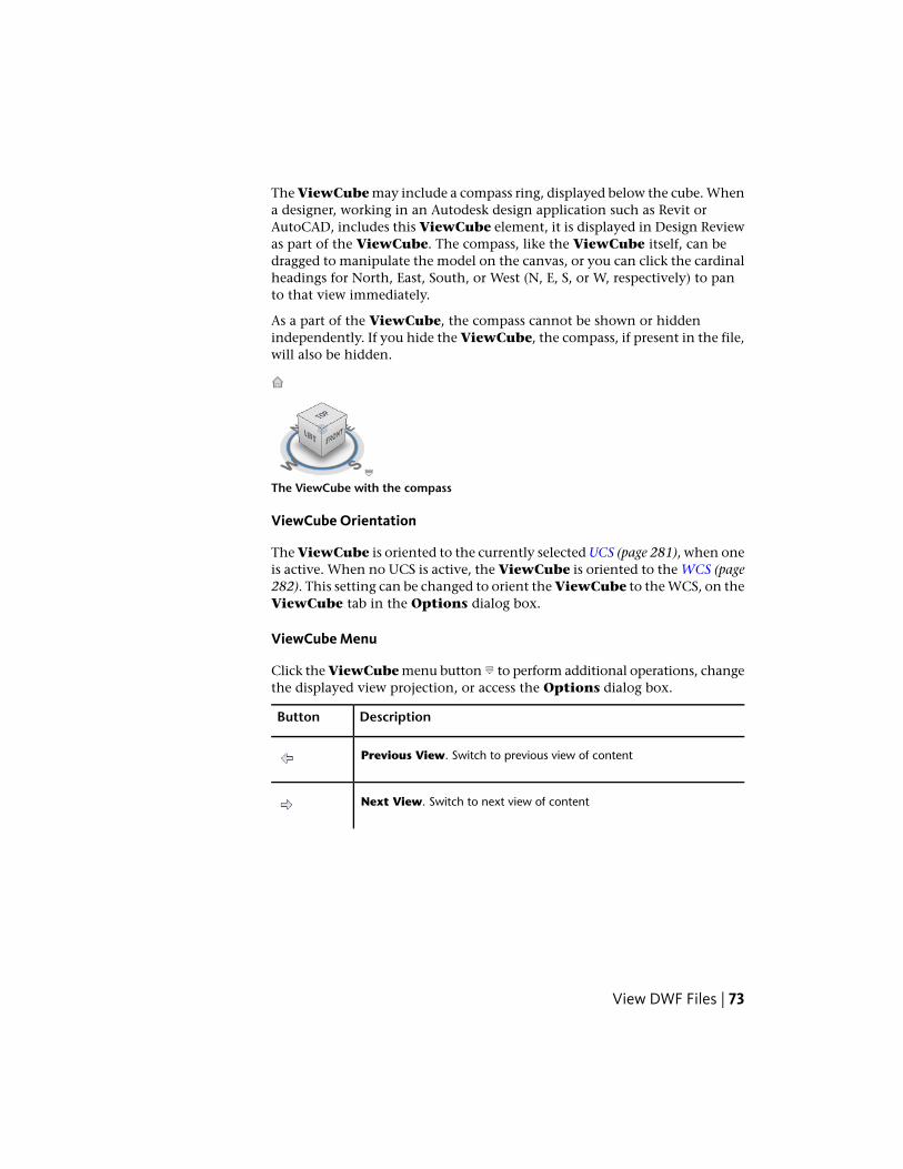
The ViewCube may include a compass ring, displayed below the cube. Whena designer, working in an Autodesk design application such as Revit orAutoCAD, includes this ViewCube element, it is displayed in Design Reviewas part of the ViewCube. The compass, like the ViewCube itself, can bedragged to manipulate the model on the canvas, or you can click the cardinalheadings for North, East, South, or West (N, E, S, or W, respectively) to panto that view immediately.
As a part of the ViewCube, the compass cannot be shown or hiddenindependently. If you hide the ViewCube, the compass, if present in the file,will also be hidden.
The ViewCube with the compass
ViewCube Orientation
The ViewCube is oriented to the currently selected UCS (page 281), when oneis active. When no UCS is active, the ViewCube is oriented to the WCS (page282). This setting can be changed to orient the ViewCube to the WCS, on theViewCube tab in the Options dialog box.
ViewCube Menu
Click the ViewCube menu button to perform additional operations, changethe displayed view projection, or access the Options dialog box.
DescriptionButton
Previous View. Switch to previous view of content
Next View. Switch to next view of content
View DWF Files | 73

DescriptionButton
Starting View. Switch to the initial view of the model. The StartingView is the view that a DWF file publisher had displayed at the time thefile was published.If the designer had their Home view displayed at the time the file waspublished to DWF, the Starting View and Home view will be the samein Design Review.
Home. Switch to the Home view of the model as defined by the designerin the authoring application.If the file has no specified Home view, the Starting View will be used.
Perspective or Orthographic. Switch between Perspective and Or-thographic views.
Options. Opens the Program Options dialog box with the ViewCubetab displayed.
TIP You can also right-click the ViewCube to display the menu.
Control the Appearance of the ViewCube
The ViewCube is displayed in one of two states: inactive and active. Whenthe ViewCube is inactive, it is transparent so that the view of the model isnot obscured. When the ViewCube is active, it appears opaque and mayobscure the area of the canvas and any objects behind it.
Typically the ViewCube is displayed in the inactive state. When the mousepointer is near the ViewCube it becomes active, allowing selection of thevarious ViewCube elements.
In the Options dialog box, on the ViewCube tab, you can set the inactiveopacity of the ViewCube as well as its size, on-screen position, and othersettings.
See also:
Add a User Coordinate System (page 197)
ViewCube Tab (Options Dialog Box) (page 247)
74 | Chapter 3 Using Design Review

Change Views with the ViewCube
Regardless of the tool you are currently using, you can use the ViewCube tochange the view of the model.
IMPORTANT Saving to My Views retains display changes, such as cross sections,field of view, layers, lighting, and 3D object movements and rotations.
Change Views with the ViewCube
To change views with the ViewCube
When you move the mouse pointer over the ViewCube, regions of the cubeare highlighted. The highlighted areas of the ViewCube correspond to thestandard 3D model views, as well as edge views such as Top-Front, or Back-Left.■ Click the ViewCube to pan to the selected view immediately.
To reset the view to the designer assigned home view
■ Above the ViewCube, click the Home button.
The model returns to the Home view.
The ViewCube home view in the DWF file can be assigned by the designerto be the same as the ViewCube home view in the authoring application.If a home view is not specified in the file, clicking the Home button returnsto the starting, or initial, view.
TIP You can also right-click the ViewCube and select either Starting Viewor Home (view).
To view adjacent faces
When viewing a face view, the four small arrows surrounding the ViewCubecan be used to rotate the object to an adjacent face view. For example, whenviewing the Front face, click the arrow to the left of the ViewCube to seethe Left face view.■ Click an Adjacent Face Arrow to pan to that face view.
View DWF Files | 75

ViewCube face view with Adjacent Face Arrows, Roll Arrows, and Home button displayed
To roll a face view
The Roll Arrows near the top, right corner of the ViewCube roll the current
face view 90°, counter-clockwise , or clockwise , each time one is clicked.
NOTE The roll arrows are displayed in different positions, relative to the ViewCube,when the ViewCube location is changed.
■ Click a Roll Arrow to rotate the view 90°.
To orbit an object with the ViewCube
■ Click and drag the ViewCube in any direction.
To hide the ViewCube
1 Click Home tab ➤ expand the View panel.
2 Uncheck Show ViewCube.
The ViewCube is hidden.
TIP You can also enable or disable the ViewCube from the ViewCube tabin the Program Options (page 247) dialog box.
Examine Individual Objects with the ViewCube
When the ViewCube Fit-to-View on View Change (page 248) option is enabled,clicking the ViewCube pans and zooms the view to fit the model, or anycurrently selected part or subobjects, to the canvas. Use the ViewCube, afterpulling a part a model using the Move & Rotate tool, to more closely examinethe part or parts you have moved.
IMPORTANT Saving to My Views retains display changes, such as cross sections,field of view, layers, lighting, and 3D object movements and rotations.
76 | Chapter 3 Using Design Review

Examine Individual Objects with the ViewCube
To use the ViewCube to examine an individual object
1 Select a part in the Model palette, or by clicking one on the canvas usingthe Select tool.
2 Click the desired view on the ViewCube.
The selected object is displayed centered and zoomed on the canvas.
If the view of the selected object is obscured by other parts of the model, youcan hide the obstructions.
To disable Fit-to-View on View Change
1 Click the application button ➤ Options.
2 On the ViewCube tab, uncheck the Fit-to-View on View Changeoption.
3 Click OK.
See also:
Change the Visibility of Objects and Subobjects (page 90)
Pull Apart 3D Models (page 95)
Use the 3D SteeringWheels
Autodesk® SteeringWheels®, or wheels, are part of the Design Review userinterface and provide several ways to change the view. Like a toolbar, eachSteeringWheel provides easy access to many related tools. The tool buttonson the wheel are called wedges (page 282). Design Review has severalSteeringWheels: the 2D Navigation Wheel, View Object Wheel, the TourBuilding Wheel, and the Full Navigation Wheel.
Additionally, the 3D wheels have “Mini Wheel” variants. The Mini Wheelscontain most of the same tool wedges as their full-size counterparts and canbe also be accessed from the Canvas toolbar and wheel context menulocations.
All of the wheels are tracking menus (page 281) because they track, or follow,the mouse pointer within the canvas when a wheel is enabled. The tools varydepending on which SteeringWheel is shown.
View DWF Files | 77
Of the available 3D SteeringWheels, two are sometimes referred to as EasyWheels: the View Object Wheel and the Tour Building Wheel. As theirnames imply, each Easy Wheel is intended to make it easier for reviewers whohave little or no experience manipulating 3D objects on screen to viewparticular types of models. Unlike the Easy Wheels, the Full NavigationWheel contains the complete Easy Wheel toolsets and more. The FullNavigation Wheel is intended for more advanced users of Design Review.
By default, when you view a 3D model, the Full Navigation Wheel isdisplayed, pinned, in the lower-left corner of the canvas. As you move themouse pointer over the pinned wheel, a tabbed dialog box is displayed. Thetabs are labeled “New to 3D” and “Familiar with 3D”. Click either tab to seeinformation about the various SteeringWheels that are available.
On the Familiar with 3D tab, in addition to the Full Navigation Wheel,you have the option of selecting one of the three Mini 3D Wheels. The MiniWheels most of the same tool wedges as their full-size counterparts. The maindifference of with the Mini Wheels, is that the wheel is also the mouse pointer.
IMPORTANT Saving to My Views retains display changes, such as cross sections,field of view, layers, lighting, and 3D object movements and rotations.
Use the 3D SteeringWheels
To unpin a SteeringWheel
1 Move the mouse pointer over the wheel that is pinned to the canvas todisplay the SteeringWheels dialog box.
2 Click either the New to 3D tab or the Familiar with 3D tab.
3 Click a wheel to activate it.
TIP You can also click the pinned wheel itself, or click the SteeringWheel
drop-down on the Canvas toolbar and select a wheel.
To start Design Review with no pinned SteeringWheel displayed
1 Click the application button ➤ Options.
2 On the SteeringWheels tab, in the Display group, uncheck Displaythe Pinned Wheel on Startup.
3 Click OK.
78 | Chapter 3 Using Design Review

The next time Design Review starts, no wheel will be pinned to thecanvas.
NOTE To display the pinned wheel, follow these steps but check the Displaythe Pinned Wheel at Startup option. The next time you start DesignReview, and view a 3D model, the wheel will be pinned to the canvas.
To access the Wheel Menu
■ In the lower, right corner of a wheel, click the Wheel Menu button.
TIP You can also right-click anywhere on a wheel to access the menu.
3D SteeringWheel Menu Commands
DescriptionMenu ChoiceIcon
This button is unavailable. The 2D Navigation Wheel is notavailable when viewing 3D content.
2D Navigation Wheel
Switch to the View Object Wheel.View Object Wheel
Switch to the Tour Building Wheel.Tour Building Wheel
Switch to the Full Navigation Wheel.Full Navigation Wheel
Switch to the Mini View Object Wheel.Mini View Object Wheel
Switch to the Mini Tour Building Wheel.Mini Tour Building Wheel
Switch to the Mini Full Navigation Wheel.Mini Full NavigationWheel
Switch to the Home view of the model as defined by thedesigner in the authoring application.If the file has no specified Home view, the Starting view isused.
Go Home
Zoom the view to fit the object on the canvas.Fit to Window
View DWF Files | 79

DescriptionMenu ChoiceIcon
Rotate the camera angle to zero degrees on the X-axis.Level Camera*
Incrementally increase the speed of the Walk tool.Increase Walk Speed*
Incrementally decrease the speed of the Walk tool.Decrease Walk Speed*
Keep the camera level with the ground while using the Walktool.Checked by default.
Constrain Walk toGround Plane*
This option can also be set on the SteeringWheel tab in theprogram Options dialog box.
Invert the Look tool axis.This option can also be set on the SteeringWheel tab in theprogram Options dialog box.
Invert Axis*
Restore the default Pivot location.Restore Original Center
Open the Design Review Help file.Help
Open the Options Dialog box SteeringWheels tab.Options
Exit the SteeringWheel and switch to the Orbit tool.Close Wheel
* These commands are available on the Full Navigation Wheel and Mini Wheels only.
To close a SteeringWheel
■ In the upper, right corner of a wheel, click the Close button.
NOTE If the wheel is pinned, you must make it active before you can close it.
Related Products
Autodesk® Navisworks® can apply a gravity effect to help you createmore effective architectural walk-throughs.
80 | Chapter 3 Using Design Review

See also:
2D Navigation Wheel (page 60)
Change 3D Views with the View Object Wheel (page 81)
Change 3D Views with the Tour Building Wheel (page 83)
Change 3D Views with the Full Navigation Wheel (page 86)
SteeringWheels Tab (Options Dialog Box) (page 246)
Restore Default Options (page 253)
Change 3D Views with the View Object Wheel
The View Object Wheel, one of the Easy Wheels, contains tools that arecommonly used when viewing assemblies or individual parts. The ViewObject Wheel is only available when 3D content is displayed on the canvas.
View Object Wheel
View Object Wheel Wedges
DescriptionWedge
Redefine the center of rotation for the object.Center
Dynamically zoom the view.Zoom
Return to a previous view.Rewind
Orbit the view of the object.Orbit
IMPORTANT Saving to My Views retains display changes, such as cross sections,field of view, layers, lighting, and 3D object movements and rotations.
View DWF Files | 81

Change 3D Views with the View Object Wheel
To display the View Object Wheel
1 On the Canvas toolbar, click the SteeringWheel drop-down.
2 Select View Object Wheel.
The wheel appears and follows the mouse pointer on the canvas.
To change the Pivot location using the Center wedge
1 On the View Object Wheel, click and hold the Center wedge todisplay the Pivot location.
The mouse pointer changes to the Center tool.
NOTE The Pivot sphere only appears when the mouse pointer is over anobject. When the tool is not over geometry, a circle with a line through it isdisplayed.
2 Drag the Pivot to the location around which you would like to orbit.
3 Release the mouse button to change the Pivot location.
The view pans to show the new Pivot location at the center of thecanvas.
TIP You can also change the Pivot location by clicking the Zoom wedge.
The new Pivot location will be used the next time you orbit the modelusing the Orbit tool, the ViewCube, or the Orbit wedge on one ofthe 3D SteeringWheels.
NOTE You can restore the original Pivot location by right-clicking theSteeringWheel and choosing Restore Original Center.
To zoom the view
1 Click and hold the Zoom wedge.
The mouse pointer changes to the Zoom tool.
2 Drag the Zoom tool upward to zoom in dynamically, or downward tozoom out dynamically.
3 Optional: Click the Zoom wedge once to zoom in incrementally.
82 | Chapter 3 Using Design Review
TIP Press and hold Shift and click the Zoom wedge once to zoom outincrementally.
4 Release the mouse button to exit the Zoom tool.
To return to a previous view
1 Click and hold the Rewind wedge.
A series of thumbnails is displayed. New thumbnails are created eachtime you release the mouse button when using any 3D SteeringWheel.
2 Move the Rewind tool over the thumbnails. As you do so, each of theviews is displayed on the canvas.
3 Release the mouse button to return to the desired view.
TIP Click the Rewind wedge once to rewind a single view only.
To orbit the view of the model
1 Click and hold the Orbit wedge.
The mouse pointer changes to the Orbit tool and the Pivot is displayed.
2 Drag the Orbit tool in any direction to change the view.
NOTE If you redefined the center of rotation using the Center tool, thecamera will orbit around that point. If you did not redefine the center ofrotation, the camera will orbit around the default Pivot location.
3 Release the mouse button to exit the Orbit tool.
See also:
Use the 3D SteeringWheels (page 77)
SteeringWheels Tab (Options Dialog Box) (page 246)
Change 3D Views with the Tour Building Wheel
The Tour Building Wheel, one of the Easy Wheels, contains tools used toconduct a virtual walk-through. The Tour Building Wheel is only availablewhen 3D content is displayed on the canvas
View DWF Files | 83

Tour Building Wheel
Tour Building Wheel Wedges
DescriptionWedge
Move the camera forward within the model.Forward
Turn the camera to look in any direction without moving the camera.Look
Return to a previous view.Rewind
Change the elevation of the camera within the model.Up/Down
IMPORTANT Saving to My Views retains display changes, such as cross sections,field of view, layers, lighting, and 3D object movements and rotations.
Change 3D Views with the Tour Building Wheel
To display the Tour Building Wheel
1 On the Canvas toolbar, click the SteeringWheel drop-down.
2 Select Tour Building Wheel.
The wheel appears and follows the mouse pointer on the canvas.
To move the camera forward
1 Click and hold the Forward wedge.
A target sphere is displayed on the surface under the mouse pointer.
NOTE The target sphere only appears when the mouse pointer is over anobject. When the pointer is not over the model, there is no reference pointfor the camera to move toward.
84 | Chapter 3 Using Design Review

2 Drag the mouse pointer to move the camera toward, or away from, thetarget sphere.
A vertical slider provides an indication of how far from the start positionthe camera has been moved.
TIP You can move the slider beyond both the Surface and Start points.
3 Release the mouse button, when you have moved the camera the desireddistance, to exit the Forward tool.
To look around the view without moving the camera
1 Click and hold the Look wedge.
The mouse pointer changes to the Look tool.
2 Drag the Look tool in any direction to point the camera in that direction.
TIP On the SteeringWheel tab in the Options dialog, you can invert thevertical axis for the Look tool.
3 Release the mouse button to exit the Look tool.
To return to a previous view
1 Click and hold the Rewind wedge.
A series of thumbnails is displayed. New thumbnails are created eachtime you release the mouse button when using any 3D SteeringWheel.
2 Move the Rewind tool over the thumbnails. As you do so, each of theviews is displayed on the canvas.
3 Release the mouse button to return to the desired view.
TIP Click the Rewind wedge once to rewind a single view only.
To change the camera elevation
1 Click and hold the Up/Down wedge.
A vertical slider is displayed.
2 Drag the mouse pointer to increase or decrease camera elevation.
NOTE If you are viewing a model of a multistory building, the Up/Downtool passes through floors and ceilings.
3 Release the mouse button to set the camera elevation.
View DWF Files | 85
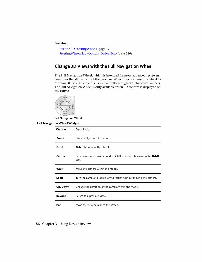
See also:
Use the 3D SteeringWheels (page 77)
SteeringWheels Tab (Options Dialog Box) (page 246)
Change 3D Views with the Full Navigation Wheel
The Full Navigation Wheel, which is intended for more advanced reviewers,combines the all the tools of the two Easy Wheels. You can use this wheel toexamine 3D objects or conduct a virtual walk-through of architectural models.The Full Navigation Wheel is only available when 3D content is displayed onthe canvas.
Full Navigation Wheel
Full Navigation Wheel Wedges
DescriptionWedge
Dynamically zoom the view.Zoom
Orbit the view of the object.Orbit
Set a new center point around which the model rotates using the Orbittool.
Center
Move the camera within the model.Walk
Turn the camera to look in any direction without moving the camera.Look
Change the elevation of the camera within the model.Up/Down
Return to a previous view.Rewind
Move the view parallel to the screen.Pan
86 | Chapter 3 Using Design Review
IMPORTANT Saving to My Views retains display changes, such as cross sections,field of view, layers, lighting, and 3D object movements and rotations.
Change 3D Views with the Full Navigation Wheel
To display the Full Navigation Wheel
1 On the Canvas toolbar, click the SteeringWheel drop-down.
2 Select Full Navigation Wheel.
The wheel appears and follows the mouse pointer on the canvas.
To zoom the view
1 Click and hold the Zoom wedge.
The mouse pointer changes to the Zoom tool.
2 Drag the Zoom tool upward to zoom in dynamically, or downward tozoom out dynamically.
3 Optional: Click the Zoom wedge once to zoom in incrementally.
WARNING The Full Navigation WheelZoom tool also sets a new Pivotlocation.
4 Release the mouse button to exit the Zoom tool.
TIP Press and hold Shift and click the Zoom wedge once to zoom outincrementally.
To zoom the view without changing the Pivot location
■ Press and hold Ctrl and click the Zoom wedge.
The view zooms incrementally in toward the current Pivot location.
To orbit the view of the object
1 Click and hold the Orbit wedge.
The mouse pointer changes to the Orbit tool and displays the Pivotlocation.
View DWF Files | 87

The Pivot location may differ from the default if you set a new targetwith the Center tool, or if you used the Full Navigation WheelZoomtool.
2 Drag the Orbit tool to move the camera view around the Pivot.
NOTE When viewing the interior of an architectural model, you may find iteasier to use Zoom, Pan, Walk, or Look tools to change the view.
3 Release the mouse button to exit the Orbit tool.
To change the Pivot location using the Center wedge
1 On the Full Navigation Wheel, click and hold the Center wedge todisplay the Pivot location.
The mouse pointer changes to the Center tool.
NOTE The Pivot sphere only appears when the mouse pointer is over anobject. When the tool is not over geometry, a circle with a line through it isdisplayed.
2 Drag the Pivot to the location around which you would like to orbit.
3 Release the mouse button to change the Pivot location.
The view pans to show the new Pivot location at the center of thecanvas.
TIP You can also change the Pivot location by clicking the Zoom wedge.
The new Pivot location will be used the next time you orbit the modelusing the Orbit tool, the ViewCube, or the Orbit wedge on one ofthe 3D SteeringWheels.
NOTE You can restore the original Pivot location by right-clicking theSteeringWheel and choosing Restore Original Center.
To move the camera
1 Click and hold the Walk wedge.
The mouse pointer changes to the Walk tool.
2 Drag the mouse pointer in any direction to move the camera. Forexample, drag upward to walk forward, or downward to walk backward.
TIP You can set whether the Walk tool is constrained to the ground planeon the SteeringWheels tab in the Options dialog box.
88 | Chapter 3 Using Design Review
3 Release the mouse button to exit the Walk tool.
Change the movement speed
You can change the speed at which you move through a model whenusing the Walk tool.
NOTE The Walk tool must be active to change the movement speed.
■ To increase or decrease walk speed
■ Right click the SteeringWheel and select Increase Walk Speedor Decrease Walk Speed.
To change the camera elevation while using the Walk tool
1 While using the Walk tool, press Shift to display the Up/Downslider.
2 Drag up or down to change the elevation of the camera.
TIP Make minor camera height changes while walking by pressing the upor down arrows.
To look around the view without moving the camera
1 Click and hold the Look wedge.
The mouse pointer changes to the Look tool.
2 Drag the Look tool in any direction to point the camera in that direction.
TIP When the Look tool is enabled, you can move the camera by pressingthe arrow keys.
3 Release the mouse button to exit the Look tool.
To change the camera elevation
1 Click and hold the Up/Down wedge.
A vertical slider is displayed.
2 Drag the mouse pointer to increase or decrease camera elevation.
NOTE If you are viewing a model of a multistory building, the Up/Downtool passes through floors and ceilings.
3 Release the mouse button to set the camera elevation.
View DWF Files | 89
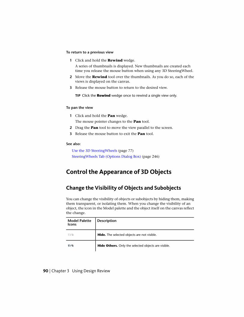
To return to a previous view
1 Click and hold the Rewind wedge.
A series of thumbnails is displayed. New thumbnails are created eachtime you release the mouse button when using any 3D SteeringWheel.
2 Move the Rewind tool over the thumbnails. As you do so, each of theviews is displayed on the canvas.
3 Release the mouse button to return to the desired view.
TIP Click the Rewind wedge once to rewind a single view only.
To pan the view
1 Click and hold the Pan wedge.
The mouse pointer changes to the Pan tool.
2 Drag the Pan tool to move the view parallel to the screen.
3 Release the mouse button to exit the Pan tool.
See also:
Use the 3D SteeringWheels (page 77)
SteeringWheels Tab (Options Dialog Box) (page 246)
Control the Appearance of 3D Objects
Change the Visibility of Objects and Subobjects
You can change the visibility of objects or subobjects by hiding them, makingthem transparent, or isolating them. When you change the visibility of anobject, the icon in the Model palette and the object itself on the canvas reflectthe change.
DescriptionModel PaletteIcons
Hide. The selected objects are not visible.
Hide Others. Only the selected objects are visible.
90 | Chapter 3 Using Design Review

DescriptionModel PaletteIcons
Transparent. The selected objects are faintly visible.
Invert Selection. Click the objects that you do not want selected.All the others are selected.
Change the Visibility of Objects and Subobjects
To change the visibility of an object
■ In the Model palette or on the canvas, right-click an object or subobjectand select Hide, Hide Others, or Transparent.
On the canvas, the object is shown with the desired effect. In the Modelpalette, the object icon also reflects the change.
To show all hidden objects in the model
■ In the Model palette, right-click and select Show All.
■ On the canvas, right-click and select Show All Objects.
On the canvas, all hidden objects are shown as originally published. Inthe Model palette, the object icons reflect the change.
Control Lighting Effects for 3D Objects
Design Review provides some predefined lighting schemes that vary in colorand intensity. These lighting effects are intended to make it easier to discern3D objects when displayed in Design Review. Only one lighting effect can beapplied to a model at a time.
DescriptionLighting Effect
Enables a common set of lighting values. These values are appliedunless Published Lights were provided by the authoring applic-ation.
Default Lights
Enables a single bright light from the front.Headlamp
View DWF Files | 91

DescriptionLighting Effect
Enables lighting effects created in the authoring application. Ifno lights were published by the authoring application, the Pub-lished Lights option is disabled.
Published Lights
Disables all lighting effects. The model is shaded with flat render-ing.
No Lights
Only displayed when the open DWF file contains previouslysupported lighting effects from an earlier version of Design Re-view.
Legacy Lights*
*Legacy Lights cannot be applied to the displayed model.
Lighting effects persist only as long as the DWF file is open in Design Review.If you exit Design Review and reopen the same file, or open the same file ina separate instance, you will have to reapply your preferred lighting effect.You can, however, save a view with applied lighting effects using or by creatinga markup.
NOTE When printing the DWF file or the currently loaded sheet, any lighting effectapplied during the current session will be applied to the printed output.
IMPORTANT Saving to My Views retains display changes, such as cross sections,field of view, layers, lighting, and 3D object movements and rotations.
Control Lighting Effects for 3D Objects
To change the lighting effect
1 Click Home tab ➤ expand the View panel.
The current lighting effect is shown on the Lighting Effects drop-downlist.
2 From the Lighting Effects drop-down list, select the desired lightingeffect.
The selected lighting effect is applied to the model.
92 | Chapter 3 Using Design Review

See also:
Save Lighting Changes as a My View (page 32)
Markup 3D DWF Files (page 176)
Shade 3D Objects (page 93)
View Shadows for 3D Objects (page 94)
Shade 3D Objects
Objects are shaded by default.
IMPORTANT Saving to My Views retains display changes, such as cross sections,field of view, layers, lighting, and 3D object movements and rotations.
Shade 3D Objects
To change the shading of objects
1 Click Home tab ➤ View panel ➤ Shading/Edges drop-down.
2 Select the desired shading option.
DescriptionTool
Shaded. Shades the objects with a smoother, more realistic appear-ance.
Edges Only. Displays objects with lines and curves.
Shaded with Edges. Combines the shading and edges.
See also:
Control Lighting Effects for 3D Objects (page 91)
Save Shading Changes as a My View (page 32)
View DWF Files | 93

View Shadows for 3D Objects
Design Review can show shadows for 3D models. When you view a 3D modelin Design Review, you can enable shadows to enhance your understandingof the object being reviewed.
By default, shadows are disabled. When enabled, shadows are visible for allitems displayed on the canvas. If you choose to hide objects or subobjects, orto make some parts transparent, the shadows displayed on the canvas reflectthis choice.
The angle from which the shadows are cast is fixed and relative to the model.So when the light direction option is set to Top, the shadows are cast fromthe direction that is the “top” of the object as it was published. When viewingan object in Design Review, the object’s published “top” could be the side orthe bottom face of the object.
If you have set the current model to view Edges Only, no shadows aredisplayed. Select Shaded or Shaded with Edges to see shadows.
NOTE If shadows are enabled when printing the DWF file, shadows are includedin the print output.
View Shadows for 3D Objects
To show or hide 3D shadows
1 Click Home tab ➤ expand the View panel.
2 Click Drop Shadows.
Repeat this step to restore the shadows to their previous setting.
See also:
Drop Shadow Settings (page 245)
Shade 3D Objects (page 93)
Control Lighting Effects for 3D Objects (page 91)
94 | Chapter 3 Using Design Review
Pull Apart 3D Models
Move and Rotate 3D Objects
Design Review enables you to move and rotate 3D objects using the Move &
Rotate tool.
By pulling a model apart, you can better view an object or see how an objectfits into the larger model.
WARNING Design Review does not share a common WCS (World CoordinateSystem) with AutoCAD and Inventor. In Design Review Y is up, in AutoCAD andInventor Z is up.
The Move & Rotate tool remains active. To use it again, click another object.If you click outside an object, the tripod is not visible because you have notselected an object. Once you click an object, the tripod is displayed again. TheMove & Rotate tool also remains active after using the Print, Copy CurrentView, Fit to Window, Previous View, and Next View tools. To end theuse of the Move & Rotate tool, click another tool or press Esc.
IMPORTANT Saving to My Views retains display changes, such as cross sections,field of view, layers, lighting, and 3D object movements and rotations.
Move and Rotate 3D Objects
TIP Keep the tripod slightly oblique to the screen to facilitate moving or rotatingthe selection.
To move a 3D object
1 Click Tools tab ➤ 3D Tools panel ➤ Move & Rotate.
The mouse pointer changes to the Move & Rotate tool.
TIP You can also right-click the canvas and select Move & Rotate.
2 In the Model palette or on the canvas, click the object or objects thatyou want to move.
View DWF Files | 95

3 Drag the selection in any direction. If multiple objects are selected, dragthe origin of the first object to move the entire selection.
TIP You can also use the arrow keys to move the view left, right, up, ordown.
End moveBegin move
To move a 3D object along an axis
1 Click Tools tab ➤ 3D Tools panel ➤ Move & Rotate.
The mouse pointer changes to the Move & Rotate tool.
TIP You can also right-click the canvas and select Move & Rotate.
2 In the Model palette or on the canvas, click the object or objects thatyou want to move.
3 On the axis along which you want to move the object, click that axisnear the origin.
4 Drag the axis in either direction to move the selection.
TIP You can also use the arrow keys to move a selected object along an axis.
End moveBegin move
96 | Chapter 3 Using Design Review

To move a 3D object within a plane
1 Click Tools tab ➤ 3D Tools panel ➤ Move & Rotate.
The mouse pointer changes to the Move & Rotate tool.
TIP You can also right-click the canvas and select Move & Rotate.
2 In the Model palette or on the canvas, click the object or objects thatyou want to move.
3 Rollover a plane defined by two axes until an indication of a plane witharrows is shown, and click.
4 Drag the selection in any direction.
TIP To see this feature more clearly, click Home tab ➤ expand the Viewpanel, and click Perspective.
End moveBegin move
To move a 3D object parallel to the screen
1 Click Tools tab ➤ 3D Tools panel ➤ Move & Rotate.
The mouse pointer changes to the Move & Rotate tool.
TIP You can also right-click the canvas and select Move & Rotate.
2 In the Model palette or on the canvas, click the object or objects thatyou want to move.
3 Click the tripod origin and drag the selection in any direction.
View DWF Files | 97
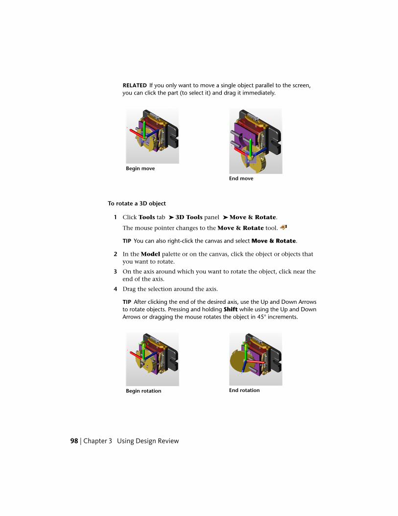
RELATED If you only want to move a single object parallel to the screen,you can click the part (to select it) and drag it immediately.
End move
Begin move
To rotate a 3D object
1 Click Tools tab ➤ 3D Tools panel ➤ Move & Rotate.
The mouse pointer changes to the Move & Rotate tool.
TIP You can also right-click the canvas and select Move & Rotate.
2 In the Model palette or on the canvas, click the object or objects thatyou want to rotate.
3 On the axis around which you want to rotate the object, click near theend of the axis.
4 Drag the selection around the axis.
TIP After clicking the end of the desired axis, use the Up and Down Arrowsto rotate objects. Pressing and holding Shift while using the Up and DownArrows or dragging the mouse rotates the object in 45° increments.
End rotationBegin rotation
98 | Chapter 3 Using Design Review
Once a DWF file is closed, moves and rotations are not saved.
To save a view of a moved or rotated object
■ Save a view using My Views.
■ Add a markup. The view can then be accessed from the Markups palette.
See also:
Reset 3D Objects (page 99)
About Coordinate Systems (page 196)
Use the Arrow Keys to Move and Rotate (page 270)
Save 3D Object Movement and Rotation Changes as a My View (page 32)
Markup DWF Files (page 140)
Reset 3D Objects
After changes have been made to parts of a model, it is common to want tosee a model the way it was originally published. View the original positionsby resetting one object at a time or by resetting the entire model all at once.You have a few choices to reset 3D objects.
Reset 3D Objects
To return one 3D object to its original position
■ In the Model palette, right-click a moved object and select Reset.
■ With the Move & Rotate tool active, double-click a moved object on thecanvas to reset it to its original position.
■ Or, with a moved object selected, on the Model palette toolbar, click the
Palette Options button and select Reset.
To return all 3D objects in a model to their original positions
■ In the Model palette, right-click the top-level assembly and select Reset.
■ Or, with the top-level assembly selected, on the Model palette toolbar,
click the Palette Options button and select Reset.
■ Right-click the ViewCube and select Starting View.
View DWF Files | 99

View Cross Sections of a 3D Model
Cross Section 3D Models
A cross section is a cut-away view of an object. Cross sections enable you tosee inside 3D objects. You can create a cross section by cutting through amodel or object using the section plane. The transparent section plane is theactual on-screen interface you can move to create a cross section. When youbegin a cross section, a cross section tripod and section plane are displayed.The tripod enables you to move the section plane.
The cross sectioning tools can create a Section Face, XY Section, YZSection, and a XZ Section, each representing a plane defined by two of thethree tripod axes.
Design Review, AutoCAD, and Inventor do not share a common WCS (WorldCoordinate System). In Design Review, Y is up. In AutoCAD and Inventor, Zis up.
TIP Keep the tripod slightly oblique to the screen to facilitate moving or rotatingthe selection.
Cross Section 3D Models
To cross section a 3D model on a face
1 Click Tools tab ➤ 3D Tools panel ➤ Section Face.
The mouse pointer changes to the Section Face tool.
2 Click the desired model surface to create the cross section.
The section plane is applied where you click the model. The mouse
pointer changes to the Modify Cross Section tool.
100 | Chapter 3 Using Design Review

3 Optional: Drag the tripod to position the section plane as needed.
The resulting section is added to the Cross Sections palette. The firstsection you create is listed under My Cross Sections as Cross Section1.
To cross section a 3D model on a plane
1 Click Tools tab ➤ 3D Tools panel.
2 Select the desired cross section plane type: XY Section , XZ Section , YZ Section.
The section plane cuts the model in half to reflect the section plane type
and the mouse pointer changes to the Modify Cross Section tool.
3 Drag the tripod to position the section plane as needed.
The resulting cross section is added to the Cross Sections palette. Thefirst section you create is listed under My Cross Sections as CrossSection 1.
You can create numerous cross sections on a model, which are numberedsequentially, such as Cross Section 2, Cross Section 3, and so on. When creatingmultiple cross sections, only the currently selected section plane is visible.The other section planes are not visible, but the effects of them (the crosssections) remain visible.
IMPORTANT Saving to My Views retains display changes, such as cross sections,field of view, layers, lighting, and 3D object movements and rotations.
See also:
Move and Rotate 3D Objects (page 95)
Cross Sections Palette (page 34)
Save Cross Section Changes as a My View (page 32)
View DWF Files | 101

Move and Rotate Section Planes
You can change the cross section revealed, or move or rotate a section plane.To move or rotate the section plane, position the mouse pointer over thetripod, or between the axes. Hot spots appear, each allowing you to move thesection plane in a different way.
Move and Rotate Section Planes
To move a section plane
1 In the Cross Sections palette, select the cross section you want to move.
The section plane and tripod are shown.
2 On the tripod, click the origin.
3 Drag the origin in any direction.
TIP You can also use the arrow keys to move the section plane left, right,up, or down.
End moveBegin move
To move a section plane along an axis
1 In the Cross Sections palette, select the cross section you want to move.
The section plane and tripod are shown.
2 On the tripod, click the desired axis near the origin.
3 Drag the axis in either direction along the axis.
102 | Chapter 3 Using Design Review
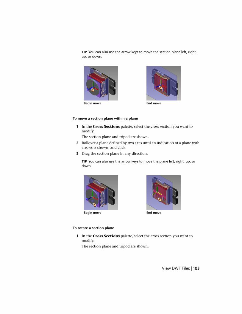
TIP You can also use the arrow keys to move the section plane left, right,up, or down.
End moveBegin move
To move a section plane within a plane
1 In the Cross Sections palette, select the cross section you want tomodify.
The section plane and tripod are shown.
2 Rollover a plane defined by two axes until an indication of a plane witharrows is shown, and click.
3 Drag the section plane in any direction.
TIP You can also use the arrow keys to move the plane left, right, up, ordown.
End moveBegin move
To rotate a section plane
1 In the Cross Sections palette, select the cross section you want tomodify.
The section plane and tripod are shown.
View DWF Files | 103

2 On the axis around which you want to rotate the plane, click near theend of the axis.
3 Drag to rotate the section plane around the selected axis.
TIP You can also use the arrow key to rotate the section plane.
End rotationBegin rotation
RELATED If you press and hold Shift while using the arrow keys to rotate,the section plane rotates in 45° increments.
IMPORTANT Saving to My Views retains display changes, such as cross sections,field of view, layers, lighting, and 3D object movements and rotations.
See also:
Use the Arrow Keys to Move and Rotate (page 270)
Save Move and Rotation Changes as a My View (page 32)
Flip Cross Sections
After you create a cross section, you can flip it for a different view of the object.
IMPORTANT Saving to My Views retains display changes, such as cross sections,field of view, layers, lighting, and 3D object movements and rotations.
104 | Chapter 3 Using Design Review

Flip Cross Sections
To flip a cross section
■ In the Cross Sections palette, right-click the desired cross section andselect Flip.
The section plane flips.
See also:
Save Cross Section Changes as a My View (page 32)
Hide or Show a Section Plane
By default, a section plane (the plane that cuts the object) and its tripod areshown.
IMPORTANT Saving to My Views retains display changes, such as cross sections,field of view, layers, lighting, and 3D object movements and rotations.
Hide or Show a Section Plane
To hide a section plane
■ In the Cross Sections palette, right-click the desired cross section andselect Hide.
The section plane and the tripod are hidden, leaving the cross sectionvisible.
TIP To hide all cross sections, on the ViewCube click the Home button.
To show a section plane
■ In the Cross Sections palette, right-click the hidden cross section andselect Hide again.
The section plane and the tripod are shown.
See also:
Save Cross Section Changes as a My View (page 32)
View DWF Files | 105
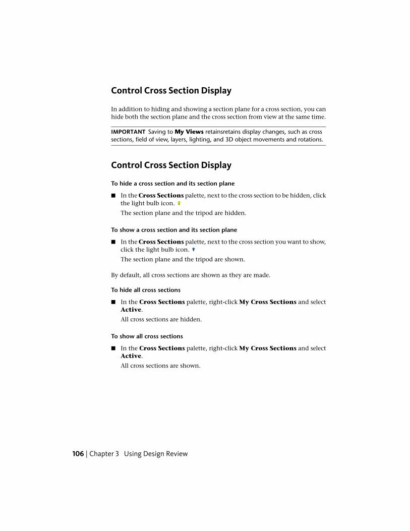
Control Cross Section Display
In addition to hiding and showing a section plane for a cross section, you canhide both the section plane and the cross section from view at the same time.
IMPORTANT Saving to My Views retainsretains display changes, such as crosssections, field of view, layers, lighting, and 3D object movements and rotations.
Control Cross Section Display
To hide a cross section and its section plane
■ In the Cross Sections palette, next to the cross section to be hidden, clickthe light bulb icon.
The section plane and the tripod are hidden.
To show a cross section and its section plane
■ In the Cross Sections palette, next to the cross section you want to show,click the light bulb icon.
The section plane and the tripod are shown.
By default, all cross sections are shown as they are made.
To hide all cross sections
■ In the Cross Sections palette, right-click My Cross Sections and selectActive.
All cross sections are hidden.
To show all cross sections
■ In the Cross Sections palette, right-click My Cross Sections and selectActive.
All cross sections are shown.
106 | Chapter 3 Using Design Review

Control Caps Display
A cross section slices through objects showing a flat surface, or cap, across allobjects. The sectioning tools cap all cross sections by default. Uncapping crosssections shows objects as if they were hollow.
IMPORTANT Saving to My Views retains display changes, such as cross sections,field of view, layers, lighting, and 3D object movements and rotations.
Uncapped cross sectionCapped cross section
Control Caps Display
To uncap cross sections
■ In the Cross Sections palette, right-click My Cross Sections and selectCap.
The cross sections are uncapped and hollow spaces are visible.
Repeat this step to cap the cross sections.
View a Cross Section Parallel to the Screen
To view a cross section parallel to the screen
■ In the Cross Sections palette, right-click the desired cross section andselect Viewpoint.
The object on the canvas is panned and zoomed so that section plane isparallel to the screen.
View DWF Files | 107

Rename a Cross Section
Each cross section you create is added to the Cross Sections palette under MyCross Sections. By default they are named Cross Section 1, Cross Section 2,and so on.
To rename a cross section
1 In the Cross Sections palette, right-click the desired cross section andselect Rename.
The Rename Cross-Section dialog box opens.
2 Enter a new name for the cross section and click OK.
The new cross section name is displayed under My Cross Sections.
Reset a Section Plane
When you manipulate a section plane, after creating it, you can quickly resetit to its original position.
Reset a Section Plane
To reset a section plane
■ In the Cross Sections palette, right-click the desired cross section andselect Reset.
The section plane appears as it was originally placed.
To reset all section planes
■ In the Cross Sections palette, right-click My Cross Sections and selectReset.
Delete Cross Sections
To delete a cross section
■ In the Cross Sections palette, right-click the desired cross section andselect Delete.
108 | Chapter 3 Using Design Review

The selected cross section is deleted.
To delete all cross sections on the model
■ In the Cross Sections palette, right-click My Cross Sections and selectDelete All.
All cross sections are deleted.
TIP If you delete a cross section by mistake, you can retrieve it by clickingUndo on the Quick Access toolbar.
View Animations in 3D DWF Files
About Animations in DWF Files
Design Review allows you to view animations and assembly instructions, ifpublished, created by Autodesk Inventor. Animations allow downstreamreviewers to observe the details of assembly and/or component objects moreclosely and see how and in what order they fit together. To view assemblyinstructions, display the Text Data palette.
Animations are listed in the Views palette under PublishedViews ➤ Presentations. When you click an animation title, Explosion 1 inthe example below, the Views palette is extended to display the animationchapters and sequences; and the animation begins playing. The labels for eachview, chapter, and sequence are defined by the DWF publisher and cannot bechanged.
The Views palette, extended after selecting an animation
View DWF Files | 109

About Animations in DWF Files
To expand an item in the tree list
■ Next to an item in the tree list, click the plus button (+). The tree item isexpanded and its children are shown in the tree list.
To collapse an item in the tree list
■ Next to an item in the tree list, click the minus button (-). The tree itemis collapsed and its children are no longer visible in the tree list.
Related Products
Autodesk® Navisworks® can help you produce AVI files from animations.
See also:
View Tabular Data (page 119)
Use Palettes (page 19)
About Animation Tools
When a sheet (3D model) that is selected in the Thumbnails or List Viewpalette contains an animation, the conditional Animation tab is displayedin the Design Review ribbon. Animations can be published to playautomatically, active mode, or manually, inactive mode.
If a sheet contains an active animation, the animation begins automaticallyand the animation tools are active. If the sheet contains more than oneanimation, or inactive animations, select an animation in the Views palette(Published Views ➤ Presentations) or, from the Select Animationdrop-down list on the Animation tab ➤ Settings panel.
Use the Animation tab ➤ Controls panel to control animation playback.
DescriptionTool
Play. Plays the animation forward.
110 | Chapter 3 Using Design Review
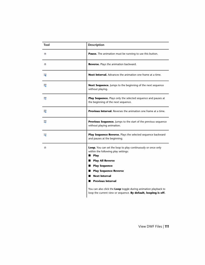
DescriptionTool
Pause. The animation must be running to use this button.
Reverse. Plays the animation backward.
Next Interval. Advances the animation one frame at a time.
Next Sequence. Jumps to the beginning of the next sequencewithout playing.
Play Sequence. Plays only the selected sequence and pauses atthe beginning of the next sequence.
Previous Interval. Reverses the animation one frame at a time.
Previous Sequence. Jumps to the start of the previous sequencewithout playing animation.
Play Sequence Reverse. Plays the selected sequence backwardand pauses at the beginning.
Loop. You can set the loop to play continuously or once onlywithin the following play settings:
■ Play
■ Play All Reverse
■ Play Sequence
■ Play Sequence Reverse
■ Next Interval
■ Previous Interval
You can also click the Loop toggle during animation playback toloop the current view or sequence. By default, looping is off.
View DWF Files | 111

DescriptionTool
Camera. You can turn off/on all published camera changes in aDWF file animation.By default, camera changes are enabled.
Animation Trails. You can show or hide publishedtrails (page281) during playback. If the publisher did not include trails, thebutton is unavailable.By default, trails are not displayed.
Speed. You can set the playback speed of the animation. Select aspeed:
■ Slow
■ Medium (default setting)
■ Fast
See more about changing animation playback speed (page 117).
Select Animation. If more than one animation is present in thecurrent sheet, click the Select Animation arrow and select an an-imation to view.
Start an Animation
Unless the first sheet in the DWF file contains an animation, Design Reviewdoes not automatically display the animation tools. When you select a sheetin either the Thumbnails palette or the List View palette that contains ananimation, the Animation tab displays, the workspace automatically changesto Animation workspace and the first active animation (if more than oneexists in the file) begins playing.
If the animation does not play automatically, the model is shown on thecanvas in the first frame, or interval, of the animation.
112 | Chapter 3 Using Design Review
Start an Animation
To start an animation
■ Click Animation tab ➤ Controls panel ➤ Play.
See also:
Use Workspaces (page 38)
View Animations
When a 3D sheet containing an active animation is opened, the animationbegins playing by default. However, you can stage the entire animation, achapter, or a sequence, by clicking the animation, chapter, or sequence namewhen the extended Views palette is displayed.
View Animations
To view an animation from the beginning
1 If necessary, display the Views palette.
2 In the tree list, from Published Views ➤ Presentations, select ananimation.
3 If necessary, click Animation tab ➤ Controls panel ➤ Play.
The animation begins playing on the canvas.
View DWF Files | 113

When an animation is running, the sequence being viewed is highlighted withinthe extended Views palette.
To view part of a larger animation
1 In the extended Views palette, click the plus button (+) next to thename of an item in the tree list.
The tree item is expanded to display a hierarchical list of chapters andsequences that combine to create the parent animation. Further expandthe chapter tree items as needed.
2 Select the chapter or sequence from which you would like to beginviewing the animation.
3 Click Animation tab ➤ Controls panel ➤ Play.
The animation begins playing on the canvas from the chapter or sequenceyou selected.
To view a single sequence only
1 Select the sequence to view.
2 Click Animation tab ➤ Controls panel ➤ Play Sequence.
The selected sequence begins playing on the canvas.
TIP You can also play a single sequence by double-clicking the sequencename in the extended Views palette.
114 | Chapter 3 Using Design Review

To view an entire animation backward
1 In the extended Views palette, select the last sequence, at the bottomof the Animation tree list.
2 Click Animation tab ➤ Controls panel ➤ Reverse.
The animation begins playing in reverse.
IMPORTANT During animation playback, some Design Review features are disabled.The ribbon buttons that enable these features are unavailable.
For a complete list of animation control buttons and a description of each,see About Animation Tools (page 110).
Markup Animations
Adding markup to an animation is like adding markup to other 3D DWF filesexcept that the animation cannot be running.
Markup Animations
To markup an animated 3D DWF
1 Click Animation tab ➤ Controls panel ➤ Pause.
2 Click Markup and Measure ➤ Callouts panel ➤ Rectangle Callout.
The mouse pointer changes to a crosshair.
3 Place the mouse pointer over the model where you want to begin theleader line.
4 Click and drag the label to the desired location and click again to set thelabel position.
5 Type the comment text in the label. The label expands to accommodatethe text.
6 Click outside the label to complete the callout on the canvas and todisplay the label text under the sheet name in the Markups palette.
7 Click Animation tab ➤ Controls panel ➤ Play to continueanimation playback.
View DWF Files | 115
IMPORTANT When you continue animation playback after adding markup, yourmarkups will no longer be displayed. Access markup applied to animations in theMarkups palette.
See also:
Markup 3D DWF Files (page 176)
Markups Palette (page 29)
Markup Basics (page 140)
Take a Snapshot of an Animation
To take a snapshot of an animation
1 Click Animation tab ➤ Controls panel ➤ Pause.
2 Click Tools tab ➤ Create Sheet panel ➤ From Snapshot.
3 Move and resize the snapshot capture window as necessary.
4 Click the Capture button to finish the snapshot.
A 2D Snapshot sheet is added to the Thumbnails and List Viewpalettes. This sheet is also displayed on the canvas so you can addmarkup.
You can rename your snapshot.
See also:
Create a New 2D Sheet by Taking a Snapshot (page 137)
Rename a Sheet (page 138)
Save a View (page 32)
Change How an Animation Is Displayed
You can use various tools of Design Review to change the view while ananimation is running.
Once you have made an animation sequence active in the Views palette, youcan use the Pan, Zoom, Zoom Rectangle, Orbit, Turntable, or CrossSection tools to interact with the animation.
116 | Chapter 3 Using Design Review
Changes you make using these tools remain in effect until the animation callsfor an object movement or camera change.■ If you move an object while the animation is paused, or before playing
the animation, the object reappears in its original position when thesequence that includes that object begins.
■ If you change your view of the animation, during playback or while paused,your view is lost when the animation advances to the next chapter orsequence. To maintain your view changes, disable camera changes (page117).
Use the Settings panel on the Animation tab to enhance your viewingexperience.
Change the Animation Speed
You can change the speed at which an animation runs. The default speed foranimation playback is Medium. Slow plays the animation at 1/3 the defaultspeed. Fast plays the animation at three times the default speed.
To change the animation speed
1 Click Animation tab ➤ Controls panel ➤ Speed drop-down list.
2 Select Slow, Medium, or Fast.
Enable or Disable Looping
Set Design Review to automatically replay the animation. By default, loopingis disabled.
To enable or disable animation looping
■ Click Animation tab ➤ Controls panel ➤ Loop to enable automaticreplay of the animation.
■ Click Loop again to disable automatic replay.
Disable or Enable Camera Changes
Occasionally, you may want to disable the automatic camera changes calledfor in an animation. By default, camera changes are enabled.
View DWF Files | 117
To disable or enable animation camera changes
■ Click Animation tab ➤ Controls panel ➤ Camera to disableanimation camera changes.
■ Click Camera again to enable the published camera changes.
Show or Hide Trails
You may find it helpful to see the movement trails (page 281) of objects whileviewing an animation. By default, trails are not displayed.
To enable or disable object trails in animations
■ Click Animation tab ➤ Controls panel ➤ Animation Trails toenable trails in the animation.
■ Click Animation Trails again to disable trails in the animation.
Although you can change the look and orientation of an object while usingthe animation viewer, Design Review cannot save changes to animations.When you close the program, the changes you made are lost.
See also:
Save a View (page 32)
About Viewing Assembly Instructions
Assembly instructions are attached to individual sequences in an animationby the DWF publisher. They explain, step by step as the animation advances,how to create the currently loaded assembly. They can include text instructionsand parts lists and are meant for use in a manufacturing setting to provideclear and concise instructions in conjunction with Design Review’s View An-imations (page 113) feature. If the publisher does not include assemblyinstructions, you cannot create them in Design Review.
When an animated DWF file with assembly instructions is opened in DesignReview, the instructions are displayed for the current task or sequence in theText Data palette.
118 | Chapter 3 Using Design Review

IMPORTANT Although loading a DWF file may populate the Text Data or GridData palettes, these palettes may not be displayed automatically. Display palettesmanually by clicking Home tab ➤ Workspace panel ➤ Show/Hide Palettesdrop-down list.
In Design Review, you can set whether palettes display automatically on theOptions dialog box ➤ General tab in the Automatic Palette Launchinggroup.
Depending on the current workspace layout, the text and grid data palettesmay be displayed unpinned at the edge of the canvas. If necessary, place themouse pointer over the Text Date or Grid Data tab to display the palette,and click the lock button to keep the palette displayed.
The Text Data palette displays text such as step-by-step instructions forassembly.
The Grid Data palette displays data in list or table formats such as a partslist or a Bill of Materials.
NOTE In the Grid Data palette, the appearance and behavior of a BOM thataccompanies an animation differs from a stand-alone BOM table. With ananimation, only the parts that move during a task, or sequence, are displayed.
Selecting an animation chapter or sequence displays the published assemblyinstruction for that part of the animation in the Text Data palette and stagesthat part of the animation on the canvas. Parts corresponding to thatinstruction are shown in the Grid Data palette.
See also:
General Tab (Options Dialog Box) (page 241)
Manipulate Palettes (page 19)
View Tabular Data (page 119)
View Tabular Data
About Tabular Data
Design Review can display a table of information about the parts within anassembly that may include quantities, names, costs, vendors, and other details
View DWF Files | 119

someone building the assembly might need. This data may be a Bill of Materials(BOM (page 277)) or a more generic parts list. This type of tabular data is typicallyused by design, purchasing, and manufacturing personnel to controlproduction and track changes.
In Design Review, you can view a 2D drawing or 3D model whilesimultaneously viewing tabular data. Suppliers, contractors, fabricators, andmanufacturers can print tables or, using Design Review, mark them up usingthe From Grid and markup tools.
About Tables
When a DWF file is published with tabular data, the table is formattedaccording to the complexity of the designed object. Published tabular datamay be one of two types:■ H Grid Table. A hierarchical table displays expandable parent/container
items that may contain still more expandable items. You can move itemswhich are at the same level, within the same parent, but you cannot changethe level (promote or demote) of an object. This type of table is commonlyused for BOM information.
■ Grid (Flat) Table. A table in which all items are at the same level(non-hierarchical). You can move items within a flat table by draggingand dropping. Flat tables are more commonly used for parts lists.
When you select an item in a table, whether a single part or an assembly, thatitem is also selected in the Model palette and on the canvas. Additionally,when an object is selected on the canvas or in the Model palette, the part isscrolled to (in larger tables) and highlighted in the table.
NOTE If the selected part is small or an interior component, it may not be apparentthat it is also selected on the canvas. In the Model palette, right-click the part andselect Hide Others to display only the selected part on the canvas.
See also:
Change the Visibility of Objects and Subobjects (page 90)
120 | Chapter 3 Using Design Review
View Tabular Data
If the Grid Data palette is not already displayed, set up the Design Reviewworkspace to view tabular data.
View Tabular Data
To view tabular data
■ In the Thumbnails or List View palette, click a table or a named Bill ofMaterials.
The Grid Data palette opens below the canvas and displays the table.The canvas is resized, but continues to display the current sheet or model.
NOTE You may need to resize the Grid Data palette.
To hide or show the Grid Data palette
1 Click Home tab ➤ Workspace panel ➤ Show/Hide Palettes.
2 Select Grid Data.
The Grid Data palette opens.
To expand an item in a tree list
■ In a tree list, to the left of a tree item, click the plus sign (+).
The tree item is expanded and its children items are shown in the tree list.
When you select an item in the table, either an individual component or anentire subassembly, it is also selected on the canvas and in the Model palette.If the table you are viewing is linked to a 2D sheet, clicking an item in thetable automatically pans and zooms the sheet to display that part on thecanvas.
To collapse an item in a tree list
■ In a tree list, to the left of a tree item, click the minus sign (-).
The tree item is collapsed and its children items are hidden in the tree list.
You can rearrange rows in the table, but you cannot change the level of anitem. For example, you cannot promote a child part to the level of a parent
View DWF Files | 121
assembly or demote a parent to the level of a child; child parts cannot bemoved into another parent assembly.
To move table rows
■ Drag and drop rows up or down.
To move table columns
■ Drag and drop column headers left or right.
To hide or show columns
■ Right-click a column header and select columns to display in the table. Acheck mark indicates that a column is shown. Click a column title to clearthe check mark and hide the column.
To resize a column
1 Place the mouse pointer over the line that separates column headersuntil the mouse pointer changes to a horizontal, double-headed arrow.
2 Drag the mouse pointer left or right to resize the column.
RELATED To change column width to fit the content, double-click theseparator bar to the right of the column heading.
To change the sort order of a column
■ Click once on the header of the column you want to sort.
If you have modified the format of the Grid Data palette while viewing atable, such as changing the position, width, or visibility of columns, or theorder in which the rows are displayed, the view settings for that table persistuntil you exit Design Review. Any other table in the same DWF file uses thedefault view settings.
Format changes to the Grid Data palette are not persistent across reviewingsessions, and are lost when you exit Design Review.
Hyperlinks in Tables
Publishers may include hyperlinks in table cells that either correspond to apublished iPart (page 279) or open a sheet or model from the Thumbnails palette.
122 | Chapter 3 Using Design Review
Clicking on the hyperlink performs the associated action.
See also:
Manipulate Palettes (page 19)
Search Autodesk Seek (page 54)
Use Published Hyperlinks (page 55)
Markup Tabular Data
Design Review enables you to capture tabular data to a new, separate sheetfor markup purposes using the From Grid tool. Unlike the From Snapshottool, the From Grid tool captures a picture only of the Grid Data palette,and does not require you to set the snapshot size. A table must be loaded inthe Grid Data palette to enable the From Grid tool.
IMPORTANT Resize the Grid Data palette to display the information you wantto capture before creating the snapshot.
To markup tabular data
■ Click Tools tab ➤ Create Sheet panel ➤ From Grid.
The new snapshot DWF sheet is displayed on the canvas and is added asthe last sheet in the Thumbnails and List View palettes.
See also:
Markup Basics (page 140)
Print Tabular Data
Design Review provides the option to print tabular data.
To print tabular data
1 In the Thumbnails or List View palette, select the table you want toprint.
2 Click application button ➤ Print ➤ Print.
View DWF Files | 123

TIP You can also right-click the table in either the Thumbnails or List Viewpalette and select Print.
The Print dialog box opens and the selected table is shown in thePreview area.
3 Optional: Select the desired print options.
TIP If you have changed the view of the table, such as changing the sortorder or the visibility or width of columns, under Print Range, from theView drop-down list, select Current View to print the table as it is displayedin Design Review. To print the table in its default state, from the Viewdrop-down list, select Full Page.
4 Click OK.
When you first print a table, the print settings persist for the current session.When you exit Design Review, your preferred table print settings are discarded.
See also:
Print an Open File (page 217)
Alternative Methods for Performing Commands (page 257)
View Georeferenced Maps
About Georeferenced Maps
A georeferenced map is a sheet within a DWF file published by Autodesk®
Map 3D 2008 or later that contains a global coordinate system and definedlatitude and longitude coordinates based on the WGS84 datum (page 278). InDesign Review 2008 or later, sheets with a published coordinate system caninteract with GPS (page 279) devices that use the NMEA 0183 (page 280) protocol.
Not all DWF files contain map coordinate information. For a DWF sheet tohave map coordinates, the publisher must ensure specific conditions.
1 The source DWG file must have a coordinate system assigned to it.
2 The coordinate system must be valid for the data of the map. Forexample, a coordinate system for Canada does not support convertingX/Y values to latitude and longitude for a map of Thailand.
124 | Chapter 3 Using Design Review

3 The Publish command must be used to create the DWF file. Plotting toDWF does not work. Only the content on the Model tab can be publishedwith coordinates.
NOTE If you are experiencing difficulties with published georeferenced maps,verify that the DWF file contains a published coordinate system and defined latitudeand longitude coordinates. Also verify that your GPS device is set for NMEA outputand WGS84 coordinates. For more information, review the documentation thatcame with your GPS device.
See also:
GPS Tab (Options Dialog Box) (page 245)
About Map Tools
The Map toolbar can be used to invoke common map-related commands, toview current coordinates, or to enter specific coordinates.
Map toolbar
The Map toolbar is a conditional toolbar because it is only available when ageoreferenced map is displayed on the canvas.
Map Toolbar
DescriptionTool
Map Menu. Displays all available georeferenced map tools. Selecta command:
■ GPS Mode.
■ Center to Coordinates.
■ Copy Coordinates. Copies both the latitude/longitude or X/Ycoordinates based on the mouse pointer’s last position over themap.
■ Paste Coordinates. In Entry Mode, you can paste both thecopied latitude/longitude or X/Y coordinates.
■ Units and Systems. A check mark indicates the coordinatesystem currently in use.
■ The published coordinate system.
■ Lat/Long - Degrees, Minutes, Seconds.
View DWF Files | 125

DescriptionTool
■ Lat/Long - Decimal Degrees.
■ Enter Coordinates. Switches the Map toolbar between DisplayMode and Entry Mode. Only in Entry Mode can you type orpaste specific coordinates. Entry Mode only supports decimalformat. So published coordinates and Lat/Long coordinates mustbe entered in decimal values.
GPS Mode. Starts GPS tracking and centers the map to the coordin-ates provided by GPS device. The My Coordinates icon indicates theposition. Adding any markup to a georeferenced map disables GPSMode.
Center to Coordinates. The map centers on the entered coordin-ates, and the Coordinate icon is shown over the entered coordinates.Center to Coordinates disables GPS Mode each time coordinatesare entered and Center to Coordinates is clicked. The Coordinateicon is not saved or printed.
Lat/Long or X/Y (Display Mode). Displays the current latitude(North/South), longitude (East/West), or X/Y position of the mousepointer in the selected units and coordinate system. In Display Mode,coordinates can be copied from, but cannot be entered or pastedinto, the Map toolbar.
Lat/Long or X/Y (Entry Mode). Enables you to enter a specificlatitude (North/South), longitude (East/West), or X/Y position indecimal degrees format into the Map toolbar.For the Lat/Long coordinate systems, the Select North or Southand Select East or West drop-down lists enable you to select thequadrants for the entered coordinates.
Zoom Ratio. Displays a ratio of one unit to display units. The ZoomRatio changes when zooming the map.
126 | Chapter 3 Using Design Review

Use a Georeferenced Map
You can use a georeferenced map to view published map coordinates as youmove the mouse pointer over the map or to identify your current location.
Use a Georeferenced Map without a GPS Device
To view published map coordinates, you must have Design Review 2008 orlater installed. No GPS device is required.
To view published map coordinates
1 Display the georeferenced map on the canvas.
2 Move the mouse pointer over the map.
The current coordinates of the mouse pointer are shown on the Maptoolbar.
To center on coordinates
1 Display the georeferenced map on the canvas.
2 Move the mouse pointer over the map to the desired coordinates.
3 Right-click and select Copy Coordinates.
Both the latitude and longitude or X/Y positions are copied.
4 Click Map Menu and select Enter Coordinates to change the Maptoolbar from Display Mode to Entry Mode.
TIP To switch back and forth between Display Mode and Entry Mode,double-click the background of the Map toolbar.
5 In Entry Mode, click Map Menu and select Paste Coordinates.
If the coordinates were copied from the canvas or the Map toolbar, thecoordinates are pasted into both text boxes.
If the coordinates were copied from another program, PasteCoordinates is disabled. Paste the latitude and longitude separately.
6 Optional: If you must change the quadrants for the entered coordinateslatitude and longitude, select the desired quadrants from the SelectNorth or South and Select East or West drop-down lists.
7 On the Map toolbar, click Center to Coordinates.
View DWF Files | 127
The map centers on the entered coordinates, and the Coordinate icon
is shown over the entered coordinates.
TIP Press Ctrl+Shift+J to quickly center the map to the coordinates belowthe mouse pointer.
8 Optional: To switch back to Entry Mode, click Map Menu and selectEnter Coordinates again.
Once in Entry Mode, individual coordinates can also be typed or pasted intothe Map toolbar. The coordinates must be in decimal degrees format and mustbe entered separately in the appropriate text boxes. If a coordinate is invalid,the Center to Coordinates command does not work.
Right-clicking in either the Lat/Long or X/Y text boxes enables you toperform common editing commands such as Undo, Cut, Copy, Paste, Delete,and Select All. Some of these commands are disabled when the Map toolbaris in Display Mode.
Use a Georeferenced Map with a GPS Device
To identify your current location, in addition to having Design Review 2013installed, you must also have a supported GPS device configured andconnected, so that it can interact with Design Review.
To configure and connect to a GPS device
1 If necessary, open a DWF file containing a georeferenced map and displaythe map on the canvas.
2 Click the application button ➤ Options.
The Options dialog box opens.
3 Select the GPS tab.
4 Select the connection.■ Select Automatically Scan All Ports for My GPS Device to
have the computer locate the first GPS device and select theconnection for you.
■ Select Manually Specify Connection Port for My GPS Deviceto select a particular port. Then, from the Port drop-down list, selectthe port where the GPS device is installed.
5 From the Set GPS Refresh Interval drop-down list, select thefrequency for the GPS device to refresh the current position on thegeoreferenced map.
128 | Chapter 3 Using Design Review

6 Click Connect to start the GPS device.
The GPS Device Connection Status message box opens.
Reposition the message box or click OK to close it. The current status isalways displayed on the GPS tab in the Options dialog box.
NOTE If you are having difficulty connecting to a GPS device, verify that itis a supported device (page 7) and that it is properly installed.
7 Optional: By default the Use This Connection at Startup option ischecked, so the GPS device will be connected and ready the next timeyou start Design Review. To disable the GPS device until you connect itin the Options dialog box, uncheck the Use This Connection atStartup check box.
After you have configured the installed GPS device and established aconnection, in GPS Mode, you can use a georeferenced map to identify yourcurrent location. In GPS Mode, as the GPS device moves, the georeferencedmap moves based on the GPS refresh rate interval that you set duringconfiguration.
The My Coordinates icon is always centered on the canvas. If the coordinatesof your current location are not on the first sheet, Design Review automaticallyattempts to load the correct georeferenced map, if it is available. When GPSMode is disabled, the My Coordinates icon is no longer displayed on thegeoreferenced map.
NOTE If a GPS device is connected but not detected, the GPS device must beconfigured. If no signal is detected, the My Coordinates icon displays a questionmark.
Any markup can be added to a georeferenced map, but doing so turns off GPSMode. You can use 2D measure tools for most georeferenced maps. However,if a map does not contain a published coordinate system and the units arelatitude and longitude, the measure-related tools are disabled.
To identify your current location on a georeferenced map
1 Display the georeferenced map on the canvas.
2 If necessary, configure and connect to the GPS device.
3 On the Map toolbar, click GPS Mode.
The My Coordinates icon indicates your current location on thegeoreferenced map.
View DWF Files | 129

Going Beyond Georeferenced Map Boundaries
When viewing areas near the edges of the georeferenced map, either in GPSMode or using Center to Coordinates, white space is displayed for areasthat exceed the published map coordinates. If an action, such as GPS Modeor entered coordinates, attempts to go beyond the current map coordinates,Design Review looks for the coordinates on other maps in the open DWF file.■ Coordinates found in only one map. If the coordinates are found
only on one map in the open DWF file, the found coordinates are displayedon the matching map.
■ Coordinates found in more than one map. If the coordinates arefound on several maps in the open DWF file, a dialog box opens and youare prompted to select the desired map and click OK. The selected mapdisplays the coordinates. If in GPS Mode, clicking OK leaves GPS Modeenabled. Clicking Cancel to close the dialog box disables GPS Mode.
■ Coordinates not found in the open DWF file. If the coordinates arenot found on any map in the open DWF file, a message box indicates thatcoordinates could not be found. If in GPS Mode, clicking OK to close themessage box disables GPS Mode.
See also:
Alternative Methods for Performing Commands: Georeferenced Maps (page269)
Publish DWF Files
About Publishing Non-DWF Files
Creating a DWF file from another file format is referred to as publishing,because the original file contents are published into a single, new DWF file.Many Autodesk and non-Autodesk products have built-in DWF publishingcapabilities. To learn to use a program to publish a DWF file, see the program’shelp file.
About DWF Writer
If a program does not have built-in DWF publishing capabilities, use the freeAutodesk® DWF™ Writer program. With DWF Writer installed, you can publish2D and 3D DWF files from nearly any program.
130 | Chapter 3 Using Design Review

DWF Writer enables you to standardize on one file format, so you can exchangeproject information with extended teams. DWF also enables you to takeadvantage of DWF integration in other Autodesk design, collaboration, anddata management solutions.
For the best DWF publishing results, use a program’s built-in publishingcapabilities instead of DWF Writer.
See also:
Open Files (page 44)
Compose DWF Files (page 133)
Learning Resources: DWF Writer (page 273)
Publish a New DWF File from Windows Explorer
You can publish a new DWF or DWFx file from a non-DWF file directly fromWindows Explorer or from the desktop. Some supported, non-DWF file formatsinclude: text files, PDF files, Word documents, Excel workbooks, andPowerPoint presentations.
To publish DWF files from non-DWF files, the program that originally createdthe file must be installed and it must have built-in DWF and DWFx publishingcapabilities.
If that program does not have built-in publishing capabilities, the computerattempts to use Autodesk DWF Writer if it is installed. (Autodesk DWF Writer2008 does not publish DWFx files; the latest version of DWF Writer is required.)If DWF Writer is not installed, you are notified where to download it.
WARNING If Autodesk Inventor 11 or earlier is installed, right-clicking Inventorfiles does not display either the Publish DWF or Publish DWFx command. Thisfeature may not be compatible with 64-bit operating systems.
Publish a New DWF File from Windows Explorer
To publish a new DWF file from Windows Explorer or the desktop
1 Display the folder that contains the non-DWF file to be published.
Only one non-DWF file can be published at a time.
Publish DWF Files | 131

2 Specify the format you want to publish.■ Right-click the non-DWF file and select Publish DWF to publish a
DWF file.
■ Right-click the non-DWF file and select Publish DWFx to publisha DWFx file.
The non-DWF file opens in its original program and the Save DWF FileAs dialog box opens.
3 Optional: Select a location to store the DWF file.
4 Optional: In the File Name text box, type a name for the DWF file.
5 Click Save.
The original program closes, and the published DWF file opens in the defaultDWF viewing program.
See also:
About DWF Writer (page 130)
Publish and Email a New DWF File from Windows Explorer (page 228)
Get Design Review Add-ins
Add-ins are small programs that provide Design Review with additionalfeatures. Currently, three Add-ins are available:■ DGN Import Add-in: Enables Design Review to access DGN files.
■ JT Import Add-in: Enables Design Review to access JT files.
■ Autodesk® Freewheel Add-in: Enables you to share DWF files on theAutodesk Project Freewheel website.
To find Design Review Add-ins
■ Click Home tab ➤ Assistance panel ➤ Help drop-down ➤ GetAdd-ins.
NOTE If the Autodesk Freewheel Add-in is not yet installed, click the application
button ➤ Save As ➤ Save to Freewheel to go to the downloadlocation.
132 | Chapter 3 Using Design Review

Each Add-in must be downloaded and installed after Design Review. Once anAdd-in has been installed, restart Design Review to enable the newfunctionality.
See also:
About Embedding DWF Files (page 235)
Design Review Support (page 272)
Save a DWF File to Freewheel (page 209)
Compose DWF Files
About Composing DWF Files
Composing a DWF file in Design Review refers to either creating a DWF fileby combining content from existing DWF files, or modifying an existing DWFfile by adding, reordering, or deleting sheets. The resulting DWF file is referredto as a composite DWF file. If content being combined includes tabular data,animations, or measure- or print-disabled sheets, the composite DWF fileinherits this information.
You can use either the Thumbnails or List View palette when composingDWF files. The Thumbnails palette is convenient when combining DWFfiles and deleting sheets, while the List View palette is convenient whenreordering and renaming sheets.
Related Products
Autodesk® Navisworks® can help you combine multiple files.
See also:
About Disabled DWF Files (page 44)
Publish DWF Files (page 130)
Save DWF Files (page 206)
Compose DWF Files | 133

Combine DWF Files
You can combine existing DWF content several ways.■ Add entire DWF files to an open DWF file
■ Merge two or more DWF files into a new DWF file
■ Drag sheets between open DWF files
When combining DWF content with DWFx content, certain conditions apply.■ Combining DWFx content with an open DWF file, converts the DWFx
content to DWF
■ Combining DWFx content with disablements with an open DWF file resultin an error
■ Combining DWF content with an open DWFx file, converts the DWFcontent to DWFx
■ Combining files in a new DWF file converts the combined content to thedefault DWF Format as defined in the Options dialog box
■ In Windows Explorer or on the desktop, you cannot use the Merge contextmenu command to combine DWF files with DWFx files
When you first start Design Review, you can begin combining DWF filesimmediately.
Combine DWF Files
To create a DWF file
■ Click the application button ➤ New.
If an open DWF file was changed, you are prompted to save it.
NOTE New is not available when viewing an embedded DWF file.
A new empty file is shown on the canvas. The new file type is based onthe default DWF Format setting on the General tab of the Optionsdialog box. The new file cannot be saved until sheets are added.
To add entire DWF files to an open DWF file
1 In Design Review, create a DWF file or open an existing one to receivethe other DWF files.
134 | Chapter 3 Using Design Review

2 From Windows Explorer or the desktop, select one or more DWF files.
3 Drag the selection over the Thumbnails or List View palette of thereceiving DWF file.
4 In the Thumbnails or List View palette of the receiving DWF file,drop the selection. (Any password-protected DWF file requires thepassword before it can be added.)
Copies of all sheets from the selection are added to the receiving DWFfile. The original DWF files remain unchanged.
In Windows Explorer or on the desktop, the Merge context menu commandis only available when Design Review is installed and the selected file typescan be merged. You can merge DWF files with DWF files and DWFx files withDWFx files. However, you cannot use the Merge context menu command tomerge: DWF files with DWFx files, password-protected DWF files, defectiveDWF files, or DWF files created before 1998.
To merge two or more DWF files into a new DWF file
WARNING This feature may not be compatible with 64-bit operating systems.
1 In Windows Explorer or on the desktop, open the folder that containsthe DWF file or files to be merged.
2 Select two or more DWF files.
TIP To merge DWF files from multiple locations, use the Search Companionin Windows Explorer to find the desired DWF files.
3 In the selection, right-click the DWF file you want to be listed first inthe new DWF file and select Merge.
The Save Merged File dialog box opens.
4 Optional: Select a location to save the merged DWF file.
5 Optional: In the File Name text box, type a name for the new DWF file.
6 Click Save.
A message box opens notifying you that the merge was successful.
7 Click OK.
To drag sheets between open DWF files
1 In Design Review, create a DWF file or open an existing one to receivethe sheet or sheets to be copied.
2 Start a second instance of Design Review.
Compose DWF Files | 135
3 In the second Design Review window, open the DWF file that containsthe sheet or sheets to be copied.
4 From the Thumbnails or List View palette of the second window,select the sheet or sheets to be copied.
5 Drag the selection from the second window over the Thumbnails orList View palette of the receiving DWF file in the first window.
WARNING Do not drop the selected sheet or sheets on to the canvas of thereceiving DWF file. Doing so causes Design Review to create a DWF file.
6 In the Thumbnails or List View palette of the receiving DWF file inthe first window, drop the selection. (Any password-protected DWF filerequires the password before it can be added.)
Copies of the selected sheets are added to the receiving DWF file. Theoriginal DWF file remains unchanged.
Related Products
Autodesk® Navisworks® can help you combine multiple files and avoidduplicating data.
See also:
Reorder Sheets within a DWF File (page 136)
Select Items (page 17)
Limitations of Embedded DWF Files (page 235)
Reorder Sheets within a DWF File
Once you have combined DWF files, you can arrange the sheets in a differentorder.
Reorder Sheets within a DWF File
To reorder sheets within a DWF file
1 In the Thumbnails or List View palette, select the sheet or sheets tobe reordered.
2 Drag the selection in the palette.
136 | Chapter 3 Using Design Review

As you drag the selection, use the guide line that appears in the paletteto help position the selection in the desired location. The palette scrollsautomatically as needed.
3 Drop the selection in the new location.
TIP If you move a sheet by mistake, on the Quick Access toolbar, click Undo.
See also:
Select Items (page 17)
Create a New 2D Sheet by Taking a Snapshot
You can take a screen capture, or snapshot, of anything on your screen, insideor outside of the Design Review window. Create a 2D sheet using the FromSnapshot tool. You can take a snapshot of a 2D sheet or a 3D model. Youcan also create a DWF file that includes snapshots which you can use to makea custom symbol catalog.
NOTE To maintain high quality when taking a snapshot, zoom in on the item youwant to capture first, rather than taking a snapshot and then enlarging thesnapshot.
Create a New 2D Sheet by Taking a Snapshot
To create a 2D sheet by taking a snapshot
1 In Design Review, create a file or open an existing DWF file to containthe snapshot.
2 Prepare the subject of your snapshot.■ If the subject of your snapshot is within the open DWF file, show
the sheet on the canvas that contains the content you want tocapture.
■ If the subject of your snapshot is in another file, open the file andshow the sheet on the canvas that contains the content you want tocapture.
3 Click Tools tab ➤ Create Sheet panel ➤ From Snapshot.
The capture window opens.
Compose DWF Files | 137

4 Optional: If the Design Review window obscures the subject of yoursnapshot, position the subject on the screen so that it is visible and canbe captured. The capture window remains on top.
5 Optional: Move the capture window by clicking anywhere on the graybar and dragging it to the desired location.
6 Optional: Resize the capture window by typing the desired number ofpixels in the Width and Height text boxes. You can also place the mousepointer over one of the edges or corners of the capture window until themouse pointer changes to a double-headed arrow. Then click and dragthe edge or corner to the desired size.
TIP As you drag the capture window, press and hold Ctrl to make the capturewindow square or Shift to maintain the capture window proportions.
7 On the gray bar of the capture window, click the Capture button.
The new snapshot DWF sheet is shown on the canvas and is added asthe last sheet in the Thumbnails and List View palettes.
A default paper size is applied to the new sheet according to the best fit of thesnapshot onto the standard size set on the computer (Imperial or metric). Thescale is set to 1:1.
The next time the From Snapshot tool is used, it will open in the locationand at the size in which you last used it.
To cancel a snapshot
■ On the gray bar of the capture window, click the Exit button or pressEsc.
See also:
Markup 2D DWF Files (page 156)
Markup Tabular Data (page 123)
Rename a Sheet
Once you have combined DWF files, or created a snapshot, you can renamea sheet.
138 | Chapter 3 Using Design Review
Rename a Sheet
To rename a sheet
1 In the Thumbnails or List View palette, right-click the sheet to berenamed and select Rename.
TIP You can also double-click the sheet to be renamed.
2 Type the new sheet name.
3 Press Enter or click away from the sheet.
WARNING Renaming a sheet breaks all incoming hyperlinks and bookmarks thatmay target that sheet.
Delete Sheets from a DWF File
Once you have combined DWF files, you can delete one or more sheets.
Delete Sheets from a DWF File
To delete sheets from a DWF file
1 In the Thumbnails or List View palette, select the sheet or sheets tobe deleted.
2 Right-click the selection and select Delete.
A warning dialog box opens.
3 To continue deleting the selection, click OK.
TIP If you delete a sheet by mistake, on the Quick Access toolbar, click Undo.
See also:
Select Items (page 17)
Compose DWF Files | 139

Markup DWF Files
Markup Basics
About Markup
Markup generically refers to all objects you add to a DWF file during the reviewprocess. Markups share some common traits when reviewing, commenting,or redlining DWF files during the feedback process.
There are several types of markup.■ Callouts
■ Shapes
■ Text boxes
■ Highlighters
■ Measurements
■ Stamps
■ Custom symbols
Markups can be added to sheets displayed on the canvas using the Markup& Measure ribbon tab. The markup tools available vary depending upon thetype of content being displayed. For instance, some markup tools are usedspecifically for 2D content. When markups are created, they retain canvasview settings active at the time, such as zoom levels, cross sections, field ofview changes, and 3D object movements and rotations. These settings areshown whenever the markups are selected.
The Markup & Measure tab
The Markup & Measure tab is divided into panels. Each panel containstools grouped by task.■ Clipboard
■ Formatting
■ Callouts
140 | Chapter 3 Using Design Review

■ Draw
■ Measure
■ Stamps & Symbols
The Markups palette lists all markups in the DWF file organized by sheet.Clicking a markup in the Markups palette displays the markup at the zoomlevel it was created on the canvas and in the Markup Properties palette.
See also:
Markup 2D DWF Files (page 156)
Markup 3D DWF Files (page 176)
Markup Settings (page 242)
Change Markup Properties (page 154)
About Markup-Disabled DWF Files
In addition to disabling measurement and printing, designers using Autodesk®
Inventor® 2008 or later can disable markup options for some or all sheets ormodels in the published DWF file. If a sheet or model is markup-disabled, youcannot change disabled content. You may, however, be able to insert additionalmarkup, depending upon the published markup settings.
Unlike measure- and print-disablements, markup-disabled content has twotiers.■ Fully disabled. Prevents any markups from being created, edited, or
deleted. All markup-related tools are disabled. Existing markups areprotected.
■ Partially disabled. Prevents existing markups from being edited ordeleted, but allows new markups to be added to the DWF file. If you selectexisting markups, the Cut and Delete commands are disabled. (Existingmarkups can be copied.) Markup tools are enabled because new markupcan be created, edited, and deleted until the reviewer closes the DWF file.Once the DWF file is saved and closed, the newly added markup becomesexisting markup; the next time the DWF file is opened that markup cannotbe edited or deleted.
NOTE If a file contains disablements, a lock icon is shown on the Canvas toolbarand in the Restrictions column of the List View palette.
Markup DWF Files | 141

See also:
About Disabled DWF Files (page 44)
Secure Markups (page 143)
About Markup Properties
Each markup has a set of properties associated with it.■ Label. For the selected markup, type a new label to be shown in the
Markups palette, without changing the selected markup on the canvas.
■ Status. Identify the status of a markup. Choose from <None>, ForReview, Question, and Done. The selected Status determines the colorof the markup on the canvas.
■ Lock Markup. Indicates the locking status of the selected markup ormarkups.
■ New Note. Type comments, details, or remarks about the selected markup.The next time the file is opened, typed notes are displayed under History.
■ History. Shows notes and status changes saved in the last markup session.
■ Markup Info. Click the plus sign (+) next to Markup Info to displayadditional details about the markup, such as Created By (the name ofthe person who made the markup), On (the date and time the markupwas created), Last Modified (the date of the last change), and Sheet (thename of the sheet that contains the markup).
When you select a markup in the Markups palette, the appropriate sheet isdisplayed on the canvas, and the view returns to the view settings that wereactive when the markup was created.
Control Markup Display
You can hide all markups in a DWF file to see the underlying content. Hidingmarkup on the canvas does not hide it in the Markups palette.
Control Markup Display
By default, markups are shown.
142 | Chapter 3 Using Design Review

To hide markups on the canvas
■ Click Home tab ➤ View panel ➤ Show Markups.
To show all markups again, repeat this step or select a markup in the Markupspalette.
See also:
Markup Settings (page 241)
Secure Markups
Design Review helps prevent accidental changes and deletions by enablingyou to lock and unlock markups. Locking a markup prevents several actions:■ Cutting locked markups
■ Deleting locked markups
■ Moving locked markups
■ Modifying locked markup text on the canvas
■ Adding and deleting leaders from locked markups
Not all changes are disabled when a markup is locked. Locked markups donot prevent:■ Changing locked markup formatting
■ Changing locked markup properties
■ Copying locked markups (pasting a locked markup creates an unlockedcopy)
After creating new markups, they remain unlocked. You can manually lockand unlock markups as needed. When a marked-up DWF file is opened, allexisting markups are locked.
Determine Markup Locking Status
You can determine whether a markup is unlocked or locked several ways.■ On the canvas, the grips of a selected markup are either yellow, indicating
unlocked (left), or gray, indicating locked (right).
Markup DWF Files | 143

■ In the Markups palette, to the left of each markup, a lock icon indicates
whether a markup is unlocked or locked.
■ In the Markup Properties palette, for the selected markup the LockMarkup option is unchecked (unlocked) or checked (locked).
Secure Markups
To change the security of a markup
1 On the Canvas toolbar, click Select.
2 On the canvas or in the Markups palette, select the desired markupobject.
3 To lock the markup,■ In the Markups palette to the left of the markup name, click the
unlocked icon.
■ In the Markup Properties palette, check Lock Markup.
■ Or, on the canvas, right-click the markup and select Lock.
The selected markup is locked.
4 To unlock a markup,■ In the Markups palette to the left of the markup name, click the
locked icon.
■ In the Markup Properties palette, uncheck Lock Markup.
■ Or, on the canvas, right-click the markup and select Lock.
TIP You can also double-click a locked markup on the canvas to unlockit.
The selected markup is unlocked.
On the canvas, selection grips and, in the Markup Properties palette,the lock icon for the selected markup change to reflect the new lockingstatus.
144 | Chapter 3 Using Design Review

TIP Lock or unlock multiple markups at the same time. On the canvas, select themarkups, right-click, and choose Lock. In the Markups palette, select the markupsand click a lock icon for one of the selected markups.
Manipulate Markup Objects
There are several types of markup objects that you can create on the canvas:Callouts, shapes, text boxes, highlighters, measurements, stamps, and customsymbols. Unless the DWF file has been markup-disabled or secured, markupobjects can be manipulated using the similar methods; markups can be selected,moved, resized, rotated, reformatted, cut, copied, pasted, or deleted.
Manipulate Markup Objects
Select a Markup Object
Selecting individual markup objects enables you to manipulate the object.
To select a markup object
1 On the Canvas toolbar, click Select.
The Select tool is active.
2 On the canvas or in the Markups palette, click the desired markupobject.
To select multiple markup objects
■ With the Select tool active, press and hold Ctrl and click each markup onthe canvas or in the Markups palette to add it to the selection.
TIP To remove a markup from the selection, Ctrl-click the markup to beremoved.
To select all markup objects on the canvas
■ Right-click the canvas and click Select All Markups.
All markup objects on the current sheet are selected.
TIP In the Markups palette, click the sheet or model name to select all itsmarkups.
Markup DWF Files | 145
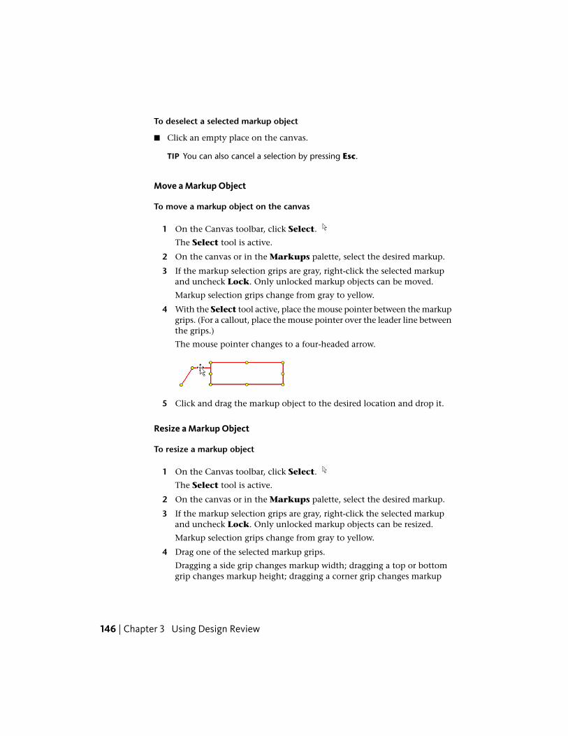
To deselect a selected markup object
■ Click an empty place on the canvas.
TIP You can also cancel a selection by pressing Esc.
Move a Markup Object
To move a markup object on the canvas
1 On the Canvas toolbar, click Select.
The Select tool is active.
2 On the canvas or in the Markups palette, select the desired markup.
3 If the markup selection grips are gray, right-click the selected markupand uncheck Lock. Only unlocked markup objects can be moved.
Markup selection grips change from gray to yellow.
4 With the Select tool active, place the mouse pointer between the markupgrips. (For a callout, place the mouse pointer over the leader line betweenthe grips.)
The mouse pointer changes to a four-headed arrow.
5 Click and drag the markup object to the desired location and drop it.
Resize a Markup Object
To resize a markup object
1 On the Canvas toolbar, click Select.
The Select tool is active.
2 On the canvas or in the Markups palette, select the desired markup.
3 If the markup selection grips are gray, right-click the selected markupand uncheck Lock. Only unlocked markup objects can be resized.
Markup selection grips change from gray to yellow.
4 Drag one of the selected markup grips.
Dragging a side grip changes markup width; dragging a top or bottomgrip changes markup height; dragging a corner grip changes markup
146 | Chapter 3 Using Design Review

width and height. As you drag a grip, press and hold Shift to maintainoriginal markup proportions.
See also:
Markups Palette (page 29)
About Callouts for 2D Content (page 158)
About Callouts for 3D Content (page 176)
About Markup Formatting Tools
Markup appearance can be changed using tools on the Formatting panelon the Markup & Measure tab. Custom symbols are the only markup objectsthat cannot be formatted in Design Review.
NOTE Locked markups can still be formatted.
Markup Formatting Tools
DescriptionTool
Text can be formatted using the Font Size, Text Color, and Boldtools.
Lines can be formatted using the Line Weight, Line Color, andLine Style tools.
Fill can be formatted using the Fill Color and Fill Transparencytools. The No Border tool can also be used to turn a markup objectborder on or off.
Markup DWF Files | 147

DescriptionTool
In addition to weight, color, and style, each line can also beformatted with a different Line Start Style and Line End Style.
Format Markups
Default markup settings, markup color, and markup line weight are the threeformatting methods shared by both 2D and 3D markups.
You can set the default formatting for a markup tool, so each new markup,whether a measurement or a callout, will have the same default formatting.Design Review retains markup formatting. You can also change the formattingof existing markups.
Format Markups
To set the default formatting for a markup tool
1 Verify that no markup objects are selected.
2 From the Callouts, Draw, Measure, or Stamps & Symbols panels,click the markup object type for which you want to set new defaultformatting.
3 In the Formatting panel, click a format tool to specify the type offormatting to be changed.
4 Select a format option to set the new formatting.
All new markup of the selected markup type will have this new formatting bydefault.
To format existing markups
1 On the Canvas toolbar, click Select.
The Select tool is active.
2 On the canvas or in the Markups palette, select the markup or markupsto reformat.
3 Click a format tool.
148 | Chapter 3 Using Design Review
4 Select a format option to apply to the selection.
The new formatting is applied to the selection.
NOTE Custom symbols cannot be formatted. They retain the formatting of theDWF file in which they were originally created.
Change the Font Size
Design Review enables you to change the font size of a markup object from1 pt to 72 pt. The default font size is 10 pt.
To change the font size
1 On the Canvas toolbar, click Select.
The Select tool is active.
2 On the canvas or in the Markups palette, select the desired text markupor markups.
3 Click Markup & Measure tab ➤ Formatting panel ➤ Font Size
drop-down list.
4 Select the desired font size.
The new font size is applied to the selection.
TIP You can also use different font sizes within the same text markup.
Set Color, Transparency, and Border Display
For all markup objects, you can control appropriate color settings:■ Text Color
■ Line Color
■ Fill Color
To set color
1 On the Canvas toolbar, click Select.
The Select tool is active.
2 On the canvas or in the Markups palette, select the desired markup ormarkups.
3 Click Markup & Measure tab ➤ Formatting panel.
Markup DWF Files | 149

4 Depending on the type of markup selected, click the Text Color
drop-down list , Line Color drop-down list , or Fill
Color drop-down list.
5 Select a pre-defined or custom color.
The new color is applied to the selection.
For callouts, closed shapes, and text boxes, you can also control fill colortransparency.
NOTE Rectangle clouds and polyclouds, although closed shapes, do not have fillcolors and must have borders.
To set transparency
1 On the Canvas toolbar, click Select.
The Select tool is active.
2 On the canvas or in the Markups palette, select the desired callout,closed shapes, or text box markup or markups.
3 Click Markup & Measure tab ➤ Formatting panel ➤ Fill
Transparency drop-down list.
4 Select the desired transparency percentage.
The new transparency is applied to the selection.
For callouts, closed shapes, and text boxes, you can also control whether ornot a border is shown.
To hide or show a markup border
1 On the canvas or in the Markups palette, select the desired markup ormarkups.
2 Click Markup & Measure tab ➤ Formatting panel.
3 Select the desired border display setting.■ To hide the markup border, check No Border.
■ To show the markup border, uncheck No Border.
The new border display setting is applied to the selection.
150 | Chapter 3 Using Design Review

Change the Line Weight
You can change the line thickness, or weight, of drawn shapes andmeasurement markups. The line weight range is between 1/4 pt and 20 pt.The default line weight thickness is 1 pt.
To change the line weight of a markup
1 On the Canvas toolbar, click Select.
The Select tool is active.
2 On the canvas or in the Markups palette, select the desired markup ormarkups.
3 On the ribbon, click the Markup & Measure tab ➤ Formatting
panel ➤ Line Weight drop-down list.
4 Select the desired line weight.
The new line weight is applied to the selection.
See also:
Change Default Color Options (page 250)
Change 2D Line Patterns (page 165)
Edit Text Markups
Using common editing methods—cut, copy, and paste—you can edit text inthree types of text markup: callouts, text boxes, and stamps.
Edit Text Markups
To edit text markups
1 On the Canvas toolbar, click Select.
The Select tool is active.
2 On the canvas, double-click the desired text markup.
3 Place the insertion point in the text markup and edit the text as needed.
4 To finish editing, click outside the text markup.
Markup DWF Files | 151

The edited text markup is shown on the canvas and in the Markupspalette.
TIP If you want a different label shown in the Markups palette than theone shown in the markup on the canvas, change the markup’s Label propertyin the Markup Properties palette.
See also:
About Callouts for 2D Content (page 158)
About Callouts for 3D Content (page 176)
Stamp a 2D Sheet (page 166)
Change Markup Properties (page 154)
Secure Markups (page 143)
Cut, Copy, Paste, and Delete Markup on the Canvas
You can cut, copy, and paste markups within the same sheet, between sheetsin the same DWF file, or between separate instances of Design Review. Cuttingor deleting markups removes the markup from both the canvas and theMarkups palette.
If no location is specified, pasting a copy of a markup (or a cut markup) withoutchanging the canvas view, slightly offsets the pasted markup from the original.Specify a new location by clicking anywhere on a sheet.
Pasting markup can have some noteworthy and unexpected results.■ If the markup object you paste is a dimension, the markup text (the
measurement) reflects the scale and units of measurement of the sheet towhich the dimension is pasted.
■ You cannot paste a markup copied from a 2D sheet on a 3D sheet, nor canyou paste a markup copied from a 3D sheet on a 2D sheet.
Paste Images on 2D Sheets
Images can be copied from any Windows application and pasted onto an open2D sheet in Design Review. (You cannot paste an image onto an open 3Dmodel.) After pasting, the image remains attached to the mouse pointer untilyou click to place it on the sheet. Once placed, the pasted image is treated likeany other drawn markup and listed in the Markups palette below the
152 | Chapter 3 Using Design Review
displayed 2D sheet as "Image 1". Subsequent pasted images are listedsequentially.
TIP Select pasted images and create your own custom symbol catalogs.
Cut, Copy, Paste, and Delete Markup on the Canvas
To cut or copy and paste a markup object
1 On the Canvas toolbar, click Select.
The Select tool is active.
2 On the canvas or in the Markups palette, select the desired markup.
3 If the markup selection grips are gray on the canvas, right-click theselected markup and uncheck Lock. Only unlocked markup objects canbe cut.
Markup selection grips change from gray to yellow.
4 Cut or copy the selected markup.■ Click Markup & Measure tab ➤ Clipboard panel ➤ Cut.
The selected markup is removed from the canvas and the Markupspalette and a copy is stored in memory.
■ Click Markup & Measure tab ➤ Clipboard panel ➤ Copy.
A copy of the selected markup is stored in memory.
5 Optional: Change the view, select a different sheet, or open anotherDWF file in a separate window to receive the copied markup.
6 Click where you want to paste the markup object.
7 Click Markup & Measure tab ➤ Clipboard panel ➤ Paste.
The markup is pasted to the selected location.
To delete a markup object
1 On the Canvas toolbar, click Select.
The Select tool is active.
2 On the canvas or in the Markups palette, select the desired markup.
3 If the markup selection grips are gray on the canvas, right-click theselected markup and uncheck Lock. Only unlocked markup objects canbe deleted.
Markup DWF Files | 153

Markup selection grips change from gray to yellow.
4 Right-click the selected markup and choose Edit ➤ Delete.
The markup is deleted from the Markups palette and the canvas.
TIP In the Markups palette, you can also right-click a markup and selectDelete.
See also:
Create a Symbol Catalog from a Selection (page 168)
Copy the Current View (page 230)
Change Markup Properties
In the Markup Properties palette, four properties can be changed for eachmarkup: Label, Lock Markup, Status, and New Note. After saving theDWF file, the changes are shown in the markup’s History the next time youopen the DWF file.
NOTE Markup properties can be changed even if a markup is locked.
Change Markup Properties
To change markup properties
1 In the Thumbnails or List View palette, select the sheet that containsthe markup whose properties you want to change.
2 Select the markup on the canvas or in the Markups palette.
3 Optional: In the Markup Properties palette, in the Label text box,select the current label text and type a new label for the markup.
When you select another markup property or tool, notice in theMarkups palette, that the selected markup label changes to the newlabel.
4 Optional: From the Status drop-down list, select a status.
Notice in the Markups palette, to the left of the markup name, the iconchanges from None to the desired status icon. The markup color alsochanges on the canvas to reflect its status.
154 | Chapter 3 Using Design Review

5 Optional: Check or uncheck Lock Markup to disallow or allow othermarkup modifications.
Notice in the Markups palette, to the left of the markup name, the lockicon changes to indicate the current locking state.
6 Optional: In the Markup Properties palette, in the New Note textbox, type the desired information.
IMPORTANT Before closing the DWF file, make sure that your note is editedthe way you want it. Existing notes are no longer editable once you reopena DWF file.
You can now save the DWF file and send it to someone else for revision ofthe drawing or continued exchange of markup and discussion.
See also:
Markup Status (page 29)
About Saving a DWF File (page 206)
Email an Open DWF File from Design Review (page 226)
Save a Summary of Markups
Design Review can create an accessible summary of all markups contained inthe open DWF file. Saved as a comma-separated value (CSV) file, the markupssummary can be shared and opened by a wide variety of database, spreadsheet,and word processor programs. The summary lists markups and their respectiveproperties.■ Markup number
■ Sheet name
■ Markup type
■ Markup label
■ Markup text
■ Creator
■ Created date and time stamp
■ Status
■ Modified date and time stamp
■ History
Markup DWF Files | 155

Save a Summary of Markups
To save a summary of markups
1 Click the application button ➤ Save As ➤ Save Markups Summary.
The Save Markups Summary dialog box opens.
TIP You can also save a summary by clicking Home tab ➤ File panel ➤ Save As drop-down list and selecting Save Markups Summary.
2 In the File Name text box, type the name of the file.
3 Optional: Navigate to the location where you want to store the file.
4 Click Save.
5 When notified that the markup summary was saved successfully, clickOK.
Markup 2D DWF Files
Snapping Markups to 2D Objects
Enabled by default, snaps are specific points on markup objects, except forfreehand shapes, drawings, or model geometry that behave like magnets.Snaps enable you to connect a markup object to another markup object or togeometry on a 2D sheet.
Design Review displays snaps as you move the mouse pointer over a markupobject, drawing, or model geometry. Snaps are located at key points and alongthe contour of the markup or geometry. The icon indicating a key snap point
is red with a white center. The icon indicating snap points along the contour
between key points is solid red.
156 | Chapter 3 Using Design Review

Snapping Markups to 2D Objects
To disable snapping markups to 2D objects
1 Click Home tab ➤ expand the View panel.
2 Uncheck Snap to Geometry.
Repeat these steps to re-enable snapping markups to 2D objects.
NOTE Snapping cannot be disabled for 3D markups.
Almost all types of markup can be snapped to the sheet or model content aswell as to other markup, with these exceptions: callouts with revision clouds,freehand markups, and custom symbols. However, these markup exceptionscan be snapped to by other markup.
To disconnect snaps
■ Drag one markup object away from another.
Snapping Priority
As a markup is drawn or dragged near an object, several snap points may benear each other. In this case, Design Review displays the snaps according tothe following priority:
1 Intersection
2 Endpoint, corner, midpoint, or center
3 Geometry
For example, if Snap to Geometry is enabled and you draw a Line shapetoward the intersection of two lines, the shape would snap to the intersectionof the lines rather than to the midpoint of one of the lines. Where snap settingshave the same priority, the snap target that is closer to the mouse pointer ischosen.
Markup DWF Files | 157

Callouts for 2D Content
About Callouts for 2D Content
Callout markups enable you to provide comments about 2D and 3D contentin the canvas area. All callouts have a callout text box and a leader line. Thecallout enables you to provide a textual comment or annotation about contenton the canvas. The leader line enables you to connect, or snap, the callout toan object on the canvas. Some callout markups have revision clouds. Revisionclouds help identify the part or parts of the drawing associated with a callouttext box.
The parts of a 2D markup callout: 1. revision cloud, 2. leader line, 3. callout text box
For 2D content, you have many more choices on the Callouts panel on theMarkup & Measure tab.
Callout Tools for 2D Content
DescriptionTool
Shaped callouts with no revision clouds. Use any of these three toolsto create a rectangle, circle, or triangle callout without a revisioncloud.
Shaped callouts with rectangle revision clouds. Use any of thesethree tools to create a rectangle, circle, or triangle callout with arectangular revision cloud.
Shaped callouts with polyclouds. Use any of these three tools tocreate a rectangle, circle, and triangle callout with a polygon revisioncloud.
See also:
Markup Basics (page 140)
158 | Chapter 3 Using Design Review

Create a Callout for 2D Content
The canvas view settings that are active at the time a markup is created areshown when a markup is selected.
WARNING When viewing a DWFx file in the Microsoft XPS Viewer, only markupsplaced completely on a sheet are shown. Markups that extend beyond the sheetare truncated.
To create a callout for 2D content
1 Open the DWF file that contains the 2D content you want to mark up.
2 Optional: Disable snaps (page 156).
3 Optional: Modify the canvas view settings by zooming and positioningthe contents on the canvas as desired.
4 Click Markup & Measure tab ➤ Callouts panel ➤ click the desiredcallout.
The mouse pointer changes to a crosshair.
■ To create a rectangle , circle , or triangle callout with norevision cloud, place the mouse pointer over the drawing where youwant to begin the leader line and click. Then drag the callout to thedesired location and click again to set the callout position.
■ To create a rectangle , circle , or triangle callout with arectangle revision cloud, place the mouse pointer over the drawingwhere you want to begin the revision cloud and click. Drag the mousepointer diagonally to surround the location associated with thecallout, and click again to finish the revision cloud and start theleader line. Then drag the callout to the desired location and clickagain to set the callout position.
■ To create a rectangle , circle , or triangle callout with a polygonrevision cloud, place the mouse pointer over the drawing where youwant to begin the revision cloud and click and drag the mousepointer. Click to create each segment of the polygon revision cloud,and either double-click the starting point of the polygon revisioncloud, or right-click the canvas to close the polygon revision cloud.
TIP You can constrain the angle of each polygon segment in 15°increments by pressing and holding Shift as you drag the mouse pointer.You can also press Backspace to delete the last segment you created.
Markup DWF Files | 159
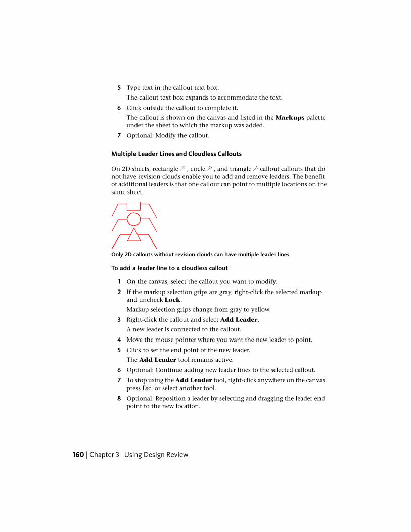
5 Type text in the callout text box.
The callout text box expands to accommodate the text.
6 Click outside the callout to complete it.
The callout is shown on the canvas and listed in the Markups paletteunder the sheet to which the markup was added.
7 Optional: Modify the callout.
Multiple Leader Lines and Cloudless Callouts
On 2D sheets, rectangle , circle , and triangle callout callouts that donot have revision clouds enable you to add and remove leaders. The benefitof additional leaders is that one callout can point to multiple locations on thesame sheet.
Only 2D callouts without revision clouds can have multiple leader lines
To add a leader line to a cloudless callout
1 On the canvas, select the callout you want to modify.
2 If the markup selection grips are gray, right-click the selected markupand uncheck Lock.
Markup selection grips change from gray to yellow.
3 Right-click the callout and select Add Leader.
A new leader is connected to the callout.
4 Move the mouse pointer where you want the new leader to point.
5 Click to set the end point of the new leader.
The Add Leader tool remains active.
6 Optional: Continue adding new leader lines to the selected callout.
7 To stop using the Add Leader tool, right-click anywhere on the canvas,press Esc, or select another tool.
8 Optional: Reposition a leader by selecting and dragging the leader endpoint to the new location.
160 | Chapter 3 Using Design Review

TIP You can also reposition the location where a leader bends, called theelbow, by dragging that elbow grip left or right.
To remove a leader line from a cloudless callout
1 On the canvas, select the callout you want to modify.
2 If the markup selection grips are gray, right-click the selected markupand uncheck Lock.
Markup selection grips change from gray to yellow.
3 Right-click the callout and select Remove Leader.
The mouse pointer changes to the Remove Leader tool.
4 Move the mouse pointer over the leader you want to remove.
5 Click the leader to remove it.
The Remove Leader tool remains active.
6 Optional: Continue removing leader lines from the selected callout.
7 To stop using the Remove Leader tool, right-click anywhere on thecanvas, press Esc, or select another tool.
See also:
Markups Palette (page 29)
Manipulate Markup Objects (page 145)
Edit Text Markups (page 151)
Change Markup Properties (page 154)
Create a Callout for 3D Content (page 176)
Secure Markups (page 143)
Learning Resources: Alternative Methods for Performing Commands (page262)
Markup DWF Files | 161

Draw 2D Markups
About 2D Drawing Markup Tools
You can draw shapes on 2D sheets using the tools on the Drawing panel.
NOTE You cannot draw shapes directly on a 3D sheet. You must first take asnapshot (page 137) of the 3D content.
2D Drawing Markup Tools
DescriptionTool
Line. Creates a line shape markup.
Polyline. Creates a polyline or polygon shape markup.
Freehand. Creates a freehand shape markup.
Rectangle. Creates a rectangle or square shape markup.
Ellipse. Creates an ellipse or circle shape markup.
Text Box. Creates a standalone text box markup. Unlike callouts,text box markups are not associated with a particular object on asheet.
Freehand Highlighter. Creates a freehand highlight shape markup.
Rectangle Highlighter. Creates a rectangle highlight shapemarkup.
Rectangle Cloud. Creates a leaderless rectangle or square cloudshape markup.
Polycloud. Creates a leaderless polycloud shape markup.
162 | Chapter 3 Using Design Review
Draw a 2D Markup
The canvas view settings that are active at the time a 2D markup is createdare those shown when a markup is selected.
Draw a 2D Markup
To draw a markup
1 Open the DWF file that contains the 2D content where you want todraw shapes.
2 Optional: Disable snaps. (page 156)
3 Optional: Modify the canvas view settings by zooming and positioningthe contents on the canvas as desired.
4 Click Markup & Measure tab ➤ Draw panel ➤ click the desireddrawing tool.
The mouse pointer changes to a crosshair.
■ To create a line shape , click to define the starting point, move themouse pointer, and click again to set the endpoint. Before settingthe endpoint, you can constrain a line angle to 15° increments bypressing and holding Shift.
■ To create a polyline shape , click to define the starting point, movethe mouse pointer, and click to create each segment. Press and holdShift to constrain the angle of each polyline segment to 15°increments. Press Backspace to delete the last polyline segmentcreated. Double-click to set the endpoint.
TIP You can also create a closed polygon by clicking the polyline shapestarting point. Once you close a polyline creating a polygon, it isautomatically filled with the current fill color.
■ To create a freehand shape , click and hold the left mouse buttonto define the starting point and drag to draw. Release the mousebutton to set the endpoint.
■ To create a rectangle shape , click to define the starting point, movethe mouse pointer, and click again to set the endpoint. Before settingthe endpoint, you can press and hold Shift while drawing a rectangleto create a square shape.
Markup DWF Files | 163

■ To create an ellipse shape , click to define the starting point, movethe mouse pointer, and click again to set the endpoint. Before settingthe end point, you can press and hold Shift while drawing an ellipseshape to create a circle shape.
■ To create a text box , you have two choices. You can click once tocreate a text box that is one character wide with a small margin, oryou can click and drag a text box to a desired size. Clicking oncecreates a text box with an undefined width; the text will not wrap.Clicking and dragging a text box diagonally sets the text box width,which will cause the text to wrap at the right border.
TIP By default, text boxes show no border. To show a border, clickMarkup & Measure tab ➤ Formatting panel uncheck No Borderto display a text box border.
■ To create a freehand highlight shape , click and hold the left mousebutton to define the starting point and drag to draw. Release themouse button to set the endpoint.
■ To create a rectangle highlight shape , click to define the startingpoint, move the mouse pointer, and click again to set endpoint.Before setting the endpoint, you can press and hold Shift whiledrawing a rectangle to create a square shape.
■ To create a rectangle cloud shape , click to define the starting point,move the mouse pointer, and click again to set the endpoint. Beforesetting the endpoint, you can also press and hold Shift while drawinga rectangular cloud to create a square cloud shape.
■ To create a polygon cloud shape , click to define the starting point,move the mouse pointer, and click to create each segment. Press andhold Shift to constrain the angle of each polyline segment to 15°increments. Press Backspace to delete the last segment created. Clickthe polygon cloud shape starting point to set the endpoint.
5 To stop using the selected drawing tool, press Esc or select another tool.
The markup is shown on the canvas and listed in the Markups paletteunder the sheet to which the markup was added.
6 Optional: Reposition or resize the markup.
See also:
Markup Basics (page 140)
164 | Chapter 3 Using Design Review

Change 2D Line Patterns
Unlike 3D markups, 2D markups can have different line patterns. Any 2Dlines (Line, Polyline, Freehand, Rectangle, Ellipse, Text Box, and leaderlines) can have line patterns applied.
NOTE Line patterns cannot be applied to markup revision clouds.
Change 2D Line Patterns
To change 2D line patterns
1 On the canvas or in the Markups palette, select the desired 2D markupor markups.
2 Click Markup & Measure tab ➤ Formatting panel ➤ Line Pattern
drop-down list.
3 Select the desired line pattern.
The Line Pattern is applied.
See also:
Format Markups (page 148)
Change 2D Line Start and End Styles
Unlike 3D markups, 2D markups can have different end styles for the startand end styles. Any 2D markup with lines (Freehand, Line, Polyline, andcallouts with leaders) can have arrow styles applied. Each line can have a
different Line Start Style and Line End Style .
NOTE Line start and end styles can be applied to locked or unlocked markupobjects.
Markup DWF Files | 165

Change 2D Line Start and End Styles
To change 2D line start and end styles
1 On the canvas or in the Markups palette, select the desired 2D markupor markups with lines or leaders.
2 Select a line start and end style.■ Click Markup & Measure tab ➤ Formatting panel ➤ Line Start
Style drop-down list and select the desired start style.
The Line Start Style is applied.
■ Click Markup & Measure tab ➤ Formatting panel ➤ Line End
Style drop-down list and select the desired end style.
The Line End Style is applied.
See also:
Format Markups (page 148)
Stamp a 2D Sheet
A stamp is a text markup you can add to a 2D sheet to indicate that sheet'sreview status. Some stamps include details provided by the computer, suchas your Windows user name and the date and time. Once placed, thesedynamic stamps become static and editable like any other markup.
Use stamps to indicate reviewing status
Dynamic stamps include current computer information
166 | Chapter 3 Using Design Review

Stamp a 2D Sheet
To stamp a 2D sheet
1 Open the DWF file that contains the 2D content you want to stamp.
2 Optional: Modify the canvas view settings by zooming and positioningthe contents on the canvas as desired.
3 Click Markup & Measure tab ➤ Stamps & Symbols panel
➤ Stamps drop-down.
4 Select the desired stamp.
5 On the 2D sheet, click where you want to position the lower, left cornerof the stamp.
The stamp is placed on the canvas and remains selected.
The stamp is shown on the canvas and listed in the Markups paletteunder the sheet to which the markup was added.
6 Optional: Reposition or resize the stamp.
7 Optional: Double-click the stamp to modify the text.
See also:
Markup Basics (page 140)
Use Symbols (page 167)
Manipulate Markup Objects (page 145)
Edit Text Markups (page 151)
Use Symbols
About Symbols
As a type of markup, symbols can be used and reused on any 2D sheet. Thebenefit of using this type of markup is the ability to access and consistentlyreuse common symbols.
In Design Review, custom symbols are stored in catalogs. These catalogs canbe made from selected 2D content. For example, you can create a new symbolcatalog from selected markup objects on 2D sheets. You can also import DWF
Markup DWF Files | 167

files and create a new catalog containing separate symbols from each object,or block, if the block template information was included in the DWF file whenit was published by a design application, such as AutoCAD. (For nested objects,only the top-level object is imported.) Another option when importing DWFfiles is to create a new catalog containing a separate symbol from each 2Dsheet in the DWF file, regardless of how many objects are on a sheet.
In addition to importing DWF files with drawings and text, you can also useDWF files with images or snapshots as symbols. Image types include:■ Sheets created by the Snapshot tool
■ JPEG (.jpg, .jpeg, .jpe, .jfif)
■ PNG (.png)
■ TIFF (.tif, .tiff)
The initial size of the symbol is determined by the dpi (page 278) suppliedwhen the image was created. If there is no dpi information in the source image,Design Review creates it at 150 dpi. If an image was created with a transparentlayer (called “alpha transparency”), the transparency is recognized in DesignReview.
The background of a custom symbol is transparent. Unlike stamps, symbolscannot be edited or formatted, and scale is ignored when converting DWFfiles to symbol catalogs.
See also:
Markup Basics (page 140)
Create a New 2D Sheet by Taking a Snapshot (page 137)
Create a Symbol Catalog from a Selection
To use custom symbols in Design Review, you can create a new symbol catalogfrom any selected object or objects on a 2D sheet. All selected objects becomea catalog available from the Symbols drop-down. The individual objects arearranged on the catalog submenu and can then be applied to 2D sheets inother DWF files.
168 | Chapter 3 Using Design Review

Create a Symbol Catalog from a Selection
To create a symbol catalog from a selection
1 With any 2D sheet open on the canvas, select the objects you want toinclude in your new symbol catalog.
2 Click Markup & Measurement tab ➤ Stamps & Symbols panel
➤ Symbols drop-down.
3 Click Create Catalog from Selection.
The Create Catalog from Selection dialog box opens.
4 In the Enter the Symbol Catalog Name text box, accept the defaultcatalog name or type a new name. Use a unique name for each catalog.Design Review prevents duplicate names. If you use the name of anexisting catalog, you are prompted to replace the existing catalog.
5 Click OK.
A message informs you about the successful catalog creation and howmany symbols it contains. The new catalog is added to the Symbolsdrop-down in alphabetical order, and each symbol is listed in a submenu.
See also:
Place a Symbol on a Sheet (page 171)
Cut Copy Paste and Delete Markup on the Canvas (page 152)
Manage Symbol Catalogs (page 172)
Create a Symbol Catalog from a DWF File
You can create a symbol catalog from DWF files containing 2D sheets andobjects. These sheets and objects become a catalog available from the Symbolsdrop-down. The individual items are arranged on the catalog submenu andcan then be applied to 2D sheets in other DWF files.
TIP If you are having trouble creating a symbol catalog from an older DWF file,you may need to update its DWF version. Open the older DWF file in DesignReview and save it to the latest DWF version. The updated DWF file can then beused to create a custom symbol catalog.
Markup DWF Files | 169

Create a Symbol Catalog from a DWF File
To import each object on a sheet as a symbol in a catalog, the block templateinformation must have been included in the DWF file when it was publishedby the design application. (For nested objects, only the top-level object isimported.)
To import each object on a sheet as a symbol in a catalog
1 With any 2D sheet open on the canvas, click Markup & Measure tab
➤ Stamps & Symbols panel ➤ Symbols drop-down.
2 Click Create Catalog from DWF.
The Create Catalog from DWF dialog box opens.
3 Navigate to where the DWF file that contains the symbols you want toimport is stored.
4 Select the DWF file and click Open.
The Create Catalog from DWF dialog box opens.
5 Accept the default catalog name or type a new name. Use a unique namefor each catalog. Design Review prevents duplicate names. If you use thename of an existing catalog, you are prompted to replace the existingcatalog.
6 Select Import Each Object on Sheets as a Symbol.
7 Click OK. If the DWF file is password-protected, a dialog box opensprompting for the password. Enter the password and click OK.
The Symbol Labels dialog box opens.
You can select a symbol label based on a published property or you canallow Design Review to apply an incremental catalog name to all symbols.If you select a symbol label based on a property name, each symbol willuse the property name associated with it when the object was published.If you cancel the Symbol Labels dialog box, incremental symbol labelsbased on catalog name will be given to the imported symbols. Forinstance, if the catalog is named Pipes, Design Review label each symbolPipes 1, Pipes 2, and so on.
8 Optional: From the Property Name drop-down list, select a propertyname to use for symbol labels.
9 Click OK.
170 | Chapter 3 Using Design Review

A message informs you about the successful catalog creation and howmany symbols it contains. The new catalog is added to the Symbolsdrop-down in alphabetical order, and each symbol is listed in a submenu.
To import each sheet as a symbol in a catalog
1 With any 2D sheet open on the canvas, click Markup & Measure tab
➤ Stamps & Symbols panel ➤ Symbols drop-down.
2 Click Create Catalog from DWF.
The Create Catalog from DWF dialog box opens.
3 Navigate to where the DWF file that contains the symbols you want toimport is stored.
4 Select the DWF file and click Open.
The Add Symbol Catalog dialog box opens.
5 Accept the default catalog name or type a new name. Use a unique namefor each catalog. Design Review prevents duplicate names. If you use thename of an existing catalog, you are prompted to replace the existingcatalog.
6 Select Import Each Sheet as a Symbol.
7 Click OK. If the DWF file is password-protected, a dialog box opensprompting for the password. Enter the password and click OK.
A message informs you about the successful catalog creation and howmany symbols it contains. The new catalog is added to the Symbolsdrop-down in alphabetical order, and each symbol is listed in a submenu.
See also:
Place a Symbol on a Sheet (page 171)
Manage Symbol Catalogs (page 173)
Place a Symbol on a Sheet
Once you have created a custom symbol catalog in Design Review, you canplace the custom symbols onto a 2D sheet.
Markup DWF Files | 171

Place a Symbol on a Sheet
To place a symbol on a sheet
1 Open the DWF file that contains the 2D content to which you want toadd the symbol.
2 Optional: Modify the canvas view settings by zooming and positioningthe contents on the canvas as desired.
3 Click Markup & Measure tab ➤ Stamps & Symbols panel
➤ Symbols drop-down.
4 Select the desired catalog and symbol.
5 On the 2D sheet, click where you want to position the center of thesymbol. The symbol is placed and remains selected.
The symbol is shown on the canvas and listed in the Markups paletteunder the sheet to which the markup was added.
6 Optional: Reposition or resize the symbol.
See also:
Stamp a 2D Sheet (page 166)
Manage Symbol Catalogs
Design Review enables you to rename, delete, export, and import customsymbol catalogs. Export your custom symbols as a symbol catalog file enablesyou to place the symbol catalog file in a central location or distribute it byemail. Team members and clients can then import the symbol catalog file,ensuring that they have symbols identical to your own.
NOTE You cannot remove an individual symbol directly from a catalog. You canonly delete an entire symbol catalog. To modify an existing symbol catalog, makea different selection or open an a modified DWF file and recreate the catalog usingthe same catalog name to overwrite the existing catalog.
172 | Chapter 3 Using Design Review

Manage Symbol Catalogs
To rename a symbol catalog
1 Click Markup & Measure tab ➤ Stamps & Symbols panel
➤ Symbols drop-down.
2 Click Manage Catalogs.
The Manage Catalogs dialog box opens.
3 From the Current Catalogs list, select the symbol catalog to berenamed.
4 Click Rename.
The previous catalog name is highlighted.
5 Type a new name and press Enter to change the name.
TIP Despite the order shown in the Current Catalogs list, the catalogs are listedalphanumerically on the Symbols drop-down. Rename symbol catalogs to achievethe desired list order.
To delete a symbol catalog
1 Click Markup & Measure tab ➤ Stamps & Symbols panel ➤
Symbols drop-down.
2 Click Manage Catalogs.
The Manage Catalogs dialog box opens.
3 From the Current Catalogs list, select the symbol catalog or catalogsto be deleted.
TIP Shift- or Ctrl-click to select multiple symbol catalogs.
4 Click Delete.
5 When prompted, "Are you sure you want to remove the selectedcatalogs?", click OK.
The symbol catalog is removed from the Current Catalogs list.
Markup DWF Files | 173

To export a symbol catalog
1 Click Markup & Measure tab ➤ Stamps & Symbols panel
➤ Symbols drop-down.
2 Click Manage Catalogs.
The Manage Catalogs dialog box opens.
3 From the Current Catalogs list, select the symbol catalog to beexported.
4 Click Export.
The Export Symbol Catalog dialog box opens.
5 Optional: Navigate to the location where you want to store a copy ofthe symbol catalog file.
6 Optional: In the File Name text box, type the name of the file.
7 Click Save.
To import a symbol catalog
1 Click Markup & Measure tab ➤ Stamps & Symbols panel
➤ Symbols drop-down.
2 Click Manage Catalogs.
The Manage Catalogs dialog box opens.
3 From the Current Catalogs list, select the symbol catalog to beimported.
4 Click Import.
The Import Symbol Catalog dialog box opens.
5 Navigate to where the symbol catalog you want to import is stored.
6 Select the symbol catalog file and click Open.
The imported symbol catalog is displayed in the Current Catalogs list.
See also:
Use Workspaces (page 38)
Share Design Review Options (page 252)
174 | Chapter 3 Using Design Review
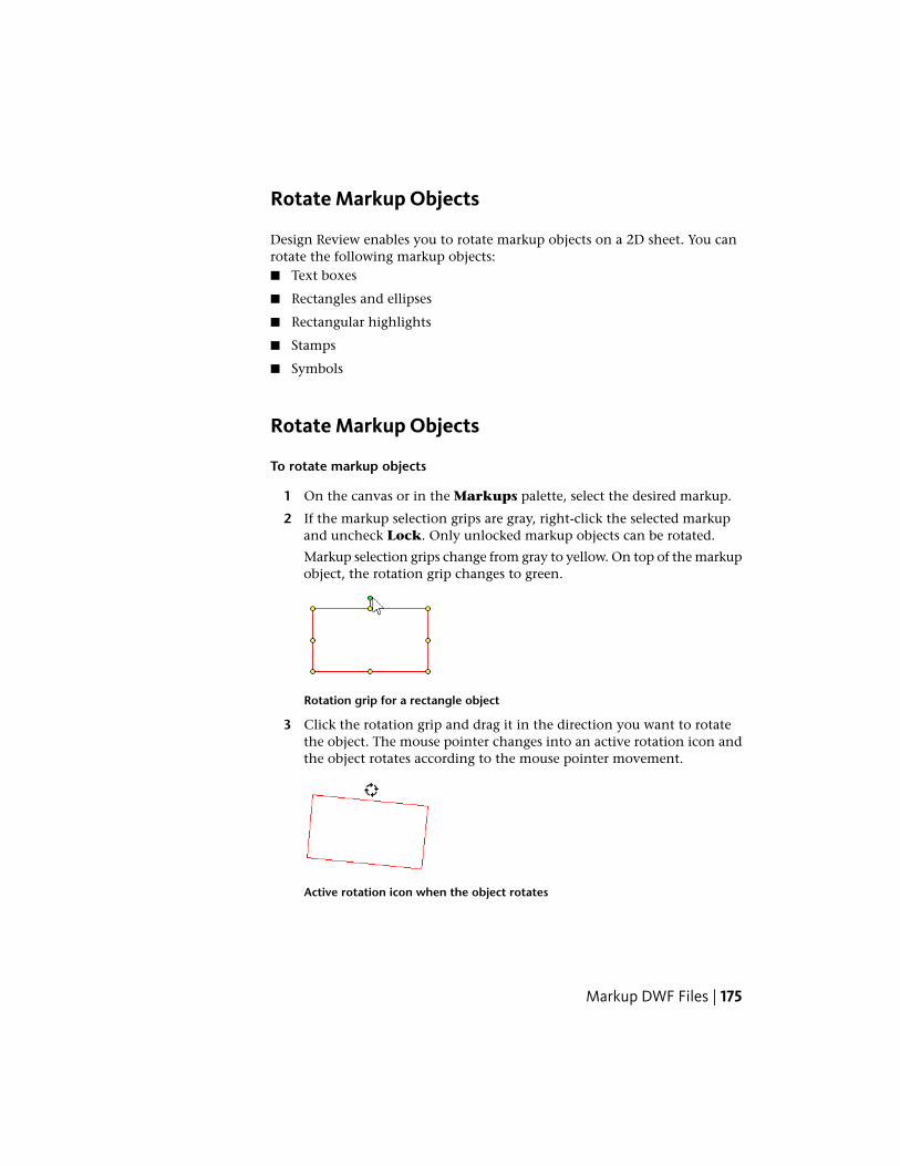
Rotate Markup Objects
Design Review enables you to rotate markup objects on a 2D sheet. You canrotate the following markup objects:■ Text boxes
■ Rectangles and ellipses
■ Rectangular highlights
■ Stamps
■ Symbols
Rotate Markup Objects
To rotate markup objects
1 On the canvas or in the Markups palette, select the desired markup.
2 If the markup selection grips are gray, right-click the selected markupand uncheck Lock. Only unlocked markup objects can be rotated.
Markup selection grips change from gray to yellow. On top of the markupobject, the rotation grip changes to green.
Rotation grip for a rectangle object
3 Click the rotation grip and drag it in the direction you want to rotatethe object. The mouse pointer changes into an active rotation icon andthe object rotates according to the mouse pointer movement.
Active rotation icon when the object rotates
Markup DWF Files | 175
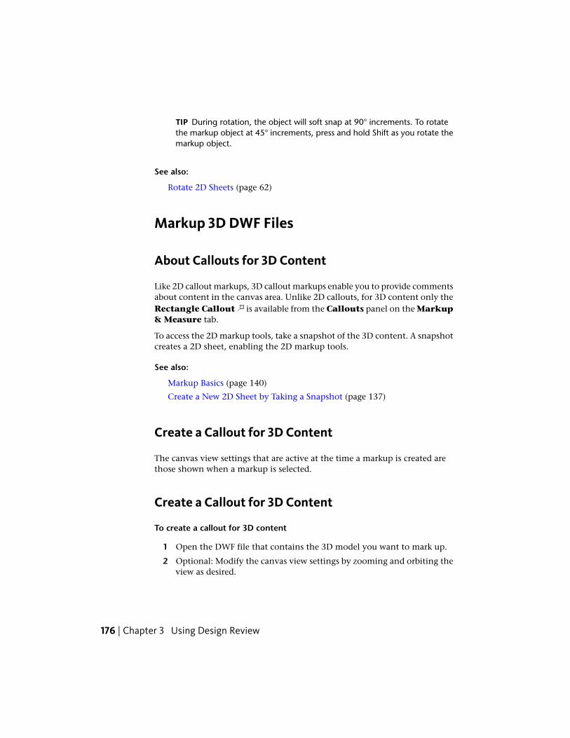
TIP During rotation, the object will soft snap at 90° increments. To rotatethe markup object at 45° increments, press and hold Shift as you rotate themarkup object.
See also:
Rotate 2D Sheets (page 62)
Markup 3D DWF Files
About Callouts for 3D Content
Like 2D callout markups, 3D callout markups enable you to provide commentsabout content in the canvas area. Unlike 2D callouts, for 3D content only theRectangle Callout is available from the Callouts panel on the Markup& Measure tab.
To access the 2D markup tools, take a snapshot of the 3D content. A snapshotcreates a 2D sheet, enabling the 2D markup tools.
See also:
Markup Basics (page 140)
Create a New 2D Sheet by Taking a Snapshot (page 137)
Create a Callout for 3D Content
The canvas view settings that are active at the time a markup is created arethose shown when a markup is selected.
Create a Callout for 3D Content
To create a callout for 3D content
1 Open the DWF file that contains the 3D model you want to mark up.
2 Optional: Modify the canvas view settings by zooming and orbiting theview as desired.
176 | Chapter 3 Using Design Review

3 Click Markup & Measure tab ➤ Callouts panel ➤ RectangleCallout.
The mouse pointer turns into a crosshair.
4 Place the mouse pointer over the model where you want to begin theleader line and click to set the leader line.
5 Move the mouse pointer to the location where you want to place thecallout text box and click again to set the callout text box position.
6 Type the text in the callout text box.
The callout text box expands to accommodate the text.
7 Click outside the callout to complete it.
The callout is shown on the canvas and listed in the Markups paletteunder the sheet to which the markup was added.
8 Optional: Modify the callout.
NOTE A 3D callout cannot have multiple leader lines.
See also:
Markups Palette (page 29)
Manipulate Markup Objects (page 145)
Edit Text Markups (page 151)
Change Markup Properties (page 154)
Create a Callout for 2D Content (page 159)
Secure Markups (page 143)
Learning Resources: Alternative Methods for Performing Commands (page262)
Measure Objects in DWF Files
About Measurements
Design Review enables you to add and save measurement markups for 2D and3D content using the Measure panel on the Markup & Measure tab. Likethe View panel on the Home tab, the Measure tab can be expanded to
Markup DWF Files | 177
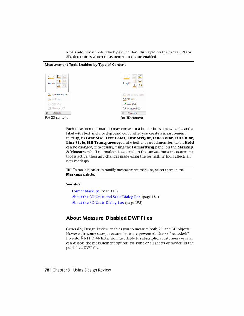
access additional tools. The type of content displayed on the canvas, 2D or3D, determines which measurement tools are enabled.
Measurement Tools Enabled by Type of Content
For 3D contentFor 2D content
Each measurement markup may consist of a line or lines, arrowheads, and alabel with text and a background color. After you create a measurementmarkup, its Font Size, Text Color, Line Weight, Line Color, Fill Color,Line Style, Fill Transparency, and whether or not dimension text is Boldcan be changed, if necessary, using the Formatting panel on the Markup& Measure tab. If no markup is selected on the canvas, but a measurementtool is active, then any changes made using the formatting tools affects allnew markups.
TIP To make it easier to modify measurement markups, select them in theMarkups palette.
See also:
Format Markups (page 148)
About the 2D Units and Scale Dialog Box (page 181)
About the 3D Units Dialog Box (page 192)
About Measure-Disabled DWF Files
Generally, Design Review enables you to measure both 2D and 3D objects.However, in some cases, measurements are prevented. Users of Autodesk®
Inventor® R11 DWF Extension (available to subscription customers) or latercan disable the measurement options for some or all sheets or models in thepublished DWF file.
178 | Chapter 3 Using Design Review
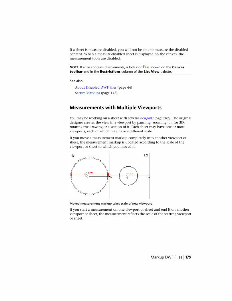
If a sheet is measure-disabled, you will not be able to measure the disabledcontent. When a measure-disabled sheet is displayed on the canvas, themeasurement tools are disabled.
NOTE If a file contains disablements, a lock icon is shown on the Canvastoolbar and in the Restrictions column of the List View palette.
See also:
About Disabled DWF Files (page 44)
Secure Markups (page 143)
Measurements with Multiple Viewports
You may be working on a sheet with several viewports (page 282). The originaldesigner creates the view in a viewport by panning, zooming, or, for 3D,rotating the drawing or a section of it. Each sheet may have one or moreviewports, each of which may have a different scale.
If you move a measurement markup completely into another viewport orsheet, the measurement markup is updated according to the scale of theviewport or sheet to which you moved it.
Moved measurement markup takes scale of new viewport
If you start a measurement on one viewport or sheet and end it on anotherviewport or sheet, the measurement reflects the scale of the starting viewportor sheet.
Markup DWF Files | 179
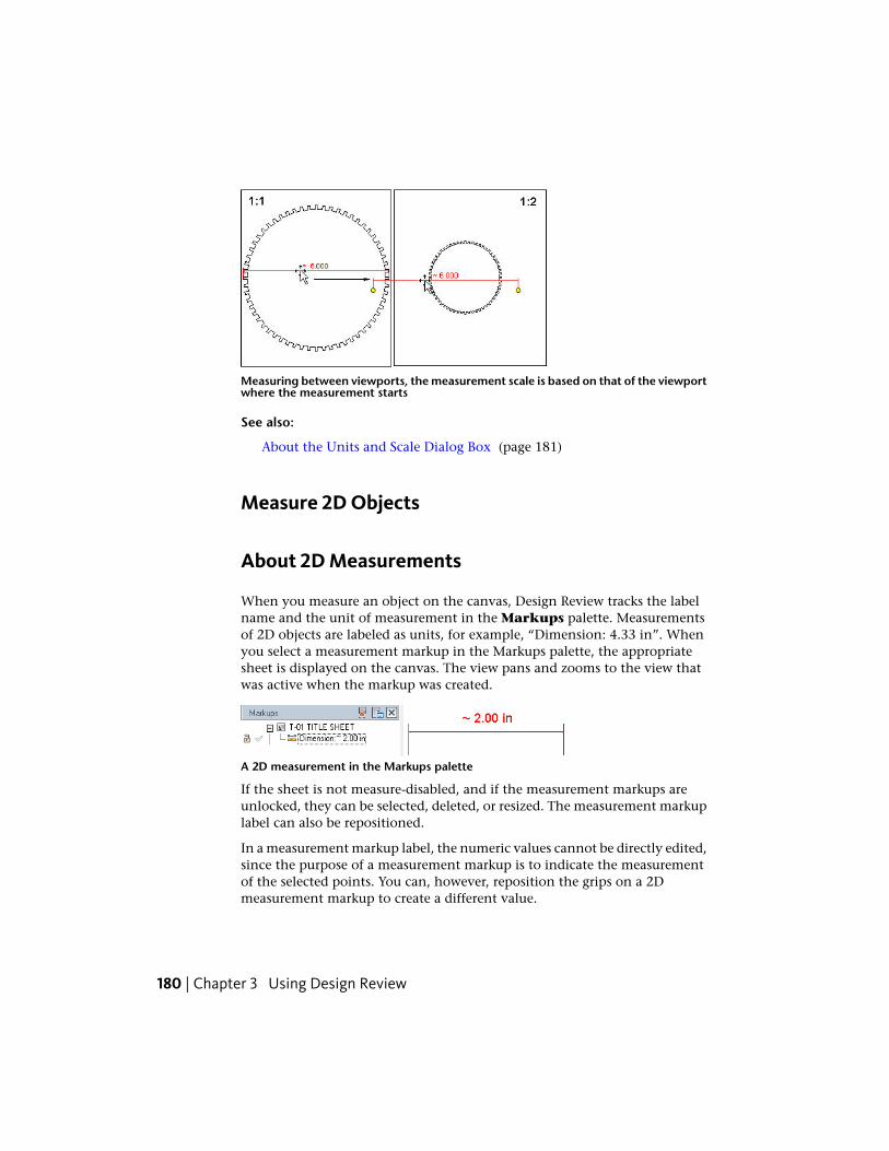
Measuring between viewports, the measurement scale is based on that of the viewportwhere the measurement starts
See also:
About the Units and Scale Dialog Box (page 181)
Measure 2D Objects
About 2D Measurements
When you measure an object on the canvas, Design Review tracks the labelname and the unit of measurement in the Markups palette. Measurementsof 2D objects are labeled as units, for example, “Dimension: 4.33 in”. Whenyou select a measurement markup in the Markups palette, the appropriatesheet is displayed on the canvas. The view pans and zooms to the view thatwas active when the markup was created.
A 2D measurement in the Markups palette
If the sheet is not measure-disabled, and if the measurement markups areunlocked, they can be selected, deleted, or resized. The measurement markuplabel can also be repositioned.
In a measurement markup label, the numeric values cannot be directly edited,since the purpose of a measurement markup is to indicate the measurementof the selected points. You can, however, reposition the grips on a 2Dmeasurement markup to create a different value.
180 | Chapter 3 Using Design Review

TIP You can also modify the markup label in the Markup Properties palette.
As you measure an object, the Object Highlighting settings on the Sheettab in the Options dialog box determine the colors.
See also:
About Measurements (page 177)
Markup Basics (page 140)
Sheet Tab (Options Dialog Box) (page 243)
About Precise 2D Measurements
The accuracy and precision of a measurement is affected by the resolutionand paper size of the original drawing, and the zoom at which you create themeasurement. You can ask the DWF file publisher to change the paper size(which will have a corresponding change to the drawing scale) or ask thepublisher to change the resolution (page 281) according to your needs. If youhave the DWG file, publish it at a higher resolution from DWG TrueView.Note, however, that using a higher dpi (page 278) setting will marginally increasethe DWF file size and may result in slower performance sharing the file,opening it, and changing the view.
In AutoCAD, the default publishing resolution for a DWF file is 1200 dpi. Thisresolution provides the same security as a printed drawing, from which itwould be challenging to recreate the original DWG file. You may thereforereceive a DWF file with a 6-inch length, which would be displayed as 5.98inches, for example. If you receive a measurement such as 5.98 for a lengththat you know should be a round number, you can pan and zoom in on ameasurement markup grip (page 279) to reposition it more precisely, so it displaysa round figure, such as 6.00.
About the 2D Units and Scale Dialog Box
The 2D Units and Scale dialog box enables you to control the precisiondisplayed by 2D measurement markups for each 2D sheet in the DWF file.Measurements can be in Imperial (feet and inches) or metric units.
In Design Review, the units and scale from the original drawing are used bydefault. However, if the original drawing did not specify units of measurement,only numeric values of the measurement are displayed in the resulting DWF
Markup DWF Files | 181
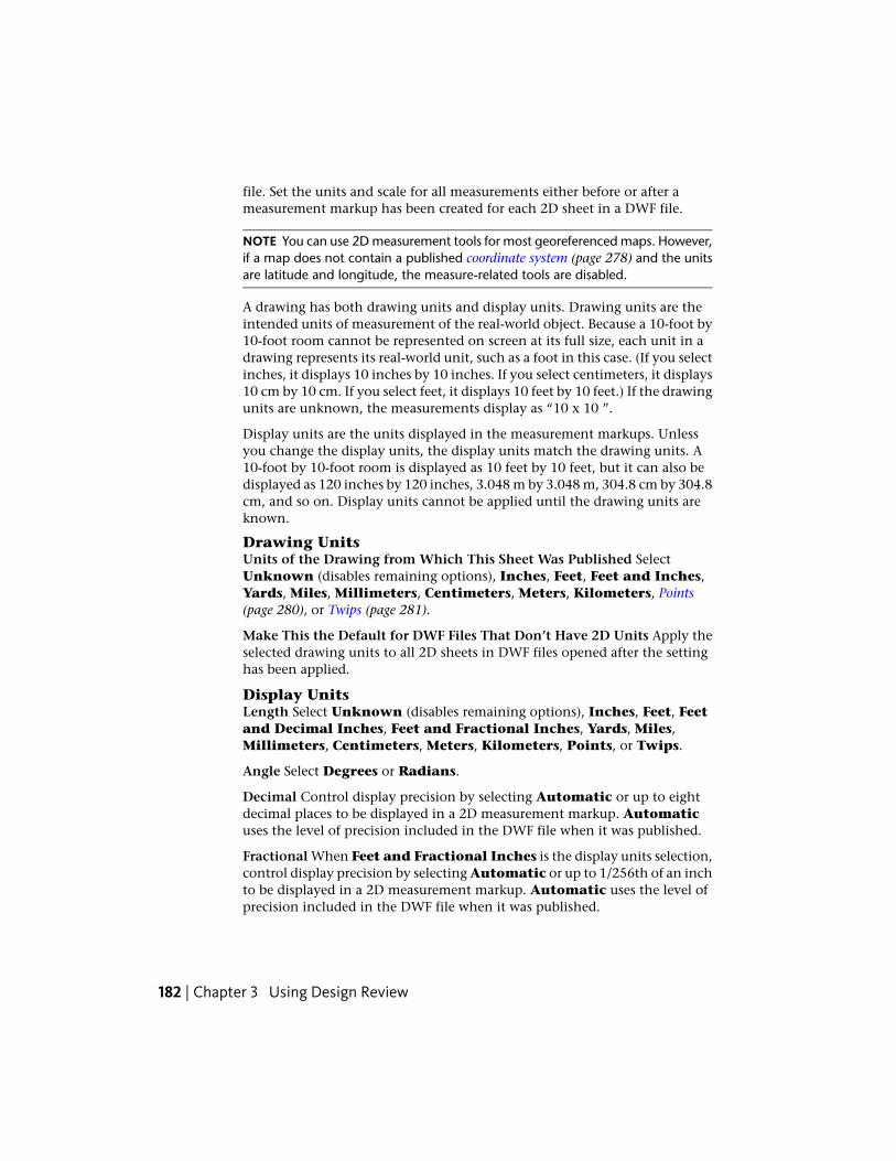
file. Set the units and scale for all measurements either before or after ameasurement markup has been created for each 2D sheet in a DWF file.
NOTE You can use 2D measurement tools for most georeferenced maps. However,if a map does not contain a published coordinate system (page 278) and the unitsare latitude and longitude, the measure-related tools are disabled.
A drawing has both drawing units and display units. Drawing units are theintended units of measurement of the real-world object. Because a 10-foot by10-foot room cannot be represented on screen at its full size, each unit in adrawing represents its real-world unit, such as a foot in this case. (If you selectinches, it displays 10 inches by 10 inches. If you select centimeters, it displays10 cm by 10 cm. If you select feet, it displays 10 feet by 10 feet.) If the drawingunits are unknown, the measurements display as “10 x 10 ”.
Display units are the units displayed in the measurement markups. Unlessyou change the display units, the display units match the drawing units. A10-foot by 10-foot room is displayed as 10 feet by 10 feet, but it can also bedisplayed as 120 inches by 120 inches, 3.048 m by 3.048 m, 304.8 cm by 304.8cm, and so on. Display units cannot be applied until the drawing units areknown.
Drawing UnitsUnits of the Drawing from Which This Sheet Was Published SelectUnknown (disables remaining options), Inches, Feet, Feet and Inches,Yards, Miles, Millimeters, Centimeters, Meters, Kilometers, Points(page 280), or Twips (page 281).
Make This the Default for DWF Files That Don’t Have 2D Units Apply theselected drawing units to all 2D sheets in DWF files opened after the settinghas been applied.
Display UnitsLength Select Unknown (disables remaining options), Inches, Feet, Feetand Decimal Inches, Feet and Fractional Inches, Yards, Miles,Millimeters, Centimeters, Meters, Kilometers, Points, or Twips.
Angle Select Degrees or Radians.
Decimal Control display precision by selecting Automatic or up to eightdecimal places to be displayed in a 2D measurement markup. Automaticuses the level of precision included in the DWF file when it was published.
Fractional When Feet and Fractional Inches is the display units selection,control display precision by selecting Automatic or up to 1/256th of an inchto be displayed in a 2D measurement markup. Automatic uses the level ofprecision included in the DWF file when it was published.
182 | Chapter 3 Using Design Review
Make This the Default for DWF Files That Don’t Have 2D Units Apply theselected drawing units to all 2D sheets in DWF files opened after the settinghas been applied.
ScaleScale If a scale was set when the DWF file was published, that scale is reflectedin the measurements displayed in Design Review. A 1-to-1 scale is displayedfor the open drawing. It shows 1" = 1" (1 inch equals 1 inch) for Feet andInches or 1:1 for metric scale, depending on whether the drawing was set inImperial (feet and inches) or metric.
If the published scale in the 2D sheet is incorrect or if you prefer a differentscale, you can apply one of the preset values from the Scale drop-down list.If you need a different scale from those provided, Custom Scale enables youto enter a custom value using the On Page and Actual options. For example,a 1" = 10' (1 inch equals 10 feet) custom scale designates that each inchdisplayed in the drawing represents 10 feet in the real world.
IMPORTANT Changing the published scale has these consequences.■ Viewport scales are overwritten. If the sheet contains one or more
viewports, the new scale is applied to the sheet and all viewports in thesheet. If the viewports had different scales, those scales are overwritten bythe new sheet scale.
■ Viewport measurement values are changed. If the sheet contains one ormore viewports with measurements, the new scale is applied to the sheet,all viewports in the sheet, and all measurements in the viewports. Thevalue of these re-scaled viewport measurements viewed in Autodesk DesignReview 2012 or later may be different if the same DWF file is viewed inprevious versions of Design Review.
Just after changing the scale, you can use Undo to return to the original scale.You can also revert to the original scale any time by selecting PublishedScale from the Scale drop-down list.
On Page Enter the value for measurements in the drawing.
Actual Enter the value you want measurements to represent in the real world.
See also:
Measurements with Multiple Viewports (page 179)
Markup DWF Files | 183

Set Precision for 2D Measurement Markups
To set precision for 2D measurement markups
1 Click Markup & Measure tab ➤ expand the Measure panel.
2 Select 2D Units & Scale.
The 2D Units and Scale dialog box opens.
3 In the Drawing Units area, from the Units of the Drawing fromwhich This Sheet Was Published drop-down list, select the desiredunits.
This setting is saved with the DWF file for the current sheet.
4 Optional: Click Make This the Default for DWF Files That Don’tHave 2D Units to have these units applied to all 2D sheets in DWFfiles after this setting has been applied.
5 In the Display Units area, from the Units to which Drawing UnitsWill Be Converted When Displaying Measurements drop-downlist, select the desired units.
This setting is saved with the DWF file for the current sheet.
6 Under Display Precision, from the Decimal drop-down list, selectthe number of decimal places to be displayed in a 2D measurementmarkup.
7 If Feet and Fractional Inches was selected in the Units to whichDrawing Units Will Be Converted When DisplayingMeasurements drop-down list, from the Fractional drop-down list,select up to 1/256th of an inch to be displayed in a 2D measurementmarkup.
8 Optional: Click Make This the Default for DWF Files That Don’tHave 2D Units to have these units applied to all 2D sheets in DWFfiles after this setting has been applied.
9 IMPORTANT If you plan to change the sheet's published scale, be sure toreview the consequences (page 183) first.
Optional: From the Scale drop-down list, select a scale.
If you select Custom Scale, enter the On Page and Actual values.
10 Click OK.
184 | Chapter 3 Using Design Review

Measurement Tools for 2D Objects
The measurement tools can be accessed from the Measure panel on theMarkup & Measure tab.
Measurement tools for 2D objects
The type of content displayed on the canvas, 2D or 3D, determines whichmeasurement tools are available on the Measure panel.
Measurement Tools for 2D Objects
DescriptionTool
Length. Measures the straight line distance between any two points.
Area. Measures the area of the traced polygon or rectangle.
Polyline. Measures the total cumulative length of multiple segments,including rectangles.
Angle. Measures angles between two connected lines or two non-parallel lines.
Snapping Measurements to 2D Objects
When measuring an object, the measurement tools for 2D content snap theresulting markup to that object. Snapping is especially important formeasurements, as the snap points determine the measurements displayed.Snaps are enabled by default.
Markup DWF Files | 185
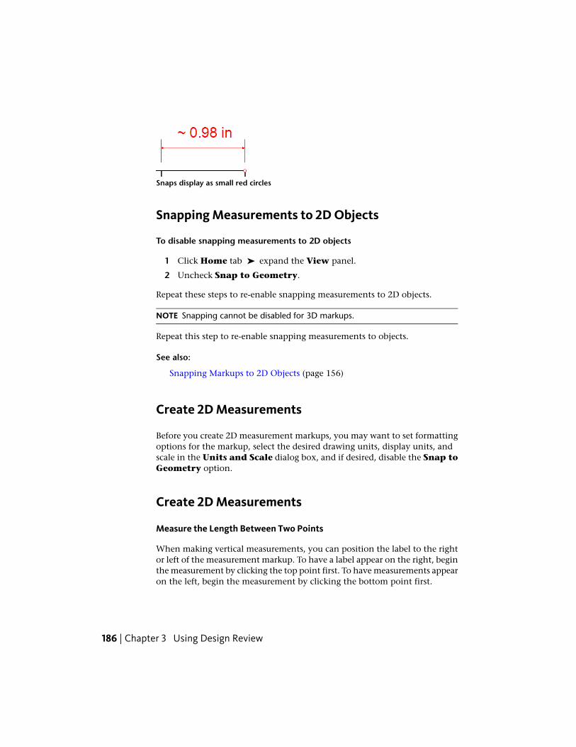
Snaps display as small red circles
Snapping Measurements to 2D Objects
To disable snapping measurements to 2D objects
1 Click Home tab ➤ expand the View panel.
2 Uncheck Snap to Geometry.
Repeat these steps to re-enable snapping measurements to 2D objects.
NOTE Snapping cannot be disabled for 3D markups.
Repeat this step to re-enable snapping measurements to objects.
See also:
Snapping Markups to 2D Objects (page 156)
Create 2D Measurements
Before you create 2D measurement markups, you may want to set formattingoptions for the markup, select the desired drawing units, display units, andscale in the Units and Scale dialog box, and if desired, disable the Snap toGeometry option.
Create 2D Measurements
Measure the Length Between Two Points
When making vertical measurements, you can position the label to the rightor left of the measurement markup. To have a label appear on the right, beginthe measurement by clicking the top point first. To have measurements appearon the left, begin the measurement by clicking the bottom point first.
186 | Chapter 3 Using Design Review

To measure the length between two points
1 Click Markup & Measure tab ➤ Measure panel ➤ Length.
2 On the sheet, place the mouse pointer where you want to begin themeasurement and click to set the start point.
3 Place the mouse pointer where you want to end the measurement andclick to set the end point.
The measurement markup displays the length in the chosen format andunits. A measurement appears in the Markups palette as Dimension:xxx.xxx units. The Length tool remains active for other measurements.
4 Optional: Make additional measurements.
5 To stop using the Length tool, press Esc or select another tool.
TIP Pressing Esc while measuring cancels the current measurement, butleaves the measuring tool active. Pressing Esc again cancels the Measuretool, making the Select tool active.
6 Optional: Modify the measurement markup position by clicking betweengrips and dragging the markup to a different location. You can also clickand drag markup start and end grips, but this changes the markup value.
After making horizontal Length measurements, the label always appearscentered above the measurement line. You can move this label horizontallyalong the measurement markup.
To move the label of a measurement markup
1 Select the desired measurement markup.
2 Place the mouse pointer over the middle grip and pause until the gripgets larger.
3 Click and drag the larger grip to the desired position along themeasurement markup.
TIP Drag the middle grip up or down to reposition the markup value relative tothe measurement.
Markup DWF Files | 187

Measure the Area of a Rectangle or Polygon
To measure the area of a rectangle or polygon
1 Click Markup & Measure tab ➤ Measure panel ➤ Area.
2 On the sheet, place the mouse pointer where you want to begin themeasurement and click to set the start point.
3 Click each subsequent corner point on the rectangle or polygon.
4 End the area measurement.■ Press Esc to end the area measurement at the last corner created.
■ Double-click to end the polyline measurement at the last pointclicked.
The measurement markup displays the area in the chosen format anddisplay units. A measurement appears in the Markups palette as“Dimension: xxx.xxx units”. The Area tool remains active for othermeasurements.
5 Optional: Make additional measurements.
6 To stop using the Area tool, press Esc or select another tool.
TIP Pressing Esc while measuring cancels the current measurement, butleaves the measuring tool active. Pressing Esc again cancels the measuretool, making the Select tool active.
7 Optional: Modify the measurement markup position by clicking betweengrips and dragging the markup to a different location. You can also clickand drag the markup grips, but this changes the markup value.
Measure the Length of a Polyline
A cumulative length tool, the Polyline tool displays the length of multiplelinear segments, including rectangles.
To measure the length of a polyline
1 Click Markup & Measure tab ➤ Measure panel ➤ Polyline.
188 | Chapter 3 Using Design Review

2 On the sheet, place the mouse pointer where you want to begin themeasurement and click to set the start point.
3 Click each subsequent point to be added to the polyline.
TIP To constrain a polyline measurement in 15°-increments, press and holdShift while rotating a polyline segment.
4 End the polyline measurement.■ Press Esc to end the polyline measurement at the last corner created.
■ Double-click to end the polyline measurement at the last pointclicked.
The measurement markup displays the cumulative length in the chosenformat and display units. A measurement appears in the Markupspalette as “Dimension: xxx.xxx units”. The Polyline tool remains activefor other measurements.
5 Optional: Make additional measurements.
6 To stop using the Polyline tool, press Esc or select another tool.
TIP Pressing Esc while measuring cancels the current measurement, butleaves the measuring tool active. Pressing Esc again cancels the measuretool, making the Select tool active.
7 Optional: Modify the measurement markup position by clicking betweengrips and dragging the markup to a different location. You can also clickand drag the markup grips, but this changes the markup value.
Measure a 2D Angle
The angle being measured depends on where you position the label. Forexample, when measuring a simple right angle, if the label is inside the angle,the measurement is 90°. However, if the label is outside the angle, themeasurement is 270°.
To measure a 2D angle
1 Click Markup & Measure tab ➤ Measure ➤ Angle.
Markup DWF Files | 189
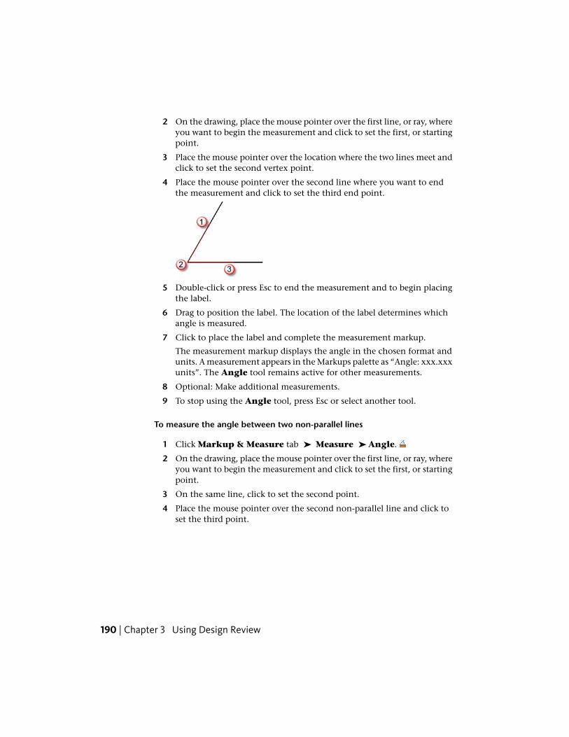
2 On the drawing, place the mouse pointer over the first line, or ray, whereyou want to begin the measurement and click to set the first, or startingpoint.
3 Place the mouse pointer over the location where the two lines meet andclick to set the second vertex point.
4 Place the mouse pointer over the second line where you want to endthe measurement and click to set the third end point.
5 Double-click or press Esc to end the measurement and to begin placingthe label.
6 Drag to position the label. The location of the label determines whichangle is measured.
7 Click to place the label and complete the measurement markup.
The measurement markup displays the angle in the chosen format andunits. A measurement appears in the Markups palette as “Angle: xxx.xxxunits”. The Angle tool remains active for other measurements.
8 Optional: Make additional measurements.
9 To stop using the Angle tool, press Esc or select another tool.
To measure the angle between two non-parallel lines
1 Click Markup & Measure tab ➤ Measure ➤ Angle.
2 On the drawing, place the mouse pointer over the first line, or ray, whereyou want to begin the measurement and click to set the first, or startingpoint.
3 On the same line, click to set the second point.
4 Place the mouse pointer over the second non-parallel line and click toset the third point.
190 | Chapter 3 Using Design Review

5 On the same line, click to set the fourth, or ending point.
6 Drag to position the label. The location of the label determines whichangle is measured.
7 Click to place the label and complete the measurement markup.
The measurement markup displays the angle in the chosen format andunits. A measurement appears in the Markups palette as “Angle: xxx.xxxunits”. The Angle tool remains active for other measurements.
8 Optional: Make additional measurements.
9 To stop using the Angle tool, press Esc or select another tool.
See also:
About Markup Properties (page 142)
Secure Markups (page 143)
Measure 3D Objects
About 3D Measurements
When you measure an object on the canvas, Design Review tracks the labelname and the unit of measurement in the Markups palette. Measurementsof 3D objects are labeled based on the type of measurement being performedand the value is displayed as “xxx.xx units”, for example “Diameter: 1.50 in”.The units are determined by the Display Units chosen for the open sheet.When you select a measurement markup in the Markups palette, theappropriate sheet is displayed on the canvas, and the view pans and zoomsto the view that was active when the markup was created.
Markup DWF Files | 191
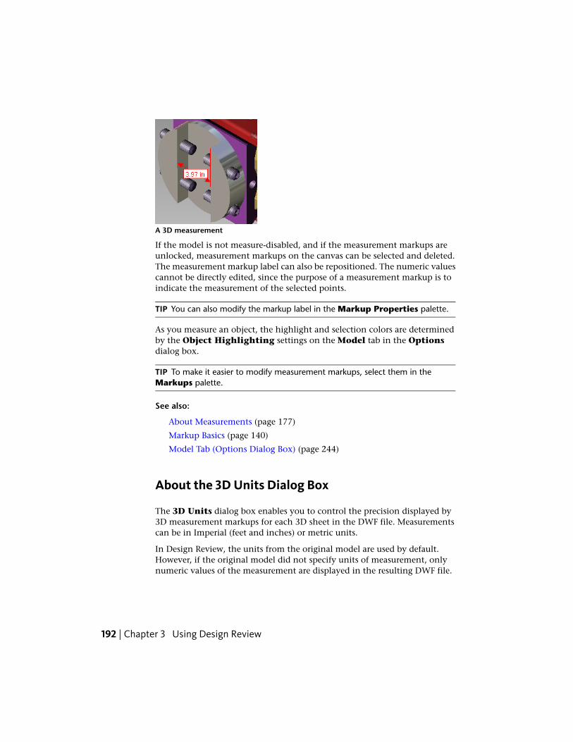
A 3D measurement
If the model is not measure-disabled, and if the measurement markups areunlocked, measurement markups on the canvas can be selected and deleted.The measurement markup label can also be repositioned. The numeric valuescannot be directly edited, since the purpose of a measurement markup is toindicate the measurement of the selected points.
TIP You can also modify the markup label in the Markup Properties palette.
As you measure an object, the highlight and selection colors are determinedby the Object Highlighting settings on the Model tab in the Optionsdialog box.
TIP To make it easier to modify measurement markups, select them in theMarkups palette.
See also:
About Measurements (page 177)
Markup Basics (page 140)
Model Tab (Options Dialog Box) (page 244)
About the 3D Units Dialog Box
The 3D Units dialog box enables you to control the precision displayed by3D measurement markups for each 3D sheet in the DWF file. Measurementscan be in Imperial (feet and inches) or metric units.
In Design Review, the units from the original model are used by default.However, if the original model did not specify units of measurement, onlynumeric values of the measurement are displayed in the resulting DWF file.
192 | Chapter 3 Using Design Review
You may set the units for all measurements yourself either before or after ameasurement markup has been created for each 3D sheet in a DWF file.
Display UnitsUnits for 3D Length Measurements Select Unknown (disables DisplayPrecision options), Inches, Feet, Feet and Decimal Inches, Feet andFractional Inches, Yards, Miles, Millimeters, Centimeters, Meters,or Kilometers.
Units for 3D Angle Measurements Select Degrees or Radians.
Make This the Default for DWF Files That Don’t Have 3D Units If checked,the Display Units settings is the default for DWF files that do not alreadyhave published Display Units.
Display PrecisionDecimal Control display precision by selecting Automatic or up to eightdecimal places to be displayed in a measurement markup. Automatic usesthe level of precision included in the DWF file when it was published.
Fractional When Feet and Fractional Inches is the display units selection,control display precision by selecting Automatic or up to 1/256th of an inchto be displayed in a 3D measurement markup. Automatic uses the level ofprecision included in the DWF file when it was published.
Precision settings are used for all DWF files viewed on this computer.
Set Precision for 3D Measurement Markups
A model only has display units. Display units are the units displayed in 3Dmeasurement markups on the canvas and in the Markups palette.
Set Precision for 3D Measurement Markups
To set precision for 3D measurement markups
1 Click Markup & Measure tab ➤ expand the Measure panel.
2 Select 3D Units.
The 3D Units dialog box opens.
3 In the Display Units area, from the Units for 3D LengthMeasurements drop-down list, select the desired units.
This setting is saved with the DWF file for the current sheet.
Markup DWF Files | 193
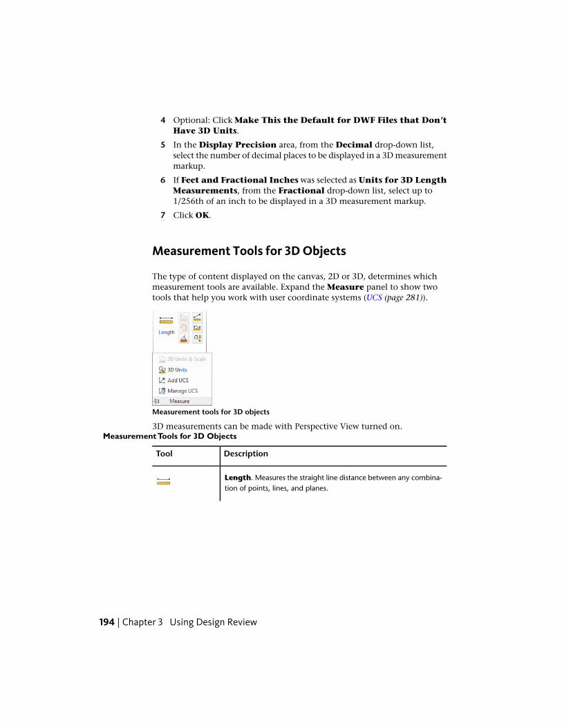
4 Optional: Click Make This the Default for DWF Files that Don’tHave 3D Units.
5 In the Display Precision area, from the Decimal drop-down list,select the number of decimal places to be displayed in a 3D measurementmarkup.
6 If Feet and Fractional Inches was selected as Units for 3D LengthMeasurements, from the Fractional drop-down list, select up to1/256th of an inch to be displayed in a 3D measurement markup.
7 Click OK.
Measurement Tools for 3D Objects
The type of content displayed on the canvas, 2D or 3D, determines whichmeasurement tools are available. Expand the Measure panel to show twotools that help you work with user coordinate systems (UCS (page 281)).
Measurement tools for 3D objects
3D measurements can be made with Perspective View turned on.Measurement Tools for 3D Objects
DescriptionTool
Length. Measures the straight line distance between any combina-tion of points, lines, and planes.
194 | Chapter 3 Using Design Review

DescriptionTool
Angle. Measures angles between lines and lines, lines and planes,and planes and planes.
Relative Distance. Measures distance along a direction defined bysome other edge of the model.
Length/Radius. Measures edge length, the radius of an arc, or thediameter of a circle with a single click. Radius measurements arepreceded by the radius symbol (R). Diameter measurements are
preceded by the diameter symbol ( )
Point Location. Locates the X,Y,Z location of points on a model,
measured relative to the currently active coordinate system (page278).
See also:
About Measure-Disabled DWF Files (page 178)
About Coordinate Systems (page 196)
Use Perspective View (page 64)
Markup DWF Files | 195

About Coordinate Systems
A coordinate system is a method used to indicate object position indimensional space. By default, when a sheet containing 3D content is displayedon the canvas in Design Review, the World Coordinate System (WCS (page282)) is active and the Y axis points upward. You can define additionalcoordinate systems, called User Coordinate Systems (UCS (page 281)), for eachsheet that contains a 3D model. The origin and axes of a UCS are relative tothe WCS. Each UCS enables you to set up a point of reference for a particularset of point location measurements, and is represented by a new tripod at thedefined location on the model.
Both the world and user coordinate systems are represented by tripods. Eachtripod axis is color coded: the X axis is red; the Y is axis green; and the Z axisis blue. These tripods can be hidden or displayed as needed.
User coordinate systems allow point location measurements to be taken inthe context in which they are used in the real world. For example, whenlocating a hole for machining, real world measurements are taken with respectto edges of the part, not to an abstract WCS.
Since the frame of reference may be different at various places on the samemodel, multiple UCSs can be created. However, only one coordinate systemcan be active at the once. The active coordinate system tripod is the largeston the canvas. Inactive coordinate systems tripods are reduced in size.
Each UCS is listed in the Markups palette order in which it was created. If apoint location measurement has been added to a UCS, it is listed below itsrespective UCS in the Markups palette.
When you create and activate a UCS, a drop-down list is displayed under theViewCube. From this list, you can quickly select a different coordinate systemor open the Manage Coordinate Systems dialog box to change the settingsof an existing UCS or create other coordinate systems.
See also:
Show or Hide Coordinate System Tripods (page 201)
Use the ViewCube (page 72)
About the Manage Coordinate Systems Dialog Box
The Manage Coordinate Systems dialog box enables you to copy,manipulate, and delete user coordinate systems for the sheet displayed on the
196 | Chapter 3 Using Design Review
canvas. The World Coordinates is read only. It cannot be moved, modified,or deleted, as indicated by the lock icon displayed to the left of WorldCoordinates in the Available Coordinate Systems list.
Available Coordinate SystemsAvailable Coordinate Systems Lists the WCS and all UCSs in the order theywere created.
Activate Makes the selected coordinate system active.
Copy Makes a copy of the selected coordinate system.
Delete Deletes the selected UCS.
Selected Coordinate System PositionLocation of Origin in World Coordinates Current position of the selectedUCS origin in relation to the origin of the WCS.
X. Enter a value, either positive or negative, to change the X coordinate ofthe selected UCS origin relative to the WCS.
Y. Enter a value, either positive or negative, to change the Y coordinate of theselected UCS origin relative to the WCS.
Z. Enter a value, either positive or negative, to change the Z coordinate of theselected UCS origin relative to the WCS.
Axis Directions Flip X Axis. Flips current X axis 180°.
Flip Y Axis. Flips current Y axis 180°.
Flip Z Axis. Flips current Z axis 180°.
Offset Selected Coordinate SystemMove Selected Coordinate System from Current Location by X. Type thenumber of units to move the origin relative to the X axis.
Y. Type the number of units to move the origin relative to the Y axis.
Z. Type the number of units to move the origin relative to the Z axis.
Display Coordinate Systems on Top Displays coordinate systems in front of3D objects.
Add a User Coordinate System
In Design Review, you can add a user coordinate system to a 3D model directly.When adding a UCS, camera tools, like Orbit, can be used during themeasurement process, in case you must reposition the model.
Markup DWF Files | 197
To begin adding a UCS, you can click either a point or an edge of a 3D model.If you first click a point, or vertex, on a model, this sets the origin of the UCStripod. The next two clicks define the X and Y axes. If you click a model edgefirst, this sets the X axis. The next click defines the Y axis. The Z axis is setautomatically.
After adding a new UCS, it becomes the active coordinate system.
Add a User Coordinate System
To add a UCS directly to a point on a 3D model
1 Click Markup & Measure tab ➤ expand the Measure panel.
2 Click Add UCS.
The mouse pointer changes to a crosshair.
3 On the model, place the mouse pointer over the point where you wantto begin creating the UCS and click to set the origin.
4 Optional: To position the model so you can see where you want to beginsetting the UCS, expand and pin the Measure panel, use the desiredcamera tool, and click the Add UCS again to resume adding the UCS.
5 On the model, place the mouse pointer over the next point or edgewhere you want to define the X axis and click to set the X axis.
6 On the model, place the mouse pointer over the next point or edgewhere you want to define the Y axis and click to set the Y axis.
The UCS tripod is displayed on the canvas and listed in the Markupspalette. Placing the mouse pointer over a UCS shows its name in a screentip.
To add a UCS directly to an edge on a 3D model
1 Click Markup & Measure tab ➤ expand the Measure panel.
2 Click Add UCS.
The mouse pointer changes to a crosshair.
3 On the model, place the mouse pointer over the edge where you wantto begin creating the UCS and click to set the X axis.
4 Optional: To position the model so you can see where you want to beginsetting the Y axis, expand and pin the Measure panel, use the desiredcamera tool, and click the Add UCS again to resume adding the UCS.
198 | Chapter 3 Using Design Review

5 On the model, place the mouse pointer over the next point or edgewhere you want to define the Y axis, and click to set the Y axis.
The UCS tripod is displayed on the canvas and listed in the Markupspalette. Placing the mouse pointer over a UCS shows its name in a screentip.
Manage Coordinate Systems
The Manage Coordinate Systems dialog box enables you to manage allcoordinate-system related actions, including activating, copying, renaming,and deleting user coordinate systems.
NOTE The WCS is read only. It cannot be moved, modified, or deleted, as indicatedby the lock icon in the Manage Coordinate Systems dialog box.
Manage Coordinate Systems
Activate a Coordinate System
Before you can add point location measurements to a coordinate system, youmust first activate it.
To activate a coordinate system
1 Click Markup & Measure tab ➤ expand the Measure panel.
2 Click Manage UCS.
The Manage Coordinate Systems dialog box opens.
3 From the Available Coordinate Systems list, select the coordinatesystem to be activated.
4 Click Activate.
5 Click Apply to activate the UCS and leave the Manage CoordinateSystems dialog box open, or click OK to activate the UCS and close theManage Coordinate Systems dialog box. Clicking Close beforeclicking either Apply or OK, closes the dialog box, but does not activatethe user coordinate system.
TIP You can also activate an existing UCS by selecting it or one of its markupsin the Markups palette, by clicking either the markup or the UCS on thecanvas, or by selecting the UCS from the drop-down list below the ViewCube.
Markup DWF Files | 199

Copy a Coordinate System
From the Manage Coordinate Systems dialog box, you can make a copyof the WCS or of another UCS.
NOTE You can manage the location of a selected UCS in relation to the WCS, flipthe axes of a selected UCS, and offset the position of a selected UCS at any time.
To copy a coordinate system
1 Click Markup & Measure tab ➤ expand the Measure panel.
2 Click Manage UCS.
The Manage Coordinate Systems dialog box opens.
3 From the Available Coordinate Systems list, select the coordinatesystem to be copied.
4 Click Copy.
A copy of the selected coordinate system is added to the list.
5 Optional: Under Location of Origin in World Coordinates, enterX, Y, and Z values to change the location of the selected user coordinatesystem origin away from the WCS.
6 Optional: Under Axis Directions, check the axis or axes you want toflip.
7 Optional: Under Offset User Coordinates, enter X, Y, and Z valuesto move the selected user coordinate system from its current location.
8 Click Apply to apply changes to the copied UCS and leave the ManageCoordinate Systems dialog box open, or click OK to apply changesto the copied UCS and close the Manage Coordinate Systems dialogbox. Clicking Close before clicking either Apply or OK, closes the dialogbox, but does not apply any changes to the copied UCS.
Rename a User Coordinate System
When you add or copy a UCS, it is named “User coordinates n”, where “n” isa number that is one greater than the highest number currently listed. Youcan rename a UCS at any time.
To rename a user coordinate system
1 Click Markup & Measure tab ➤ expand the Measure panel.
2 Click Manage UCS.
200 | Chapter 3 Using Design Review

The Manage Coordinate Systems dialog box opens.
3 From the Available Coordinate Systems list, double-click the usercoordinate system to be renamed. The UCS name text box becomesactive.
4 Type the new name for the UCS and press Enter.
5 Click Apply to rename the UCS and leave the Manage CoordinateSystems dialog box open, or click OK to rename the UCS and close theManage Coordinate Systems dialog box. Clicking Close beforeclicking either Apply or OK, closes the dialog box, but does not renamethe user coordinate system.
Delete a User Coordinate System
When you delete a UCS, all point location measurements associated with theUCS are also deleted.
WARNING Deleting a UCS deletes all markup that was created while thatcoordinate system was active.
To delete a user coordinate system
1 Click Markup & Measure tab ➤ expand the Measure panel.
2 Click Manage UCS.
The Manage Coordinate Systems dialog box opens.
3 From the Available Coordinate Systems list, select the user coordinatesystem to be deleted.
4 Click Delete.
5 Click Apply to delete the UCS and leave the Manage CoordinateSystems dialog box open, or click OK to delete the UCS and close theManage Coordinate Systems dialog box. Clicking Close beforeclicking either Apply or OK, closes the dialog box, but does not deletethe user coordinate system.
TIP In the Markups palette or on the canvas, right-click the UCS you wantto delete and click Delete.
Show or Hide Coordinate System Tripods
By default, all coordinate system tripods are hidden on the canvas. However,you can show them as desired.
Markup DWF Files | 201

To show or hide coordinate system tripods on the canvas
1 Click Home tab ➤ expand the View panel.
2 Check Coordinate Systems.
The coordinate system tripods are shown on the canvas.
TIP Right-click the canvas and choose Show ➤ Coordinate Systems.
Repeat these steps to hide coordinate systems.
Repeat this step to restore the coordinate system tripods.
Create 3D Measurements
Before you create 3D measurement markups, you may want to set formattingoptions for the markups and select the desired display units and precisionsettings for the label text in the Units dialog box. Unlike 2D measurementmarkups, snapping is always enabled when creating 3D measurements.
Create 3D Measurements
Measure the Distance Between Two Points
To measure the distance between two points
1 Click Markup & Measure tab ➤ Measure ➤ Length.
2 On the canvas, place the mouse pointer where you want to begin themeasurement and click to set the start point.
3 Optional: Using the ViewCube, the Orbit tool, or any other 3D viewtools position the model so you can see where you want to set themeasurement end point.
Click Length again to resume measuring.
4 Place the mouse pointer where you want to end the measurement andclick to set the end point.
5 Drag to position the label and click to complete the measurementmarkup.
202 | Chapter 3 Using Design Review

The measurement markup displays the distance between the two pointsin the chosen format and units. A measurement appears in the Markupspalette as “Length: xxx.xxx units”. The Length tool remains active forother measurements.
TIP If the measurement lines are obscured by an object, the lines are dashed.
6 Optional: Make additional measurements.
7 To stop using the Length tool, press Esc or select another tool.
8 Optional: Click and drag the label along the measurement markup toreposition it.
Measure the Distance from a Point to the Origin of a Coordinate System
To measure the distance from a point to the origin of a coordinate system
1 Optional: In the Markups palette, select the desired UCS to make itactive. If no UCS is selected or available, the current coordinate systemis used.
2 Click Markup & Measure tab ➤ Measure ➤ Point Location.
3 On the model, place the mouse pointer where you want to create thepoint location measurement and click to set the point.
TIP To view the measurement value without adding a measurement markup,press Esc to cancel the point location measurement.
4 Drag the label to the desired location and click to place the label.
The measurement markup displays the distance of the point from theselected coordinate system in the chosen format and units. Ameasurement appears in the Markups palette as “Location: X: xxx.xxxunits Y: xxx.xxx units Z: xxx.xxx units”. The Point Location tool remainsactive for other measurements.
TIP If the measurement lines are obscured by an object, the lines are dashed.
5 Optional: Make additional measurements.
6 To stop using the Point Location tool, press Esc or select another tool.
7 Optional: Modify the measurement markup label position by clickingand dragging it to a new location.
Markup DWF Files | 203

Measure Distance Along a Direction Defined by an Edge
To measure distance along a direction defined by an edge
1 Click Markup & Measure tab ➤ Measure ➤ Relative Distance.
2 Click a model edge, two vertices, or an axis on a coordinate system tripodto set a reference direction for the measurement.
3 On the model, place the mouse pointer where you want to begin therelative measurement and click to set the start point.
4 Optional: Using the ViewCube, the Orbit tool, or any other 3D viewtools position the model so you can see where you want to set themeasurement end point.
Click Relative Distance again to resume measuring.
5 Place the mouse pointer where you want to end the measurement andclick to set the end point.
6 Drag to position the label and click to complete the measurementmarkup.
The measurement markup displays the distance between the two points,relative to the set reference point in the chosen format and units. Ameasurement appears in the Markups palette as “Relative Length: xxx.xxxunits”. The Relative Distance tool remains active for other measurements.
TIP If the measurement lines are obscured by an object, the lines are dashed.
7 Optional: Make additional measurements.
8 To stop using the Relative Distance tool, press Esc or select anothertool.
9 Optional: Click and drag the label along the measurement markup toreposition it.
Measure the Length/Radius of an Object
The Length/Radius tool can measure the length of a line, the radius of an arc,or the diameter of a circle.
To measure the length of a line, radius of an arc, or diameter of a circle
1 Click Markup & Measure tab ➤ Measure ➤ Length/Radius.
2 On the model, place the mouse pointer over the object to be measured:■ Click a line to measure its length.
204 | Chapter 3 Using Design Review

■ Click an arc to measure its radius.
■ Click the center of a circle to measure its diameter.
3 Optional: Using the ViewCube, the Orbit tool, or any other 3D viewtools position the model so you can see where you want to place thelabel.
Click Length/Radius again to resume measuring.
4 Drag to position the label and click to complete the measurementmarkup.
The measurement markup displays the measurement in the chosenformat and units. A measurement appears in the Markups palette as“Length: xxx.xxx units”, “Radius: xxx.xxx units”, or “Diameter: xxx.xxxunits”. The Length/Radius tool remains active for other measurements.
TIP If the measurement lines are obscured by an object, the lines are dashed.
5 Optional: Make additional measurements.
6 To stop using the Length/Radius tool, press Esc or select another tool.
7 Optional: Click and drag the label along the measurement markup toreposition it.
Measure a 3D Angle
The angle being measured depends on where you position the label. Forexample, when measuring a simple right angle, if the label is inside the angle,the measurement is 90°. However, if the label is outside the angle, themeasurement is 270°.
To measure a 3D angle
1 Click Markup & Measure tab ➤ Measure ➤ Angle.
2 On the model, place the mouse pointer over the line or plane where youwant to begin the measurement and click to set the first, or startingpoint.
3 Optional: Using the ViewCube, the Orbit tool, or any other 3D viewtools position the model to show other areas of the model that you maywant to include in the measurement.
Click Angle again to resume measuring.
4 Place the mouse pointer over the line or plane where you want to endthe measurement and click to set the end point.
Markup DWF Files | 205

NOTE If the measurement lines are obscured by an object, the lines aredashed.
5 Drag to position the label. The location of the label determines whichangle is measured.
6 Click to complete the measurement markup.
The measurement markup displays the angle in the chosen format andunits. A measurement appears in the Markups palette as “Angle: xxx.xxxunits”. The Angle tool remains active for other measurements.
7 Optional: Make additional measurements.
8 To stop using the Angle tool, press Esc or select another tool.
9 Optional: Click and drag the label to select a different, associated angle.
See also:
About Markup Properties (page 142)
Secure Markups (page 143)
Save DWF Files
About Saving a DWF File
Saving a new file in Design Review uses the default file type. You can changethe default file format in the Options dialog box.
Saving or renaming an existing DWF file retains the original file format whenit was opened. You can change the file type each time you save from the Saveas Type drop-down list in the Save File dialog box.
If you anticipate that your DWFx files will be viewed using the Microsoft XPSViewer, be aware that the XPS file format only supports JPEG, PNG, and TIFFimage files from Design Review. So when saving a DWF file as a DWFx file,any images not supported by the XPS format are converted automatically andstored in the resulting DWFx file as PNG images.
WARNING If a DWFx file contains disablements, it cannot be saved as a DWF file.The DWFx file with disablements must be republished as a DWF file from theoriginating design program.
206 | Chapter 3 Using Design Review

About Saving an Open PDF as a DWF File
Design Review cannot save an open PDF file in the Adobe PDF file format. Ifyou modify an open PDF file, you must save it as a DWF file to retain themodifications. When saving the PDF file as a DWF file, the PDF content issaved as raster images. You can specify the resolution of the raster images onthe PDF Conversion tab in the Options dialog box before saving. Theoriginal PDF file remains unchanged.
Save DWF Files
To save a new, rename an existing, or save an existing file as another file type
1 Click the application button ➤ Save As ➤ Save as DWFx/DWF.
The Save File dialog box opens.
WARNING Re-saving a digitally signed DWFx file, invalidates the digitalsignature.
2 Optional: Navigate to the location where you want to store the file.
3 In the File Name text box, type the name of the file.
4 Optional: From the Save as Type drop-down list, select the desired fileformat.
5 Click Save.
NOTE If no changes have been made to the open DWF file, Save is disabled.
To save changes to an existing DWF file
■ Click the application button ➤ Save.
Changes are saved, overwriting the original file.
TIP You can also click the Save button on the Quick Access toolbar.
WARNING Saving changes to a digitally signed DWFx file, invalidates the digitalsignature.
See also:
File Notifications (page 242)
Save DWF Files | 207

Warn When Upgrading Earlier Versions of DWF (page 242)
About a Digital Signature (page 210)
Save a Summary of Markups (page 155)
About Resolution (page 48)
About Opening PDF Files (page 46)
PDF Conversion Tab (Options Dialog Box) (page 250)
Save a DWF File to Buzzsaw
Autodesk® Buzzsaw® can help your organization centralize project-relateddocuments, simplify communication, and streamline collaboration. Whensaving a DWF file from Design Review to Buzzsaw, the original file format isretained by default. If the file is a DWF file, it is saved to Buzzsaw as a DWFfile. If a file is a DWFx file, it is saved to Buzzsaw as a DWFx file.
NOTE When you save a file to Buzzsaw, your Buzzsaw user name, rather than yourWindows login name becomes the author property of the file.
Save a DWF File to Buzzsaw
To save a DWF file to Buzzsaw
1 In Design Review, save any modifications you have made to the openfile.
2 Click the application button ➤ Save As ➤ Save to Buzzsaw.
3 Enter your User Name, Password, and the Site.
TIP You can also have Design Review remember your Buzzsaw password.
4 Click OK.
5 Optional: Navigate to the location where you want to store the DWFfile.
6 Optional: In the File Name text box, type the name of the file.
7 Click Save.
8 After the file has been transferred successfully to the Buzzsaw site, clickOK.
208 | Chapter 3 Using Design Review

See also:
Open a DWF File from Buzzsaw (page 52)
Save a DWF File to Freewheel
The Autodesk® Project Freewheel website allows you to view and collaboratewith design data without installing additional software. The ability to save aDWF file to the Autodesk Project Freewheel website for online reviewing hassome prerequisites:■ An active Internet connection
■ The Autodesk® Freewheel Add-in must be installed
■ An Autodesk Consolidated Login user ID and password
With an active Internet connection, the first time you click the applicationbutton ➤ Save As ➤ Save to Freewheel, a browser window opens, offeringyou an opportunity to download and install the Freewheel Add-in. The nexttime, when you save to Freewheel, you will be prompted register or to signin, if you already have a user ID and password.
IMPORTANT Save to Freewheel requires an active Internet connection.
Save a DWF File to Freewheel
To save a DWF file to Freewheel
1 Open the DWF file you want to save to Freewheel.
2 Click the application button ➤ Save As ➤ Save to Freewheel.
The Publish to Freewheel dialog box opens. You are prompted toaccept the Terms of Use.
3 Click OK.
A browser window opens and you may be prompted to log in.
4 Enter your User ID, Password, and click Submit.
The DWF file is shown in a browser window.
Save DWF Files | 209

See also:
Get Design Review Add-ins (page 132)
Sign DWFx Files
About a Digital Signature
A digital signature (page 278) is a method used to maintain file authenticity andto provide a safe environment for sending and receiving data. A digitalsignature provides several benefits.■ The signature in a DWFx file informs the viewer if the file has been altered
or saved since it was signed.
■ The digital signature has a copy of the certificate used to sign the DWFxfile, so the certificate and associated information can be viewed in DesignReview.
A digital signature is not the same as a digitized signature. While a digitalsignature helps prove your identity and file authenticity, a digitized signatureis nothing more than an electronic version of your own hand-written signature.A digitized signature can be forged and copied, and has no real security value.
Before you can add a digital signature to a file, you must have a valid publickey certificate, or certificate, typically issued by a certificate authority, installedon your computer. A certificate contains a name, serial number, expirationdate, and other information that certifies the digital signature. For moreinformation about obtaining a certificate, search the Web for “digitalcertificate”.
About Certificates
Certificates work on a trust hierarchy, or chain. In a trust hierarchy, the rootcertificate is the certificate of the issuing certificate authority. Browsers, suchas Microsoft Internet Explorer, already include the root certificates of themajor certificate vendors, making those certificates automatically trusted.
Before you can digitally sign a DWFx file, you must first have certificateinstalled on your computer. Similarly, when you receive a DWFx file thatcontains a digital signature from a certificate authority that is not recognizedby your computer, for example, a certificate issued by your company's internalIT department, you need to install the sender’s root certificate before you can
210 | Chapter 3 Using Design Review

determine if the certificate in the digital signature is valid. To learn how toinstall a certificate, search the Windows Help file for “certificate”.
Add a Digital Signature to a DWFx File
Design Review2013 can be used to digitally sign DWFx files. Only the DWFxfile format supports digital signatures. The DWF file format does not supportdigital signatures. When attempting to digitally sign a DWF file, you areprompted to save it as a DWFx file.
If a DWF file contains markup-, measure-, or printing-disablements, it cannotbe converted from the DWF to DWFx file format in Design Review.Consequently, it is not possible to sign disabled DWF files. The DWF file withdisablements must be republished as a DWFx file from the originating designprogram before it can be signed using Design Review.
Digitally signed DWFx files can only be viewed in Design Review 2013. Ifrecipients have an older version of Design Review, these versions do notrecognize that the DWFx file was digitally signed.
NOTE Add Digital Signature is not available when viewing an embedded DWFxfile. However, you can view digital signature details by clicking the digital signatureicon in the Canvas toolbar.
In some cases, an older version of Design Review may present a warning dialogbox, but the message does not specifically identify that the DWFx file wasdigitally signed. It only indicates that the file contains an unsupported feature.Whether or not a warning is shown, the file still opens. As a result, therecipients using an older version of Design Review may unknowingly savechanges to the signed file, invalidating the digital signature. Before youdistribute a digitally signed file, notify recipients they need to upgrade to thelatest version of Design Review to retain the valid digital signature.
WARNING The Microsoft XPS Viewer does not support digitally signed DWFx files.
Working with Digitally Signed DWFx Files
Once you have a digitally signed DWFx file open, you can view it like anyother file, but modifying the DWFx file content in any way invalidates theoriginal digital signature if you re-save the file. The next person to open thatDWFx file is notified that the original digital signature is invalid, suggestingthat the DWFx file was modified since it was originally signed.
Sign DWFx Files | 211

Add a Digital Signature to a DWFx File
NOTE Before digitally signing a DWFx file, you must have a digital certificateinstalled.
To add a digital signature to a DWFx file
1 If necessary, open the DWFx file you want to digitally sign.
2 Click the application button ➤ Security ➤ Add Digital Signature.
If the DWFx file is already digitally signed, click Yes to continue.
The Add a Digital Signature dialog box opens.
3 Select a valid certificate.
4 Optional: View the certificate information. To return to the Add aDigital Signature dialog box, click OK.
5 To digitally sign the DWFx file, click OK.
If prompted to save the file as a DWFx file, click Yes to continue.
The View Signature Details dialog box opens.
6 Click OK.
On the Canvas toolbar, a digital signature icon indicates the DWFxfile was signed successfully.
Re-sign a DWFx File
After you sign a DWFx file, you may need to make additional modificationsto the same file before offering it to others. Saving changes invalidates yourfirst signature, so you need to sign the DWFx file again.
See also:
About DWF and DWFx (page 1)
About Disabled DWF Files (page 44)
Limitations of Embedded DWF Files (page 235)
212 | Chapter 3 Using Design Review

View Digital Signature Details
When a DWFx file contains a digital signature, upon opening the file, theView Signature Details dialog box opens showing information about thesignature.■ Validity of the digital signature
■ Whether or not the file was modified since signing
■ A summary pertaining to the certificate used to sign the file
NOTE Click View Certificate for more details about the certificate.
■ The name of the person or organization that signed the file
Once a digitally signed DWFx file is open, a digital signature icon is also shownon the Canvas toolbar.
A digital signature may be valid or invalid. A digital signature may be invalidif the file was modified after it was digitally signed.
View Digital Signature Details
To view digital signature details of a signed DWFx file
1 Open the View Digital Signature dialog box.■ Open a digitally signed DWFx file.
■ Click the application button ➤ Security ➤ View Signature
Details.
■ On the Canvas toolbar, click the digital signature icon.
The View Signature Details dialog box opens, showing whether ornot the digital signature is valid, whether or not the file has beenmodified since being signed, and who signed the DWFx file.
2 Optional: For more details, click View Certificate. The Certificatedialog box opens, showing additional details.
When done viewing details, click OK.
3 Click OK to close the View Signature Details dialog box.
Sign DWFx Files | 213

Print Files
About Print-Disabled DWF Files
In addition to disabling measurement and markup, designers using Autodesk®
Inventor® 2008 or later can prevent some or all sheets in a published DWFfile from being printed. If the DWF file contains sheets that are notprint-disabled, the Print command is enabled even when a print-disabledsheet is shown on the canvas.
NOTE If a file contains disablements, an icon is shown on the Canvas toolbar (
) and in the Restrictions column ( ) of the List View palette.
See also:
About Disabled DWF Files (page 44)
About the Print Dialog Box
The Print dialog box enables you to control all Design Review printingoptions.
PrinterName From the Name drop-down list, select an available printer. Afterselecting a printer, more information about that printer is shown. Statusshows the condition of the selected printer. Type shows information aboutthe selected printer. Location, if available, shows physical locationinformation about the selected printer. Comments, if available, shows notesand details about the selected printer.
Properties Click Properties to open a dialog box provided by the selectedprinter manufacturer. See the manufacturer Help for information about aspecific printer.
NOTE Some manufacturer printer properties can conflict with properties definedin Design Review. If so, the last option that you selected (whether in Design Reviewor in the manufacturer print dialog box) is applied.
Always Use This Printer Select to make the printer in the Name drop-downlist the default printer used by Design Review. If left unselected, Design Review
214 | Chapter 3 Using Design Review

will revert back to using the system default printer the next time Design Reviewstarts.
Use HP Instant Printing Only available if you select an HP printer with InstantPrinting capabilities from the Name drop-down list. Opens the HP InstantPrinting dialog box.
Print to File Creates a file, in a format that contains raw printing data, whichyou can print from a command prompt. You cannot open the file.
PaperSize Select a paper size from the drop-down list. If the printer changes, thatprinter’s default paper size is selected.
Print RangeAll Prints all sheets in the file. All is enabled only when Full Page is selectedin the View drop-down list.
View Full Page prints the complete drawing, regardless of what is seen onscreen. Current View prints the view on the canvas when the Print dialogbox was invoked.
Current Sheet Only Prints only the sheet currently shown on the canvas.
Pages From Type a list of sheets separated by commas (1, 5, 7) or a range ofsheets separated by a hyphen (1-7). If the print range contains one or moreprint-disabled pages, a dialog box opens listing the print-disabled content.Pages From is enabled only when Full Page is selected.
Page HandlingCopies Select the number of copies you want to print.
Collate Determine how multiple copies are printed. Collate is enabled onlywhen more than one copy is selected.
Reverse Order If you have selected multiple sheets, select Reverse Order toprint the last sheet first.
Choose Paper Source by DWF Page Size Prints the file at a size that bestmatches the DWF size when it was published. Choose Paper Source byDWF Page Size is unavailable when printing 3D models.
Scaling and Alignment (2D Only)Fit to Page Fits the drawing to the chosen paper size reducing or increasingthe scale accordingly.
Scale You can scale sheets as a percentage relative to the published sheet size,choose real-world scales from a drop-down list of values, or enter a Customscale. The Custom Scale dialog box enables you to enter the number ofinches (or millimeters) equal to the number of drawing units.
Print Files | 215

Tile Pages Tile Pages prints the sheets across several pieces of paper. Scalemust be selected to enable this option.
Clip Pages When a drawing has been scaled, it may not fit to the pageprecisely. Clip Pages positions the printed pages according to the selectedalignment. Scale must be selected to enable this option.
OrientationPortrait Prints the longest side vertically.
Landscape Prints the longest side horizontally.
Print ColorSheets Specify a color setting for the file. Color prints the sheets and modelsin color. Black and White prints the 2D sheets in black and white and the3D models in grayscale. Grayscale prints the sheets and models in shades ofgray. This color setting only affects printing colors. It does not affect howcontent is shown on the canvas.
Markups Specify a color setting for the markups. Color prints the markupsin color. Black and White prints the markups in black and white. Grayscaleprints the markups in shades of gray. This color setting only affects printingcolors. It does not affect how markups are shown on the canvas.
PreviewPreview Shows a preview of the open file with details, such as Original Size,Paper Size, Print (shows the Print RangeView), and Zoom for the currentview of 2D sheets. Use the buttons below the Preview area to display othersheets and models to be printed. Print Range determines which sheets areshown in the Preview area.
AdvancedPre-process Bitmaps In the Advanced Print Options dialog box, in thePre-process Bitmaps group. Select Turn Data into a Bitmap BeforePrinting if experiencing printer or output issues for 2D content. Considerthis setting if the content being printed contains gradients or a high numberof drawn objects, markups, or images. This setting does not affect 3D content.
Resolution Depending on the printer selected, Automatic uses the defaultprint quality and the User Defined drop-down list provides specific dpivalues or a list of generic quality presets, such as Draft, Low, Medium orHigh. Reducing the resolution may improve printing speed. If Design Reviewcannot determine these printer capabilities, Resolution options are disabled.
Color Quality By default, Color Quality will be set to High for highestoutput quality. Reducing the color quality may improve printing speed.
216 | Chapter 3 Using Design Review

Advanced print settings only affect raster files and only persist for the currentsession. When you exit Design Review, your Advanced print settings arediscarded.
See also:
Instant Printing with HP Printers (page 220)
Print to File (page 219)
Print an Open File
You can print one or more sheets from an open DWF file. You also can printdifferent views of the sheets and models, and preview your pages beforeprinting.
Unless you select a new paper size, 3D models print on a default paper size.The model is matched to the orientation that fits it best, portrait or landscape,and then printed as it appears on screen. Viewing choices made, such as zoom,object visibility, and cross sections are also printed.
Once the desired printing options have been set, you can use the Quick Printtool to send the open file directly to the printer. Quick Print uses the existingprint settings, bypassing the Print dialog box.
Print an Open File
To print an open DWF file
1 Optional: If you want to print the Current View, prepare the view sothat it appears on the canvas the way you want it printed.
NOTE If statuses have been added to callout markups, you can controlwhether or not the markup status colors are printed in the Options dialogbox, on the General tab, by changing the Use Markup Status ColorHighlighting option.
2 Click the application button ➤ Print ➤ Print.
The Print dialog box opens.
TIP You can also click the Print button on the File panel and the Quick
Access toolbar.
Print Files | 217

3 Optional: Select printing options.
4 Optional: Below the Preview area, click the Left and Right Arrows topreview the pages in the Print Range.
NOTE If a sheet or model is print-disabled, in the Preview area, there is ared circle with line through it when attempting to preview the page. Youare prompted about the disabled content and those sheets or models donot print.
5 Click OK.
If you have chosen to print several pages and scale them, a messageopens warning you that the pages will print across several pages, as thedrawing is larger than the printable area. Click OK to close the dialogbox.
To print an open file using the existing printer settings
■ Click the application button ➤ Print ➤ Quick Print.
TIP You can also use Quick Print from the Print button on the File paneland the Quick Access toolbar.
To print a sheet or sheets from the Thumbnails or List View palette
1 In the Thumbnails or List View palette, select the sheet or sheets tobe printed.
2 Right-click one of the sheets you want to print and select Print.
The Print dialog box opens. Under Print Range, the selected sheetsare shown in the Pages From text box.
3 Optional: Select printing options.
4 Click OK.
Only the selected sheets are printed.
See also:
Sheet Tab (Options Dialog Box) (page 243)
About Print-Disabled DWF Files (page 214)
Print DWF Files from Windows Explorer (page 221)
Select Items (page 17)
218 | Chapter 3 Using Design Review

Print to File
Besides printing to paper, you can also postpone printing by saving the viewand print settings to a PRN file. Because the file is an intermediary step toprinting, it is referred to as printing to a file. The PRN file is saved with a .prnfile extension, MyDWF.prn, for example.
Printing to a file is helpful in these situations:■ To store 2D or 3D views for later printing.
■ To store settings when a printer is not available (for example, when usinga laptop at the job site). You can then continue working with other viewsand settings.
Print to File
To create a PRN file
1 Click the application button ➤ Print ➤ Print.
The Print dialog box opens.
2 Within the Printer grouping, check the Print to File option.
3 Optional: Set any other printing preferences.
4 Click OK.
The Print to File dialog box opens.
5 Browse to the folder in which you want to save the file.
6 Optional: In the File Name text box, type a file name.
7 Click Save.
You can print the PRN file from a command prompt (page 278).
To print a PRN file
1 Click Start ➤ All Programs ➤ Accessories ➤ Command Prompt.
The command prompt window opens.
NOTE To display the command prompt window in Windows 7, click Start.In the Start Search text box, type cmd and press Enter.
2 If necessary, type cd C:\
Print Files | 219

3 Type copy filename.prn lpt1 /b
4 Press Enter.
If the printer is connected to a network, replace lpt1 with the network pathand printer name. Ask your network administrator for assistance, if necessary.
Instant Printing with HP Printers
Hewlett-Packard (HP) has partnered with Autodesk to provide Design Reviewcustomers with a one-click method of printing called HP Instant Printing®
(HPIP). For a list of printers that have HP Instant Printing capabilities, see theHP Instant Printing website.
If your default printer is an HP printer with Instant Printing capabilities, the
HP Instant Printing button is added to the Print choices on the application
menu and the Print button on the File panel. Clicking this buttonenables you to print the current DWF file instantly, using the previouslyselected HP print settings.
HP Instant Printing automatically detects the paper roll size on supported HPplotters and prints all 2D pages. By default, it does not print 3D pages. Toprint 3D pages, uncheck the Do Not Print 3D Models option. With HPInstant Printing, you cannot specify individual pages to print. To printindividual pages, use the standard Print dialog box.
If the drawing cannot be printed at full scale with the paper size you selected,HP Instant Printing tries to print it at half-size. If the drawing cannot be printedhalf-size, HP Instant Printing prints it fitted to the page. A watermark is placeddiagonally over the printed drawing, saying HALF SIZE or FIT TO PAGEaccordingly.
Unless you have selected a different paper size, 3D sheets print on a defaultpaper size. The model is matched to the orientation that fits it best: portraitor landscape and is printed as shown on the canvas. Perspective, objectvisibility, and cross sections are printed.
220 | Chapter 3 Using Design Review

Instant Printing with HP Printers
To print 2D or 3D content
1 Click the application button ➤ Print ➤ Print.
The Print dialog box opens.
2 From the Name drop-down list, select an HP printer that supports instantprinting.
3 Check the Use HP Instant Printing option.
4 Optional: To print 3D sheets, uncheck the Do Not Print 3D Modelsoption.
5 Optional: Select a paper size.
6 Click OK.
All 2D sheets are printed. (3D sheets are printed if you have uncheckedthe Do Not Print 3D Models option.)
TIP If your default printer is HPIP-compatible, you can also use HP Instant
Printing from the Print button on the File panel.
See also:
Learning Resources: Non-Autodesk Web Sites (page 273)
Print DWF Files from Windows Explorer
You can print DWF files directly from Windows Explorer or from the desktop.
To print DWF files from Windows Explorer or the desktop
1 Display the folder that contains the DWF file or files to be printed.
2 Select one or more DWF files.
3 Right-click the selection and select Print.
Each DWF file opens briefly in Design Review and prints using the defaultprinter settings.
Print Files | 221

Batch Print DWF Files
Print Several DWF Files at a Time
Batch printing allows you to select multiple DWF files from local or networkdrives and print them all at once. You can even keep those print settings tobe used again, saving you time and effort.
If a DWF file being added to a batch print job (BPJ (page 277)) containsprint-disabled content, only the content for which printing has not beendisabled prints and a dialog box opens listing the print-disabled content. Theprint-disabled content is also listed in the batch print log as an error.
NOTE The Batch Print Wizard provides the opportunity to use HP Instant Printing.
Print Several DWF Files at a Time
To print several DWF files at a time
1 Click the application button ➤ Print ➤ Batch Print.
The Batch Print Wizard dialog box opens.
2 Click Next.
The Select DWF Files to Print window opens showing local andshared network folders.
TIP If you have a saved BPJ file, you can open it by clicking Open SavedBatch Print Job.
3 Select DWF files to print.
1 Locate and select the files or folders containing DWF files that youwant to print.
2 To add the files to the batch print list, click the Add button.
To remove selected DWF files from the batch print list, click the
Remove button.
To reorder the DWF files in the batch print list, click the Up
and the Down buttons.
222 | Chapter 3 Using Design Review

3 Click Next.
The Choose Print Settings for the DWF Files window opens.
TIP If you want to return to a previous window, click Back. To stopbatch printing, click Cancel.
4 Optional: Specify printer settings.
1 Select a file and click Print Setup.
The Print dialog box opens.
2 Select the print options for the DWF file and click OK.
3 Optional: Specify printer settings for the other DWF files in thebatch print list.
4 Click Next.
The Save or Start Batch Print Job window opens.
WARNING You cannot set print options for a folder directly. You can onlyset print options for an individual file. If you want to set print options for afolder, add the individual files from the folder and you can set print optionsfor each.
5 Optional: To view a text file of the print job immediately after printing,check the View Batch Print Log When Job Is Complete option.
6 Optional: Click Save.
The Save As dialog box opens.
By default, the File Name text box shows the file name of the first DWFfile or folder in the batch print queue. The files are saved with a .bpj fileextension. You can edit a BPJ file using any text editor.
In the File Name text box, type a file name.
Click Save
7 Click Print.
8 When prompted, click Yes to save the batch print job as a BPJ file andto continue printing.
Click No to discard batch print settings, but continue printing.
Click Cancel to stop the Batch Print Wizard.
NOTE While DWF files are printing, you can click Cancel Batch Print Job.
Print Files | 223

See also:
Instant Printing with HP Printers (page 220)
Start a Saved Batch Print Job
If you have saved the print settings for DWF files as a .bpj (batch print job)file, you can print them using the Batch Print Wizard. Only one batch file canbe printed at a time.
Start a Saved Batch Print Job
To start a batch print job
1 Click the application button ➤ Print ➤ Batch Print.
The Batch Print Wizard dialog box opens.
2 Click Next.
The Select DWF Files to Print window opens.
3 Click Open Saved Batch Print Job.
The Open dialog box opens.
4 Locate and select the BPJ file.
5 Click Open.
The Choose Print Settings for the DWF Files window opens.
6 Click Next.
The Save or Start Batch Print Job window opens.
7 Optional: To view a log file of the print job immediately after printing,check the View Batch Print Log When Job Is Complete option.
8 Click Print.
The Printing Batch Print Job progress dialog box opens, showingthe progress of the batch printing job. To cancel printing, click CancelBatch Print Job.
224 | Chapter 3 Using Design Review

Start a Batch Print Job from the Command Prompt
Before you begin, identify the locations and file names for the Design Reviewapplication (DesignReview.exe) and the BPJ file that you want to run. Youneed this information to perform this procedure.
Start a Batch Print Job from the Command Prompt
To start a batch print job from the command prompt
1 Click Start ➤ All Programs ➤ Accessories ➤ Command Prompt.
The command prompt window opens.
NOTE To display the command prompt window in Windows 7, click Start.In the Start Search text box, type cmd and press Enter.
2 At the command prompt, type cd C:\Program Files\Autodesk\Autodesk
Design Review\
NOTE If you installed Design Review to a different location, type that locationinstead.
3 Press Enter.
4 At the command prompt, type DesignReview.exe <BPJ Location and
File Name>
Replace <BPJ Location and File Name> with the actual BPJ file pathand file name. For example, C:\My Batch Print.bpj
5 Press Enter.
The DWF files listed in the BPJ file are printed using the saved printsettings.
Share DWF Files
About Sharing DWF Files
Besides providing printed copies, you can share DWF files several ways.■ As an email attachment
Share DWF Files | 225
■ Save DWF files to a shared folder on a company network
■ Save DWF files to an Autodesk® Buzzsaw® project folder
■ Upload DWF files to an FTP server
■ Save DWF files to a disk, memory card, or other device
■ Embed DWF files in other file types
■ Use the Autodesk® Freewheel® Add-in to share DWF files on the AutodeskProject Freewheel website
Sharing DWF Files with Other Autodesk Products
You can send a DWF file to your clients or anyone you want to review yourdesigns. The reviewer can open the DWF file in Design Review, mark up thefile electronically, and then send it back. The marked-up DWF file can thenbe opened in many Autodesk programs where the markups can be addressed.After making changes in the Autodesk program, you can republish the DWFfile and send it out for another review. Here are some Autodesk programs thatcan take advantage of DWF-related capabilities.■ AutoCAD® and AutoCAD-based products
■ Autodesk® Buzzsaw®
■ Autodesk® Design Review
■ Autodesk® Inventor®
■ Autodesk® Revit® Architecture and Revit-based products
For more details about how these programs can be used with DWF files, seethe Help file for each program.
See also:
Learning Resources (page 272)
Embed a DWF File in Other File Types (page 235)
Email an Open DWF File from Design Review
You can email an open DWF file with the most current data to a customer. Ifnew markups were added, the latest modifications are included, and you areprompted to save the DWF file.
226 | Chapter 3 Using Design Review

WARNING The Send command is only available if the computer includes aMAPI-enabled (page 279)email program, such as Microsoft® Office Outlook®. This featuremay not be compatible with 64-bit operating systems.
Email an Open DWF File from Design Review
To email an open DWF file from Design Review
1 Open the DWF file you want to send, make any necessary modifications,and save the DWF file.
2 Click the application button ➤ Send Email.
NOTE When sending an older DWF file, its file format is updated to the latestversion automatically.
The default email program opens, creating an email message. The subjectshows the name of the DWF file being sent. The DWF file is attached tothe email automatically. In the email message, a link to the free DesignReview program is provided. This link enables recipients to downloadthe program if they do not have it installed already.
TIP You can also click the Send Email button on the Quick Access toolbar.
3 In the new email message, type one or more email addresses into theTo, Cc, and Bcc text boxes.
4 Optional: Modify the contents in the Subject text box.
5 Optional: Type a message.
6 Click Send.
The email message with the attached DWF file is sent.
Email DWF Files from Windows Explorer
You can send DWF files to email recipients directly from Windows Exploreror from the desktop.
WARNING The Sendcommand is only available if the computer includes a MAPI-enabled (page 279) email program, such as Microsoft® Office Outlook®. This featuremay not be compatible with 64-bit operating systems.
Share DWF Files | 227

Email DWF Files from Windows Explorer
To email DWF files from Windows Explorer or the desktop
1 Display the folder that contains the DWF file or files to be emailed.
2 Select one or more DWF files.
3 Right-click the selection and select Email.
The default email program opens, creating an email message. The subjectshows the name of the DWF file that you being sent. (If multiple DWFfiles were selected, only the name of the DWF file that you right-clickedon to choose Email is shown in the subject.) Each selected DWF file isattached to the email automatically. In the email message, a link to thefree Design Review program is provided. This link enables recipients todownload the program if they do not have it installed already.
4 In the new email message, type one or more email addresses into theTo, Cc, and Bcc text boxes.
5 Optional: Modify the contents in the Subject text box.
6 Optional: Type a message.
7 Click Send.
The email message with the attached DWF file or files is sent.
Publish and Email a New DWF File from Win-dows Explorer
You can publish a new DWF or DWFx file and email it directly from WindowsExplorer or from the desktop. To use the Publish and Email commands on anon-DWF file, the program that originally created the file must be installedand have built-in, DWF and DWFx publishing capabilities.
If that program does not have built-in publishing capabilities, the computerattempts to use Autodesk DWF Writer if it is installed. (Autodesk DWF Writer2008 does not publish DWFx files; 2009 is required.) Some supported,non-DWF file formats include: text files, PDF files, Word documents, Excelworkbooks, and PowerPoint presentations. Only one non-DWF file can bepublished and emailed at a time.
For the best DWF publishing results, use a program’s built-in publishingcapabilities.
228 | Chapter 3 Using Design Review
WARNING If Autodesk Inventor 11 or earlier is installed, right-clicking Inventorfiles does not display either the Publish DWF and Email or the Publish DWFxand Email command. This feature may not be compatible with 64-bit operatingsystems.
Publish and Email a New DWF File from Windows Ex-plorer
To publish and email a new DWF file from Windows Explorer or the desktop
1 Display the folder that contains the non-DWF file to be published.
2 Specify the format you want to publish and send.■ Right-click the non-DWF file and select Publish DWF and Email
to publish and send a DWF file.
■ Right-click the non-DWF file and select Publish DWFx and Emailto publish and send a DWFx file.
The file opens briefly in its original program, where it is published.
The default email program opens, creating an email message. The subjectdisplays the name of the published DWF file, which is attached to theemail automatically. In the email message, a link to the free DesignReview program is provided. This link enables recipients to downloadthe program if they do not have it installed already.
3 In the new email message, type one or more email addresses into theTo, Cc, and Bcc text boxes.
4 Optional: Modify the contents in the Subject text box.
5 Optional: Type a message.
6 Click Send.
The email message with the attached DWF or DWFx file is sent.
See also:
About DWF Writer (page 130)
Publish a New DWF File from Windows Explorer (page 131)
Share DWF Files | 229

Copy Text from the Properties Palettes
To share pieces of information contained in DWF files, you can copy sheet,markup, and object (page 280) properties and then paste them into anotherprogram.
By default, properties are grouped alphabetically in the three properties palettes:Sheet Properties, Markups Properties, and Object Properties.
TIP Right-clicking in either the Sheet Properties or Object Properties palettesand choosing View as Table shows the properties in table rows.
Copy Text from the Properties Palettes
To copy text from a properties palette
1 On the canvas or in the Thumbnails or List View palette, select themarkup, object, or sheet that contains the properties you want to copy.
The related properties palette opens. If not, display the palette by clickingHome tab ➤ Workspace panel ➤ Show/Hide Palettes drop-downlist and selecting the related properties palette.
2 In the appropriate properties palette, select the desired property orproperties you want to copy.
3 Right-click the selection and select Copy.
4 Paste the copied property text in the desired location.
See also:
Use Palettes (page 19)
Copy the Current View
You can copy an image of all the contents shown on the canvas and paste theimage into another program.
230 | Chapter 3 Using Design Review
Copy the Current View
To copy the current view of the canvas
1 In the open DWF file, display the sheet or model you want to copy.
2 Optional: Modify the view of the canvas contents.
3 Click Home tab ➤ View panel ➤ Copy Current View.
The current view of the canvas is copied.
4 Paste the copied image in the desired location.
See also:
Create a New 2D Sheet by Taking a Snapshot (page 137)
Compare 2D Content
About Comparing 2D Content
Design Review can be used to compare differences in vector content (geometry)between two 2D sheets in separate DWF files that have the same sheet sizeand unit settings. Any changes between the 2D sheets are identified as separatemarkups, one for Additions and one for Deletions, in the open DWF file. TheAdditions markup identifies the geometry that would need to be added to theoriginal sheet to make it match the second sheet. The Deletions markupidentifies the geometry that would need to be deleted from the original sheetto make it match the second sheet.
For instance, a contractor receives a new version of a DWF file, but changeswere not identified by the architect. The contractor uses Design Review tocompare the original sheet to the revised sheet to identify differences in thegeometry, including changes in polyline attributes such as line pattern or lineweight.
Design Review Comparison Capabilities
Compare 2D Content | 231

Design Review Cannot CompareDesign Review Can Compare
3D sheetsPolyline changes (points added, changed,and deleted, line pattern, line weight, lineend cap, and line join style)
Changes to 2D polylines (polyline colors,fill colors, or fill patterns such as hatch pat-terns)
Polygon changes (vertices added, changed,and deleted, edge pattern, and edgeweight)
2D sheet scale or dpiText (insertion point, text string, font name,and font size)
Tabular data
Metadata from object and sheet properties
Raster images (image size or pixel colors)
Markups (text boxes, freehand, callouts,measurements, stamps, or symbols)
Unexpected Comparison Results
Occasionally, comparing DWF files may produce some unexpected results.Since DWF is a published file format, DWF files are susceptible to the outputeccentricities of publishing programs.
For instance, while testing Design Review comparison capabilities, an instancewas found where Autodesk Inventor published a polyline differently in asecond DWF file. In the first DWF file, the polyline was a single set of points.When publishing a subsequent DWF file, the same polyline was published astwo separate sets of points. Although the polyline had not noticeably changed,and it displayed and printed the same in both DWF files, the subtle differencewas detected during comparison. Be aware that Design Review will identifyall geometric differences between two DWF files, whether the difference ismade intentionally by a designer or unintentionally by an anomaly in apublishing program.
Another situation that may lead to unexpected results is when a DWF filebeing compared contains both vector (geometry) and raster (pixels) content.
232 | Chapter 3 Using Design Review
Since Design Review only compares vector content, the raster content is notpart of the comparison.
One case where content may become a mixture of raster and vector is when2D DWF files are published from DWG files whose model spaces are 3D. Whena 2D DWF file is published from a paper space layout, a 2D view of the 3Dmodel space is generated. This results in a raster image being created in theDWF file.
TIP To identify which content is raster content, zoom in on the suspected rastercontent. The raster content will become increasingly pixelated the more you zoomin.
About the Compare Dialog Box
The Compare dialog box enables you to specify which 2D sheet to use inyour comparison and to control the color of the comparison markups oncethe comparison has been made.
Select File Click Browse to locate the desired DWF file. For larger DWF files,a progress bar will display to indicate the status of opening the file.
Select Sheet to Compare Once the DWF File to be compared is loaded, largethumbnails of the sheets in the file are shown. You can control how the sheetsare shown in the Compare dialog box by clicking the Large Thumbnails
, Small Thumbnails , or List View buttons.
Options Opens the CompareOptions dialog box, enabling you to changethe colors of the Additions and Deletions markups once the comparison hasbeen made.
See also:
Change Default Color Options (page 250)
Identify Differences Between 2D Content
To identify differences between two 2D sheets
1 Open the original DWF file that contains the 2D sheet that is the basisof the comparison.
Compare 2D Content | 233

2 Click Tools tab ➤ Canvas panel ➤ Compare Sheets.
The Compare dialog box opens.
3 To the right of the Select File text box, click Browse.
The Open File dialog box opens.
4 If necessary, navigate to where the DWF file that contains the 2D sheetyou want to compare is stored.
5 Select the DWF file and click Open.
The sheets are shown in the Compare dialog box.
6 Optional: Change the view of the sheets by clicking the Large
Thumbnails , Small Thumbnails , or List View buttons.
7 Optional: Click Options.
The Compare Options dialog box opens.
Change the colors of the Additions and Deletions markups once thecomparison has been made.
Click OK.
8 Select the sheet to be compared to the sheet currently shown on thecanvas and click OK.
Once the comparison has been performed, the original DWF file sheetmay show differences on the canvas that can be saved or printed. Thedifferences are also shown in the Markups palette as “Additions fromcomparison...” and “Deletions from comparison...”. These comparisonmarkups can be deleted if additional comparisons are required.
TIP As markups, the comparison results can be hidden or shown by clickingHome tab ➤ View panel ➤ Show Markups.
See also:
Markup Basics (page 140)
Markup 2D DWF Files (page 156)
Change Default Color Options (page 250)
234 | Chapter 3 Using Design Review
Embed a DWF File in Other File Types
About Embedding DWF Files
Putting a DWF file in any program that uses ActiveX (page 277) controls, suchas Autodesk® Buzzsaw®, is referred to as embedding a DWF file.
When the embedded DWF file is active, the default DWF viewing programlimits the amount of Design Review application window that is shown.Typically in embedded situations, the Design Review ribbon only shows thetab names. Clicking a tab name temporarily opens the ribbon so you canaccess the appropriate tools. Since embedded mode does not show the QuickAccess toolbar, the tools typically found on the Quick Access toolbar are shownon the File panel on the Home tab.
TIP To save a copy of an embedded DWF file, right-click and select Save As.
Limitations of Embedded DWF Files
Some Design Review features are not available in embedded DWF files.■ You cannot add a digital signature.
■ You cannot create a New file.
■ You cannot access Add-ins.
■ You cannot manage workspaces.
To access these capabilities, open the embedded file in Design Review.
See also:
Contextual Tabs and Panels (page 15)
Embed a DWF File in Microsoft Word or Power-Point Files
You and your customers must have Microsoft® Word or Microsoft®
PowerPoint® 2007 or later, and a copy Design Review installed to work withDWF files embedded in documents and presentations.
Embed a DWF File in Other File Types | 235

IMPORTANT Embedding DWF files is not supported in 64-bit versions of MicrosoftWord or PowerPoint.
Embed a DWF File in Microsoft Word or PowerPointFiles
To embed a DWF file in a Microsoft Word document
1 Open the Word document to receive the DWF file.
2 In the open document, place the insertion point where you want toembed the DWF file.
3 Start Windows Explorer and locate and select the 2D or 3D DWF file youwant to embed. If necessary, position the Windows Explorer window soyou can see the location where you want to embed the DWF file.
4 From Windows Explorer, drag the DWF file over the location in thereceiving document and drop the DWF file in place.
5 Optional: To resize the embedded object, drag a corner or side grip tothe desired dimensions.
NOTE The embedded object can only be resized when inactive.
6 Optional: To interact with the embedded DWF file, double-click it. Toexit the embedded DWF file, click outside the DWF file area.
To embed a DWF file in a PowerPoint presentation
1 Open the PowerPoint presentation to receive the DWF file.
2 In the open presentation, display the slide where you want to embedthe DWF file.
3 Start Windows Explorer and locate and select the 2D or 3D DWF file youwant to embed. If necessary, position the Windows Explorer window soyou can see the location where you want to embed the DWF file.
4 From Windows Explorer, drag the DWF file over the location in thereceiving slide and drop the DWF file in place.
5 Optional: To resize the embedded object, drag a corner or side grip tothe desired dimensions.
NOTE You can only resize the embedded object when it is inactive.
236 | Chapter 3 Using Design Review
6 Optional: To interact with the embedded DWF file in Normal mode ofPowerPoint, double-click it. To exit the embedded DWF file, click outsidethe DWF file area.
Interacting with an Embedded DWF in Slide Show Mode of PowerPoint
Embedding a DWF file in a PowerPoint slide using the drag and drop methodis a good way to share and show a DWF file when giving a presentation.However, if you want to interact with the DWF file during a presentation, forinstance, to change the view of a model or to add a markup, embed the DWFusing a slightly different method.
WARNING Interacting with an embedded DWF file using PowerPoint 2007 mayrequire you to modify PowerPoint ActiveX settings. Make this security modificationat your own risk.
PowerPoint 2007: To interact with an embedded DWF file in Slide Show view
1 In PowerPoint 2007, open the PowerPoint presentation to receive theDWF file.
2 In the open presentation, display the slide where you want to embedthe DWF file.
3 If necessary, display the Developer tab and verify ActiveX settings inPowerPoint 2007.
a Click the Microsoft® Office Button and select PowerPointOptions.
The PowerPoint Options dialog box opens.
b On the Popular tab, select Show Developer Tab in theRibbon.
c Click Trust Center and, under Microsoft Office PowerPointTrust Center, click Trust Center Settings.
The Trust Center dialog box opens.
d Click ActiveX Settings and, if necessary, select Prompt MeBefore Enabling All Controls with Minimal Restrictionsand click OK.
e Click OK to close the PowerPoint Options dialog box.
4 On the Developer tab, in the Controls group, click the More Controls
button.
The More Controls dialog box opens.
Embed a DWF File in Other File Types | 237

5 Select Autodesk DWF Viewer Control and click OK.
The mouse pointer turns to a crosshair.
6 In the slide, click and drag a rectangle to insert and size the AutodeskDWF Viewer Control object.
7 Right-click the object and select Autodesk DWF Viewer ControlObject ➤ Properties.
The Autodesk DWF Viewer Control Properties dialog box opens.
8 On the Source Path tab, for the desired DWF file, type the appropriatepath and file name.
9 Optional: Select the Do You Want to Embed a Copy of This Filein the Parent Document option.
10 Click OK.
PowerPoint 2010: To interact with an embedded DWF file in Slide Show view
1 In PowerPoint 2010, open the PowerPoint presentation to receive theDWF file.
2 In the open presentation, display the slide where you want to embedthe DWF file.
3 If necessary, display the Developer tab and verify ActiveX settings inPowerPoint 2010.
a Click the File tab and select Options.
The PowerPoint Options dialog box opens.
b On the left, click Customize Ribbon .
c In the Main Tabs list, select Developer.
d On the left, click Trust Center and, under Microsoft OfficePowerPoint Trust Center, click Trust Center Settings.
The Trust Center dialog box opens.
e Click ActiveX Settings and, if necessary, select Prompt MeBefore Enabling All Controls with Minimal Restrictionsand click OK.
f Click OK to close the PowerPoint Options dialog box.
4 On the Developer tab, in the Controls group, click the More Controls
button.
The More Controls dialog box opens.
5 Select Autodesk DWF Viewer Control and click OK.
238 | Chapter 3 Using Design Review

The mouse pointer turns to a crosshair.
6 In the slide, click and drag a rectangle to insert and size the AutodeskDWF Viewer Control object.
7 Right-click the object and choose Autodesk DWF Viewer ControlObject ➤ Properties.
The Autodesk DWF Viewer Control Properties dialog box opens.
8 On the Source Path tab, for the desired DWF file, type the appropriatepath and file name.
9 Optional: Select the Do You Want to Embed a Copy of This Filein the Parent Document option.
10 Click OK.
To interact with the embedded DWF file in Slide Show mode of PowerPoint,display the presentation in Slide Show mode and navigate to the slide thatcontains the embedded DWF file. Then click the embedded DWF file andmanipulate it as needed. Then to exit the embedded DWF file, click outsidethe DWF file area and continue viewing the presentation.
Embed a DWF File in Other File Types | 239

240

Changing Design ReviewOptions
About the Options Dialog BoxTo access settings that control how Design Review behaves and how a DWF fileand its contents are displayed on the canvas, click the application button ➤
Options. The Options dialog box has several tabs.
General Tab (Options Dialog Box)
The General tab enables you to set common Design Review options.
View SettingsCanvas Color For each sheet, the color of the canvas is set according to how itwas published, most commonly a gray canvas. Canvas color is used only foron-screen viewing. The canvas color does not print.
NOTE For sheets created by the DWF publisher as a layer (page 279) ready for printing,you may see a drop shadow upon opening the sheet regardless of whether or notthe canvas is viewable. The canvas and paper color settings, however, will work.
Color Scheme Apply a Dark or Light color scheme to Design Reviewapplication window elements.
Automatic Palette LaunchingControl how the palettes open based on selected content.
Launch Palette Automatically When Related Content Is Selected Check thedesired palette name to show the palette if hidden when related content isselected.
4
241

Markup SettingsUse Markup Status Color Highlighting If statuses have been added to eithera callout or custom symbol, those markups show the color unique to the setstatus. By default, markup status color highlighting is shown, but you maywant to hide it for on-screen display or printing purposes. You can also changethe markup status color.
Zoom ToolControl how the Zoom tool works using the mouse.
To Zoom in with Mouse Push Mouse Up to zoom in.
Pull Mouse Down to zoom in.
To Zoom in with the Mouse Wheel Roll Wheel Up to zoom in.
Roll Wheel Down to zoom in.
File NotificationsWarn When Upgrading Earlier Versions of DWF When saving an older DWFfile that contains a single sheet with 2D content, Design Review automaticallyattempts to upgrade it from the pre-6.0 DWF file format to the latest version.By default, before upgrading the file format, a dialog box opens to warn youthat the upgrade is about to take place.
TIP To retain the original file in the older DWF file format, click No and save theupdated DWF file to a new location or with a different name.
Warn When Viewing a Document with Restrictions When opening a DWFfile with disabled content, a dialog box identifies the affected sheets and thetype of restriction.
Notify after adding a new digital signature or opening a signed file Aftersigning a DWFx file or after opening a digitally signed DWFx file, a dialog boxshows the signature details.
Notify When Imported Files Contain Unsupported Features When openinga DWF file with unsupported features, you are notified so you can decide howto proceed.
Auto RecoveryEnable Auto Recovery Controls the Auto Recovery feature and the relatedoptions. By default, Auto Recovery is enabled. Disabling Auto Recoverydisables the related options.
Minutes Between Saves Specify the amount of time for automatically savingthe open file to the backup files storage location.
NOTE For larger files, saving files more frequently may affect system performance.
Save Files In Specify the path for the backup files storage location.
242 | Chapter 4 Changing Design Review Options
File SettingsDWF Format Select the default file format, DWFx or DWF, used by DesignReview when saving or importing files.
See also:
Markup Status (page 29)
Save DWF Files (page 206)
Change Default Color Options (page 250)
Use Palettes (page 19)
Recover a DWF File (page 252)
Restore Default Options (page 253)
Sheet Tab (Options Dialog Box)
The Sheet tab enables you to set Design Review options unique to 2D content.
Paper SettingsPaper Color When a 2D sheet is displayed on the canvas, the color of thepaper is set according to how it was published, most commonly using a whitepaper. Paper color is used only for on-screen viewing. The paper color doesnot print.
Override Published Paper Colors Enables you to set Design Review todisregard published paper colors for 2D sheets.
Sheet Size SettingsSelect a Paper Size Based on the User Locale Selected by default, this optionuses the common paper size based on the computer Regional Options setting.
Select from the Following List Specify paper size settings from the drop-downlist: Metric, Imperial, or All Paper Sizes. This setting takes precedenceover of computer regional settings.
Object HighlightingEnable Dynamic Highlighting Use to disable or enable dynamic highlightingfor 2D sheets.
Dynamic Highlight Color Set the color of a 2D object when the mouse pointeris moved over it.
Selection Color Set the color of published 2D objects when selected. Markupobjects are not affected by this setting.
About the Options Dialog Box | 243

Hyperlink SettingsSheet Hyperlink Color Set the color of hyperlinks on 2D sheets.
Single Click to Follow Sheet Hyperlinks Set the behavior of hyperlinks on2D sheets. By default, Design Review requires customers to Ctrl-click ahyperlink to display the linked content.
Show Sheet Hyperlink Tooltips Tooltips display the destination of ahyperlink connection and instructions for following it. This option controlswhether or not hyperlink tooltips are shown.
See also:
Change Default Color Options (page 250)
Restore Default Options (page 253)
Model Tab (Options Dialog Box)
The Model tab enables you to set Design Review options unique to 3D content.
View SettingsDriver Control which graphics driver Design Review uses. Select fromOpenGL, Software (OpenGL), or Direct3D. OpenGL and DirectX arehardware-dependent. Software (OpenGL) may be slower than thehardware-dependent options.
Fidelity Control whether or not to increase display performance or contentfidelity.
Smooth Camera Transitions When switching from one view to another, orwhile viewing animations, Design Review can smooth the transition betweenviews or between animation sequences.
TIP If you change views several times, you click the Previous View button to step back through your views. With Smooth Camera Transitions enabled,you can create a movie walk through.
Color SettingsModel Edge Color Control edge colors for 3D objects. By default, edgesdisplay in the color in which they were published. The selected Model EdgeColor setting is shown only when the Edges Only or Shaded with Edgesis chosen from the Shading/Edges drop-down list on the View panel.
As Published Selected by default, this option is disabled if a custom modeledge color is defined.
244 | Chapter 4 Changing Design Review Options
Gradient Background Color Control the canvas for 3D content. The canvashas a gradient effect: a smooth blending of colors from one to another. Bydefault, the colors are dark to light gray.
Use Gradient Background Control whether or not the gradient backgroundis shown for 3D content.
Object HighlightingEnable Dynamic Highlighting Use to disable or enable dynamic highlightingfor 3D sheets.
Dynamic Highlight Color Set the color of a 3D object when the mouse pointeris moved over it.
Selection Color Set the color of published 3D objects when selected. Markupobjects are not affected by this setting.
Shadow SettingsShow Shadows Control whether or not shadows are shown.
TIP Shadows can also be enabled or disabled by clicking Home tab ➤ View
panel (expanded) ➤ Drop Shadows button.
Offset from Model (%) Control the apparent distance between the shadowsand the object casting the shadows by entering a value between zero and 100.
Light Direction Control the apparent direction from which shadows are cast.
See also:
View Shadows for 3D Objects (page 94)
Change Default Color Options (page 250)
Restore Default Options (page 253)
GPS Tab (Options Dialog Box)
The GPS tab enables you to configure and connect to the installed GPS deviceto work with Design Review. To configure GPS options, open a DWF filecontaining a georeferenced map and display the map on the canvas.
ConnectionAutomatically Scan All Ports for My GPS Device The computer detects theport used by the first GPS device. If multiple GPS devices are installed, use themanual option.
About the Options Dialog Box | 245

Manually Specify Connection Port for My GPS Device Select the port wherethe GPS device is installed from the Port drop-down list.
Select a Port Drop-down list of ports, ranging from COM1 to COM10. Thisoption is only available when Manually Specify Connection Port forMy GPS Device is enabled.
Set the GPS Refresh Interval Determine how often the GPS device polls thesatellite for the current location. If the GPS device cannot update the map'scoordinates due to signal failure, the My Location icon displays a questionmark, and map repositioning is suspended until a satellite signal is reacquired.Refresh interval options include 1, 5, 15, and 30 seconds, 1, 5, 15, 30minutes, and 1 hour.
StatusStatus Displays the current GPS device connection status. At first connection,the GPS Device Connection Status message box opens and displays a logof all status messages. This message box can be left open for continuousmonitoring or closed. The status is always displayed on the GPS tab in theOptions dialog box.
Use This Connection at Startup Checked by default, this option retains thecurrent GPS device configuration for Design Review to use the next time ageoreferenced map is displayed on the canvas. If no configuration is specified,this option is disabled.
Connect Uses the current GPS device configuration to enable the GPS device.Button changes to Disconnect once the GPS device is connected.
See also:
View Georeferenced Maps (page 124)
Restore Default Options (page 253)
SteeringWheels Tab (Options Dialog Box)
The SteeringWheels tab enables you to set the following options to finetune the behavior of various SteeringWheel tools based on your preferences.
Big WheelsWheel Size Control the size of the Big Wheels.
Wheel Opacity Control the opacity of the Big Wheels.
246 | Chapter 4 Changing Design Review Options
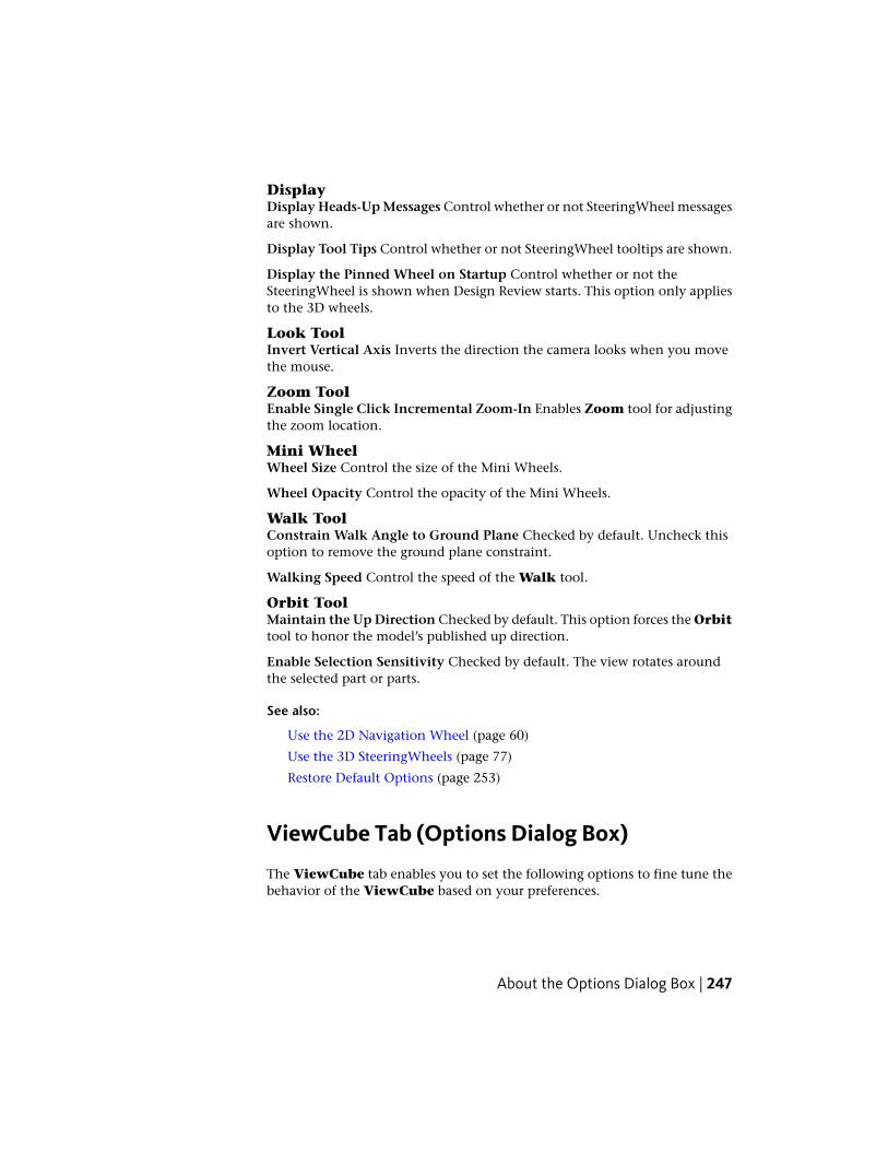
DisplayDisplay Heads-Up Messages Control whether or not SteeringWheel messagesare shown.
Display Tool Tips Control whether or not SteeringWheel tooltips are shown.
Display the Pinned Wheel on Startup Control whether or not theSteeringWheel is shown when Design Review starts. This option only appliesto the 3D wheels.
Look ToolInvert Vertical Axis Inverts the direction the camera looks when you movethe mouse.
Zoom ToolEnable Single Click Incremental Zoom-In Enables Zoom tool for adjustingthe zoom location.
Mini WheelWheel Size Control the size of the Mini Wheels.
Wheel Opacity Control the opacity of the Mini Wheels.
Walk ToolConstrain Walk Angle to Ground Plane Checked by default. Uncheck thisoption to remove the ground plane constraint.
Walking Speed Control the speed of the Walk tool.
Orbit ToolMaintain the Up Direction Checked by default. This option forces the Orbittool to honor the model’s published up direction.
Enable Selection Sensitivity Checked by default. The view rotates aroundthe selected part or parts.
See also:
Use the 2D Navigation Wheel (page 60)
Use the 3D SteeringWheels (page 77)
Restore Default Options (page 253)
ViewCube Tab (Options Dialog Box)
The ViewCube tab enables you to set the following options to fine tune thebehavior of the ViewCube based on your preferences.
About the Options Dialog Box | 247

Show the ViewCube Checked by default. Control whether or not theViewCube is shown.
Keep Scene Upright Checked by default. Uncheck this option to prevent themodel from switching to a top-up view, set by the designer, when a ViewCubeview is selected.
When Dragging on the ViewCubeSnap to Closest View Checked by default. Controls whether or not the viewsnaps to the closest available fixed view when you release the mouse buttonafter dragging the ViewCube.
When Clicking on the ViewCubeFit-to-View on View Change Checked by default. Zooms the view of themodel or selected object when you click the ViewCube.
When unchecked, clicking or dragging the ViewCube rotates around thecurrent center of rotation and does not zoom in or out.
Orient ViewCube to Current UCS Checked by default. The ViewCube isreoriented to the currently selected UCS, when one is active. When unchecked,or when no UCS is active, the ViewCube is oriented to the WCS.
When you create a UCS and make it active, a Coordinate System drop-downlist is displayed below the ViewCube. From the list, you can quickly select adifferent coordinate system or access the Manage Coordinate Systemsdialog box.
DisplayOn-Screen Position Position the ViewCube in any corner of the Canvas. Bydefault it is displayed in the Top Right corner.
NOTE When you change the position of the ViewCube, the position of the RollArrows and Home button are also changed relative to the ViewCube.
Size Set the display size of the ViewCube on the Canvas. The default settingis Normal.
Inactive Opacity Set the ViewCube visibility when the mouse pointer isdistant from the ViewCube. Move the mouse pointer near the ViewCubeto make it fully opaque (visible). The default inactive opacity is 50%.
See also:
Use the ViewCube (page 72)
About Coordinate Systems (page 196)
Restore Default Options (page 253)
248 | Chapter 4 Changing Design Review Options
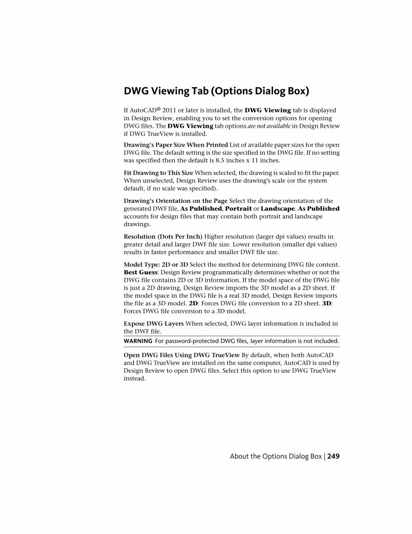
DWG Viewing Tab (Options Dialog Box)
If AutoCAD® 2011 or later is installed, the DWG Viewing tab is displayedin Design Review, enabling you to set the conversion options for openingDWG files. The DWG Viewing tab options are not available in Design Reviewif DWG TrueView is installed.
Drawing’s Paper Size When Printed List of available paper sizes for the openDWG file. The default setting is the size specified in the DWG file. If no settingwas specified then the default is 8.5 inches x 11 inches.
Fit Drawing to This Size When selected, the drawing is scaled to fit the paper.When unselected, Design Review uses the drawing’s scale (or the systemdefault, if no scale was specified).
Drawing’s Orientation on the Page Select the drawing orientation of thegenerated DWF file, As Published, Portrait or Landscape. As Publishedaccounts for design files that may contain both portrait and landscapedrawings.
Resolution (Dots Per Inch) Higher resolution (larger dpi values) results ingreater detail and larger DWF file size. Lower resolution (smaller dpi values)results in faster performance and smaller DWF file size.
Model Type: 2D or 3D Select the method for determining DWG file content.Best Guess: Design Review programmatically determines whether or not theDWG file contains 2D or 3D information. If the model space of the DWG fileis just a 2D drawing, Design Review imports the 3D model as a 2D sheet. Ifthe model space in the DWG file is a real 3D model, Design Review importsthe file as a 3D model. 2D: Forces DWG file conversion to a 2D sheet. 3D:Forces DWG file conversion to a 3D model.
Expose DWG Layers When selected, DWG layer information is included inthe DWF file.
WARNING For password-protected DWG files, layer information is not included.
Open DWG Files Using DWG TrueView By default, when both AutoCADand DWG TrueView are installed on the same computer, AutoCAD is used byDesign Review to open DWG files. Select this option to use DWG TrueViewinstead.
About the Options Dialog Box | 249

PDF Conversion Tab (Options Dialog Box)
The PDF Conversion tab enables you to set the conversion options whenopening a PDF file in Design Review.
Resolution (Dots Per Inch) Higher resolution (larger dpi values) results ingreater detail and larger DWF file size. Lower resolution (smaller dpi values)results in faster performance and smaller DWF file size.
Convert PDF Files to Black & White DWF Files When Saving Saves a PDFfile in black and white potentially reducing the resulting DWF file size.
See also:
About Saving an Open PDF as a DWF File (page 207)
Change Default Color OptionsDesign Review enables you to set the default colors of many things in theprogram.
Color-Related CommandsLocation
Canvas Color and markup status colors(For Review, Question, and Done)
General Tab (Options dialog box)
Paper Color, Dynamic Highlight Color,Sheet Hyperlink Color, and SelectionColor
Sheet Tab (Options dialog box)
Model Edge Color, Gradient Back-ground Color, Dynamic HighlightColor, and Selection Color
Model Tab (Options dialog box)
Additions and DeletionsCompareOptions dialog box
The way to change the colors is similar in each case.
250 | Chapter 4 Changing Design Review Options

Change Default Color Options
To apply a pre-defined color
1 If necessary, display the Options dialog box and tab of the desiredcolor-related command.
2 Click the command color button. The Color dialog box opens.
3 Under Basic Colors, click the swatch of the desired color.
4 To confirm the color change, click OK.
5 To apply the new pre-defined color, click OK.
To create a custom color
1 If necessary, display the Options dialog box and tab of the desiredcolor-related command.
2 Click the command color button. The Color dialog box opens.
3 Under Custom Colors, click Define Custom Colors. The Color dialogbox expands.
NOTE You can define a custom color by entering its specific Hue,Saturation, and Luminescence values or Red, Green, or Blue values inthe Color dialog box.
4 From the existing color swatches, select the standard color that is closestto the custom color you would like to create.
5 To get the exact color, drag the color selection icon and then the
saturation selection triangle. The custom color is shown in the Colorbox.
6 When satisfied with the custom color, click Add to Custom Colors.The custom color remains available in the Color dialog box for futureuse.
7 To confirm the color change, click OK.
8 To apply the new custom color, click OK.
Change Default Color Options | 251

Recover a DWF FilePower outages, system crashes, and other issues may abruptly close files beforeyou are able to save your changes. Enabled by default, Auto Recovery givesyou an opportunity to recover that work.
TIP You can control Auto Recovery settings, in the Options dialog box on theGeneral tab.
To recover a DWF file
1 Restart Design Review.
2 If a Customer Involvement Program dialog box opens promptingyou to describe the unexpected close, provide details and click OK.
3 A message box opens indicating that Auto Recovery is enabled andan open file was saved. Click OK.
4 Reopen the file that you were working on previously from its originallocation.
A dialog box opens indicating that a newer version of the file was savedautomatically.
5 Click the desired option.■ Click Use Newer Version to open the automatically saved version
from the backup files storage location.
■ Click Use Older Version to open the last version of the file yousaved from the original storage location.
■ Click Cancel to prevent either version of the file from being opened.The next time you try to open that file you will be prompted again.
See also:
General Tab (Options Dialog Box) (page 242)
Share Design Review OptionsSharing Design Review’s application options enables you to export all settingsavailable in the Options dialog box and application menu as an XML optionsfile. Once exported, you can place the options file in a central location ordistribute it by email. Team members and clients can then import the optionsfile ensuring that they have application settings identical to your own.
252 | Chapter 4 Changing Design Review Options
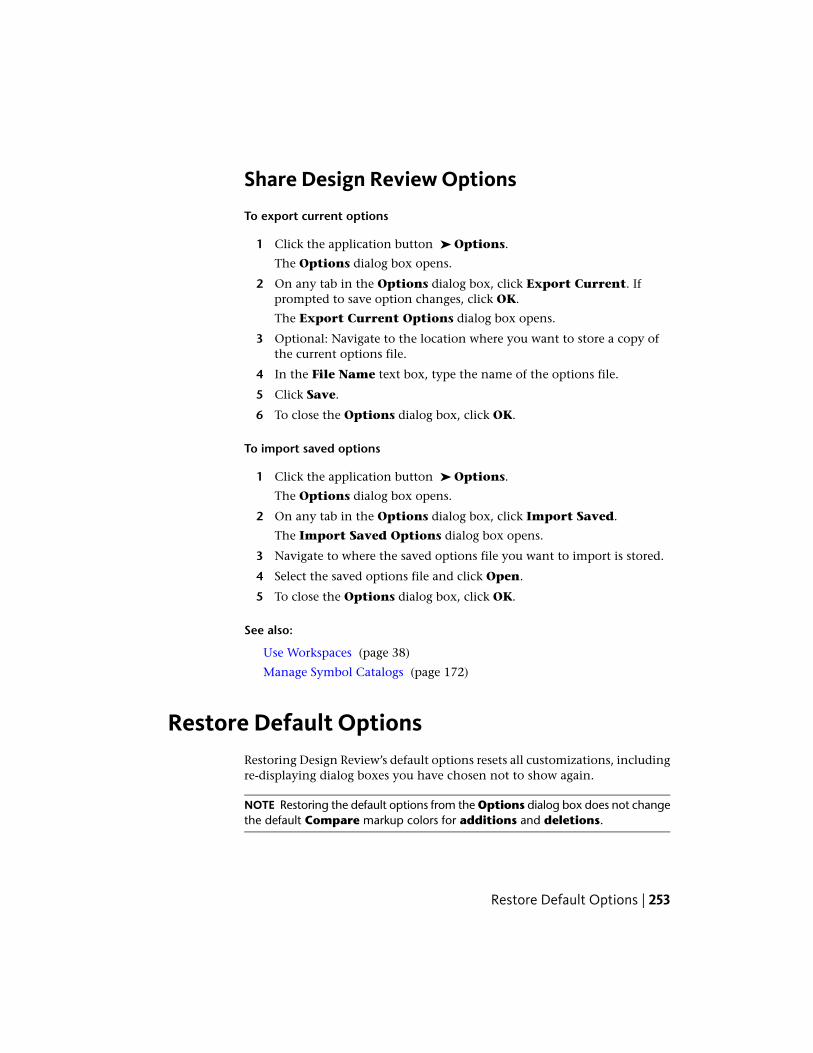
Share Design Review Options
To export current options
1 Click the application button ➤ Options.
The Options dialog box opens.
2 On any tab in the Options dialog box, click Export Current. Ifprompted to save option changes, click OK.
The Export Current Options dialog box opens.
3 Optional: Navigate to the location where you want to store a copy ofthe current options file.
4 In the File Name text box, type the name of the options file.
5 Click Save.
6 To close the Options dialog box, click OK.
To import saved options
1 Click the application button ➤ Options.
The Options dialog box opens.
2 On any tab in the Options dialog box, click Import Saved.
The Import Saved Options dialog box opens.
3 Navigate to where the saved options file you want to import is stored.
4 Select the saved options file and click Open.
5 To close the Options dialog box, click OK.
See also:
Use Workspaces (page 38)
Manage Symbol Catalogs (page 172)
Restore Default OptionsRestoring Design Review’s default options resets all customizations, includingre-displaying dialog boxes you have chosen not to show again.
NOTE Restoring the default options from the Options dialog box does not changethe default Compare markup colors for additions and deletions.
Restore Default Options | 253

Restore Default Options
To restore the original settings
1 Click the application button ➤ Options.
The Options dialog box opens.
2 On any tab in the Options dialog box, click Restore Defaults.
A dialog box opens, warning that any saved settings will be lost.
3 Click Yes to continue.
4 To close the Options dialog box, click OK.
Programming Options for Design ReviewDesign Review enables you to extend its functionality with an API (page 277).You can also customize your own applications to allow them to read and writeDWF files with the Toolkit.
Use APIs to Extend Design Review Functionality
The application programming interface (API) was originally created for theprevious viewing program, Autodesk DWF Viewer, so it emphasizes viewing,plotting, and user interface customization capabilities.
The API enables you to navigate to a specific page or view, set layer visibility,and control the user interface.
You must understand programming and ActiveX (page 277) technology in orderto use the API. You can program in these languages:■ Visual Basic® 6.0
■ Visual Basic® .NET
■ Visual C#®
■ Visual C++®
■ JavaScript
This API can be applied whether or not Design Review is standalone orembedded in other software. You can read more about the API and get samplecode at the Developer Center (http://www.autodesk.com/dwf-developers).
254 | Chapter 4 Changing Design Review Options

DWF Toolkit
Give your own applications the ability to read and write DWF files using theDWF Toolkit (http://www.autodesk.com/dwftoolkit).
See also:
Learning Resources (page 272)
Check for Design Review UpdatesDesign Review is updated regularly. When an update is available, you areprompted automatically to update the product. You have the option to bereminded later.
To check for updates manually
■ Click Home tab ➤ Assistance panel ➤ Help drop-down ➤ Checkfor Updates.
The Autodesk Design Review Information dialog box opens.
A message either indicates you already have the latest version installed, orthat new Autodesk Design Review product information is available.
To see which version you have installed
■ Click Home tab ➤ Assistance panel ➤ Help drop-down ➤ AboutAutodesk Design Review.
Disable Prompts for Automatic Updates
Based on your network policies, you may want to disable the automatic updateprompt shown when starting Design Review. You can still check for updatesmanually from the Help drop-down.
You only have the opportunity to disable update prompts when either a newversion or new information is available from Autodesk. If no new content isavailable when you Check for Updates, you will receive a message thatindicates that you have the latest version and no updates are available. TheDon’t Show This Again option will not be displayed.
Check for Design Review Updates | 255

To disable prompts for automatic updates
1 Click Home tab ➤ Assistance panel ➤ Help drop-down ➤ Checkfor Updates.
The Autodesk Design Review Information dialog box opens.
2 If a new version or new information is available from Autodesk, clickDon’t Show This Again.
256 | Chapter 4 Changing Design Review Options

Quick Reference Guide
Alternative Methods for Performing CommandsDesign Review often provides several ways to perform the same command:■ Application menu button, ribbon tabs, palettes, and toolbars
■ Keyboard shortcuts
■ Context menus
The application menu button, ribbon tabs, palettes, and toolbars are used mostoften to invoke a command. You can also use a keyboard shortcut (a key orcombination of keys you can press to perform a command quickly). Whenavailable, keyboard shortcuts are shown to the right of their respective toolnames in menus and tooltips.
NOTE Keyboard shortcuts are different than keytips. Keyboard shortcuts provide adirect way to perform a command immediately.
Another alternative to invoke a command is to use the context menu. In manylocations within Design Review, you can right-click to display commandsrelevant to the position of the mouse pointer. This right-click ability is especiallyimportant when viewing a DWF file in embedded mode, as menus and toolbarscan be hidden.
5
257

Application Menu
Keyboard ShortcutCommandIcon
Ctrl+NNew
Ctrl+OOpen/Open File
Ctrl+SSave
Ctrl+PPrint
Ctrl+ESend Email
Ctrl+WClose
Alt+F4Exit Design Review
258 | Chapter 5 Quick Reference Guide

Quick Access Toolbar
Keyboard ShortcutCommandIcon
Ctrl+OOpen
Ctrl+SSave
Ctrl+PPrint
Ctrl+ZUndo
Ctrl+YRedo
Ctrl+ESend Email
Alternative Methods for Performing Commands | 259
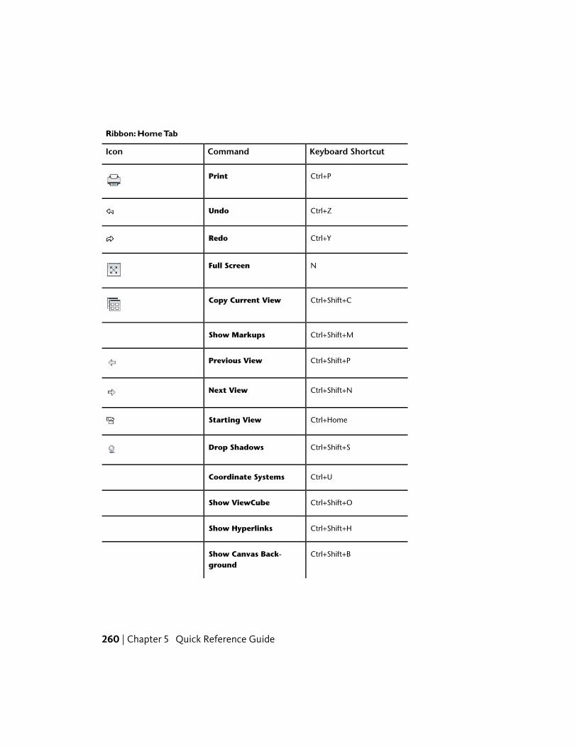
Ribbon: Home Tab
Keyboard ShortcutCommandIcon
Ctrl+PPrint
Ctrl+ZUndo
Ctrl+YRedo
NFull Screen
Ctrl+Shift+CCopy Current View
Ctrl+Shift+MShow Markups
Ctrl+Shift+PPrevious View
Ctrl+Shift+NNext View
Ctrl+HomeStarting View
Ctrl+Shift+SDrop Shadows
Ctrl+UCoordinate Systems
Ctrl+Shift+OShow ViewCube
Ctrl+Shift+HShow Hyperlinks
Ctrl+Shift+BShow Canvas Back-ground
260 | Chapter 5 Quick Reference Guide

Keyboard ShortcutCommandIcon
Ctrl+Shift+GSnap to Geometry
Ctrl+FFind Palette
F1Help
Alternative Methods for Performing Commands | 261

Ribbon: Markup & Measure Tab
Keyboard ShortcutCommandIcon
Ctrl+XCut
Ctrl+CCopy
Ctrl+VPaste
Ctrl+1Rectangle Callout
Ctrl+2Rectangle Callout withRectangle Cloud
Ctrl+3Rectangle Callout withPolycloud
Ctrl+4Circle Callout
Ctrl+5Circle Callout with Rect-angle Cloud
Ctrl+6Circle Callout with Poly-cloud
Ctrl+7Triangle Callout
Ctrl+8Triangle Callout withRectangle Cloud
Ctrl+9Triangle Callout withPolycloud
M or Spacebar(Enable last used callouttool)
262 | Chapter 5 Quick Reference Guide

Keyboard ShortcutCommandIcon
Shift+1Line
Shift+2Rectangle
Shift+3Freehand Highlighter
Shift+4Rectangle Cloud
Shift+5Polyline (Draw panel)
Shift+6Ellipse
Shift+7Rectangle Highlighter
Shift+8Polycloud
SFreehand
TText Box
GLength
UArea
IRelative Distance
WPolyline (Measure panel)
JLength/Radius
KAngle (2D and 3D)
Alternative Methods for Performing Commands | 263

Keyboard ShortcutCommandIcon
LPoint Location
OStamps
ZSymbols
SpacebarEnable last used markup toolfrom the Callouts, Draw,Measure, and Stamps &Symbols panels
264 | Chapter 5 Quick Reference Guide
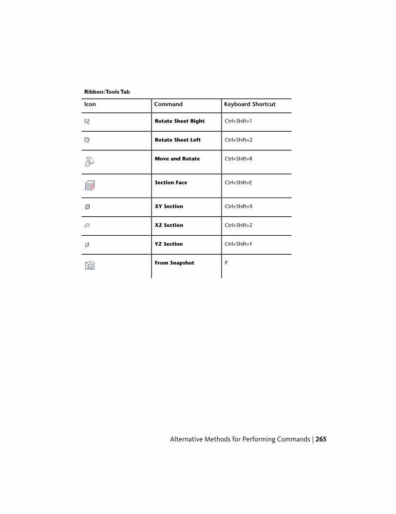
Ribbon:Tools Tab
Keyboard ShortcutCommandIcon
Ctrl+Shift+1Rotate Sheet Right
Ctrl+Shift+2Rotate Sheet Left
Ctrl+Shift+RMove and Rotate
Ctrl+Shift+ESection Face
Ctrl+Shift+XXY Section
Ctrl+Shift+ZXZ Section
Ctrl+Shift+YYZ Section
PFrom Snapshot
Alternative Methods for Performing Commands | 265

Ribbon:Animation Tab
Keyboard ShortcutCommandIcon
ZPlay
ZPause
WReverse
Ctrl+Shift+Right ArrowNext Interval
Ctrl+Shift+Left ArrowPrevious Interval
Ctrl+Right ArrowNext Sequence
Ctrl+Left ArrowPrevious Sequence
Ctrl+Shift+Plus/MinusSpeed
266 | Chapter 5 Quick Reference Guide

Canvas Toolbar
Keyboard ShortcutCommandIcon
ASelect
V to increase/Shift+V to de-crease
Field of View
HomeHome
HPan
Q (Dynamic Zoom) orCtrl+Plus/Minus keys (Con-trolled Zoom)
Zoom
FFit to Window
RZoom Rectangle
BOrbit
ETurntable
Ctrl+Shift+W2D Navigation Wheel
Ctrl+Shift+IView Object Wheel
Ctrl+Shift+JTour Building Wheel
Ctrl+Shift+KFull Navigation Wheel
Ctrl+Shift+.Mini View Object Wheel
Alternative Methods for Performing Commands | 267

Keyboard ShortcutCommandIcon
Ctrl+Shift+,Mini Tour BuildingWheel
Ctrl+Shift+/Mini Full NavigationWheel
PgUpPrevious Page
PgDnNext Page
268 | Chapter 5 Quick Reference Guide
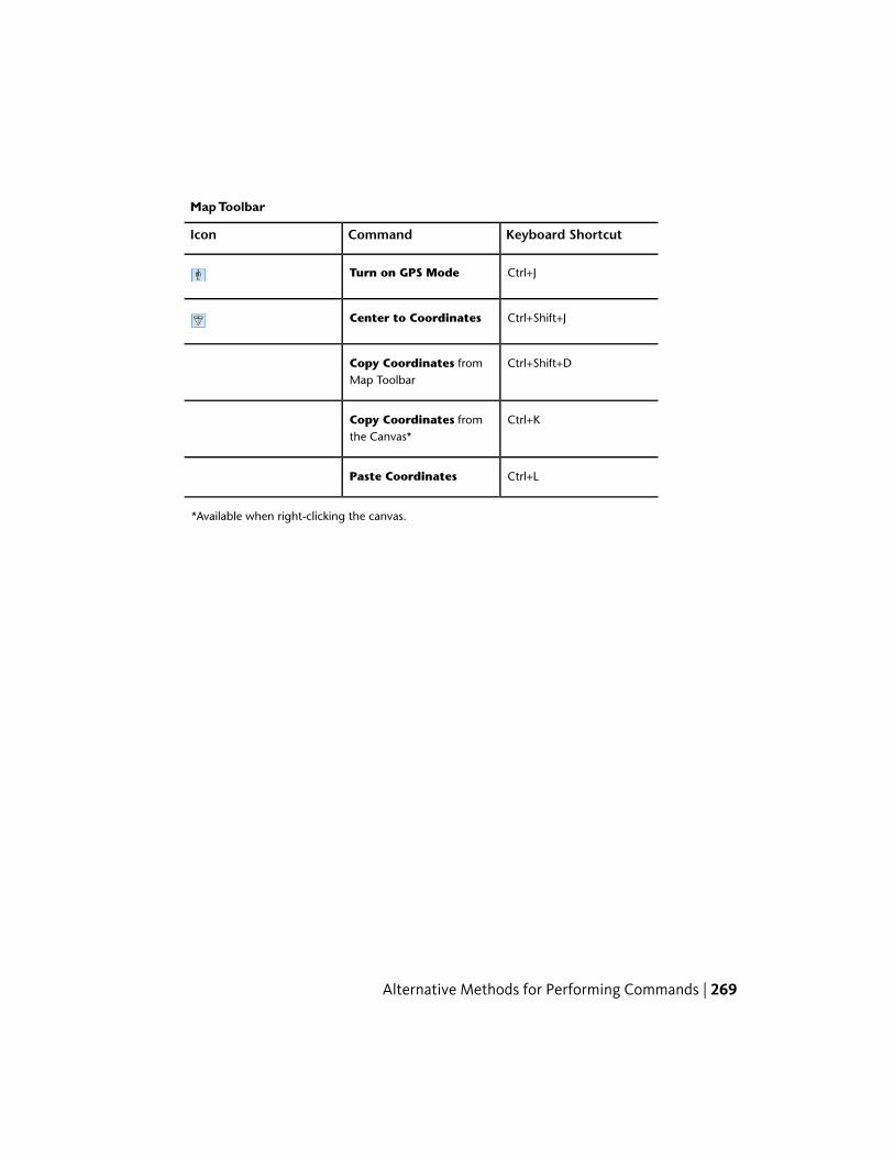
Map Toolbar
Keyboard ShortcutCommandIcon
Ctrl+JTurn on GPS Mode
Ctrl+Shift+JCenter to Coordinates
Ctrl+Shift+DCopy Coordinates fromMap Toolbar
Ctrl+KCopy Coordinates fromthe Canvas*
Ctrl+LPaste Coordinates
*Available when right-clicking the canvas.
Alternative Methods for Performing Commands | 269
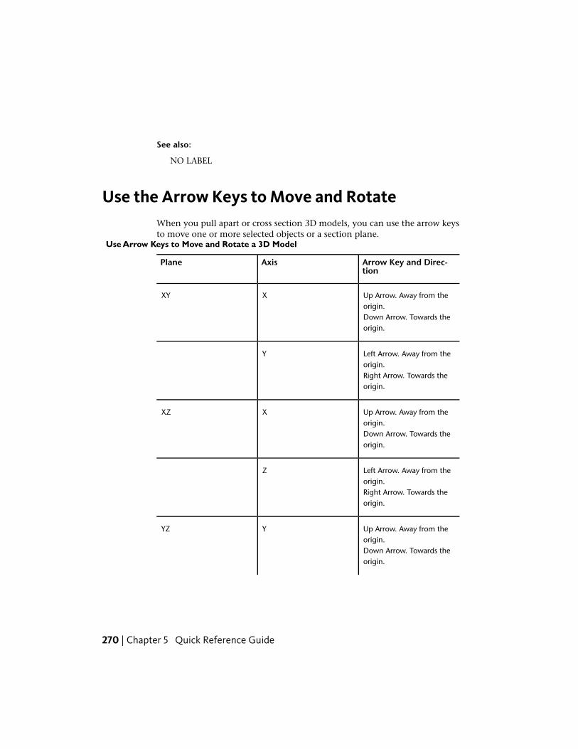
See also:
NO LABEL
Use the Arrow Keys to Move and RotateWhen you pull apart or cross section 3D models, you can use the arrow keysto move one or more selected objects or a section plane.
Use Arrow Keys to Move and Rotate a 3D Model
Arrow Key and Direc-tion
AxisPlane
Up Arrow. Away from theorigin.
XXY
Down Arrow. Towards theorigin.
Left Arrow. Away from theorigin.
Y
Right Arrow. Towards theorigin.
Up Arrow. Away from theorigin.
XXZ
Down Arrow. Towards theorigin.
Left Arrow. Away from theorigin.
Z
Right Arrow. Towards theorigin.
Up Arrow. Away from theorigin.
YYZ
Down Arrow. Towards theorigin.
270 | Chapter 5 Quick Reference Guide
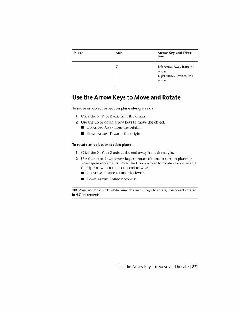
Arrow Key and Direc-tion
AxisPlane
Left Arrow. Away from theorigin.
Z
Right Arrow. Towards theorigin.
Use the Arrow Keys to Move and Rotate
To move an object or section plane along an axis
1 Click the X, Y, or Z axis near the origin.
2 Use the up or down arrow keys to move the object.■ Up Arrow. Away from the origin.
■ Down Arrow. Towards the origin.
To rotate an object or section plane
1 Click the X, Y, or Z axis at the end away from the origin.
2 Use the up or down arrow keys to rotate objects or section planes inone-degree increments. Press the Down Arrow to rotate clockwise andthe Up Arrow to rotate counterclockwise.■ Up Arrow. Rotate counterclockwise.
■ Down Arrow. Rotate clockwise.
TIP Press and hold Shift while using the arrow keys to rotate, the object rotatesin 45° increments.
Use the Arrow Keys to Move and Rotate | 271

See also:
Move and Rotate 3D Objects (page 95)
Move and Rotate Section Planes (page 102)
Learning ResourcesFor more information about Design Review, the DWF file format, andDWF-related products, explore these learning resources.
Design Review Support
■ Design Review Product Center: http://www.autodesk.com/designreview
■ Design Review Online Help: http://www.autodesk.com/designreview-help
■ Design Review videos on YouTube™: http://www.autodesk.com/designreview-youtube
■ Design Review Learning Path: http://www.autodesk.com/designreview-learn-ingpath
■ Design Review online demonstration: http://www.autodesk.com/designreview-tutorial
■ Design Review discussion group: http://www.autodesk.com/discussiongroup-designreview
■ Design Review Support Knowledge Base: http://www.autodesk.com/designre-view-support
■ Design Review API documentation: http://www.autodesk.com/dwf-developers
■ Design Review Updates & Service Packs: http://www.autodesk.com/designre-view-updates
■ Design Review Add-ins: http://www.autodesk.com/dwf-plugins
■ Autodesk® Freewheel Add-in: http://labs.autodesk.com/utilities/ShareNow/
Other DWF-Related Resources
■ Autodesk DWF Toolkit: http://www.autodesk.com/dwftoolkit
■ Beyond the Paper blog: http://www.autodesk.com/designreview-blog
■ DWF Developer Center: http://www.autodesk.com/dwf-developers
■ DWF discussion group: http://www.autodesk.com/discussiongroup-dwf
272 | Chapter 5 Quick Reference Guide

Other DWF-Related Autodesk Products
■ Autodesk® Buzzsaw®: https://access.autodesk360.com/
■ Autodesk® DWF™ Writer: http://www.autodesk.com/dwfwriter
■ Autodesk® Navisworks®: http://www.autodesk.com/navisworks
■ Autodesk® Seek: http://seek.autodesk.com
■ DWG TrueView™: http://www.autodesk.com/dwgtrueview
Non-Autodesk Websites
■ 3Dconnexion: http://www.3dconnexion.com
■ Autodesk User Group International: http://www.augi.com
■ HP Instant Printing® (HPIP): http://www.hp.com/go/hp-instant-printing/
■ Microsoft XPS Viewer: http://www.microsoft.com/whdc/xps/viewxps.mspx
Learning Resources | 273

274
Uninstall Design Review
Uninstall Design ReviewTo uninstall Design Review
1 Click Start ➤ Control Panel.
2 Click Add or Remove Programs.
NOTE For Windows 7, click Uninstall a Program.
3 From the list of programs, select Autodesk Design Review2013.
4 Click Change/Remove.
The Add or Remove Programs message box opens.
NOTE For Windows 7, click Uninstall/Change.
5 Follow the prompts to finish uninstalling the program.
NOTE After uninstalling Design Review, restart your computer.
Design Review does not uninstall customizations stored in your user profile incase you want to reinstall the product. To delete the customizations fromWindows XP, delete the \Documents and Settings\[user name]\Local
Settings\Application Data\Autodesk\Autodesk Design Review folder. FromWindows 7, delete the Users\[user name]\AppData\Local\Autodesk\Autodesk
Design Review folder.
6
275

276

Glossary
GlossaryActiveX A Microsoft® technology that allows programs to run within othersoftware. The software that holds the program, such as Internet Explorer® orMicrosoft® Word, is called the container. The program that runs inside it, suchas Design Review, is called the control.
API Application Programming Interface. A programming language used toenable applications to communicate with each other.
application button The button that is displayed in the top-left corner of theapplication. If you click the application button, the application menu isdisplayed.
application menu The menu that is displayed when you click the applicationbutton. The application menu contains common tools for creating, saving, andpublishing a file.
assembly An object in a 3D model. An assembly can be made up of smallerobjects called subassemblies or subobjects.
block A meaningful set of geometric shapes. Also known as an object orassembly.
BOM Bill Of Materials. A hierarchical list, like a parts list. A BOM describes aproduct in terms of its component parts.
BPJ Batch Print Job. A file that stores saved batch print settings for severalDWF files.
CAD Computer Aided Design. The process of using a computer program todesign drawings and models of physical objects.
7
277
canvas The primary viewing and markup area for a sheet or model.
cap A cap is the flat surface displayed after using the Cross Section tool.Disabling caps allows you to see parts as if they are hollow.
command prompt In a command-line interface, the command prompt is anindicator that shows the computer is ready to receive a command.
coordinate system A coordinate system is a method used to indicate theposition of 3D content in dimensional space.
cross section A section made by cutting a model at an angle, usually to displayan interior view.
datum A mapped reference point from which GPS measurements can be made.Each datum includes both an ellipsoid, which specifies the size and shape ofthe earth, and a base point for latitude and longitude. If two maps use differentdatums, points on the map may not line up.
digital signature A method used to maintain file authenticity and to providea safe environment for sending and receiving data.
Direct3D A method used to improve rendering 3D graphics.
dpi Dots Per Inch. A method of measuring image or text resolution.
DWF
An open, published, and secure file format developed by Autodesk, DWFenables you to combine and publish rich 2D- and 3D-design data and shareit with others.
DWFx
A version of DWF based on the XML Paper Specification (XPS) from Microsoft.DWFx enables DWF files to be viewed using the free Microsoft XPS Viewer.Generically referred to as DWF.
DWG DWG refers to the file extension (.dwg) of an AutoCAD file.
DXF Drawing EXchange Format. A file format that enables the exchange ofdrawings between AutoCAD and other programs. DXF is a predecessor of DWF.Also known as “Drawing Interchange Format.”
expanded panel
An area on the ribbon associated with a ribbon panel. An expanded panelcontains additional tools and controls. See also ribbon panel and ribbon.
278 | Chapter 7 Glossary
FEA Finite Element Analysis. A way to use colors to identify stresses,displacements, heat transfer, fluid dynamics, or electromagnetism inmechanical objects as defined by the DWF file publisher.
field of view The area that can be seen when looking through a device froma specific location, or vantage point. By decreasing or increasing the angle ofview, you can narrow or widen the field of view, thereby controlling howmuch can be seen through the device.
FTP File Transfer Protocol. A method of moving files (larger than 10 megabytes)from one location to another over the Internet.
georeferenced map A 2D sheet within a DWF file published by Autodesk®
Map 3D 2008 or later that contains a global coordinate system and definedlatitude and longitude coordinates based on the WGS84 datum.
GPS Global Positioning System. A satellite navigation system that can locatethe latitude and longitude of a GPS device on Earth.
gradient A color fill or pattern that uses a smooth transition between darkershades and lighter tints of one or two colors.
grip A small circle that displays when you select a markup object. Each objecthas several grips. Grips are used to resize the markup. All markups have gripsexcept for freehand shapes.
History A section in the Markup Properties palette, History shows noteand status changes saved in all markups.
hyperlink A way to associate graphical objects with related documents, suchas other drawings, bills of materials, or project schedules.
intranet A company-specific network used to share information betweenco-workers.
iPart A part with variations that have been published and are embedded in aDWF file.
layer Published by the author of a DWF file, a layer is a way to group similarinformation in a drawing by function and to enforce line type, color, andother standards. Layers are the primary organizational tool used in drawing.Layers are the equivalent of the overlays used in paper-based drafting.
MAPI Messaging Application Programming Interface. The Microsoft®
Windows® messaging system that allows various email applications to sendand receive email.
Glossary | 279

model A meaningful collection of 3D objects. Also a generic way to refer to3D content.
My Views A list of views created and saved in Design Review. My Views isshown in the Views palette.
named view A view created and named in Autodesk products. Each namedview is shown in the Views palette.
NMEA 0183 An electrical and data transmission standard used by GPS devicesdefined by the National Marine Electronics Association.
Notes A section in the Markup Properties palette that can be used to adda note to a markup.
object Generically, any item on the canvas, Markups palette, or Modelpalette. Objects created in Design Review are called markup objects. Objectscreated in the DWF publishing program are called published objects. An objectin a 3D model is sometimes called an assembly or part.
OpenGL A method used to improve rendering of 2D and 3D graphics.
orthographic view A view of a 3D model in which all lines on each axis areparallel to each other.
palette A group of related tools that enable you to find and display sheets,their markups, layers, views, and properties.
PDF Portable Document Format. A file format created by Adobe used totransmit and display documents regardless of the software of the sender orreceiver. It includes fonts, formatting, and graphics.
perspective view In order to give the illusion of depth, a view of a 3D modelwhere parallel lines appear to converge toward a vanishing point.
point A unit of measure used to determine text height or line width. Onepoint equals 1/72nd of an inch.
properties Attributes of a sheet, markup, or object displayed in the applicableProperties palette. These properties may include the author name, time ofcreation, and, for markups, their Status and Notes.
push pin A push pin-shaped button used on the ribbon and in the applicationmenu. On the ribbon, push pins are used to keep a ribbon panel expanded.In the application menu, push pins keep an item in the list of recently openeditems.
raster image A type of graphic file, such as a BMP file, made up of individualpixels.
280 | Chapter 7 Glossary

resolution The degree of sharpness with which an image is displayed. Imagesare composed of points called pixels. The greater the number of pixels, thebetter the resolution. Too many pixels can create large files, which may transferslowly over the Internet and may perform sluggishly when viewed.
ribbon The horizontal area of the application window that contains task-basedtabs and panels with tools for viewing, marking up, and sharing DWF files.
ribbon panel
A set of labeled controls, related to a task, grouped together in a ribbon.Multiple ribbon panels, belonging to one workflow, are grouped togetherunder a ribbon tab.
ribbon tab
Highest level of ribbon grouping, based on an action. A ribbon tab containsgroups of multiple ribbon panels, each belonging to one workflow. A ribbonpanel contains buttons and controls, related to a task.
snap A point on an object that acts like a magnet, allowing you to attach oneobject to another at a precise point.
status A way to indicate the current condition of a markup or sheet. Markupstatus is indicated in the Markup Properties palette. Each sheet may havecustom stamps applied to indicate its status.
toolbar A row of icons that represent related tools. Each icon, when clicked,invokes an action.
tracking menu A cluster of graphical buttons, called wedges, which followsthe mouse pointer as you move it around the canvas, tracking it.
trails Lines in a DWF file animation that show the relationship of a componentto the assembly. In an animation, trails indicate the distance and the pathalong which a component was moved to create the view.
twip TWentIeth of a Point. A unit of measure, a twip equals 1/1440th of aninch.
UCS User Coordinate System. A user-defined coordinate system enables youto set up a point of reference for a particular set of point locationmeasurements.
UNC Universal Naming Convention. A standard for identifying servers,printers, and other resources in a network. A UNC path uses double slashesto represent the drive and directories in which the server can be found. Thedisk and directories are separated with a single slash or backslash, as follows:
Glossary | 281
Unix: //servername/path
DOS and Windows: \\servername\path
vector image A type of graphic file made up of individual objects, such aslines and shapes. Vector images retain a high quality at any scale.
viewport A window area on a layout sheet that reveals various views of thesame drawing.
WCS World Coordinate System. A coordinate system used as the basis fordefining all objects and other coordinate systems. In Design Review, Y is up.In AutoCAD and Inventor, Z is up.
wedge A clickable button on a wheel.
workspace A set of various views of a drawing combined onto a sheet,originally for printing. In AutoCAD products, each layout sheet (sometimesreferred to as “paper space” or paper mode) has a defined paper size,orientation, and other page settings.
282 | Chapter 7 Glossary

Index
2Dannotations 158callouts 158drawing tools 162, 163markup 158measurements 180sheets 24, 25
3Danimated views 244annotations 176callouts 176field of view 66invert selection 17lighting 91markup 176measure 194measurements 191models 63move object 95orbit 69pull-apart 95reset object 99reset section plane 108rotate object 95shading 93shadows 94sheets 24, 25view cross section 100views 64
A
accelerator keys 10accessibility 10accuracy 181activate
coordinate system 199ActiveX 254add leaders 160add sheets 134
Add-ins 132DGN 132Freewheel 132JT 132
Adobe PDF 46aggregate DWF files 133, 134angle 186, 191, 194, 202angle of view 66animated views 244animation 109
assembly instructions 118camera 117controls 110enable 112find 112load 112loop 117markup 115play 110, 112playback speed 117select 110, 112smooth 244speed 117trails 118views 113
Animation tab 110annotations 158, 176API 254application button 11application menu 11application program interface 254area 185, 186, 188arrow style 165assemble an object 118assemblies 63assembly instructions 118attach
digital signatures 211author of markup 27, 29Auto Recovery 252Autodesk Seek 54
283 | Index

B
background color 59batch print 222
command prompt 225save settings 222start 224
Bill of Materials 119black and white 57
convert PDFs 250BOM 119
print 123view 121
bookmarks 31BPJ 222Buzzsaw 43, 52, 208, 225
open from 52save to 208
C
callouts 140, 1622D 1582D markup callout tools 1583D 1763D markup callout tools 176create 2D 159create 3D 176edit text 151format 148
camera target point 70canvas
copy 230Canvas toolbar 17caps 107
cross sections 107hide 107show 107
capture 137catalog
delete 172export 172import 172manage 172rename 172symbols 167, 168, 169, 172
certificate 210authority 210root 210trust hierarchy 210
certificatesabout 210
changes 231Check for Updates 255
disable 255circle 140, 162, 163clear all markup 142close 50cloud 140, 162, 163color
Additions 250Background Color 250custom 251Deletions 250Dynamic Highlight Color 250Gradient Background Color 250markup status 250Model Edge Color 250Paper Color 250pre-defined 251Selection Color 250Sheet Hyperlink Color 250
color options 250combine DWF files 133, 134command prompt
batch print 225print to file 219
comment 140, 162compare 231
options 233compare 2D content 233compatibility 43composite DWF files 133contents
List View palette 25Thumbnails palette 24
context menu 12context menus 257convert PDF to black and white 250coordinate system 196
activate 199add 197
284 | Index

copy 200manage 199tripod 201user coordinate system 196world coordinate system 196
copycanvas 230coordinate system 200current view 230image 230markup 152properties 230sheets 134
create 130create a DWF file 228create sheets 137cross sections 100
caps 107delete 108flip 104rename 108reset 108undelete 109viewpoint 107
Cross Sections palette 34, 100CSV 155current view
copy 230custom color 251custom layouts 38custom symbols 29, 140, 167, 172custom workspace 38customize user interface 38cut
markup 152
D
default file format 243defaults 253delete
all saved views 33leader 160markup 152saved view 33sheets 139
user coordinate system 201design review process 2DGN 132differences 231, 233digital design workflow 2digital signatures 210
attach 211digital rights management 210DRM 210DWFx 211invalid 211, 213root certificates 210signed file information 213valid 213view details 213
digitized signatures 210dimensions 27, 29, 140disable
animation camera 117Check for Updates 255
disabled DWF files 44discussion group 272distance 191, 194, 202distribute 225drag and drop to PowerPoint 235drag and drop to Word 235draw 163drawing tools 162, 163drop shadows 94DWF
georeferenced 124new file 134open 50save 206
DWF Composer 254DWF files (Design Web Format)
about 1DWF format 206DWF Toolkit 255DWF Writer 130
publish 131DWFx
digital signatures 211open 50save 206
Index | 285
DWFx filesabout 1
DWG 45open 50resolution 249
DWG Viewing options 249DXF 45
open 50
E
edges 93edit
callout text 151text in stamps 151
ellipse 140, 162, 163email 43, 225, 228
DWF file 226DWF files from Windows
Explorer 227embed 43, 225
DWF file and viewer 235limitations 235PowerPoint 235Word 235
exit 50export current options 252
F
FAQ 272feedback 140, 162field of view 66file
digitally signed 211preview 13recent 12save 206save to
Buzzsaw 208save to Buzzsaw 208sort 12
File Settings 206file transfer protocol 43, 225file types
supported 45
filespinned 12
find 29animation 112hidden text 53text 53wildcards 53
Find palette 37Fit to Window 57flat table 120flip 104font size 149format
markup 148measurements 148
FOV 66freehand 140, 162, 163freehand highlighter 140, 162, 163Freewheel 132, 209FTP 43, 225full-screen mode 16
G
general options 241General Tab
Auto Recovery 242Automatic Palette Launching 241File Notifications 242File Settings 243Markup Settings 242View Settings 241Zoom Tool 242
georeferenced map 124GPS 124
configure device 128NMEA 0183 124
GPS options 245GPS Tab
Connection 245Status 246
grayscale 57Grid Data palette 37Grid Data toolbar 18grid table 120
286 | Index

H
H grid table 120Help 4
Contents 4Favorites 4Index 4Search 4
hide3D objects 90background 59caps 107cross section 106Cross Sections palette 34Find palette 37Grid Data palette 37Layers palette 35List View palette 26Markup Properties palette 27markups 142Markups palette 29Model palette 31Object Properties palette 28section plane 105, 106Sheet Properties palette 26Text Data palette 36Thumbnails palette 24Views palette 32
highlighterfreehand 140, 162, 163rectangle 140, 162, 163
Home 57HP Instant Printing 220HPIP 220hyperlink 55
find 55follow 55, 56, 244multiple links 55viewport 55
I
imagecopy 230
images 47, 48open 47
raster 62resolution 48rotate 62symbols 167
importDGN 132DWF as a symbol catalog 169JT 132symbols 169
import saved options 252instructions for assembly 118isolate 3D objects 17, 90
J
JavaScript 254join DWF files 134JT 132
K
keyboard shortcuts 257keytips 10
L
label 27Large Thumbnails 24layers 35Layers palette 35leader
add 160remove 160
leader line 140length 185, 186, 191, 194, 202lighting 91line 140, 162, 163
end style 165pattern 165start style 165thickness 151weight 151width 151
List View 25load animation 112
Index | 287

load time 50lock markups 143loop
disable 117enable 117
loop animation 117
M
map 124center 127Center to Coordinates 125Copy Coordinates 125current location 127datum 124Display Mode 125Enter Coordinates 125georeferenced 124GPS Mode 125Lat 125latitude 124Long 125longitude 124Map Menu 125Paste Coordinates 125Units and Systems 125view coordinates 127Zoom Ratio 125
Map toolbar 19Map Toolbar 125MAPI 226markup 29, 140, 142, 162, 163
2D annotations 1582D callout tools 1582D callouts 1583D annotations 1763D callout tools 1763D callouts 176Additions 233animations 115copy 152created 142creator 142cut 152delete 152Deletions 233
disabled 141drawing tools 162, 163format 148formatting tools 147history 142label 142, 154line weight 151lock 143modfied 142move 146notes 142, 154paste 152properties 142resize 146rotate 175save summary 155secure 143select 145shapes 163sheet 142snaps 156stamps 166, 167status 154tabular data 123unlock 143view 29
Markup Properties palette 27markup status 29
Done 29For Review 29None 29Question 29
markup types 140, 163markup-disabled DWF files 141Markups palette 29, 140, 162, 163measure
3D 194angle
2D 1893D 205
area 188create 2D 186create 3D 202diameter 204disabled 178Display Precision for 2D 181
288 | Index

Display Precision for 3D 192, 193Display Units for 3D 192, 193distance 202Drawing Units for 2D 181Imperial 181, 192length 186, 204metric 181, 192point location 203polyline 188precision for 2D 181precision for 3D 193radius 204relative distance 204scale 181Units and Scale 181units for 2D 181units for 3D 192
Measure Tools 1772D objects 1853D objects 194angle 202Angle 191, 194
2D 1893D 205
Area 185, 188Length 185, 186, 191, 194, 202Length/Radius 191, 194, 202, 204Point Location 191, 194, 202, 203Polyline 185, 188Relative Distance 191, 194, 202, 204
measure-disabled DWF files 178measurements
2D 1802D accuracy 1813D 191format 148Markups palette 177snap 2D 185
menusapplication 11context 12right-click 12
merge DWF files 134Microsoft PowerPoint 235Microsoft Word 235Microsoft XPS Viewer 1
model options 244Model palette 30Model Tab
Color Settings 244Object Highlighting 245Shadow Settings 245View Settings 244
move3D object 95object within a plane 271section plane 102
multiple cross sections 100My Views 32
create 32delete a saved view 33delete all saved views 33rename 33update 33
N
newDWF file 134
new features 3next view 59
O
Object Properties palette 28objects 63, 95online search 55open
Adobe PDF 50DWF 50DWF file from Buzzsaw 52DWFx 50DWG 45, 50DXF 45, 50images 47multiple DWF files 49PDF 46recovered DWF files 252
options 241Big SteeringWheel size 246clicking the ViewCube 248color 250
Index | 289

Color Scheme 241dragging the ViewCube 248DWG Viewing 249Export Current 252file format 243General Tab 241GPS connection 245GPS connection status 246GPS Tab 245hyperlink settings 244Import Saved 252Look 247markups 242Mini SteeringWheel size 247model color settings 244model object highlighting 245Model Tab 244model view settings 244notificiations 242object highlighting 243Orbit 247palettes 241paper settings 243PDF Conversion 250printing 214programming 254recovery 242Restore Defaults 253shadow settings 245sheet size settings 243Sheet Tab 243SteeringWheel display 247SteeringWheels 246view 241ViewCube 247ViewCube display 248Walk 247zoom 242Zoom 247
Orbit 69
P
palettes 19, 21control automatic display 241Cross Sections 19, 34, 100
Find 19, 37Grid Data 19, 37Layers 19, 35List View 19, 25Markup Properties 19, 27Markups 19, 29, 140, 162, 163Model 19, 30Object Properties 19, 28resize a column 23save workspace 38Sheet Properties 19, 26sort a column 24Text Data 19, 36Thumbnails 19, 24Views 19, 31
pan 57, 60panels 14
contextual 14hide 14show 14
pasteimages 152markup 152properties 230
PDF 46convert to black and white 250open 46, 50resolution 250
PDF Conversion options 250Perspective view 64picture 137pinned files 12Pivot 69play animations 110, 112point location 191, 194, 202points 191, 194, 202polycloud 140, 162, 163polygon 140, 162, 163polyline 140, 162, 185, 186
draw 163measure 188
PowerPoint 235slide show 237
pre-defined color 251precision 181preview 217
290 | Index

previous view 59print 217
batch print 222disabled 214drawing alignment 216DWF files from Windows
Explorer 221instant printing 220options 214preview 217Quick Print 217selected sheet 217several DWF files 222tabular data 123to file 219
print preview 217print-disabled DWF files 214PRN 219programming 254programs that can open DWF files 226
AutoCAD 226Buzzsaw 226Inventor 226Productstream 226Revit 226Streamline 226Vault 226
progress bar 50progressive tooltips 11properties
copy 230markup 142markups 27object 28paste 230select 230sheets 26
property types 27publish 130, 131
DWF Writer 131Windows Explorer 131
publish DWF 228pull-apart 95
Q
Quick Access toolbar 13Quick Print 217
R
radius 191, 194, 202rearrange sheets 136receive DWF files 43recent documents 11, 12recover files 252rectangle 140, 162, 163rectangle cloud 140, 162, 163rectangle highlighter 140, 162, 163redline 140, 162Redo 13relative distance 191, 194, 202remove
catalog 172remove leaders 160remove program 275rename
cross sections 108My Views 33sheets 138user coordinate system 200views 33
reorder sheets 136reset
3D object 99cross section 108section plane 108view 61
resize a palette column 23resize palette 19resolution 181
DWG 249PDF 250
restore default options 253review 140, 162revise 140, 162revision clouds 29, 140, 162, 163ribbon 14
panels 14tabs 14
Index | 291

right-click menu 11root certificate 210rotate 71
3D model 693D object 953D views 69horizontally 69, 71images 62markup 175parallel 69section plane 102sheets 62target point 70vertically 69, 71
roundtripping 2
S
sample DWF files 272save 206
Auto Recovery 252Buzzsaw 208DWF 206DWFx 206Freewheel 209markups summary 155My Views 32PDF as DWF 207print settings 219, 222view 32
save asDWF 243DWFx 243Save to Buzzsaw 208Save to Freewheel 209
scale 181screen capture 137search
Help 4online 55text 53
section plane 100, 102, 105move 102rotate 102
secure markups 143seek 55
Seek utility 54select 17
2D objects 173D objects 17invert 17properties 230
Select Animation 110, 112select objects 63Select tool 17selection 17
symbol catalog 168send 225, 226, 227, 228shade 3D Objects 93
Edges Only 93Shaded 93Shaded with Edges 93
shadows 94shapes 27, 29, 140, 162, 163
draw 163markup 163
share DWF files 225, 226, 227, 228shared network folder 43, 225ShareNow 132sheet options 243Sheet Properties palette 26Sheet Tab
Hyperlink Settings 244Object Highlighting 243Paper Settings 243Sheet Size Settings 243
sheets 24, 25copy 134create 137delete 24, 25, 139hide layers 35navigate 17print 24, 25rename 24, 25, 138reorder 136rotate 62show layers 36turn layers off 35turn layers on 36
shortcutscontext menus 257keyboard 257
292 | Index
show3D objects 90background 59caps 107cross section 106Cross Sections palette 34dialog boxes 253Find palette 37Grid Data palette 37Layers palette 35List View palette 26Markup Properties palette 27markups 142Markups palette 29Model palette 31Object Properties palette 28section plane 105, 106Sheet Properties palette 26Text Data palette 36Thumbnails palette 24Views palette 32
signatures 210Small Thumbnails 24smooth animations 244smooth camera transitions 244smooth transitions 244snap 185snap points 156Snap to Geometry 156snaps 156snapshots 137
create sheets 137symbols 167
sort column 24spin 71square 140, 162, 163stamps 140, 166
edit text 151Standard Views 64
Back 64Bottom 64Front 64Front Bottom Left 64Front Bottom Right 64Front Top Left 64Front Top Right 64
Left 64Right 64Top 64
status 29markup 29
SteeringWheel2D Navigation Wheel 60Full Navigation Wheel 77, 86Pivot 81, 86Tour Building Wheel 77, 83View Object Wheel 77, 81wedge 60, 77
SteeringWheel options 246SteeringWheels Tab
Big Wheel 246Display 247Look 247Mini Wheel 247Orbit 247Walk 247Zoom 247
subobjects 63summary 155support knowledge base 272symbol catalog 167, 168, 169, 172
delete 172export 172import 172manage 172rename 172selection 168
symbols 140, 167custom 168, 169, 172from selection 168import a DWF file 169place 171
T
tablemarkup 123view 121
tabs 14Animation tab 110contextual 14hide 14
Index | 293
show 14tabular data 119
markup 123print 123view 121
target point 70text
find 53text box 140, 162, 163Text Data palette 36thumbnails 24TIFF 62toolbars
Canvas 17contextual 18Grid Data 18Map 19Quick Access 13save workspace 38show more buttons 17
toolkit 255tooltips 11, 257track markup 142track measurements 177tracking menu 60, 77trails
disable 118enable 118
transitions 244transparent 90tripod
coordinate system 201hide coordinate system 201show coordinate system 201
troubleshooting 272missing tools 235opening DWG files 46printing 216
turntable 71
U
UCS 196Undo 13uninstall 275unlock markups 143
unprintable 214update 255update a saved view 33user coordinate system 196
delete 201rename 200
V
validatedigital signatures 213files 213
validatingcertificate 210
VB Script 254VCR controls 110view
3D cross section 1003D models 64animations 113BOM 121canvas background 59markup 29next 59previous 59rename 33reset 61save 32tabular data 121thumbnails 24
ViewCube 72ViewCube options 247viewpoint 107viewport 179views 31
Standard Views 64Views palette 31visibility 90Visual Basic 254Visual C# 254Visual C++ 254
W
WCS 95, 196web page 55
294 | Index
wedge 60, 77Windows Explorer
email DWF files 227print DWF files 221publish 131Publish DWF and Email 228
Word 235workflows
digital design 2
workspace 38world coordinate system 196
Z
zoom 57, 60, 70Zoom Extents 57Zoom Rectangle 57
Index | 295

296