
AUTO START MODULE WITH VOLTAGE SMART-TURBO
28
OFFICE: BOUTROS BLDG., 1ST BSMT, CHEIKH‐GHABI, BEIRUT 2068 7808 TEL: 961‐1‐216994 (2 LINES), FAX: 961‐1‐339600 HEADQUARTERS AND FACTORY: S. & A. S. BLDG, SEASIDE ROAD, JIEH CHOUF TEL: 961‐7‐996333 (2 LINES), FAX: 961‐7‐996116 TECHNICAL SUPPORT: 961‐71‐996333 E-MAIL: [email protected] W W W . S A S C O N T R O L L E R S . C O M USER’S MANUAL FOR S/W V.300.1 ONWARDS 2131 AUTO START MODULE WITH VOLTAGE AND FREQUENCY DISPLAY SMART-TURBO
Transcript of AUTO START MODULE WITH VOLTAGE SMART-TURBO

OFFICE: BOUTROS BLDG., 1ST BSMT, CHEIKH‐GHABI, BEIRUT 2068 7808 T E L : 9 6 1 ‐ 1 ‐ 2 1 6 9 9 4 ( 2 L I N E S ) , F A X : 9 6 1 ‐ 1 ‐ 3 3 9 6 0 0HEADQUARTERS AND FACTORY: S. & A. S. BLDG, SEASIDE ROAD, JIEH CHOUF T E L : 9 6 1 ‐ 7 ‐ 9 9 6 3 3 3 ( 2 L I N E S ) , F A X : 9 6 1 ‐ 7 ‐ 9 9 6 1 1 6TECHNICAL SUPPORT: 961‐71‐996333 E-MAIL: [email protected] W W . S A S C O N T R O L L E R S . C O M
USER’S MANUALFOR S/W V.300.1 ONWARDS 2131
AUTO START MODULE WITH VOLTAGE AND FREQUENCY DISPLAY
SMART-TURBO


1. OVERVIEW
2.DISPLAY
FUNCTIONS
4. ACCESSING
THE MENU
5. TECHNICAL
SPECIFICATION
1.1 FEATURES 1.2 DESCRIPTION 1.3 OPERATION
2.1 DISPLAYED PAGES
3.1 FRONT PANEL LEDS 3.2 DETECTED AND SIGNALED FAULTS AND WARNINGS
3.2.1 WARNINGS 3.2.2 FAULTS
3.3 DESCRIPTION OF STATUS MESSAGES SHOWN ON DISPLAY
4.1 MENU DESCRPTION
5.1 SPECIFICATION 5.2 ABSOLUTE MAXIMUM RATINGS
3. FRONT
PANEL
DESCRIPTION
6.1 FIRMWARE UPGRADE USING PC 6.1.1 INSTALLING THESAS DEVICE USB DRIVER 6.1.2 NSTALLING THE FIRMWARE UPGRADE SOFTWARE 6.1.3 FIRMWARE UPGRADE PROCESS
6.2 FIRMWARE UPGRADE USING GOOGLE PLAY STORE ON SMART PHONE
6.2.1 INSTALLING THE SASPTOOL FIRMWARE APPLICATION ON THE MOBILE
6.2.2. FIRMWARE UPGRADE PROCESS
6. FIRMWARE
UPGRADE
7.APPENDI
X A 7. APPENDIX A


1. OVERVIEW 1.1 FEATURES
Microcontroller based design Operation by 3 push buttons Easy to fit DIN standard 72x72 panel mount housing Connection is via locking plug and socket connectors Solid-state short circuit protected outputs Simultaneous display of AC voltage, frequency, hour counter, battery voltage and the number of hours since the last oil change
Parameters can be edited and updated at any time even when engine is running Menu accessible from front panel Oil change notification alert Front panel Leds for status and alarm indication Automatic engine starting and stopping Automatic shutdown on fault condition Low oil pressure alarm and shut down High engine temperature alarm and shut down Dynamo failure alarm and shut down Low fuel alarm and shut down Over/Under speed alarm and shut down
Over/Under voltage alarm and shut down Over/Under battery voltage alarm and shut down Coolant level alarm and shut down General alarm output
1.2 DESCRIPTION Smart-TURBO is a new addition to the Smart series. It is an intelligent auto start and protection module with frequency display, AC voltage, battery voltage, run hour counter and run hours since the last oil change. Automatic assembly and microcontroller based high integration design resulted in this low-cost yet high performance controller.
1.3 OPERATION
Three modes of operation are provided. Following is a description of each mode: Stop Mode: In this mode, the engine is shut down along with the module. All faults and alarms are reset. Auto Mode: In this mode, the genset is ready to start. Starting is controlled by the remote control input. Following is a description of the operation in this mode:
1. The Remote Control input receives a start signal (activated by connection to –Vbat).
2. No action is taken until the delay set by “REPSONSE DEL” is elapsed. 3. When “SPARE OP” is set to PHEAT, the preheat relay is engaged via terminal SPRE OP for a time delay set in
“PREHEAT DEL” 4. A starting sequence of a preset number of attempts “ATTEMPTS NBR” will initiate. 5. The Electric Valve engages 0.25sec before the Starter. 6. If the start signal is removed before the engine starts, all timers are reset and the module is ready for a new
sequence. 7. Cranking is disconnected when either the frequency on the Line and Neutral terminals exceeds
“CRANKING DISC.F” or a voltage exceeding “DYN CRNK DISC” (if not set to BYP) appears on the Dynamo input or the oil pressure switch opens given that “BYPASS OILP” is not set to BYP and its preset delay has elapsed.
8. If the engine fails to start after the preset number of attempts, a scan of the six red leds is initiated to indicate a start fail. The Alarm relay is engaged via terminal SPRE OP if “SPARE OP” is set to ALARM. The Smart-TURBO would reattempt starting by selecting the Stop Mode then selecting Auto Mode or by recycling the remote control signal.
9. After elapse of the warm-up delay, set by “WARM-UP DEL”, the load contactor is engaged via terminal Contactor and yellow led activated.
10. All protections are enabled when the engine is running and after the elapse of the fault bypass time set by “FLT BYP TIME”.
11. Any fault will shut the load down and then shut the engine down and the corresponding led is lit. The Alarm output is activated via terminal SPRE OP as well if “SPARE OP” is set to ALARM.
12. When the start signal is removed, the Smart-TURBO will shut the load down after the elapse of the delay
set by “OFF DEL”. The engine is shut down after the elapse of the cooling time set by “COOLING TIME”. Manual Mode: This mode is similar to the Auto Mode except that the start signal is internally activated.
1. OVERVIEW
2. DISPLAY FUNCTIONS
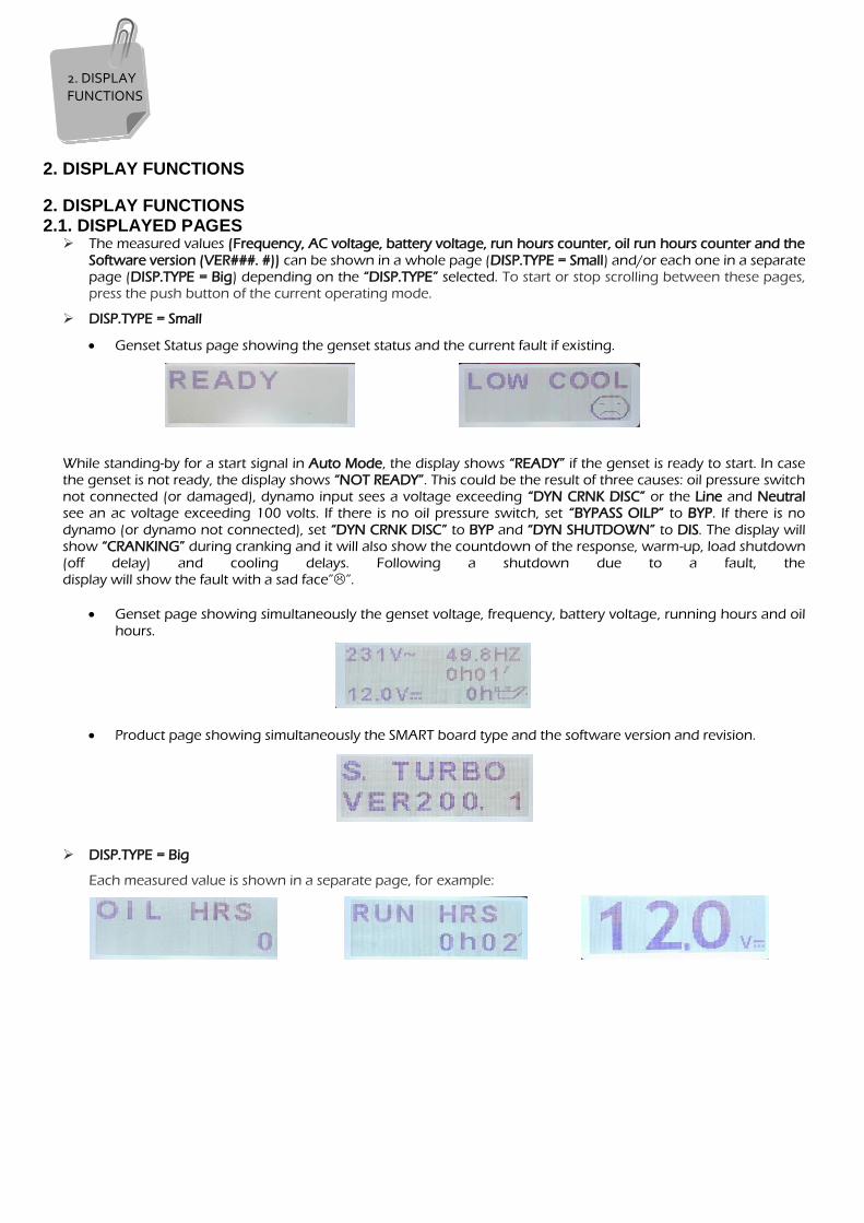
2. DISPLAY FUNCTIONS 2.1. DISPLAYED PAGES The measured values (Frequency, AC voltage, battery voltage, run hours counter, oil run hours counter and the
Software version (VER###. #)) can be shown in a whole page (DISP.TYPE = Small) and/or each one in a separate page (DISP.TYPE = Big) depending on the “DISP.TYPE” selected. To start or stop scrolling between these pages, press the push button of the current operating mode.
DISP.TYPE = Small
Genset Status page showing the genset status and the current fault if existing.
While standing-by for a start signal in Auto Mode, the display shows “READY” if the genset is ready to start. In case the genset is not ready, the display shows “NOT READY”. This could be the result of three causes: oil pressure switch not connected (or damaged), dynamo input sees a voltage exceeding “DYN CRNK DISC” or the Line and Neutral see an ac voltage exceeding 100 volts. If there is no oil pressure switch, set “BYPASS OILP” to BYP. If there is no
dynamo (or dynamo not connected), set “DYN CRNK DISC” to BYP and “DYN SHUTDOWN” to DIS. The display will show “CRANKING” during cranking and it will also show the countdown of the response, warm-up, load shutdown (off delay) and cooling delays. Following a shutdown due to a fault, the display will show the fault with a sad face””.
Genset page showing simultaneously the genset voltage, frequency, battery voltage, running hours and oil
hours.
Product page showing simultaneously the SMART board type and the software version and revision.
DISP.TYPE = Big
Each measured value is shown in a separate page, for example:
2. DISPLAY FUNCTIONS

3. FRONT PANEL DESCRIPTION 3.1 FRONT PANEL LEDS
Two red leds are used to indicate the operating mode.
Genset has one green led. Led OFF means that the genset is not requested to start. Led ON indicates that
genset is running and ready to supply the load.
Six red leds are used to indicate the fault status.
Genset contactor has one yellow led to show its status.
3.2 DETECTED AND SIGNALED FAULTS AND WARNINGS 3.2.1 WARNINGS
High Engine Temperature Warning occurs when the engine temperature switch is active and the 4 seconds fault delay is still being counted.
The Engine Temperature led ( ) turns on due to an engine temperature switch warning.
Low Coolant Level Warning occurs when the coolant switch is detected active and the 4 seconds delay is being
counted. The Coolant Level Led ( ) turns on to indicate this warning.
Low Oil Pressure Warning occurs when the oil pressure switch is detected and the fault delay (2 sec) is being counted. The Oil Pressure led ( ) turns on due to an oil pressure switch warning.
Low Fuel Level Warning occurs when the fuel switch is detected active and the 4 seconds delay is being counted.
The Fuel Level Led ( ) blinks to indicate this warning.
Low Dynamo Voltage Warning occurs when the dynamo voltage decreases below the dynamo shutdown voltage
set by “DYN SHUT DOWN” and the 5 seconds delay is being counted. The Dynamo Voltage ( ) Led turns on to
indicate this warning.
Under Frequency Warning occurs when the frequency goes below the values set in “UNDERFRQ” and the delay
set by “UNDER FRQ DEL” is being counted. The RPM led ( ) turns on to indicate this warning.
Oil Change Warning occurs when the hours since last oil change exceed the value set by “OIL HRS”. This warning is indicated by the blinking of the Oil Pressure Led ( ). To reset the oil change counter, press simultaneously both AUTO and HAND push buttons for 2 seconds.
3.2.2 FAULTS To delete the current fault, press the OFF push button.
Fault Comments
Fail to start Genset fails to start after the maximum number of attempts was reached
High Battery Shuts load and engine after the elapse of the High Battery delay (HIGH BAT DEL)
Low Battery Shuts load and engine after the elapse of the Low Battery delay (LOW BAT DEL)
High Engine Temp. Shuts load and engine due to high engine temperature
Low Coolant Level Shuts load and engine due to low coolant level
Low Oil Pressure Shuts load and engine due to low oil pressure
Low Fuel Level Shuts load and engine due to low fuel level
Low Dynamo Volt Shuts load and engine due to low dynamo voltage
Genset Over Voltage Shuts the load and engine after the elapse of the over voltage delay (OVER VOLT DEL)
Genset Under Voltage Shuts the load and engine after the elapse of the under voltage delay (UNDER VOLT DEL)
Genset Over Frequency Shuts the load and engine after the elapse of the over frequency delay (OVERFREQ DEL)
Genset Under Frequency Shuts the load and engine after the elapse of the under frequency delay (UNDER FRQ DEL)
3. FRONT PANEL
DESCRIPTION

Fail to Start Fault occurs when the engine does not turn on after “ATTEMPTS NBR” cranking attempts. “ATTEMPTS NBR” is set in the menu. The fault is removed when the Remote Control input is recycled. A scan of the six red leds is
initiated to indicate a start fail fault and the LCD will show “START FAIL” with a sad face””. High Battery Fault occurs when the battery voltage exceeds “HIGH BAT VOLT” for a delay set by “HIGH BAT DEL”.
The Battery led ( ) turns on and the LCD indicates a high battery fault by displaying “HIGH BAT VOLT” with a sad face””.
Low Battery Fault occurs when the battery voltage drops below “LOW BAT VOLT” for a delay set by “LOW BAT DEL”. This fault is tested when the engine is not cranking and independent of the fault bypass delay. The Battery led ( ) turns on and the LCD indicates a low battery fault by displaying “LOW BAT VOLT” with a sad face””.
High Engine Temperature Fault occurs when the engine temperature switch is detected on for 4 seconds. The
Engine Temperature led ( ) turns on and the LCD shows “HIGH ENG TEMP” with a sad face””. Genset goes into
cooling if “HI TEMP COOL” is set to ENA.
Low Coolant Level Fault occurs when the coolant switch is detected active for 4 seconds. The Coolant Level Led ( ) turns on and the LCD shows “LOW COOL” with a sad face””.
Low Oil Pressure Fault occurs when the oil pressure switch is detected on for 2 seconds. The Oil Pressure Led ( ) turns on and the LCD shows “LOW OIL PRES” with a sad face””.
Low Fuel Level Fault occurs when the fuel switch is detected active for 4 seconds. The Fuel Level Led ( ) turns on and the LCD shows “INPUT ERROR” with a sad face””.
Low Dynamo Voltage Fault occurs when the dynamo voltage decreases below the dynamo shutdown voltage set by “DYN SHUT DOWN” for 5 seconds. The Dynamo Voltage Led ( ) turns on and the LCD shows “DYNAMO ERROR” with a sad face””.
Over/Under Voltage Fault occurs when the voltage goes above/below the over/under voltage limits set by “OVER
VOLT”/”UNDER VOLT” for a delay set by “OVER VOLT DEL”/”UNDER VOLT DEL”. The RPM Led ( ) turns on and the LCD indicates an over/under voltage fault by displaying “OVER/UNDER VOLT” with a sad face””.
Over/Under Frequency Fault occurs when the engine speed goes above/below the values set in “OVERFREQ”/”UNDERFRQ” for a delay of “OVERFREQ DEL”/”UNDER FRQ DEL”. The RPM Led ( ) turns on for an under frequency fault and blinks for an over frequency fault and the LCD shows “OVER/UNDER FREQ” with a sad
face””.
3. FRONT PANEL
DESCRIPTION

3.3 DESCRIPTION OF STATUS MESSAGES SHOWN ON DISPLAY
Status Message Description
READY Genset ready
FAULT A fault has occurred on the Genset
STARTING IN Engine counting Response delay with count down
PREHEAT Engine preheating with count down
CRANKING Engine cranking
NOT READY Genset not ready
ON LOAD Engine running on load
SHUTTING LOAD Engine shutting Load with count down
COOLING Engine cooling with count down
WARM-UP Engine warming Up with count down
ENGINE RUNNING Engine running
LOW BAT VOLT Low battery fault
HIGH BAT VOLT High battery fault
START FAIL Fail to start fault
LOW OIL PRES Low oil pressure fault
HIGH ENG TEMP High engine temperature fault
INPUT ERROR Input fault
OVER VOLT Genset over voltage fault
UNDER VOLT Genset under voltage fault
OVER FREQ Genset over frequency fault
UNDER FREQ Genset under frequency fault
LOW COOL Genset coolant fault
ENGINE STOP Genset Emergency stop
DYNAMO ERROR Genset dynamo fault
OP OC START Starter output fault
OP OC EV EV output fault
OP OC CONT Contactor output fault
OP OC SPARE Spare output fault
S. TURBO VER —.- Software version with revision number
OIL HRS Oil hours number
RUN HRS Hourmeter
Available only if “SPARE OP” is set to Preheat
3. FRONT PANEL
DESCRIPTION

4. ACCESSING THE MENU
The menu is accessed by pressing either AUTO or HAND push buttons for 3 seconds. Once in menu mode (i.e. scrolling the menu and editing parameters), the AUTO and HAND and STOP push buttons will no longer affect the operating mode of the Smart-TURBO controller. The AUTO push button scrolls down the menu and decrements values. The RUN push button scrolls up the menu and increments values The STOP push button selects the menu item for editing and memorizes the new value. If no buttons are pressed for 25 seconds, the Smart-TURBO will
automatically exit the menu mode.
4. ACCESSING THE MENU

4.1 MENU DESCRPTION
Display Description Range Factory Setting
RESPONSE DEL Response delay 0 to 255sec 5sec
PREHEAT DEL Preheat delay 0 to 255sec 5sec
STARTER TIME Starter time 0 to 255sec 5sec
BET.TRIAL TIME Time between trials 0 to 255sec 12sec
MAINTAIN EV Maintain Electric Valve 0 to (BET.TRIAL TIME-1)
0sec
ATTEMPTS NBR Number of starting attempts 0 to 255 3
FLT BYP TIME Fault bypass delay 0 to 255sec 15sec
WARM-UP DEL Warm-up delay 0 to 255sec 10sec
OFF DEL Load shutdown delay (Off delay) 0 to 255sec 10sec
COOLING TIME Engine cooling time 0 to 255sec 5sec
CRANKING DISC.F Crank disconnect frequency set point 0 to 255Hz 15Hz
OVERFREQ Over frequency set point or disables over frequency DIS, 1 to 255Hz 55Hz
OVERFREQ DEL Over frequency delay 0 to 255sec 2sec
UNDERFRQ Under frequency set point or disables under frequency DIS, 1 to 255Hz 45Hz
UNDER FRQ DEL Under frequency delay 0 to 255sec 5sec
OVER VOLT Over voltage set point DIS, 1 to 255V DIS
OVER VOLT DEL Over voltage delay 0 to 255sec 3sec
UNDER VOLT Under voltage set point DIS, 1 to 255V DIS
UNDER VOLT DEL Under voltage delay 0 to 255sec 5sec
CT RATIO Current Transformer ratio 0/5 to 9999/5 100
OVERLOAD Overload % DIS, 1 to 255% 90%
OVERLOAD DEL Overload delay 0 to 99 sec 10sec
HIGH BAT VOLT High Battery DIS, 1 to 33V 30
HIGH BAT DEL High Battery Delay 0 to 255sec 3sec
LOW BAT VOLT Low Battery DIS, 1 to 33V 8
LOW BAT DEL Low Battery Delay 0 to 255sec 2sec
SOLENOID Selects energize to run or energize to stop by setting time for stop solenoid. When energize to stop, if SPARE OP is not set to CUTOF, the Electric Valve terminal will operate as cut off solenoid output.
RUN, 1 to 255sec RUN
HI TEMP COOL Selects whether to enable cool down after high temperature/Overload shutdown
DIS, ENA ENA
BYPASS OILP. Selects whether to permanently bypass the Oil pressure switch for crank disconnect or whether to bypass it for a preset delay
BYP, 1 to 5sec 1sec
OILP SENS Oil Pressure Sensor type V1=VDO type 1 V5=VDO type 2 MU=Murphy TNE
V1
LOW OPS PREA. Low Oil Pressure Pre-alarm DIS, 1 to 255 PSI DIS
LOW OPS ALA. Low Oil Pressure Alarm DIS, 1 to 255 PSI DIS
TEMP SENS Engine Temperature Sensor type V1=VD0-1 V2=VD0-2 MU=Murphy PT=PT100 TNE
V1
Available only if “SPARE OP” is set to Preheat
4. ACCESSING THE MENU

Display Description Range Factory Setting
HI ETS PREA. High Engine Temp Pre-alarm DIS, 1 to 255 °C DIS
HI ETS ALA. High Engine Temp Alarm DIS, 1 to 255 °C DIS
DYN CRNK DISC Selects whether to permanently bypass the dynamo for crank disconnect or sets the voltage above which cranking stops
bYP, 10 to 26Volts BYP
DYN SHUT DOWN Selects whether to disable the dynamo shutdown or sets the voltage below which there will be a dynamo shutdown
DIS, 5 to 10Volts 5Volts
LOW COOL LOGIC Low coolant input polarity logic NO, NC NC
SPARE OP Selects whether the spare output is used as alarm, preheat or cutoff When CUTOF is selected, Cutoff time must be set in the SOLENOID parameter. In this case, Electric Valve output will retain its standard function.
ALARM PHEAT CUTOF
ALARM
DISP.TYPE Selects the display mode of the measurements BOTH: The measured values are shown in 2 whole pages and each one in a separate page. BIG: displays a page for each measured value. SMALL: The measured values are shown in 2 whole pages. KWh value is shown in a separate page
BOTH, BIG, SMALL BOTH
CONTRAST LCD Display Contrast 0 to 63 7
OIL HRS Sets the number of hours before alerting for an oil change DIS, 1 to 255hours 150
HR. METER Edits the run hour counter 0 to 65530 0
FACTORY RST Load Factory settings --- ---
VIEW FAULTS View Fault Log --- ---
ERASE FLTS Erase Fault Log --- ---
EXIT Exit the menu --- ---
A three digit password (000) is required to access the hour counter or Kwh or to reset factory settings. Display shows E on the leftmost digit. Use the HAND (increment) and AUTO (decrement) push buttons to scroll to the desired number, use the STOP push button to select the digit. When the digit is entered, it is replaced by C. Repeat the previous steps for the second and third digit of the password. If the entered password is correct and it was an hour/Kwh counter modification order, the most significant digit of the hour/Kwh counter will start blinking. Use the HAND (increment) and AUTO (decrement) push buttons to scroll to the desired number, use the STOP push button to select the digit. When the digit is entered the next digit starts to blink. If the entered password is correct and a factory settings reset was requested, select YES in order to confirm the reset. Not affected after a load factory settings. Viewed and accessed only when at least one fault is already saved.
4. ACCESSING THE MENU

5. TECHNICAL SPECIFICATION 5.1 SPECIFICATION
Operating voltage 8 to 28vdc
Signal voltage range 50 to 250vac
Outputs 1A 50V
Dimensions (WidthxHghtxDepth) 72x72x32 mm
6.2 ABSOLUTE MAXIMUM RATINGS
Supply voltage 8-30Vdc
Supply voltage 8-30Vdc
Signal voltage 280vac
Outputs 1.4A
Operating temperature -30 to 70°C
5.
TECHNICAL
SPECIFICATION

6. FIRMWARE UPGRADE 6.1 FIRMWARE UPGRADE USING PC
1. Plug in the USB cable to the SMART device before turning power on 2. Turn on power of the SMART device. All the LEDs on the front start blinking.
3. Please visit http://www.sascontrollers.com/applications and choose SAS Firmware Upgrade Driver or through the SASPTool desktop application.
6.1.1 INSTALLING THE SAS DEVICE USB DRIVER The first SMART plugged into the PC USB port may not launch an automatic start. In this case, right-click my computer and choose properties. On the left side of the window, click on Device Manager. The “SAS DEV” device will appear in Other Devices, right-click it and choose “Update Driver Software”.
Firmware upgrade is not applicable in Software version SGT10B302_TURBO_STM103C6.
This will be implemented only one time when the first SMART is connected to PC through USB
6.
FIRMWARE
UPGRADE

Select “browse my computer” and select the downloaded windows driver.
The Driver SETUP procedure will be done only once for Windows. So, the driver of any new SMART connected to the PC USB port will be installed automatically.
6.
FIRMWARE
UPGRADE

6.1.2 INSTALLING THE FIRMWARE UPGRADE SOFTWARE In order to upgrade firmware on site, visit http://www.sascontrollers.com/applications and choose Desktop
Firmware Upgrade App. 1. 64 and 32 bit folder will be downloaded respectively. 2. Run the executable file.
6.1.3 FIRMWARE UPGRADE PROCESS Run “SAS_PTool v.2.0” application.
Click Browse SAS File button to choose the *.sas file that will be used to upgrade the firmware. A Footnote will appear showing the file name, the software version and its date:
Click “Start Upgrade”. The upgrade progress is shown as below:
6.
FIRMWARE
UPGRADE
6.
FIRMWARE
UPGRADE
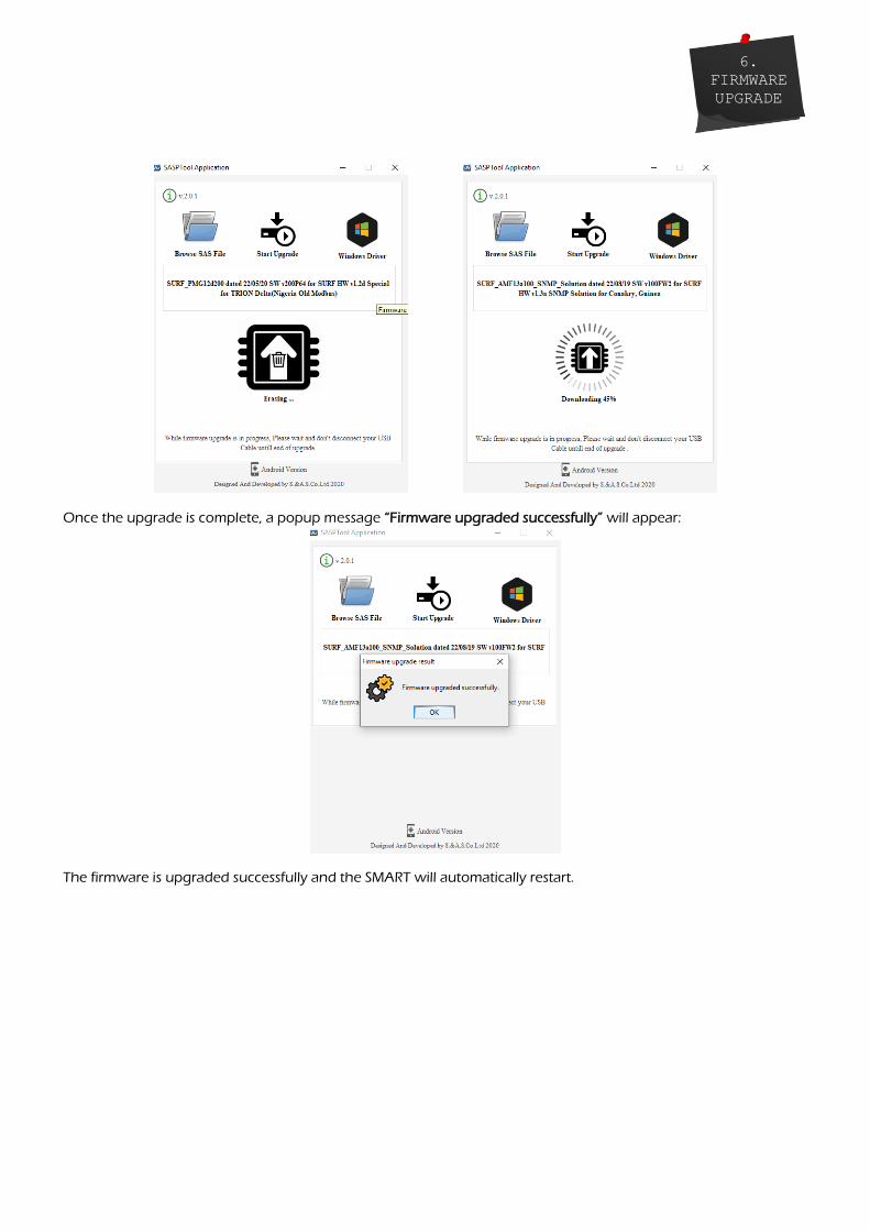
Once the upgrade is complete, a popup message “Firmware upgraded successfully” will appear:
The firmware is upgraded successfully and the SMART will automatically restart.
6.
FIRMWARE
UPGRADE

6.2 FIRMWARE UPGRADE USING GOOGLE STORE ON SMART PHONE 6.2.1 INSTALLING THE SASPTOOL FIRMWARE APPLICATION ON THE MOBILE
Search for the application “SASPTool” on google store and install it, or follow the link below: https://play.google.com/store/search?q=SASPTool.
6.2.2 FIRMWARE UPGRADE PROCESS In order to upgrade firmware from a mobile, follow the below steps: 1. Run “SAS_PTool” application from the mobile.
The below window appears showing all *.sas files already saved.
2. Power off the SMART board
3. Use a USB cable to connect board to the mobile.
4. Turn SMART on.
The following window will appear:
6.
FIRMWARE
UPGRADE
Press this button to refresh the firmware list.
Press this button to create SAS folder.
Press this button to go back one directory.

5. Click on the Connect button. The following window will appear showing that a SAS Device is now
connected:
6. Click on the SAS file that you need to download.
A Popup window will appear showing the file name, its description and its date:
6.
FIRMWARE
UPGRADE

7. Click Yes. The download will start:
Once the download is complete, the message “Firmware Downloaded successfully” will appear:
6.
FIRMWARE
UPGRADE

8. Disconnect the USB cable.
If you desire to delete any SAS file from the mobile list, press on the filename until a Popup window appears
showing you multiple choices and then click on Delete.
6.
FIRMWARE
UPGRADE

7. APPENDIX A This section contains the wiring diagram of the SMART- TURBO
7. APPENDIX
A

1
1
2
2
3
3
4
4
5
5
6
6
D D
C C
B B
A A
LINE
NEUTRAL
SPRE OP
CONTACTOR
(-)Vbat
(+)Vbat
STARTER
ELECTRIC VALVE
OIL PRESSURE SWITCH
TEMPRETURE SWITCH
DYNAMO
FAULT
COOLANT PROBE
REMOTE CONTROL
DYNAMO EXCITATION
OPS
ETS
2 10R(EV)
2 10R(St)
FUSE
2 10R(Ld)
2 10R(Preheat/Alarm)
NB: R(Preheat/Alarm), R(Ld), R(St) and R(EV) relays should all be DC relays with their coil voltage equal to the battery voltage
R(G Ld)
G
NTSR
NTSR
LOAD
12
210
C(G Ld)
FUSE
34
56
Smart Series - TURBO
5 - 33 Vdc
C(G Ld)

WHICH GENERATOR CONTROLLER IS RIGHT FOR YOU?
Smart Turbo v1.2 Smart GT v1.0 Surf LT v1.0 Surf 1.2c
Automatic engine starting and stopping
Automatic mains failure — — User Access 3 Push Buttons 3 Push Buttons 8 Push Buttons 5 Push Buttons Dimensions
(WidthxHeightxDepth) 72x72x32 mm 72x72x32 mm 208x160x32 mm 196x144x33 mm
Panel cut out 68.5x68.5 mm 68.5x68.5 mm 184x139 mm 182x137 mm Number of Phases 1 Phase 1 Phase 1phase/3Phases 1phase/3Phases
Digital Outputs 4 4 6 10 Digital Inputs 5 5 5 5 Analog Inputs — 2 4 4
Voltage Measurement 1 L-N 1 L-N 3 L-N, 3L-L 3 L-N, 3L-L Frequency
Measurement
Current Measurement — Power Measurement — Energy Measurement —
Run hours counter Oil run hours counter Over / Under voltage alarm and shut down
Over / Under frequency alarm and
shut down
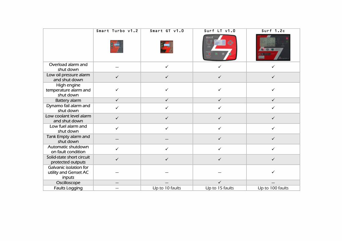
Smart Turbo v1.2 Smart GT v1.0 Surf LT v1.0 Surf 1.2c
Overload alarm and shut down —
Low oil pressure alarm and shut down
High engine temperature alarm and
shut down
Battery alarm Dynamo fail alarm and
shut down
Low coolant level alarm and shut down
Low fuel alarm and shut down
Tank Empty alarm and shut down
— —
Automatic shutdown on fault condition
Solid-state short circuit protected outputs
Galvanic isolation for utility and Genset AC
inputs — — —
Oscilloscope — — — Faults Logging — Up to 10 faults Up to 15 faults Up to 100 faults
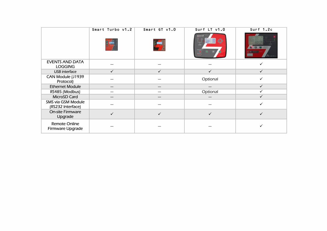
Smart Turbo v1.2 Smart GT v1.0 Surf LT v1.0 Surf 1.2c
EVENTS AND DATA LOGGING — — —
USB interface CAN Module (J1939
Protocol) — — Optional
Ethernet Module — — — RS485 (Modbus) — — Optional
MicroSD Card — — — SMS via GSM Module
(RS232 Interface) — — —
On-site Firmware Upgrade
Remote Online Firmware Upgrade — — —


