
Auto Plate Manual
83
User’s Manual Release 8 Autoship Systems Corporation Suite 312 - 611 Alexander Street Vancouver BC V6A 1E1 Canada Copyright 2004 Autoship Systems Corporation Windows TM is a trademark of Microsoft Corporation AutoCAD® is a trademark of Autodesk, Inc. Aut o p plate For Windows TM
-
Upload
caicararioorinoco -
Category
Documents
-
view
62 -
download
3
Transcript of Auto Plate Manual

User’s Manual Release 8
Autoship Systems Corporation Suite 312 - 611 Alexander Street Vancouver BC V6A 1E1 Canada
Copyright 2004 Autoship Systems CorporationWindows TM is a trademark of Microsoft CorporationAutoCAD® is a trademark of Autodesk, Inc.
Autopplate For WindowsTM

Information contained in this document is subject to change without further notice. No part of this document may be reproduced or transmitted in any form, or by any means, electronic of mechanical, for any purpose, without the express permission of Autoship Systems Corporation.
Windows is a trademark of Microsoft Corporation. AutoCAD is a trademark of Autodesk Inc. All other product names are trademarks, registered trademarks, or service marks of their respective owners. Autoship Systems Corporation cannot attest to the accuracy of this information. In addition, terms suspected of being trademarks, registered trademarks, or service marks have been appropriately capi-talized. Use of a term in this book should not be regarded as a validity of any trade-mark, registered trademarks, or service mark.
Autoship Systems CorporationSuite 312611 Alexander StreetVancouver, B.C. V6A 1E1 Canada
Tel: (604) 254-4171Fax: (604) 254-5171www.autoship.com
Copyright 2004 Autoship Systems Corporation. All right reserved
Table of Contents
Chapter 1 - Getting Started 1
Introducing Autoplate 1
System Requirements 2
Installing Autoplate 3• System Initialization - Wise Installation Wizard• Autoplate Setup Program
Starting and Exiting Autoplate 5• Starting• Exiting
Chapter 2 - Quick Overview 7
Chapter 3 - Reference 11• What is Plate Expansion?
Overview 12
The Autoplate User Interface 13• The Menus and Help system• New Control Bar Icons
Points and Curves in Autoplate 14• New Curve Options
Preparing an Autoship Project for Autoplate 15
Starting a New Autoplate Project 16
i

Stock 17
Setting Up a Classification 18
Plate Boundaries 19• Requirements for Plate Boundaries• Tips for Creating Plate Boundary Curves
Creating a Plate 21
Plate Selection 22
The Plate Viewer 23
Expansion 24• Directionality• Condition• Extra Stock• Mesh• Expansion Failure
Templates 27
Pin Jig 28
Reports 29
Panels 30• Creating a New Panel• Selecting Panels• Creating a Panel Pin Jig
Export 33• Plate DXF• Panel DXF• Shell Expansion
Invalidation and Regeneration of Plates 37
ii

Plate Deletion 38
Switching between Autoship and Autoplate 38
References 38
Chapter 4 - Tutorial 39• Preliminary Considerations
Starting a New Autoplate Project 40
Defining Plate Stock 42
Plate Classification 43
Setting Up a Baseline 45
Laying Out Seams and Butts 47
Defining a Plate 52
Defining Templates 61
Defining Pin Jig Settings 63
Defining Plates on the Stern Bulb 64
Defining Plates on the Bow Flare 69
Defining a Panel and its Pin Jig 73
DXF Output 75• Plate Drawings• Panel Drawings• Shell Expansion
Generating Reports 76
iii

Getting Started
Chapter 1
Getting Started
Introducing Autoplate
Autoplate is a tool for creating hull plates for ships. It offers the following features:
• automates many of the processes involved in defining plate boundaries • performs plate expansion and produces forming information • generates templates and pin jig data • allows assignment of stock type to plates• provides 2D and 3D DXF output• generates shell expansion DXF drawings• provides a classification system for the organization of plate information• creates pin jig data for panels made of adjacent plates• calculates plate weights and areas
Autoplate is closely tied to the Autoship hull design program. It accepts Autoship project files as input and has basically the same main screen, controls and menus. In this manual it is assumed that the reader is familiar with Autoship and with the Windows operating system. If any terms or features in this manual are unfamiliar, please consult the Autoship manual.
The system incorporates security features which are designed to prevent acciden-tal modification of a ship design and the plating of trimmed-away portions of sur-faces. Autoplate reads but does not modify Autoship project files; the Autoship operator designates what objects are to be plated.
1

Chapter 1
System RequirementsAutoplate is a 32 bit Windows program, which will install and run under Windows 95 or Windows NT 4.0 (service pack 3 or later). Other requirements include:
* Operation is possible at 256 colors, but for rendering to function correctly 32k colors or more are needed.
Operating System Windows 98Windows NT4 SP6a or laterWindows 2000 Windows XP Professional SP1
Processor Pentium
Memory 256
Video 1024 X 768 with True Color
Hard Disk 100 MB Free
2
Installing Autoplate
Installing Autoplate
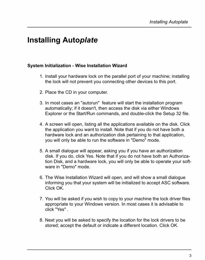
System Initialization - Wise Installation Wizard
1. Install your hardware lock on the parallel port of your machine; installing the lock will not prevent you connecting other devices to this port.
2. Place the CD in your computer.
3. In most cases an "autorun" feature will start the installation program automatically; if it doesn't, then access the disk via either Windows Explorer or the Start/Run commands, and double-click the Setup 32 file.
4. A screen will open, listing all the applications available on the disk. Click the application you want to install. Note that if you do not have both a hardware lock and an authorization disk pertaining to that application, you will only be able to run the software in "Demo" mode.
5. A small dialogue will appear, asking you if you have an authorization disk. If you do, click Yes. Note that if you do not have both an Authoriza-tion Disk, and a hardware lock, you will only be able to operate your soft-ware in "Demo" mode.
6. The Wise Installation Wizard will open, and will show a small dialogue informing you that your system will be initialized to accept ASC software. Click OK.
7. You will be asked if you wish to copy to your machine the lock driver files appropriate to your Windows version. In most cases it is advisable to click "Yes" .
8. Next you will be asked to specify the location for the lock drivers to be stored; accept the default or indicate a different location. Click OK.
3

Chapter 1
9. A warning message will appear, notifying you that Setup will attempt to install the lock driver. It is advisable that you check to ensure your hard-ware lock is installed correctly; if it is not, then the program will only run in Demo mode.
Autoplate Setup Program
10. The Autoplate Setup program will now start. An information message will appear first. Ensure all other Windows programs are closed, and click Next.
11. Accept the default installation location, or use the Browse feature to specify another location.
12. A dialogue will appear that asks if you want to create backup copies of all files replaced during installation. Clicking "Yes" means that, if you unin-stall the software, you can "roll back" to a previous condition. If you click "No", then you can uninstall but will not be able to roll back to a previous state.
13. Follow the remaining instructions to complete the installation
4
Starting and Exiting Autoplate
Starting and Exiting Autoplate
Starting
Click Autoship/Autoplate start menu.
The Autoplate splash screen will appear. After the program has finished loading the main screen will appear.
Exiting
There are two ways to exit Autoplate:
1. Using the File menu:
Select the Exit option from the File menu. You will be prompted to save your current work.
2. Using the Windows close box:
Double-click the close box at the top left of the main screen. You will be prompted to save your current work.
5

Chapter 1
6

Quick Overview
Chapter 2
Quick Overview
This chapter provides a quick, step-by-step approach to producing plates. The numbers in parenthesis indicate later sections of the manual which provide detailed information.
At the highest level, the plate production process can be summarized as follows:
Steps to Create and Expand a Plate:
1. The surfaces to be plated are created in Autoship and the project is saved as a PRx file.
2. Curves are created on the surfaces either in Autoship or Autoplate.3. In Autoplate, curves meant to be the seams (boundaries) of a plate are high-
lighted and the plate is created by clicking between them on the surface. 4. The plate is expanded and other output data are generated.
In more detail:
1. In Autoship, prepare the project for plating (3.4):•Ensure that all objects (surfaces and polyobjects) to be plated have their
normal vectors pointing outward.•Gather these objects into one or more groups.•Optionally establish a baseline containing frame locations.•Save the PR2 (Autoship 6) or PR3 (Autoship 7) file.
2. In Autoplate, start a new plating project (3.5):•Start Autoplate, select File - New and select the PRx file.•Use Plate - Group to select the group to be plated.•Use File - Save As to create the new PLA file in the desired directory.
7
Chapter 2
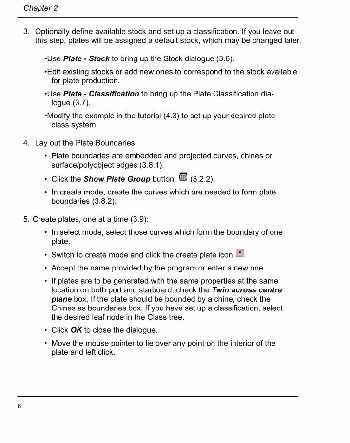
3. Optionally define available stock and set up a classification. If you leave out this step, plates will be assigned a default stock, which may be changed later.
•Use Plate - Stock to bring up the Stock dialogue (3.6).•Edit existing stocks or add new ones to correspond to the stock available
for plate production.•Use Plate - Classification to bring up the Plate Classification dia-
logue (3.7).•Modify the example in the tutorial (4.3) to set up your desired plate
class system.
4. Lay out the Plate Boundaries:• Plate boundaries are embedded and projected curves, chines or
surface/polyobject edges (3.8.1).
• Click the Show Plate Group button (3.2.2).• In create mode, create the curves which are needed to form plate
boundaries (3.8.2).
5. Create plates, one at a time (3.9):• In select mode, select those curves which form the boundary of one
plate.
• Switch to create mode and click the create plate icon .• Accept the name provided by the program or enter a new one.• If plates are to be generated with the same properties at the same
location on both port and starboard, check the Twin across centre plane box. If the plate should be bounded by a chine, check the Chines as boundaries box. If you have set up a classification, select the desired leaf node in the Class tree.
• Click OK to close the dialogue.• Move the mouse pointer to lie over any point on the interior of the
plate and left click.
8

Quick Overview
6. Once a plate is created, you can view its properties at any time:• Use Plate - Select to bring up the Plate Select dialogue (3.10).• Select just one plate.• Use Plate - View to bring up the Plate Viewer dialogue (3.11).
7. Expand plates (3.12):• In the Plate Select dialogue choose one or more plates to be
expanded with the same set of options.• Use Plate - Expand to bring up the Expand dialogue.• Select the options: Directionality (3.12.1), Condition (3.12.2), Extra
Stock (3.12.3) and Mesh Edge Tolerance (3.12.4).• Click OK. As each selected plate is being expanded, its name is dis-
played in the bottom left corner of the dialogue.
8. Create templates and/or pin jigs. These are optional aids to plate fabrication:• In the Plate Select dialogue choose one or more plates.• Use Plate - Templates (3.13) or Plate - Pin Jig (3.14) to bring up
the relevant dialogue. • Choose options and click OK.• The program calculates templates/jigs for all selected plates using
the same options.
9. Create DXF output files (3.17):• Select the plate(s) you want to output.• Use File - Export - Plate DXF to bring up the Plate Output to DXF
dialogue (3.17.1).• Check the boxes for each item you want included in the DXF draw-
ing. 2D and 3D are output to separate files for each selected plate.• Each item is on a separate layer. To set a layer colour, click the box
to left of its check box. Clickclick the desired colour in the colour dia-logue.
• Choose output units.
9
Chapter 2
10. Create shell expansion (3.17.3):• If you wish to have any plates shown on the drawing, select them.• Use File - Export - Shell Expansion to bring up the Shell Expan-
sion DXF dialogue.• Select items and set colours as above.• If you wish the drawing to be produced to some tolerance, check the
Do Refinement box and enter a value for the tolerance.
11. Create and output panels (3.16). If plates are to be assembled into panels Autoplate will produce data for setting up a pin jig to position them:
• Use Panel - New to bring up the New Panel Dialogue (3.16.1).• Accept the default name or enter a new one.• In the All Plates list select those to be in the new panel.• Click Add Selected.• In the case that some plate is included which should not be, select it
in the In Panel list and click Remove Selected.• Optionally, enter a comment. Click OK.• Having created a panel, use Panel - Select to bring up a dialogue
where it may be selected (3.16.2).• Use Panel - Pin Jig to bring up the Panel Pin Jig dialogue (3.16.3).• Select the appropriate options and use the Align controls to adjust
the jig pin locations to the panel. Click OK.• Select panels for export and select File - Export - Panel to bring up
the Panel DXF dialogue. Choose options (3.17.2) and click OK.
10

Reference
Chapter 3
Reference
What is Plate Expansion?
When a surface has compound curvature (nonzero Gaussian curvature) and flat material is to be made to conform to a patch of that surface, the material must be stretched or shrunk. The resulting relative change in distance between neighbour-ing points is called strain. The process of calculating the required strain is called expansion, and performing this calculation is one of Autoplate's principal func-tions. Note that if the surface patch is developable, the strain will be zero over that patch. Once strain has been calculated, the program can map plate boundaries and internal features, such as embedded curves, from the curved surface onto the flat.
This process closely resembles geographical mapping in which a flat representa-tion of the doubly-curved earth's surface is generated. As everyone knows, there are many such mappings: Mercator's, polar stereographic, Cassini, etc. The dis-tinction among these is not that any one is more correct than another, but that one may be particularly useful for a given purpose. For example, Mercator's is useful for mapping the whole globe without any cuts except at the poles while the equal-area mappings are useful for seeing relative land area.
For any one hull plate many strain distributions are possible. This is reflected in the industry where each commercial program uses a different method (Lamb, 1994), some of which are computer implementations of old manual methods. As in geographical mapping, there is no one correct method. The choice is based on degree of usefulness for plate fabrication. The method selected should also be fast enough to expand many plates in a reasonable time, and capable of correctly completing its calculations for almost any input shape.
Autoplate, which was designed with these objectives in mind, uses a new, reason-ably fast algorithm which produces very smooth mappings. The resulting strain is well distributed over the plate and will result in easy manufacture.
11
Chapter 3
Overview
Autoplate accepts surface shape information only in the form of Autoship PRx (PR2 for Autoship 6, PR3 for Autoship 7) files. Plate boundaries (seams and butts) are curves which are embedded in or projected onto Autoship surfaces. These curves may be created either in Autoship or Autoplate, or both. Autoplate does not modify PRx files; it has its own binary file type (extension PLA) in which it can save, among other entities, points and curves added to the project con-tained in the PRx file.
Having suitably prepared a project in Autoship, you read it into Autoplate, set up a classification tree (if desired) and assign stock to the classes. You are then ready to create any boundary curves which are not already in the project and then to define plates. Curve generation proceeds exactly as in Autoship.
A plate is defined by selecting those curves which form its boundary and then clicking in the plate interior. The program searches for a closed boundary path, formed from sections of the selected curves and surface/polyobject edges. If such a path is found, a triangular mesh is generated over the plate.
Having defined and selected a plate you then generate its expansion. This involves choosing among several options and specifying what if any extra stock you want on the plate boundaries. Once the expansion is performed you can use the Autoplate viewer to evaluate the result.
Templates, plate pin jig data and panel pin jig data are generated in separate operations.
You may choose to export the results in DXF format and/or generate reports for each plate individually and for all plates. A shell expansion view may also be out-put as DXF.
12

Overview
The Autoplate User Interface
The Autoplate main screen is almost identical to that of Autoship, however Auto-plate has some different main menu items as well as additional buttons on the control bar. Autoplate does not support the creation or editing of surfaces and polyobjects, so the select, edit and create mode tool icons specific to them are absent
The Menus and Help system
Most of the Autoship menus are present in Autoplate. The Files menu has no import item and export is limited to plate, panel and shell expansion DXF. The Edit menu is simpler in Autoplate. Two new top menu items, Plate and Panel, bring up menus unique to Autoplate. The items in these menus will be discussed individually in later sections.
Most of the dialogue boxes unique to Autoplate contain a Help button. Clicking this will bring up a help topic in which the use of the dialogue is described.
New Control Bar Icons
The Show Plate Group button has no correspondence in Autoship. Like other
buttons on the tool bar it has two states, up and down . When this button is down, only the objects in the plate group, plus any curves hosted by these objects, are visible. Autoplate searches all curves in the project to find any which are embedded in or projected onto surfaces in the group, or surfaces which are the origin for polyobjects in the group. Only curves which are visible will be dis-played. Visibility may be set in the attributes dialogue. This button must be in its down state to define plates.
The Show Plates button is an addition to the group of "Show" buttons. When it is in the down state plates are drawn on the screen. How a plate is shown depends on the setting of the Plates - Show Names menu item. If it is checked, the plate outline is drawn and the plate name is drawn at the plate centre. The name colour indicates the plate status: green is valid expanded and red is any-thing else. If Show Names is not checked, the plates' triangular meshes are drawn. Selected plates are drawn in a highlight colour. The Show Plate Group button must be up for plates to show.
13

Chapter 3
Points and Curves in Autoplate
All of the Autoship facilities for creating and editing points and curves are avail-able in Autoplate. No object created in Autoship can be edited or deleted in Auto-plate, but any new objects are fully editable. There is one change in curve creation: on the embedded and projected tabs of the Create Curve dialogue box, you may specify the host as a polyobject, in addition to curve or surface. This choice is necessary for plate boundary creation. It signifies that the actual host will be the surface from which the polyobject was created.
New Curve Options
In order to facilitate plate layout, several new curve creation options have been added to Autoship and Autoplate.
• Type 2 Projected Curve: The Projected tab in the new curve dialogue pro-vides the option of Type 1 or Type 2 projected curves. The former is the orig-inal, unchanged, Autoship projected curve. Type 2 projected curves differ in that they are derived from a process equivalent to making an extruded sur-face from the source curve and intersecting it with the host surface. This may produce more than one projected curve and such curves may encircle the host surface. Type 2 curves are embedded and editable. It is strongly recommended that you use Type 2 rather than Type 1 projected curves when designing plate boundaries.
• Geodesic Offset Curve: This is a new tab in the new curve dialogue. Given a source curve, side and offset distance, the program creates a new curve offset a constant geodesic distance (i.e. measured along the surface) from the source curve. This is useful for laying out plates of constant, given, width. Note that if the plate forming involves shrinking, the starting width of the plate on flat stock may be larger than the specified offset distance. The resulting curve is embedded and editable.
• Curve from surface row/col: This curve may now be either embedded or free. This facilitates the placement of plate boundaries on knuckle lines.
• Curve Match: When the source curve is embedded (including planar-embedded and geodesic offset) in or projected onto a surface, the match curve may be specified as embedded. If a Type 1 projected curve does not meet a surface edge or has some extraneous shape, you can match it with an embedded curve and edit the latter to the desired shape.
14

Preparing an Autoship Project for Autoplate
Preparing an Autoship Project for Autoplate
The surfaces and polyobjects to be plated must be incorporated into one or more groups in Autoship. Although you may create some or all of the plate boundary curves in Autoship, there is no need to include these in the group. Polyobjects which were imported or generated as text or primitives cannot be plated. If a poly-object is to be plated, the surface from which it was generated must still be present in the project and must not have been changed since the polyobject was created. This surface should not be included explicitly in the plating group.
All surfaces in the group should have their normal vectors pointing outward. The same is true of the surfaces from which polyobjects are derived. In fact, the latter should be correctly oriented before generating the polyobject.
The full generality of Autoship groups is available for this purpose, including clon-ing and transforms.
You may create more than one group to be plated, however, objects to be plated should exist only in one group. In Autoplate each group is handled separately; there is no facility for making a plate cross group boundaries.
You may establish frame locations (Settings - Preferences - Baseline) in Auto-ship or Autoplate. If a baseline is defined in Autoship, it cannot be changed in Autoplate.
15

Chapter 3
Starting a New Autoplate Project
The File - New menu item in Autoplate brings up a dialogue for choosing an Auto-ship PRx file. There is no way to do any work in Autoplate until a PRx file has been loaded. When you save an Autoplate (PLA) file, it contains a reference to the originating PRx file. The latter file must be available to Autoplate every time the plate project is loaded. If it is not in its original path you will be prompted to enter a location for it.
Once an Autoship project is loaded, you must indicate which group is to be plated. This is done through the Plate - Group menu item, which brings up a dialogue with a list of all groups in the project. When you have chosen a group from this list, the operations of defining and expanding plates may begin.
The next two sections describe Autoplate's facilities for specifying stock and set-ting up a classification tree. Both of these are optional. You can define and expand plates using the default stock and root classification. At a later time you can set up a classification and change stock assignments. However, because the expansion calculations depend on plate thickness, changing the stock assigned to a plate invalidates its expansion. For this reason it is advisable to enter the var-ious stock materials before calculating any expansions.
16

Stock
Stock
Autoplate maintains a library of stock material. This is accessible through the Plate - Stock menu item. The Plate Stock dialogue allows you to view the proper-ties of stock already in the library and to add new stock.
Stock has a name, material, specific gravity, thickness, length and width. Other properties, such as grade of material, may be incorporated into the name.
To create a new stock specification, start by entering its name. Then select a material. If the list of materials does not contain an appropriate entry, create one by entering its name and specific gravity. Enter the desired plate thickness and maximum dimensions, then click Save.
If you wish to delete a stock from the library, you must first ensure that no plate has that stock assigned to it.
17
Chapter 3
Setting Up a Classification
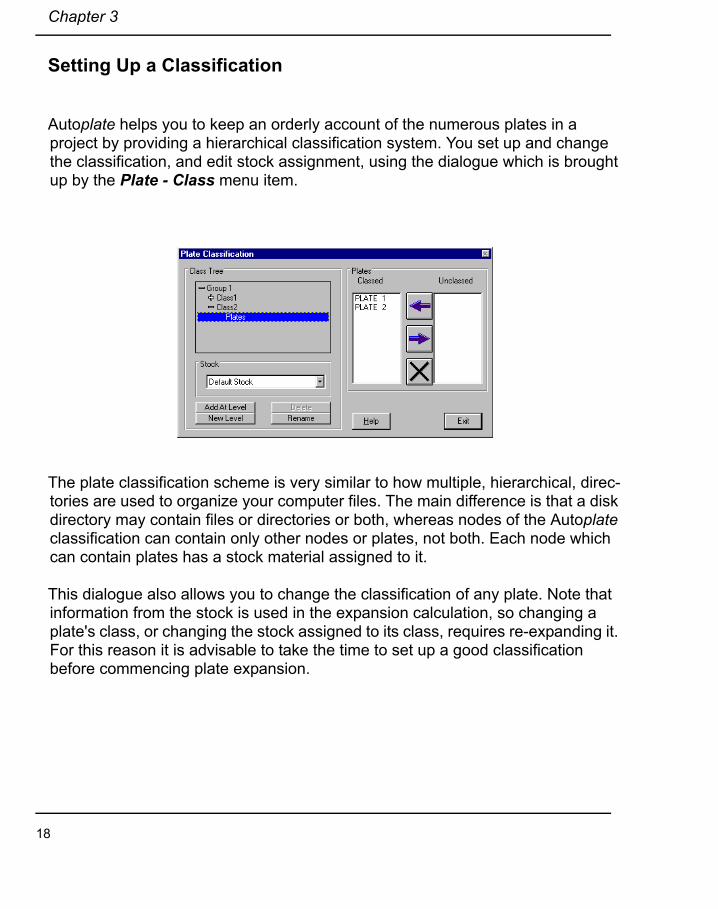
Autoplate helps you to keep an orderly account of the numerous plates in a project by providing a hierarchical classification system. You set up and change the classification, and edit stock assignment, using the dialogue which is brought up by the Plate - Class menu item.
The plate classification scheme is very similar to how multiple, hierarchical, direc-tories are used to organize your computer files. The main difference is that a disk directory may contain files or directories or both, whereas nodes of the Autoplate classification can contain only other nodes or plates, not both. Each node which can contain plates has a stock material assigned to it.
This dialogue also allows you to change the classification of any plate. Note that information from the stock is used in the expansion calculation, so changing a plate's class, or changing the stock assigned to its class, requires re-expanding it. For this reason it is advisable to take the time to set up a good classification before commencing plate expansion.
18
Plate Boundaries
Plate Boundaries
Requirements for Plate Boundaries
Autoplate will create and expand plates of three or more sides. The curves that you select, plus any intersected surface or polyobject edges, plus (optionally) chines, must form a closed boundary having at least three corners. The following count as corners (consider chines to be curves):
Knuckles on the boundary curves.
• The mutual end point of a closed curve.
• The point where a curve meets a boundary of the surface or polyobject.
• The point where two curves cross or join, and
• The point where one curve terminates on another curve.
Only selected curves will be part of the boundary definition. Any other curves, even if they cross the plate, will not be considered.
Autoplate will not create plates which have concave boundaries. A boundary is concave if the polygon made of straight lines joining corners has any edge which, if extended as a straight line, penetrates the polygon interior. For instance, imag-ine a four sided polygon where the inside angle between two adjacent legs is more than 180 degrees. Autoplate will handle some boundaries which have con-cave curved edges between corners.
When a curve and surface edge are intended as plate boundaries, and the curve does not meet the edge, one possible error message is "Boundary Is Concave". If you get this message, and the boundary is not concave in the sense described in the last paragraph, check the ends of relevant curves.
19
Chapter 3
Tips for Creating Plate Boundary Curves
One way to lay out plate boundaries is by making straight space curves and pro-jecting them onto the surface. If you use Type 1 projected curves this does not work well when the surface is tangent to the projection direction anywhere along the curve. When such tangency exists, the projection operation is not properly defined and the resulting projected curve may be wiggly and may even turn back on itself or may not contact the surface edge. This is likely to happen with a side-projected curve at the bow or stern. If a projected curve seems to meet a surface edge but you get an error message when trying to create a plate from it, suspect this as a cause.
There are several ways to avoid this problem.
1. Use Type 2 projected curves.
2. Make a planar-embedded curve running over the whole region of interest. Although these curves can be hard to edit, this solution is preferred over 3.
3. Project two Type 1 curves in different views. An example is one source curve at constant y and z (horizontal, parallel to the centre plane), projected from the side and another curve at constant x and the same z, projected in body plan. Then the two projected curves together cover the whole region of interest. For any given plate, use the curve which is valid on that part of the surface as a boundary.
4. Once you have one good curve established, create others as geodesic off-set curves.
20

Creating a Plate
Creating a Plate
1. Ensure that a plate group has been selected and that the Show Plate Group button is down.
2. In select mode, select the curves which will form the plate boundary.
3. Switch to create mode.
4. Click the Create Plate button .
5. Click over any point on the desired plate interior.
6. When the new plate dialogue appears enter a name for the plate (or choose the default) and select a class.
7. If the ship is symmetric about a centre plane, you may create plates for both sides by checking the Twin across centre plane box.
8. If you want chines to be considered as boundary curves, check the Chines as boundaries box
9. Click OK.
21

Chapter 3
Plate Selection
The Plates - Select menu item provides access to the Plate Select dialogue. Using this you may select one or more plates. The Plates - View menu item is enabled only if just one plate is selected.
Several program operations apply to one or more selected plates at once: expan-sion, template specification, pin jig specification, DXF export, appearance on shell expansion.
The list box in this dialogue also provides an indication of the plate state. See the help item and the section "Invalidation and Regeneration of Plates", 3.18 below, for details.
22

The Plate Viewer
The Plate Viewer
If one and only one plate is selected, the menu item Plates - View is enabled and selecting it brings up the plate viewer dialogue. This provides you with detailed information about the selected plate. Please see the Help item for more informa-tion.
The dialogue has 3 tabs:
ImageThis tab contains several option buttons by which you choose what image to view. Several require that the plate has been expanded, and Templates and Template Layout require that templates have been specified.
DataThis provides several pieces of quantitative information about the plate, although most are available only for expanded plates. Any com-ments you enter in the text box are saved with the project file and will appear the next time you view the plate's data.
MetricsThis shows information about plate shape, both graphically and as text. The purpose of this information is to enable you to judge whether a plate is so curved that it should be subdivided. This infor-mation is available before and after expansion.
In the viewer, drawings are as seen from the outside of the hull.
23
Chapter 3
Expansion
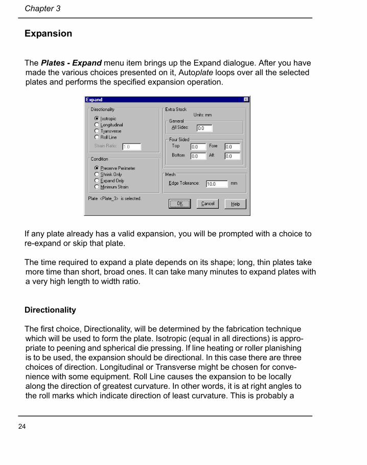
The Plates - Expand menu item brings up the Expand dialogue. After you have made the various choices presented on it, Autoplate loops over all the selected plates and performs the specified expansion operation.
If any plate already has a valid expansion, you will be prompted with a choice to re-expand or skip that plate.
The time required to expand a plate depends on its shape; long, thin plates take more time than short, broad ones. It can take many minutes to expand plates with a very high length to width ratio.
Directionality
The first choice, Directionality, will be determined by the fabrication technique which will be used to form the plate. Isotropic (equal in all directions) is appro-priate to peening and spherical die pressing. If line heating or roller planishing is to be used, the expansion should be directional. In this case there are three choices of direction. Longitudinal or Transverse might be chosen for conve-nience with some equipment. Roll Line causes the expansion to be locally along the direction of greatest curvature. In other words, it is at right angles to the roll marks which indicate direction of least curvature. This is probably a
24
Expansion
good choice for line heating, because the operator can use the roll marks to indicate the direction of torch motion.
If you choose any of the unidirectional expansions, you must specify a strain ratio. This is the ratio of strain in the direction of least strain to that in the direction of greatest strain. Autoplate will accept values in the interval 0.1 to 1.0.
Unidirectional expansion is mathematically different from isotropic. Autoplate sometimes has trouble calculating unidirectional expansion with low (near 0.1) strain ratios. The program produces best results when the direction is across roll lines.
Condition
Autoplate can generate different expansions, depending on the choice of condi-tion. Preserve Perimeter does just that - the flat and curved plates have equal perimeters. Shrink Only is appropriate if the fabrication method induces only neg-ative strain (i.e. line heating). Expand Only is appropriate for peening, spherical die press and roller planishing. A fourth choice, Minimum Strain, is provided in case both shrinking and expanding equipment can be applied and the goal is to minimize the maximum absolute strain.
Extra Stock
Autoplate can calculate and output extra stock (green) on plate boundaries. In the case of four-sided plates you may specify a different width for each side. Other plates are limited to having the same width on all sides.
Mesh
The mathematical operations of plate expansion require that a triangular mesh be generated over the plate. This becomes the internal representation of the plate, both in-place and flat. In order to have smooth and accurate edges, you may specify an edge tolerance for the mesh. What this means is that the straight line joining any two adjacent vertices on the plate edge will not deviate by more than the specified distance from the defining curve. Autoplate will subdivide edge trian-
25

Chapter 3
gles until this condition is satisfied. Choosing a very small tolerance will slow cal-culations and consume memory. Also, Autoplate has a limit to edge subdivision and if the specified tolerance is not achieved within this limit, an error results, as indicated in the next section.
Expansion Failure
The mathematical algorithms involved in the expansion calculation can fail. Unidi-rectional expansion is more likely to fail than isotropic. Failure will show up as:
• a message saying "Edge Tolerance Not Achieved - No Expansion"• a message saying "Expansion Failed" or "Unable to Find Solution"• a message saying "Flat Mesh Generation Failed", or• a message saying that a large expansion error has been detected.
In the first case, try setting the edge tolerance larger and re-attempting the expansion.
In the last case, there is a valid expansion, but it may be quite unsatisfactory. If you choose Expanded Mesh on the Image tab of the Plate viewer you will be able to see any errors in the result. Also, choose the Data tab and look at the value for Expansion Error. In the case of a good result, this number will be < 0.001.
The usual causes of expansion failure are too much plate curvature or very irregu-lar boundaries; usually the best cure is to split the plate into two or more smaller pieces and deal with them separately. Sometimes the program will find a solution at one edge tolerance and not another, so it is worthwhile trying several values of this parameter.
The message "Flat Mesh Generation Failed" usually means that the mesh is degenerate somewhere on the plate. This can be caused by surface edge attach-ment, by superimposed control points and by some other conditions.
26

Templates
Templates
The Plates - Templates menu choice opens the Templates dialogue. When you make your choice of options and click OK, the program loops over all selected plates and creates the specified templates for each.
Templates are arranged along a Sight Line, which is the line formed by the inter-section of the in-place plate and a plane containing the average normal vector of the plate.
Choose either to allow Autoplate to determine the sight line orientation (Best Fit) or specify that it should be horizontal, vertical or normal to the frames. The latter option is meaningful only if frames locations (baseline) have been specified.
Template spacing may be set at a given distance or calculated from the number of templates required for the plate or templates may be located at frames.
Template shapes consist of a base with curved bottom conforming to the in-place plate and an orientation handle with a right angle hook at the top. See the figure in Section 4.7. The handle is positioned such that if the templates are in place on the formed plate, the orientation handles all line up in the sight line plane and the hooks line up along one straight line.
27
Chapter 3
Pin Jig
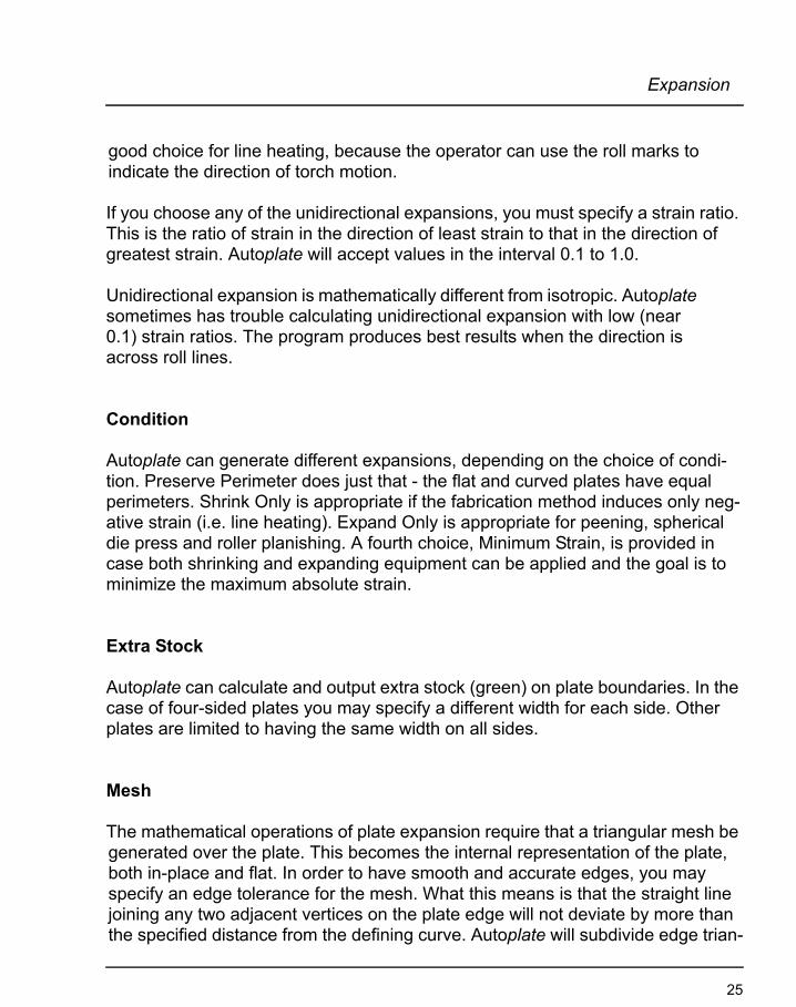
The Plates - Pin Jig menu choice produces the Plate Pin Jig dialogue. This allows you to set parameters for creation of pin jig data.
When you click OK, Autoplate cycles through the selected plates and generates pin placement for each. The result for any one plate may be seen in the Plate Viewer, and exported as a DXF layer.
28

Reports
Reports
Autoplate will generate both per-plate and summary reports. In both cases the included plates may be those selected or all plates in the project. A per-plate report contains the name, class, stock details, metric information and expansion results. A summary report is arranged by classification, indicating the number of plates, total weight, total area and total CG of plates in each class and for all classes.
The report is produced using the Autoship report editor, with all the editing and output capabilities of that system.
29
Chapter 3
Panels
A panel is a group of contiguous plates which are to be welded together. To this end, Autoplate will generate the data required to create a pin jig to hold the plates in their correct relation to one another.
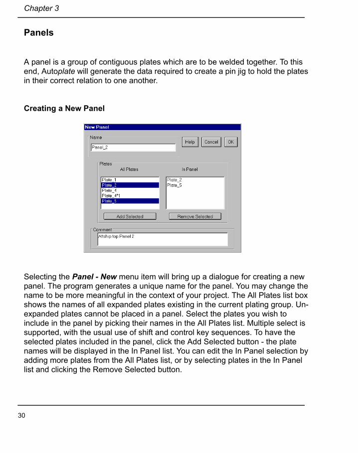
Creating a New Panel
Selecting the Panel - New menu item will bring up a dialogue for creating a new panel. The program generates a unique name for the panel. You may change the name to be more meaningful in the context of your project. The All Plates list box shows the names of all expanded plates existing in the current plating group. Un-expanded plates cannot be placed in a panel. Select the plates you wish to include in the panel by picking their names in the All Plates list. Multiple select is supported, with the usual use of shift and control key sequences. To have the selected plates included in the panel, click the Add Selected button - the plate names will be displayed in the In Panel list. You can edit the In Panel selection by adding more plates from the All Plates list, or by selecting plates in the In Panel list and clicking the Remove Selected button.
30
Reports
You may type a comment of arbitrary length into the Comment text box. This com-ment will be stored with the panel data and will appear whenever you edit the panel.
When selecting the plates to include in a panel, keep in mind that they should be at least partly contiguous. The program makes no attempt to enforce this, or even to prevent you from putting superimposed plates into a panel. In the latter case the program will produce meaningless results.
Selecting Panels
The second sub-menu item under Panel is Select. This brings up a dialogue in which you may select one or more panels. If just one panel is selected, the sec-ond (Edit) and third (Pin Jig) sub-menu items are enabled. The Edit item brings up the same dialogue as above, with the panel data filled in. You may edit this information, even adding and removing plates, and save the result. Multiple panel select is relevant to export as DXF (see below), where the program will export all selected panels.
Creating a Panel Pin Jig
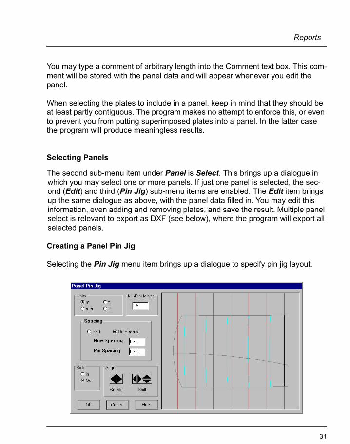
Selecting the Pin Jig menu item brings up a dialogue to specify pin jig layout.
31

Chapter 3
The picture box on the right displays a projected view of the panel with its plate boundaries visible as black lines. If a baseline is defined in the project, frame locations are displayed in cyan.
You can choose the units in which the minimum pin height and spacings are dis-played. In the Spacing frame there are option buttons to select between Grid and On Seams. These determine the type of pin layout created. In the former case, the pins lie on a regular grid, spaced according to the Row Spacing and Pin Spac-ing values. If you select this option, the red lines in the picture box, which repre-sent pin rows, will have small circles drawn at the pin locations. If you select On Seams, the pin location circles are not drawn. Pins will be placed on the row lines where they cross plate boundaries. If the span between any two pins exceeds the Pin Spacing value, extra pins will be inserted.
The Align controls allow you to place the pins as you wish. The Rotate spin control causes the row lines to rotate around the panel centre. The shift spin controls move the row lines. If the Grid spacing option is selected the pin locations are moved up and down by the right shift spin control.
When pin information is generated the layout may be chosen for the pins to be located either on the inside or outside of the hull. This is determined by the setting of the Side option.
32

Export
Export
Autoplate will generate per-plate drawings, per panel drawings and a shell expan-sion in DXF form. The dialogues for these drawings are accessed by clicking the appropriate sub menu item under Files - Export.
Plate DXF
When you have made your choice of options, Autoplate loops over all selected plates and generates, for each plate, a file for 2D output (if chosen) and another file for 3D output (if chosen). The default file names are created by pre-pending the characters "2dPLT_ " or "3dPLT_ " to the plate name. If a file of that name already exists in the destination directory you will be prompted to change the name or overwrite the file.
In both the 2D and 3D cases separate layers are generated for each option cho-sen. If any other option is chosen, the outline is included by default. If the Tem-plates option is included, the template layout lines and template shapes are placed on separate layers.
33

Chapter 3
The small boxes to the left of the check boxes are painted in the colour which will be used for the layer. If you click a colour box, a bar containing the available colours will appear. Clicking on one of the colour patches will change the layer colour to the one selected.
The view in 2D output is from the inside of the hull (provided the surface is ori-ented with normal vectors pointing outward). If, when you created the plate you chose Twin across center plane, drawings will be produced for the plates on both sides of the hull.
If Curves is chosen (either 2D or 3D), the program draws all curves which are embedded or projected on the surface patch covered by the plate. If the Offsets option is chosen, the program draws x and y Cartesian axes and shows the coor-dinates of points with respect to these axes.
Strain contours and thickness contours may be used to guide fabrication. The former indicates the magnitude of strain to be induced at each point on the plate while the latter can be used to monitor the fabrication process.
The 3D output represents the in-place plate. Choosing Mesh in the 3D output pro-duces a PFACE entity representation.
The units options allow you to choose the units in which the drawings are pro-duced.
34

Export
Panel DXF
Having assigned plates to a panel (Panel - New menu item) and defined the lay-out of a pin jig for the panel (Panel - Pin Jig menu item), you can export the resulting layout to a DXF file. The program loops over all selected panels (Panel - Select menu item) and produces one file per panel. The file name is composed of the panel name appended to "Panel_". Colour choices for layers are selected as described in the previous section.
35

Chapter 3
Shell Expansion
Making a choice of options and clicking OK will result in generation of a DXF file containing a shell expansion of the current plate project. If no option is chosen, only the expansion outline will be produced. A separate layer will be created for each option.
The program will optionally refine each surface and curve to a specified tolerance before performing the expansion calculations, which are based on table values.
The colour patches to the left of each check box indicate the colour which will be used for that layer. You can change any colour by clicking on the patch and choosing a colour from the palette presented.
36

Invalidation and Regeneration of Plates
Invalidation and Regeneration of PlatesAt any time, each plate is in one of four states: invalid un-expanded (iu), valid un-expanded (vu), invalid expanded (ie) or valid expanded (ve). A valid plate can be marked invalid for several reasons:
• Its classification has been changed,
• The surface on which the plate lies, or the surface used to generate the poly-object on which the plate lies, has been modified since the plate was expanded,
• Any of the bounding curves has been modified since the plate was expanded.
Checks for the last two situations are performed every time a project is loaded. If any plate is found to be invalid at this time, a message is displayed saying that at least one plate is invalid. A check for invalidation is also performed each time a curve is edited in Autoplate.
You can determine what state a plate is in by bringing up the plate selection dia-logue and selecting the class for the desired plate. The first two columns in the list box contain "iu", "vu", "ie" or "ve".
Selecting the Regenerate menu item causes Autoplate to loop over all plates in the project, performing regeneration on any which has an invalid expansion. If the plate has never been expanded, its boundary and mesh only are regenerated. If it has been expanded, the expansion is recalculated, using the original expansion parameters.
If any boundary curve defining a plate or the surface or polyobject on which the plate resides has been deleted from the PRx or PLA file, that plate will also be deleted.
37
Chapter 3
Plate Deletion
You may delete one or more plates by selecting them and then choosing Delete from the Edit menu or by pressing the Delete key. Delete works only in select mode.
Switching between Autoship and Autoplate
It is possible to run these programs simultaneously. Before switching from Auto-plate to Autoship, save the plate project. To switch from Autoship to Autoplate, save the Autoship project, then reload the Autoplate project; it will read in the new version of the PRx file.
Beware of making changes to the Autoship project which affect the plate project. Editing curves, surfaces and polyobjects which are used in Autoplate may invali-date plates. Any invalid plates should be regenerated. Deleting any such object will cause the dependent plates to be deleted when regeneration is performed.
References
Lamb, Thomas. 1994. "Report on Limitations of Computerized Lofting for Shell Plate Development", The Society of Naval Architects and Marine Engineers, Ship Production Committee.
38
Tutorial
Chapter 4
Tutorial
Preliminary Considerations
In order to produce an expansion of a surface patch, Autoplate requires a sur-face definition. Autoplate does not have the capability to produce a surface def-inition and relies on input from Autoship. The form of this input is an Autoship project file - PR2 for Autoship 6, PR3 for Autoship 7. Autoplate uses this file, but to ensure data integrity, does not make changes to it. Instead, Autoplate stores its information in a file having the extension PLA. Hence an Autoplate project consists of two files: the PRx and the PLA; the PLA file is of no use with-out the appropriate PRx file.
The definition produced in Autoship consists of various curves, surfaces and poly-objects. Autoplate requires that the entities (surfaces and polyobjects) defining the region to be plated be collected together in a Group. For each polyobject to be used in a plating group the original surface must exist in the Autoship project.
Since there is no facility in Autoplate for creating a surface or polyobject; the sur-face definition must be completed in Autoship before turning to Autoplate.
Operation of Autoplate consists of laying out curves on the surface of the model, choosing appropriate curves as plate boundaries and then having Autoplate cre-ate and expand a plate over the enclosed area.The intent of this tutorial is to guide you through the entire process of starting a new Autoplate project (using an Autoship project supplied with the Autoplate installation) and producing the information to cut and form the various type of shell plates usually encountered in a ship constructed of metal. Additionally, insight into the tools which help the operator optimize plate production is provided.
It is assumed that you have a basic understanding of the principles, operation and building blocks of the Autoship program.
39

Chapter 4
Starting a New Autoplate Project
When Autoplate was installed on your system, a tutorial folder was created and a file named APTUT.PR3 was copied to it. This model is composed of several curves, six surfaces, four polyobjects and two groups.
The group "Aft Plating Group" consists of:
• polyobject Trimmed Hull Aft Lower• polyobject Trimmed Stern Bulb • surface Hull Aft Upper
The group "Fwd Plating Group" consists of:
• polyobject Trimmed Hull Fwd Lower • polyobject Trimmed Fwd Bulb • surface Hull Fwd Upper
These are the surface definitions we will be using.
We suggest that a separate directory be created for each new vessel, or portion of a vessel to be plated and all the work for that project be stored in that directory. For the purposes of this tutorial, we will use the TUTORIAL directory found under the AUTOPLATE directory.
The first operation necessary to start a new plating project is to bring the Autoship project into Autoplate. After you have started Autoplate, select the File - New menu item to begin a new project. The Open Autoship Project File dialogue will appear. This is where you indicate which Autoship project you will be using for your Autoplate project. Pick the file APTUT.PR3 found in the TUTORIAL directory found under the AUTOPLATE directory.
After the project is loaded, the Autoplate screen will probably be blank. This is because, by default, nothing has been selected to be shown.
40
Starting a New Autoplate Project
In the top bar, click the Groups button to show the groups in the project.
Notice that the button changes state. Now you should see the outline of the tuto-rial model on screen. If your screen is not showing all four views, click the Four
View button at the bottom of the screen. Select the Settings menu and pick the Preferences item, click the Coordinate System button in the Prefer-ences dialogue and select the Naval/Aircraft US radio button. Click OK to exit the Coordinate System dialogue, and then OK to exit the Preferences dialogue.
Next, we have to indicate to Autoplate which portion of the hull, or group, we will be working with.
Click the Plate menu and pick the Group item. In the Select Group For Plating dialogue that opens, pick Fwd Plating Group and Click OK.
Now to visualize the portion we wish to work on and enable Autoplate to deal with
it, click the Show Plate Group button in the top toolbar. Notice that the but-ton changes state. On the screen, you will see that now only the forward half of the vessel is shown.
When the Show Plate Group button is on, only the surfaces and polyobjects in the plating group, plus any curves that are embedded or projected onto these objects in the plating group, will be visible.
41
Chapter 4
Defining Plate Stock
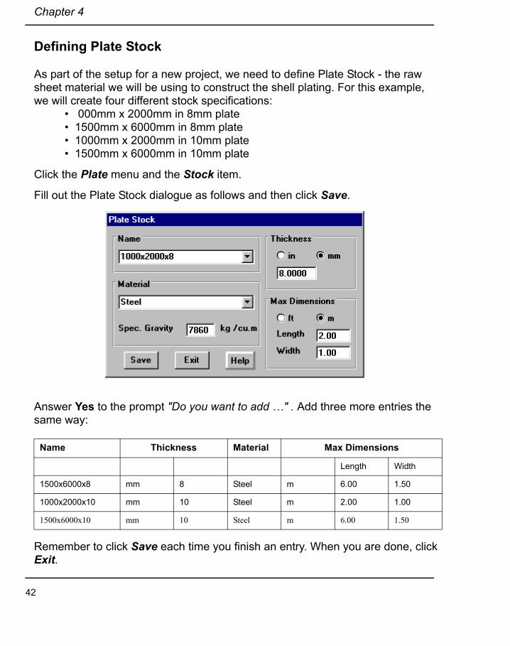
As part of the setup for a new project, we need to define Plate Stock - the raw sheet material we will be using to construct the shell plating. For this example, we will create four different stock specifications:
• 000mm x 2000mm in 8mm plate• 1500mm x 6000mm in 8mm plate• 1000mm x 2000mm in 10mm plate• 1500mm x 6000mm in 10mm plate
Click the Plate menu and the Stock item.
Fill out the Plate Stock dialogue as follows and then click Save.
Answer Yes to the prompt "Do you want to add …" . Add three more entries the same way:
Remember to click Save each time you finish an entry. When you are done, click Exit.
Name Thickness Material Max Dimensions
Length Width
1500x6000x8 mm 8 Steel m 6.00 1.50
1000x2000x10 mm 10 Steel m 2.00 1.00
1500x6000x10 mm 10 Steel m 6.00 1.50
42
Plate Classification
Plate Classification
Next, we will set up a Plate Classification system.
Plate Classification is a categorization scheme intended to help the designer organize the various plates into meaningful groups. The architecture of the organization is entirely open - it may be laid out in any manner that suits the pur-pose. For instance, you could choose to categorize your plates based upon sup-plier or the region of the hull to be plated or the date of forming. Creating a Plate Class scheme is not required but can be very useful.
Click the Plate menu and the Class item to bring up the Plate Classifica-tion dialogue. This is divided into two sections: the left half is used to define the classification tree; the right half is used to control where plates fit into the classification tree.
In the Plate Classification dialogue, under Class Tree, Fwd Plating Group will appear highlighted. This is the entire tree structure of the classification system so far. We want to add some branches and leaves to the existing tree.
Suppose for our vessel that we have two different shops, Shop A and Shop B, available to cut and form our plates. Further, the two shops have different form-ing capabilities, and Shop B can only handle the smaller stock.
With Fwd Plating Group selected, click the New Level button. This will add another category below the Fwd Plating group. A dialogue with Class1 high-lighted will appear, change Class1 to Shop A and Click OK. Now our tree con-sists of Fwd Plating Group with a sub-category named Shop A.
Let's add some leaves, 8mm and 10mm, under Shop A. With Shop A selected, click the New Level button again. Change Class2 into 8mm.
Now create category 10mm at the same level as 8mm: with 8mm selected click the Add At Level button. Change Class3 into 10mm.
Now we want to add Shop B, also with 8mm and 10mm: With Shop A selected, click the Add At Level button and change Class2 into Shop B.
43
Chapter 4
With Shop B selected, click New Level, change Class2 to 8mm. With 8mm selected, click Add At Level and change Class3 to 10mm.Further, for this example, we want to associate a particular class with a particu-lar type of stock. Since Shop B can only work with the smaller stock, lets associ-ate the 1000mm x 2000mm plates with Shop B:
Click the 8mm category under Shop B and then in the Stock box, pick 1000x2000x8. Answer Yes to the "Are you sure …" prompt. Then, still for Shop B, click the 10mm category and for Stock, pick 1000x2000x10.
Now, do the same for Shop A using the 1500x6000 stock sizes.
Later, when we are defining plates, they may be assigned to any of the terminal categories, or leaves.
Click Exit when you are done creating your classification system.
44

Setting Up a Baseline
Setting Up a Baseline
In order to help us lay out butts to be offset from frames, we can utilize a func-tion in Autoplate which defines frame locations. The same function is available in Autoship and, if used there, the information will be passed through to Auto-plate.
Click the Settings menu and pick the Preferences item and in the Preferences dialogue, click the Baseline button.
For the vessel we are using in this tutorial, the aft extent is at L = 2.5A (A for Aft of the origin) and the forward extent is at L = 137.5F (F for Forward of the ori-gin). The AP is at 4F, the FP is at 130F. Suppose we want the following frame spacing:
• 800mm for aft of the AP• 700mm from the AP to the FP (or as close as possible)• 800mm ahead of that
In the Baseline dialogue, under Group for First Location enter 2.5A; for Last Location enter 4F, for Separation enter .8 and then click the Insert Group but-ton. In the Frame box, note that frame 9 is at 4.0F while frame 8 is at 3.9F. Since we want a frame to coincide with the AP at 4.0F, we need to move the frames forward by .1m: change First Location to 2.4A, Last Location to 4F and click the Insert Group.
Note that now frame 1 is at 2.5A and frame 2 is at 2.4A. We don't need the frame at 2.5A, so in the Frame box, click the Frame 1 line and then click the Delete button.
Suppose we wanted frame 0 to be located at the AP: In the First Frame Number box, type -8 and click the Apply button. In the Frame box, the frame numbers are now re-organized to match the new input.
Continuing with the other two sets: For First Location, type 4F, for Last Location type 130F, for Separation type .7 and click Insert Group.
45

Chapter 4
If you scroll to the bottom of the Frame list, you will see that frame 180 is at 130F.
The final set: For First Location, type 130F, for Last Location type 138F, for Sep-aration type .8 and click Insert Group. Now scroll to the bottom of the frame list, the last frame is at 138F and the second to last is at 137.2F. We don't need the frame at 138F, so delete it.
Click OK to return to the Preferences dialogue. If the checkbox beside Display Baseline is not checked, do so now. Click OK to return to the main screen. The baseline should show in the plan and profile views.
Now we have finished with the setup necessary for a new project. Before we carry on to produce some plates, save this Autoplate project.
46

Laying Out Seams and Butts
Laying Out Seams and ButtsAs a first example, we will lay out some plates forward of midships on the bot-tom of the hull. Suppose that in the forward part of the vessel the butts are to be 100mm forward of frame locations. Working forward from midships, we expect to be able to use the larger of the plate stock we have defined. Midships is at 55F, the large plates are 6m, so we need a butt at around 100mm forward of the frame just aft of 61F. The baseline definition shows frame 81at 60.7F; let's posi-tion a butt at 60.8F.
Expecting that butts will be staggered between adjacent strakes, we need to position a butt somewhere between 55F and 60.8F. From the Frame List, frame 77 is at 57.9F, so let's put a butt at 58F. Then, 6m fwd of 58F is 64F and frame 85 is at 63.5F, so our next butt will be at 63.6F.
To define plate boundaries, i.e. a butt, we need to use either an embedded or a projected curve. An easy way to define each of these three butts is to create a simple straight curve running transversely and then project it up onto the hull to produce a projected curve in the correct location. Click the Create button and then the Curve button. In the Create Curve dia-logue, with the Free tab selected, complete the dialogue as follows.
Click OK when you are done.
47

Chapter 4
Then we can create the butt: Click Create - Curve; this time, select the Projected tab, enter the following data and Click OK when you are done.
You may find it easier to visualize these curves if you turn off the baseline: Settings - Preferences - Display Baseline checkbox.
We will create Butt 2F at L = 60.8F in the same manner.
The template curve: click Create then the Curve button and input the fol-lowing:
Name Butt 1F
Tab Projected
Type Type 2
Projection Top
Source Curves Butt 1F Template
Host PolyObjectTrimmed Hull Fwd Lower
Acceptable Tolerance .001
Name Butt 2F template
Tab Free
Control Pts 2Free
End 1 L = 60.8F
End 2 L = 60.8F T = 13
48

Laying Out Seams and Butts
The Butt Curve:
Click Create - Curve and input the following:
Create Butt 3F at L = 63.5F the same way:
The Template Curve:
The Butt Curve:
Name Butt 2FTab ProjectedType Type 2Projection TopSource Curve Butt 2F templateHost Polyobject
Trimmed Hull Fwd LowerAcceptable Tolerance .001
Name Butt 3F templateTab FreeControl Pts 2End 1 L = 63.5FEnd 2 L = 63.5F
T = 13
Name Butt 3FTab ProjectedType Type 2Projection Top.Source Curve Butt 3F templateHost Polyobject
Trimmed Hull Fwd LowerAcceptable Tolerance .001
49
Chapter 4
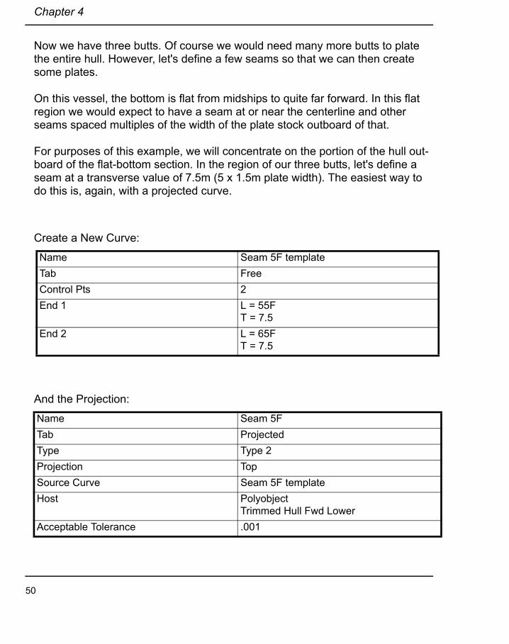
Now we have three butts. Of course we would need many more butts to plate the entire hull. However, let's define a few seams so that we can then create some plates.
On this vessel, the bottom is flat from midships to quite far forward. In this flat region we would expect to have a seam at or near the centerline and other seams spaced multiples of the width of the plate stock outboard of that.
For purposes of this example, we will concentrate on the portion of the hull out-board of the flat-bottom section. In the region of our three butts, let's define a seam at a transverse value of 7.5m (5 x 1.5m plate width). The easiest way to do this is, again, with a projected curve.
Create a New Curve:
And the Projection:
Name Seam 5F templateTab FreeControl Pts 2End 1 L = 55F
T = 7.5End 2 L = 65F
T = 7.5
Name Seam 5FTab ProjectedType Type 2Projection TopSource Curve Seam 5F templateHost Polyobject
Trimmed Hull Fwd LowerAcceptable Tolerance .001
50

Laying Out Seams and Butts
For the next seam, we can use a special curve type named Geodesic Offset to put another curve at a specific distance, measured along the surface, away from Seam 5. To ensure that the resulting plate fits onto plate stock of width 1.5m let's make the offset distance 1.45 m.
Create another curve, as follows, using the Geod. Off. Tab:
51
Chapter 4
Defining a Plate
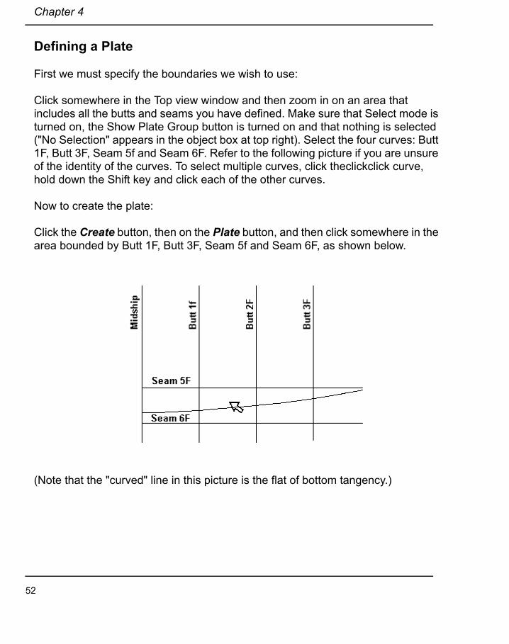
First we must specify the boundaries we wish to use:
Click somewhere in the Top view window and then zoom in on an area that includes all the butts and seams you have defined. Make sure that Select mode is turned on, the Show Plate Group button is turned on and that nothing is selected ("No Selection" appears in the object box at top right). Select the four curves: Butt 1F, Butt 3F, Seam 5f and Seam 6F. Refer to the following picture if you are unsure of the identity of the curves. To select multiple curves, click theclickclick curve, hold down the Shift key and click each of the other curves.
Now to create the plate:
Click the Create button, then on the Plate button, and then click somewhere in the area bounded by Butt 1F, Butt 3F, Seam 5f and Seam 6F, as shown below.
(Note that the "curved" line in this picture is the flat of bottom tangency.)
52
Defining a Plate
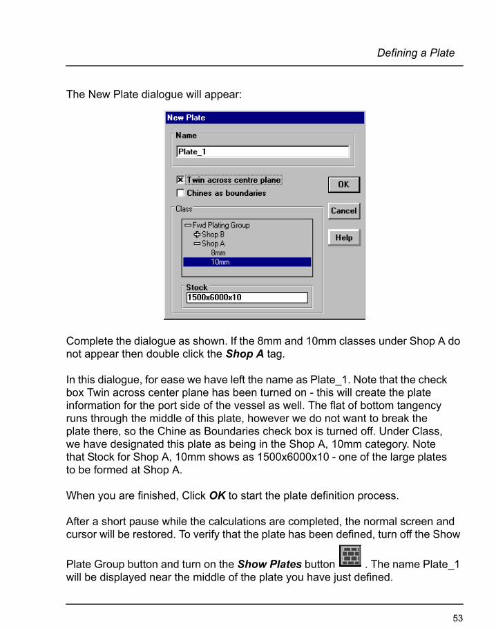
The New Plate dialogue will appear:
Complete the dialogue as shown. If the 8mm and 10mm classes under Shop A do not appear then double click the Shop A tag.
In this dialogue, for ease we have left the name as Plate_1. Note that the check box Twin across center plane has been turned on - this will create the plate information for the port side of the vessel as well. The flat of bottom tangency runs through the middle of this plate, however we do not want to break the plate there, so the Chine as Boundaries check box is turned off. Under Class, we have designated this plate as being in the Shop A, 10mm category. Note that Stock for Shop A, 10mm shows as 1500x6000x10 - one of the large plates to be formed at Shop A.
When you are finished, Click OK to start the plate definition process.
After a short pause while the calculations are completed, the normal screen and cursor will be restored. To verify that the plate has been defined, turn off the Show
Plate Group button and turn on the Show Plates button . The name Plate_1 will be displayed near the middle of the plate you have just defined.
53
Chapter 4
At this point in time, we have defined one plate, however, it has not been expanded and so there is not yet any information with which to cut and form the plate.
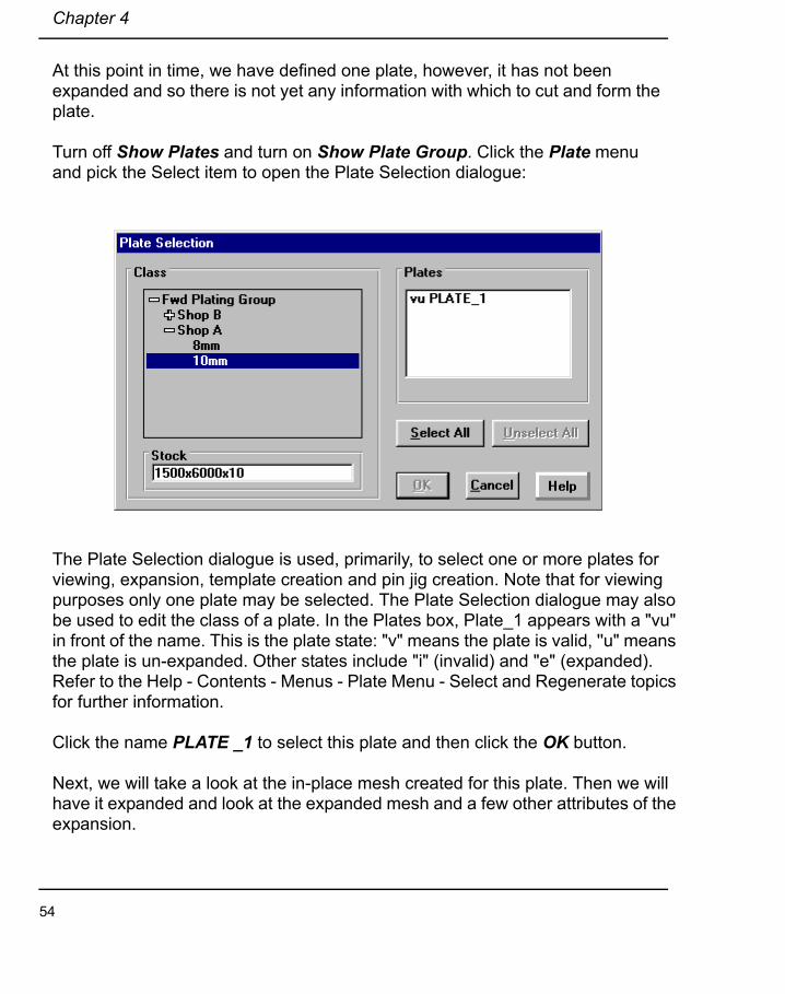
Turn off Show Plates and turn on Show Plate Group. Click the Plate menu and pick the Select item to open the Plate Selection dialogue:
The Plate Selection dialogue is used, primarily, to select one or more plates for viewing, expansion, template creation and pin jig creation. Note that for viewing purposes only one plate may be selected. The Plate Selection dialogue may also be used to edit the class of a plate. In the Plates box, Plate_1 appears with a "vu" in front of the name. This is the plate state: "v" means the plate is valid, ''u" means the plate is un-expanded. Other states include "i" (invalid) and "e" (expanded). Refer to the Help - Contents - Menus - Plate Menu - Select and Regenerate topics for further information.
Click the name PLATE _1 to select this plate and then click the OK button.
Next, we will take a look at the in-place mesh created for this plate. Then we will have it expanded and look at the expanded mesh and a few other attributes of the expansion.
54

Defining a Plate
Click Plate - View:
The View dialogue is used to see various attributes of a plate. In this case, because this plate has not been expanded, only the radio buttons in the left col-umn under the Image tab are available.
It is good practice to view the in-place mesh of a plate before expanding it. In some rare cases the program produces a faulty mesh and that will prevent proper expansion of the plate. Such problems can often be detected by viewing the mesh.
Try a few of the other options to see the results and then click Exit when you are done.
55
Chapter 4
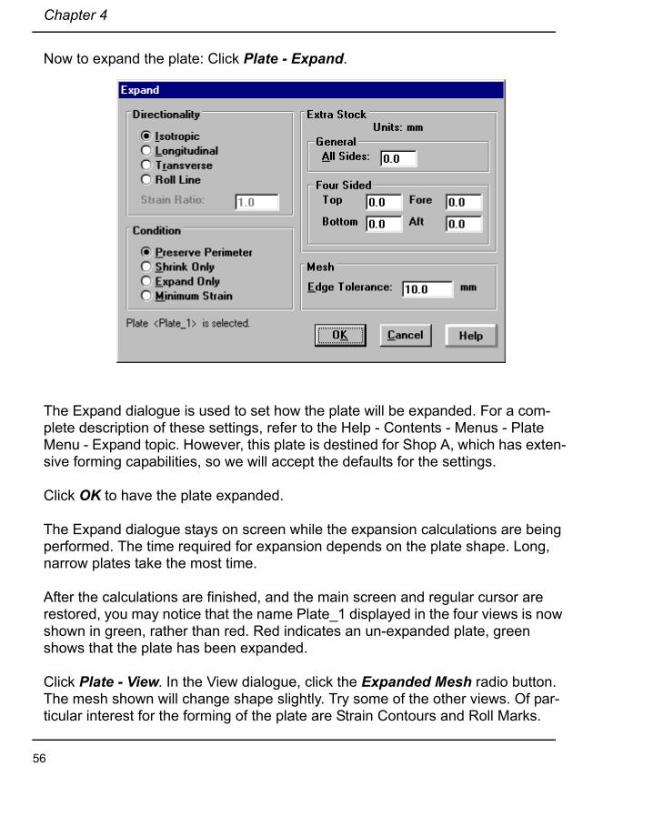
Now to expand the plate: Click Plate - Expand.
The Expand dialogue is used to set how the plate will be expanded. For a com-plete description of these settings, refer to the Help - Contents - Menus - Plate Menu - Expand topic. However, this plate is destined for Shop A, which has exten-sive forming capabilities, so we will accept the defaults for the settings.
Click OK to have the plate expanded.
The Expand dialogue stays on screen while the expansion calculations are being performed. The time required for expansion depends on the plate shape. Long, narrow plates take the most time.
After the calculations are finished, and the main screen and regular cursor are restored, you may notice that the name Plate_1 displayed in the four views is now shown in green, rather than red. Red indicates an un-expanded plate, green shows that the plate has been expanded.
Click Plate - View. In the View dialogue, click the Expanded Mesh radio button. The mesh shown will change shape slightly. Try some of the other views. Of par-ticular interest for the forming of the plate are Strain Contours and Roll Marks.
56

Defining a Plate
Strain is the proportional change in linear dimension of material under applied forces. Autoplate calculates the strain which must be induced in flat plate stock to give it the shape of the hull patch it is meant to cover. The strain is presented as contours. The cyan coloured contours show the amount by which the plate mate-rial must be stretched while the yellow contours show the amount of shrinking required. When the maximum strain, displayed below the strain map, is smaller than about 1/10 % one can assume that the plate will probably fit on the hull with-out stretching or shrinking beforehand.
When a plate is worked to stretch or shrink it, the thickness is decreased or increased, respectively. The program calculates this effect and the results may be viewed by clicking the Thickness Contours radio button.
Note that Template and Pin Jig information are not available because you have not yet requested their calculation.
Congratulations! You have successfully defined and expanded your first shell plate.
Since that plate was so successful, lets try the half-plate just aft: Make sure that the Show Plate Group button is turned on. Select Butt1F, Seam 5F and Seam 6F. Click the Create mode button, the Plate button and then somewhere between Butt1F, Seam 5F and Seam 6F and the aft end of polyobject Trimmed Hull Fwd Lower.
57

Chapter 4
At the New Plate dialogue, leave the name at Plate_2, check Twin across center plane and for Class, pick Shop A, 10mm. Click OK when you are done.
The resulting calculation may take a some time. When the main screen is restored, turn off Show Plate Group and turn on Show Plates.
The name Plate_2 will appear, however, it is not in the correct location - some-thing has gone wrong in the definition. If you switch to 4 views, you may see that Plate_2 extends from Seam 5F to the top of the polyobject Trimmed Hull Fwd Lower and from the aft end of Trimmed Hull Fwd Lower to Butt 1F - completely ignoring Seam 6F.
The problem is that Seam 6F is a Geodesic Offset and one of the properties of Geodesic offsets is that they are offset at right angles to the original. Due to the shape of Trimmed Hull Fwd Lower, which narrows towards the forward end, an outboard offset perpendicular to Seam 5F shifts forward, thus the aft end of Seam 6F is further forward than the aft end of Seam 5f - and the aft end of Trimmed Hull Fwd Lower. Consequently, because Seam 6F does not connect with the aft edge of Trimmed Hull Fwd Lower it does not, in conjunction with the other curves selected, constitute a valid plate boundary in that area.
Geodesic Offset curves are not themselves editable. However, you can match that curve with a regular embedded curve and then edit the embedded curve to move its aft end to the aft edge of the polyobject.
Create a New Curve:
Name Seam 6FATab MatchType EmbeddedAcceptable Tolerance .005Source Curve Seam 6F
58

Defining a Plate
Now we need to make sure Seam 6FA runs all the way aft to the edge of Trimmed Hull Fwd Lower:
Click the Select mode button and then the Edit mode button .
In the top view, zoom in so that you can see the aft end of curve Seam 6FA.
The cross hairs should highlight the vertex at the aft end of the curve. If they are not, use the F3 and F4 keys to shift the cursor until it is.Press the left arrow key on the keyboard once or twice to move the cross hairs, and the vertex, further aft. Press the Enter key to register this change. The cross hairs and the vertex should jump to the aft edge of Trimmed Hull Fwd Lower.
Curve Seam 6FA should be a valid plate boundary and so we will use Seam 6FA rather than Seam 6F. Select Edit - Attributes and turn off the visibility of Seam 6F.
Let's delete Plate_2 and re-define another plate: Go to Plate - Select and pick Plate_2. Click OK. Click the Select mode button and then the Delete
button.
At the Delete Selected Objects dialogue, pick Selected Plates Only and Click OK.
Make sure that the Show Plate Group button is turned on. Select Seam 6FA, Butt 1F and Seam 5F by clicking on them in the Top view. Now, just as before, click the Create mode button, the Plate button and then somewhere between Butt1F, Seam 5F and Seam 6FA and the aft end of polyobject Trimmed Hull Fwd Lower. At the New Plate dialogue, keep the name Plate_2, check Twin across center plane and for Class, pick Shop A, 10mm. Click OK when you are done.
When the main screen is restored, turn off Show Plate Group and turn on Show Plates. The name Plate_2 will appear, this time in the correct location.
59

Chapter 4
Now check the mesh to make sure the definition is correct: because Plate_2 was just created, it is also currently selected, so we can go straight to Plate - View without having to select a plate first.
If the mesh is regular then expand the plate: click Exit and then Plate - Expand. Note in the bottom left of the Expand dialogue Plate_2 is listed as the current plate. Again, accept the defaults for this expansion as this plate is destined for the shop which has more elaborate forming capabilities.
After the plate has been expanded, go to View. By toggling repeatedly between In Place Mesh and Expanded Mesh you will see that the plate has not changed shape significantly. Roll Mark shows an interesting pattern: remember this plate has a flat-of-bottom tangency running lengthwise through the middle - and the roll marks show this attribute. Looking at Strain Contours, notice from the strain val-ues shown at the bottom of the dialogue that this plate requires no shrinking and that the amount of expansion is negligible.
60

Defining Templates
Defining Templates
Templates are very much as the name implies - shapes that are cut out of a pla-nar material, such as plywood, and used as a guide during the plate forming process by holding the cut edge against the plate at certain locations. In order to indicate how the templates fit on the plate, template markings are provided at user-specified locations and the template is created the same width as the formed plate so that each end of the template fits to an edge of the plate. Fur-ther, each template has a handle - a straight reference line which is used to align the group of templates. While forming the plate, the templates are cor-rectly oriented when the templates are positioned at their proper locations, all of the handles are lined up in a common sight plane and the handle tops are lined up. This is illustrated below. Note that the template planes are normal to the sight plane.
61

Chapter 4
With plate_2 selected, click Plate - Templates.
The Templates dialogue is used for laying out the position and orientation of templates and their handles. In this dialogue:
Sight Line refers to the orientation of the sight plane.
• Best Fit positions the plane along the major axis, or length of the plate. • Horizontal positions the plane horizontally as depicted in the View window. • Vertical positions the plane vertically as depicted in the View window. • Normal to Frames positions the plane lengthwise, normal to the frames.
Arrangement sets the interval between adjacent templates.
• Spacing is used to input an exact measurement. • Number partitions the length of the plate into the given number of intervals. • At Frames positions one template at each frame. • Min Height determines the length of the shortest template handle.
Since we have specified frame locations, in the Sight Line group pick Normal to Frames and in the Arrangement group pick At Frames. Leave Min Height at 1m. Click OK and then go back to Plate - View.
Now when you click the Template layout option, the expanded plate outline will have several coloured lines superimposed. These are the locations of the tem-plates we specified. The template locations can be included in an exported DXF.
Click the Templates option to see the shape of the various templates. Note that the template shapes are colour-keyed with the locations just seen with the layout option. The straight lines with the right-angle hook at the upper end are the tem-plate handles. The template shapes are exportable via DXF.
The results of template calculations are stored in the plate file.
62
Defining Pin Jig Settings
Defining Pin Jig Settings
A pin jig is another optional aid to plate forming. To calculate jig settings, select one or more expanded plates and then click the Plate - Pin Jig menu item. In the Plate Pin Jig dialogue, set the parameters as follows:
• Min Pin Height is used to tell Autoplate the lowest setting that your pin jig can accommodate.
• The Spacing group is used to lay out the grid of pins; X corresponds to the longitudinal direction, Y is transverse.
• The Units group sets the units used for pin jig output.
Under Spacing, set X to .5 and leave the other settings as they are. Return to the View window and select Pin Jigs. Because of the shape of the plate, the upper left pin does not fit on the plate, and so is not shown. Note that the spac-ing of the pins is less in the X direction (longitudinally) than it is in the Y direction (transverse).
63

Chapter 4
Defining Plates on the Stern Bulb
First we need to alert Autoplate that we now want to work with the Aft Plating Group: Go to Plate - Group and select Aft Plating Group. If the Plate - Group item is grayed out, click the Select mode button. Click the Show Plate Group but-ton to verify that the proper part of the hull is selected.
Before we can do any plating on the aft portion of the hull, we must specify some classes of plates. If we assume we will be working with the same shops as for the forward portion, then the classification scheme will be the same. However, let's also suppose we have access to some 2000mm by 6000mm by 10mm stock for this part of the hull. Create a new stock called 2000x6000x10. In the Classification dialogue, set up a class with this stock in Shop A in the Aft Plating Group.
Because of the high degree of curvature, the plates will have to be more wedge shaped on the stern bulb than elsewhere on the vessel
Let's start by dividing the bulb polyobject in half length-wise with an embedded curve:
In Side view, zoom in on the stern bulb area. Make sure the Show Plating Group button is turned on.
Make a new plate: click the Create mode button, the Plate button and then on the part of the stern bulb above the curve just created. In the New Plate dia-logue, for Class pick Aft Plating Group - Shop A - 10mm.
Name Stern Bulb Seam 1Tab EmbeddedHost Polyobject
Trimmed Stern BulbEnd 1 r = 0
c = .5End 2 r = 1
c = .5
64

Defining Plates on the Stern Bulb
Verify that the correct plate has been created by turning off Show Plate Groups and turning on Show Plates.
Now when you go to expand this plate you should receive the message "One or more plates is larger than the specified stock." This means that the area to be plated will have to be reduced in size.
This is easiest accomplished by running a butt vertically to cut the bulb in half. And the easiest way to create this butt is with a projected curve.
Create a New Curve:
And then its Projection:
Name Stern Bulb Butt 1 templateTab FreeControl Pts 2End 1 L = 4.1
V = 4.5End 2 L = 4.1
Name Stern Bulb Butt 1Tab ProjectedType Type 2Projection SideSource Curve Stern Bulb Butt 1 templateHost Polyobject
Trimmed Stern BulbAcceptable Tol .005
65
Chapter 4
Delete the last plate made and then, using the projected curve just created, define a new plate in the upper aft portion of the stern bulb.
Remember to select the two boundary curves, Stern Bulb Seam 1 and Stern Bulb Butt 1, before creating the plate. Verify that the plate is where you expect it to be by turning off the Show Plate Group button and turning on the Show Plates button.
Now, expand this plate, using the default settings.
Next, view the plate. Try to compare the un-expanded mesh to the expanded mesh. Because this plate has a high degree of curvature, we should pay special attention to the forming details: take a look at the Thickness Contours. Note the values at the bottom of the dialogue. Thinned Min and Thickened Max indicate that, for the formation process chosen, this plate must be made both thicker in some regions and thinner in others. This is also revealed in the Strain Contours, where both stretching and shrinking are indicated. Some shops cannot perform both operations.
Assuming that only stretching is available do the following: select Plate - Expand, set condition to Expand Only and Click OK.
When the plate expansion is finished, view the Thickness Contours again. This time there is no thickening of the plate, only thinning.
Now let's plate the rest of the stern bulb, starting with the forward top section:
In Select mode, select curves Stern Bulb Seam 1 and Stern Bulb Butt 1. Then in Create mode, click the Plate button and in the side view click somewhere above and forward of the intersection of Stern Bulb Seam 1 and Stern Bulb Butt 1. In the New Plate dialogue, keep name as Plate_4, check Twin across centerplane, select Shop A - 8mm and Click OK. Again, verify the plate definition: turn off Show Plate Group and turn on Show Plates.
If the definition is correct, select the plate and expand it. Like Plate_3, set Condi-tion to Expand Only. Check the results in Plate - View.
Lets create and expand the bottom two plates a slightly different way: Stern Bulb Seam 1 and Stern Bulb Butt 1 should still be selected. Create a new plate directly
66
Defining Plates on the Stern Bulb
below Plate_3. When that definition is finished, create another new plate directly below Plate_4. Verify the definitions.
Now choose Plate - Select. Plate_6 should be selected. Hold down the shift key and click Plate_5. Now both Plate_5 and Plate_6 are selected. Go to Plate - Expand. Note that "Two plates are selected" appears at the bottom left of the Expand dialogue. Set Condition to Expand Only and Click OK to expand both of these plates.
Again, we get the message that one of the plates is larger than the available stock. Since two plates are selected, we need to find which plate is too large.
Go to Plate - Select and pick Plate_5. Go to Plate - View and pick the Data tab. The bottom entry on the right side shows that the plate is oversized for the stock. The Size values on the left show us the overall plate size. Comparing that to the Stock Name at the top left, we can see that the plate is too wide for the stock. Repeat this same procedure for Plate_6. Evidently, both plates are too wide.
We have just seen that these two plates are too wide, so we must split them. Obviously, the easiest approach would be to create another seam.
Delete the two plates Plate_5 and Plate_6: from Plate - Select, pick Plate_5, hold down the Shift key and pick Plate_6. Click OK. In Select mode, click the Delete button. In the Delete Selected Objects, with Selected Plates Only turned on, click OK.
Create a New Curve with the Following Settings:Name Stern Bulb Seam 2Tab Surf Row/ColType EmbeddedAxis ColumnParameter 0.75Host Polyobject: Trimmed Stern Bulb
67

Chapter 4
With the boundary curves Stern Bulb Seam 1, Stern Bulb Seam 2 and Stern Bulb Butt 1 selected, create Plate_5 as the aft, mid-height portion of the bulb. Create Plate_6 as the forward, mid-height portion, Plate_7 as the lowest aft portion and Plate_8 as the lowest forward portion. You may have to zoom in close to point at the location of Plate_7 and Plate_8. Verify the definitions. If Plate_7 is hard to visualize, double click in a black portion of the screen to de-select the curves and then select Plate_7 from Plate - Select.
Now expand these four plates, again using Expand Only. You will find that they all fit on the stock specified.
68

Defining Plates on the Bow Flare
Defining Plates on the Bow Flare
Now let's make some plates on the highly flared section at the upper forward por-tion of Hull Fwd Lower. First, under Plate - Group select Fwd Plating Group.
Lets work down from the knuckle line and out from the centerline. In order to make plates of constant width we will lay out the seams as geodesic offset curves. To start this process we create an embedded curve along the top of the lower forward hull:
Create three geodesic offset curves:
Shop B will be forming these plates. Remember, they can handle 1m x 2m stock. Lets set the geodesic spacing at 950mm.
Name Fwd Knuckle Line Tab EmbeddedHost Polyobject
Trimmed Hull Fwd LowerEnd 1 r = 1
c = 0End 2 r = 1
c = .5
Name Seam A
Tab Geod. Off.
Offset LeftDistance = .95
Source Curve Fwd Knuckle Line
Host PolyobjectTrimmed Hull Fwd Lower
69
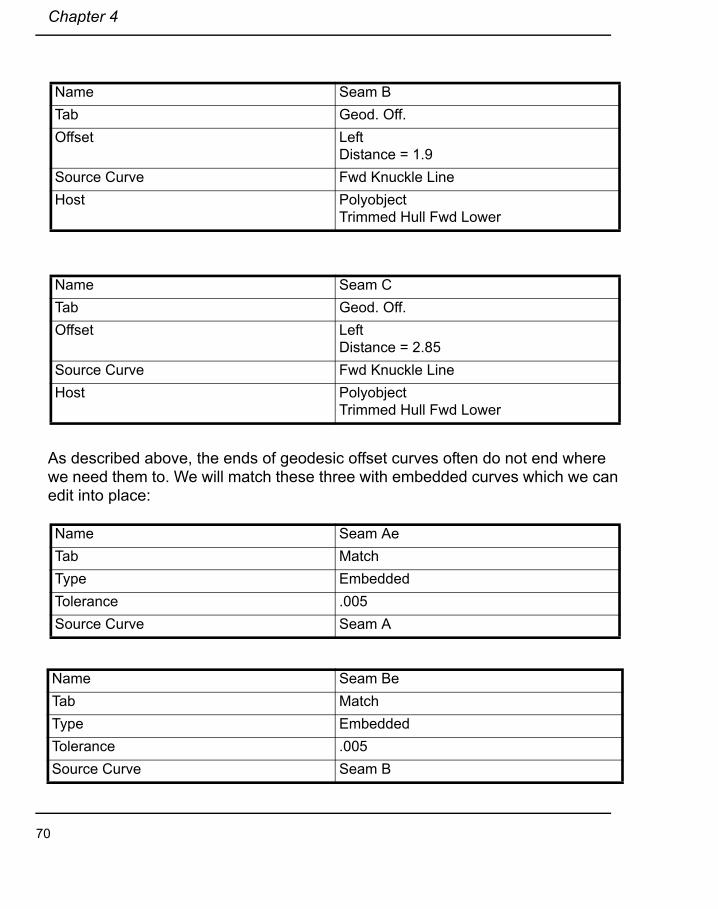
Chapter 4
As described above, the ends of geodesic offset curves often do not end where we need them to. We will match these three with embedded curves which we can edit into place:
Name Seam BTab Geod. Off.Offset Left
Distance = 1.9Source Curve Fwd Knuckle LineHost Polyobject
Trimmed Hull Fwd Lower
Name Seam CTab Geod. Off.Offset Left
Distance = 2.85Source Curve Fwd Knuckle LineHost Polyobject
Trimmed Hull Fwd Lower
Name Seam AeTab MatchType EmbeddedTolerance .005Source Curve Seam A
Name Seam BeTab MatchType EmbeddedTolerance .005Source Curve Seam B
70

Defining Plates on the Bow Flare
Then, make the source curves invisible (Attributes - click the "X" in the Vis col-umn). Finally, for each curve, select it, go to edit mode and pull the inboard control point across the centre line and let it snap back.
On this region of the hull, plate butts have no relationship to frames. In this example, we will stagger the butts. Since the stock length is 2m, the butts should be laid out at just less than 1m intervals. However, we will use this spacing only along the top edge of the lower hull surface and the butts will converge as they move down the flare. These butts are easily created as vertical projections of hor-izontal source curves. In the top view, create curves A1 Src, A2 Src and A3 Src, as shown below, and then project each curve onto polyobject Trimmed Hull Fwd Lower as Butt A1, Butt A2 and Butt A3. Note that you should be able to use Type 1 projected curves here.
Name Seam CeTab MatchType EmbeddedTolerance .005Source Curve Seam C
71

Chapter 4
With these curves in place, create 4 plates bounded by
1. Seam Ae and Butt A2 and the two edges of polyobject Trimmed Hull Fwd Lower;
2. Seam Ae, Seam Be and Butt A1 and one edge of polyobject Trimmed Hull Fwd Lower;
3. Seam Be, Seam Ce and Butt A2 and one edge of polyobject Trimmed Hull Fwd Lower;
4. Butt A1, Butt A3, Seam Ae, Seam Be.
In the New Plate dialogue for each plate, check Twin across centre plane and select the class Fwd Plating Group - Shop B - 8mm.
Select all of these plates and expand them as a group. Then view the strain maps for each. You will find that they consist of small irregular patches of expand and shrink of very small magnitude. This is just numerical noise and is an indication that the plates have almost no Gaussian curvature and need no forming other than bending to fit the conical shape of the hull at that point.
72

Defining a Panel and its Pin Jig
Defining a Panel and its Pin Jig
Autoplate has a facility for calculating pin jigs used for the assembly of several adjacent plates. Such an assembly is called a Panel. We will use the stern bulb plates as an example.
Select the Panel - New menu item. In the New Panel dialogue, highlight the names of the 6 plates on the Stern Bulb (Plates 3, 4, 5, 6, 7 and 8) and click the Add Selected button, then the OK button. Select Panel - Select, highlight Panel_1 and click OK. Select the Panel - PinJig menu item. The following dia-logue will appear:
Note that the selected plates are outlined in black and frames are shown in cyan. The view is along the average normal vector of the panel. That this is not parallel to the plane of the frames is revealed by the curvature of the frame lines.
Set the units to m and MinPinHgt to 0.5. Under spacing, click the On Seams radio button. Set Row Spacing and Pin Spacing to 1.0. The parallel red lines superim-posed on the drawing indicate pin layout rows. Because you selected On Seams,
73

Chapter 4
the program will place a pin everywhere a red line crosses a black plate outline. Further pins will be placed anywhere that the distance between two pins in a row exceeds the value Pin Spacing. Click the Grid radio button and you will see small cross bars on the red lines. These indicate pin locations at the interval Pin Spac-ing along each row.
Select Out in the Side frame; this means that the panel is to be assembled sitting on the pin jig with the inside facing up. Thus the jig placement marks in the DXF output will be drawn for placement on the outside of the plates.
Experiment with the Align controls to move the jig into the desired alignment with the plates of the panel. In the figure, no rotation was applied but the left shift but-ton was used to achieve the configuration shown.
74
DXF Output
DXF Output
Autoplate has facilities for producing several different DXF files. Under the Files - Export menu there is a sub-menu containing Plate DXF, Panel DXF and Shell Expansion entries. Now that we have created several plates and a panel we can exercise these export items.
Plate Drawings
Set the plating group to Aft Plating Group. From Plate - Select, select Plate_4 and Plate_5 from the bulb. Select Files - Export - Plate DXF.
In the Plate Output to DXF dialogue under 2D check the following boxes: Frames, Templates, Chord Lengths, Strain Contours and Data. Under 3D check Mesh and Frames. To the left of each check box is a small square. Click the one corre-sponding to Frames. A colour selection dialogue will appear. Click the red square. The small square in the original dialogue will change to that colour. Select the colours you want to use for each checked item.
Select m under units. Click OK. A dialogue in which you select the tutorial direc-tory will appear. The DXF files will be written to that directory. Click OK. You will find 4 files in that directory: 2dPlt_Plate_4.dxf, 2dPlt_Plate5.dxf, 3dPlt_Plate_4.dxf and 3dPlt_Plate_5.dxf
The first two contain 2D drawings and the last contain two 3D drawings. Start your CAD program and read in the first of these files. You will discover that
• there is a layer for each selected item and one for the plate outline.
• there is a layer for template layout and one for templates.
• layer colours are as chosen in the Plate Output to DXF dialogue.
• the chord length layer has straight lines joining various points on the plate. Each is labeled with the measurement between points taken through space on the hull.
• there is a layer containing a table of plate data in text form.
75

Chapter 4
Panel Drawings
The second DXF output is Panel. Choose the Panel - Select and select Panel_1. Then choose the Files - Export - Panel DXF menu item. In the dialogue, check all the boxes and set their colours. Click OK. Now you will find the file Panel_Panel_1.dxf in the chosen directory. Open this file in your CAD system. You will find a drawing of the panel with the markings you specified. The pin loca-tions are labeled with integer pairs (e.g. 4, 1). There is also a table in which pin information is presented, keyed to the pins by the same integer pairs.
Shell Expansion
Autoplate will also generate shell expansion drawings. Select Aft Plating Group and all the plates in it. Choose Files - Export - Shell Expansion. In the dialogue check all items and set their colours. Check Do Refinement and set the tolerance to .005 m. Click OK. The calculations take a little while, as marked by an hour-glass cursor. This time the created file is called Shell.dxf. In the drawing you will find that each chosen item has its own layer and the colour specified. Only selected plates appear.
Generating Reports
Choose Report - Create. In the Create Report dialogue, under Which Plates, select All and under Report Type, check both items. Click OK. After a period of calculation the Autoship Report Editor will appear. You will see that each plate in the project has an entry, and that at the end of the report there is a summary for all plates. The editor allows you to save the report to a file, to print it or to edit it.
76

Notes
77

Copyright 2004 Autoship Systems Corporation
Windows TM is a trademark of Microsoft CorporationAutoCAD® is a trademark of Autodesk, Inc