AUTO - INDEX SPIN / RELIEF REEL MOWER GRINDER€¦ · 6537951 (03-17) ACCU-Master 653 ACCU-Pro 633...
83
6537951 (03-17) ACCU-Master 653 ACCU-Pro 633 AUTO - INDEX SPIN / RELIEF REEL MOWER GRINDER with ACCU-Touch 3 Patent No. 6,010,394 6,290,581 & 6,685,544 SERVICE MANUAL You must thoroughly read and understand this manual before assembling or maintaining the equipment, paying parcular aenon to the Warning & Safety Instrucons. ORIGINAL INSTRUCTIONS
Transcript of AUTO - INDEX SPIN / RELIEF REEL MOWER GRINDER€¦ · 6537951 (03-17) ACCU-Master 653 ACCU-Pro 633...

6537951 (03-17)
ACCU-Master 653ACCU-Pro 633AUTO - INDEXSPIN / RELIEF
REEL MOWER GRINDERwith ACCU-Touch 3
Patent No. 6,010,3946,290,581 & 6,685,544
SERVICE MANUAL
You must thoroughly read and understand this manual before assembling or maintaining the equipment, paying particular attention to the Warning & Safety Instructions.
ORIGINAL INSTRUCTIONS

2
ORIGINAL INSTRUCTIONS
IMPORTANT SAFETY MESSAGE
As manufacturers of sharpening equipment, we want to confirm to you, our customers, our concern for safety. We also want to remind you about the simple, basic, and common sense rules of safety when using this equipment. Failure to follow these rules can result in severe injury or death to operators or bystanders.
It is essential that everyone involved in the assembly, operation, transport, maintenance, and storage of this equipment be aware, concerned, prudent, and properly trained in safety. Always use proper shielding and personal protective equipment as specified by the manufacturer.
Our current production machines include, as standard equipment, guards or shields for the grinding wheel, safety signs, and operators and service manuals. Never bypass or operate the machine with any of the guards or safety devices removed or without the proper personal safety equipment.
Read and fully understand all the safety practices discussed in this manual and the Operator's Manual . All safety rules must be understood and followed by anyone who works with reel grinders.
Before operating this grinder, an operator must read and understand all of the information in the operators manual and understand all of the safety signs attached to the product. A person who has not read or understood the Operator's Manual and safety signs is not qualified to operate the unit. Accidents occur often on machines that are used by someone who has not read the operators manual and is not familiar with the equipment. If you do not have an operators manual or current production safety signs, contact the manufacturer or your dealer immediately.
The equipment is designed for one-man operation. Never operate the equipment with anyone near, or in contact with, any part of the grinder. Be sure no one else, including bystanders, are near you when you operate this product.
Follow these simple, basic safety rules, as well as others, including:• Find and understand all safety signs in the operators manual and on the equipment. This will help
minimize the possibility of accidents and increase your productivity in using this product. • Be careful and make sure that everyone who operates the grinder knows and understands that it is a
very powerful piece of machinery, and if used improperly, serious injury or death may result. The final responsibility for safety rests with the operator of this machine.
This symbol is used throughout this manual to call attention to the safety procedures.
The word DANGER indicates an immediate hazardous situation, which if not avoided, will result in death or serious injury.
The word WARNING indicates a potential hazardous situation, which if not avoided, could result in death or serious injury.
The word CAUTION preceded with a safety alert symbol indicates a potential hazardous situation which, if not avoided, may result in minor or moderate injury.
Throughout this manual, the following safety symbols will be used to indicate the degree of certain hazards.
3
ORIGINAL INSTRUCTIONS
TABLE OF CONTENTSSafety Message ....................................................................................................................................... 2Safety Instructions .................................................................................................................................. 3 -6Service Data and Adjustments ............................................................................................................... 7 - 21Trouble-shooting .................................................................................................................................... 22 - 29Parts Diagrams........................................................................................................................................ 30 - 71Wiring Diagrams ..................................................................................................................................... 72 - 75Wiring Schematics .................................................................................................................................. 75 - 81PLC Input & Output Lights ...................................................................................................................... 82
This machine is designed for sharpening reel type mower ONLY. Any use other than this may cause personal injury and void the warranty.
To assure the quality and safety of your machine and to maintain the warranty, you MUST use original equipment manufacturer's replacement parts and have any repair work done by a qualified professional.
ALL operators of this equipment must be thoroughly trained BEFORE operating the equipment.
Do not use compressed air to clean grinding dust from the machine. This dust can cause personal injury as well as damage to the grinder.
Read the Operator's Manual before operating this equipment. Keep this manual handy for ready reference. Require all operators to read this manual carefully and become acquainted with all adjustments and operating procedures before attempting to operate the equipment. Replacement manuals can be obtained from your selling dealer or the manufacturer.
The equipment you have purchased has been carefully engineered and manufactured to provide dependable and satisfactory use. Like all mechanical products, it will require cleaning and upkeep. Lubricate and clean the unit as specified in the Operator's Manual. Please observe all safety information in this manual, the Operator's Manual and the safety decals on the equipment.
INSTALLATION, DAILY MAINTENANCE, AND BASIC UPKEEP IS DISCUSSED IN THE OPERATOR'S MANUAL. THIS MANUAL SHOULD BE USED IN CONJUNCTION WITH THE OPERATOR'S MANUAL FOR PERFORMING SERVICE ON THIS EQUIPMENT.

4
ORIGINAL INSTRUCTIONSSAFETY INSTRUCTIONS
13. MAINTAIN GRINDER WITH CARE. Follow instructions in Service Manual for lubrication and preventive maintenance.
14. DISCONNECT POWER BEFORE SERVICING, or when changing the grinding wheel.
15. REDUCE THE RISK OF UNINTENTIONAL STARTING. Make sure the switch is OFF before plugging in the Grinder.
16. USE RECOMMENDED ACCESSORIES. Consult the manual for recommended accessories. Using improper accessories may cause risk of personal injury.
17. CHECK DAMAGED PARTS. A guard or other part that is damaged or will not perform its intended function should be properly repaired or replaced.
18. NEVER LEAVE GRINDER RUNNING UNATTENDED. TURN POWER OFF. Do not leave grinder until it comes to a complete stop.
19. KNOW YOUR EQUIPMENT. Read this manualcarefully. Learn its application and limitations as well as specific potential hazards.
20. KEEP ALL SAFETY DECALS CLEAN AND LEGIBLE. If safety decals become damaged orillegible for any reason, replace immediately. Refer to replacement parts illustrations in Service Manual for the proper location and part numbers of safety decals.
21. DO NOT OPERATE GRINDER WHEN UNDER THE INFLUENCE OF DRUGS, ALCOHOL, OR MEDICATION.
1. KEEP GUARDS IN PLACE and in working order.
2. REMOVE WRENCHES AND OTHER TOOLS.
3. KEEP WORK AREA CLEAN.
4. DON'T USE IN DANGEROUS ENVIRONMENT. Don't use grinder in damp or wet locations. Machine is for indoor use only. Keep work area well lit.
5. KEEP ALL VISITORS AWAY. All visitors should be kept a safe distance from work area.
6. MAKE WORK AREA CHILD-PROOF withpadlocks or master switches.
7. DON'T FORCE THE GRINDER. It will do thejob better and safer if used as specified in thismanual.
8. USE THE RIGHT TOOL. Don't force the Grinder or an attachment to do a job for which it was not designed.
9. WEAR PROPER APPAREL. Wear no looseclothing, gloves, neckties, or jewelry which may get caught in moving parts. Nonslip footwear isrecommended. Wear protective hair covering to contain long hair. Wear respirator or filter mask where appropriate. Wear protective gloves.
10. ALWAYS USE SAFETY GLASSES.
11. SECURE YOUR WORK. Make certain that the cutting unit is securely fastened with the clampsprovided before operating.
12. DON'T OVERREACH. Keep proper footing and balance at all times.
TO AVOID INJURY, READ AND UNDERSTAND THE SAFETY ITEMS LISTED BELOW. IF YOU DO NOT UNDERSTAND ANY PART OF THIS MANUAL AND NEED ASSISTANCE, CONTACT YOUR LOCAL DEALER.

5
ORIGINAL INSTRUCTIONSSAFETY INSTRUCTIONSIMPROPER USE OF GRINDING WHEEL MAY CAUSE BREAKAGE AND SERIOUS INJURY.
DO1. DO always HANDLE AND STORE wheels in a CAREFUL manner.
2. DO VISUALLY INSPECT all wheels before mounting for possible damage.
3. DO CHECK MACHINE SPEED against the established maximum safe operating speed marked on wheel.
4. DO CHECK MOUNTING FLANGES for equal and correct diameter.
5. DO USE MOUNTING BLOTTERS when supplied with wheels.
6. DO be sure WORK REST is properly adjusted.
7. DO always USE A SAFETY GUARD COVERING at least one-half of the grinding wheel.
8. DO allow NEWLY MOUNTED WHEELS to run at operating speed, with guard in place, for at least one minute before grinding.
9. DO always WEAR SAFETY GLASSES or some type of eye protection when grinding.
DON'T1. DON'T use a cracked wheel or one that HAS BEEN DROPPED or has become damaged.
2. DON'T FORCE a wheel onto the machine OR ALTER the size of the mounting hole - if wheel won't fit the machine, get one that will.
3. DON'T ever EXCEED MAXIMUM OPERATING SPEED established for the wheel.
4. DON'T use mounting flanges on which the bearing surfaces ARE NOT CLEAN, FLAT AND FREE OF BURRS.
5. DON'T TIGHTEN the mounting nut excessively.
6. DON'T grind on the SIDE OF THE WHEEL (see Safety Code B7.2 for exception).
7. DON'T start the machine until the WHEEL GUARD IS IN PLACE.
8. DON'T JAM work into the wheel.
9. DON'T STAND DIRECTLY IN FRONT of a grinding wheel whenever a grinder is started.
10. DON'T FORCE GRINDING so that motor slows noticeably or work gets hot.
AVOID INHALATION OF DUST generated by grinding and cutting operations. Exposure to dust may cause respiratory ailments. Use approved NIOSH or MSHA respirators, safety glasses or face shields, and protective clothing. Provide adequate ventilation to eliminate dust, or to maintain dust level below the Threshold Limit Value for nuisance dust as classified by local codes.
GRINDING IS A SAFE OPERATION IF THE FEW BASIC RULES LISTED BELOW ARE FOLLOWED. THESE RULES ARE BASED ON MATERIAL CONTAINED IN THE ANSI B7.1 SAFETY CODE FOR "USE, CARE AND PROTECTION OF ABRASIVE WHEELS". FOR YOUR SAFETY, WE SUGGEST YOU BENEFIT FROM THE EXPERIENCE OF OTHERS AND CAREFULLY FOLLOW THESE RULES.

6
ORIGINAL INSTRUCTIONSSERVICE DATA
IMPORTANT GROUNDING INSTRUCTIONS
If electrical testing is required, always verify the machine has a proper ground before performing any tests.
In case of a malfunction or breakdown, grounding reduces the risk of electrical shock by providing a path of least resistance for electrical current.
This Grinder has an electrical cord with an equipment grounding conductor and a grounding plug. The plug must be plugged into a matching outlet that is properly installed and grounded according to all local or other appropriate electrical codes and ordinances.
Before plugging in the Grinder, make sure it will be connected to a supply circuit protected by a properly sized circuit breaker or fuse. SEE SERIAL NUMBER PLATE FOR FULL LOAD AMP RATING OF YOUR MACHINE.
Never modify the plug provided with the machine--if it won't fit the outlet, have a proper outlet and cir-cuit installed by a qualified electrician.
ALWAYS PROVIDE A PROPER ELECTRICAL GROUND FOR YOUR MACHINE. AN IMPROPER CONNECTION CAN CAUSE A DANGEROUS ELECTRICAL SHOCK. IF YOU ARE UNSURE OF THE PROPER ELECTRICAL GROUNDING PROCEDURE, CONTACT A QUALIFIED ELECTRICIAN.
UNPLUG THE EQUIPMENT PRIOR TO DOING ANY SERVICE ON THIS EQUIPMENT. FAILURE TO REMOVE POWER TO THIS EQUIPMENT BEFORE SERVICING MAY RESULT IN INJURY OR DEATH.
IF POWER IS REQUIRED FOR TESTING OR TROUBLESHOOTING, THIS SHOULD BE PERFORMED BY A TRAINED PROFESSIONAL OR LICENSED ELECTRICIAN.
REVIEW THE SYMBOLS AND DESCRIPTIONS ON PAGES 10 AND 11 OF THE OPERATOR'S MANUAL. UNDERSTAND ALL SYMBOLS BEFORE OPERATING OR SERVICING THIS EQUIPMENT.
This is the electrical hazard symbol. It indicates that there are DANGEROUS HIGH VOLTAGES PRESENT inside the enclosure of this product. TO REDUCE THE RISK OF FIRE OR ELECTRIC SHOCK, do not attempt to open the enclosure or gain access to areas where you are not instructed to do so. REFER SERVICING TO QUALIFIED SERVICE PERSONNEL ONLY.

7
ORIGINAL INSTRUCTIONS
GRADE 2 GRADE 5 GRADE 8
SMOOTH 3 MARKS 6 MARKS HEAD on HEAD on HEAD
1/4 In. 6 ft-lbs 9 ft-lbs 13 ft-lbs thread (0.8 kg-m) (1.25 kg-m) (1.8 kg-m)
5/16 In. 11 ft-lbs 18 ft-lbs 28 ft-lbs thread (1.5 kg-m) (2.5 kg-m) (3.9 kg-m)
3/8 In. 19 ft-lbs 31 ft-lbs 46 ft-lbs thread (2.6 kg-m) (4.3 kg-m) (6.4 kg-m)
7/16 In. 30 ft-lbs 50 ft-lbs 75 ft-lbs thread (4.1 kg-m) (6.9 kg-m) (10.4 kg-m)
1/2 In. 45 ft-lbs 75 ft-lbs 115 ft-lbs thread (6.2 kg-m) (10.4 kg-m) (15.9 kg-m)
SERVICE DATASKILL AND TRAINING REQUIRED FOR SERVICING
This Service Manual is designed for technicians who have the necessary mechanical and electricalknowledge and skills to reliably test and repair the this Spin/Relief Grinder. For those without the background, service can be arranged through your local distributor.
This section presumes that you are already familiar with the normal operation of the grinder. If not, you should read the operators manual, or do the servicing in conjunction with someone who is familiar with its operation.
Persons without the necessary knowledge and skills should not remove any panels or shields, or attempt any internal troubleshooting, adjustments, or parts replacement.
If you have questions not answered in this manual, please contact your distributor.
Throughout this manual we refer to torque requirements as "firmly tighten" or the like. For more specific torque values, refer to the information below.
Bolts Going Into a Nut, or Into a Thread Hole in Steel.Refer to the Table at the right.
Bolts Going Into a Thread Hole In AluminumUse the Grade 2 Values in the Table at the right.
Socket-Head Screws Going Into a Nut or Steel Use the Grade 8 Values in the Table at the right.
Machine ScrewsNo. 6 screws: 11 in.- lbs (0.125kg - m)No. 8 screws: 20 in. - lbs (0.23 kg - m)No. 10 screws: 32 in. - lbs (0.37 kg - m)
TORQUE REQUIREMENTS

8
ORIGINAL INSTRUCTIONS
RELIEF ADJUSTING LEAD SCREW
PERIODIC MAINTENANCE
FIG. 2
LEAD SCREW (2X)
ALIGNMENT SHAFT (2X)
FIG. 1
DAILY MAINTENANCE IS SPECIFIED ON PAGE 5 OF THE OPERATOR'S MANUAL, AND IS TO BE PERFORMED BY THE OPERATOR.
LISTED BELOW ARE PERIODIC MAINTENANCE ITEMS TO BE PERFORMED BY YOUR COMPANY'S MAINTENANCE DEPARTMENT:
1. Clean the tank and filter of the vacuum system weekly or more often depending on the number of reels ground. (Vacuum system is optional equipment on the 633.)
2. Inspect the grinding wheel poly-V belt for cracking and adjust the belt tension per procedure called out in the adjustment section every six months.
3. Wipe and re-lube the vertical and horizontal alignment shafts and lead screws with Never-Seez™ every six months. See FIG. 1.
4. Lift the bellows and wipe off the bearing rails monthly. To lubricate linear bearing, follow the lubrication procedure on the following pages. Generally, this will be every six months to a year.
5. Wipe and re-oil the index finger adjustment screw with spray lubricant every 3 months. Wipe off excess lubricant.
6. Check the traverse belt for cracking, uneven wear or other defects every 6 months to a year.
7. Clean the indicator rod on the Accu-Positioning Gauge. Wipe with a clean rag until the unit moves smoothly. Generally, this will be every six months to a year.

9
ORIGINAL INSTRUCTIONSPERIODIC MAINTENANCESTORAGE PROCEDURE
It is important to follow the procedures below when placing your grinder in storage for an extended period of time. Proper care will help maintain the working functions of the grinder and decrease maintenance and problems that occur when storing the grinder.
BEFORE STORING THE GRINDER:
-Clean the machine thoroughly. DO NOT USE COMPRESSED AIR OR A POWER WASHER TO CLEAN THIS MACHINE!
-Lubricate the following parts by flooding the area with a spray lubricant and leaving it in place: DO NOT USE A TEFLON BASED LUBRICANT!
1. Traverse Shafts & Linear bearings (see Lubrication Section of manual).2. Remove grinding wheel and spray the movable parts of the finger system.3. Cross slide shafts and adjustment screws (Right side of Traverse Base).4. Scratches in the paint or any other bare metal surfaces.
-Work the lubricant in by moving parts through their full range of motion.
-Make sure all controls are in the OFF position and unplug the unit from the wall. -Cover the unit if possible with a sheet or tarp.
BRINGING THE UNIT BACK INTO SERVICE:
-Remove the cover and reapply lubricant to the items stated above. Wipe off all excess lubricant. (See Lubrication section for more details.)
-Plug the unit into the wall and test all electrical functions.
-Check the belts for cracking and adjust the tension if necessary.
-Check for damaged or missing parts.
10
ORIGINAL INSTRUCTIONSLUBRICATION
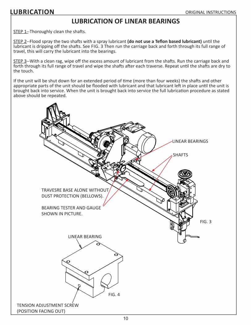
STEP 1--Thoroughly clean the shafts.
STEP 2--Flood spray the two shafts with a spray lubricant (do not use a Teflon based lubricant) until the lubricant is dripping off the shafts. See FIG. 3 Then run the carriage back and forth through its full range of travel, this will carry the lubricant into the bearings.
STEP 3--With a clean rag, wipe off the excess amount of lubricant from the shafts. Run the carriage back and forth through its full range of travel and wipe the shafts after each traverse. Repeat until the shafts are dry to the touch.
If the unit will be shut down for an extended period of time (more than four weeks) the shafts and other appropriate parts of the unit should be flooded with lubricant and that lubricant left in place until the unit is brought back into service. When the unit is brought back into service the full lubrication procedure as stated above should be repeated.
LUBRICATION OF LINEAR BEARINGS
LINEAR BEARING
TENSION ADJUSTMENT SCREW (POSITION FACING OUT)
FIG. 3
FIG. 4
TRAVESRE BASE ALONE WITHOUT DUST PROTECTION (BELLOWS).
BEARING TESTER AND GAUGE SHOWN IN PICTURE.
SHAFTS
LINEAR BEARINGS
11
ORIGINAL INSTRUCTIONSADJUSTMENTS
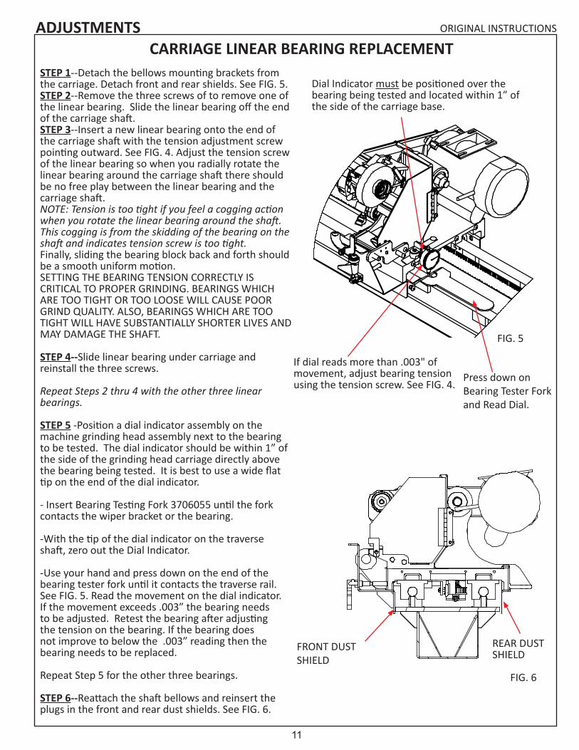
STEP 1--Detach the bellows mounting brackets from the carriage. Detach front and rear shields. See FIG. 5.STEP 2--Remove the three screws of to remove one of the linear bearing. Slide the linear bearing off the end of the carriage shaft.STEP 3--Insert a new linear bearing onto the end of the carriage shaft with the tension adjustment screw pointing outward. See FIG. 4. Adjust the tension screw of the linear bearing so when you radially rotate the linear bearing around the carriage shaft there should be no free play between the linear bearing and the carriage shaft.NOTE: Tension is too tight if you feel a cogging action when you rotate the linear bearing around the shaft. This cogging is from the skidding of the bearing on the shaft and indicates tension screw is too tight.Finally, sliding the bearing block back and forth should be a smooth uniform motion.SETTING THE BEARING TENSION CORRECTLY IS CRITICAL TO PROPER GRINDING. BEARINGS WHICH ARE TOO TIGHT OR TOO LOOSE WILL CAUSE POOR GRIND QUALITY. ALSO, BEARINGS WHICH ARE TOO TIGHT WILL HAVE SUBSTANTIALLY SHORTER LIVES AND MAY DAMAGE THE SHAFT.
STEP 4--Slide linear bearing under carriage and reinstall the three screws.
Repeat Steps 2 thru 4 with the other three linear bearings.
STEP 5 -Position a dial indicator assembly on the machine grinding head assembly next to the bearing to be tested. The dial indicator should be within 1” of the side of the grinding head carriage directly above the bearing being tested. It is best to use a wide flat tip on the end of the dial indicator.
- Insert Bearing Testing Fork 3706055 until the fork contacts the wiper bracket or the bearing.
-With the tip of the dial indicator on the traverse shaft, zero out the Dial Indicator.
-Use your hand and press down on the end of the bearing tester fork until it contacts the traverse rail. See FIG. 5. Read the movement on the dial indicator. If the movement exceeds .003” the bearing needs to be adjusted. Retest the bearing after adjusting the tension on the bearing. If the bearing does not improve to below the .003” reading then the bearing needs to be replaced.
Repeat Step 5 for the other three bearings.
STEP 6--Reattach the shaft bellows and reinsert the plugs in the front and rear dust shields. See FIG. 6.
CARRIAGE LINEAR BEARING REPLACEMENT
REAR DUST SHIELD
FRONT DUST SHIELD
If dial reads more than .003" of movement, adjust bearing tension using the tension screw. See FIG. 4.
FIG. 6
FIG. 5
Dial Indicator must be positioned over the bearing being tested and located within 1” of the side of the carriage base.
Press down on Bearing Tester Fork and Read Dial.

12
ORIGINAL INSTRUCTIONSADJUSTMENTSRELIEF ASSEMBLY INDEX FINGER ADJUSTING KNOB AND FREE-PLAY SETSCREWS.
If the index finger stop position is moving during grinding, adjust the tightness of the nylon plug to the knob assembly threads. The tightness has to be sufficient so the knob assembly does not rotate during grinding cycle. See FIG 7.
If the finger assembly does not move freely or has to much free-play when loosened, Adjust the 2 nylon tip set screws on the side of the assembly. FIG. 8
NOTE: To adjust the nylon plug you must allow the index finger to travel to its furthest UP position.
GRINDING HEAD BELT TENSION ADJUSTMENT
The left side grip grinding wheel knob must be removed for belt tensioning adjustment. Remove the screws holding the vacuum hose bracket, the two double tube clamps and the belt cover. For grinding motor belt adjustment, loosen the four socket head cap screws that attach the motor mounting plate. Adjust the grinding motor for proper belt tension and tighten the four socket head cap screws. Proper belt tension is achieved when 5 lbs of force applied to the belt halfway between the two pulleys results in .12" (3 mm) of deflection. See FIG 9.
To verify belt tension mount the belt guard with two screws. Turn the motor on. If the belt is tensioned correctly, start-up torque of the motor through the pulley to the belt should have zero slippage. If there is belt slippage there will be a slight squeal before the belt comes up to speed. When you achieve correct tension, reassemble all of the remaining parts that have been removed.
FIG. 7
FIG. 8NYLON TIP SET SCREWS
NYLON PLUG
.12" [3 mm]
RELIEF ADJUSTING LEAD SCREW
FIG. 9

13
ORIGINAL INSTRUCTIONS
FIG. 10
SENSOR LIGHTINDEX FINGER SENSOR
SENSING PIN
ADJUSTMENTS
1/16" [1.5mm]INDEX FINGER SENSOR SETTING
Press the machine system start switch, so the grinder is operational.
Push down on the index finger until the stop pin is within .06 inches (1.5 mm) of bottoming out. (You can use a 1/16" gauge pin or rod stock between the stop pin and index finger). Set the proximity switch to activate the light at this setting. This assures the index finger to be close to its final stop position so the reel is completely indexed before the carriage starts to traverse. See FIG. 10.
The spring load force pushing up on the index finger brings it away from the proximity when released.
STEPPPER INFEED TRAVEL LIMITS
The infeed stepper maximum extension is 6.0" (152 mm) and minimum compression is 3.5" (89 mm). If you experience a situation where the grind does not properly finish, check that you have not exceeded stepper travel by checking the values per FIG. 11.
FIG. 11

14
ORIGINAL INSTRUCTIONS
TRAVEL LIMITSFor the TRAVEL LIMITS to perform properly and reverse the direction of the carriage at each end of the rails, a distance of 3/16”[4 mm] to ¼” [6 mm] needs to be maintained between the limit sensor bracket and the TRAVEL LIMIT. See FIG. 12.
NOTE: the light on the TRAVEL LIMIT switch activates when metal crosses in front of the switch.
ADJUSTMENTS
ADJUSTABLE RELIEF TENSIONIf the relief angle appears to vary during relief grinding adjust the tension on the nylon plug and set screw. See FIG. 13.
FIG. 123/16" [4 mm] to 1/4" [6mm]
FIG. 13
SET SCREW WITH NYLON PLUG
SAFETY SWITCH ALIGNMENT
For the safety switches to work properly they must be adjusted so the sender and receiver are parallel to each other with a maximum gap of .19 inches (5 mm). A special wrench is needed to adjust the safety screws used to hold the switch in place.
.19" (5mm)
FIG. 14

15
ORIGINAL INSTRUCTIONS
SPIN MOTOR ADJUSTMENT
If the spin drive motor is moving during operation, or does not move freely into position, adjust the tension of the 2 T-Handles. See FIG. 15.
ADJUSTMENTS
FIG. 15
T-HANDLES
TRAVERSE BELT TENSION
To adjust the tension on the traverse belt, tighten the screws and nuts located at the left side of the traverse belt. Tighten the nuts until the compression springs measure 3/4" [19mm]. See FIG. 16. If the springs are not tensioned equally, uneven loading on the traverse system may cause parts to fail.
DO NOT OVERTIGHTEN. OVERTIGHTENING COULD DAMAGE THE BELT OR TRAVERSE DRIVE SYSTEM.
TRAVERSE CLAMP FORCE
If the traverse clamp is slipping during regular operation it may be necessary to tighten the clamp. To tighten, loosen the jam nut on the clamp tip. Screw the tip out so there is .10" gap between the tip and the Clamp Support Block. See FIG 17. Lock in place by tightening the jam nut against the clamp being careful not to move the tip. Verify the distance between the clamp tip and block is still .10". The .10" setting allows slippage in a jam situation and damage can occur if this adjustment is set to narrow.
CAUTION SHOULD BE USED AS ADJUSTING THE TIP WILL AFFECT THE SLIP LOAD AND COULD DAMAGE THE CLAMP TIP, BELT OR TRAVERSE DRIVE SYSTEM.
FIG. 16
FIG. 17

16
ORIGINAL INSTRUCTIONS
ADJUSTING CROSS SLIDE ASSEMBLY
If the cross slide becomes very difficult to turn it may become necessary to adjust the assembly. To relieve the tension on the assembly follow the procedure listed below:
STEP 1—Turn the vertical handwheel on the cross-slide counter-clockwise to raise the carriage base up until you are able to slide a piece of wood or metal (such as two 2 x 4s) under the carriage base. Be sure to insert this on the seam of the floor pan under where the right side leg is welded. Release the pressure on the cross slide by lowering the base until the base is supported by the wood/metal piece and the pressure on the cross slide is removed. STEP 2—Knock out the pins on either side of the mounting frame adjuster and loosen the 4 bolts (B504801) that connect the carriage mounting bracket to the frame of the grinder.STEP 3—Turn the Vertical handwheel clockwise to raise the cross slide assembly, this will put a preload on the cross slide assembly to the up position. STEP 4—Tighten the 4 bolts on the Carriage Mounting Frame to 75 ft-lbs.STEP 5-- Turn the vertical handwheel counter-clockwise to raise the carriage base and remove the wood/metal support (example: the two 2 x 4s). Test the vertical and horizontal handwheels for ease of movement through their full range of motion.STEP 6—If the cross slides tend to bind, repeat above steps 3-5 above until the handwheels move freely through there full range of travel. STEP 7—when the cross slides move freely drill new holes and repin the assembly.
ADJUSTMENTS
BOLTS
PIN
PIN
BOLTS
CROSS SLIDE ASSEMBLY
CARRIAGE MOUNTING BRACKET
PART OF FRAME
FIG. 18

17
ORIGINAL INSTRUCTIONSADJUSTMENTSCROSS SLIDE SHAFT REPLACEMENT
If the cross slide shafts become scarred or gnarled, replace them by the following procedure:
STEP 1--Turn the vertical handwheel on the cross-slide counter-clockwise to raise the carriage base up until you are able to slide a piece of wood or metal (such as two 2 x 4s) under the carriage base. Be sure to insert this on the seam of the floor pan under where the right side leg is welded. Release the pressure on the cross slide by lowering the base until the base is supported by the wood/metal piece and the pressure on the cross slide is removed. STEP 2--Loosen the two nuts on the support casting that hold the locking stud and tap the ends of the studs with plastic or rubber hammer to loosen.STEP 3--Loosen the lock handles and tap the center of the handle with a plastic hammer to loosen.STEP 4--Loosen locknut and setscrew on the handwheels and remove.STEP 5--Remove the Slide Shafts.STEP 6--Remove all burrs and resurface the shaft to a clean, smooth, polished surface. (OR REPLACE WITH A NEW SHAFT.)STEP 7--Coat the shaft with Never-Seez™ and re-install the shaft through the Support, Cross Slide Block and the three locking studs. The shaft must move freely inside the Cross Slide Block before reassembling. STEP 8--Retightening the nuts at the end of the locking studs to lock shaft in place.STEP 9--Reinstall the Handwheel by snugging the setscrew to the flat located on the screw shaft, now tighten the nut until tight then back the nut off by 1/2 turn. Tighten the setscrew to 70 in-lbs.STEP 10--Test the Cross Slide, the handwheel should turn freely.STEP 11-- Turn the Vertical Handwheel to raise the Carriage Base and remove the wood/metal supports (two 2 x 4s). Test the vertical and horizontal handwheels for ease of movement through their full range of motion. If binding occurs, follow the procedure under Cross Slide Assembly located on the previous page.
NOTE: it is also possible to remove the complete Cross Slide Assembly and do the repairs on a bench then reinstall.
LOCKNUT
CROSS SLIDE
LOCK HANDLES
SLIDE SHAFTSLOCKING STUDS (DUTCHMAN)
NUT
LOCKNUT
HANDWHEELSETSCREW
FIG. 20
FIG. 19

18
ORIGINAL INSTRUCTIONS
REPLACEMENT OF GRINDING HEAD SHAFT & BEARINGS
Remove grinding wheel and grinding wheel knob. The Grinding Head Spindle Assembly consists of the grinding head spindle and a ball bearing press fit together. The left side ball bearing is slip fit on the opposite end. To replace the spindle assembly remove the left side grinding wheel grip knob, square key and belt cover. See FIG. 21. Loosen the 4 socket head cap screws on the motor plate to remove the poly-V belt. Loosen the 2 set screws on the spindle pulley and remove the pulley, square key and pulley spacer. Push on the right hand side of the spindle assembly to compress conical washers so there is no pressure on the shaft retaining ring. Using a retaining ring pliers remove the small external retaining ring from the spindle assembly. You can now remove the spindle assembly out the right side by lightly tapping on the left end with a rubber mallet. The second ball bearing can be removed from the belt side of the Grinding Head Housing.
To reassemble place the 4 conical washers (2 Pair nested and then place the 2 pairs back to back) against the ball bearing on the new spindle assembly. See FIG. 22. Thoroughly clean the housing bore and the outside diameter of both bearings. APPLY BLUE LOCTITE #243 TO THE OUTSIDE DIAMETER OF THE TWO BEARINGS. Slide the spindle assembly into the right side of the Grinding Head Housing. Install the bearing sleeve against the bearing on the spindle assembly. Slip fit the new left side ball bearing onto the spindle assembly and into grinding head housing. APPLY BLUE LOCTITE #243 TO THE INSIDE THREAD OF THE 9/16-18 NUT and install onto the spindle shaft with the grooved side toward the bearing onto the spindle shaft and using a spanner wrench on the right side of the spindle and a 7/8 deep-well socket on the left side, torque the locknut to 15 Ft/Lbs.
APPLY BLUE LOCTITE #243 TO THE BORE OF THE PULLEY BEFORE INSTALLATION. Replace the square key and install the new pulley pushing the counter-bore side of the pulley against the spindle nut with no end play. NEXT INSTALL BLUE LOCTITE #243 ON THE PULLEY SETSCREWS AND TIGHTEN THE TWO PULLEY SET SCREWS. Then install the new external retaining ring on the spindle shaft. Mount the new poly-V belt. (See Grinding Head Belt Tension and Alignment Adjustments in the adjusting section of the manual). Install the new belt cover gasket on the belt cover and install the belt cover and square key. Mount the left side grinding wheel grip knob with a slight gap to the cover and tighten the two set screws.
MACHINE SERVICE
FIG. 21 FIG. 22

19
ORIGINAL INSTRUCTIONSMACHINE SERVICE
FIG. 23
TRAVERSE DRIVE CONTROL BOARD (TDC)The Traverse Drive Control Board has nine potentiometers and four switches as shown on drawing 6524511 which is included. These potentiometers and switches have been set at the factory to the positions shown on the drawing.Also see FIG. 23 and FIG. 24.
Fwd Accel & Rev Accel---FWD ACC & REV ACCThe potentiometer is factory preset to the minimum full counterclockwise 8:30 position. This position turns the Acceleration/Deceleration off for this application.
Maximum Speed---MAX SPDThe maximum speed potentiometer is preset to position for 90 Volts DC output to the traverse motor at terminals A1 and A2.
IR Compensation---IR COMPThe IR Comp control is preset to 3:00 position. Never adjust past the 4:30 position.
Regulation of the traverse motor may be improved by slight adjustment of the IR COMP trim pot clockwise from its factory set position. Overcompensation causes the motor to oscillate or to increase speed when fully loaded. If you reach such a point, turn the IR COMP trim pot counterclockwise until the symptoms just disappear.
Rev Torque---REV TQThe Reverse Torque setting determines the maximum current limit for driving the motor in the reverse direction. The potentiometer is preset to the 10:30 position. It should not require adjustment.
Fwd Torque---FWD TQThe Forward Torque setting determines the maximum current limit for driving the motor in the forward direction. The potentiometer is preset to the 10:30 position. It should not require adjustment.
Deadband---DBThis motor control board has a potentiometer which must be set for 50 HZ or 60 HZ operation. For 60 HZ set to 3:00 position. For 50 HZ set to 9:00 position. Minimum Speed---MIN SPDThe potentiometer is factory preset to the minimum full counterclockwise 8:30 position.
Tach---TACHThe tach potentiometer is not used in this application. It should be a the factory setting of 8:30.
Armature Switch---ARMATURE 90-180This switch is factory preset to the 90 position for a 90 VDC motor..
Feedback Switch--- FEEDBACK ARM-TACHThis switch is factory preset to the ARM position.
The lower control board has two switches. Both switches are factory preset to 115 for 115 VAC operation.
Potentiometer Clock Orientation
Terminal ends (Feet) are always at the 6:00 position,no matter how the potentiometer is orientated on the board.
FIG. 24

20
ORIGINAL INSTRUCTIONS
The Spin Drive Control Board has four potentiometers, two switches and one dial as shown on FIG. 24. These potentiometers,switches and dial have been set at the factory to the positions shown on FIG. 24.
Relief Grinding ModeThe Torque Shut Off mode selector allows you to turn on or off the Torque Shut Off feature. When switch 1 is set to ON, the board will decrease the spin motor torque once the shut time is achieved after leaving the right proximity sensor. The amount of time it takes before the torque is decreased is set with the Torque Shut Off Delay dial. The spin motor torque will be increased to the higher value once the right proximity switch is activated again. If the Torque Shut Off selector is in the OFF position the torque will remain constant during relief grinding.
Torque Shut Off Delay dial is used to set the duration of time before the torque is decreased after leaving the right proximity sensor during relief grinding. If the dial is turned clockwise (higher number) the higher torque value will stay on for a longer period of time.
The Relief Speed (RSP) and the Relief Torque Pot (RTP) interact with each other. The (RSP) is located on the spin board as a remote speed preset at 12:00 (20 Volts DC). See FIG. 24. The (RTP) is located on the control panel and is for relief torque adjustment.
Relief Speed Pot (RSP) when rotated clockwise will increase spin drive speed (the speed at which the reel indexes to the next blade). This speed should never be above the 3:00 setting.
Relief Torque Pot (RTP) is used to vary the reel to finger holding torque for relief grinding. The recommended starting point is 30 in/lbs of torque setting. Never adjust the (RTP) potentiometer dial past the red line marking. Setting the reel to finger torque to high could cause the spin motor system to not operate smoothly.
Relief Idle Torque Pot (ITP) is used to vary the reel to finger holding torque once the shut time is achieved after leaving the right proximity sensor if the Torque Shut Off Selector is set to ON.
Spin Grinding Mode The Spin Torque Potentiometer (STP) and the Spin Speed Pot (SSP) interact with each other. The (STP) is located on the spin board as remote torque preset at 2:00 for torque setting. See FIG. 25. The (SSP) is located on the control panel and is for spin speed adjustment.
Spin Torque Pot (STP) controls maximum torque allowable in the spin grinding cycle only. This should never be adjusted past the 3:00 position. If the reel does not turn check that the reel is free turning by hand spinning with the power off and the spin drive disconnected.
The Spin speed Pot (SSP) controls reel spin speed, adjust as required. This controls the spin drive speed for spinning the reel.
IR COMP PotThe IR Compensation is factory set at 9:00.
Regulation of the spin or relief grind spin motor may be improved by a slight adjustment of the IR COMP pot clockwise from its factory-set position. Overcompensation causes the motor to oscillate or to increase speed when fully loaded. If you reach such a point, turn the IR COMP pot counterclockwise until symptoms disappear.
MACHINE SERVICESPIN DRIVE CONTROL BOARD (SDC)

21
ORIGINAL INSTRUCTIONS
3:009:00
6:00
12:00
Potentiometer Clock Orientation
FIG. 25
SPIN TORQUE POT (STP) 2:00
IR COMP POT 9:00IDLE TORQUE POT (ITP) 10:00
RELIEF SPEEDPOT (RSP) 12:00
SWITCH 1 SET TO OFF
DELAY SET TO 1
MACHINE SERVICE
STEPPER INFEED CONTROLLER (SIC)The Stepper Infeed Controller has a set of 4 dip switches on the side SWB1-4 and 8 dip switches on the top SWA1-8 . See FIG. 26.
DIP SWITCH SETTINGS:
Switches SWB1-3 are on the side of the control and are used to select the motor type used.SWB1= ONSWB2=ONSWB3= OFF
Switch SWB4 located on the side and controls the LOAD INERTIA.SWB4= ON
Switches SWA1- SWA8 are located on top:
Switch SWA1 can be used to preform a self testSWA1 - OFF Switch SWA2 selects the noise filter setting SWA2 - ONSwitch SWA3 selects the IDLE CURRENT (on=50%, 0ff=90%)SWA3 - ON Switches SWA4-5 select the % Max CurrentSWA4 - OFFSWA5 - OFFSwitches SWA6-8 select the Steps/revolution. SWA6 - ONSWA7 - OFFSWA8 - ON
SWA8 - ONSWA7 - OFFSWA6 - ONSWA5 - OFFSWA4 - OFFSWA3 - ONSWA2 - ONSWA1-OFF
SWITCHES ON SIDEB-1,2,4 = ON3 = OFF
FIG. 26

22
ORIGINAL INSTRUCTIONS
ACCU-TOUCH CONTROL PANEL
3.
4.
5.
6.
1.ELECTRICAL TROUBLESHOOTING
2.
8.
9.
7.
10.
11.
12.
13.
14.
15.
16.
17.
18.
19.
20.
FIG. 27

23
ORIGINAL INSTRUCTIONS
ACCU-TOUCH CONTROL PANEL1. Stepper Infeed Controller (SIC)
2. Output Control Relays (RYX)
3. Door Safety Switch Monitor (SSM)
4. Tiered Terminal Block (TT0- TT6)
5. Programmable Logic Controller (PLC)
6. Low Voltage Relay (LVR)
7. Main Circuit Breaker (MCB)
8. Magnetic Contactor (MAG)
9. Power Filter (FTR)
10. Terminal Blocks-(TBG) - GRIND MOTOR -(TBS) - SPIN MOTOR-(TBT) - TRAVERSE MOTOR-(TBF) - FLASHER-(TBW) - WINCH-(TBV) - VACUUM-(TBL) - LIGHT
11. Start Relay (SRL)
12. Grinding Motor Overload Relay
13. Grinding Motor Relay (REL)
14. Grey Terminal Blocks (GTX) Blue Terminal Blocks (BTX)
15. Grind Motor Circuit Breaker (GCB)
16. Vacuum/Winch Circuit Breaker (VCB)
17. Traverse Drive Control Board (TDC)
18. Spin Drive Control Board (SDC)
19. Gauge/Spin Interface Board (GSI)
20. 24 VDC Power Supply (PWR)
ELECTRICAL TROUBLESHOOTING

24
ORIGINAL INSTRUCTIONS
SKILL AND TRAINING REQUIRED FOR ELECTRICAL SERVICING
This Electrical Troubleshooting section is designed for technicians who have the necessary electrical knowledge and skills to reliably test and repair the ACCU-Touch electrical system. For those without that background, service can be arranged through your local distributor.
This manual presumes that you are already familiar with the normal operation of the grinder. If not, you should read the Operator's Manual, or do the servicing in conjunction with someone who is familiar with its operation.
Persons without the necessary knowledge and skills should not remove the control box cover or attempt any internal troubleshooting, adjustments, or parts replacement.
If you have any question not answered in this manual, please call your distributor. They will contact the manufacturer if necessary.
WIRE LABELS
All wires on the ACCU-Master have a wire label at each end for assembly and troubleshooting. The wire label has a code which tells you wiring information. The first set of two or three numbers are the Foley wire number. The next group of letters or numbers are the code for the component to which the wire attaches. Example: RT1 for Relay Terminal 1. The last set of numbers or letters is the name of the terminal on the component to which the wire attaches.
TERMINAL BLOCKS:
To insert or remove a wire from the terminal block, insert a small screw driver into the square hole. Then insert or remove wire from the round hole. Remove screwdriver to lock the wire in place.
Note the square hole can also be used when checking for voltages. The probe tip of the multimeter can be inserted into the square hole to take readings.
ELECTRICAL TROUBLESHOOTING
FIG. 28

25
ORIGINAL INSTRUCTIONS
PROBLEM--Machine will not power up or is stuck in E-stop. In your Product Packet Assembly, there are a series of prints. Find the print titled ACCU-Touch Wiring Diagram, before starting the troubleshooting below. Verify all wires shown on that drawing are correct and pull on wire terminals with approximately 3 lbs force to verify there are no loose terminal connections and/or no loose crimps between wire and terminal. If loose terminals are found, retighten and retest system. If problem persists, test as listed below.Possible Cause Checkout ProcedureYou must turn ON the Switch on the Side of the machine
A. Turn switch to the on Posi-tion. Look for screen to come on.
Machine works: Yes--End Trouble ShootingNo-- Go go Step B. next
Main Power Cord is not plugged in
B. Plug in the main power cord Machine works: Yes--End Trouble ShootingNo-- Go go Step B. next
Building Circuit breaker has tripped
C. Check circuit breaker in building electrical panel. Reset if needed. (Check wall outlet to make sure it works.)
Machine works: Yes--End Trouble ShootingNo--but a light works in the outlet. Go to step D. nextNo- Light does not work in outlet. Solve power is-sue to outlet.
No DC power in machine
D. Is the touch screen on? The E-stop Screen should be visible.
Touch screen is on E-stop screen :Yes--SKIP to step NNo-- Touch Screen is not on. Go to Step E. nextNo-- touch screen is on but not on E-stop Screen. Verify PLC has power LED on PLC. REPLACE TCH to PLC cord.
Circuit breaker in machine has tripped
E. Check Main 20A Circuit breaker (MCB) to see if tripped. Turn off and on to reset. Look for Light on Low Voltage Moni-tor LVR.
Steady Red light on LVR is on:Yes--SKIP to Step K. No-- No Light on LVR Go go Step F. next No-- LVR light is blinking SKIP to STEP Q.
Bad Fuse F. Remove fuse and use meter to check continuity of Fuse.
Remove DC power Fuse on right side of machine. Check continuity of fuse. Replace if bad. Machine works:Yes--End Trouble ShootingNo-- Go go Step G. next
Bad Power Cord G. Check for power into Line Filter FTR. Check between in-put of main power cord brown to blue wire.
Measure 120VAC at output of main power cord . Remove wires( #32) if necessary. Measure between brown and blue wires on power cord.Yes--I have 120 VAC, go to Step H. next.No-- REPLACE Power Cord. 220VAC machines check/replace transformer
Bad Filter H. Check for power out of Line Filter FTR. Check between out-put terminals FTR.
Measure 120VAC at output of FTR . Remove wires( #01 and #02) if necessary. Measure between tabs on filter. Yes--I have 120 VAC, go to Step I. next.No-- REPLACE Filter (FTR)
Continued on next page.
ELECTRICAL TROUBLESHOOTING

26
ORIGINAL INSTRUCTIONSELECTRICAL TROUBLESHOOTINGPossible Cause Checkout ProcedureBad Main Circuit Breaker
I. Check for power out of MCB. Check between output of MCB top screw and ground.
Measure 120VAC at output of MCB (wire 03MCB--) to Neutral (light blue wire from Line Filter - Wire #02):Yes--I have 120 VAC, go to Step J. next.No-- REPLACE Main Circuit Breaker (MCB)
Bad Power Switch J. Check Power back from power switch at Grey Terminal Block 2.
Measure 120VAC at GT2 (wire #06) to Neutral (light blue wire from Line Filter - Wire #02). Use square hole in Grey Terminal Block GT2:Yes--I have 120 VAC, go to Step K. next.No-- REPLACE Power Switch PSW.
Bad Power Supply K. Check Power LED light on Power Supply. If no Light then measure 120VAC at wires into Power Supply PWR.
LED Light on PWR is ON? If not then Measure power into PWR for 120VAC at L1 (08PWR-L) to L2 (25PWRL2). Yes--LED light is on, go to Step L. next. No-- LED light is NOT on, but I have 120VAC at L1 and L2. - REPLACE PWR.
L. Check power out of PWR. Measure power out of PWR for 24VDC at V+ (92PWRV-) to V-(91PWRV+). Yes--I have 24VDC at PWR. Go to Step M.No--I do not have 24VDC at PWR. REPLACE PWR.
Bad Touch Screen M. Open front control box. Check power into touch screen TCH.
Measure power into TCH for 24VDC at V+ (93TCHV+) to V- (94TCV-). Yes--I have 24VDC at TCH V+ TO V- . REPLACE TCH.No--I do not have 24VDC at TCH. REPLACE CORD to TCH.
E-Stop Relay is off N. Look for the LED light on Relay F.
LED Light on Relay F is ON? Yes--LED light is on, SKIP to Step R No-- LED light is NOT on. Go to Step O next.
PLC issue O. Look for LED light on right side of PLC next to YF.
LED Light on PLC next to YF is ON? Yes--LED light is on, REPLACE Relay terminal block F. Bad relay blockNo-- LED light is NOT on. Go to Step P next.
P. Look for LED light on right side of PLC next to X5. LVR input.
LED Light on PLC next to X5 is ON? Yes--LED light is on, Power off machine and restart. If problem is still there replace PLC.No-- LED light is NOT on. Go to Step Q next.
LVR Tripped/Bad Q. Look at LVR. If the light on the LVR is blinking press the reset button.
Was the LVR Blinking? A blinking LVR means the power to the machine is not adequate to run the machine. See operators manual for connecting power to this machine.Yes--LED light on LVR was blinking. Press reset. Fix power delivery issue .No-- LED light on LVR was NOT blinking. It is Steady RED. Replace LVR. No-- I do not have a Light on the LVR. No Light means the LVR has failed. REPLACE LVR.
Continued on next page.

27
ORIGINAL INSTRUCTIONSELECTRICAL TROUBLESHOOTINGPossible Cause Checkout ProcedureRelay F is bad. Check 120VAC out of Relay F at
Terminal 11.Measure 120 VAC at output of Relay F. Use the square hole on relay to measure. Measure between Terminal 11 (11RYF) to Neutral (light blue wire from Line Filter - Wire #02):Yes- I have 120 VAC, go to Step S next.No- Replace Relay YF.
Bad E-stop Contact S. Check 120VAC back from Emergency Stop Switch ESS.
Measure 120VAC from start relay terminal 24 (13SRL24)to Neutral (light blue wire from Line Filter - Wire #02):Yes--I have 120 VAC, go to Step T. next.No-- Check wires going to and from ESS. REPLACE ESS contact block.
Bad Start Switch Contact
T. Check 120VAC back from Sys-tem Start Switch SSS at MAG. Measure to Screw on MAG at T3.
Measure 120VAC from MAG terminal T3 (14MAGT3)to Neutral (light blue wire from Line Filter - Wire #02):Yes--I have 120 VAC, go to Step U. next.No-- Check wires going to and from SSS. REPLACE SSS contact block.
Bad Y6NC relay U. Press and hold the Green Start button and check for 120VAC out of RELAY Y6-NC.
Measure 120VAC from Y6-NC terminal 11 (40RY6NC11) to Neutral (light blue wire from Line Filter - Wire #02):Yes--I have 120 VAC, go to Step V. next.No--The light on RELAY Y6NC should be off. If not then reboot machine. REPLACE relay Y6NC if light is off and there is not 120VAC at terminal RY6NC terminal 11
Bad Grind Motor Relay REL
V. Press and hold the Green Start button and check for 120VAC out of REL at termi-nal 22. Measure to Screw on REL at 22. REL should not be engaged.
Measure 120VAC from REL terminal11 (18REL22) to Neutral (light blue wire from Line Filter - Wire #02):Yes--I have 120 VAC, go to Step W. next.No--I do not have 120 VAC. REPLACE Grind Motor Relay REL.
Bad Magnetic Starter (MAG)
W. Press and hold the Green Start button and check for 120 VAC at MAG coil A1 and A2.
Measure 120VAC from MAG terminal A1 (45MAGA1) to A2 (24MAGA2):Yes--I have 120 VAC, but MAG is not engaged (pulled in). REPLACE MAG STARTERNo--I do not have 1120VAC. Check neutral side of MAG (A2) to Brown wire on Filter. Check for loose wires to Terminal Block Grey 5.

28
ORIGINAL INSTRUCTIONS
PROBLEM--Machine will go back to E-stop after releasing the Green Start Button. Possible Cause Checkout ProcedureBad SLR Relay A. Press and hold Green Start
button. Check for 120 VAC to Start Relay SRL at A1 and A2.
Check for 120 VAC from SRL A1 (44SRLA1) to A2 (22SRLA2) with Green Start button held in.Yes--I have 120 VAC at A1 to A2. Go to step B. NextNo-- I do not have 120VAC from A1 to A2. Check Blue Terminal Block 1 and Grey Terminal Block 5. REPLACE wires if bad.
BAD SLR Relay or BAD MAG starter contact.
B. Release the Green start but-ton. Remove Relay from SRL. To Remove, rotate arm holding relay into SRL until the relay pops up. Then pull out on relay to remove from terminal block. Then Press and hold Green Start Button and Check for 120 VAC at MAG L3. ADD PIC OF HOW TO RE-MOVE RELAY.
Remove SRL relay and check for 120 VAC from MAG L3 (43 MAGL3) to Nuetral (light blue wire from Line Filter - Wire #02) with Green Start button held in.Yes--I have 120 VAC . REPLACE relay in SRL.No-- I do not have 120VAC, REPLACE MAG starter.
ELECTRICAL TROUBLESHOOTING

29
ORIGINAL INSTRUCTIONSELECTRICAL TROUBLESHOOTINGPROBLEM--Grind Motor is not workingPossible Cause Checkout ProcedureBad Signal A. Press the Troubleshooting
Icon on the start screen. Then press the arrow next to Grind Motor Troubleshooting. Shut the doors, then press and hold the Grind Motor Icon.
Grinding motor works. Yes--End Troubleshooting.No-- Grinding motor is not turning. Go to step B. next
Bad Control Relay B. While pressing the Grind Motor Icon (see step A.). Check the indicators on the screen. Grining motor control relay should be on.
When pushing the button the Grinding motor con-trol relay (Y5) is:ON--Go to step C next.OFF -- Turn off machine and reboot system. Retest, if still not functining check PLC, Touch Screen, and cord connections and replace bad component.
C. While pressing the Grind Motor Icon (see step A.). Check the indicators on the screen. Grinding motor relay should be on.
When pushing the button the Grinding motor Relay (REL) is:ON--Skip to step F. OFF -- Go to step D next.
Bad Fuse D. Release button on screen. Press Red E-stop Button in. Remove Fuse maked SPIN and Check fuse using Ohm meter.
When checked with an meter the fuse is good (0 Ohms from end to end): Yes --Go to step E nextNo-- Replace fuse and test starting at step A.
Bad Control Relay Y5
E. Reinstall fuse. Pull up on Red E-stop and press green reset button. Return to the Grinding Motor Troubleshooting Screen (see step A). Press and hold Grind Motor Icon and measure voltage into coil of Grind motor Relay (REL) A1 to A2
Use meter to check for 120 VAC from Grind motor relay A1 (39RELA1) to A2 (60RELA2) while press-ing icon. Is there 120 VAC from A1-A2?Yes --If Relay (REL) does not activate then replace REL. If it does activate then check signal wires #74 and #150 to PLC.No-- Replace Relay Y5.
Grinding Motor Circuit breaker has tripped
F. Flip Grinding motor Circuit breaker to reset. Retest - pess icon on screen.
Reset cicuit breaker (GCB). Machine works.Yes --End Troubleshooting. No-- go to step G next
Grinding Motor Overload tripped
G. Press reset on Overload on bottom of Grinding Motor Relay (REL).
Reset Overload on REL. Machine works.Yes --End Troubleshooting. No-- go to step H next.
No Power to Grind-ing Motor Relay
H. Check for120 VAC power coming into REL at L1 and L2.
Use meter and check for 120 VAC from Grinding motor Relay L1 (38RELL1) to L2 (61RELL2). Yes --There is 120 VAC at L1 to L2. Go to step I next.No-- I do not have 120 VAC at L1 to L2. Replace Grind Circuit Breaker (GCB)
Bad Grinding motor Relay or Overload
I. Check for 120 VAC power out of Overload on REL at T1 and T2.
Use meter and check for 120 VAC out of Overload on Grinding motor Relay T1 (63RELT1) to T2 (42RELT2). Yes --There is 120 VAC at T1 to T2. Replace Grind Motor.No-- I do not have 120 VAC at L1 to L2. Replace Grind Motor Relay (REL) and Overload.

30
PARTS LIST 6539523 FRONT DOOR ASSEMBLY- 653
32
1638
37
21
17
302
8
2910
5
114
1231
7
20
2319
18
39
2611
12
27
22
3
9
1
6
23
13
23
3
13
14 15
33
36
35
34
24
25
28
40

31
PARTS LIST 6539523 FRONT DOOR ASSEMBLY- 653DIAGRAM NO. PART NO. DESCRIPTION1........................... B230611 ............... M6 x 10 SOCKET HEAD CAP SCREW2........................... B251011 ............... 1/4-20 x 5/8 SOCKET HEAD CAP SCREW3........................... B310113 ............... 5/16-18 x 5/8 BUTTON HEAD SOCKET CAP SCREW 4........................... B371216 ............... 3/8-16 x 3/4 BUTTON HEAD SOCKET CAP SCREW 5........................... 3706231 ...............3/8-16 x 3 SOCKET HEAD CAP SCREW FULL THRD6........................... B374811 ............... 3/8-16 x 3 SOCKET HEAD CAP SCREW7........................... J167000................ 8-32 LOCKNUT JAM NUT8........................... J257100................ 1/4-20 LOCKNUT FULL9........................... J311000................ 5/16-18 HEX NUT FULL10......................... J317100................ 5/16-18 LOCKNUT FULL11......................... J372000................ 3/8-16 HEX JAM NUT12......................... J377000................ 3/8-16 LOCKNUT JAM NUT13......................... K311501 ...............5/16 LOCKWASHER SPLIT14......................... 3969065 ...............SPACER .406 ID x .75015......................... 3706118 ...............PUSH IN CABLE TIE16......................... 3706186 ...............WINDOW GASKET17......................... 3706215 ...............LEDGE HANDLE18......................... 3706247 ...............SHOULDER BOLT .5 DIA x 2.5 LG19......................... 3706218 ...............SHOULDER BOLT .38 DIA x 2.5 LG20......................... 3707908 ...............DOOR SWITCH W/DISC21......................... 3706232 ...............3/8-16 x 4.5 SOCKET HEAD CAP SCREW22......................... 3708820 ...............8-32 x .50 BUTTON SAFETY HEAD23......................... 3706226 ...............COMPRESSION SPRING .7524......................... 3706052 ...............FOAM SEAL ADHESIVE BACK25......................... 3708889 ............... FOAM SEAL 50" 26......................... 3709027 ...............THRUST WASHER .507 x .917 OD27......................... 3709304 ...............THRUST WASHER .375 x .812 OD28......................... 3708379 ...............STRIP FOAM .50 THICK29......................... 6339039 ...............DOOR PIVOT BRACKET30......................... 6339051 ...............DOOR PIVOT ARM31......................... 6339202 ...............UPPER DOOR PIVOT32......................... 6539007 ...............WINDOW 18.5 x 3633......................... 6539086 ...............DOOR UPPER ARM34......................... 6539002 ...............ACCU-MASTER 653 DECAL35......................... 6539057 ...............FRONT DOOR BACK PANEL36......................... 6539088 ...............DOOR SHIPPING BRACKET37......................... 6539521 ...............653 RH DOOR WELDMENT38......................... 6539522 ...............653 LH DOOR WELDMENT39......................... 6339524 ...............DOOR PIVOT ARM WELDMENT40......................... 6539061 ............... FRONT DOOR CORD - AT3
32
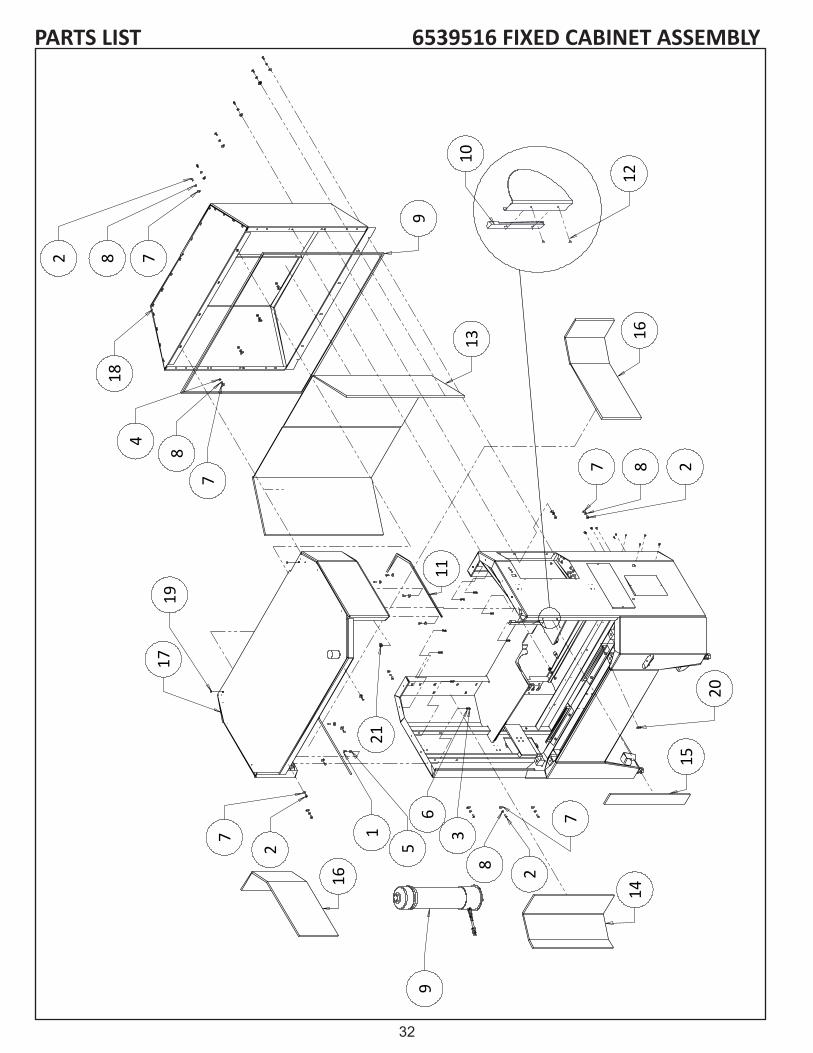
PARTS LIST 6539516 FIXED CABINET ASSEMBLY
14
1528
6
3
2
1
8
4
13
18
17
2 8
911
957
7
7
7
16
16
28
7
12
10
19
20
21

33
6539516 FIXED CABINET ASSEMBLYPARTS LISTDIAGRAM NO. PART NO. DESCRIPTION1........................... B311401 ............... 5/16-18x7/8 HEX HEAD CAP SCREW2........................... B371216 ............... 3/8-16x3/4 BUTTON HEAD CAP SCREW3........................... J311000................ 5/16-18 HEX NUT FULL4........................... J371000................ 3/8-16 HEX NUT5........................... K310001 ...............FLAT WASHER 5/16 SAE6........................... K311501 ...............5/16 LOCKWASHER SPLIT7........................... K370001 ...............FLAT WASHER 3/8 SAE8........................... K371501 ...............3/8 LOCKWASHER SPLIT9........................... 3706045 ...............VACUUM MASTERCRAFT............................. 3706046 ...............VACUUM BAG (MASTERCRAFT 652)............................. 3706067 ...............GREY FILTER INNER BAG............................. 3708874 ...............SIZING ADAPTER10......................... 3707958 ...............MACHINE LIGHT - LED11......................... 3708378 ...............STRIP FOAM .25 THICK12......................... 3708675 ...............RIVET - BLIND .188 DIAMETER13......................... 6529083 ...............FOAM PAD CANOPY BACK WINCH14......................... 6539008 ...............LEFT SIDE FRAME FOAM SHEET15......................... 6539009 ...............RIGHT SIDE FRAME FOAM SHEET16......................... 6539013 ...............TOP CANOPY FOAM SHEET17......................... 6539507 ............... TOP WELDMENT18......................... 6539508 ...............FIXED BACK WELDMENT19......................... 3706250 ...............HOLE PLUG .375 DIAMETER BLACK20......................... 3706224 ...............HOLE PLUG 1.13 DIAMETER21......................... 3706260 ...............GROMMET 1 INCH

34
PARTS LIST 6539517 SLOTTED TOP CABINET ASSEMBLY
D
4
1
27
93
8
5
6
10
9
11
12
13
14
15
21
22
24
23
18
19
20
310
9
25
16
17
35
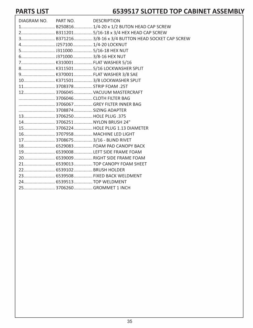
6539517 SLOTTED TOP CABINET ASSEMBLYPARTS LISTDIAGRAM NO. PART NO. DESCRIPTION1........................... B250816 ............... 1/4-20 x 1/2 BUTON HEAD CAP SCREW2........................... B311201 ............... 5/16-18 x 3/4 HEX HEAD CAP SCREW3........................... B371216 ............... 3/8-16 x 3/4 BUTTON HEAD SOCKET CAP SCREW 4........................... J257100................ 1/4-20 LOCKNUT5........................... J311000................ 5/16-18 HEX NUT 6........................... J371000................ 3/8-16 HEX NUT7........................... K310001 ...............FLAT WASHER 5/168........................... K311501 ...............5/16 LOCKWASHER SPLIT9........................... K370001 ...............FLAT WASHER 3/8 SAE10......................... K371501 ...............3/8 LOCKWASHER SPLIT11......................... 3708378 ............... STRIP FOAM .25T 12......................... 3706045 ...............VACUUM MASTERCRAFT............................. 3706046 ...............CLOTH FILTER BAG............................. 3706067 ...............GREY FILTER INNER BAG............................. 3708874 ...............SIZING ADAPTER13......................... 3706250 ...............HOLE PLUG .37514......................... 3706251 ...............NYLON BRUSH 24"15......................... 3706224 ...............HOLE PLUG 1.13 DIAMETER16......................... 3707958 ...............MACHINE LED LIGHT17......................... 3708675 ...............3/16 - BLIND RIVET18......................... 6529083 ...............FOAM PAD CANOPY BACK19......................... 6539008 ............... LEFT SIDE FRAME FOAM20......................... 6539009 ...............RIGHT SIDE FRAME FOAM21......................... 6539013 ...............TOP CANOPY FOAM SHEET22......................... 6539102 ...............BRUSH HOLDER23......................... 6539508 ...............FIXED BACK WELDMENT24......................... 6539513 ............... TOP WELDMENT25......................... 3706260 ...............GROMMET 1 INCH

36
PARTS LIST REAR DOOR OPTION 6539506 CABINET REAR DOORS -653
25
24
43
5361
41
2
31
55
56
1
57
27
59
9
58
17
9
24
5829
39
35
39 36
54
48
47
37
38
44
34
45
21 17
12
31
60
13
60
13
51
28
50
195
726
23
18
2 34
46
46
2
18
3423
8
26
4
1611
13
2
4240
28
52
58
27
25
32
29
20 32
6161
49
99
22
13
3033
6
1415
103
2662

37
PARTS LIST REAR DOOR OPTION 6539506 CABINET REAR DOORS -653DIAGRAM NO. PART NO. DESCRIPTION1.............................. B311013 ................. 5/16-18 x 5/8 BUTTON HEAD SOCKET CAP SCREW2.............................. B250816 ................. 1/4-20 x 1/2 BUTTON HEAD SOCKET CAP SCREW3.............................. B251005 ................. 1/4-20 x 5/8 FLAT HEAD SOCKET CAP SCREW4.............................. B311201 ................. 5/16-18 x 3/4 HEX HEAD CAP SCREW5.............................. B371611 ................. 3/8-16 x 1 SOCKET HEAD CAP SCREW6.............................. B371625 ................. 3/8-16 x 1 FLAT HEAD SOCKET CAP SCREW7.............................. B372416 ................. 3/8-16 x 1-1/2 BUTTON HEAD CAP SCREW8.............................. B373216 ................. 3/8-16 x 2 BUTTON HEAD SOCKET CAP SCREW9.............................. J197100 .................. 10-24 LOCKNUT JAM NYLON INSERT10............................ J251000 .................. 1/4-20 HEX NUT11............................ J257000 .................. 1/4-20 LOCKNUT JAM12............................ J311000 .................. 5/16-18 HEX NUT13............................ J377000 .................. 3/8-16 LOCKNUT JAM14............................ K250001 ................. FLAT WASHER 1/4 SAE15............................ K251501 ................. 1/4 LOCKWASHER SPLIT16............................ K310001 ................. FLAT WASHER 5/16 SAE17............................ K311501 ................. 5/16 LOCKWASHER SPLIT18............................ K370001 ................. FLAT WASHER 3/8 SAE19............................ K371501 ................. 3/8 LOCKWASHER SPLIT20............................ 55476 ..................... DOOR SWITCH BRACKET21............................ 3706045 ................. VACUUM MASTERCRAFT................................ 3706046 ................. CLOTH FILTER BAG................................ 3706067 ................. GREY FILTER INNER BAG22............................ 3706062 ................. 1/4-20 ACORN NUT23............................ 3706063 ................. WIRE ROPE PULLEY 24............................ 3706205 ................. FLUSH MOUNT DOOR25............................ 3706206 ................. 28 IN DRAWER SLIDE26............................ 3706208 ................. WIRE ROPE ASSEMBLY27............................ 3708416 ................. SOFT LATCH SOUTHCO28............................ 3707273 ................. STRAIN RELF .33-.3929............................ 3707908 ................. DOOR SWITCH W/DISCONNECT30............................ 3708036 ................. BALL BRG R6-2RS31............................ 3708379 ................. STRIP FOAM .50 THICK32............................ 3708820 ................. 8-32 x .50 BUTTON HEAD SAFETY SCREW33............................ 3708999 ................. WASHER FLAT .38 x .56 x .03 THICK34............................ 4609049 ................. SPACER .385 ID x .75 OD x .38 LONG35............................ 6539008 ................. LEFT SIDE FRAME36............................ 6539009 ................. RIGHT SIDE FRAME37............................ 6539011 ................. FOAM REAR DOORS 38............................ 6539012 ................. FOAM REAR DOOR SIDE39............................ 6539013 ................. TOP CANOPY FOAM40............................ 6539032 ................. LEFT REAR DOOR RAIL41............................ 6539033 ................. RIGHT REAR DOOR RAIL42............................ 6539034 ................. LEFT REAR DOOR GUIDE43............................ 6539035 ................. RIGHT REAR DOOR GUIDE44............................ 6539036 ................. REAR DOOR TRAP45............................ 6539041 ................. CABLE TOP GAURD46............................ 6539042 ................. CABLE GUARD47............................ 6539044 ................. FOAM REAR DOORS48............................ 6539045 ................. FOAM REAR DOOR SIDE49............................ 6539062 ................. REAR DOOR CORD50............................ 3706052 ................. FOAM SEAL ADHESIVE51............................ 6509269 ................. BRACKET VAC HOSE52............................ 6539504 ................. LEFT REAR DOOR WELDMENT53............................ 6539505 ................. RIGHT REAR DOOR WELDMENT54............................ 6539507 ................. TOP WELDMENT55............................ 3708675 ................. 3/16 - BLIND RIVET56............................ 3707958 ................. MACHINE LIGHT - LED57............................ 6339201 ................. REAR BUMPER58............................ B190811 ................. 10-24 x 1/2 SOCKET HEAD CAP SCREW59............................ 6309038 ................. BRACKET - DOOR60............................ B371216 ................. 3/8-16 x 3/4 BUTTON HEAD CAPSCREW61............................ J167000 .................. 8-32 LOCKNUT JAM NYLON INSERT62............................ J251001 .................. 1/4-28 HEX NUT

38
MODEL 633 -6339520 FRONT DOOR ASSEMBLYPARTS LIST
1
4
56
7
8
8101214
14
14
17
18
19
23
26
27
29
31
33
33
16
34
36
35
37
39
40
41
3
16
42
15
2
12
21
22
3032
5
6
7
1414
38 29
36
35
3
9
11
13
14
16
20
24
25
2734
41

39
MODEL 633 -6339520 FRONT DOOR ASSEMBLYPARTS LIST DIAGRAM NO. PART NO. DESCRIPTION1........................... B230611 ...............M6 x 10 SOCKET HEAD CAP SCREW2........................... B251011 ...............1/4-20 x 5/8 SOCKET HEAD CAP SCREW3........................... B310813 ...............5/16-18 x 1/2 BUTTON HEAD SOCKET CAP SCREW4........................... B311016 ...............5/16-18 x 5/8 BUTTON HEAD SOCKET CAP SCREW5........................... B311213 ...............5/16-18 x .75 BUTTON HEAD SOCKET CAP SCREW6........................... B371216 ...............3/8-16 x 3/4 BUTTON HEAD SOCKET CAP SCREW7........................... B372811 ...............3/8-16 x 1-3/4 SOCKET HEAD CAP SCREW FULL THD8........................... B374811 ...............3/8-16 x 1-3/4 SOCKET HEAD CAP SCREW FULL THD9........................... J167000................8-32 LOCKNUT JAM NYLON INSERT10......................... J252000................1/4-20 HEX JAM NUT11......................... J311000................5/16-18 HEX NUT FULL12......................... J317100................5/16-18 LOCKNUT FULL NYLON INST13......................... J372000................3/8-16 HEX JAM NUT14......................... J377000................3/8-16 LOCKNUT JAM NYLON INSERT15......................... K251501 ...............1/4 LOCKWASHER SPLIT16......................... K311501 ...............5/16 LOCKWASHER SPLIT17......................... 3706039 ...............HOLE PLUG .687 DIA. x .125 THK 18......................... 3706186 ...............WINDOW GASKET19......................... 3706215 ...............LEDGE HANDLE20......................... 3706217 ...............SHOULDER BOLT .5 x 2.5L21......................... 3706218 ...............SHOULDER BOLT .38 x 2.5L22......................... 3706226 ...............COMP. SPRING 3 L x .72 OD x .085 DIA WIRE23......................... 3706232 ...............3/8 16 x 4.5" SOCKET HEAD CAP SCREW FULL THREAD24......................... 3707908 ...............DOOR SWITCH W/DISCONNECT25......................... 3708820 ...............8-32 x .50 BUTTON HD SAFETY SCREW26......................... 3708889 ...............SEAL FOAM .50 HIGH27......................... 3709027 ...............THRUST WASHER .507 x .917 x .062 T28......................... 3709304 ...............THRUST WASHER .375 x .812 x .032 T29......................... 4609063 ...............SPACER .385 x .625 x .25 L30......................... 6339039 ...............DOOR PIVOT BRACKET31......................... 6339050 ...............ACCU-PRO 633 DECAL32......................... 6339051 ...............DOOR PIVOT ARM MACHINED ecp33......................... 6339056 ...............WINDOW 18.5 x 26 (633)34......................... 6339057 ...............DOOR CENTER PLATE35......................... 6539086 ...............UPPER DOOR PIVOT ARM36......................... 6339189 ...............DOOR UPPER ARM BRACKET37......................... 6339201 ...............REAR BUMPER38......................... 6339202 ...............UPPER DOOR PIVOT39......................... 6339521 ...............633 DOOR WELDMENT RH40......................... 6339522 ...............633 DOOR WELDMENT LH41......................... 6339524 ...............DOOR PIVOT ARM WELDMENT42......................... 6539088 ...............DOOR SHIPPING BRACKET

40
MODEL 633- 6339545 REAR DOOR ASSEMBLYPARTS LIST
3
4
10
10
18
18
26
26
39
43
55
63
60
27
27
57
66
8
6625
4
13
20
16
26
12
17
26
30
44
46
47
4858
61
62
4
2425
42
52
41
1859
45
22
2
23
4
33
15
1
23
14
5
21
24
25 31
32
3437
38
50
54
5
25
36
28
35
51
27 9
11
53
28 35
28
27
19
53
6465
67
23
15
23
67
56
3
18
4
33
45

41
MODEL 633- 6339545 REAR DOOR ASSEMBLYPARTS LIST DIAGRAM NO. ..........PART NO. DESCRIPTION1............................... B190411 .................. 10-24 x 1/4 SOCKET HEAD CAP SCREW2............................... B190613 .................. 10-24 x 3/8 BUTTON HEAD SOCKET SCREW CAP3............................... B250816 .................. 1/4-20 x 1/2 BUTTON HEAD SOCKET SCREW CAP4............................... B251016 .................. 1/4-20 x 5/8 BUTTON HEAD SOCKET SCREW CAP5............................... B251216 .................. 1/4-20 x 3/4 BUTTON HEAD SOCKET SCREW CAP6............................... B310813 .................. 5/16-18 x 1/2 BUTTON HEAD SOCKET SCREW CAP7............................... B370801 .................. 3/8-16 x 1/2 HEX HEAD CAP SCREW8............................... B370816 .................. 3/8-16 x 1/2 BUTTON HEAD SOCKET SCREW CAP9............................... B372001 .................. 3/8-16 x 1-1/4 HEX HEAD CAP SCREW10............................. B372016 .................. 3/8-16 x 1.25 BUTTON HEAD SOCKET SCREW CAP11............................. B372401 .................. 3/8-16 x 1-1/2 HEX HEAD CAP SCREW12............................. B372416 .................. 3/8-16 x 1-1/2 BUTTON HEAD SOCKET SCREW CAP13............................. H371202 .................. ROLL PIN .375 D x .7514............................. J167000 ................... 8-32 LOCKNUT JAM 15............................. J191000 ................... 10-24 HEX NUT16............................. J252000 ................... 1/4-20 HEX JAM NUT17............................. J257000 ................... 1/4-20 LOCKNUT JAM18............................. J257100 ................... 1/4-20 LOCKNUT19............................. J371000 ................... 3/8-16 HEX NUT20............................. J377000 ................... 3/8-16 LOCKNUT JAM21............................. J627100 ................... 5/8-11 LOCKNUT 22............................. K190001 .................. FLAT WASHER #10 SAE23............................. K191501 .................. #10 LOCKWASHER SPLIT24............................. K250001 .................. FLAT WASHER 1/4 SAE25............................. K251501 .................. 1/4 LOCKWASHER SPLIT26............................. K370001 .................. FLAT WASHER 3/8 SAE27............................. K371501 .................. 3/8 LOCKWASHER SPLIT28............................. 09054 ....................... FLAT WASHER .387 x .625 x .06529............................. 55492 ....................... DOOR SAFETY SWITCH PLATE30............................. 80406 ....................... FLAT WASHER .27 ID x .50 x .0631............................. 80418 ....................... STUD GAS SPRING32............................. 80421 ....................... RETAINING CLIP GAS33............................. 3249153................... FLAT WASHER .252 x .375 x .01834............................. 3706032................... BALL BEARING R10 W/OIL35............................. 3706097................... PULLEY 1.75 OD x .37 ID36............................. 3706098................... PULLEY 1.5 OD x .25 ID37............................. 3706099................... CLEVIS ROD END M838............................. 3706100................... GAS SPRING 202# 3.9 STROKE39............................. 3706212................... CABLE ASSY REAR DOOOR40............................. 3707029................... STRAIN RELF LIQUID TIGHT41............................. 3707908................... DOOR SWITCH WITH DISCONNECT42............................. 3708820................... 8-32 x .50 BUTTON HEAD SAFETY SCREW43............................. 3708869................... SPRING HINGE44............................. 3708998................... WAVE SPRING .35 ID45............................. 3709597................... BALL BEARING46............................. 6329131................... CATCH47............................. 6329133................... CATCH PIN48............................. 6329136................... REAR SLIDE SPACER49............................. 6329137................... REAR SLIDING DOOR50............................. 6329163................... REAR DOOR ARM51............................. 6329164................... PULLEY BLOCK52............................. 6329165................... DOOR SWITCH BRACKET53............................. 6329166................... CABLE GUIDE54............................. 6329167................... BEARING BLOCK55............................. 6329172................... REAR DOOR INNER SLIDE56............................. 6329174................... REAR DOOR LIFT HANDLE57............................. 6329175................... REAR DOOR STIFFENER58............................. 6329179................... REAR DOOR OUTER PLATE59............................. 6329180................... DOOR STOP BLOCK60............................. 6329181................... HINGED WALKER PANE61............................. 6329182................... DOOR STOP SPACER PLATE62............................. 6329183................... DOOR CATCH BRACKET63............................. 6339168................... REAR DOOR SLIDE UP64............................. 6339169................... REAR DOOR CABLE BRACKET65............................. 6339170................... CABLE CLAMP BLOCK66............................. 6339171................... DOOR STOP BLOCK67............................. B190813 .................. 10-24 x 1/2 BUTTON HEAD SOCKET CAP SCREW

42
PARTS LIST 6332901 COMMON ASSEMBLY
1
3
41
3843
35
50
4
3019
51
45
46 7
50
49
40
6
26
482
5
47
4234
36
46
C
11
8
52
24
13
39
1911
14
4433
8
11

43
PARTS LIST 6332901 COMMON ASSEMBLYDIAGRAM NO. PART NO. DESCRIPTION1........................... 6339516 ...............TRAVERSE BASE ASSEMBLY2........................... 6339537 ...............CROSS SLIDE SUB ASSSEMBLY3........................... 6339505 ...............SPIN DRIVE ASSEMBLY4........................... 6339530 ...............FRONT TOOLING ASSEMBLY5........................... 6339534 ...............REAR TOOLING ASSEMBLY6........................... 6339538 ...............POSITION GAUGE ASSEMBLY7........................... 6339544 ............... FRAME WELDMENT PAINT8........................... B130412 ............... 6-32 x 1/4 PAN HEAD MACHINE SCREW9........................... B190634 ............... 10-32 x 3/8 BUTTON HEAD SOCKET CAP SCREW 10......................... B250616 ............... 1/4-20 x 3/8 BUTTON HEAD SOCKET CAP SCREW 11......................... B250816 ............... 1/4-20 x 1/2 BUTTON HEAD SOCKET CAP SCREW 12......................... B250819 ............... 1/4-20 x 1/2 TRUSS HEAD MACHINE SCREW13......................... B251016 ............... 1/4-20 x 5/8 BUTTON HEAD SOCKET CAP SCREW 14......................... B310813 ............... 5/16-18 x 1/2 BUTTON HEAD SOCKET CAP SCREW 15......................... B311013 ............... 5/16-18 x 5/8 BUTTON HEAD SOCKET CAP SCREW 16......................... B311613 ............... 5/16-18 x 1.0 BUTTON HEAD SOCKET CAP SCREW 17......................... B314811 ............... 5/16-18 x 3 SOCKET HEAD CAP SCREW FULL18......................... B371211 ............... 3/8-16 x 3/4 SOCKET HEAD CAP SCREW19......................... B502811 ............... 1/2-13 x 1-3/4 SOCKET HEAD CAP SCREW20......................... B503211 ............... 1/2-13 x 2 SOCKET HEAD CAP SCREW21......................... B504801 ............... 1/2-13 x 3 HEX HEAD CAP SCREW22......................... H371602 ..............ROLL PIN .375 D x 1.023......................... J137000................ 6-32 LOCKNUT JAM NUT24......................... J257100................ 1/4-20 LOCKNUT FULL25......................... J317100................ 5/16-18 LOCKNUT 26......................... J507100................ 1/2-13 LOCKNUT FULL27......................... K191501 ...............#10 LOCKWASHER SPLIT28......................... K251501 ...............1/4 LOCKWASHER SPLIT29......................... K310001 ...............FLAT WASHER 5/16 SPLIT30......................... K311501 ...............5/16 LOCKWASHER SPLIT31......................... K371501 ...............3/8 LOCKWASHER SPLIT32......................... K501501 ...............1/2 LOCKWASHER SPLIT33......................... 3706193 ...............GRAB CATCH - METAL34......................... 3706219 ............... .25"PLASTIC WASHER35......................... 3706220 ...............WING HANDLE CAM LATCH36......................... 3708543 ...............SHOULDER BOLT .313 DIA x .32 LG37......................... 3708908 ...............ADJUSTABLE HANDLE 3/8-16 x .78 LG38......................... 6059030 ...............HINGE - FRONT END39......................... 6329070 ...............HINGE PAINTED40......................... 6339083 ............... ELECTRICAL PANEL

44
60
5
23 5658
15
2676
47
77
37
39
53
18
6
618
27
48
15
41
7823
9
10
2374
57
50
52
22
23
8
27
30
24
12
49
233
711
2
21
1
2145
62
42
51
45
32
121
2013
24
53
19
81
46 23
7561
79/80
82
23
54
33
4
23
22
55
63
7270
71
16
43
4435
31
29
443835
14
25
4017
59
28
69
65
66
64
66
69 73
6867
PARTS LIST 6339516 TRAVERSE BASE
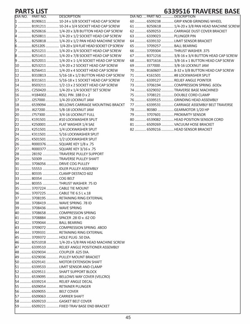
45
6339516 TRAVERSE BASEPARTS LISTDIA NO. PART NO. DESCRIPTION1 .............. B190611 .............10-24 x 3/8 SOCKET HEAD CAP SCREW2 .............. B191211 .............10-24 x 3/4 SOCKET HEAD CAP SCREW3 .............. B250616 .............1/4-20 x 3/8 BUTTON HEAD CAP SCREW4 .............. B250811 .............1/4-20 x 1/2 SOCKET HEAD CAP SCREW5 .............. B250818 .............1/4-20 x 1/2 PAN HEAD MACHINE SCREW6 .................B251205 ................ 1/4-20 x 3/4 FLAT HEAD SOCKET CP SCREW7 .............. B251211 .............1/4-20 x 3/4 SOCKET HEAD CAP SCREW8 .............. B251411 .............1/4-20 x 7/8 SOCKET HEAD CAP SCREW9 .............. B252011 .............1/4-20 x 1-1/4 SOCKET HEAD CAP SCREW10 ............ B253211 .............1/4-20 x 2 SOCKET HEAD CAP SCREW11 ............ B256411 .............1/4-20 x 4 SOCKET HEAD CAP SCREW12 ............ B310813 .............5/16-18 x 1/2 BUTTON HEAD CAP SCREW13 ............ B311611 .............5/16-18 x 1 SOCKET HEAD CAP SCREW14 ............ B503211 .............1/2-13 x 2 SOCKET HEAD CAP SCREW15 ............ C250420 .............1/4-20 x 1/4 SOCKET SET SCREW16 ............ H184002 .............ROLL PIN .188 D x 217 ............ J257000 ..............1/4-20 LOCKNUT JAM18 ............ 6539094 .............BELLOWS CARRIAGE MOUNTING BRACKT19 ............ J627200 ..............5/8-18 LOCKNUT JAM20 ............ J757300 ..............3/4-16 LOCKNUT FULL21 ............ K191501 .............#10 LOCKWASHER SPLIT22 ............ K250001 .............FLAT WASHER 1/4 SAE23 ............ K251501 .............1/4 LOCKWASHER SPLIT24 ............ K311501 .............5/16 LOCKWASHER SPLIT25 ............ K501501 .............1/2 LOCKWASHER SPLIT26 ............ R000376 .............SQUARE KEY 1/8 x .7527 ............ R000377 .............SQUARE KEY 3/16 x .7528 ............ 28192 .................TRAVERSE PULLEY SUPPORT29 ............ 50309 .................TRAVERSE PULLEY SHAFT30 ............ 3706056 .............DRIVE COG PULLEY 31 ............ 55553 ................. IDLER PULLEY ASSEMBLY32 ............ 80335 .................CLAMP DESTACO 60233 ............ 80354 .................COG BELT 34 ............ 80355 .................THRUST WASHER .75 ID35 ............ 3707224 .............CABLE TIE MOUNT36 ............ 3707225 .............CABLE TIE 6.5 L x.1837 ............ 3708195 .............RETAINING RING EXTERNAL38 ............ 3708419 .............WAVE SPRING .78 ID39 ............ 3708436 .............WAVE SPRING 40 ............ 3708658 .............COMPRESSION SPRING41 ............ 3708884 .............SPACER .28 ID x .62 OD42 ............ 3709044 .............BALL BEARING43 ............ 3709072 .............COMPRESSION SPRING .48OD44 ............ 3709331 .............RETAINING RING EXTERNAL45 ............ 3709372 .............HOLE PLUG .50 DIA.46 ............ B251018 .............1/4-20 x 5/8 PAN HEAD MACHINE SCREW47 ............ 6339510 .............RELIEF ANGLE POSITIONER ASSEMBLY48 ............ 6329034 .............COUPLER .625 DIA.49 ............ 6329036 .............PULLEY MOUNT BRACKET50 ............ 6329141 .............MOTOR EXTENSION SHAFT51 ............ 6339533 .............LIMIT SENSOR AND CLAMP52 ............ 6329511 .............SHAFT SUPPORT BLOCK53 ............ 6539095 .............BELLOWS WAY COVER (VELCRO)54 ............ 6339214 .............RELIEF ANGLE DECAL55 ............ 6509054 .............RETAINER PLUNGER56 ............ 6509055 .............BELT COVER57 ............ 6509063 .............CARRIER SHAFT58 ............ 6509210 .............GASKET BELT COVER59 ............ 6509221 .............FIXED TRAV BASE END BRACKET
DIA NO. ... PART NO. ............DESCRIPTION 60 ............ 6509238 .............GRIP KNOB GRINDING WHEEL61 ............ B250618 .............1/4-20 x 3/8 PAN HEAD MACHINE SCREW62 ............ 6509253 .............CARRIAGE DUST COVER BRACKET63 ............ 6339023 .............PLUNGER PIN64 ............ 6339132 .............LIMIT SENSOR BRACKET65 ............ 3709257 .............BALL BEARING66 ............ 3709304 .............THRUST WASHER .37567 ............ B371216 .............3/8-16 x 3/4 BUTTON HEAD CAP SCREW68 ............ B371616 .............3/8-16 x 1 BUTTON HEAD CAP SCREW69 ............ J377000 ..............3/8-16 LOCKNUT JAM70 ............ B160607 .............8-32 x 3/8 BUTTON HEAD CAP SCREW71 ............ K161501 .............#8 LOCKWASHER SPLIT72 ............ 6339127 .............RELIEF ANGLE POINTER73 ............ 3706194 .............COMPRESSION SPRING .6ODx74 ............ 6329032 .............TRAVERSE BASE MACHINED75 ............ 3708121 .............DOUBLE CORD CLAMP76 ............ 6339515 .............GRINDING HEAD ASSEMBLY77 ............ 6339531 .............CARRIAGE ASSEMBLY BELT TRAVERSE78 ............ 80380 .................GEARMOTOR 1/20 HP 79 ............ 3707601 .............PROXIMITY SENSOR80 ............ 6539082 .............HEAD POSITION SENSOR CORD81 ............ 6509269 .............VACUUM HOSE BRACKET82 ............ 6509216 .............HEAD SENSOR BRACKET

46
PARTS LIST 6339531 CARRIAGE ASSEMBLY
24
2
18
10
20
16
17
1
18
9
7
22
234
16
3
21
11
5
1114
198
12
13 15
1
78
6
17
11
10

47
PARTS LIST 6339531 CARRIAGE ASSEMBLYDIAGRAM NO. PART NO. DESCRIPTION1........................... B130412 ............... 6-32 x 1/4 PAN HEAD MACHINE SCREW2........................... B190509 ............... 10-24 x 5/16 PAN HEAD MACHINE SCREW3........................... B191013 ............... 10-24 x 5/8 BUTTON HEAD SOCKET CAP SCREW4........................... B250616 ............... 1/4-20 x 3/8 BUTTON HEAD SOCKET CAP SCREW5........................... B252016 ............... 1/4-20 x 1-1/4 BUTTON HEAD SOCKET CAP SCREW6........................... B253216 ............... 1/4-20 x 2 BUTTON HEAD SOCKET CAP SCREW7........................... J137000................ 6-32 LOCKNUT JAM NUT8........................... J252000................ 1/4-20 HEX JAM NUT9........................... J887300................ 7/8-14 LOCKNUT 10......................... K191501 ...............#10 LOCKWASHER SPLIT11......................... K251501 ...............1/4 LOCKWASHER SPLIT12......................... 28187 ................... BLOCK TRAVERSE CLAMP13......................... 28188 ................... SPACER TRAVERSE CLAMP14......................... 28189 ................... BLOCK CLAMP SUPPORT15......................... 50310 ................... TIP BELT CLAMP16......................... 3706193 ...............GRAB CATCH - METAL17......................... 3708184 ...............RETAINING RING INTERNAL18......................... 3708186 ...............BALL BEARING DOUBLE ROW 519......................... 6329040 ...............TRAVERSE CLAMP MACHINED20......................... 6329058 ...............CARRIAGE BASE BELT21......................... 6339130 ...............CATCH BRACKET22......................... 6339532 ...............DUST DOOR WELDMENT23......................... 6339559 ...............PIN PLATE WELDMENT24......................... 6509023 ...............GRINDING HEAD PIVOT SHAFT
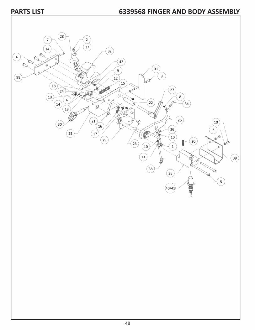
48
PARTS LIST 6339568 FINGER AND BODY ASSEMBLY
728
2
3732
9
1215
31
22
3
27
8
34
29
36
10
26
35
5
1
11
38
23
17
1621
25
30
1914
1324
33
18
4
14
20
42
10
6
40/41
10
2
39
6/17/2016 7:59 AM 6339510.SLDDRW

49
PARTS LIST 6339568 FINGER AND BODY ASSEMBLYDIAGRAM NO. PART NO. DESCRIPTION1........................... B190631 ............... 10-32 x 3/8 SOCKET HEAD CAP SCREW2........................... B190634 ............... 10-32 x 3/8 BUTTON HEAD SOCKET CAP SCREW3........................... B251016 ............... 1/4-20 x 5/8 BUTTON HEAD SOCKET CAP SCREW4........................... B251216 ............... 1/4-20 x 3/4 BUTTON HEAD SOCKET CAP SCREW5........................... B254811 ............... 1/4-20 x 3 SOCKET HEAD CAP SCREW6........................... C160420 ...............8-32 x 1/4 SOCKET SET SCREW CUP POINT7........................... C190460 ...............SOCKET SET SCREW 10-32X1/48........................... C190467 ...............10-32 x 1/4 SOCKET SET SCREW NYLON9........................... C250427 ...............1/4-20 x 1/4 NYLON10......................... K191501 ...............#10 LOCKWASHER SPLIT11......................... J191100................ 10-32 HEX NUT12......................... J197000................ 10-24 LOCKNUT JAM13......................... J377200................ 3/8-24 LOCKNUT JAM14......................... 3579284 ...............NYLON PLUG 1/8 DIA15......................... 3706170 ...............COMPRESSION SPRING .42 OD x .31 ID 16......................... 3706171 ...............COMPRESSION SPRING .42 OD x .33 ID17......................... 3706172 ...............1/4-20 x 3/8 SET SCREW18......................... 3706187 ...............WAVE SPRING .2 ID19......................... 3706188 ...............WAVE SPRING .24 ID20......................... 3708107 ...............COMPRESSION SPRING .24 OD21......................... 3708999 ...............WASHER FLAT .376 x .563 x .0322......................... 6339014 ...............SPACER .5 OD x .33 ID 23......................... 6339016 ............... FINGER STOP POSITION24......................... 6339017 ...............PIN BLOCK25......................... 6339020 ............... FINGER SLIDE BASE26......................... 6339507 ............... INDEX FINGER ASSEMBLY27......................... 6339508 ...............RELIEF ADJUSTER LOCK HANDLE28......................... 6339569 ...............RELIEF ANGLE POSITIONER KNOB ASSEMBLY29......................... 6339511 ...............FINGER STOP PLATE ASSEMBLY30......................... 6339512 ...............FINGER STOP ADJUSTMENT KNOB31......................... 6339548 ...............FIXED FINGER ASSEMBLY32......................... 6339549 ...............FINGER SUPPORT ROTATE ASSEMBLY33......................... 6339547 ...............CLAMP PLATE FOR RELIEF ASSEMBLY34......................... 6509007 ............... INDEX STOP PIN35......................... 6509008 ............... INDEX SENSOR BLOCK36......................... 6509239 ...............ANTI ROTATE PLATE 37......................... 6509358 ............... STOP PLATE 38......................... 6509501 ...............TEE KNOB ASSY 10-32 x 3.039......................... 6509230 ............... INDEX SENSOR GUARD40......................... 3707601 ...............PROXIMITY SENSOR41......................... 6539083 ............... FINGER POSITION SENSOR CORD42......................... 3709705 ...............NYLON BALL 5/32 DIA.

50
PARTS LIST 6339515 GRINDING HEAD
1
2
3
3
4
5
6
7
8
9
10
10
12
11
16
14
15
17
19
2018
13
21
22
23
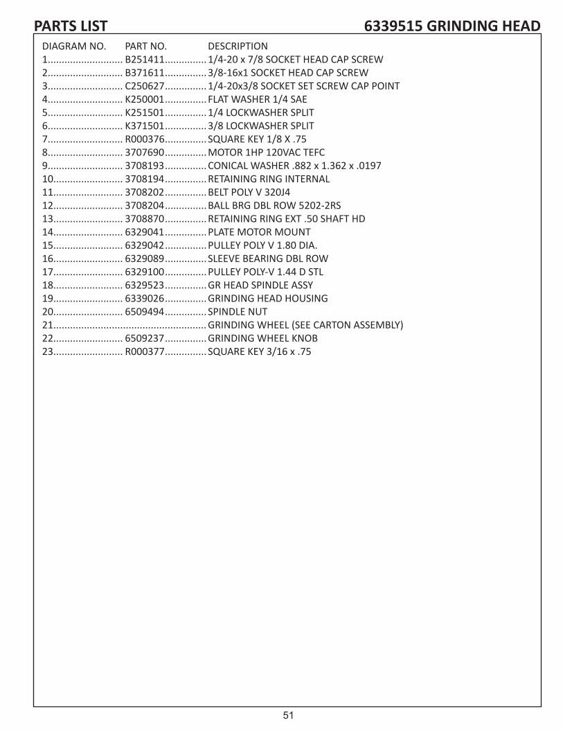
51
6339515 GRINDING HEADPARTS LISTDIAGRAM NO. PART NO. DESCRIPTION1........................... B251411 ............... 1/4-20 x 7/8 SOCKET HEAD CAP SCREW2........................... B371611 ............... 3/8-16x1 SOCKET HEAD CAP SCREW3........................... C250627 ...............1/4-20x3/8 SOCKET SET SCREW CAP POINT4........................... K250001 ...............FLAT WASHER 1/4 SAE5........................... K251501 ...............1/4 LOCKWASHER SPLIT6........................... K371501 ...............3/8 LOCKWASHER SPLIT7........................... R000376 ............... SQUARE KEY 1/8 X .758........................... 3707690 ...............MOTOR 1HP 120VAC TEFC9........................... 3708193 ...............CONICAL WASHER .882 x 1.362 x .019710......................... 3708194 ...............RETAINING RING INTERNAL11......................... 3708202 ...............BELT POLY V 320J412......................... 3708204 ...............BALL BRG DBL ROW 5202-2RS13......................... 3708870 ...............RETAINING RING EXT .50 SHAFT HD14......................... 6329041 ...............PLATE MOTOR MOUNT15......................... 6329042 ...............PULLEY POLY V 1.80 DIA.16......................... 6329089 ............... SLEEVE BEARING DBL ROW17......................... 6329100 ...............PULLEY POLY-V 1.44 D STL18......................... 6329523 ...............GR HEAD SPINDLE ASSY19......................... 6339026 ...............GRINDING HEAD HOUSING20......................... 6509494 ............... SPINDLE NUT21....................................................... GRINDING WHEEL (SEE CARTON ASSEMBLY)22......................... 6509237 ...............GRINDING WHEEL KNOB23......................... R000377 ............... SQUARE KEY 3/16 x .75

52
PARTS LIST 6339537 CROSS SLIDE
6
31
15
1
11
21
10
29
16
5
22
25
27
20
4
28
23
34
32
24
8
13
9
3014
12
2
3
17
26
35
19
13
33
23
276
15
18
22
24
13
9
35
26
10
1816
5
2221
7
12
22

53
PARTS LIST 6339537 CROSS SLIDEDIAGRAM NO. PART NO. DESCRIPTION1........................... B160807 ............... 8-32 x 1/2 BUTTON HEAD SOCKET CAP SCREW 2........................... B250816 ............... 1/4-20 x 1/2 BUTTON HEAD SOCKET CAP SCREW 3........................... B252016 ............... 1/4-20 x 1-1/4 BUTTON HEAD SOCKET CAP SCREW 4........................... B372011 ............... 3/8-16 x 1-1/4 SOCKET HEAD CAP SCREW5........................... H371602 ..............ROLL PIN .375 D x 1.06........................... C311220 ...............5/16-1 8 x 3/4 SOCKET SET SCREW CUP POINT 7........................... J257000................ 1/4-20 LOCKNUT JAM8........................... J371000................ 3/8-16 HEX NUT9........................... J377000................ 3/8-16 LOCKNUT JAM10......................... K161501 ...............#8 LOCKWASHER SPLIT11......................... K251501 ...............1/4 LOCKWASHER SPLIT12......................... K371501 ...............3/8 LOCKWASHER SPLIT13......................... 3109027 ...............SPACER .281 IDx.50 OD14......................... 3579109 ...............NYLON PLUG 3/16 DI15......................... 3708148 ...............HANDWHEEL 4.5 DIA .16......................... 3708581 ...............DIAL INDICATOR 17......................... 3708665 ...............FLAT WASHER .41 x 1.18......................... 3708705 ...............ADJUSTABLE HANDLE 5/16-1819......................... 3708706 ...............ADJUSTABLE HANDLE 5/16-1820......................... 3709062 ...............CONICAL WASHER .38 x .75 x .035 T21......................... 3709304 ...............THRUST WASHER .375 x .812 x .032 T22......................... 3969065 ...............SPACER .406 ID x.75 OD23......................... 6009035 ...............SHAFT LOCKING STUD24......................... 6009082 ............... SUPPORT CROSS SLIDE25......................... 6009095 ...............SHAFT SLIDE26......................... 6309113 ...............SHAFT LOCKING STUD27......................... 6309114 ...............DECAL ORANGE28......................... 6309115 ...............DECAL GREY29......................... 6339027 ...............DIAL INDICATOR MOUNT30......................... 6339028 ...............DIAL INDICATOR STORE31......................... 6509011 ...............CROSS SLIDE32......................... 6509015 ............... SUPPORT CROSS SLIDE33......................... 6509010 ...............ADJUSTER TRAVEL BRACKET34......................... 6509390 ...............ADJUSTING SHAFT

54
6339505 SPIN DRIVE ASSEMBLYPARTS LIST
25 15
19
11
23
3
1
21
22
14
5
7
8
18
17
4
2
9
13
10
16
20
26
6
24
28
819
15
19
4
12
12
12
20
13
27

55
6339505 SPIN DRIVE ASSEMBLYPARTS LISTDIAGRAM NO. PART NO. DESCRIPTION1........................... B190613 ............... 10-24 x 3/8 BUTTON HEAD SOCKET CAP SCREW2........................... B200611 ............... M5-.8 x 10 SOCKET HEAD CAP SCREW METRIC3........................... B253216 ............... 1/4-20 x 2 BUTTON HEAD SOCKET CAP SCREW4........................... C190420 ...............10-24 x 1/4 SOCKET SET SCREW CAP POINT5........................... E253200 ...............CARRB 1/4-20 x 2.006........................... H182002 ..............PIN - ROLL .188 D x 1.25 L7........................... J257000................ 1/4-20 LOCKNUT JAM NYLON INSERT8........................... K191501 ...............#10 LOCKWASHER SPLIT9........................... 3109027 ...............SPACER .281 ID x .50 OD x. 50 L STEEL10......................... 3706138 ...............GAS SPRING 130# 1.97" STROKE11......................... 3706255 ...............GAS SPRING 30# 1.97" STROKE12......................... 3706155 ...............STEEL CLEVIS ROD END FOR M6 x 113......................... 3706156 ...............CLEVIS PIN 3/16 x 1-3/4 L14......................... 3706157 ...............CLEVIS PIN 3/16 x 1-1/2 L15......................... 3706158 ...............KNOB T 1.5 1/4-20 F16......................... 3706159 ...............5/16-18 x .5" BUTTON HEAD SOCKET CAP SCREW W/PATCH17......................... 3706165 ...............MOTOR DRIVE ADAPTER 12MM-1/2 SQUARE18......................... 3706166 ...............8-32 BALL NOSE SPRING PLUNGER19......................... 3708861 ...............CONICAL WASHER .258 x .688 x .04820......................... 3709062 ...............CONICAL WASHER .382 x .75 x .035 T21......................... 6339005 ............... SPIN DRIVE UPPER ARM22......................... 6339006 ...............SPIN MOTOR PIVOT BLOCK23......................... 6339012 ...............SPACER .26 ID x .5 OD x 1.0 L24......................... 6339501 ............... SPIN DRIVE LOWER ARM WELDMENT25......................... 6339503 ...............MOTOR HOUSING END CAP26......................... 6339504 ...............SPIN DRIVE BASE PIVOT BLOCK ASSEMBLY27......................... 6339564 ...............MOTOR HOUSING WELDMENT W/ SLOT28......................... 6339565 ...............SPIN MOTOR ASSEMBLY 1.9A
NOT SHOWN ........ 3707255 ...............CABLE TIE 4 L x.10 W x.038 T

56
PARTS LIST 6339530 FRONT TOOLING
14
27
11
8
331
28
32
10
31
2
7
4125
5
34
42
18
22
35
36
39
23
38
13
6
37
4
26
12
30
17
2029
21
15
40
31
2
7
19
3
10
9
16
24

57
PARTS LIST 6339530 FRONT TOOLINGDIAGRAM NO. PART NO. DESCRIPTION1........................... B251416 ............... 1/4-20 x 7/8 BUTTON HEAD SOCKET CAP SCREW2........................... B251611 ............... 1/4-20 x 1 SOCKET HEAD CAP SCREW3........................... B252416 ............... 1/4-20 x 1-1/2 BUTTON HEAD SOCKET CAP SCREW4........................... B311013 ............... 5/16-18 x 5/8 BUTTON HEAD SOCKET CAP SCREW5........................... B371625 ............... 3/8-16 x 1 FLAT HEAD SOCKET CAP SCREW6........................... B371611 ............... 3/8-16 x 1 SOCKET HEAD CAP SCREW7........................... C250620 ...............1/4-20 x 3/8 SOCKET SET SCREW CAP POINT8........................... H251202 ..............ROLL PIN .25 D x .75 L9........................... J377000................ 3/8-16 LOCKNUT JAM NYLON INSERT10......................... K251501 ...............1/4 LOCKWASHER SPLIT11......................... K310001 ...............FLAT WASHER 5/16 STEEL12......................... K311501 ...............5/16 LOCKWASHER SPLIT13......................... K371501 ...............3/8 LOCKWASHER SPLIT14......................... 09853 ................... KNOB - 4 PRONG 1/2-13F15......................... 17119 ................... STUD - THD 1/2-13 x 6.5 LG16......................... 3679096 ...............SPACER .281IDx.625 OD x .75 L17......................... 3706189 ...............BRG - DU SLEEVE 1/2 ID x 3/4 LG18......................... 3706190 ...............RATCHET WRENCH .625” HEX19......................... 3706191 ...............BRG - OILITE FLANGE .375 x .5 x .2520......................... 3706192 ...............1/2”OD x 8” LG SHAFT21......................... 3706203 ...............SPRING COMPRESSION .72 OD x 2 LG22......................... 3706204 ...............RETAINING RING EXTERNAL 5103-62 LOW CLEARANCE FOR 5/8” SHAFT23......................... 3706234 ...............BRG - OILITE SLEEVE .62 x.73 x .5024......................... 3706235 ...............DAMPER - 10MM SHAFT25......................... 3708094 ...............ADJ HANDLE 5/16-18 x 1.25 LG26......................... 3708908 ...............ADJ HANDLE 3/8-16 x.78 LG27......................... 6009031 ...............SPACER .386 ID x.50 OD x .56 L STEEL28......................... 6339095 ............... FRONT TOOLING TOP PLATE29......................... 6339099 ............... SPRING GUIDE30......................... 6339100 ...............SLIDE CLAMP BLOCK31......................... 6339103 ...............SHAFT SUPPORT BLOCK32......................... 6339104 ............... TOOLING PLATE LONG BRACE33......................... 6339105 ...............TOOLING PLATE SHORT BRACE34......................... 6339109 ............... FRONT TOOLING MOUNT PLATE35......................... 6339111 ...............FRONT TOOLING RIGHT SIDE PLATE36......................... 6339112 ............... FRONT TOOLING LEFT SIDE PLATE37......................... 6339113 ...............LOCK PLATE38......................... 6339114 ...............TOOLING LOCK BLOCK39......................... 6339207 ............... FRONT TOOLING OUTER PLATE40......................... 6339527 ............... FORNT CLAMP WELDMENT41......................... 6339561 ...............FRONT ROLLER MOUNT MACHINED42......................... 6339562 ...............PINION SHAFT WELDMENT
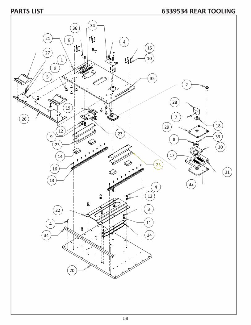
58
6339534 REAR TOOLINGPARTS LIST
154
35
10
6
27
26
1
9
9
23
14
13
16
34
20
24
3
11
4
12
19
5
22
21
34
4
2312
36
25
2
28
1829
8
30
31
32
17
7
33

59
6339534 REAR TOOLINGPARTS LISTDIAGRAM NO. PART NO. DESCRIPTION1........................... B250616 ............... 1/4-20 x 3/8 FLAT HEAD SOCKET CAP SCREW2........................... B250816 ............... 1/4-20 x 1/2 FLAT HEAD SOCKET CAP SCREW3........................... B251216 ............... 1/4-20 x 3/4 FLAT HEAD SOCKET CAP SCREW4........................... B251416 ............... 1/4-20 x 7/8 FLAT HEAD SOCKET CAP SCREW5........................... B311013 ............... 5/16-18 x 5/8 FLAT HEAD SOCKET CAP SCREW6........................... B311413 ............... 5/16-18 x 7/8 BUTTON HEAD SOCKET CAP SCREW7........................... C190320 ...............10-24 x 3/16 SOCKET SET SCREW CAP POINT8........................... H180901 ..............PIN - DOWEL .188 D x9........................... J311000................ 5/16-18 HEX NUT FULL10......................... K121501 ...............#5 LOCKWASHER SPLIT11......................... K251501 ...............1/4 LOCKWASHER SPLIT12......................... K311501 ...............5/16 LOCKWASHER SPLIT13......................... 3706195 ...............BEARING RAIL - 15M14......................... 3706196 ............... LINEAR BEARING 15M15......................... 3706197 ...............M3-.5 X 20MM SOCKET HEAD CAP SCREW16......................... 3706198 ...............M3-.5 X 12MM SOCKET HEAD CAP SCREW17......................... 3706221 ...............COMPRESSION SPRING .25 OD18......................... 3708214 ...............CONICAL WASHER .3819......................... 3708914 ...............PLUNGER - SPRING20......................... 6339119 ...............BOTTOM PLATE REAR21......................... 6339120 ............... TOP PLATE REAR TOOL22......................... 6339121 ...............CLAMP PLATE REAR 23......................... 6339122 ...............POSITION PIN BRACK24......................... 6339123 ...............PAWL RACK REAR TOOL25......................... 6339124 ...............BEARING SIDE PLATE26......................... 6339125 ...............SPARK PLATE27......................... 6339126 ...............REAR TOOLING SUPPORT28......................... 6339134 ...............POINTER KNOB29......................... 6339135 ...............PAWL TOP PLATE30......................... 6339136 ............... LOCATING PIN PLATE31......................... 6339137 ...............PAWL SPACER PLATE32......................... 6339138 ...............PAWL BOTTOM PLATE33......................... 6339139 ...............PAWL PIVOT SHAFT34......................... 6339141 ...............BOTTOM PLATE FRONT35......................... 6509304 ...............DECAL - SCALE HORIZONTAL36......................... 6339025 ...............DECAL SHEET

60
PARTS LIST 6339538 ALIGNMENT GAUGE2
24 22
30
29
6
19
6
16
12
7
9
20
27
21
3233
33
3
26
25
31
10
1
28
15
14
8
18
13
11
3
134
3
9
3
3
9
9
23
4
9
5
17

61
6339538 ALIGNMENT GAUGEPARTS LISTDIAGRAM NO. PART NO. DESCRIPTION1........................... B110406 ............... 4-40 x 1/4 SOCKET HEAD CAP SCREW2........................... B190302 ............... 10-24 x 3/16 ROUND HEAD MACHINE SCREW3........................... B190611 ............... 10-24 x 3/8 SOCKET HEAD SOCKET CAP SCREW4........................... B190613 ............... 10-24 x 3/8 BUTTON HEAD SOCKET CAP SCREW5........................... B190813 ............... 10-24 x 1/2 BUTTON HEAD SOCKET CAP SCREW6........................... C190320 ...............10-24 x 3/16 SOCKET HEAD SET SCREW CUP POINT7........................... J257000................ 1/4-20 LOCKNUT JAM8........................... K190101 ...............FLAT WASHER .225 ID x .75 OD9........................... K191501 ...............#10 LOCKWASHER SPLIT10......................... 3706173 ...............CAM LOCK HANDLE11......................... 3706174 ............... .25 DIA x 9" LG SHAFT12......................... 3706175 ...............LANYARD 8"13......................... 3706176 ............... SLEAVE BEARING 1/4 ID 14......................... 3706177 ...............CONSTANT FORCE SPRING15......................... 3706180 ............... LINEAR BEARING 10M16......................... 3706209 ...............LINEAR SENSOR MACHINED17......................... 3706210 ...............GAUGE CORD ASSEMBLY18......................... 3706225 ...............OILITE BEARING .38 ID X .50 OD19......................... 3707998 ............... LINEAR SENSOR MAGNET20......................... 3708175 ...............COMPRESSION SPRING .36 OD21......................... 3709526 ...............1" DIA BALL KNOB 1/4-20 THREAD22......................... 6339142 ...............GAUGE TOP CAP23......................... 6339143 ...............GAUGE BOTTOM CAP24......................... 6339148 ...............HEIGHT STOP BLOCK25......................... 6339152 ............... SPRING PLATE26......................... 6339154 ...............GAUGE LATCH27......................... 6339155 ...............PIN LOCK PLATE28......................... 6339156 ...............BEARING BLOCK29......................... 6339199 ...............GAUGE BASE PLATE30......................... 6339200 ...............BEARING SUPPORT BLOCK31......................... 6339539 ...............GAUGE HOUSING WELDMENT32......................... 3706238 ...............STUD 1/4-20 x 3.00 LONG33......................... 6339025 ...............DECAL SHEET

62
6339541 REAR CLAMP ASSEMBLYPARTS LIST
4
12
9 1
13
5
8
710
14
4
3 2
11
6

63
6339541 REAR CLAMP ASSEMBLYPARTS LISTDIAGRAM NO. PART NO. DESCRIPTION1........................... 09351 ...................KNOB - BALL 1.18 OD x 3/8-16 F (B27)2........................... B252431 ...............1/4-28 x 1.5 SOCKET HEAD CAP SCREW FULL THREAD3........................... K311501 ...............5/16 LOCKWASHER SPLIT4........................... B311211 ...............5/16-18 x 3/4 SOCKET HEAD CAP SCREW5........................... H252807 ..............PIN - DRIV LOC .25 D x 1.75 LG6........................... J252100................JAM NUT 1/4-287........................... 3706207 ...............COMPR SPRING .84 ID x .88 LG8........................... 6339160 ...............CLAMP BAR9........................... 6339161 ...............CLAMP HOUSING10......................... 6339163 ...............CLAMP RING11......................... 6339164 ...............LEVER HANDLE12......................... 6339165 ...............BASE NADLE13......................... 6339212 ...............CAM LOCK14......................... 6339540 ...............REAR CLAMP WELDMENT

64
6509574 INFEED STEPPERPARTS LIST
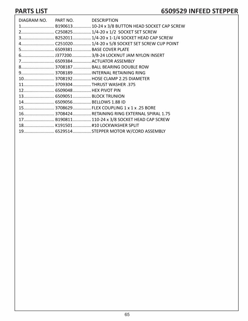
65
6509529 INFEED STEPPERPARTS LISTDIAGRAM NO. PART NO. DESCRIPTION1........................... B190613 ............... 10-24 x 3/8 BUTTON HEAD SOCKET CAP SCREW2........................... C250825 ...............1/4-20 x 1/2 SOCKET SET SCREW3........................... B252011 ............... 1/4-20 x 1-1/4 SOCKET HEAD CAP SCREW4........................... C251020 ...............1/4-20 x 5/8 SOCKET SET SCREW CUP POINT5........................... 6509381 ...............BASE COVER PLATE6........................... J377200................ 3/8-24 LOCKNUT JAM NYLON INSERT7........................... 6509384 ...............ACTUATOR ASSEMBLY8........................... 3708187 ...............BALL BEARING DOUBLE ROW9........................... 3708189 ............... INTERNAL RETAINING RING10......................... 3708192 ...............HOSE CLAMP 2.25 DIAMETER11......................... 3709304 ...............THRUST WASHER .37512......................... 6509048 ...............HEX PIVOT PIN13......................... 6509051 ...............BLOCK TRUNION14......................... 6509056 ...............BELLOWS 1.88 ID15......................... 3708629 ...............FLEX COUPLING 1 x 1 x .25 BORE16......................... 3708424 ...............RETAINING RING EXTERNAL SPIRAL 1.7517......................... B190811 ............... 110-24 x 3/8 SOCKET HEAD CAP SCREW18......................... K191501 ...............#10 LOCKWASHER SPLIT19......................... 6529514 ...............STEPPER MOTOR W/CORD ASSEMBLY

66
PARTS LIST 6339558 COMMON CARTON
1
2
6
5
4
3
7
8

67
6339558 COMMON CARTONPARTS LISTDIAGRAM NO. PART NO. DESCRIPTION1........................... 3706130 ...............DRIVE ADAPTERS2........................... 3708205 ...............SOCKET HOLDER3........................... 3700088 ...............GRINDING WHEEL 3.5 OD x .38 W x .502 B 24G4........................... 3700086 ...............GRINDING WHEEL 3.5 OD x 1 W x .502 B 24G5........................... 3700087 ...............GRINDING WHEEL 5 OD x.38 W x .502 B 24G6........................... 3700089 ...............GRINDING WHEEL 5 OD x 1 W x .502 B 24G7........................... 3707603 ...............BLUE LENS8........................... 3707465 ...............FLASHER BULB

68
6539519 ACCUTOUCH 3PARTS LIST
44
42
35
12
25
58
45 43
6
6
6
6
6
6
22
30
31
32
36
3738
46
41
1
3929
18
16
21
14
20520
2219
463
1
30
40
26
15
8
42
10
12
25
9
9
12
7
11
13
28
27
33/34
28

69
6539519 ACCU-TOUCH 3PARTS LIST DIAGRAM NO. PART NO. DESCRIPTION1................................. B190634 .....................10-32 x 3/8 FLAT HEAD SOCKET SCREW2................................. D250800 ....................1/4-20 THREAD CUTTING SCREW 3................................. R000465 .....................LOCK WASHER #10 EXTERNAL4................................. R000536 .....................LOCK WASHER 1/4 INTERNAL5................................. 80419 .........................POTENTIOMETER 10K6................................. 3706105 .....................DECAL SHEET (REEL GRINDER)7................................. 3706223 .....................HOLE PLUG .313 DIA8................................. 3706224 .....................HOLE PLUG 1.13 DIA9................................. 3707009 .....................LIQUID TIGHT STRAIN RELIEF .27-.47 DIA10............................... 3707029 .....................LIQUID TIGHT STRAIN RELIEF .19-.30 DIA11............................... 3707090 .....................SLOW-BLOW FUSE - 4 AMP 12............................... 3707093 .....................STRAIN RELIEF 13............................... 3707219 ..................... SLOW-BLOW FUSE - 2 AMP14............................... 3707342 .....................YELLOW E-STOP RING15............................... 3707367 .....................ROCKER SWITCH ON/OFF16............................... 3707446 .....................POTENTIOMETER KNOB W/POINTER17............................... 3708462 .....................DECAL WARNING 4500 RPM MIN18............................... 3707564 .....................GREEN PUSH BUTTON 19............................... 3707565 .....................CONTACT BLOCK NO20............................... 3707566 .....................LATCH MOUNTING 21............................... 3707567 .....................PUSH / PULL RED BUTTON22............................... 3707568 .....................CONTACT BLOCK NC 23............................... 3707595 .....................HOLE PLUG .875 DIA24............................... 3707597 .....................HOLE PLUG .625 DIA25............................... 3707658 .....................LIQUID TIGHT STRAIN RELIEF .54-.71 DIA26............................... 3707927 .....................FUSE HOLDER - PANEL MOUNT27............................... 3708419 .....................WAVE SPRING .78 ID28............................... 3708421 .....................FLAT WASHER .75 x 1.0 OD29............................... 6539047 .....................7" TOUCH SCREEN 30............................... 3708448 .....................ELECTRICAL WARNING DECAL 31............................... 3708872 .....................PATENT DECAL32............................... 3709990 .....................FOLEY UNITED DECAL33............................... 3707601 .....................PROXIMITY SWITCH 34............................... 6539078 .....................LEFT PROXIMITY SWITCH CORD ASSEMBLY................................... 6539079 .....................RIGHT PROXIMITY SWITCH CORD ASSEMBLY35............................... 6529019 .....................LIGHT BASE ASSEMBLY36............................... 3707603 .....................BLUE LIGHT LENS37............................... 3707465 .....................LIGHT BULB 120VAC - FLASHER38............................... 6339025 .....................DECAL SHEET 633/6539............................... 6539001 .....................ACCUTOUCH 3 CONTROL DECAL40............................... 6539046 .....................POWER SIWTCH DECAL41............................... 6539073 .....................CONTROL PANEL TOP42............................... 3706136 .....................VELCRO LOOP - 1"W43............................... 3706135 .....................VELCRO HOOK - 1"W44............................... 3706133 .....................CLEAR TUBE 3.5 OD45............................... 3706134 .....................END CAP - 3.5 ID B46............................... J197200 ......................10-32 HEX LOCKNUT JAM
ITEMS NOT SHOWN................................... 6539065 .....................CONTROL CABLE ASSEMBLY................................... 6539066 .....................LIGHT RECEPTACLE CORD................................... 6539067 .....................VACUUM RECEPTACLE CORD................................... 6539068 .....................FLASHER LIGHT CORD................................... 6539075 .....................SPIN DRIVE CORD ................................... 6539084 .....................RS232 CONNECTOR - .......................................................................ACCUTOUCH SCREEN................................... 6539085 .....................5PIN MINI DIN CONNECTOR.......................................................................PLC................................... 3707224 .....................CABLE TIE MOUNT ................................... 3707225 .....................CABLE TIE 6.5Lx.18................................... 3707255 .....................CABLE TIE 4Lx.10................................... 3708378 .....................STRIP FOAM .25T ................................... 6309111 .....................DECAL UP/DOWN

70
PARTS LIST 6539520 ACCUTOUCH 3 SUB CONTROL
18 17
16
6
39
3332
33
27
30
2616
6
2311
18
44
13
40
27
29
1821
20
22
1543
98
24 35
421
241
29
18
35 3430 31
3035
12
25
36
3
4
10
37
28

71
6539520 ACCUTOUCH 3 SUB CONTROLPARTS LISTDIAGRAM NO. PART NO. DESCRIPTION1........................... D130608 ..............6-32 x .38 PAN HEAD MACHINE SCREW2........................... D131266 ..............6 x 3/4 PHIL PAN SELF TAP3........................... D131666 ..............6 x 1 PHIL PAN SELF TAP4........................... D160866 ..............8 x 1/2 LG PHIL PA5........................... K160001 ...............FLAT WASHER #8 SAE6........................... 80259 ................... CIRCUIT BREAKER 207........................... 3706118 ...............PUSH IN CABLE TIE8........................... 3706148 ...............TERMINAL BLOCK RELAY9........................... 3706149 ...............2-POLE JUMPER FOR10......................... 3706150 ...............20 POLE JUMPER FOR11......................... 3707073 ...............SOCKET 8 PIN12......................... 3707163 ...............DECAL PRIMARY GROUP13......................... 3707164 ...............LUG GROUND PRIMARY14......................... 3707695 ...............2 POLE JUMPER15......................... 3707907 ...............DOOR SWITCH MONITOR16......................... 3707556 ............... STARTER MAGNETIC 117......................... 3707557 ...............RELAY - OVERLOAD 118......................... 3707625 ............... END STOP SCREWLESS19......................... 3707684 ...............TERMINAL BLOCK - 320......................... 3707685 ...............TERMINAL BLOCK - 321......................... 3707686 ............... END PLATE - TERM B22......................... 3707626 ............... JUMPER ADJACENT23......................... 3707688 ...............LOW VOLTAGE RELAY24......................... 3707694 ...............RELAY TERMINAL BLOCK25......................... 3707697 ...............DRIVE TRAVERSE26......................... 3707798 ...............RELAY TERM BLOCK 827......................... 3707829 ...............DIN RAIL 12”28......................... 3707839 ...............24VDC POWER SUPPLY29......................... 3707910 ...............TERMINAL BLOCK 3-POLE30......................... 3707913 ...............TERMINAL BLOCK 4-POLE31......................... 3707914 ...............TERMINAL BLOCK 4-POLE32......................... 3707915 ...............TERMINAL BLOCK 3-POLE33......................... 3707916 ...............TERMINAL BLOCK 3-POLE34......................... 3707917 ...............TERMINAL BLOCK 4-POLE35......................... 3707918 ...............TERMINAL BLOCK END36......................... 3707919 ...............2-POLE TERMINAL BLOCK37......................... 3707923 ............... STEPPER DRIVE 2AMP38......................... 3707925 ...............DIN RAIL 9.0 LG39......................... 3707936 ...............CIRCUIT BREAKER 1040......................... 3707937 ...............RFI LINE FILTER41......................... 3707940 ...............CONTROL BOARD FOR42......................... 3707942 ............... SPIN CONTROL BOARD43......................... 3707569 ...............PLC AROMAT44......................... 6539074 ...............CONTROL SUB PANEL45......................... 6539059 ...............PLC CABLE - INPUTS................................ 6539060 ...............PLC CABLE - OUTPUTS................................ 6539058 ...............PANEL WIRE HARNESS

72
WIRING DIAGRAM 6534519 - AC
110T
CHGD
(CO
NNEC
TS TO
PAN
ELW
ITH SC
REW
)
REAR D
OOR
SWITC
H W206
GAUG
E W
xx
MAIN
PWR W
32
RH PR
OXW3
7
FRONT
DOOR
SWITC
H W207
HEAD
PROX
W141
LH PR
OXW3
6FIN
GER P
ROX
W142
new Y6-SPIN PWR (NC)
new Y6-SPIN PWR
1 2 3G
- +
NCNCS3S2S1T2DIRMOD
TO p
lc
19SSM23
46RY8-1149RY71115RY6NC1240RY6NC11
50RY51439RY5-1164RY611
64SDCL1
48PWRGN
48GTB--
47GRND--
47TDCGND
46TDCL1
55TBW-N
55TBF-N
53RYE1454RYE11
53TBL-N
54TBV-N
52TBV-L
51RYE24
51TBL-L
49TBF-L
43SRL21
43MAGL3
63TBG-L
63RELT1
42TBG-N
42RELT240REL21
39RELA1
38RELL1
38GCB--
62TBW-L
62VCB--
61RELL2
61BT4-3
60RELA2
60BT4-2
59MAGT2
59BT4-1
58TDCL2
58BT3-3
57TBF-N
57BT3-2
56SDCL2
56BT3-1
30GT7-3
30VCB--
29GCB--
29GT7-2
27GT6-2
27MAGT1
25BT2-3
25PWRL2
24BT2-1
24MAGA2
23MAGL2
23BT1-3 21BT1-1
21LVR-6
22SRLA2
22BT1-2
18REL22
18GT5-219GT5-3
16SSM24
16GT4-415GT4-3
14GT4-2
14MAGT3
13SRL24
11GT3-3
11RYF11
08GT2-309GT2-4
08PWR-L
09RYF14
07GT2-2
07LVR-7
03MCB--
04MAGL1
03GT1-404GT1-3
02BT2-2
02FTRBU
01MCB--
01FTRBR
107TBW-L
108TBW-N
108TBL-N
107TBL-L
45GT5-4
45MAGA1
17SS
S-4
(WHI
TE)
13SS
S-3
67FS3--
94BT5-3
xxGRND--
xxTCHGD
93TCHV+
93GT9-4
94TCHV-
66PS
W-2
66FS1--
67RY714
50FS2--
44SRLA1
17ES
S-1
(BLA
CK)
17ES
2-2
(RED
)
06PSW-3
05FS1--
28FS2--
26FS3--
28GT7-126GT6-1
44GT5-113GT4-1
13GT3-106GT2-1
05GT1-1
TT6
TT5
TT4TT3
TT2
TT1TT0
32FTRBR
32GR
D-
32FTRBL
a1=v
+
14y4
4a2
y34
a1y1
y21323
s13
s12
s11
AFTER RELAY YF
YE-VAC
Y9-SPIN
YF-STOP
Y8-TRAV POWER
Y7-FLASHING LIGHT
Y5-GRIND RELAY
YC-TRAV LEFT (WAS Y3)
YB-TRAV RIGHT (WAS Y2)
DOOR/GND & SPN TO A1 ON MAG/REL
PWR BACK FROM START
PWR BACK FROM PWR SWITCH
POWER IN FROM FILTER
SSS
TSP
START 4
3 ESS STOP
TOUC
H SC
REEN
4A - Spin
4A-Trav
65
3214
12
12
2A- Fuse
V-V-
V+ A2A1141112
22 21 24
24212212 11 14
A2A1
24212212 11 14
A2A1
(WIRE 25)
TCH
RH P
ROX
HEAD
PRO
X
FING
ER P
ROX
LH P
ROX
52RYE21
GRI
ND
MO
TOR
W31
SPIN
MO
TOR
W33
TRA
VER
SEM
OTO
R W
34
FLA
SHER
W
143
WIN
CH
W13
9
VA
C P
LUG
W13
0LI
GHT
W
129
INFE
ED
MO
TOR
W13
7
GT1
GT2
GT3
GT4
GT5
BT1
BT2
GT6
GT7
BT3
BT4
VC
BV
AC
/W
INC
H/LI
GHT
GC
BG
RIN
DM
OTO
R
REL
GRI
ND
MO
TOR
MA
GM
AIN
CO
NTA
CTO
RSR
LST
ART
RELA
YM
CB
MA
INC
IRC
UIT
BREA
KER
LVR
LOW
VO
LTRE
LAY
FTR
LIN
E FI
LTER
SDC
SPIN
DRI
VE
CO
NTR
OL
TDC
TRA
VER
SED
RIV
E C
ON
TRO
L
PWR
DC
PO
WER
SUP
PLY
SIC
ST
EPPE
R IN
FEED
CO
NTR
OL
PSW
POW
ERSW
ITCH
PLC
SSM
DO
OR
SAFE
TYSW
ITCH
MO
NITO
R
TT_
TIER
TERM
INA
LBL
OC
KG
T8G
T9BT
5BT
6BT
7BT
8G
T10G
T11
129TBL-G
129TBL-N
129TBL-L
(GREEN)
(WHITE)
(BLACK)
(WHITE)
(BLACK)
(GREEN)
(WHITE)
(BLACK)
(GREEN)
(WHITE)
(BLACK)
(GREEN)
(BLACK)
(WHITE)
(GREEN)
(BLACK)
(WHITE)
(GREEN)
(BLACK)
130TBV-G
206TBW-G
143TBF-G
34TBT-G
33TBS-G
31TBG-G
130TBV-N
206TBW-N
143TBF-N
33TBS-N
34TBT-N
130TBV-L
206TBW-L
143TBF-L
33TBS-L
34TBT-L
31TBG-N31TBG-N31TBG-L31TBG-L
(ORANGE)
(WHITE)
(RED)
(GREEN)
137S
ICB-
(GRE
EN)
137S
ICB+
(RED
)
137S
ICA
- (W
HITE
)13
7SIC
A+
(BLA
CK)
ON
8 -(
ON
)7 6
-(O
N)
5 4 3 -(
ON
)2
-(O
N)
1
OFF
SWITC
HES
ON
TOP:
1,
2,4=
ON
3= O
FF
FWD ACCFULL CCWREV ACCFULL CCWMAX SPEEDIR COMP3:00REV TQ10:30FWD TQ10:30DB3:00MIN SPDFULL CCWTACH3:00
ARMATURE90-180
FEEDBACKARM-TACH
SPEED
IDLE TQ
TORQ
IR COMP
12:00
10:00
2:00
12:00
13ES
S-1
35TDC-BL35TDC-S0 (WHITE)
35TDC-S2 (RED)
206SSMS13 (GREEN)
206SSMS12 (YELLOW)206SSMS11 (WHITE)206SSMS11 (BROWN)
206P
LC--
(PIN
K)
206D
C-V
- (BL
UE)
37TT6BK141TT5BK142TT4BK36TT3BK
205TT1BK
207SSMS21 (WHITE)
207SSMS23 (GREEN)
207SSMS22 (YELLOW)
207SSMS21 (BROWN)
207D
C-V
- (BL
UE)
207P
LC--
(PIN
K)
205TT2BU205TT1BU
205TT1BR
109G
ND--
24+SPDTRQDIRMODCOMSIGFRQ

73
WIRING DIAGRAM 6534519 - AC
GROUND SCREW
WIRE CONNECTION
TERM. TO TERM CONNECTION
BTX - BLUE TERMINAL BLOCK ESS- EMERGENCY STOP SWITCHFS1-2 AMP FUSE (DC PWR)FS2-4 AMP FUSE (SPIN/ GRIND RELAY)FS3-4 AMP FUSE (TRAVERSE)FTR- FILTERGCB - GRIND MOTOR CIRCUIT BREAKERGSI- GAUGE / SPIN INTERFACEGTX - GREY TERMINAL BLOCKLVR- LOW VOLTAGE RELAYMAG- MAGNETIC STARTERMCB- MAIN CIRCUIT BOARD 20 AMPREL- GRIND MOTOR RELAYPLC- PROGRAMMABLE LOGIC CONTROLLERPSW- POWER SWITCH CONTROL BOXPWR- DC POWER SUPPLY
SDC- SPIN DRIVE CONTROLSIC- STEPPER INFEED CONTROLSRL - START RELAYSSM- SAFETY SWITCH MONITORSSS-SYSTEM START SWITCTBX - TERMINAL BLOCK (X: L=LIGHT, V=VACUUM, W=WINCH F=FLASHER, T=TRAVERSE, S=SPIN MOTOR, G= GRINDTCH- TOUCH SCREENTDC- TRAVERSE DRIVE CONTROLTSP- TRAVERSE SPEED POTTTX - TIER TERMINAL BLOCKVCB- VACUUM/WINCH CIRCUIT BREAKERYXX - OUTPUT RELAYS
110T
CHGD
(CO
NNEC
TS TO
PAN
ELW
ITH SC
REW
)
REAR D
OOR
SWITC
H W206
GAUG
E Wx
x
MAIN
PWR W
32
RH PR
OXW3
7
FRONT
DOOR
SWITC
H W207
HEAD P
ROX
W141
LH PRO
XW3
6FIN
GER P
ROX
W142
new Y6-SPIN PWR (NC)
new Y6-SPIN PWR
1 2 3G
- +
NCNCS3S2S1T2DIRMOD
TO p
lc
19SSM23
46RY8-1149RY71115RY6NC1240RY6NC11
50RY51439RY5-1164RY611
64SDCL1
48PWRGN
48GTB--
47GRND--
47TDCGND
46TDCL1
55TBW-N
55TBF-N
53RYE1454RYE11
53TBL-N
54TBV-N
52TBV-L
51RYE24
51TBL-L
49TBF-L
43SRL21
43MAGL3
63TBG-L
63RELT1
42TBG-N
42RELT240REL21
39RELA1
38RELL1
38GCB--
62TBW-L
62VCB--
61RELL2
61BT4-3
60RELA2
60BT4-2
59MAGT2
59BT4-1
58TDCL2
58BT3-3
57TBF-N
57BT3-2
56SDCL2
56BT3-1
30GT7-3
30VCB--
29GCB--
29GT7-2
27GT6-2
27MAGT1
25BT2-3
25PWRL2
24BT2-1
24MAGA2
23MAGL2
23BT1-3 21BT1-1
21LVR-6
22SRLA2
22BT1-2
18REL22
18GT5-219GT5-3
16SSM24
16GT4-415GT4-3
14GT4-2
14MAGT3
13SRL24
11GT3-3
11RYF11
08GT2-309GT2-4
08PWR-L
09RYF14
07GT2-2
07LVR-7
03MCB--
04MAGL1
03GT1-404GT1-3
02BT2-2
02FTRBU
01MCB--
01FTRBR
107TBW-L
108TBW-N
108TBL-N
107TBL-L
45GT5-4
45MAGA1
17SS
S-4
(WHI
TE)
13SS
S-3
67FS3--
94BT5-3
xxGRND--
xxTCHGD
93TCHV+
93GT9-4
94TCHV-
66PS
W-2
66FS1--
67RY714
50FS2--
44SRLA1
17ES
S-1
(BLA
CK)
17ES
2-2
(RED
)
06PSW-3
05FS1--
28FS2--
26FS3--
28GT7-126GT6-1
44GT5-113GT4-1
13GT3-106GT2-1
05GT1-1
TT6
TT5
TT4TT3
TT2
TT1TT0
32FTRBR
32GR
D-
32FTRBL
a1=v
+
14y4
4a2
y34
a1y1
y21323
s13s12
s11
AFTER RELAY YF
YE-VAC
Y9-SPIN
YF-STOP
Y8-TRAV POWER
Y7-FLASHING LIGHT
Y5-GRIND RELAY
YC-TRAV LEFT (WAS Y3)
YB-TRAV RIGHT (WAS Y2)
DOOR/GND & SPN TO A1 ON MAG/REL
PWR BACK FROM START
PWR BACK FROM PWR SWITCH
POWER IN FROM FILTER
SSS
TSPSTA
RT 43 ESS STO
P
TOUC
H SC
REEN
4A - Spin
4A-Trav
65
3214
12
12
2A- Fuse
V-V-
V+ A2A1141112
22 21 24
24212212 11 14
A2A1
24212212 11 14
A2A1
(WIRE 25)
TCH
RH P
ROX
HEAD
PRO
X
FING
ER P
ROX
LH P
ROX
52RYE21
GRI
ND
MO
TOR
W31
SPIN
MO
TOR
W33
TRA
VERS
EM
OTO
R W
34
FLA
SHER
W
143
WIN
CH
W13
9
VAC
PLU
GW
130
LIGHT
W
129
INFE
ED
MO
TOR
W13
7
GT1
GT2
GT3
GT4
GT5
BT1
BT2
GT6
GT7
BT3
BT4
VCB
VAC
/W
INC
H/LIG
HT
GC
BG
RIN
DM
OTO
R
REL
GRI
ND
MO
TOR
MA
GM
AIN
CO
NTA
CTO
RSR
LST
ART
RELA
YM
CB
MA
INC
IRC
UIT
BREA
KER
LVR
LOW
VO
LTRE
LAY
FTR
LINE
FILTE
R
SDC
SPIN
DRI
VEC
ON
TRO
L
TDC
TRA
VERS
ED
RIVE
CO
NTR
OL
PWR
DC
PO
WER
SUP
PLY
SIC
STEP
PER
INFE
ED C
ON
TRO
L
PSW
POW
ERSW
ITCH
PLC
SSM
DO
OR
SAFE
TYSW
ITCH
MO
NITO
R
TT_
TIER
TERM
INA
LBL
OC
KG
T8G
T9BT
5BT
6BT
7BT
8G
T10G
T11
129TBL-G
129TBL-N
129TBL-L
(GREEN)
(WHITE)
(BLACK)
(WHITE)
(BLACK)
(GREEN)
(WHITE)
(BLACK)
(GREEN)
(WHITE)
(BLACK)
(GREEN)
(BLACK)
(WHITE)
(GREEN)
(BLACK)
(WHITE)
(GREEN)
(BLACK)
130TBV-G
206TBW-G
143TBF-G
34TBT-G
33TBS-G
31TBG-G
130TBV-N
206TBW-N
143TBF-N
33TBS-N
34TBT-N
130TBV-L
206TBW-L
143TBF-L
33TBS-L
34TBT-L
31TBG-N31TBG-N31TBG-L31TBG-L
(ORANGE)
(WHITE)
(RED)
(GREEN)
137S
ICB-
(GRE
EN)
137S
ICB+
(RED
)
137S
ICA
- (W
HITE
)13
7SIC
A+
(BLA
CK)
ON
8 -(O
N)
7 6 -(O
N)
5 4 3 -(O
N)
2 -(O
N)
1
OFF
SWITC
HES
ON
TOP:
1,
2,4=
ON
3= O
FF
FWD ACCFULL CCWREV ACCFULL CCWMAX SPEEDIR COMP3:00REV TQ10:30FWD TQ10:30DB3:00MIN SPDFULL CCWTACH3:00
ARMATURE90-180
FEEDBACKARM-TACH
SPEED
IDLE TQ
TORQ
IR COMP
12:00
10:00
2:00
12:00
13ES
S-1
35TDC-BL35TDC-S0 (WHITE)
35TDC-S2 (RED)
206SSMS13 (GREEN)
206SSMS12 (YELLOW)206SSMS11 (WHITE)206SSMS11 (BROWN)
206P
LC--
(PIN
K)
206D
C-V
- (BL
UE)
37TT6BK141TT5BK142TT4BK36TT3BK
205TT1BK
207SSMS21 (WHITE)
207SSMS23 (GREEN)
207SSMS22 (YELLOW)
207SSMS21 (BROWN)
207D
C-V
- (BL
UE)
207P
LC--
(PIN
K)
205TT2BU205TT1BU
205TT1BR10
9GND
--
24+SPDTRQDIRMODCOMSIGFRQ

74
RH PR
OXW3
7
110T
CHGD
(CO
NNEC
TS TO
PAN
ELW
ITH SC
REW
)
GAUG
E W
xx
REAR D
OOR
SWITC
H W206
new Y6-SPIN PWR
new Y6-SPIN PWR (NC)
FINGE
R PRO
XW1
42LH
PROX
W36
HEAD
PROX
W141
1 2 3G
- +
FRONT
DOOR
SWITC
H W207
NCNCS3S2S1T2DIRMOD
MAIN
PWR W
32
RH P
ROX
HEAD
PRO
X
FING
ER P
ROX
LH P
ROX
V-V-
V+ A2A1141112
22 21 24
24212212 11 14
A2A1
24212212 11 14
A2A1
TCH
43
TOUC
H SC
REEN
4A - Spin
4A-Trav
65
3214
12
12
2A- Fuse
a1=v
+
v+
14y4
4a2
y34
a1y1
y21323
s13
s12
s11
s21
s22
s23
24
AFTER RELAY YF
YE-VAC
Y9-SPIN
YF-STOP
Y8-TRAV POWER
Y7-FLASHING LIGHT
Y5-GRIND RELAY
YC-TRAV LEFT (WAS Y3)
YB-TRAV RIGHT (WAS Y2)
DOOR/GND & SPN TO A1 ON MAG/REL
PWR BACK FROM START
PWR BACK FROM PWR SWITCH
POWER IN FROM FILTER
71RY921
70RY911
70TBS-L
71TBS-N
73TBT-N
72TDCA1
73TDCA274REL14
76GT11-2
80BT7-3
76MAG14
75MAG22
77LVR-8
78MAG13
79BT7-2
78GT8-2
81GT11-1
75BT6-1
80TT0BU
83GT10-4
83SSMA1
84RYB14
84TPTBL
86TD
CS1
85TD
CS3
87RYEA1
88RYFA1
88GT9-1
87GT10-2
89RY924
90RY914
90SDCA1
89SDCA2
91GT8-4
91PWRV+
92PWRV-
92BT5-4
96SICV+95SICV-
96GT10-397GT11-4
95BT6-3
81TT0BR82SSMA2
74BT7-1 77BT6-282BT5-1
79SRL12
72TBT-L
97SICC+
86RYC1185RYB11
100TT1-BK
98GSIV+
100GSISIG99GSICOM
98GT11-3
99BT7-4
TT6
TT5
TT4
TT3
TT2
TT1
TT0
PSW
POW
ERSW
ITCH
SDC
SPIN
DRI
VE
CO
NTR
OL
12:00
IDLE TQ
2:00
12:00
PWR
DC
PO
WER
SUP
PLY
SWITC
HES
ON
TOP:
1,
2,4=
ON
3= O
FF
IR COMP3:00
MAX SPEED
REV ACCFULL CCW
FEEDBACKARM-TACH
ARMATURE90-180
FWD ACCFULL CCW
DB3:00MIN SPDFULL CCWTACH3:00
TDC
TRA
VER
SED
RIV
E C
ON
TRO
L
GT1
1G
T10
BT8
BT7
BT6
BT5
GT9
GT8
PLC
SSM
DO
OR
SAFE
TYSW
ITCH
MO
NITO
R
TT_
TIER
TERM
INA
LBL
OC
K
BT4
BT3
GT7
GT6
BT2
BT1
GT5
GT4
GT3
GT2
GT1
LVR
LOW
VO
LTRE
LAY
MC
BM
AIN
CIR
CUI
TBR
EAKE
R
MA
GM
AIN
CO
NTA
CTO
RSR
LST
ART
RELA
Y
VC
BV
AC
/W
INC
H/LI
GHT
GC
BG
RIN
DM
OTO
R
REL
GRI
ND
MO
TOR
STOP
ESS
TSP
SSSSTART
32GRD-
32FTRBR
32FTRBL
INFE
ED
MO
TOR
W13
7
LIG
HT
W12
9V
AC
PLU
GW
130
WIN
CH
W13
9FL
ASH
ER
W14
3
TRA
VER
SEM
OTO
R W
34SP
IN M
OTO
RW
33
GRI
ND
MO
TOR
W31
206TBW-G
206TBW-N
34TBT-L
33TBS-L
143TBF-L
206TBW-L
130TBV-L
34TBT-N
33TBS-N
143TBF-N
130TBV-N
33TBS-G
34TBT-G
143TBF-G
130TBV-G
(GREEN)
(WHITE)
(BLACK)
(GREEN)
(WHITE)
(BLACK)
(GREEN)
(BLACK)
(WHITE)
(GREEN)
(BLACK)
(WHITE)
(GREEN)
(BLACK)
(WHITE)
(BLACK)
(WHITE)
(GREEN)
129TBL-L
129TBL-N
129TBL-G
(GREEN)
(RED)
(WHITE)
(ORANGE)
31TBG-L31TBG-L31TBG-N31TBG-N
31TBG-G
(BLACK)
151BT8-1
151RY5-A2
24+SPDTRQDIRMODCOMSIGFRQ
150GSIFRQ
150TT3-BK
150TT5-BK150TT4-BK
150TT6-BK
150LVR-1
150MAG21
150SLR-11
150GT9-3
REA
R D
OO
R FRONT DOOR
150REL13
207P
LC--
(PIN
K)
207D
C-V
- (B
LUE)
207SSMS21 (BROWN)
207SSMS22 (YELLOW)
207SSMS23 (GREEN)
207SSMS21 (WHITE)
PLC-BLU
PLC-BRN
PLC-GRN
111D
C-V-
111BT8-X
151GSISPD151GSITRQ151GSIDIR151GSIMOD
137S
ICA
+ (B
LAC
K)13
7SIC
A- (
WHI
TE)
137S
ICB+
(RED
)
137S
ICB-
(GRE
EN)
206P
LC--
(PIN
K)
206D
C-V-
(B
LUE)
206SSMS13 (GREEN)
206SSMS12 (YELLOW)
206SSMS11 (WHITE)
206SSMS11 (BROWN)
205TT1BR205TT1BK205TT1BU205TT2BU36TT3BK
142TT4BK141TT5BK37TT6BK
111D
C-V-WHIT
E/BL
ACK (
PLC)
WHIT
E (PL
C)
ON
8 -(
ON
)7 6
-(O
N)
5 4 3 -(
ON
)2
-(O
N)
1
OFF
151RY6-A2
JUMPER
151RY5-A1151RYC-A2
151RYB-A2151RY5-A2
151RY7-A2
151RY8-A2
151RYF-A2
151RY9-A2
151RYE-A2
111BT8-X151BT8-4
151RY8-A1
106G
SI-M
O10
5GSI-
DIR
104G
SI-T2
103GSI-S1102GSI-S2101GSI-S3
101SDCS3102SDCS2
103SDCS1 104S
DCT2
105S
DCDI
R
106S
DCM
OD
93GT9-494BT5-3
xxGRND--
TO p
lc
94TCHV-
93TCHV+
xxTCHGD
65SSM13
65BT6-4
150SSM14
WIRING DIAGRAM 6534519 - DC

75
RH PR
OXW3
7
110T
CHG
D(C
ON
NEC
TS T
O P
AN
ELW
ITH S
CRE
W)
GAUG
E W
xx
REAR
DOOR
SWITC
H W20
6
new Y6-SPIN PWR
new Y6-SPIN PWR (NC)
FINGE
R PRO
XW1
42LH
PROX
W36
HEAD
PROX
W141
1 2 3G
- +FRO
NT DO
ORSW
ITCH W
207
NCNCS3S2S1T2DIRMOD
MAIN
PWR W
32
RH P
ROX
HEA
D P
ROX
FING
ER P
ROX
LH P
ROX
V-V-
V+ A2A1141112
22 21 24
24212212 11 14
A2A1
24212212 11 14
A2A1
TCH
43
TOUC
H SC
REEN
4A - Spin
4A-Trav
65
3214
12
12
2A- Fuse
a1=v
+
v+
14y4
4a2
y34
a1y1
y21323
s13
s12
s11
s21
s22
s23
24
AFTER RELAY YF
YE-VAC
Y9-SPIN
YF-STOP
Y8-TRAV POWER
Y7-FLASHING LIGHT
Y5-GRIND RELAY
YC-TRAV LEFT (WAS Y3)
YB-TRAV RIGHT (WAS Y2)
DOOR/GND & SPN TO A1 ON MAG/REL
PWR BACK FROM START
PWR BACK FROM PWR SWITCH
POWER IN FROM FILTER
71RY921
70RY911
70TBS-L
71TBS-N
73TBT-N
72TDCA1
73TDCA274REL14
76GT11-2
80BT7-3
76MAG14
75MAG22
77LVR-8
78MAG13
79BT7-2
78GT8-2
81GT11-1
75BT6-1
80TT0BU
83GT10-4
83SSMA1
84RYB14
84TPTBL
86TD
CS1
85TD
CS3
87RYEA1
88RYFA1
88GT9-1
87GT10-2
89RY924
90RY914
90SDCA1
89SDCA2
91GT8-4
91PWRV+
92PWRV-
92BT5-4
96SICV+95SICV-
96GT10-397GT11-4
95BT6-3
81TT0BR82SSMA2
74BT7-1 77BT6-282BT5-1
79SRL12
72TBT-L
97SICC+
86RYC1185RYB11
100TT1-BK
98GSIV+
100GSISIG99GSICOM
98GT11-3
99BT7-4
TT6
TT5
TT4
TT3
TT2
TT1
TT0
PSW
POW
ERSW
ITC
H
SDC
SPIN
DR
IVE
CO
NTR
OL
12:00
IDLE TQ
2:00
12:00
PWR
DC
PO
WER
SU
PPLY
SWIT
CH
ES O
NTO
P:
1,2,
4= O
N3=
OFF
IR COMP3:00
MAX SPEED
REV ACCFULL CCW
FEEDBACKARM-TACH
ARMATURE90-180
FWD ACCFULL CCW
DB3:00MIN SPDFULL CCWTACH3:00
TDC
TRA
VER
SED
RIV
E C
ON
TRO
L
GT1
1G
T10
BT8
BT7
BT6
BT5
GT9
GT8
PLC
SSM
DO
OR
SAFE
TYSW
ITC
H
MO
NIT
OR
TT_
TIER
TER
MIN
AL
BLO
CK
BT4
BT3
GT7
GT6
BT2
BT1
GT5
GT4
GT3
GT2
GT1
LVR
LOW
VO
LTR
ELA
YM
CB
MA
INC
IRC
UIT
BREA
KER
MA
GM
AIN
CO
NTA
CTO
RSR
LST
AR
TR
ELA
Y
VC
BV
AC
/W
INC
H/
LIG
HT
GC
BG
RIN
DM
OTO
R
REL
GR
IND
MO
TOR
STOP
ESS
TSP
SSSSTART
32GRD-
32FTRBR
32FTRBL
INFE
ED
MO
TOR
W
137
LIG
HT
W12
9V
AC
PLU
GW
130
WIN
CH
W13
9FL
ASH
ER
W14
3
TRA
VER
SEM
OTO
R W
34SP
IN M
OTO
RW
33
GR
IND
MO
TOR
W31
206TBW-G
206TBW-N
34TBT-L
33TBS-L
143TBF-L
206TBW-L
130TBV-L
34TBT-N
33TBS-N
143TBF-N
130TBV-N
33TBS-G
34TBT-G
143TBF-G
130TBV-G
(GREEN)
(WHITE)
(BLACK)
(GREEN)
(WHITE)
(BLACK)
(GREEN)
(BLACK)
(WHITE)
(GREEN)
(BLACK)
(WHITE)
(GREEN)
(BLACK)
(WHITE)
(BLACK)
(WHITE)
(GREEN)
129TBL-L
129TBL-N
129TBL-G
(GREEN)
(RED)
(WHITE)
(ORANGE)
31TBG-L31TBG-L31TBG-N31TBG-N
31TBG-G
(BLACK)
151BT8-1
151RY5-A2
24+SPDTRQDIRMODCOMSIGFRQ
150GSIFRQ
150TT3-BK
150TT5-BK150TT4-BK
150TT6-BK
150LVR-1
150MAG21
150SLR-11
150GT9-3
REA
R
DO
OR FRONT DOOR
150REL13
207P
LC--
(P
INK)
207D
C-V
- (B
LUE)
207SSMS21 (BROWN)
207SSMS22 (YELLOW)
207SSMS23 (GREEN)
207SSMS21 (WHITE)
PLC-BLU
PLC-BRN
PLC-GRN
111D
C-V
-
111BT8-X
151GSISPD151GSITRQ151GSIDIR151GSIMOD
137S
ICA
+ (B
LAC
K)13
7SIC
A-
(WH
ITE)
137S
ICB+
(RED
)
137S
ICB-
(GR
EEN
)
206P
LC--
(PIN
K)
206D
C-V-
(B
LUE)
206SSMS13 (GREEN)
206SSMS12 (YELLOW)
206SSMS11 (WHITE)
206SSMS11 (BROWN)
205TT1BR205TT1BK205TT1BU205TT2BU36TT3BK
142TT4BK141TT5BK37TT6BK
111D
C-V
-
WHI
TE/B
LAC
K (P
LC)
WHI
TE (P
LC)
ON
8 -(
ON
)7 6
-(O
N)
5 4 3 -(
ON
)2
-(O
N)
1
OFF
151RY6-A2
JUMPER
151RY5-A1151RYC-A2
151RYB-A2151RY5-A2
151RY7-A2
151RY8-A2
151RYF-A2
151RY9-A2
151RYE-A2
111BT8-X151BT8-4
151RY8-A1
106G
SI-M
O10
5GSI-
DIR
104G
SI-T2
103GSI-S1102GSI-S2101GSI-S3
101SDCS3102SDCS2
103SDCS1 104S
DCT2
105S
DCDI
R
106S
DCM
OD
93GT9-494BT5-3
xxGRND--
TO p
lc
94TCHV-
93TCHV+
xxTCHGD
65SSM13
65BT6-4
150SSM14
BTX - BLUE TERMINAL BLOCK ESS- EMERGENCY STOP SWITCHFS1-2 AMP FUSE (DC PWR)FS2-4 AMP FUSE (SPIN/ GRIND RELAY)FS3-4 AMP FUSE (TRAVERSE)FTR- FILTERGCB - GRIND MOTOR CIRCUIT BREAKERGSI- GAUGE / SPIN INTERFACEGTX - GREY TERMINAL BLOCKLVR- LOW VOLTAGE RELAYMAG- MAGNETIC STARTERMCB- MAIN CIRCUIT BOARD 20 AMPREL- GRIND MOTOR RELAYPLC- PROGRAMMABLE LOGIC CONTROLLERPSW- POWER SWITCH CONTROL BOXPWR- DC POWER SUPPLY
SDC- SPIN DRIVE CONTROLSIC- STEPPER INFEED CONTROLSRL - START RELAYSSM- SAFETY SWITCH MONITORSSS-SYSTEM START SWITCTBX - TERMINAL BLOCK (X: L=LIGHT, V=VACUUM, W=WINCH F=FLASHER, T=TRAVERSE, S=SPIN MOTOR, G= GRINDTCH- TOUCH SCREENTDC- TRAVERSE DRIVE CONTROLTSP- TRAVERSE SPEED POTTTX - TIER TERMINAL BLOCKVCB- VACUUM/WINCH CIRCUIT BREAKERYXX - OUTPUT RELAYS
WIRING DIAGRAM 6534519 - DC

76
WIRING SCHEMATIC
TSP37 (1)
L2
+
101
EMERGENCY STOP
SPIN DRIVE BOARD
20A
(1)
MCB11
3
1-25FROM LINE
GRN
(2)
1-25FROM LINE
(1)
BLUBRNGRN
GROUND LUG
GROUND LUG
BLU
BRN
LOAD
120 VAC 1 PHPOWER CORD
LINE
FTR8
SPEEDREMOTE
TORQUEREMOTE
2
FLASHER UNITYLIGHT AND
MBLK
GRN
WHT
14
L2
S0
L1
A2
A1
43
42
40
S2
41
S3
WHT
YB
RED
BLK
SHIELD
GRIND MOTOR
TRAVERSE DRIVE BOARD
GRN
WHT
M
N25
(1)
L2
14A1
L1
(1)
COMM
T3
T2
T1
MODE
A2
S3
S1
S2
24BLK
YC
S1 GND
20A
1
4A
WINCH
VACUUM
10K OHM
24VDC CONTROLPOWER SUPPLY
M
100
TO LINE3-100
L1
24VDC
32
2A
LOW VOLTAGE RELAY
TO LINE
(1)
7 6
1
8
3-113
-
11
2
1
33
34
41
40
36
35
26
28
29
27
30
31
32
37
38
3
4
5
6
7
9
8
10
11
12
13
42
43
44
45
47
48
46
49
50
15
16
17
18
19
20
22
23
21
24
25
14 39
L1
A1
GRINDMOTOR
M
SSM
DIRECTION
COMD
Y6 -NCSPIN
RELGRIND
SLR MAG
SSS reset
A1
1114 2 41
24 21 L3 T3
12 11
24 23
21 22
ESSYFPWRFUSE-DC SLR
MAG
GT2
PWR
LVR
GT1 GT3 GT4 GT5
GT6/7
FUSE-TRAV
11
Y7FLASHER
GT6/7
GT6/7
GT2
T1MAG MAG
L2
T2
11
Y8TRAVERSE
11
11
14
Y7-14
YB-14
4A
FUSE-SPIN
1114
Y5GRIND
Y6SPIN
Y5-14
RELGRIND
A1 A2
A2
A2
GCB REL
L1 T1 T1
RELOVERLOAD
RELOVERLOAD
REL
T2 L2T2 BT3/4
BT3/4
BT3/4
BT3/4
BT3/4
FLASHER
TDC
SDC
VCB
10A
VACUUM
WINCH
M
YEVACUUM
YEVACUUM
2124 1411
BT1/2
BT1/2
BT1/2
BT1/2
BT1/2
TO GSILINE 5-321
GRIND MOTOR CONTROLREALAY
[5-308]
[1-28]
[1-43] [1-43]
V-
[1-43]
11
21
Y9
Y9
[4-214]
[4-214]
[4-211]
[4-213]
[4-208]
[4-209]
[4-210]
[4-219]

77
WIRING SCHEMATIC
214114
125
124
121
123
122
120
119
118
117
116
115
225
224
221
223
222
220
219
218
216
215
112
111
110
108
109
107
106
105
102
104
103
101
213
212
211
210
208
209
207
206
205
202
204
203
201
217
24 VDC(+)
3 2TCH BT5/6/7/8
TOUCH SCREENOMRON
3 424VDC -
FROM LINE1-17,18 - DC POWER SUPPLY
GT8/9
BLURED PLC AROMAT FPOPLC
COMMUNICATION CABLE
BT5/6/7/8
MAG13
1
RS-232
GRNPULSE INPUT FROM GSI
BLUBLK
BRN
TT5
TT6
LEFT TRAVERSE PROX
RIGHT TRAVERSE PROX
FINGER DOWN/STORED PROX
HEAD IN RELIEF POS. PROX
LOW VOLTAGE RELAY
E-STOP OPEN
1BT5/6/7/8GT8/9
113
START RELAY
REAR DOOR
FRONT DOOR
GRIND MOTOR RELAY
TT4
TT3
[1-13]8
21
[1-21]
MAG
14REL
PKSSM
PKSSM
1
[1-14]
SLR
22
LVR
[1-43]
1
13
8
5-305 [A]GY
5-305 [B]
GY
X0
X1
X2
X3
X4
X5
X6
X7
X8
X9
XA
X-COM
BRN
BLK BLU
BRN
BLK BLU
BRN
BLK BLU
Y0
PLC INPUTS - COM
24VDC+
FROM LINE1-17,18 PLC
INPUTSX0-F
PLCOUTPUTS
Y0-F
24VDC-
Y1
Y2
Y3
Y4
A2A1Y5
A2A1Y6
A2A1
Y7A2A1
Y8
Y9
A2A1
YA
A2A1
YB
YC
A2A1
YD
A2A1
YE
YF
A2A1
A2A1
Y5
Y6
Y6-NC
Y7
Y8
Y9
YB
YC
YE
YF
TO LINE5-312
STEPPER INFEED PULSE OUT
STEPPER INFEED DIRECTION
RELIEF TORQUE
GRIND MOTOR RELAY
SPIN MOTOR ON
NC-RELAY - SPIN MOTOR[FOR START CIRCUIT]
FLASHING LIGHT
TRAVERS DIRVE POWER
SPIN MOTOR POWER
SPIN MOTOR DIRECTION
TRAVERSE MOTOR DIRECTION
TRAVERSE MOTOR DIRECTION
VACUUM ON
ESTOP
TO LINE5-321
SPIN SPEED
SPIN/TORQUE MODE SELECTOR
TO LINE5-323
Y-COM
Y-COM
13
14
BT5/6/7/8
FROM 5-301 24VDC+FROM 5-324
GSI - FRQ
GT8/9
GT8/9
GT10/11
TT3
TT6
TT5
TT4
1BT5/6/7/8
1BT5/6/7/8
1BT5/6/7/8
1BT5/6/7/8
1BT5/6/7/8
1BT5/6/7/8
5-305
[5-308]SSM1BT5/6/7/81314
XB DOOR SWITCH MONITOR

78
WIRING SCHEMATIC
= CLOSED POSITION OF SAFETY SWITCH
= DC SWITCH (PROXIMITY)
= JUMP TO NEW SPOT IN SCHEMATIC
= LOAD (RELAY COIL, MOTOR, ETC.)
= NORMALLY OPEN PUSH SWITCH
= NORMALLY CLOSED PUSH/PULL SWITCH
= ON/OFF ROCKER OR TOGGLE SWITCH
INTERNAL CONTACTSIN SAFETY SWITCH
4-225
FROM LINE65
326
328
329
327
330
331
332
334
333
335
336
337
338
301
303
304
302
305
306
307
309
308
310
311
312
313
340
341
344
345
347
348
346
349
350
315
316
317
318
319
320
322
323
321
324
325
314 339
342
343
ACCU-POSITIONGAUGE -
[PLC]
GT10/11
GY 6
BK 4
BU 3
TO PLC3-117 PK 7
WH 2
BN 1
(PLC)
(START)TO LINE2-44
TO LINE3-120
FROM3-120
FROM2-44
Y1Y34
Y2Y44
2324
REAR DOOR
FRONT DOOR
TO PLC3-118
BN 1
WH 2
PK 7
MONITORSAFETYBT5/6/7/8SSM A2A1
S23
S22
14
S21
S13
S12
S11
13
Y1
Y0
MOTOR
STEPPER
SHIELD
WHT/BLK
WHT/ORG
WHT/YEL
WHT/REDRED
YEL
ORG
BLK
(2)
B
B
A
4-203FROM LINE
STEP
DIR
COM+
INFEED STEPPERSICGNDV+
A
(1)
GT10/11
3-108 AROMAT FPOPROXIMITY SENSORPOWER
131
132
125
126
127
128
129
130
GY 6
BK 4
BU 3
A
24VDC-24VDC+
GT10/11 APGV+ COM
BT5/6/7/8GT10/11 GSIV+ COM
COM
SIG
TO LINE
SPD
MOD
TRQ
DIR
FRQ
FROM LINE4-206 PLC
FROM LINE4-215 PLC
TO LINE3-108 PLC
Y2
Y3
Y4
YA
X0 S3
S2
S1
T2
DIR
MOD
TO SDCLINE 2-47
BT5/6/7/8
BT5/6/7/8
BT5/6/7/8
BT5/6/7/8
BT5/6/7/8
GT10/11
GT10/11
A
GRN
TO LINE3-01,1-18
= CIRCUIT BREAKER
= LOAD (LIGHT)
= RESISTOR
= POTENTIOMETER
= GROUND
= RELAY CONTACT

79
WIRING SCHEMATIC
= CLOSED POSITION OF SAFETY SWITCH
= DC SWITCH (PROXIMITY)
= JUMP TO NEW SPOT IN SCHEMATIC
= LOAD (RELAY COIL, MOTOR, ETC.)
= NORMALLY OPEN PUSH SWITCH
= NORMALLY CLOSED PUSH/PULL SWITCH
= ON/OFF ROCKER OR TOGGLE SWITCH
INTERNAL CONTACTSIN SAFETY SWITCH
4-225
FROM LINE65
326
328
329
327
330
331
332
334
333
335
336
337
338
301
303
304
302
305
306
307
309
308
310
311
312
313
340
341
344
345
347
348
346
349
350
315
316
317
318
319
320
322
323
321
324
325
314 339
342
343
ACCU-POSITIONGAUGE -
[PLC]
GT10/11
GY 6
BK 4
BU 3
TO PLC3-117 PK 7
WH 2
BN 1
(PLC)
(START)TO LINE2-44
TO LINE3-120
FROM3-120
FROM2-44
Y1Y34
Y2Y44
2324
REAR DOOR
FRONT DOOR
TO PLC3-118
BN 1
WH 2
PK 7
MONITORSAFETYBT5/6/7/8SSM A2A1
S23
S22
14
S21
S13
S12
S11
13
Y1
Y0
MOTOR
STEPPER
SHIELD
WHT/BLK
WHT/ORG
WHT/YEL
WHT/REDRED
YEL
ORG
BLK
(2)
B
B
A
4-203FROM LINE
STEP
DIR
COM+
INFEED STEPPERSICGNDV+
A
(1)
GT10/11
3-108 AROMAT FPOPROXIMITY SENSORPOWER
131
132
125
126
127
128
129
130
GY 6
BK 4
BU 3
A
24VDC-24VDC+
GT10/11 APGV+ COM
BT5/6/7/8GT10/11 GSIV+ COM
COM
SIG
TO LINE
SPD
MOD
TRQ
DIR
FRQ
FROM LINE4-206 PLC
FROM LINE4-215 PLC
TO LINE3-108 PLC
Y2
Y3
Y4
YA
X0 S3
S2
S1
T2
DIR
MOD
TO SDCLINE 2-47
BT5/6/7/8
BT5/6/7/8
BT5/6/7/8
BT5/6/7/8
BT5/6/7/8
GT10/11
GT10/11
A
GRN
TO LINE3-01,1-18
= CIRCUIT BREAKER
= LOAD (LIGHT)
= RESISTOR
= POTENTIOMETER
= GROUND
= RELAY CONTACT

80
WIRING SCHEMATIC
= CLOSED POSITION OF SAFETY SWITCH
= DC SWITCH (PROXIMITY)
= JUMP TO NEW SPOT IN SCHEMATIC
= LOAD (RELAY COIL, MOTOR, ETC.)
= NORMALLY OPEN PUSH SWITCH
= NORMALLY CLOSED PUSH/PULL SWITCH
= ON/OFF ROCKER OR TOGGLE SWITCH
INTERNAL CONTACTSIN SAFETY SWITCH
4-225
FROM LINE65
326
328
329
327
330
331
332
334
333
335
336
337
338
301
303
304
302
305
306
307
309
308
310
311
312
313
340
341
344
345
347
348
346
349
350
315
316
317
318
319
320
322
323
321
324
325
314 339
342
343
ACCU-POSITIONGAUGE -
[PLC]
GT10/11
GY 6
BK 4
BU 3
TO PLC3-117 PK 7
WH 2
BN 1
(SPIN/GRIND)
(START)TO LINE2-44
TO LINE1-14
FROM1-14
FROM2-44
Y1Y34
Y2Y44
2324
REAR DOOR
FRONT DOOR
TO PLC3-118
BN 1
WH 2
PK 7
MONITORSAFETYBT5/6/7/8SSM A2A1
S23
S22
14
S21
S13
S12
S11
13
Y1
Y0
MOTOR
STEPPER
SHIELD
WHT/BLK
WHT/ORG
WHT/YEL
WHT/REDRED
YEL
ORG
BLK
(2)
B
B
A
4-203FROM LINE
STEP
DIR
COM+
INFEED STEPPERSICGNDV+
A
(1)
GT10/11
3-108 AROMAT FPOPROXIMITY SENSORPOWER
131
132
125
126
127
128
129
130
GY 6
BK 4
BU 3
A
24VDC-24VDC+
GT10/11 APGV+ COM
BT5/6/7/8GT10/11 GSIV+ COM
COM
SIG
TO LINE
SPD
MOD
TRQ
DIR
FRQ
FROM LINE4-206 PLC
FROM LINE4-215 PLC
TO LINE3-108 PLC
Y2
Y3
Y4
YA
X0 S3
S2
S1
T2
DIR
MOD
TO SDCLINE 2-47
BT5/6/7/8
BT5/6/7/8
BT5/6/7/8
BT5/6/7/8
BT5/6/7/8
GT10/11
GT10/11
A
GRN
TO LINE3-01,1-18
= CIRCUIT BREAKER
= LOAD (LIGHT)
= RESISTOR
= POTENTIOMETER
= GROUND
= RELAY CONTACT

81
WIRING SCHEMATIC
= CLOSED POSITION OF SAFETY SWITCH
= DC SWITCH (PROXIMITY)
= JUMP TO NEW SPOT IN SCHEMATIC
= LOAD (RELAY COIL, MOTOR, ETC.)
= NORMALLY OPEN PUSH SWITCH
= NORMALLY CLOSED PUSH/PULL SWITCH
= ON/OFF ROCKER OR TOGGLE SWITCH
INTERNAL CONTACTSIN SAFETY SWITCH
4-225
FROM LINE65
326
328
329
327
330
331
332
334
333
335
336
337
338
301
303
304
302
305
306
307
309
308
310
311
312
313
340
341
344
345
347
348
346
349
350
315
316
317
318
319
320
322
323
321
324
325
314 339
342
343
ACCU-POSITIONGAUGE -
[PLC]
GT10/11
GY 6
BK 4
BU 3
TO PLC3-117 PK 7
WH 2
BN 1
(SPIN/GRIND)
(START)TO LINE2-44
TO LINE1-14
FROM1-14
FROM2-44
Y1Y34
Y2Y44
2324
REAR DOOR
FRONT DOOR
TO PLC3-118
BN 1
WH 2
PK 7
MONITORSAFETYBT5/6/7/8SSM A2A1
S23
S22
14
S21
S13
S12
S11
13
Y1
Y0
MOTOR
STEPPER
SHIELD
WHT/BLK
WHT/ORG
WHT/YEL
WHT/REDRED
YEL
ORG
BLK
(2)
B
B
A
4-203FROM LINE
STEP
DIR
COM+
INFEED STEPPERSICGNDV+
A
(1)
GT10/11
3-108 AROMAT FPOPROXIMITY SENSORPOWER
131
132
125
126
127
128
129
130
GY 6
BK 4
BU 3
A
24VDC-24VDC+
GT10/11 APGV+ COM
BT5/6/7/8GT10/11 GSIV+ COM
COM
SIG
TO LINE
SPD
MOD
TRQ
DIR
FRQ
FROM LINE4-206 PLC
FROM LINE4-215 PLC
TO LINE3-108 PLC
Y2
Y3
Y4
YA
X0 S3
S2
S1
T2
DIR
MOD
TO SDCLINE 2-47
BT5/6/7/8
BT5/6/7/8
BT5/6/7/8
BT5/6/7/8
BT5/6/7/8
GT10/11
GT10/11
A
GRN
TO LINE3-01,1-18
= CIRCUIT BREAKER
= LOAD (LIGHT)
= RESISTOR
= POTENTIOMETER
= GROUND
= RELAY CONTACT

82
PLC INPUT AND OUTPUT LIGHTSPLC INPUT LIGHTSX0 HIGH SPEED COUNTER - PULSE IN FROM GAUGE CONTROL BOARDX1 LEFT TRAVERSE PROX LIT WHEN ACTIVATEDX2 RIGHT TRAVERSE PROX LIT WHEN ACTIVATEDX3 FINGER POSITION PROX LIT WHEN FINGER DOWNX4 HEAD POSITION PRX LIT WHEN HEAD IN RELIEFX5 LOW VOLTAGE RELAY LIT WHEN RELAY IS GREENX6 E – STOP - MAIN RELAY LIT WHEN E-STOP IS DOWN – PUSHED INX7 E – STOP - SECONDARY LIT WHEN START RELAY IS ONX8 DOOR SAFETY SWITCH - REAR LIT WHEN DOORS CLOSEDX9 DOOR SAFETY SWITCH - FRONT LIT WHEN DOORS CLOSEDXA GRIND MOTOR RELAY LIT GRIND MOTOR RELAY IS ONXB DOOR SWITCH MONITOR LIT WHEN DOORS ARE CLOSED AND MONITOR CONTACT IS CLOSED (SWITCHES ALIGNED).
PLC OUTPUT LIGHTSY0 STEP SIGNAL TO INFEED DRIVE LIT WHEN INFEED MOVING (DIM)Y1 DIRECTION SIGNAL TO INFEED DRIVE LIT WHEN FEEDING OUTY2 NOT USEDY3 SPIN ON / TORQUE OFF TO SPIN BOARD LIT WHEN IN SPIN POSITIONY5 GRIND DRIVE POWER LIT WHEN OUTPUTTINGY6 SPIN DRIVE POWER LIT WHEN OUTPUTTINGY7 FLASHING LIGHT LIT WHEN OUTPUTTINGY8 TRAVERSE DRIVE POWER LIT WHEN OUTPUTTINGY9 SPIN MOTOR POWER LIT WHEN OUTPUTTINGYA SPIN DRIVE DIRECTION LIT WHEN SPIN SET TO CWYB TRAVERSE RIGHT TO TRAVERSE BOARD LIT WHEN OUTPUTTINGYC TRAVERSE LEFT TO TRAVERSE BOARD LIT WHEN OUTPUTTINGYD NOT USEDYE VACUUM POWER LIT WHEN OUTPUTTINGYF E – STOP LOOP LIT WHEN READY TO ACTIVATE E-STOP & LVR IS GREEN
PLC
INPUTLIGHTS
OUTPUTLIGHTS