Auto-Darkening Helmets Model: Titanium Series - Miller · Auto-Darkening Helmets Model: Titanium...
32
® Auto-Darkening Helmets Model: Titaniumt Series OM-246 377B 2010−02 To help us serve you better, go to www.MillerWelds.Com/HelmetReg/
-
Upload
nguyenthien -
Category
Documents
-
view
217 -
download
1
Transcript of Auto-Darkening Helmets Model: Titanium Series - Miller · Auto-Darkening Helmets Model: Titanium...

®
Auto-Darkening HelmetsModel: Titanium� Series
OM-246 377B
2010−02
To help us serve you better, go to www.MillerWelds.Com/HelmetReg/

TABLE OF CONTENTS
SECTION 1 − WELDING HELMET SAFETY PRECAUTIONS − READ BEFORE USING 1. . . . . 1-1. Symbol Usage 1. . . . . . . . . . . . . . . . . . . . . . . . . . . . . . . . . . . . . . . . . . . . . . . . . . . . . . . . . . . . . 1-2. Arc Welding Hazards 1. . . . . . . . . . . . . . . . . . . . . . . . . . . . . . . . . . . . . . . . . . . . . . . . . . . . . . .
SECTION 2 − SPECIFICATIONS 3. . . . . . . . . . . . . . . . . . . . . . . . . . . . . . . . . . . . . . . . . . . . . . . . . . . . . SECTION 3 − OPERATING INSTRUCTIONS − TITANIUM 7300 SERIES HELMETS 4. . . . . . . . .
3-1. Helmet Controls (Titanium 7300 Series Helmets) 4. . . . . . . . . . . . . . . . . . . . . . . . . . . . . . . . 3-2. Reset Button And Low Battery Indicator (Titanium 7300 Series Helmets) 5. . . . . . . . . . . . 3-3. Lens Delay Control (Titanium 7300 Series Helmets) 5. . . . . . . . . . . . . . . . . . . . . . . . . . . . . 3-4. Variable Shade Control (No. 8 − 13) (Titanium 7300 Series Helmets) 6. . . . . . . . . . . . . . . 3-5. Sensitivity Control (Titanium 7300 Series Helmets) 7. . . . . . . . . . . . . . . . . . . . . . . . . . . . . .
SECTION 4 − OPERATING INSTRUCTIONS − TITANIUM 9400 SERIES HELMETS 8. . . . . . . . . 4-1. Helmet Configurations (Titanium 9400 Series Helmets) 8. . . . . . . . . . . . . . . . . . . . . . . . . . . 4-2. Helmet Controls (Titanium 9400 Series Helmets) 9. . . . . . . . . . . . . . . . . . . . . . . . . . . . . . . . 4-3. Reset Button And Low Battery Indicator (Titanium 9400 Series Helmets) 10. . . . . . . . . . .
4-4. Lens Delay Control (Titanium 9400 Series Helmets) 10. . . . . . . . . . . . . . . . . . . . . . . . . . . . 4-5. Variable Shade Control (No. 8 − 13) (Titanium 9400 Series Helmets) 11. . . . . . . . . . . . . . 4-6. Sensitivity Control (Titanium 9400 Series Helmets) 12. . . . . . . . . . . . . . . . . . . . . . . . . . . . .
SECTION 5 − OPERATING INSTRUCTIONS −TITANIUM 1600 SERIES HELMETS 13. . . . . . . . 5-1. Controls − Titanium 1600 Series Helmets 13. . . . . . . . . . . . . . . . . . . . . . . . . . . . . . . . . . . . .
5-2. Lens Selection Table 13. . . . . . . . . . . . . . . . . . . . . . . . . . . . . . . . . . . . . . . . . . . . . . . . . . . . . . SECTION 6 − ADJUSTING HEADGEAR 14. . . . . . . . . . . . . . . . . . . . . . . . . . . . . . . . . . . . . . . . . . . . . SECTION 7 − REPLACING THE GRINDING SHIELD OR LENS COVERS 15. . . . . . . . . . . . . . . .
7-1. Replacing Grinding Shield On 9400i Helmet 15. . . . . . . . . . . . . . . . . . . . . . . . . . . . . . . . . . . 7-2. Replacing Lens Covers On Quick Release Helmets 16. . . . . . . . . . . . . . . . . . . . . . . . . . . .
SECTION 8 − REPLACING THE BATTERY(AUTO-DARKENING LENS ASSEMBLIES) 17. . . . 8-1. Replacing The Battery In Titanium 7300 Series Helmets 17. . . . . . . . . . . . . . . . . . . . . . . . . 8-2. Replacing Batteries In Titanium 9400 Series Helmets 18. . . . . . . . . . . . . . . . . . . . . . . . . . .
SECTION 9 − INSTALLING OPTIONAL MAGNIFYING LENS 19. . . . . . . . . . . . . . . . . . . . . . . . . . SECTION 10 − MAINTENANCE 19. . . . . . . . . . . . . . . . . . . . . . . . . . . . . . . . . . . . . . . . . . . . . . . . . . . . SECTION 11 − TROUBLESHOOTING 20. . . . . . . . . . . . . . . . . . . . . . . . . . . . . . . . . . . . . . . . . . . . . . . SECTION 12 − PARTS LISTS 22. . . . . . . . . . . . . . . . . . . . . . . . . . . . . . . . . . . . . . . . . . . . . . . . . . . . . . SECTION 13 − LIMITED WARRANTY 29. . . . . . . . . . . . . . . . . . . . . . . . . . . . . . . . . . . . . . . . . . . . . . .

OM-246 377 Page 1
SECTION 1 − WELDING HELMET SAFETY PRECAUTIONS −READ BEFORE USING
helmet 2009−10
Protect yourself and others from injury — read and follow these precautions.
1-1. Symbol Usage
This group of symbols means Warning! WatchOut! ELECTRIC SHOCK, MOVING PARTS,and HOT PARTS hazards. Consult symbolsand related instructions below for necessaryactions to avoid the hazards.
� Indicates special instructions.DANGER! − Indicates a hazardoussituation which, if not avoided, willresult in death or serious injury. Thepossible hazards are shown in theadjoining symbols or explained inthe text.
Indicates a hazardous situationwhich, if not avoided, could result indeath or serious injury. The possiblehazards are shown in the adjoiningsymbols or explained in the text.
NOTICE − Indicates statements not related topersonal injury.
1-2. Arc Welding Hazards
Only qualified persons should install, operate, maintain, and repair this unit.
Arc rays from the welding process produce intense visible and invisible (ultravioletand infrared) rays that can burn eyes and skin. Sparks fly off from the weld.
� Wear a welding helmet fitted with a proper shade of filter to protect your face and eyes whenwelding or watching (see ANSI Z49.1 and Z87.1 listed in Safety Standards). Refer to Shadeand Sensitivity charts.
� Wear approved safety glasses with side shields under your helmet.
� Use protective screens or barriers to protect others from flash, glare, and sparks; warnothers not to watch the arc.
� Wear protective clothing made from durable, flame-resistant material (leather, heavy cotton,and wool) and foot protection.
• Before welding, adjust the auto-darkening lens sensitivity setting to meet the application.
• Stop welding immediately if the auto-darkening lens does not darken when the arc is struck.See the Owner’s Manual for more information.
ARC RAYS can burn eyes and skin.
Arc rays from the welding process produce intense visible and invisible (ultravioletand infrared) rays that can burn eyes and skin. Sparks fly off from the weld.
� Use impact resistant safety spectacles or goggles and ear protection at all times when usingthis welding helmet.
� Do not use this helmet while working with or around explosives or corrosive liquids.
� Do not weld in the overhead position while using this helmet.
� Inspect the auto-lens frequently. Immediately replace any scratched, cracked, or pitted coverlenses or auto-lenses.
WELDING HELMETS do not provide unlimited eye, ear andface protection.
OM-246 377 Page 2
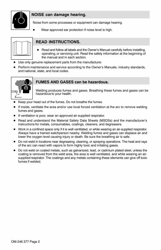
Noise from some processes or equipment can damage hearing.
� Wear approved ear protection if noise level is high.
NOISE can damage hearing.
READ INSTRUCTIONS.
� Read and follow all labels and the Owner’s Manual carefully before installing,operating, or servicing unit. Read the safety information at the beginning ofthe manual and in each section.
� Use only genuine replacement parts from the manufacturer.
� Perform maintenance and service according to the Owner’s Manuals, industry standards,and national, state, and local codes.
FUMES AND GASES can be hazardous.
Welding produces fumes and gases. Breathing these fumes and gases can behazardous to your health.
� Keep your head out of the fumes. Do not breathe the fumes.
� If inside, ventilate the area and/or use local forced ventilation at the arc to remove weldingfumes and gases.
� If ventilation is poor, wear an approved air-supplied respirator.
� Read and understand the Material Safety Data Sheets (MSDSs) and the manufacturer’sinstructions for metals, consumables, coatings, cleaners, and degreasers.
� Work in a confined space only if it is well ventilated, or while wearing an air-supplied respirator.Always have a trained watchperson nearby. Welding fumes and gases can displace air andlower the oxygen level causing injury or death. Be sure the breathing air is safe.
� Do not weld in locations near degreasing, cleaning, or spraying operations. The heat and raysof the arc can react with vapors to form highly toxic and irritating gases.
� Do not weld on coated metals, such as galvanized, lead, or cadmium plated steel, unless thecoating is removed from the weld area, the area is well ventilated, and while wearing an air-supplied respirator. The coatings and any metals containing these elements can give off toxicfumes if welded.

OM-246 377 Page 3
SECTION 2 − SPECIFICATIONS
Specification Titanium 7300Helmet Titanium 9400Helmet Titanium 1600 Helmet
Viewing Field 97 x 47 mm(3.81 x 1.85 in)
97 x 60mm(3.81 x 2.62 in)
102 x 102 mm(4 x 4 in.)
Reaction Time 0.0000500 sec (1/20,000) −−
Available Shades Darkened State:No. 8 − No. 13
Light State: No. 3Provides continuous UV and IR protection
Standard: No. 10Available: No. 9 − 13Provides continuousUV and IR protection
Upgradeable to auto-darkening lens
Sensitivity Control Adjusts for varyingambient light and
welding arc−−
Delay Control Slows lens dark-to-light state between 0.1 and1.0 seconds −−
Automatic PowerOff
Shuts lens Off 15−20 minutes after last arc isstruck −−
Low BatteryIndicator
Red LED light illuminates to indicate 2−3 daysremaining battery life −−
Power Supply CR2450 lithium battery (Miller Part No.217 043) −−
Sensors Independent/Redun-dant (Three)
Independent/Redun-dant (Four) −−
OperatingTemperature
14�F to 131�F / −10�C to +55�C
� When stored in extremely cold temperatures,warm helmet to ambient temperature beforewelding.
−−
StorageTemperature
−4�F to 158�F / −20�C to +70�C
� When stored in extremely cold temperatures,warm helmet to ambient temperature beforewelding.
−−
Total Weight 481.9 g (17 oz.) 510.3g (1lb 2oz.) −−
Standards ANSI Z87.1+(2003)and CSA
ANSI Z87.1+(2003)and DIN/CSA/TUV −−
Warranty 2 years from date of purchase (see Section 13)
� The helmets in this manual are covered by one or more of the following patents: U.S. Patent − No. 6,552,316, No. 6,483,090, No. 6,614,409U.S. Patent Application − No. 29/223,100, No. 11/053,977DE. Patent − No. 199 59 944 C2, No. 199 59 945 C2FR. Patent − No. 9916004

OM-246 377 Page 4
SECTION 3 − OPERATING INSTRUCTIONS −TITANIUM 7300 SERIES HELMETS
3-1. Helmet Controls (Titanium 7300 Series Helmets)
SHADE SENSITIVITY
DELAY
The lens on Titanium 7300 Series Hel-mets turns on (darkens) automaticallywhen welding begins and turns offwhen welding stops.
1 Reset Button(See Section 3-2)
2 Low Battery Indicator (See Section 3-2)
3 Variable Shade Control(No. 8 − 13) (See Section 4-5)
4 Sensitivity Control(See Section 4-6)
5 Lens Delay Control (SeeSection 4-4)
1 2 3 4 5
804 815

OM-246 377 Page 5
3-2. Reset Button And Low Battery Indicator(Titanium 7300 Series Helmets)
SHADE SENSITIVITY
DELAY
� The auto-darkening lens onTitanium 7300 Series Helmetsturns on (darkens) automatical-ly when welding begins andturns off when welding stops.
1 Reset Button
Press Reset button to check if thelens is working properly.
When the Reset button is pressed,the lens should darken twice and re-turn to the clear state. Do not usethe helmet if the lens does not func-tion as described. (See Section 11,Troubleshooting.)
2 Low Battery Indicator
The low battery indicator lightswhen 2−3 days of battery life re-main.
If battery power is low, replace withCR2450 lithium battery (Miller PartNo. 217 043) (see Section 12).
804 815
1 2
3-3. Lens Delay Control (Titanium 7300 Series Helmets)
SHADE SENSITIVITY
DELAY
1 Lens Delay Control
The lens delay control is used toadjust the time for the lens to switchto the clear state after welding.
The delay is particularly useful ineliminating bright after-rays pres-ent in higher amperage applica-tions where the molten puddle re-mains bright momentarily afterwelding. Adjusts from slow to fast.
804 815
1

OM-246 377 Page 6
3-4. Variable Shade Control (No. 8 − 13) (Titanium 7300 Series Helmets)
SHADE SENSITIVITY
DELAY
1 Variable Shade Control(No. 8 − 13)
Use the control to adjust the lensshade in the darkened state. Usethe table below to select propershade control setting based onyour welding process.
Start at shade 12 and adjust lighterto suit the welding application andyour personal preference.
804 815
1
Application Welding Arc Current in Amperes Protective Shade No.
Stick Electrodes Less than 4040−8080−175175−300300−500
910111213
MIG Less than 100100−175175−300300−500
10111213
Gas Tungsten Arc Welding(TIG)
Less than 5050−100100−200200−400
10111213
Air Carbon Less than 500500−700
1213
Plasma Arc Cutting 60−150150−250250−400
111213
Plasma Arc Welding Less than 5050−200200−400
91012

OM-246 377 Page 7
3-5. Sensitivity Control (Titanium 7300 Series Helmets)
SHADE SENSITIVITY
DELAY
1 Sensitivity Control
Weld Mode
Use control to make the lens more respon-sive to different light levels in various weld-ing processes. Use a Mid-Range or30−50% sensitivity setting for most ap-plications.
It may be necessary to adjust helmet sensi-tivity to accommodate different lighting con-ditions or if lens is flashing On and Off. Ad-just helmet sensitivity as follows:
� Adjust helmet sensitivity in lighting con-ditions helmet will be used in.
� Turn sensitivity control to lowest set-ting.
� Press Reset button to turn helmet On.Helmet lens will darken twice and thenclear.
� Face the helmet in the direction of use,exposing it to the surrounding light con-ditions.
� Gradually turn sensitivity setting clock-wise until the lens darkens, then turnsensitivity control counterclockwiseuntil slightly past setting where lensclears. Helmet is ready for use. Slightreadjustment may be necessary forcertain applications or if lens is flashingon and off.
Grind Mode
� Do not weld in the Grind mode; the lenswill not darken.
To use the Grind mode, turn the Sensitivitycontrol counterclockwise to the far left posi-tion (Grind). To resume welding, return thecontrol to the desired sensitivity setting.
804 815
1
Recommended Sensitivity Settings
Stick Electrode Mid-Range
Short Circuiting (MIG) Low/Mid-Range
Pulsed & Spray (MIG) Mid-Range
Gas Tungsten Arc (TIG) Mid/High-Range
Plasma Arc Cutting/Welding Low/Mid-Range
OM-246 377 Page 8
SECTION 4 − OPERATING INSTRUCTIONS −TITANIUM 9400 SERIES HELMETS
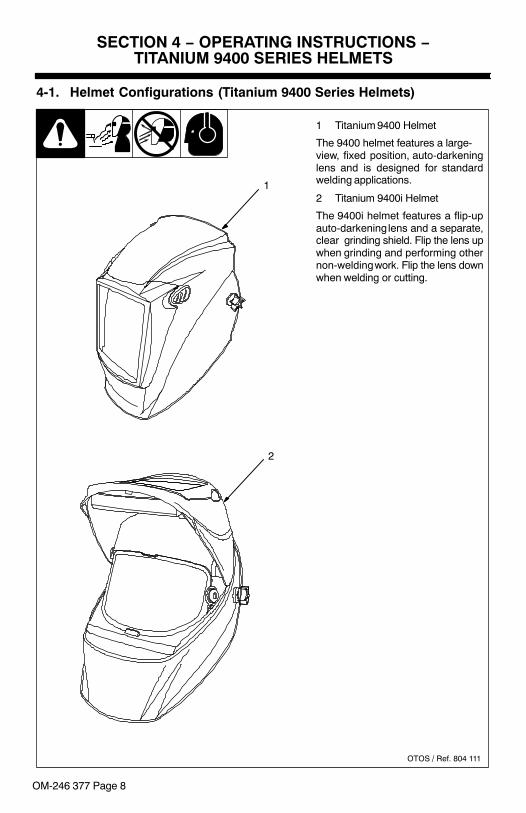
4-1. Helmet Configurations (Titanium 9400 Series Helmets)
1 Titanium 9400 Helmet
The 9400 helmet features a large-view, fixed position, auto-darkeninglens and is designed for standardwelding applications.
2 Titanium 9400i Helmet
The 9400i helmet features a flip-upauto-darkening lens and a separate,clear grinding shield. Flip the lens upwhen grinding and performing othernon-welding work. Flip the lens downwhen welding or cutting.
OTOS / Ref. 804 111
1
2

OM-246 377 Page 9
4-2. Helmet Controls (Titanium 9400 Series Helmets)
1 Reset Button (See Section 4-3)
2 Low Battery Indicator (See Section 4-3)
3 Variable Shade Control (SeeSection 4-5)
4 Sensitivity Control(See Section 4-6)
5 Lens Delay Control(See Section 4-4)
12 34 5
OTOS
OM-246 377 Page 10
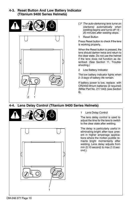
4-3. Reset Button And Low Battery Indicator(Titanium 9400 Series Helmets)
� The auto-darkening lens turns on(darkens) automatically whenwelding begins and turns off 15 −20 minutes after welding stops.
1 Reset Button
Press Reset button to check if the lensis working properly.
When the Reset button is pressed, thelens should darken twice and return tothe clear state. Do not use the helmetif the lens does not function as de-scribed. (See Section 11, Trouble-shooting.)
2 Low Battery Indicator
The low battery indicator lights when2−3 days of battery life remain.
If battery power is low, replace withCR2450 lithium batteries (2 required)(Miller Part No. 217 043) (see Section8).
12
4-4. Lens Delay Control (Titanium 9400 Series Helmets)
1 Lens Delay Control
The lens delay control is used toadjust the time for the lens to switchto the clear state after welding.
The delay is particularly useful ineliminating bright after-rays pres-ent in higher amperage applica-tions where the molten puddle re-mains bright momentarily afterwelding. Lens delay adjusts frommin (0.10 second) to max (1.0 sec-ond.).
1
OM-246 377 Page 11
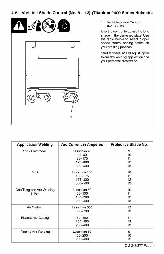
4-5. Variable Shade Control (No. 8 − 13) (Titanium 9400 Series Helmets)
1 Variable Shade Control(No. 8 − 13)
Use the control to adjust the lensshade in the darkened state. Usethe table below to select propershade control setting based onyour welding process.
Start at shade 12 and adjust lighterto suit the welding application andyour personal preference.
1
Application Welding Arc Current in Amperes Protective Shade No.
Stick Electrodes Less than 4040−8080−175175−300300−500
910111213
MIG Less than 100100−175175−300300−500
10111213
Gas Tungsten Arc Welding(TIG)
Less than 5050−100100−200200−400
10111213
Air Carbon Less than 500500−700
1213
Plasma Arc Cutting 60−150150−250250−400
111213
Plasma Arc Welding Less than 5050−200200−400
91012

OM-246 377 Page 12
4-6. Sensitivity Control (Titanium 9400 Series Helmets)
1 Sensitivity Control
Weld Mode
Use control to make the lens more respon-sive to different light levels in various weld-ing processes. Use a Mid-Range or30−50% sensitivity setting for most ap-plications.
It may be necessary to adjust helmet sensi-tivity to accommodate different lighting con-ditions or if lens is flashing On and Off. Ad-just helmet sensitivity as follows:
� Adjust helmet sensitivity in lighting con-ditions helmet will be used in.
� Turn sensitivity control to lowestsetting.
� Press Reset button to turn helmet On.Helmet lens will darken twice and thenclear.
� Face the helmet in the direction of use,exposing it to the surrounding light con-ditions.
� Gradually turn sensitivity setting clock-wise until the lens darkens, then turnsensitivity control counterclockwiseuntil slightly past setting where lensclears. Helmet is ready for use. Slightreadjustment may be necessary forcertain applications or if lens is flashingon and off.
Grind Mode
� Do not weld in the Grind mode; the lenswill not darken.
To use the Grind mode, turn the Sensitivitycontrol clockwise to the far right position(Grind). To resume welding, return the con-trol to the desired sensitivity setting.
1
Recommended Sensitivity Settings
Stick Electrode Mid-Range
Short Circuiting (MIG) Low/Mid-Range
Pulsed & Spray (MIG) Mid-Range
Gas Tungsten Arc (TIG) Mid/High-Range
Plasma Arc Cutting/Welding Low/Mid-Range
Grind Mode Grind Position − Far Right (Clockwise)
OM-246 377 Page 13
SECTION 5 − OPERATING INSTRUCTIONS −TITANIUM 1600 SERIES HELMETS
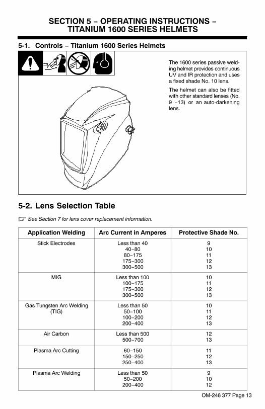
5-1. Controls − Titanium 1600 Series Helmets
The 1600 series passive weld-ing helmet provides continuousUV and IR protection and usesa fixed shade No. 10 lens.
The helmet can also be fittedwith other standard lenses (No.9 −13) or an auto-darkeninglens.
5-2. Lens Selection Table
� See Section 7 for lens cover replacement information.
Application Welding Arc Current in Amperes Protective Shade No.
Stick Electrodes Less than 4040−8080−175175−300300−500
910111213
MIG Less than 100100−175175−300300−500
10111213
Gas Tungsten Arc Welding(TIG)
Less than 5050−100100−200200−400
10111213
Air Carbon Less than 500500−700
1213
Plasma Arc Cutting 60−150150−250250−400
111213
Plasma Arc Welding Less than 5050−200200−400
91012

OM-246 377 Page 14
SECTION 6 − ADJUSTING HEADGEAR
� There are four headgear adjust-ments: headgear top, tightness,angle adjustment, and distanceadjustment.
1 Headgear Top
Adjusts headgear for proper depthon the head to ensure correct bal-ance and stability.
2 Headgear Tightness
To adjust, push in the adjusting knoblocated on the back of the headgearand turn left or right to desired tight-ness.
� If adjustment is limited, it may benecessary to remove the com-fort cushion.
3 Distance Adjustment
Adjusts the distance between theface and the lens. To adjust, loosenboth outside tension knobs andpress inward to free from adjustmentslots. Move forward or back to de-sired position and retighten. (Bothsides must be equally positioned forproper vision.)
4 Angle Adjustment
Four pins on the right side of theheadband top provide adjustmentfor the forward tilt of the helmet. Toadjust, loosen the right outside ten-sion adjustment knob then lift on thecontrol arm tab and move it to the de-sired position. Retighten tension ad-justment knob.
� When using the back distanceadjustment positions, only theback three angle adjustmentpins can be used.
804 118
1
2
3
4

OM-246 377 Page 15
SECTION 7 − REPLACING THE GRINDING SHIELD ORLENS COVERS
7-1. Replacing Grinding Shield On 9400i Helmet
Ref. 804 109
! Never use the auto-dark-ening lens without the in-side and outside lenscovers properly installed.Welding spatter will dam-age the auto-darkeninglens and void thewarranty.
1 Grinding Shield
2 Retaining Clip
3 Tab
Rotate both retaining clips to theOpen position.
Gently push shield toward bot-tom tab and remove shield fromhelmet.
Remove retaining clips fromshield. Install clips in same loc-ation on new shield. (Retainingclips are not interchangeable.)
Install new shield in helmet androtate clips to the Lock position.
1 2
3

OM-246 377 Page 16
7-2. Replacing Lens Covers On Quick Release Helmets
! Never use the auto-dark-ening lens without the in-side and outside lenscovers properly instal-led. Welding spatter willdamage the auto-darken-ing lens and void the war-ranty.
Outside Lens Cover
1 Lens Holder
2 Release Points
3 Outside Lens Cover
Remove lens holder by press-ing release points and pullingthe holder away from the hel-met.
Remove lens cover from hold-er. Replace lens cover in lensholder. Reinstall lens holder inhelmet.
Inside Lens Cover
4 Gasket
5 Plate
6 Lens
7 Inside Lens Cover
Remove the inside lens coverby prying cover from groove ingasket.
Replace the lens cover by gent-ly bowing it in the center and in-serting it, one end at a time, intothe gasket.
� Be sure the cover lens isseated properly (flat) toprevent fogging.
804 814 / 804 816 / OTOS
1 22
3
45
6
7
OM-246 377 Page 17
SECTION 8 − REPLACING THE BATTERY(AUTO-DARKENING LENS ASSEMBLIES)
8-1. Replacing The Battery In Titanium 7300 Series Helmets
804 815
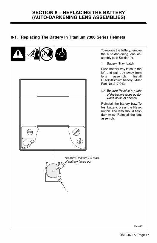
To replace the battery, removethe auto-darkening lens as-sembly (see Section 7).
1 Battery Tray Latch
Push battery tray latch to theleft and pull tray away fromlens assembly. InstallCR2450 lithium battery (MillerPart No. 217 043).
� Be sure Positive (+) sideof the battery faces up (to-ward inside of helmet).
Reinstall the battery tray. Totest battery, press the Resetbutton. The lens should flashdark twice. Reinstall the lensassembly.
1
+
Be sure Positive (+) sideof battery faces up.
OM-246 377 Page 18
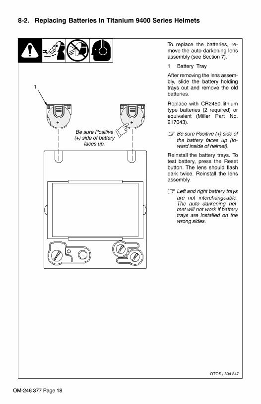
8-2. Replacing Batteries In Titanium 9400 Series Helmets
To replace the batteries, re-move the auto-darkening lensassembly (see Section 7).
1 Battery Tray
After removing the lens assem-bly, slide the battery holdingtrays out and remove the oldbatteries.
Replace with CR2450 lithiumtype batteries (2 required) orequivalent (Miller Part No.217043).
� Be sure Positive (+) side ofthe battery faces up (to-ward inside of helmet).
Reinstall the battery trays. Totest battery, press the Resetbutton. The lens should flashdark twice. Reinstall the lensassembly.
� Left and right battery traysare not interchangeable.The auto−darkening hel-met will not work if batterytrays are installed on thewrong sides.
OTOS / 804 847
+ +
1
Be sure Positive(+) side of battery
faces up.

OM-246 377 Page 19
SECTION 9 − INSTALLING OPTIONAL MAGNIFYING LENS
1 Optional Magnifying Lens
Starting at the bottom, slide magni-fying lens into the helmet retainingbrackets. Align the magnifying lenswith the auto-darkening lens as-sembly.
� Remove lens holding frame(with auto-darkening lens)from helmet shell.
� Remove auto-darkeninglens from lens holder.
� Position lens holder withmagnifying lens holdingtabs facing toward you.From the bottom up, slidemagnifying lens into posi-tion. (Slide magnifying lensup or down slightly as de-sired.)
� Reinstall the auto-darkeninglens in the lens holder.
� Reverse procedure to re-move magnifying lens.
� To prevent lens fogging, installflat side of magnifying lens to-ward auto-darkening lens.
804 818
1
SECTION 10 − MAINTENANCE
NOTICE − Never use solvents or abrasive cleaning detergents.
NOTICE − Do not immerse the lens assembly in water.
The helmet requires little maintenance. However, for best performance cleanafter each use. Using a soft cloth dampened with a mild soap and water solution,wipe the cover lenses clean. Allow to air dry. Occasionally, the filter lens andsensors should be cleaned by gently wiping with a soft, dry cloth.

OM-246 377 Page 20
SECTION 11 − TROUBLESHOOTING
Trouble Remedy
Auto lens not ON – auto-lens will not darken mo-mentarily when the Resetbutton is pressed.
Check batteries and verify they are in good condition and installedproperly. Also, check battery surfaces and contacts and clean ifnecessary. Check battery for proper contact and gently adjustcontact points if necessary. This is particularly important if thehelmet has been dropped. Verify left and right battery trays areinstalled on the correct sides.
Not switching – auto-lensstays light and will notdarken when welding.
Stop welding immediately: Press the Reset button if lens is Auto-On type. If lens if Manual-On type, make sure the lens is turnedOn. If power is on, review the sensitivity recommendations andadjust sensitivity. Clean lens cover and sensors of any obstruc-tions. Make sure the sensors are facing the arc; angles of 45� ormore may not allow the arc light to reach the sensors.
Not Switching – auto-lensstays dark after the weldarc is extinguished, or theauto-lens stays dark whenno arc is present.
Fine-tune the sensitivity setting by making small adjustments tothe control by turning it toward the “min” setting. In extreme lightconditions, it may be necessary to reduce the surrounding lightlevels.
Sections of the auto-lensare not going dark, distinctlines separate the light anddark areas.
Stop welding immediately: The auto-lens may be cracked whichcan be caused by the impact of dropping the helmet. Weld spatteron the auto lens may also cause cracking. (The lens may need tobe replaced; most cracked lenses are not covered by warranty).
Switching or Flickering –the auto-lens darkens thenlightens while the weldingarc is present.
Review the sensitivity setting recommendations and increase thesensitivity if possible. Be sure the arc sensors are not beingblocked from direct access to the arc light. Check the lens coverfor dirt and spatter that may be blocking the arc sensors. Increas-ing Lens Delay 0.1 − 0.3 second may also reduce switching.
Inconsistent or lighterauto-lens shading in thedark-state, noticeable onthe outside edges and cor-ners.
Referred to as an angle of view effect, auto-darkening lenseshave an optimum viewing angle. The optimum viewing angle isperpendicular or 90� to the surface of the auto-lens. When thatangle of view varies in the dark-state, welders may notice slightlylighter areas at the outside edges and the corners of the lens. Thisis normal and does not represent any health or safety hazard.This effect may also be more noticeable in applications wheremagnifying lenses are used.

OM-246 377 Page 21
Notes
Work like a Pro!
Pros weld and cut
safely. Read the
safety rules at
the beginning
of this manual.
OM-246 377 Page 22
SECTION 12 − PARTS LISTS
1
2
3456
11
12
13
7
8
9
10
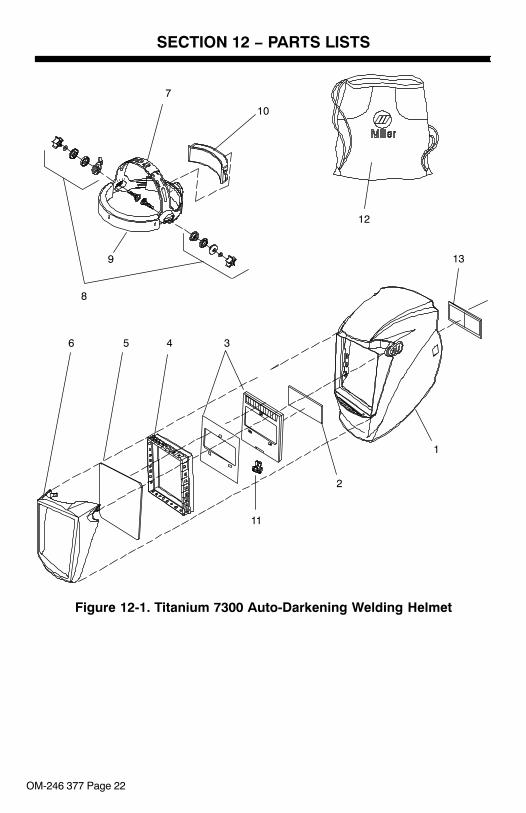
Figure 12-1. Titanium 7300 Auto-Darkening Welding Helmet

OM-246 377 Page 23
DescriptionPartNo.
ItemNo. Quantity
Figure 12-1. Titanium 7300 Auto-Darkening Welding Helmet
1 243 530 Shell, Helmet Titanium (Qr) 1. . . . . . . . . . . . . . . . . . . . . . . . . . . . . . . . . . . . . . . . . . . . 2 770 237 Lens Cover, Inside 4−1/4in X 2in 1. . . . . . . . . . . . . . . . . . . . . . . . . . . . . . . . . . . . . . . 3 245 816 Lens Assembly, Auto−Darkening Titanium 1. . . . . . . . . . . . . . . . . . . . . . . . . . . . . . . 4 245 814 Gasket, Lens Assembly Titanium 7300 1. . . . . . . . . . . . . . . . . . . . . . . . . . . . . . . . . . 5 216 326 Lens Cover, Front 4−11/16in X 5−5/8 in 1. . . . . . . . . . . . . . . . . . . . . . . . . . . . . . . . . 6 243 396 Lens Holder, Titanium (Qr) 1. . . . . . . . . . . . . . . . . . . . . . . . . . . . . . . . . . . . . . . . . . . . . 7 770 246 Headgear, Gray (Includes Items 8 And 9) 1. . . . . . . . . . . . . . . . . . . . . . . . . . . . . . . . 8 *770 248 Kit, Adjustment Angle/Stop Hardware 1. . . . . . . . . . . . . . . . . . . . . . . . . . . . . . . . . . 9 770 249 Headband, Fabric 1. . . . . . . . . . . . . . . . . . . . . . . . . . . . . . . . . . . . . . . . . . . . . . . . . . .
079 975 Replacement O-Rings (For Kit 770 248) (5 Per Pkg.) 1. . . . . . . . . . . . . . . . . . . . . . . . 10 216 336 Comfort Cushion (Foam Rubber) 1. . . . . . . . . . . . . . . . . . . . . . . . . . . . . . . . . . . . . . 11 232 027 Cover, Battery 1. . . . . . . . . . . . . . . . . . . . . . . . . . . . . . . . . . . . . . . . . . . . . . . . . . . . .
217 043 Battery, Lithium (CR2450) 1. . . . . . . . . . . . . . . . . . . . . . . . . . . . . . . . . . . . . . . . . . . . . . . 12 770 250 Bag, Helmet (Miller Logo) 1. . . . . . . . . . . . . . . . . . . . . . . . . . . . . . . . . . . . . . . . . . . .
♦222 003 Adapters, Hard Hat (Not Shown) 1. . . . . . . . . . . . . . . . . . . . . . . . . . . . . . . . . . . . . . . 13 ♦212 235 Lens, 0.75 Magnification 1. . . . . . . . . . . . . . . . . . . . . . . . . . . . . . . . . . . . . . . . . . . 13 ♦212 236 Lens, 1.00 Magnification 1. . . . . . . . . . . . . . . . . . . . . . . . . . . . . . . . . . . . . . . . . . . 13 ♦212 237 Lens, 1.25 Magnification 1. . . . . . . . . . . . . . . . . . . . . . . . . . . . . . . . . . . . . . . . . . . 13 ♦212 238 Lens, 1.50 Magnification 1. . . . . . . . . . . . . . . . . . . . . . . . . . . . . . . . . . . . . . . . . . . 13 ♦212 239 Lens, 1.75 Magnification 1. . . . . . . . . . . . . . . . . . . . . . . . . . . . . . . . . . . . . . . . . . . 13 ♦212 240 Lens, 2.00 Magnification 1. . . . . . . . . . . . . . . . . . . . . . . . . . . . . . . . . . . . . . . . . . . 13 ♦212 241 Lens, 2.25 Magnification 1. . . . . . . . . . . . . . . . . . . . . . . . . . . . . . . . . . . . . . . . . . . 13 ♦212 242 Lens, 2.50 Magnification 1. . . . . . . . . . . . . . . . . . . . . . . . . . . . . . . . . . . . . . . . . . .
* Adjustment Hardware Kit With O-rings.
♦Optional

OM-246 377 Page 24
Miller
12
107
9
8
804 111
1
2
3456
11
13
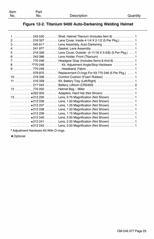
Figure 12-2. Titanium 9400 Auto-Darkening Welding Helmet
OM-246 377 Page 25
DescriptionPartNo.
ItemNo. Quantity
Figure 12-2. Titanium 9400 Auto-Darkening Welding Helmet
1 243 530 Shell, Helmet Titanium (Includes Item 6) 1. . . . . . . . . . . . . . . . . . . . . . . . . . . . . . . . . 2 216 327 Lens Cover, Inside 4-1/4 X 2-1/2 (5 Per Pkg.) 1. . . . . . . . . . . . . . . . . . . . . . . . . . . . . 3 245 817 Lens Assembly, Auto-Darkening 1. . . . . . . . . . . . . . . . . . . . . . . . . . . . . . . . . . . . . . . . 4 241 977 Gasket, Lens Assembly 1. . . . . . . . . . . . . . . . . . . . . . . . . . . . . . . . . . . . . . . . . . . . . . . 5 216 326 Lens Cover, Outside (4-11/16 X 5-5/8) (5 Per Pkg.) 1. . . . . . . . . . . . . . . . . . . . . . . 6 243 396 Lens Holder, Front (Titanium) 1. . . . . . . . . . . . . . . . . . . . . . . . . . . . . . . . . . . . . . . . . . 7 770 246 Headgear Gray (Includes Items 8 And 9) 1. . . . . . . . . . . . . . . . . . . . . . . . . . . . . . . . . 8 *770 248 Kit, Adjustment Angle/Stop Hardware 1. . . . . . . . . . . . . . . . . . . . . . . . . . . . . . . . . . 9 770 249 Headband, Fabric 1. . . . . . . . . . . . . . . . . . . . . . . . . . . . . . . . . . . . . . . . . . . . . . . . . . . .
079 975 Replacement O-rings For Kit 770 248 (5 Per Pkg.) 1. . . . . . . . . . . . . . . . . . . . . . . . . . 10 216 336 Comfort Cushion (Foam Rubber) 1. . . . . . . . . . . . . . . . . . . . . . . . . . . . . . . . . . . . . . 11 216 339 Kit, Battery Tray (Left/Right) 1. . . . . . . . . . . . . . . . . . . . . . . . . . . . . . . . . . . . . . . . . .
217 043 Battery, Lithium (CR2450) 2. . . . . . . . . . . . . . . . . . . . . . . . . . . . . . . . . . . . . . . . . . . . . . . 12 770 250 Helmet Bag − Miller 1. . . . . . . . . . . . . . . . . . . . . . . . . . . . . . . . . . . . . . . . . . . . . . . . .
♦222 003 Adapters, Hard Hat (Not Shown) 1. . . . . . . . . . . . . . . . . . . . . . . . . . . . . . . . . . . . . . . 13 ♦212 235 Lens, 0.75 Magnification (Not Shown) 1. . . . . . . . . . . . . . . . . . . . . . . . . . . . . . . .
♦212 236 Lens, 1.00 Magnification (Not Shown) 1. . . . . . . . . . . . . . . . . . . . . . . . . . . . . . . . . . . ♦212 237 Lens, 1.25 Magnification (Not Shown) 1. . . . . . . . . . . . . . . . . . . . . . . . . . . . . . . . . . . ♦212 238 Lens, 1.50 Magnification (Not Shown) 1. . . . . . . . . . . . . . . . . . . . . . . . . . . . . . . . . . . ♦212 239 Lens, 1.75 Magnification (Not Shown) 1. . . . . . . . . . . . . . . . . . . . . . . . . . . . . . . . . . . ♦212 240 Lens, 2.00 Magnification (Not Shown) 1. . . . . . . . . . . . . . . . . . . . . . . . . . . . . . . . . . . ♦212 241 Lens, 2.25 Magnification (Not Shown) 1. . . . . . . . . . . . . . . . . . . . . . . . . . . . . . . . . . . ♦212 242 Lens, 2.50 Magnification (Not Shown) 1. . . . . . . . . . . . . . . . . . . . . . . . . . . . . . . . . . .
* Adjustment Hardware Kit With O-rings.
♦Optional

OM-246 377 Page 26
123
14
45
6
7
8
912
11
10
13
Figure 12-3. Titanium 9400i Auto-Darkening Welding Helmet

OM-246 377 Page 27
DescriptionPartNo.
ItemNo. Quantity
Figure 12-3. Titanium 9400i Auto-Darkening Welding Helmet
1 245 820 Shell, Helmet Titanium I Series 1. . . . . . . . . . . . . . . . . . . . . . . . . . . . . . . . . . . . . . . . 2 245 819 Clip, Retaining Grinding Shield 2. . . . . . . . . . . . . . . . . . . . . . . . . . . . . . . . . . . . . . . . . 3 245 818 Lens, Grinding Shield (Clear) 1. . . . . . . . . . . . . . . . . . . . . . . . . . . . . . . . . . . . . . . . . . 4 216 327 Lens Cover, Inside 4−3/16in X 2−1/2in 1. . . . . . . . . . . . . . . . . . . . . . . . . . . . . . . . . . 5 245 817 Lens Assembly, Auto−dark Titanium 1. . . . . . . . . . . . . . . . . . . . . . . . . . . . . . . . . . . .
217 043 Battery, Lithium (CR2450) 2. . . . . . . . . . . . . . . . . . . . . . . . . . . . . . . . . . . . . . . . . . . . . . . 6 241 977 Gasket, Lens Assembly Elite (Qr) 1. . . . . . . . . . . . . . . . . . . . . . . . . . . . . . . . . . . . . . 7 216 326 Lens Cover, Front 4−11/16in X 5−5/8in 1. . . . . . . . . . . . . . . . . . . . . . . . . . . . . . . . . . 8 245 815 Lens Holder, Front Titanium I Series 1. . . . . . . . . . . . . . . . . . . . . . . . . . . . . . . . . . . . 9 770 246 Headgear, Gray (Includes Items 10 And 11) 1. . . . . . . . . . . . . . . . . . . . . . . . . . . . . . 10 *770 248 Kit, Adjustment Angle/Stop Hardware Kit 1. . . . . . . . . . . . . . . . . . . . . . . . . . . . . . . 11 770 249 Headband, Fabric 1. . . . . . . . . . . . . . . . . . . . . . . . . . . . . . . . . . . . . . . . . . . . . . . . . . .
079 975 Replacement O-rings For Kit 770 248 (5 Per Pkg.) 1. . . . . . . . . . . . . . . . . . . . . . . . . . 12 216 336 Cushion, Comfort (Foam Rubber) 1. . . . . . . . . . . . . . . . . . . . . . . . . . . . . . . . . . . . . . 13 770 250 Bag, Helmet (Miller Logo) 1. . . . . . . . . . . . . . . . . . . . . . . . . . . . . . . . . . . . . . . . . . . .
♦222 003 Adapters, Hard Hat (Not Shown) 1. . . . . . . . . . . . . . . . . . . . . . . . . . . . . . . . . . . . . . . 14 ♦212 235 Lens, 0.75 Magnification (Not Shown) 1. . . . . . . . . . . . . . . . . . . . . . . . . . . . . . . .
♦212 236 Lens, 1.00 Magnification (Not Shown) 1. . . . . . . . . . . . . . . . . . . . . . . . . . . . . . . . . . . ♦212 237 Lens, 1.25 Magnification (Not Shown) 1. . . . . . . . . . . . . . . . . . . . . . . . . . . . . . . . . . . ♦212 238 Lens, 1.50 Magnification (Not Shown) 1. . . . . . . . . . . . . . . . . . . . . . . . . . . . . . . . . . . ♦212 239 Lens, 1.75 Magnification (Not Shown) 1. . . . . . . . . . . . . . . . . . . . . . . . . . . . . . . . . . . ♦212 240 Lens, 2.00 Magnification (Not Shown) 1. . . . . . . . . . . . . . . . . . . . . . . . . . . . . . . . . . . ♦212 241 Lens, 2.25 Magnification (Not Shown) 1. . . . . . . . . . . . . . . . . . . . . . . . . . . . . . . . . . . ♦212 242 Lens, 2.50 Magnification (Not Shown) 1. . . . . . . . . . . . . . . . . . . . . . . . . . . . . . . . . . .
* Adjustment Hardware Kit With O-rings.
♦Optional

OM-246 377 Page 28
1
2
34567
8
9
10
11
12
13
Figure 12-4. Titanium 1600 Welding Helmet

OM-246 377 Page 29
DescriptionPartNo.
ItemNo. Quantity
Figure 12-4. Titanium 1600 Welding Helmet
1 243 530 Shell, Helmet Titanium (Elite) (Qr) 1. . . . . . . . . . . . . . . . . . . . . . . . . . . . . . . . . . . . . . 2 235 628 Lens Cover, In 4−1/2in X 5−1/4in (Mp−10) 1. . . . . . . . . . . . . . . . . . . . . . . . . . . . . . . . 3 235 630 Filter Plate, #10 4 1/2 X 5 1/4 (Mp−10) 1. . . . . . . . . . . . . . . . . . . . . . . . . . . . . . . . . . . 4 246 759 Aluminum Plate, Titanium 1600 1. . . . . . . . . . . . . . . . . . . . . . . . . . . . . . . . . . . . . . . . 5 245 813 Gasket, Lens Assembly Titanium 1600 1. . . . . . . . . . . . . . . . . . . . . . . . . . . . . . . . . . 6 216 326 Lens Cover, Front 4−11/16in X 5−5/8in 1. . . . . . . . . . . . . . . . . . . . . . . . . . . . . . . . . . 7 243 396 Lens Holder, Titanium Elite (Qr) 1. . . . . . . . . . . . . . . . . . . . . . . . . . . . . . . . . . . . . . . . 8 770 246 Headgear, Gray (Includes Items 9 And 10) 1. . . . . . . . . . . . . . . . . . . . . . . . . . . . . . . 9 *770 248 Kit, Adjustment Angle/Stop Hardware Kit 1. . . . . . . . . . . . . . . . . . . . . . . . . . . . . . . . 10 770 249 Headband, Fabric 1. . . . . . . . . . . . . . . . . . . . . . . . . . . . . . . . . . . . . . . . . . . . . . . . . .
079 975 Replacement O-rings For Kit 770 248 (5 Per Pkg.) 1. . . . . . . . . . . . . . . . . . . . . . . . . . 11 216 336 Cushion, Comfort (Foam Rubber) 1. . . . . . . . . . . . . . . . . . . . . . . . . . . . . . . . . . . . . . 12 770 250 Bag, Helmet (Miller Logo) 1. . . . . . . . . . . . . . . . . . . . . . . . . . . . . . . . . . . . . . . . . . . .
♦222 003 Adapters, Hard Hat (Not Shown) 1. . . . . . . . . . . . . . . . . . . . . . . . . . . . . . . . . . . . . . . 13 ♦212 235 Lens, 0.75 Magnification (Not Shown) 1. . . . . . . . . . . . . . . . . . . . . . . . . . . . . . . .
♦212 236 Lens, 1.00 Magnification (Not Shown) 1. . . . . . . . . . . . . . . . . . . . . . . . . . . . . . . . . . . ♦212 237 Lens, 1.25 Magnification (Not Shown) 1. . . . . . . . . . . . . . . . . . . . . . . . . . . . . . . . . . . ♦212 238 Lens, 1.50 Magnification (Not Shown) 1. . . . . . . . . . . . . . . . . . . . . . . . . . . . . . . . . . . ♦212 239 Lens, 1.75 Magnification (Not Shown) 1. . . . . . . . . . . . . . . . . . . . . . . . . . . . . . . . . . . ♦212 240 Lens, 2.00 Magnification (Not Shown) 1. . . . . . . . . . . . . . . . . . . . . . . . . . . . . . . . . . . ♦212 241 Lens, 2.25 Magnification (Not Shown) 1. . . . . . . . . . . . . . . . . . . . . . . . . . . . . . . . . . . ♦212 242 Lens, 2.50 Magnification (Not Shown) 1. . . . . . . . . . . . . . . . . . . . . . . . . . . . . . . . . . .
* Adjustment Hardware Kit With O-rings.
♦Optional
SECTION 13 − LIMITED WARRANTY
LIMITED WARRANTY – Subject to the terms and conditions below. MillerElectric Mfg. Co., Appleton, Wisconsin, warrants to its original retail pur-chaser that the new Miller equipment sold after the effective date of thislimited warranty is free of defects in material and workmanship at the timeit is shipped by Miller. THIS WARRANTY IS EXPRESSLY IN LIEU OF ALLOTHER WARRANTIES, EXPRESS OR IMPLIED, INCLUDING THEWARRANTIES OR MERCHANTABILITY AND FITNESS.
Miller Elite Series auto-darkening lens helmets are warranted for 2 yearsfrom the date of purchase. Proof of purchase is required for warrantytransactions so it is imperative that a copy of the original invoice or salesreceipt be retained.
For warranty transactions, contact your Miller Distributor.
Effective January 1, 2010

ORIGINAL INSTRUCTIONS − PRINTED IN USA © 2010 Miller Electric Mfg. Co.
Visit our website at
www.MillerWelds.com
®
Miller Electric Mfg. Co.An Illinois Tool Works Company1635 West Spencer StreetAppleton, WI 54914 USA