
AUTO-CURTAIN - palsusa.compalsusa.com/wp-content/uploads/2015/11/ATNEWELL-MANUAL-pneg4… · Auto...
48
Model 511 AUTO-CURTAIN INSTALLATION & INSTRUCTION MANUAL Base Models: 506, 507, & 511 Options Include: gearbox, aluminum drum size, and sprocket drive. Owner’s Manual Manual # PNEG-472 12-15-04 PNEG-472
Transcript of AUTO-CURTAIN - palsusa.compalsusa.com/wp-content/uploads/2015/11/ATNEWELL-MANUAL-pneg4… · Auto...

Model 506S
Model 511
AUTO-CURTAININSTALLATION & INSTRUCTIONMANUALBase Models: 506, 507, & 511Options Include: gearbox, aluminum drum size, andsprocket drive.
Owner’s ManualManual # PNEG-47212-15-04
PNEG-472

Auto Curtain
2

Auto Curtain
3
Table of Contents
Safety .....................................................................................4-7Options & Descriptions.........................................................8Information .............................................................................9-11Installing Bracket Assembly .................................................12Installation..............................................................................13Mounting ................................................................................14-22Wiring Diagrams ....................................................................23-25Setting Limit Switch Kit .........................................................26Reverse Operation Instructions ...........................................27Setting Timers ........................................................................28-29Parts Breakdown ...................................................................30-41Troubleshooting ....................................................................42-45Warranty .................................................................................46
Auto Curtain
4
SAFETY FIRSTGeneral Safety Statements
The GSI Group Inc’s Principal concern isyour safety and the safety of others associ-ated with grain handling equipment. Wewant to keep you as a customer. Thismanual is to help you understand safeoperating procedures and some problemswhich may be encountered by the operatorand other personnel. As owner and/or operator, it is your re-sponsibility to know what requirements,hazards and precautions exist and inform allpersonnel associated with, or in the area ofthe equipment. Safety precautions may berequired from the personnel. Avoid andalteration to the equipment. Such alter-ations may produce a very dangeroussituation, where serious injury or death mayoccur.
SAFETY ALERT SYMBOL
The symbol shown isused to call your attention
to instructions concerning your personalsafety. Watch for this symbol; as it pointsout important safety precautions. Itmeans “ATTENTION,” WARNING,” “CAU-TION,” and “DANGER.” Read the mes-sage that follows and be cautious to thepossibility of personal injury or death.
The GSI Group Inc. recommends that youcontact your local power company and havea representative review your installation soyour wiring will be compatible with theirsystem and so that you will have adequatepower supplied to your unit.
BE ALERT!Danger!
Personnel operating orworking around electri-
cal equipment should read this manual.This manual must be delivered withequipment to its owner. Failure to readthis manual and its safety instructions is amisuse of the equipment.
This product is intended for the use ofcontrolling the curtain only. Any other use isa misuse of the product!
This product has sharpedges! These sharp edgesmay cause serious injury. Toavoid injury handle sharp
edges with caution and use proper protec-tive clothing and equipment at all times.
The safety pages that follow are to showyou where you can find the safety decals.The photographs show exactly where thedecals should be. If a decal has beendamaged or is missing contact The GSIGroup, Inc. for a free replacement.
Safety

Auto Curtain
5
Safety
DC-995 is located onthe belt gaurd and onthe electrical box.
DC-644 is located on thefront of the electrical boxlid.
DC-995
SHEAR POINTKeep hands clear of movingparts. Do not operate withguard removed. Disconnectand lockout power beforeservicing.
WARNING

Auto Curtain
6
Safety
DC-945 is located inside theelectrical box.
DC-946 is located inside theelectrical box.
DC-995 is locatedon the top of theelectrical box.
DC-889 is located onthe top of the and in-side the electrical box.
DC-995
SHEAR POINTKeep hands clear of movingparts. Do not operate withguard removed. Disconnectand lockout power beforeservicing.
WARNING

Auto Curtain
7
Safety
Moving parts cancrush and cut.Keep hands clear ofdrum and cables.
WARNING
DC857
WARNING
DC856
Moving parts cancrush and cut.Keep hands clear ofsprocket and chain.
DC-5376 is located on the cover ofthe drum gaurd.
DC-857 or DC-856 islocated on the drumcover.
Machines which use asprocket and chain inplace of the drum andcable use DC-856 inplace of DC-857.
DC-857 or DC-856are also found un-derneath the drumgaurd mounted onthe frame. Thisprecautionart mea-sure was taken inthe event that thegaurd is removed.

Auto Curtain
8
Options & Descriptions
Options & Descriptions
Options Available
Timers:
5 Minute Nonadjustable Timer (1738) OPEN 1:10 run time, 3:50 pause time.CLOSE 2:00 run time, 3:00 pause time.
5 Minute Adjustable Timer (1737) Ability to set variable run/pause timesduring oper/close mode.
Gearboxes: *Distance travel on a direct pull.
"SLOW GEARBOX" 1200:1 (1333-12) *4" travel per minute
"FAST GEARBOX" 200:1 (1333-2) *24" travel per minute
Aluminum Drums:
1 5/8" Aluminum Drum (1121) 9 1/2' of cable pull per side of drum
2 3/4" Aluminum Drum (1122) 12 1/2' of cable pull per side of drum

Auto Curtain
9
Model 506 Information
Timer Model 506 has a four circuit nonadjust-able 5 minute timer. This timer is preset atthe factory. When the 506 is opening thecurtains, it will run for 1 minute 10 secondsand pause for 3 minutes 50 seconds. Whenthe 506 is closing the curtains, it will run for2 minutes and pause for 3 minutes. If thethermostat is not satisfied after one cycleduring open / close, the timer will repeat therun / pause times until the thermostat issatisfied or the upper / lower limit switch isdepressed.
Hour Timer Switches - Positive Ventila-tion The hour timer switches are used prima-rily in the cooler months to allow positiveventilation / fresh air into the confinementhouse. The 506 has two positive ventilationcontrol switches. These switches arelocated outside of the control box on the lefthand side. When these switches are down,the positive ventilation mode is off. Whenone switch is up / on (it does not matterwhich switch), once an hour the machinewill disregard the temperature and will runthe curtains down for 1 minute allowingfresh air into the house. After the 1 minuterun time, the machine will go back intoautomatic mode. The machine will not rununtil the thermostat tells the machine that itis too cool in the barn. When both switchesare up / on, every 30 minutes the machinewill disregard the temperature and run thecurtains down for 1 minute. After the 1minute run time, the machine will go backinto automatic mode.
Model 511 Information
No Timer The 511 machine is ideal for use with anintegrated ventilation control because it hasno internal timing mechanism. The 511 istotally dependent on an outside source totell the machine when to raise or lower thecurtains automatically. This machine alsohas the ability to be operated manually andcomes standard with a fan turn on / offswitch (latch-out switch).
Model 507 Information
Timer Model 507 has a two circuit 5 minuteadjustable timer. The timer allows theopening and closing times of the curtain tobe customized in 2.5 second increments.There are two cams for adjustment. Theupper cam controls the opening run / pausetimes and the lower cam controls the clos-ing run / pause times. (SEE PAGE 11,12FOR TIMER ADJUSTMENT)
Rapid Close Function The rapid close function is beneficialduring the spring and fall when there israpid temperature change in the evenings.The rapid close function will alleviate thechill on the livestock by speeding up thetime it takes for the curtains to close. The rapid close is controlled by the singletoggle switch located outside of the controlbox on the left hand side. When this switchis down, the rapid close function is off.When this switch is up / on and the thermo-stat signals the machine to close, the timeris bypassed and the machine will continu-ously run closed. The machine will stopclosing only if the thermostat is satisfied orthe upper limit switch is depressed.
Information

Auto Curtain
10
Auto-Curtain Information
Thermostat To regulate the temperature within a confine-ment house while using an Auto Curtain Model506 or 507, it is recommended that a 2 stagethermostat is used. The temperature at whichyou set the thermostat determines the amountof ventilation in relation to the temperature of thehouse. When the room temperature is within+/- 1°F the thermostat setting, the machine willstop the curtain movement until the ambienttemperature changes. Follow your field manag-ers recommendations for thermostat settings. The location of the thermostat is very impor-tant. Never place the thermostat in directsunlight, close to a radiant heater or near thedirect output of a convective heater. If thethermostat is near a heat source, false roomtemperatures may be detected. False roomtemperatures may be detected if the thermostatis mounted near an outer wall or near a draft.The ideal location is near the center of the roomjust above the livestock yet out of their reach.
Fan Turn ON / OFF Switch (Latch-outSwitch) The fan turn on / off switch kit (AC1568)allows the on / off operation of another piece ofventilation equipment. For example, a fan canbe controlled by this switch during tunneloperation. Switch kit AC1568 can be used on anymodel of Auto-Curtain Machine. AC1538 doescome standard with Model 511.
Shear Pin The Auto-Curtain Machines have a shear pinwhich will shear if exceptional strain occurs.The shear pin (#1342) is located where thegearbox and drive shaft are connected. NOTE:If the shear pin shears, it will be necessaryto replace it and readjust the limit switches.Be sure to locate the cause of the strain andcorrect the problem, otherwise the new pinwill shear also.
Cables and Curtains The cable and curtains need to move freelywithout obstructions, such as: cable clampsfrom splices dragging over pulleys, brackets,and rafters. Cable should be periodicallychecked for excessive wear or kinks where thecable is running around pulleys and throughbrackets. When replacing cable, all of thepulleys should be checked for wear. Pulleyswith flat spots, grooves, or excessive wearshould be replaced. Counter weights that areused on the main line cable should also movefreely and not drag or hang-up. If the screenwire is not flush with the board on the top of theopening, slide-over guides can be installed tomake sure the curtain does not hang up on theboard. Note: If a splice is made in the cablebetween any brackets, use three cableclamps to fasten the two pieces together.Make sure there is enough travel for theclamps to stay out of the pulleys.
Brackets and Pulleys The AC1821 bracket assembly (see Fig. 1pg. 8) should be mounted by through bolting thebracket onto a beam or some other solid foun-dation. The bracket mounts directly over thecenter of the grooved drum on the machine (seeFig. 2 pg. 8 ), with (4) 7" (17.78cm) bolts sup-plied in the installation kit. The AC1821 brackethandles more load than any other bracket onthe building, so it is critical that it is mountedcorrectly. Moving pulleys need to be positionedso that they do not come in contact with otherpulleys, brackets, or any other object.
Counter Weights Counter weights provide tension on the cablesystem and keep the cables in the pulleystrack. The location of the machine determineswhere the counter weights are located. (SeeFig. 9 pg. 16).
Information

Auto Curtain
11
2
1
3
Auto-Curtain InformationHand Winches Hand winches can be used in conjunctionwith the Auto-Curtain Machines to raise andlower the curtains when they are configured intothe main line cable system. The hand winchesare used primarily as a precautionary measureduring power failure. When power is notpresent, the Auto-Curtain Machines will notwork. The hand winches can be operatedmanually to ventilate the confinement house.
Do not use the hand winchesunless in an emergency.
When the hand winch is used, the Auto-Curtain Machine actuator will not move eventhough the curtains are moving. After the handwinch is used, the limit switches must bereadjusted. If the switches are not readjusted,the curtain may be at a different position thanthe limit switches were set for. This can allowthe curtain to be pulled too tight. If the hand winches are used, the curtains willneed readjusted for the limit switch position.First, make sure the curtain is all the way down.Next, raise the curtain with the machine inmanual mode until the upper limit switch isdepressed or the curtain clears the top of theopening. Then, move the curtain with the handwinch until the reinforcement rod just clears thetop of the curtain opening and make sure theupper limit switch is depressed. The limit switchis now readjusted.
It is important that the curtain is notraised too high and pulled tight. When curtainsare pulled too tight, the work load of the Auto-Curtain increased substantially.
LIMIT SWITCHES There are (2) limit switches located nearthe bottom of the Auto-Curtain control box.These adjustable switches stop the Auto-Curtain from advancing past the upper andlower limits set by the user. (See FIG. 3 pg. 9to set limits) Either switch is activated by theactuator 2 that travels on the drive shaft 3 .When the actuator depresses the switch, themachine stops.
An upper limit switch that is set too high canallow the curtains to be pulled too tight. Whenthis happens, the load on the machine is in-creased significantly and can cause the shearpin to shear, break rafters, cables, or pulleys.
A lower limit that is set too low can allow thecable to unwind off of the aluminum rum. Whenthis happens, the cables do not always settleback into the appropriate grooves and the cablecan wind on top of itself.
It is important that the cables wind onto thealuminum drum in a consistent fashion. Bywinding correctly, the limit switch settingsalso remain accurate.
Information

Auto Curtain
12
Mount the 1902AA pulleys to theAC1821 bracket directly left andright of the center holes in thebracket (see Fig. 1). This willhelp the cable wrap around thegrooved drum in a single layerand reduce the chance of thecable binding. The 1902AApulleys have grease inserts inthem for periodic maintenance,make sure they are accessible.
Mount the AC1821 bracketassembly so that the grooveddrum is directly below the mid-point of the two pulleys see (Fig.2). This assures that the cable iswound properly onto the drumand does not overlap itself. Theideal position would have thecables directly vertical, with allthe necessary cable to close thecurtains completely wound onthe grooved drum. Greaseshould be applied to the cablethat wraps around the grooveddrum at least once every threemonths. Cables should beinspected periodically for evi-dence of wear or damage.
It is recommended that thebracket be mounted to a 4 x 4 orsome other solid part of theframe. Use (4) 7" (17.78cm)boltssupplied in the installation kit,through the frame to mount thebracket (see Fig. 7 pg. 14).DO NOT USE LAG BOLTS!
Installing the AC1821Bracket Assembly
CENTER HOLES
1902AA
GREASE INSERT
AC1821
Fig. 1
Caution: Keephands and cloth-ing clear of drumand cable.
CABLES
CENTERLINE
Fig. 2
Installing Bracket Assembly

Auto Curtain
13
ALWAYS DISCONNECT AND LOCKOUT POWER BEFORE WORKINGON OR AROUND THE MOTOR.
Installation Instructions
When mounting your Auto-Curtain it is importantto use a solid surface on the building. It isrecommended that two (wooden) 2 x 4's (2inches x 4 inches) are used directly behind thebase of the machine to provide a flat surface.The machine should be secured to the buildingusing (4) full threaded rods and large washerssupplied in the installation kit, these rods shouldgo through the holes in the frame of the ma-chine, (wooden) 2 x 4's, 4 x 4 (4 inches x 4inches), or other solid frame components of thebuilding. For remaining holes a (wooden) 2 x10 (2 inches x 10 inches) brace can bemounted inside the building across the wall tobolt through if needed. DO NOT USE LAGBOLTS TO MOUNT THE MACHINE!
Drill holes through wall to insert electrical wiresfrom Auto-Curtain to inside of building; insulateto comply with electrical codes.
It may be necessary to add extra supportbeams to your building to ensure a solid installa-tion. For example (see Fig.7) an extra 4 x 4was added to support the machine. On an endinstallation a beam off of the building may berequired to install the machine.
It is also recommended that the machine bemounted 24"- 48" from the bottom of the ma-chine to the ground. This enables easy accessfor maintenance and prevents moisture prob-lems. The machine should not be mounted onor close to the ground, water buildup couldshorten the life of the machine or cause failure.Building a shelter over the motor and controlbox may be required to shield these compo-nents from the weather. This can be
Caution: Extra care must be takenwhile operating the Auto-Curtain,before the upper and lower limit
switches are set correctly. Also, the cablesystem and pulleys need to be checked forobstructions before operating the machine.
12
done by using tin and two pieces of lumber, andleaning over the machine.
Before splicing into the main cable, check thelocation of the actuator (1) on the drive shaft (2).The actuator should be on the far right side ofthe drive shaft. If not, run the machine inmanual mode, it may be necessary to move theweld nut and limit switch first, until the actuatoris in the correct position. Now the cables canbe spliced. Next, set the limit switches (seepage 9).
Installation

Auto Curtain
14
24" - 48"
truss
center lineExtra 4 x 4 addedto mount machine
4 x 4' s on 5' centers
1 x 's and siding
18"
AC1821 mounted directly to 4 x 4with (4) 7" bolts & large washers(see Fig. 2 for proper positioning ofbracket)
Mounting Recommendations forCenter House Installation (Outside)
Fig. 3
2 x 4 's Used to mount themachine against the siding Mount the Curtain Machine with (4)
full thread rods & large washersthrough 4 x 4's, 1 x 's , and siding formaximum support
Mounting

Auto Curtain
15
Bas
ic C
ente
r In
stal
lati
on
Pu
llin
g O
ne
Sid
e o
f th
e H
ou
se
Fig
. 4
NO
TE:
We
Reco
mm
end
any
Build
ing
Ove
r 380
Fee
t Sho
uld
have
a C
urta
in M
achi
ne fo
r Eac
h Si
de o
f the
Hou
se.
Cur
tain
Cou
nter
Wei
ght
AC
1822
AC
1822
Mai
n C
able
Sm
all P
last
icP
ulle
y (#
3500
30)
Nyl
on R
etai
ner C
ord
Mai
n C
able
AC
1821
(see
Fig
. #7
for I
nsta
llatio
n)
Sm
all P
last
icP
ulle
y (#
3500
30)
Tie
d of
f to
Bar
Pol
y-co
rd T
ied
off
to M
ain
Cab
le
Mounting

Auto Curtain
16
Run
the
cabl
e th
roug
h th
e ey
ebol
t on
the
coun
ter
wei
ght a
nd ti
e it
off t
o a
trus
s. T
his
will
sto
p th
e co
unte
rwei
ght f
rom
spi
nnin
g an
d tw
istin
g ca
usin
g th
e ca
ble
to m
isal
ign.
Inst
alla
tio
n th
e C
ou
nte
r W
eig
hts
Fig
. 5
Mounting

Auto Curtain
17
(#35
-003
0) P
ulle
y
Pol
y-co
rd
Mai
n C
able
Atta
ched
Sec
ured
to B
uild
ing
Sp
acin
g th
e S
mal
l Lif
t Pu
lley
Fig
. 6
Tak
e th
e he
ight
of t
he c
urta
in a
nd a
dd 6
", th
is w
ill b
e th
esp
ace
need
ed fo
r the
tied
off
poly
-cor
d to
trav
el fr
eely
.
Atta
ch th
e po
ly-c
ord
to th
e m
ain
cabl
e, w
hen
the
curt
ain
isfu
lly d
own,
the
poly
-cor
d is
atta
ched
1"-
3" in
fron
t of t
hepu
lley.
Mounting

Auto Curtain
18
AC
1820
AC
1822
May
be
Mou
nted
Eith
er P
lace
Cab
le S
plic
ed U
sing
3 C
able
Cla
mps
AC
1821
Bas
ic E
nd
Inst
alla
tio
nP
ulli
ng
Bo
th S
ides
of
the
Ho
use
Fig
. 7
Som
e en
d in
stal
latio
nsw
ill re
quire
an
extr
a po
stto
mou
nt th
e cu
rtai
nm
achi
ne.
The
pos
t will
prov
ide
extr
a su
ppor
t.
Mounting

Auto Curtain
19
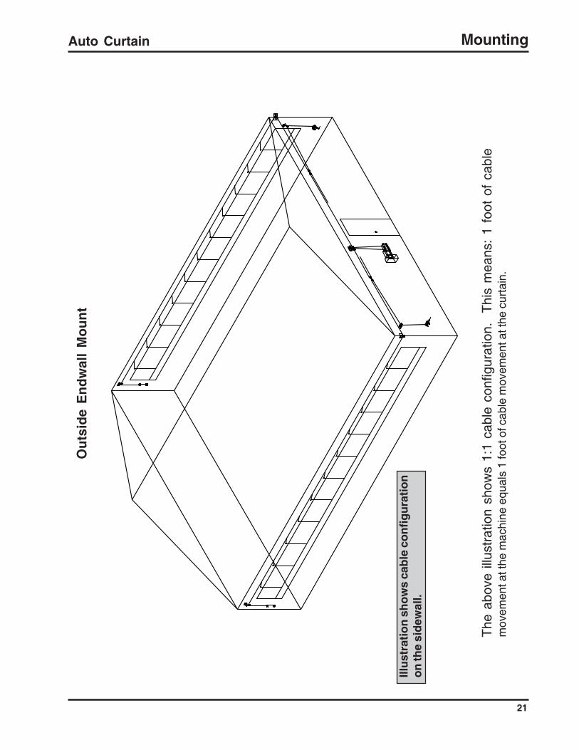
Ou
tsid
e E
nd
wal
l M
ou
nt
The
abo
ve i
llust
ratio
n sh
ows
1:2
cabl
e co
nfig
urat
ion.
T
his
mea
ns:
1 fo
ot o
f ca
ble
mov
emen
t at t
he m
achi
ne e
qual
s 2
feet
of c
able
mov
emen
t at t
he c
urta
in.
Mounting

Auto Curtain
20
Ou
tsid
e E
nd
wal
l M
ou
nt
The
abo
ve i
llust
ratio
n sh
ows
1:1
cabl
e co
nfig
urat
ion.
T
his
mea
ns:
1 fo
ot o
f ca
ble
mov
emen
t at t
he m
achi
ne e
qual
s 1
foot
of c
able
mov
emen
t at t
he c
urta
in.
Mounting
Auto Curtain
21
Ou
tsid
e E
nd
wal
l M
ou
nt
Illu
stra
tio
n s
ho
ws
cab
le c
on
fig
ura
tio
no
n th
e si
dew
all.
The
abo
ve i
llust
ratio
n sh
ows
1:1
cabl
e co
nfig
urat
ion.
T
his
mea
ns:
1 fo
ot o
f ca
ble
mov
emen
t at t
he m
achi
ne e
qual
s 1
foot
of c
able
mov
emen
t at t
he c
urta
in.
Mounting
Auto Curtain
22
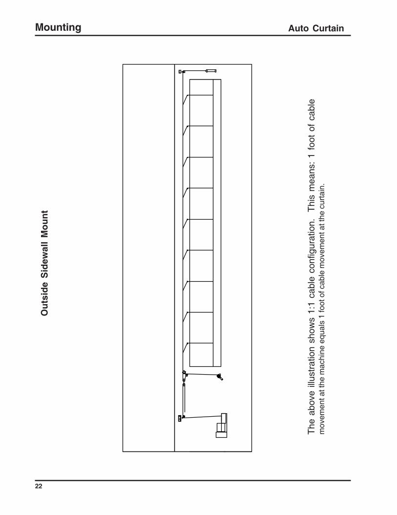
Ou
tsid
e S
idew
all
Mo
un
t
The
abo
ve i
llust
ratio
n sh
ows
1:1
cabl
e co
nfig
urat
ion.
T
his
mea
ns:
1 fo
ot o
f ca
ble
mov
emen
t at t
he m
achi
ne e
qual
s 1
foot
of c
able
mov
emen
t at t
he c
urta
in.
Mounting
Auto Curtain
23
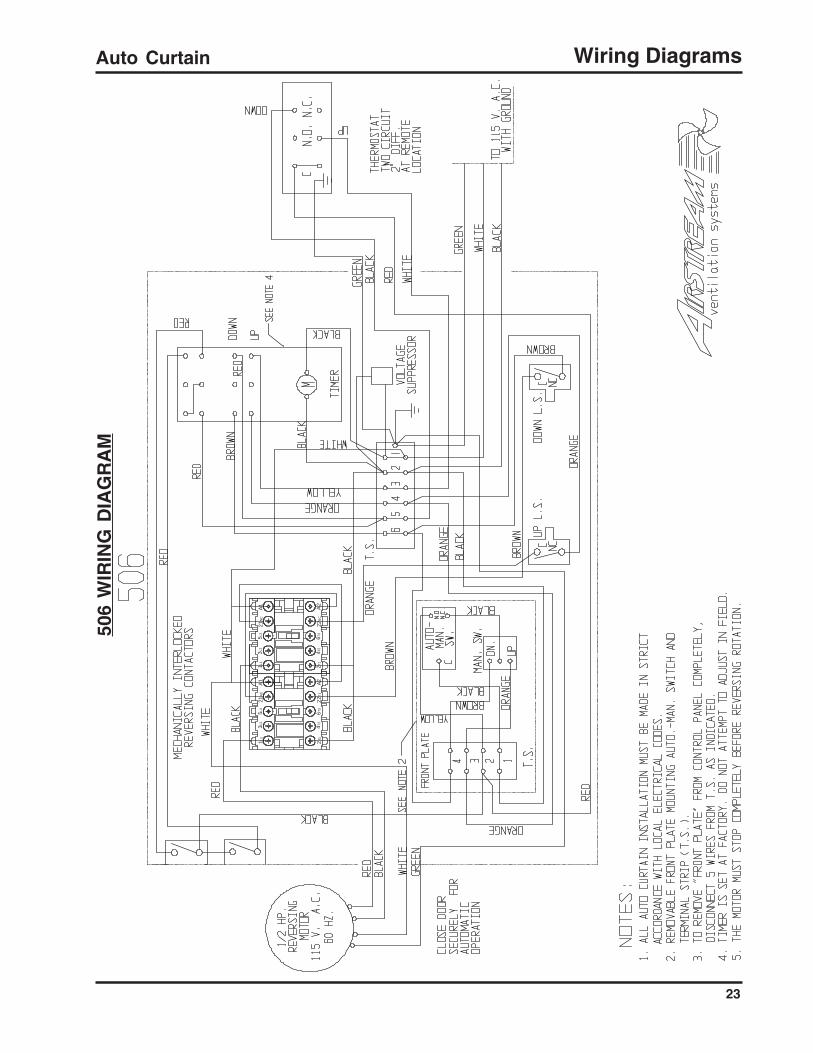
506
WIR
ING
DIA
GR
AM
Wiring Diagrams
1L1
3L2
5L3
21NC
A11 L
13L
25L
321
NCA1
2T1
4T2
6T3
22T1
A22 T
14T
26T
322
NC
A2
Auto Curtain
24
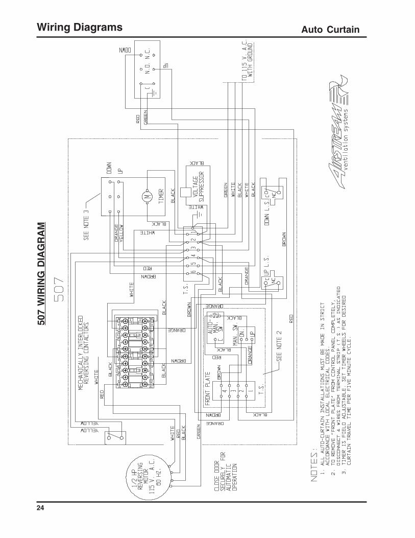
507
WIR
ING
DIA
GR
AM
Wiring Diagrams
1L1
3L2
5L3
21NC
A11 L
13L
25L
321
NCA1
2 T1
4T2
6T3
22T1
A22 T
14T
26T
322
NCA2

Auto Curtain
25
511
WIR
ING
DIA
GR
AM
Wiring Diagrams
1L1
3L2
5L3
21N
CA
11 L
13L
25L
321
NC
A1
2 T1
4T2
6T3
22T
1A2
2T1
4T2
6T3
22N
CA
2

Auto Curtain
26
Setting the AC1572Limit Switch Kit
CONTROL BOX
LIMIT SWITCHESFig. 8
NOTE: IF ANY ADJUSTMENTS ARE MADE TO KEEPTHE CURTAINS FROM CLOSING OR OPENING COM-PLETELY, ONLY MOVE THE LIMIT SWITCHES NEVERTHE WELD NUT STOP.
43
2
1
After the AUTO-CURTAIN isproperly mounted on the building,and all electrical connections arecompleted the limit switches canbe set. First, raise the curtain upslightly with the manual switchuntil both cables on the grooveddrum have tension on them. Thedrum should have 2 -3 wraps ofcable on each end before load isapplied. At this point, stop themachine and set the lower limitswitch by loosening the wingnuts (2) and sliding the rightswitch on the t-bar (3) to the leftuntil it makes contact with theactuator (4) and depresses thelimit switch. Check to see if theswitch is vertical and retightenthe wing nuts. Next, move theweld nut stop (1) up against theback of the switch and tightenthe two screws on the stop.Now that the lower limit switch isset, run the curtain to the top.As the bottom of the seam forthe reinforcing rod just clears thetop of the opening turn theAUTO-CURTAIN off.NOTE: When setting the upperlimit switch, make sure thecurtain if not pulled tight pastthe top of the opening. cur-tains that are pulled tightincrease the load on themachine.To set the upper limit switch(switch to the left of the actua-tor), slide the switch to the rightuntil the switch is depressed.While the switch is depressed,tighten the wing nuts to keep theswitch in place. Lastly, movethe weld nut stop against theswitch and retighten.
Setting Limit Switch

Auto Curtain
27
Brown
Orange
Instructions forReverse Operation
of the Machine
6 5 4 3 2 1
For curtains or doors at-tached at the top which drawor pull cables to open win-dows or curtains from thebottom up, it is necessary tochange the internal wiring ofthe Auto-Curtain to put thetimers and thermostat inproper sequence.
To achieve this:
1) Unplug the Auto-Curtainfrom the electrical outlet.
2) Open the front door andremove the front plate.
3) On the six-pole terminalblock mounted on center ofthe control box, switch thetwo brown wires on thebottom side of the terminal#6 with the two orange wireson the bottom side of terminal#4.
4) Replace the front plate.
5) Reconnect plug to electri-cal outlet.
Fig. 9
Reverse OperationIinstructions
Reverse Operation Instructions

Auto Curtain
28
The timer is located in the top righthand corner of the Auto-CurtainModel 507. It is a two circuit, 5minute cycle timer with separateadjustable cams for customizing theopening and closing (run/pausetimes) of the Auto-Curtain. The twomovable tabs on each cam deter-mine the "turn on" and "turn off"points for that circuit. The sum ofthe run time plus the pause time foreach circuit will always equal 5minutes. Each cam has a total of120 serrations (notches). Eachnotch represents 2.5 seconds of the5 minutes. The smallest amount oftime, which can be set by having thetabs on the same cam touch eachother, is 12.5 seconds (5 notches).
At the bottom of this page and thenext page are diagrams on how toset the timer. They explain how toset the (run/pause times) of both theopen and close circuits. The threecircles on this page represent onecam with different (run/pause time)settings. This diagram can be usedto set the open cam or the closecam. The same procedure is usedfor both cams. The next pageexplains in more detail how the upperand lower tabs of one cam determineif the time is run or pause.
Instructions for Setting FiveMinute Adjustable Timer on
the 507 Machine
Diagram #1
NOTE: The Next Page Explains Which Will be Run or Pause
2.) 90° Apart = 1 Min. 15 Sec. Run or Pause, 3 Min. & 45 Sec. Run or Pause
4.) Any Combination of (Run/Pause) Times Within Five Minutes
Setting the Run and Pause Times on the Open or Close Cams
Movable Tabs
Fig. 10
MOV (Volt Suppressor)# 1630
AC1737 TIMER
Open Cam
Close Cam
3.)
Run orPause
Run orPause
2.) Run orPause
Run orPause
Run orPause
1.)
Run orPause
45° Apart = 37.5 Sec. Run or Pause, 4 Min. & 22.5 Sec. Run or Pause1.)
180° Apart = 2 Min. & 30 Sec. Run or Pause, 2 Min. & 30 Sec. Run or Pause3.)
Setting Timers

Auto Curtain
29
Pause
Run
Upper Tab
Lower Tab
Upper Tab
Lower Tab
Pause
As discussed on the previ-ous page the amount ofdegrees between the upperand lower tabs on one camdetermines the amount of runtime and pause time for thatcircuit. However, whensetting the timer it is impor-tant to first determine whichtab starts the run time andwhich tab starts the pausetime. (Fig. 6) shows typicalcams with tabs. Note thelocation of the raised actua-tor on each tab. The tab withthe actuator on the bottomhalf of the cam starts the runtime. The tab with the actua-tor on the top half of the camstarts the pause time. Thecam turns CCW whenviewed from the top. To setthe timer determine theamount of run time desiredand set the tabs so the "startrun" tab (actuator on bottomhalf of cam) reaches theswitching mechanism first.Use diagram 1 to determinethe approximate distance tothe "start/pause" tab fortypical run times. As statedbefore, each notch equals2.5 seconds. It is recom-mended that the open andclose run times be offset toprevent both circuits frombeing enabled at the sametime.
Run3' 45"
1' 15"
3' 45"
1' 15"
N.C. Limit Switch
90°
90°
Instructions for SettingFive Minute Adjustable
Timer on the 507 Machine
In this setting the upper tab on the opencam (counter clockwise rotation) willmake contact with the limit switch firstso the pause time will be 1 min. & 15sec. until the lower tab on the samecam trips the limit switch and the runtime starts for 3 min. & 45 sec.
In this setting the lower tab on the opencam (counter clockwise rotation) willmake contact with the limit switch firstso the run time will be 1 min. & 15 sec.until the upper tab on the same camtrips the limit switch and the pausetime starts for 3 min. & 45 sec.
Open Cam,Upper Tab (pause)
Close Cam,Upper Tab (pause)
Close Cam,Lower Tab (run)
Fig. 11
Lower Tab = Run Time
Upper Tab = Pause Time
Counter Clockwise Rotation
N.C. Limit Switch
Top View of Open CamDiagram #2
Open Cam,Lower Tab (run)
Setting Timers

Auto Curtain
30
ITEM # DESCRIPTION / PART NUMBER (IN BOLD)27 Set Screw, 1/4"-20 x 1/2" type B / S-274228 Limit Switch Kit / AC157229 Limit Switch Actuator / 112630 Screw, 10-32 x 3/8" / S-897531 Screw, #6-32 x 5/8" / 865832 Weld Nut, #10-32 with 1" centers / 1531A33 Weld Nut, #6-32 with 1" centers / S-714834 T-bar / 152235 Cap plug, 7/8" / 457836 Liquid Tight Connector 3/4" / FH-705337 Terminal Block, 6 pole 2 row / 176338 Eagle Signal 4-circuit timer / 173839 Mov (Voltage protection up to 600V) / 163040 Hour Timer Switch, SPST, on-off / 176141 Hinged Enclosure 12" x 12" x 4" / 151442 Reversing Relay AC / 155843 Raise-Off-Lower Switch / 177544 Manual - Auto Switch SPDT / 177645 Terminal Block 4 pole 2 row / 177346 Hex Nut, #8-32 / S-652547 Front Plate, (blank) / 177948 Front Plate, (wired) / 177749 Screw, #8-32 x 1/4" / 882150 Drum Guard - Cover / AC152051 Sprocket Base / 1100S52 Sprocket Shaft / 1111B53 Sprocket, 24 teeth / 184754 Actuator nut / S-1102
ITEM # DESCRIPTION / PART NUMBER (IN BOLD)
1 Belt / Motor guard / 1462A2 V-belt 26" / 13513 Sheave, 4.95" dia. x 5/8" bore / 14234 Bolt, 5/16"-18 x 3" / S-70865 Flat washer, 3/8" x 1 1/2" x 1/4" / 80926 Gearbox (slow) / 1333-126A Gearbox (fast) / 1333-27 Bolt, 5/16"-18 x 3/4" / S-42758 Hex nut, 5/16"-18 / S-3969 Sheave, 3.00" dia. x 1/2" bore / 141210 Motor 1/2 hp, 1phase, 60hz, 1625RPM / 143911 Lockwasher, 5/16" / S-114712 Carriage Bolt, 5/16"-18 x 3/4" / S-607613 Motor Base / 110514 Bolt, 3/8"-16 x 1" / S-45515 Hex nut, 3/8"-16 / S-45616 Shear Pin, 7/32" x 1 1/4" / 134217 Drive Shaft 3/4" threaded / 111118 Fiber Washer for Drive Shaft / 340619 Bolt, 5/16"-18 x 1" / S-114620 Pillow Block Bearing 3/4" / 129221 Piano Wire Connector, 1/4" x 1 5/8" / 134322 Aluminum Grooved Drum 1 5/8" / 112122A Aluminum Grooved Drum 2 3/4" / 112223 Bolt, 3/8"-16 x 1" / S-45524 Flat Washer, 3/8" / S-24825 Concrete Nail 1 1/2" long / 188526 Nonwelded Galvanized Base / 1100
KIT #'s DESCRIPTION / PART NUMBERSAC1572 Limit Switch kit:
(1) Limit Switch 1572, (1) Cover 1573,(1) #6-32 Weld Nut S-7148, (2) #6-32 x 1½ S-7181,(2) #6-32 Wing Nuts 8657
1777 Front Plate Wired:(1) Push Button Switch 1754, (1) Manual Switch 1776,(1) Terminal Block 4pole / 2row 1773
1382A Aircraft Cable, 1 set: 5/32, 7 x 19 (2) 16' pcs.AC1568 (1) Whisker Limit Switch 1568, (1) Cover 1573,
(1) #6-32 Weld Nut S-7148, (2) #6-32 x 2 1/2" 8682,(2) Wing Nuts 8657
506, 506SParts Breakdown
Parts Breakdown

Auto Curtain
31
506, 506SExploded View
Parts Breakdown
54

Auto Curtain
32
ITEM # DESCRIPTION / PART NUMBER (IN BOLD)24 Flat Washer, 3/8" / S-24825 Concrete Nail 1 1/2" long / 188526 Nonwelded Galvanized Base / 110027 Set Screw, 1/4"-20 x 1/2" type B / S-274228 Limit Switch Kit / AC157229 Limit Switch Actuator / 112630 Screw, 10-32 x 3/8" / S-897531 Screw, #6-32 x 5/8" / 865832 Weld Nut, #10-32 with 1" centers / 1531A33 Weld Nut, #6-32 with 1" centers / S-714834 T-bar / 152235 Cap plug, 7/8" / 457836 Liquid Tight Connector 3/4" / FH-705337 Terminal Block, 6 pole 2 row / 176338 Eagle Signal 2-circuit timer / 173739 Mov (Voltage protection up to 600V) / 163040 Hour Timer Switch, SPST, on-off / 176141 Hinged Enclosure 12" x 12" x 4" / 151442 Reversing Relay AC / 155843 Raise-Off-Lower Switch / 177544 Manual - Auto Switch SPDT / 177645 Terminal Block 4 pole 2 row / 177346 Hex Nut, #8-32 / S-652547 Front Plate, (blank) / 177948 Front Plate, (wired) / 177749 Screw, #8-32 x 1/4" / 882150 Drum Guard - Cover / AC152051 Actuator nut / S-1102
KIT #'s DESCRIPTION / PART NUMBERSAC1572 Limit Switch kit:
(1) Limit Switch 1572, (1) Cover 1573,(1) #6-32 Weld Nut S-7148, (2) #6-32 x 1½ S-7181,(2) #6-32 Wing Nuts 8657
1777 Front Plate Wired:(1) Push Button Switch 1754, (1) Manual Switch 1776,(1) Terminal Block 4pole / 2row 1773
1382A Aircraft Cable, 1 set: 5/32, 7 x 19 (2) 16' pcs.AC1568 (1) Whisker Limit Switch 1568, (1) Cover 1573,
(1) #6-32 Weld Nut S-7148, (2) #6-32 x 2 1/2" 8682,(2) Wing Nuts 8657
507, 507SParts Breakdown
ITEM # DESCRIPTION / PART NUMBER (IN BOLD)
1 Belt / Motor guard / 1462A2 V-belt 26" / 13513 Sheave, 4.95" dia. x 5/8" bore / 14234 Bolt, 5/16"-18 x 3" / S-70865 Flat washer, 3/8" x 1 1/2" x 1/4" / 80926 Gearbox (slow) / 1333-126A Gearbox (fast) / 1333-27 Bolt, 5/16"-18 x 3/4" / S-42758 Hex nut, 5/16"-18 / S-3969 Sheave, 3.00" dia. x 1/2" bore / 141210 Motor 1/2 hp, 1phase, 60hz, 1625RPM / 143911 Lockwasher, 5/16" / S-114712 Carriage Bolt, 5/16"-18 x 3/4" / S-607613 Motor Base / 110514 Bolt, 3/8"-16 x 1" / S-45515 Hex nut, 3/8"-16 / S-45616 Shear Pin, 7/32" x 1 1/4" / 134217 Drive Shaft 3/4" threaded / 111118 Fiber Washer for Drive Shaft / 340619 Bolt, 5/16"-18 x 1" / S-114620 Pillow Block Bearing 3/4" / 129221 Piano Wire Connector, 1/4" x 1 5/8" / 134322 Aluminum Grooved Drum 1 5/8" / 112122A Aluminum Grooved Drum 2 3/4" / 112223 Bolt, 3/8"-16 x 1" / S-455
Parts Breakdown

Auto Curtain
33
507, 507SExploded View
Parts Breakdown
51

Auto Curtain
34
ITEM # DESCRIPTION / PART NUMBER (IN BOLD)26 Nonwelded Galvanized Base / 110027 Set Screw, 1/4"-20 x 1/2" type B / S-274228 Limit Switch Kit / AC157229 Limit Switch Actuator / 112630 Screw, 10-32 x 3/8" / S-897531 Screw, #6-32 x 5/8" / 865832 Weld Nut, #10-32 with 1" centers / 1531A33 Weld Nut, #6-32 with 1" centers / S-714834 T-bar / 152235 Cap plug, 7/8" / 457836 Liquid Tight Connector 3/4" / FH-705337 Terminal Block, 6 pole 2 row / 176338 Hour Timer Switch, SPST, on-off / 176139 Hinged Enclosure 12" x 12" x 4" / 151440 Reversing Relay AC / 155841 Raise-Off-Lower Switch / 177542 Manual - Auto Switch SPDT / 177643 Terminal Block 4 pole 2 row / 177344 Hex Nut, #8-32 / S-652545 Front Plate, (blank) / 177946 Front Plate, (wired) / 177747 Screw, #8-32 x 1/4" / 882148 Drum Guard - Cover / AC152049 Sprocket Base / 1100S50 Sprocket Shaft / 1111B51 Sprocket, 24 teeth / 184752 Actuator nut / S-1102
ITEM # DESCRIPTION / PART NUMBER (IN BOLD)
1 Belt / Motor guard / 1462A2 V-belt 26" / 13513 Sheave, 4.95" dia. x 5/8" bore / 14234 Bolt, 5/16"-18 x 3" / S-70865 Flat washer, 3/8" x 1 1/2" x 1/4" / 80926 Gearbox (slow) / 1333-126A Gearbox (fast) / 1333-27 Bolt, 5/16"-18 x 3/4" / S-42758 Hex nut, 5/16"-18 / S-3969 Sheave, 3.00" dia. x 1/2" bore / 141210 Motor 1/2 hp, 1phase, 60hz, 1625RPM / 143911 Lockwasher, 5/16" / S-114712 Carriage Bolt, 5/16"-18 x 3/4" / S-607613 Motor Base / 110514 Bolt, 3/8"-16 x 1" / S-45515 Hex nut, 3/8"-16 / S-45616 Shear Pin, 7/32" x 1 1/4" / 134217 Drive Shaft 3/4" threaded / 111118 Fiber Washer for Drive Shaft / 340619 Bolt, 5/16"-18 x 1" / S-114620 Pillow Block Bearing 3/4" / 129221 Piano Wire Connector, 1/4" x 1 5/8" / 134322 Aluminum Grooved Drum 1 5/8" / 112122A Aluminum Grooved Drum 2 3/4" / 112223 Bolt, 3/8"-16 x 1" / S-45524 Flat Washer, 3/8" / S-24825 Concrete Nail 1 1/2" long / 1885
KIT #'s DESCRIPTION / PART NUMBERSAC1572 Limit Switch kit:
(1) Limit Switch 1572, (1) Cover 1573,(1) #6-32 Weld Nut S-7148, (2) #6-32 x 1½ S-7181,(2) #6-32 Wing Nuts 8657
1777 Front Plate Wired:(1) Push Button Switch 1754, (1) Manual Switch 1776,(1) Terminal Block 4pole / 2row 1773
1382A Aircraft Cable, 1 set: 5/32, 7 x 19 (2) 16' pcs.AC1568 (1) Whisker Limit Switch 1568, (1) Cover 1573,
(1) #6-32 Weld Nut S-7148, (2) #6-32 x 2 1/2" 8682,(2) Wing Nuts 8657
511, 511SParts Breakdown
Parts Breakdown

Auto Curtain
35
511, 511SExploded View
Parts Breakdown
52

Auto Curtain
36
GEARBOX EXPLODED VIEW
Front View Cover Assembly
Side View
Out Put Gear Assembly
Parts Breakdown
Auto Curtain
37
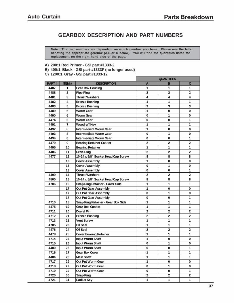
GEARBOX DESCRIPTION AND PART NUMBERS
Parts Breakdown
Note: The part numbers are dependant on which gearbox you have. Please use the letterdenoting the appropriate gearbox (A,B,or C below). You will find the quantities listed forreplacement on the right hand side of the page.
A) 200:1 Red Primer - GSI part #1333-2B) 400:1 Black - GSI part #1333F (no longer used)C) 1200:1 Gray - GSI part #1333-12
QUANTITIESPART # ITEM # DESCRIPTION A B C4487 1 Gear Box Housing 1 1 14488 2 Pipe Plug 2 2 24481 3 Thrust Washers 4 4 44482 4 Bronze Bushing 1 1 14483 5 Bronze Bushing 3 3 34489 6 Worm Gear 1 0 04490 6 Worm Gear 0 1 04474 6 Worm Gear 0 0 14491 7 Woodruff Key 1 1 14492 8 Intermediate Worm Gear 1 0 04493 8 Intermediate Worm Gear 0 1 04494 8 Intermediate Worm Gear 0 0 14479 9 Bearing Retainer Gasket 2 2 24495 10 Bearing Retainer 1 1 14486 11 Drive Plug 2 2 24477 12 10-24 x 5/8" Socket Head Cap Screw 8 8 8
13 Cover Assembly 1 0 013 Cover Assembly 0 1 013 Cover Assembly 0 0 1
4499 14 Thrust Washers 2 2 24500 15 10-24 x 5/8" Socket Head Cap Screw 8 8 84706 16 Snap Ring Retainer - Cover Side 1 1 1
17 Out Put Gear Assembly 1 0 017 Out Put Gear Assembly 0 1 017 Out Put Gear Assembly 0 0 1
4710 18 Snap Ring Retainer - Gear Box Side 1 1 14475 19 Gear Box Gasket 1 1 14711 20 Dowel Pin 2 2 24712 21 Bronze Bushing 2 2 24713 22 Vent Screw 1 1 14785 23 Oil Seal 1 1 14476 24 Oil Seal 2 2 24478 25 Cover Bearing Retainer 1 1 14714 26 Input Worm Shaft 1 0 04715 26 Input Worm Shaft 0 1 04480 26 Input Worm Shaft 0 0 14716 27 Gear Box Cover 1 1 14484 28 Main Shaft 1 1 14717 29 Out Put Worm Gear 1 0 04718 29 Out Put Worm Gear 0 1 04719 29 Out Put Worm Gear 0 0 14720 30 Snap Ring 2 2 24721 31 Radius Key 1 1 1
Auto Curtain
38
QTY.
1
4
4
1
1
1
4
2
2
1
2
1
1
50205622441121111
PART #
1820
S-248
S-456
1835
1902AA
1821
S-456
1835
1902AA
1822
S-456
1835
1902AA
S-248S-456S-7203S-7247S-7373S-724881708195
0709739919261780178117851782
B
DESCRIPTION
Bracket Outside Corner
3/8" Wrought Iron Washer
3/8" - 16 Hex Nut
U - Bolt 1" Center
3" CI Pulley w/Needle Bearing
Bracket - 3" x 3" x 9"
3/8" - 16 Hex Nut
U - Bolt 1" Center
3" CI Pulley w/Needle Bearing
Bracket - 3" x 3" x 3"
3/8" - 16 Hex Nut
U - Bolt 1" Center
3" CI Pulley w/Needle Bearing
3/8" Wrought Iron Washer3/8" - 16 Hex Nut3/8" - 16 x 2" Bolt3/8" - 16 x 3" Bolt3/8" - 16 x 5" Bolt3/8" - 16 x 6" Bolt3/8" - 16 x 7" Bolt3/8" x 12" Full Threaded Rod3/16" Cable Clamp1/4" Grab HookHandy Box CoverDuplex Receptacle 115V w/Grd.Handy Box , Surface Nail On1/2" Romex Connector
9 10
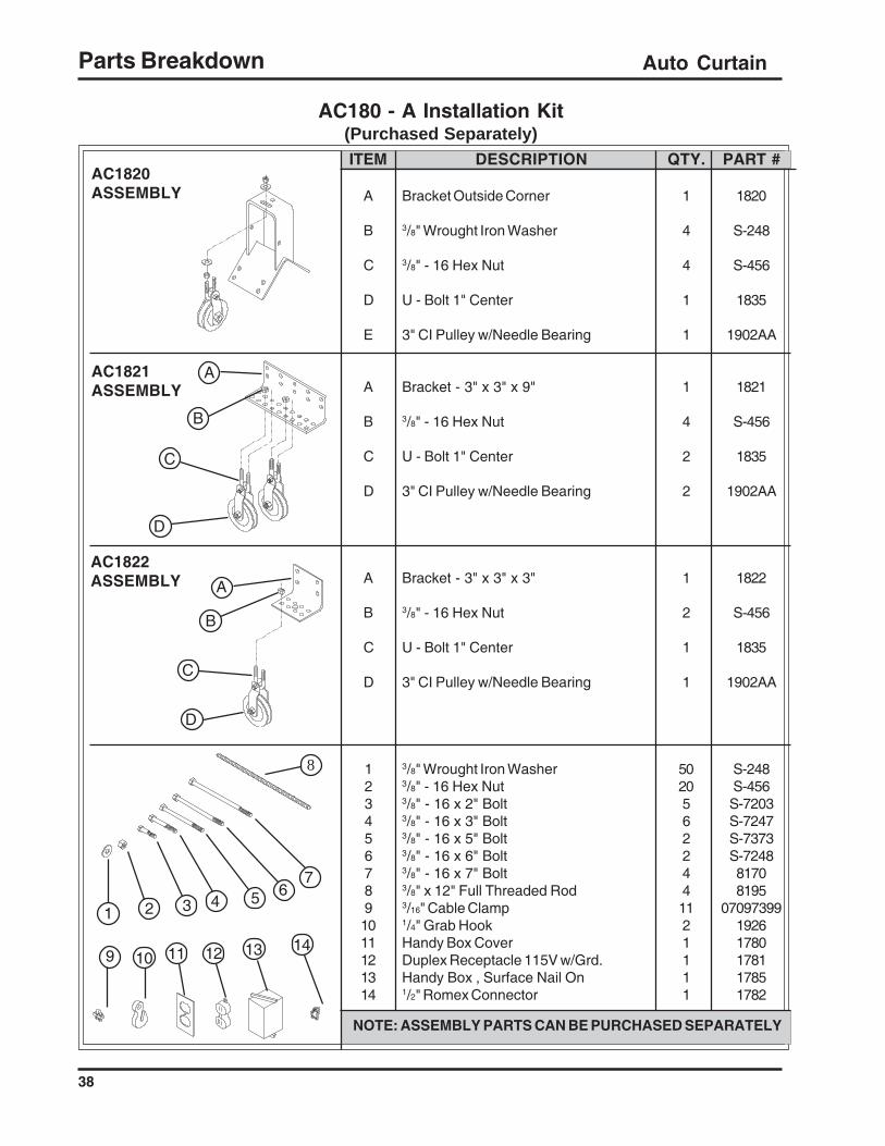
NOTE: ASSEMBLY PARTS CAN BE PURCHASED SEPARATELY
ITEM
A
B
C
D
E
A
B
C
D
A
B
C
D
1234567891011121314
8
A
B
D
D
AC1822ASSEMBLY
AC1821ASSEMBLY
AC1820ASSEMBLY
5321
76
C
C
A
4
11 12 13 14
AC180 - A Installation Kit(Purchased Separately)
Parts Breakdown

Auto Curtain
39
QTY.
1
4
2
2
5020332224821111
PART #
1821
S-456
1835
1902AA
S-248S-456S-7203S-7247S-7373S-724881708195
0709739919261780178117851782
ITEM
A
B
C
D
1234567891011121314
8
3 4 5
NOTE: ASSEMBLY PARTS CAN BE PURCHASED SEPARATELY
9
1
D
A
6
13 1411
AC1821ASSEMBLY
DESCRIPTION
Bracket - 3" x 3" x 9"
3/8" - 16 Hex Nut
U - Bolt 1" Center
3" CI Pulley w/Needle Bearing
3/8" Wrought Iron Washer3/8" - 16 Hex Nut3/8" - 16 x 2" Bolt3/8" - 16 x 3" Bolt3/8" - 16 x 5" Bolt3/8" - 16 x 6" Bolt3/8" - 16 x 7" Bolt3/8" x 12" Full Threaded Rod3/16" Cable Clamp1/4" Grab HookHandy Box CoverDuplex Receptacle 115V w/Grd.Handy Box , Surface Nail On1/2" Romex Connector
B
C
7
2
10 12
AC180 - B Installation Kit
Parts Breakdown
(Purchased Separately)

Auto Curtain
40
QTY.
1
4
2
2
2
2
2
1
2
1
1
1
1
1
1
50206224422241111
A
DESCRIPTION
Bracket - 3" x 3" x 9"
3/8" - 16 Hex Nut
U - Bolt 1" Center
Pulley, 3" w/ Shackle and Ndle.Bearing
Bolt, 5/8 x 1
1/2" Wrought Iron Washer
Pulley, 3" with Needle Bearing
Double Roller Bracket
Nut, 1/2"- 13 Deformed Lock-nut
Bolt, 5/8 x 1
1/2" Wrought Iron Washer
Pulley, 3" with Needle Bearing
Single Roller Bracket
Nut, 1/2"- 13 Deformed Lock-nut
Cable Bracket
3/8" Wrought Iron Washer3/8" - 16 Hex Nut3/8" - 16 x 3" Bolt3/8" - 16 x 5" Bolt3/8" - 16 x 6" Bolt3/8" - 16 x 7" Bolt3/8" x 12" Full Threaded RodJ - Hook 3/8" x 4"3/16" Cable Clamp1/4" Grab HookHandy Box CoverDuplex Receptacle 115V w/Grd.Handy Box , Surface Nail On1/2" Romex Connector
9 10 12 13
NOTE: ASSEMBLY PARTS CAN BE PURCHASED SEPARATELY
ITEM
A
B
C
D
A
B
C
D
E
A
B
C
D
E
F
1234567891011121314
AC1824AASSEMBLY
AC1824ASSEMBLY
AC1821ASSEMBLY
52
A
D
A
F
E
B
B
C
E
1
PART #
1821
S-456
1835
1902AA
50-0091
CH-1043
50-0089
1824
S-6493
50-0091
CH-1043
50-0089
1824
S-6493
50-0022
S-248S-456S-7247S-7373S-7248817081951928
0709739919261780178117851782
B
C
C
8
436
7
1411
AC180-C Installation Kit
F Cable Bracket 2 50-0022
DF
D
Parts Breakdown
(Purchased Separately)

Auto Curtain
41
QTY.
1
4
2
2
2
2
2
2
2
1
1
1
2
50206224422241111
PART #
1821
S-456
1835
1902AA
50-0091
CH-1043
50-0089
1824A
S-6493
1902AA
1835
1823
S-456
S-248S-456S-7247S-7373S-7248817081951928
0709739919261780178117851782
DESCRIPTION
Bracket - 3" x 3" x 9"
3/8" - 16 Hex Nut
U - Bolt 1" Center
Pulley, 3" w/ Shackle and Ndle.Bearing
Bolt, 5/8 x 1
1/2" Wrought Iron Washer
Pulley, 3" with Needle Bearing
Single Roller Bracket
Nut, 1/2"- 13 Deformed Lock-nut
Pulley, 3" w/ Shackle and Ndle.Bearing
U - Bolt 1" Center
Bracket Through Wall
3/8" - 16 Hex Nut
3/8" Wrought Iron Washer3/8" - 16 Hex Nut3/8" - 16 x 3" Bolt3/8" - 16 x 5" Bolt3/8" - 16 x 6" Bolt3/8" - 16 x 7" Bolt3/8" x 12" Full Threaded RodJ - Hook 3/8" x 4"3/16" Cable Clamp1/4" Grab HookHandy Box CoverDuplex Receptacle 115V w/Grd.Handy Box , Surface Nail On1/2" Romex Connector
ITEM
A
B
C
D
A
B
C
D
E
A
B
C
D
1234567891011121314
AC1823ASSEMBLY
AC1824AASSEMBLY
AC1821ASSEMBLY
NOTE: ASSEMBLY PARTS CAN BE PURCHASED SEPARATELY
9 10 12
5321
A
D
AD
B
C
E
A
B
C
B
C
D
46
7
8
11 13 14
AC180-T Installation Kit(Purchased Separately)
F Cable Bracket 2 50-0022
Parts Breakdown

Auto Curtain
42
Auto-Curtain Troubleshooting GuideSection One
To use this guide: locate the numbered complaint / problem in Section One, then turn to SectionTwo (pages 26-27) and find the corresponding number. Section Two gives a more detailed instruc-tion of how to correct the problem.
Problems:
I. The Auto-Curtain motor will not run in either manual or automatic modes, and makes no soundwhen the "manual switch" is moved to the "raise" and "lower" position.
Possible Causes:
A. No electrical power to the Auto-Curtain (1)B. Bad limit switch (2)C. Bad reversing contactor (3)D. Bad door interlock-push switch (4)
If the limit switch actuator is against either the upper or lower limit switch, move the limit switchwhich the actuator is against away from the actuator and then see if the Auto-Curtain will run bypushing the manual switch in the direction of the limit switch that you moved back. See Number IIIbelow if this is the case.
If the Auto-Curtain still makes no sound and is not cut off in either direction by the limit switch, youhave:
A. No power to the Auto-Curtain (1)B. Bad interlock-push switch (4)
II. The Auto-Curtain motor will not run at all, and it is not against either limit switch. However,when the manual switch is pushed to "raise" and "lower" a crisp clicking or thumping sound is heardyou have:
A. Bad motor (5)
III. The Auto-Curtain motor will run in only one direction manually.
A. Bad limit switch (2)B. Bad reversing relay coil (one side) (3)C. Bad contact points on relay (3)
IV. The Auto-Curtain will run in both directions, but the shaft or grooved drum does not turn.
A. Loose pulley or belt (6)B. Sheared pin (7)C. Bad gear case (8)D. Broken Shaft (9)
Troubleshooting

Auto Curtain
43
Auto-Curtain Trouble Shooting GuideSection One
V. The Auto-Curtain motor will run up and down in "manual", but does not run automatically up ordown.
A. Bad timer or timer motor (506,507) (10)B. Bad thermostat (1)C. Bad door interlock-push switch (4)
VI. The Auto-Curtain continuously runs up and down.
A. Bad Thermostat (11)B. Thermostat lead pinched by stapleC. Bad Timer Switch
VII. The Auto-Curtain motor buzzes, but does not run.
A. Bad motor (5)B. Bad reversing contactor (3)C. Both of these (3) and (5)
VIII. Building gets too hot or cold before curtains or doors open or close.
A. Thermostat is too near to a source of heat or cold location.B. Thermostat is in a location that the sun is shining on it at certain times.C. Thermostat is out of calibration
IX. Limit switch(s) broken.
A. Sheared pin is allowing the shaft to overspin, causing the limit switches to break (7)B. Motor is failing to fall back into start-winding (5)C. Reversing contactor is sticking (3)D. The wingnuts which hold the limit switches on the t-bar are over tightened.
Troubleshooting
Auto-Curtain Trouble Shooting GuideSection Two
(1) Electrical power to Auto-Curtain - Place test light leads on terminal block poles #1 and #2 tocheck for power. If no power, check:
A. Power to outlet for plugB. All fuses or circuit breakers in line (replace or reset as required)C. Broken power cord
(2) Limit switches - break the power going to the magnetic coils of the reversing contactor in orderto stop the curtain or door at its furthest point of travel. The plunger (when pushed in) should make

Auto Curtain
44
a small clicking sound as it is depressed in and out manually. Tightening the wing nuts that hold thelimit switches on the t-bar too tightly can result in faulty operation or malfunction of the switch. Toreplace the switch: disconnect power, remove wing nuts, slide the back cover off the switch, re-move the two wires (orange and brown) and reattach them exactly the same way to the new microswitch.
(3) Reversing contactor - conditions the electric motor to run either direction as called for by thethermostat, time clock, or manual switch. Applying 115 volts of electricity across the coil(s) fromthe center point to the outside of each coil should cause a magnetic action, in turn causing thepower transfer points to close. Defective or bad coils will not react when electricity is applied. Thepower transfer points can be closed by pushing them closed by hand. If this is done when thepower is "on" it should result in the motor running. There is also the possibility that the power pointsof the relay are not making satisfactory contact, thus prohibiting the electricity to flow across them tothe electric motor. Field replacement of reversing contact coils or points is NOT recommended. If itis defective, replace the complete reversing contactor. The left side of the reversing contactor callsfor the curtains or doors to close, and the right side to open the curtains or doors.
(4) Door interlock-push switch - is a single-pole, double-throw switch, when depressed will makea small clicking sound. This switch, when depressed by hand or by closing the door, allows elec-tricity to the thermostat on the red or common wire to select the direction the curtains or doors willtravel. When the door is open and the push-button is out, the electricity goes to the "raise"-"lower"switch where manual selection of "open" or "close" is done by hand.
(5) Power motor - the Auto-Curtain is powered by a totally enclosed, ball bearing 1/2 h.p., 48-framemotor capable of operation in both directions (clockwise and counterclockwise) from an externalreversing contactor. The black and red wires are directional wires. The black and white wires orthe red to white wires should show 115 volts between them. The white wire is a neutral and thegreen is ground. If the motor is for replacement and the motor is running in the wrong direction forthe limit switches and the "raise"-"lower" switch, the direction of the motor can be reversed byswapping the red and black wires.
(6) Pulleys and Belts - there have been times when the set screws on the motor pulley or gearcase pulley have worked loose, allowing the pulley to slip on the shaft. If this occurs, realign beltand tighten set screws as tight as possible. The V- belt should not be too tight, but should run loosewith a 1/2" to 3/4" slack. The belt is a 26" size. If the belt is running excessively tight, bearingdamage could result in the motor and gear case. Worn or cracked belts should be replaced.
(7) Shear pin - in the end of the gear case below the electric motor, there is a 7/32" x 1 1/4" roll pinwhich connects the gear case to the drive shaft. At approximately 2,850 lbs. pressure this pin willshear, allowing the curtains or doors to open. When this occurs, there is usually an obstructionsomewhere in the cable system prohibiting free movement of curtains or doors and causing greatstress. You must free the cable and correct the obstruction. Inside each Auto-Curtain control box,there is an extra roll pin. Take a punch and knock out the old pin, align the holes and install the newroll pin. When the pin is sheared, you can see the outside hub of the gear case turning, but the 3/4"shaft inside will not turn. The shear pin is necessary to prevent damage to the gear case if some-thing hangs up.
Troubleshooting

Auto Curtain
45
(8) Gear case - the gear case is a double worm gear 1,200:1 or 200:1 ratio. If the pulley shaft isturning, but the hub of the gear case is not turning, you have a stripped gear or worm. This iscaused by from excessive pressure or lack of lubrication. Replace your gear case; we do notrecommend field repairs of the gear case. The gear case is removed by taking out the shear pin,loosening the two retaining nuts and sliding the gear case from the 3/4" shaft.
(9) Broken shaft - to replace a shaft, remove the gear case and the set screw from the limitswitch actuator. Next, remove the shear pin from the drum. Remove the cables and the bearingsfrom the aluminum drum. Reinstall the new shaft.
(10) Timer and timer motor - inside the Auto-Curtain on Models 506 and 507 machine on the rightis a five-minute timer powered by a small electric timer motor. When the machine is plugged in, youshould always be able to see the timer cams turning very slowly. The cams control the timingstages when opening or closing. If this timer motor is not turning when the machine is plugged in,the timer motor is defective. The timer motor may be replaced by removing two screws beside thetimer motor and disconnecting the electric leads. If there is a malfunction in the switch gear of timer,replace the complete timer unit.
(11) Thermostat - the thermostat is a two-stage heating and cooling unit in a totally enclosed nema4X enclosure with a two-degree allowance between stages. You should be able to turn the thermo-stat knob slowly and hear two small clicks in each direction. Between these clicks should be veryclose to the room temperature. The coil on the outside of the thermostat case is filled with a gas thatexpands or contracts as the temperature as the temperatures changes, thus operating the thermo-stat switches. The red wire going to the thermostat is the common wire. The white wire calls for thecurtains or doors to close, and the black wire calls for them to open. As you manually turn thethermostat knob to raise and lower the Auto-Curtain, it will not always respond immediately. It isconnected within the Auto-Curtain in series with the five-minute timer. It could respond immediatelyor wait for as long as four minutes before responding, depending on where the timer cycle happensto be. There are a number of things that can cause seemingly incorrect thermostat temperatures.Theses include: sunshine on the thermostat; cold drafts; or dust insulating the sensing coil. Dustcan completely clog up a thermostat. Regular cleaning by blowing out with compressed air isnecessary in a dusty atmosphere. For testing purposes, you can simulate an increase in roomtemperature by holding your hand on the thermostat's coil for a full minute. You can further test apossible defective thermostat or thermostat wire by disconnecting, from the Auto-Curtain and puttinga jumper wire between the red wire and the black wire to cause curtains or doors to open; likewise,a jumper wire between the red and white wires will cause the curtains or doors to close.
(12) Raise-lower hand switch - test by shorting from center to outside poles inside the inner doorpanel. This switch allows for manual operation of curtains.
Auto-Curtain Trouble Shooting GuideSection Two
Troubleshooting

Auto Curtain
46
NOTES

9101239_1_CR_rev7.DOC (revised July 2009)
Limited Warranty
The GSI Group, LLC. (“GSI”) warrants products which it manufactures to be free of defects in materials and workmanship under normal usage and conditions for a period of 12 months after sale to the original end-user or if a foreign sale, 14 months from arrival at port of discharge, whichever is earlier. The end-user’s sole remedy (and GSI’s only obligation) is to repair or replace, at GSI’s option and expense, products that in GSI’s judgment, contain a material defect in materials or workmanship. Expenses incurred by or on behalf of the end-user without prior written authorization from the GSI Warranty Group shall be the sole responsibility of the end-user.
Warranty Extensions: The Limited Warranty period is extended for the following products:
Product Warranty Period
AP Fans and Flooring
Performer Series Direct Drive Fan Motor 3 Years
All Fiberglass Housings Lifetime All Fiberglass Propellers Lifetime
Cumberland Feeding/Watering Systems
Feeder System Pan Assemblies 5 Years ** Feed Tubes (1.75" & 2.00") 10 Years * Centerless Augers 10 Years * Watering Nipples 10 Years *
Grain Systems Grain Bin Structural Design 5 Years Grain Systems Farm Fans Zimmerman
Portable & Tower Dryers 2 Years Portable & Tower Dryer Frames and Internal Infrastructure † 5 Years
GSI further warrants that the portable and tower dryer frame and basket, excluding all auger and auger drive components, shall be free from defects in materials for a period of time beginning on the twelfth (12th) month from the date of purchase and continuing until the sixtieth (60th) month from the date of purchase (extended warranty period). During the extended warranty period, GSI will replace the frame or basket components that prove to be defective under normal conditions of use without charge, excluding the labor, transportation, and/or shipping costs incurred in the performance of this extended warranty.
* Warranty prorated from list price: 0 to 3 years – no cost to end-user 3 to 5 years – end-user pays 25% 5 to 7 years – end-user pays 50% 7 to 10 years – end user pays 75% ** Warranty prorated from list price: 0 to 3 years – no cost to end-user 3 to 5 years – end-user pays 50% † Motors, burner components and moving parts not included. Portable Dryer screens included. Tower Dryer screens not included.
Conditions and Limitations: THERE ARE NO WARRANTIES THAT EXTEND BEYOND THE LIMITED WARRANTY DESCRIPTION SET FORTH ABOVE. SPECIFICALLY, GSI MAKES NO FURTHER WARRANTY OF ANY KIND, EXPRESS OR IMPLIED, INCLUDING, WITHOUT LIMITATION, WARRANTIES OF MERCHANTABILITY OR FITNESS FOR A PARTICULAR PURPOSE OR USE IN CONNECTION WITH: (i) PRODUCT MANUFACTURED OR SOLD BY GSI OR (ii) ANY ADVICE, INSTRUCTION, RECOMMENDATION OR SUGGESTION PROVIDED BY AN AGENT, REPRESENTATIVE OR EMPLOYEE OF GSI REGARDING OR RELATED TO THE CONFIGURATION, INSTALLATION, LAYOUT, SUITABILITY FOR A PARTICULAR PURPOSE, OR DESIGN OF SUCH PRODUCTS.
GSI shall not be liable for any direct, indirect, incidental or consequential damages, including, without limitation, loss of anticipated profits or benefits. The sole and exclusive remedy is set forth in the Limited Warranty, which shall not exceed the amount paid for the product purchased. This warranty is not transferable and applies only to the original end-user. GSI shall have no obligation or responsibility for any representations or warranties made by or on behalf of any dealer, agent or distributor.
GSI assumes no responsibility for claims resulting from construction defects or unauthorized modifications to products which it manufactured. Modifications to products not specifically delineated in the manual accompanying the equipment at initial sale will void the Limited Warranty.
This Limited Warranty shall not extend to products or parts which have been damaged by negligent use, misuse, alteration, accident or which have been improperly/inadequately maintained. This Limited Warranty extends solely to products manufactured by GSI.
Prior to installation, the end-user has the responsibility to comply with federal, state and local codes which apply to the location and installation of products manufactured or sold by GSI.

The GSI Group, Inc.P.O. Box 20, 1004 E. Illinois St.Assumption, Il. 62510-0020United States of America
THIS EQUIPMENT SHALL BE INSTALLED IN ACCORDANCE WITHTHE CURRENT INSTALLATION CODES AND APPLICABLE REGU-LATIONS WHICH SHOULD BE CAREFULLY FOLLOWED IN ALLCASES. AUTHORITIES HAVING JURISDICTION SHOULD BE CON-SULTED BEFORE INSTALLATIONS ARE MADE.
Phone: (217) 226- 4421Fax: (217) 226-3199e-mail: [email protected]: http://www.grainsystems.com