Author's personal copy - yu.ac.kr
12
This article appeared in a journal published by Elsevier. The attached copy is furnished to the author for internal non-commercial research and education use, including for instruction at the authors institution and sharing with colleagues. Other uses, including reproduction and distribution, or selling or licensing copies, or posting to personal, institutional or third party websites are prohibited. In most cases authors are permitted to post their version of the article (e.g. in Word or Tex form) to their personal website or institutional repository. Authors requiring further information regarding Elsevier’s archiving and manuscript policies are encouraged to visit: http://www.elsevier.com/copyright
Transcript of Author's personal copy - yu.ac.kr

This article appeared in a journal published by Elsevier. The attachedcopy is furnished to the author for internal non-commercial researchand education use, including for instruction at the authors institution
and sharing with colleagues.
Other uses, including reproduction and distribution, or selling orlicensing copies, or posting to personal, institutional or third party
websites are prohibited.
In most cases authors are permitted to post their version of thearticle (e.g. in Word or Tex form) to their personal website orinstitutional repository. Authors requiring further information
regarding Elsevier’s archiving and manuscript policies areencouraged to visit:
http://www.elsevier.com/copyright

Author's personal copy
Chemical Engineering and Processing 49 (2010) 825–835
Contents lists available at ScienceDirect
Chemical Engineering and Processing:Process Intensification
journa l homepage: www.e lsev ier .com/ locate /cep
Design and optimization of a dividing wall column for debottlenecking of theacetic acid purification process
Nguyen Van Duc Long, Seunghyun Lee, Moonyong Lee ∗
School of Chemical Engineering and Technology, Yeungnam University, Kyongsan 712-749, South Korea
a r t i c l e i n f o
Article history:Received 24 April 2010Received in revised form 16 June 2010Accepted 19 June 2010Available online 26 June 2010
Keywords:DistillationDividing wall column (DWC)DebottleneckingFully thermally coupled distillation column
a b s t r a c t
The dividing wall column (DWC) has gained increasing application in a variety of chemical processesbecause of its potentiality in energy and capital cost savings in multicomponent separations. The mainobjective in this work is investigation of its use for removing the bottleneck phenomenon within thecolumn when increasing the throughput of an existing distillation process, particularly, the acetic acid(AA) purification process. Optimal column sequence design, involving both conventional and DWC, isconsidered. The internal recycle flow distribution around the dividing wall was investigated as a primaryoptimizing variable. Several column arrangements were analyzed to show that the DWC requires lessinvestment and energy costs than conventional distillation, the Petlyuk column, or the prefractionatorarrangement.
© 2010 Elsevier B.V. All rights reserved.
1. Introduction
It is well-known that distillation plays an important role in thechemical process industries and consumes the largest amount ofenergy with an estimated 3% of the world’s energy consumption[1]. Development of a new type of column and/or performanceenhancement of existing distillation processes for improved energyefficiency have been imperative issues associated with distillation[2].
For ternary separations, either the direct or indirect sequenceswith two conventional columns are typically employed to separatethe mixture according to product specifications. Although the con-trol and operation strategy for the conventional columns is simple,it is inefficient in terms of energy due to the mixing entropy by irre-versible split [3]. Therefore, various strategies have been appliedto improve the energy efficiency of such distillation systems. Onein particular is thermal coupling, whereby the transfer of heat isachieved by a direct contact of material flow between the columns[4–6]. Many studies confirm that the fully thermally coupled distil-lation system (FTCDS) or the Petlyuk column offers a great chanceat reduced energy consumption [7–11]. In lieu of two condensersand two reboilers as the normal two column sequence, the Pet-lyuk column has only one condenser and one reboiler due to fullintegration of the prefractionator and main column, schematicallydrawn in Fig. 1a. In the Petlyuk column arrangement, reversiblesplits are possible and no part of the separation is performed twice,
∗ Corresponding author. Tel.: +82 53 810 2512; fax: +82 53 811 3262.E-mail address: [email protected] (M. Lee).
which mainly attribute superior energy efficiency for separationover other column configurations [12].
However, the Petlyuk column undergoes strong interactionsbetween the two columns because of their thermal integration,which causes some difficulties in design and operation. To solvethis problem, as well as reduce the capital cost, a vertical wallis installed in the central section of the column, dividing it intothe prefractionator and the main section, as seen in Fig. 1b. Thisarrangement is referred to as the dividing wall column (DWC),which is conceptually the same as the Petlyuk column given thethermodynamically equivalent arrangements [6], and more than90 applications in commercial scale are known [3].
When the throughput of an existing distillation columnsequence increases, entrainment flooding may create a bottleneckin the column. The goal of a retrofit design is identification andremoval of such bottlenecks [13]. Most retrofit practices in distil-lation have emphasized column internals that not only promoteseparation, but also govern the column hydraulic performance[14]. However, using better internals to debottleneck distillationcolumns is not the only design option, nor is it always the mostcost effective [13]. In some cases, this does not improve the energyefficiency of the system and could subsequently prevent a largeincrease in capacity [15]. Furthermore, in the case where the col-umn already has a high efficiency internal, the potential for capacityincreases by replacing the existing column internal with a new oneis very limited.
The key to a successful retrofit lies in maximizing utilizationof the existing equipment, while simultaneously minimizing thenew hardware so as to abbreviate capital costs. Re-arrangementof existing columns to complex column arrangements, such as the
0255-2701/$ – see front matter © 2010 Elsevier B.V. All rights reserved.doi:10.1016/j.cep.2010.06.008

Author's personal copy
826 N. Van Duc Long et al. / Chemical Engineering and Processing 49 (2010) 825–835
Fig. 1. Schematic diagram of: (a) Petlyuk column and (b) dividing wall column.
Petlyuk column and the prefractionator arrangement, has been pro-posed for retrofitting [14]. Likewise, addition of a new column,such as a post-fractionator or prefractionator, could also providea process debottlenecking option [16]. Accordingly, constructionmaterial for the new column must be considered, which is relateddirectly to investment cost and corrosion phenomenon. Whilesome modification methods have been successfully proposed toreduce investment and operating costs, it is nevertheless necessaryto consider each particular case based on realistic conditions.
The main objective of this work is to introduce how theDWC can be utilized for removing the bottleneck phenomenonas well as improving energy efficiency, particularly, in the aceticacid purification process comprising series of distillation columnswhen increasing the throughput. One of main ideas is to shift theincreased load into the subsequent columns and to have the DWCtake care the load. Various possible distillation arrangements aswell as the DWC configuration were studied and evaluated to findthe best option in a systematic manner.
The shortcut method utilizing a three conventional column con-figuration was used to find the initial DWC structure in a simplemanner. The optimal design of the DWC was considered in terms ofthe total number of trays, feed tray location, and side tray location,as well as the dividing wall section. In addition, the internal recycleflow distribution around the dividing wall was investigated as themain optimizing variable. The study was performed using AspenHYSYS V7.1. These results were then compared to the performance
Fig. 2. Simplified flow sheet illustrating the existing separation train of three con-ventional columns.
of the conventional column sequence and the Petlyuk column, aswell as the prefractionator arrangement.
1.1. Existing process configuration
Acetic acid (AA) is an important industrial commodity chemical,with many industrial uses and a world demand of nearly six milliontonnes per year [17]. The preferred industrial method for its manu-facture is carbonylation of methanol, accounting for approximately60% of the total world manufacturing capacity, whereby a mixtureof crude AA and contaminants is separated in a series of distilla-tion columns [18]. Fig. 2 illustrates the existing distillation columnsequence and current operating conditions. The existing systemhas three valve-trayed columns of 4.4, 3.0, and 3.8 m diameters,with 17, 50, and 65 trays, respectively. The production medium forthe acetic acid in the purification stage at 130–200 ◦C contains upto 16% water, 26% methyl iodize, and other components such asmethyl acetate, methanol, hydrogen iodide, formic acid (FA), andpropionic acid (PA). The role of the C-301 fractionating column isremoval of the light components and portions of water in the mix-ture, while treating both water and FA, and PA, are the purposeof the C-302 dehydration column and the C-304 refining column,respectively.
In the production of AA, the construction material hasto be considered carefully because of corrosion. Usually,nickel–molybdenum alloys (Hastelloy B and Hastelloy B-2) areemployed in this very aggressive media for production of syntheticacetic acid. However, equipment made of Hastelloy is subject toenhanced corrosion [19,20]. Electrochemical corrosion can occurin iodide-containing AA media, damaging the fractionation anddehydration columns [21]. It is thus expedient to use zirconiumalloys [20]. In this design, the fractionating C-301 and dehydra-tion C-302 are constructed of zirconium, while the refining C-304is constructed of 316SS as almost all iodide ion is removed beforeentering this column.
The feed composition, temperature, and pressure are describedin Table 1. The simulation work was performed using simu-lator Aspen HYSYS V7.1. The NRTL-HOC property method thatuses the Hayden–O’Connell equation of state as the vapor phasemodel and NRTL for the liquid phase was used for the predic-tion of the vapor–liquid equilibrium (VLE) of these simulations.Dimerization affects VLE, vapor phase properties, such as enthalpyand density, and liquid phase properties, such as enthalpy. TheHayden–O’Connell equation reliably predicts the solvation of polarcompounds and dimerization in the vapor phase that occurs withmixtures containing carboxylic acids [22]. Table 2 presents the con-ditions and product specifications for each column in the existingcolumn sequences. From the base case simulation model, it showsthat the energy consumption of three columns are 17.39, 13.05, and19.06 Gcal/h, respectively.

Author's personal copy
N. Van Duc Long et al. / Chemical Engineering and Processing 49 (2010) 825–835 827
Table 1Conditions of the feed mixture.
Feed conditions
Component Mass flow (kg/h) Mass fraction (%)
Carbon-monoxide 1105.42 0.60Hydrogen iodide 36.29 0.02Methyl iodide 48808.40 26.50Methyl acetate 3683.21 2.00Methanol 183.71 0.10Formic acid (FA) 736.64 0.40Water 30037.65 16.31Acetic acid (AA) 98778.92 53.63Propionic acid (PA) 810.58 0.44
Temperature (◦C) 166Pressure (bar) 5.50
1.2. Existing column hydraulics
Column hydraulics, as well as flooding, has to be considered.When the downcomer is small or the downcomer backup is high,downcomer flooding occurs, causing liquid accumulation in thetray above, while the rising of the vapor velocity causes entrain-ment. To determine the max flooding of a particular column, therating mode is simulated with column internal specifications suchas type of trays, column diameter, tray spacing, and number ofpasses. Table 2 lists parameters necessary to define the existinghydraulic features of the columns. All columns were designed witha load which is at near 85% of the load at the flooding point toprevent flooding in the columns.
2. Increasing daily production
In the retrofit design to increase throughput of distillation pro-cesses, existing internals are usually replaced with high capacityor high efficiency internals; the process could also be revampedby improving the utilization of existing equipment and makingrelatively minor modifications, including adjusting operating con-ditions and adding equipment [13]. In this paper, the retrofit projectpurpose is throughput increase to produce the bottleneck problem,with the following assumptions:
a. AA production must increase by 25% over the existing one.b. The existing columns are already operating with the highest per-
formance internals.c. All condensers and reboilers are fully utilized.d. The recovery of AA is kept constant.e. The operating velocity of all columns is near 85% of the flooding
velocity.
Table 2Column hydraulics, energy performance, and product specifications of the existingcolumns sequence.
C-301 C-302 C-304
Number of trays 17 50 65Tray type Valve Valve ValveColumn diameter (m) 4.4 3.0 3.8Number of flow paths 1 1 1Tray spacing (mm) 609.6 457 457Max flooding (%) 85.95 84.26 87.03
Condenser duty (Gcal/h) 49.26 25.71 20.01Reboiler duty (Gcal/h) 17.39 13.05 19.06Recovery of acetic acid (%) 65.41 80.17 88.77Purity of acetic acid (%) 82.50 98.92 99.92
FA amount in final product stream (ppm) 580 (<1000 ppm)PA amount in final product stream (ppm) 49 (<300 ppm)Production rate (ton/day) 1105
Table 3Column hydraulics, energy performance, and product specifications upon increasingthe AA daily production rate by 25%.
C-301 C-302 C-304
Number of trays 17 50 65Tray type Valve Valve ValveColumn diameter (m) 4.4 3.0 3.8Number of flow paths 1 1 1Tray spacing (mm) 609.6 457 457Max flooding (%) 86.30 85.60 103.23
Condenser duty (Gcal/h) 51.56 20.66 25.26Reboiler duty (Gcal/h) 11.30 7.60 24.39Recovery of acetic acid (%) 65.41 80.16 88.77Purity of acetic acid (%) 80.77 96.93 98.44
FA amount in final product stream (ppm) 5522 (>1000 ppm)PA amount in final product stream (ppm) 300Production rate (ton/day) 1380
f. Specification of product:- FA and water concentration must be less than 1000 ppm.- PA concentration is less than 300 ppm.
g. To evaluate the energy saving of the methods compared, the totalenergy of all columns, except C-301, was used.
With a target production at 1380 ton/day AA, the new basewas simulated using the old process configuration, whereby allcolumns (C-301, C-302, C-304) were utilized to obtain the product.For process simulation, all columns were adjusted for the samerecovery of AA for each column and a load which is at near 85%of the load at the flooding point. Table 3 presents the columnhydraulics, energy performance, and product specifications whenincreasing the daily production rate of AA by 25%. Unfortunately,the results show that it is impossible to use the existing columnsequence, the reason being that when increasing the throughput,the impurity amount is also concomitantly increased. ColumnsC-301 and C-302 could not operate sufficiently to remove thecontaminants. Therefore, more impurity, including FA, water, andPA, enters refining column C-304, causing not only the amountof FA in the final product stream to be 5522 ppm, significantlyhigher than the allowable impurity level in the product (must beless than 1000 ppm), but also flooding in C-304 as the column isbottlenecked. The retrofitting opportunity for replacing internalswith new ones is excluded in this study since the columns arealready operated with the highest performance internals.
Thus, to obtain requirements of product in terms of produc-tivity, recovery, and purity, several potential configurations wereproposed for energy saving and process debottlenecking, as shownin Fig. 3. These include re-traying the existing column, adding a newcolumn, re-arranging the existing column into a complex arrange-ment, retrofitting the existing column to a DWC, and using a newDWC.
Adding a new pre-treatment column upstream of C-302 couldbe used for debottlenecking. The construction material for pre-treatment must be considered because electrochemical corrosioncan occur in iodide-containing AA media. This is economicallyunfeasible, however, given the costly metals required, particularlyzirconium. Hence, adding a new column downstream is preferred.
The combination of two columns to produce a complex arrange-ment often proves beneficial. Since there is no remixing in C-301,integration of C-301 and C-302 is not a good option, although theyare of the same construction material. The other option is com-bination of C-302 and C-304. However, another problem occursrelated to the corrosion phenomenon. The construction materialof the column, combined with C-302 to obtain the required prod-uct performance, must have a corrosion resistance aptitude. Thus, itis unwise to combine C-302 and C-304 to create either the Petlyuk

Author's personal copy
828 N. Van Duc Long et al. / Chemical Engineering and Processing 49 (2010) 825–835
Fig. 3. The nine separation trains explored for column debottlenecking. All the gray columns are new columns or existing columns retrofitted to a DWC.
or prefractionator arrangement. Instead, the new column, the samematerial as C-302, is added. However, this option may require sig-nificant investment costs. In this study, the complex systems wereinvestigated to compare with other cases.
Fortunately, because the iodide ion is almost completelyremoved by the C-301 and C-302 columns, the existing C-304 ornew additional columns can be constructed with stainless steel316SS, except for the new additional column, which is combinedwith C-302 to produce the complex arrangement.
Note that in the whole of works related to estimation of invest-ment costs, Guthrie’s modular method was applied [23]. Theinvestment cost for conventional distillation is the total cost ofthe column and the auxiliary equipment, such as reboiler and con-denser, while for the DWC it entails the additional dividing wallcost. In this study, for cost updating, the Chemical Engineering PlantCost Index of 575.4 was utilized.
The cost of energy consumption depends on the temperature.Since the temperatures on the bottom section of the columns forvarious configurations were similar enough, the analysis based onthe energy consumption still leads to acceptable comparison ofthese configurations and can be considered as a good index forannual cost.
3. Proposed modifications
3.1. Conventional column sequence
3.1.1. Case 1.1 – adding two new columnsTo obtain the required product performance, the conventional
column sequence is first investigated, thoroughly utilizing the old
system. In order to increase throughput, the max flooding of eachcolumn, as well as acetic acid recovery, needs to be kept con-stant. Fig. 4a shows the separation train involving five conventionalcolumns that is applied to purify AA from contaminants when C-304 is bottlenecked. Note that the purpose of column C-306 is toremove FA and water. Adding two new conventional distillationcolumns can be utilized for process debottlenecking; however, it isnot preferred for saving on energy and investment costs. Neverthe-less, this case is considered as the base case to evaluate retrofittingefficiency when exploitation of C-304 is continued.
3.1.2. Case 1.2 – replacing C-304 and adding one new columnThe retrofit of an existing plant is usually carried out after
the starting time for some of the objectives, such as processdebottlenecking, in order to increase capacity or energy savings.Replacement of the existing column can be a good option when thelifetime of the column is over or little time remains on it. Hence,for obtaining the required product performance, another conven-tional column sequence is investigated, one which replaces C-304with a new column possessing a larger diameter and adds onemore column C-306. Fig. 4b shows the separation train, involvingfour conventional columns, employed to purify acetic acid fromcontaminants when C-304 is bottlenecked. All new columns werebased upon the optimal design. This case is considered a base casefor comparison with others when C-304 is replaced with a newcolumn. Based upon the simulation, the new column (diameter of4.3 m) is used to replace C-304, while another column C-306 (diam-eter of 2.9 m) is required to remove the water and FA. The energyconsumption of the two new columns is 24.45 and 13.97 Gcal/h,

Author's personal copy
N. Van Duc Long et al. / Chemical Engineering and Processing 49 (2010) 825–835 829
Fig. 4. Simplified flow sheet illustrating the separation train showing: (a) five conventional columns, including one new column added in parallel with C-304 and anotheradded in series and (b) four conventional columns, including a new C-304 and one new column added in series.
respectively. This option can be utilized for process debottleneck-ing; however, it is not preferred for saving on energy.
3.2. Re-arranging the existing column into a complexarrangement
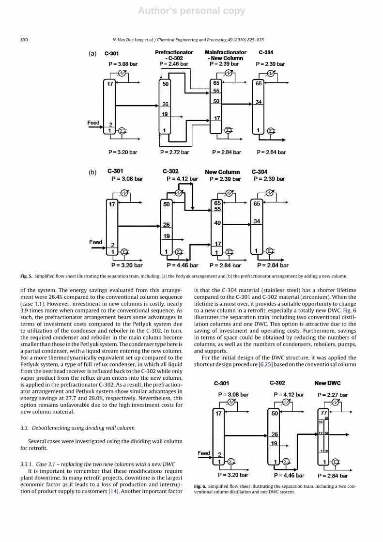
3.2.1. Case 2.1 – re-arranging the existing column into a Petlyukcolumn arrangement
Some authors [14,24] have proposed the Petlyuk column con-figuration, equivalent to the dividing wall column, as a route totake advantage of the two existing columns. With this arrangement,the column with fewer trays becomes a prefractionator while theother acts as the main column. However, this can be applied whenthe two existing columns are of the same construction material.Unfortunately, those of C-302 and C-304 are different, the formerbeing made of zirconium and the latter stainless steel. Hence, anew zirconium-column was added to combine with the C-302 toproduce a Petlyuk column arrangement whose side stream entersthe C-304 to remove FA and water, as shown in Fig. 5a. Further-more, a new condenser and reboiler, constructed of zirconium,were required as they are bottlenecked. With this new configu-ration it was possible to save 28.0% on energy consumption whencompared to the conventional column sequence (case 1.1). How-
ever, even if only one new column was added, the investmentcost was almost 4.1 times higher than the conventional columnsequence case due to such expensive material. In addition, the Pet-lyuk column arrangement is not recommended in practice as itpossesses strong interactions between the two columns that cancause some difficulties in the design and operation.
3.2.2. Case 2.2 – re-arranging the existing column into aprefractionator arrangement
A prefractionator arrangement was also studied for a retrofit.By adding one new column constructed of zirconium, the pre-fractionator arrangement can be produced. This prefractionatorarrangement takes advantage of control and operation, wherebycontrol of the external flows from the reboiler and condenser ofC-302 is facile. The prefractionator configuration is advantageousto conventional distillation schemes and shows a better energyperformance [14].
The design of the prefractionator arrangement is shown inFig. 5b. Rigorous simulation based on the equilibrium-stage modelwas performed for this arrangement by adjusting the flow of AA inthe bottom stream of the C-302, as well as the feed tray location ofthe new column, to maximize use of the existing column and min-imize the size of the new column and total energy consumption
Author's personal copy
830 N. Van Duc Long et al. / Chemical Engineering and Processing 49 (2010) 825–835
Fig. 5. Simplified flow sheet illustrating the separation train, including: (a) the Petlyuk arrangement and (b) the prefractionator arrangement by adding a new column.
of the system. The energy savings evaluated from this arrange-ment were 26.4% compared to the conventional column sequence(case 1.1). However, investment in new columns is costly, nearly3.9 times more when compared to the conventional sequence. Assuch, the prefractionator arrangement bears some advantages interms of investment costs compared to the Petlyuk system dueto utilization of the condenser and reboiler in the C-302. In turn,the required condenser and reboiler in the main column becomesmaller than those in the Petlyuk system. The condenser type here isa partial condenser, with a liquid stream entering the new column.For a more thermodynamically equivalent set up compared to thePetlyuk system, a type of full reflux condenser, in which all liquidfrom the overhead receiver is refluxed back to the C-302 while onlyvapor product from the reflux drum enters into the new column,is applied in the prefractionator C-302. As a result, the prefraction-ator arrangement and Petlyuk system show similar advantages inenergy savings at 27.7 and 28.0%, respectively. Nevertheless, thisoption remains unfavorable due to the high investment costs fornew column material.
3.3. Debottlenecking using dividing wall column
Several cases were investigated using the dividing wall columnfor retrofit.
3.3.1. Case 3.1 – replacing the two new columns with a new DWCIt is important to remember that these modifications require
plant downtime. In many retrofit projects, downtime is the largesteconomic factor as it leads to a loss of production and interrup-tion of product supply to customers [14]. Another important factor
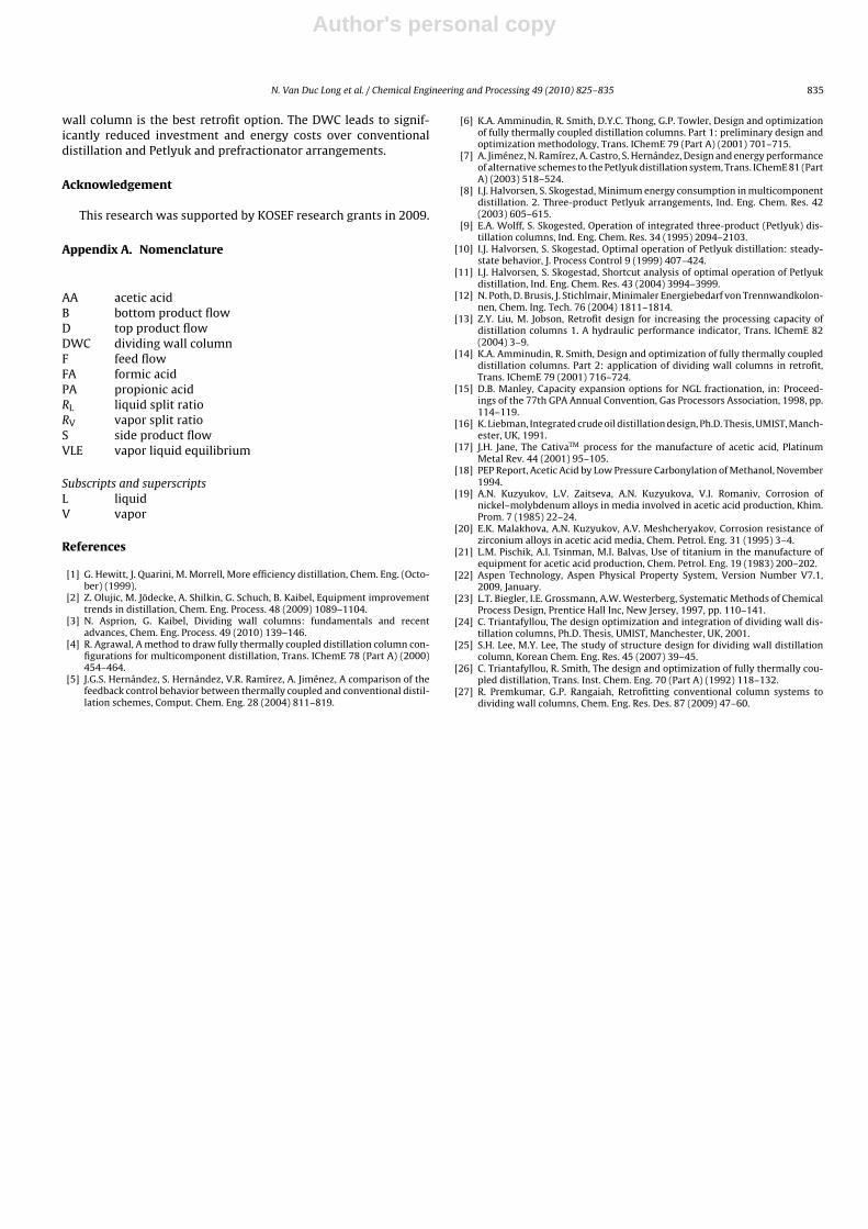
is that the C-304 material (stainless steel) has a shorter lifetimecompared to the C-301 and C-302 material (zirconium). When thelifetime is almost over, it provides a suitable opportunity to changeto a new column in a retrofit, especially a totally new DWC. Fig. 6illustrates the separation train, including two conventional distil-lation columns and one DWC. This option is attractive due to thesaving of investment and operating costs. Furthermore, savingsin terms of space could be obtained by reducing the numbers ofcolumns, as well as the numbers of condensers, reboilers, pumps,and supports.
For the initial design of the DWC structure, it was applied theshortcut design procedure [6,25] based on the conventional column
Fig. 6. Simplified flow sheet illustrating the separation train, including a two con-ventional column distillation and one DWC system.

Author's personal copy
N. Van Duc Long et al. / Chemical Engineering and Processing 49 (2010) 825–835 831
configuration shown in Fig. 7. In this conventional configuration,the first column corresponds to the prefractionator section in theDWC. The rectifying section of the second column and the strippingsection of the third column represent the top and bottom sectionsof the DWC, respectively. Both the stripping section of the secondcolumn and the rectifying section of the third column are equiva-lent to the divided wall section of the DWC. Furthermore, both thebottom stream from the second column and the top stream fromthe third column refer to the side stream of the DWC [25]. Conse-quently, the structure of the DWC can be divided into four sections:the prefractionator section for the feed mixture; the top and bot-tom sections above and below the divided wall; the divided wallsection.
As mentioned previously, the main concern of the DWC appli-cation was not only to debottleneck the column, but also save onenergy consumption and investment costs. Therefore, the designof the dividing wall column will be described in detail. After theDWC structure design procedure, the internal recycle flows to theprefractionator were optimized as shown in Fig. 8a. The circle sym-bol is the optimal point. Then, the total numbers of trays, feedtray location, side tray location, as well as the dividing wall sec-tion, were also investigated to establish an optimal DWC structure.For each chosen number of trays, feed and side tray location, anddividing wall section, the internal vapor and liquid flow to the pre-fractionator were varied to optimize energy consumption, whichbears significant influence on overall plant profitability.
Fig. 8b shows the effect of the tray number on the reboiler duty.It is clearly seen that reboiler duty rapidly decreases when the num-ber of trays increases from 71 to 75, and slightly decreases when Fig. 7. Schematic diagram of a three-column distillation system for initial design of
DWC structure.
Fig. 8. Effects of: (a) liquid and vapor flow into the prefractionator section; (b) the number of trays of the main fractionator; (c) the feed tray location; and (d) the side traylocation on the reboiler duty of the DWC.

Author's personal copy
832 N. Van Duc Long et al. / Chemical Engineering and Processing 49 (2010) 825–835
Table 4Effects of the dividing wall section on the reboiler duty of the DWC.
Dividing wall section (35, 65) (37, 67) (39, 69) (41, 71) (43, 73) (45, 75)Reboiler duty (Gcal/h) 24.28 23.91 23.91 23.93 24.45 24.68FA fraction (ppmw) 712 714 711 780 893 1149
Table 5Diameter of the DWC for a required maximum flooding.
Prefractionator Mainfractionator (middle) DWC (middle) DWC (top) DWC (bottom) DWC
Diameter (m) 2.4 3.2 4.0 4.0 4.0 4.0Max flooding (%) 83.30 82.31 85.11 84.79Position of section 40th tray–69th tray 70th tray–79th tray 1st tray–39th tray
it increases from 75 to 77. Then, the reboiler duty remains stablewhen the number of trays continues to increase. Therefore, 77 trayswere employed in the design of the DWC.
In an optimal distillation design, the composition of the feedtray was required to be close to the feed composition in order toeliminate irreversible mixing at the feed tray [26]. To examine the
effects of the feed tray on energy consumption, a number of sim-ulation runs were carried out by varying the feed tray locationfrom the 10th tray to the 22nd tray. As seen in Fig. 8c, the feedmust be fed into the 12th tray to achieve the lowest reboiler dutyand meet the required product specifications in terms of impurityconcentration.
Fig. 9. Simplified flow sheet illustrating the separation train, showing four columns, including the additional DWC: (a) parallel with C-304 and (b) in the series.

Author's personal copy
N. Van Duc Long et al. / Chemical Engineering and Processing 49 (2010) 825–835 833
Similarly, the side tray location and dividing section werealso examined to find out the optimal structure of the DWC.Fig. 8d and Table 4 show the effects of the side tray locationand dividing section, respectively. According to the simulationresults, the liquid split ratio (RL) and vapor split ratio (RV) were2.42 and 1.68, respectively. By this sequence, the FA and PA con-centrations were 711 and 300 ppm, respectively. With an energyconsumption of 23.91 Gcal/h, the DWC system saves up to 37.8%on energy consumption compared to conventional sequences(case 1.2).
The cross-sectional area of the middle section of the new DWC isthe sum of the prefractionator section area and the middle sectionarea of the main fractionator. The diameter of the middle sectioncan be calculated from the cross-sectional area of the middle sec-tion. Table 5 shows the diameter of the top, middle, and bottomsections of the DWC. Based on the results in Table 5, a length of4.0 m was chosen as the diameter of the DWC. With this, it is possi-ble to save up to 31.0% on investment costs over the conventionalcolumn sequence.
3.3.2. Case 3.2 – re-traying C-304 and adding a new DWC inparallel with C-304
Instead of adding two new columns (C-305 and C-306), anotheroption, including re-traying C-304 and adding a new DWC in par-allel with C-304, was studied. Herein, the DWC was employedprimarily to debottleneck the distillation column and fully employthe existing columns. As shown in Fig. 9a, the bottom stream of C-302 was divided into two streams. The first was pumped to C-304for purification of the acetic acid to obtain the required impuri-ties concentration. The existing C-304 is generally not optimizeand thus needs to be. The side stream location is varied to achievethe lowest reboiler duty and satisfy the fixed maximum flooding.The second divided stream enters the new dividing wall column,parallel with C-304. Due to the large energy consumption of theconventional C-304, the overall energy saving is minimal, 6.2%.However, an extra 3.8% of investment cost is required comparedwith the conventional column sequence. One interesting point isthat C-304 is fully utilized in this case. Reducing the feed rate ofC-304 decreases total energy consumption, and until that value is
Fig. 10. Simplified flow sheet illustrating the separation train showing: (a) two conventional distillation columns and two DWC systems, including one from retrofittingC-304 and one new DWC, parallel with the C-304 and (b) two conventional distillation columns and two DWC systems, including one from retrofitting C-304 and one newDWC in series.

Author's personal copy
834 N. Van Duc Long et al. / Chemical Engineering and Processing 49 (2010) 825–835
zero, case 3.2 approaches case 3.1, where C-304 is replaced by anew DWC. However, decreasing the feed rate into C-304, such asincreasing the feed rate into the new DWC, gives increased invest-ment costs. Therefore, the optimum feed rate ratio is ascertainedby balancing investment and operation costs, demonstrating thatmaximizing utilization of the existing equipment is not alwaysthe best solution. To debottleneck the column, it is necessary toconsider the whole process, including column internal, columnhydraulics, operating conditions, equipment lifetime, constructionmaterial, and feasibility of a combination of columns to make acomplex re-arrangement and retrofit to the DWC.
3.3.3. Case 3.3 – adding a new DWC in seriesIn the literature, there is little data regarding the influence and
comparison of energy consumption by adding new columns inparallel/series with an existing column. Thus, to debottleneck thecolumn, another option, adding a new DWC in series, is employedand shown in Fig. 9b. Case 3.3 brings the respective savings upto 33.4 and 15.0% in investment and operating costs. From this,adding a new DWC in series with a conventional column sequenceis better than adding in parallel with an existing sequence. In fact,in the case of adding a new DWC in parallel, it requires extensiveenergy to purify the AA in the 3-products-conventional C-304 dueto increased impurity. Furthermore, because of the upper limitationof the maximum flooding in the column and to achieve the requiredproduct purity, C-304 can treat about 1/5 of the bottom flow of C-302, while the remaining 4/5 of that stream enters the new DWC.For increased savings on investment costs, as well as operatingcosts, retrofitting of C-304 to the DWC must be considered.
3.3.4. Case 3.4 – retrofitting C-304 to a DWC and adding a newparallel DWC
In this section, the option of retrofitting C-304 to a DWC andadding a new DWC in parallel with a C-304, schematically drawnin Fig. 10a, is considered. Here, the existing C-304 from the processcan be retrofitted to a DWC to separate a portion of the bottomstream of C-302; the remaining flow is then fed into the new DWC.The C-304 is now modified by adding a wall in the middle sectionwhile maintaining the same number of trays. The existing reboilerand condenser should be checked to verify reuse or not.
For retrofitting this column, the operating velocity was fixed at85% of the flooding velocity. The existing reboiler and condenser canbe re-used as their duties are 19.87 and 20.40 Gcal/h, respectively.Thus, only the additional wall was counted for in retrofitting C-304 to the DWC. As a result, the existing columns were maximallyutilized and new capital expenditures minimized.
After the design and optimization procedures, the new DWCin parallel had 55 stages. Moreover, the feed stage of the DWCwas the eighth stage and the divided wall was located from the21st to the 45th stage, while the side stream was drawn from the38th stage. Here, it is assumed that all the columns possess anefficiency of 100%. The duty of the condenser and reboiler were6.10 and 5.93 Gcal/h, respectively. Retrofitting C-304 to a DWC andadding one more new DWC can save 57.9 and 31.0% in terms ofinvestment cost and energy consumption, respectively. The chem-ical/petrochemical plants usually have an annual maintenanceperiod of 10–14 days, during which major repair and replacementare carried out. The retrofitting discussed above has been assumedto take place within this maintenance period, thus production lossduring the retrofitting time is not considered [27].
3.3.5. Case 3.5 – retrofitting C-304 to a DWC and adding a newDWC in series
To compare with adding a new DWC in parallel with existingcolumns, another study was carried out with retrofitting C-304to a DWC and adding a new DWC in series. The equipment to be
Table 6Summary of relative performances for various arrangements.
% of energyusage
% of investmentusage
C-304 is replacedCase 1.2. Replacing C-304 and adding
one new column (base case 2)100.0 100.0
Case 3.1. Replacing two new columnswith a new DWC
62.2 69.0
C-304 is utilizedCase 1.1. Adding two new columns
(base case 1)100.0 100.0
Case 2.1. Re-arranging the existing oneinto Petlyuk column arrangement
72.0 410.0
Case 2.2. Re-arranging the existing oneinto prefractionator arrangement
72.3 390.0
Case 3.2. Re-traying C-304 and addinga new DWC in parallel with C-304
93.8 103.8
Case 3.3. Adding a new DWC in series 85.0 66.6Case 3.4. Retrofitting C-304 to a DWC
and adding a new parallel DWC69.0 42.1
Case 3.5. Retrofitting C-304 to a DWCand adding a new DWC in series
78.7 59.9
retrofitted, as well as the equipment/systems connected with it,should be checked/monitored for their condition to perform thenew operations. If any of them is unsuitable from the point ofprocess/thermal design and/or mechanical stability/integrity, thensuch equipment needs to be considered for modification and addedto the cost [27].
Fig. 10b illustrates the schematic diagram of the separation trainshowing two conventional columns and two DWCs in series. Bythis option, 40.1 and 21.3% improvement in terms of respectiveinvestment and operating costs could be obtained. Compared withadding the DWC in parallel, adding the new DWC in series requiredlarger columns and increased energy consumption due to a largerfeed rate, which subsequently increased investment cost. Addingin series and parallel could save 21.3 and 31.0% in terms of energyconsumption, respectively, and improve 40.1 and 57.9% in termsof investment costs, respectively. This interesting aspect can befurther studied and developed by investigating other mixtures.
Table 6 summarizes the results concerning the energy andinvestment cost performances for all distillation arrangementsstudied in this work. The results indicate that the dividing wallcolumn can be efficiently applied to replace and retrofit a conven-tional column for debottlenecking of distillation processes whilerequiring less investment and energy costs than the conventionaldistillation, the Petlyuk column, and the prefractionator arrange-ments.
4. Conclusions
This paper has focused upon the design of column sequencesinvolving the DWC for removing the column bottleneck probleminherent to increased throughput of the acetic acid purificationprocess. The shortcut method, utilizing the three conventional col-umn configuration structurally equivalent to the DWC, was usedto determine the proper initial structure for each DWC in a simplemanner. The optimal structure design of the DWC has been consid-ered in terms of the total number of trays, feed tray location, sidetray location, and dividing wall section. The internal recycle flowdistribution around the dividing wall was also investigated as themain optimizing variable.
In addition, re-traying the column, adding a new column, re-arranging the existing column sequence to a complex arrangement,retrofitting the column to a DWC, and replacing the existing columnwith a DWC were applied for debottlenecking of the column. Sev-eral cases were analyzed and the results showed that the dividing
Author's personal copy
N. Van Duc Long et al. / Chemical Engineering and Processing 49 (2010) 825–835 835
wall column is the best retrofit option. The DWC leads to signif-icantly reduced investment and energy costs over conventionaldistillation and Petlyuk and prefractionator arrangements.
Acknowledgement
This research was supported by KOSEF research grants in 2009.
Appendix A. Nomenclature
AA acetic acidB bottom product flowD top product flowDWC dividing wall columnF feed flowFA formic acidPA propionic acidRL liquid split ratioRV vapor split ratioS side product flowVLE vapor liquid equilibrium
Subscripts and superscriptsL liquidV vapor
References
[1] G. Hewitt, J. Quarini, M. Morrell, More efficiency distillation, Chem. Eng. (Octo-ber) (1999).
[2] Z. Olujic, M. Jödecke, A. Shilkin, G. Schuch, B. Kaibel, Equipment improvementtrends in distillation, Chem. Eng. Process. 48 (2009) 1089–1104.
[3] N. Asprion, G. Kaibel, Dividing wall columns: fundamentals and recentadvances, Chem. Eng. Process. 49 (2010) 139–146.
[4] R. Agrawal, A method to draw fully thermally coupled distillation column con-figurations for multicomponent distillation, Trans. IChemE 78 (Part A) (2000)454–464.
[5] J.G.S. Hernández, S. Hernández, V.R. Ramírez, A. Jiménez, A comparison of thefeedback control behavior between thermally coupled and conventional distil-lation schemes, Comput. Chem. Eng. 28 (2004) 811–819.
[6] K.A. Amminudin, R. Smith, D.Y.C. Thong, G.P. Towler, Design and optimizationof fully thermally coupled distillation columns. Part 1: preliminary design andoptimization methodology, Trans. IChemE 79 (Part A) (2001) 701–715.
[7] A. Jiménez, N. Ramírez, A. Castro, S. Hernández, Design and energy performanceof alternative schemes to the Petlyuk distillation system, Trans. IChemE 81 (PartA) (2003) 518–524.
[8] I.J. Halvorsen, S. Skogestad, Minimum energy consumption in multicomponentdistillation. 2. Three-product Petlyuk arrangements, Ind. Eng. Chem. Res. 42(2003) 605–615.
[9] E.A. Wolff, S. Skogested, Operation of integrated three-product (Petlyuk) dis-tillation columns, Ind. Eng. Chem. Res. 34 (1995) 2094–2103.
[10] I.J. Halvorsen, S. Skogestad, Optimal operation of Petlyuk distillation: steady-state behavior, J. Process Control 9 (1999) 407–424.
[11] I.J. Halvorsen, S. Skogestad, Shortcut analysis of optimal operation of Petlyukdistillation, Ind. Eng. Chem. Res. 43 (2004) 3994–3999.
[12] N. Poth, D. Brusis, J. Stichlmair, Minimaler Energiebedarf von Trennwandkolon-nen, Chem. Ing. Tech. 76 (2004) 1811–1814.
[13] Z.Y. Liu, M. Jobson, Retrofit design for increasing the processing capacity ofdistillation columns 1. A hydraulic performance indicator, Trans. IChemE 82(2004) 3–9.
[14] K.A. Amminudin, R. Smith, Design and optimization of fully thermally coupleddistillation columns. Part 2: application of dividing wall columns in retrofit,Trans. IChemE 79 (2001) 716–724.
[15] D.B. Manley, Capacity expansion options for NGL fractionation, in: Proceed-ings of the 77th GPA Annual Convention, Gas Processors Association, 1998, pp.114–119.
[16] K. Liebman, Integrated crude oil distillation design, Ph.D. Thesis, UMIST, Manch-ester, UK, 1991.
[17] J.H. Jane, The CativaTM process for the manufacture of acetic acid, PlatinumMetal Rev. 44 (2001) 95–105.
[18] PEP Report, Acetic Acid by Low Pressure Carbonylation of Methanol, November1994.
[19] A.N. Kuzyukov, L.V. Zaitseva, A.N. Kuzyukova, V.I. Romaniv, Corrosion ofnickel–molybdenum alloys in media involved in acetic acid production, Khim.Prom. 7 (1985) 22–24.
[20] E.K. Malakhova, A.N. Kuzyukov, A.V. Meshcheryakov, Corrosion resistance ofzirconium alloys in acetic acid media, Chem. Petrol. Eng. 31 (1995) 3–4.
[21] L.M. Pischik, A.I. Tsinman, M.I. Balvas, Use of titanium in the manufacture ofequipment for acetic acid production, Chem. Petrol. Eng. 19 (1983) 200–202.
[22] Aspen Technology, Aspen Physical Property System, Version Number V7.1,2009, January.
[23] L.T. Biegler, I.E. Grossmann, A.W. Westerberg, Systematic Methods of ChemicalProcess Design, Prentice Hall Inc, New Jersey, 1997, pp. 110–141.
[24] C. Triantafyllou, The design optimization and integration of dividing wall dis-tillation columns, Ph.D. Thesis, UMIST, Manchester, UK, 2001.
[25] S.H. Lee, M.Y. Lee, The study of structure design for dividing wall distillationcolumn, Korean Chem. Eng. Res. 45 (2007) 39–45.
[26] C. Triantafyllou, R. Smith, The design and optimization of fully thermally cou-pled distillation, Trans. Inst. Chem. Eng. 70 (Part A) (1992) 118–132.
[27] R. Premkumar, G.P. Rangaiah, Retrofitting conventional column systems todividing wall columns, Chem. Eng. Res. Des. 87 (2009) 47–60.