AUTHOR - ERIC - Education Resources Information … · ASPHALT IN. PAVEMENT. MAINTENANCE. THE...
178
11-15-68 ERIC ACC. NO. ED 024 221 LW', KEI"'Utt IS DOCUMENT ERIC LEVEL F HEbUME COPYR IGH TED? YES 0 NO 7 . R EPRODUCTION RELEASE? YES 0 NO CH ACC. NO. EF 002 091 P.A. PUBL. DATE Dec 6( I SSUE RIE APR 69 OF AVAILABI LITY 110 H I II AUTHOR TITLE Asphalt in Pavement Maintenance. SOURCE CODE LYR04610 INF, TITUTION (SOURCE) Asphalt Institute, College Park, Md. SP. AG. CODE SPONSORING AGENCY EDRS PRICE O. .20 CONTRACT NO. GRANT NO. REPORT NO. MS 1.6 BUREAU NO. AVAILABI LI TY The Asphalt Institute, Asphalt Institute Building, College Park, Maryland. JOURNAL CITATION DESCRI PTIVE NOTE 178p. DESCRIPTORS *Asphalts; *Equipment; *Maintenance; Driveways; Parking Areas; Parking Facilities IDENTIFIERS ABSTRACT Maintenance methods that can be used equally well in all regions of the country have been developed for the use of asphalt in pavement maintenance. Specific information covering methods, aquipment and terminology that applies to the use of asphalt in the maintenance of all types of pavement structures, including shoulders, is provided. In many instances reference is made to other publications of the Asphalt Institute available from any Asphalt Institute offic The addresses of these offices are given on the last pages of this manual. Photographs and drawings are included. (RE)
Transcript of AUTHOR - ERIC - Education Resources Information … · ASPHALT IN. PAVEMENT. MAINTENANCE. THE...

11-15-68
ERIC ACC. NO.
ED 024 221
LW', KEI"'Utt
IS DOCUMENT
ERIC
LEVEL
F HEbUME
COPYR IGH TED? YES 0 NO 7.
R EPRODUCTION RELEASE? YES 0 NOCH ACC. NO.
EF 002 091
P.A. PUBL. DATE
Dec 6(
I SSUE
RIE APR 69 OF AVAILABI LITY 110 H I IIAUTHOR
TITLE
Asphalt in Pavement Maintenance.
SOURCE CODE
LYR04610
INF, TITUTION (SOURCE)
Asphalt Institute, College Park, Md.
SP. AG. CODE SPONSORING AGENCY
EDRS PRICE
O. .20
CONTRACT NO. GRANT NO.
REPORT NO.
MS 1.6
BUREAU NO.
AVAILABI LI TYThe Asphalt Institute, Asphalt Institute Building,
College Park, Maryland.
JOURNAL CITATION
DESCRI PTIVE NOTE
178p.
DESCRIPTORS
*Asphalts; *Equipment; *Maintenance; Driveways; Parking Areas;
Parking Facilities
IDENTIFIERS
ABSTRACT
Maintenance methods that can be used equally well in all regions of the countryhave been developed for the use of asphalt in pavement maintenance. Specificinformation covering methods, aquipment and terminology that applies to the useof asphalt in the maintenance of all types of pavement structures, including
shoulders, is provided. In many instances reference is made to otherpublications of the Asphalt Institute available from any Asphalt Institute officThe addresses of these offices are given on the last pages of this manual.
Photographs and drawings are included. (RE)

:
NASPHALT IN
PAVEMENT MAINTENANCE
U.S. DEPARTMENT OF HEALTH, EDUCATION d WELFARE
OFFICE OF EDUCATION
\1
THIS DOCUMENT HAS BEEN REPRODUCED EXACTLY AS RECEIVED FROM THE
PERSON OR ORGANIZATION ORIGINATING IT. POINTS OF VIEW OR OPINIONS
4A1
STATED DO NOT NECESSARILY REPRESENT OFFICIAL OFFICE OF EDUCATION
POSITION OR POLICY.
,o,

ASPHALT INPAVEMENT
MAINTENANCE
THE ASPHALT INSTITUTE
First Edition December 1967
Mrinual Series No. 16 (MS-16)

The Asphalt Institute acknowledges with apprecia-tion the cooperation of the highway departments,equipment manufacturers, and other agencies infurnishing many of the photographs reproduced in
this publication.
Printed in USA
1
1

i
FOREWORD
This manual has been prepared for those who are
directly concerned with pavement maintenance. It pro-
vides useful and practical irformation about methods,
equipment and terminology that applies to the use of
asphalt in the maintenar 4 of all types of pavementstructures, including shoulders.
Maintenance of drainage facilities is discussed only
to the point where it is directly related to the drainage
of the pavement structure itself. Not included in the
manual are:Pavement striping or painting.Curbs and gutters.Maintenance of bridges.Slope paving and erosion control.Snow removal or snow fences.
Guard rails.Traffic signs.Sweeping or cleaning of debris from the
pavement.Care of trees or other vegetation.
In many instances reference is made to other publica-
tions of The Asphalt Institute, available from anyAsphalt Institute office. The addresses of these offices
are given on the last pages of this manual.Finally, a word of appreciation is due the many per-
sons and agencies who had a hand in the development
of this manual. Information on maintenance techniques
and equipment was freely furnished by state highway
departments, county and city engineering departments,agencies of the federal government, equipment manufac-
turers, contractors, and many individuals. Also, reviews
of the manuscript by knowledgeable engineers helped
immeasurably in the production of this publication.
THE ASPHALT INSTITUTEASPHALT INSTITUTE BUILDING
COLLEGE PARK, MARYLAND20740
v
/
Photographs and drawings of equipment used inthis publication are for illustration only and donot imply preferential endorsement of any particu-
lar make by The Asphalt Institute.

CONTENTS
ParForeword v
List of Illustrations xiList of Tables xivChapter I
INTRODUCTION 11.01 Scope 1
1.02 Definitions 1
1.03 Maintenance Defined 41.04 Why Maintenance is Necessary 51.05 Preventive Mamtenance"A Stitch in Time
It5
1.06 Drainage Maintenance 61.07 Make Repairs Promptly 61.08 Prevention of Defect Recurrence 71.09 Street Maintenance 71.10 The Importance of Skilled Maintenance
Personnel 81.11 The Importance of Weather 91.12 Safety 10
Chapter IIMAINTENANCE OF ASPHALT PAVEMENTS 11
2.01 Types of Asphalt Pavement 112.02 Moisture and Granular Bases 112.03 Benkelman Beam 122.04 Patching Mixtures 132.05 Prime and Tack Coats 142.06 Placing Patching Mixtures 142.07 Compacting Patching Mixtures 15
A. Cracking 172.08 General 172.09 Alligator Cracks 172.10 Edge Cracks 292.11 Edge Joint Cracks 322.12 Lane Joint Cracks 332.13 Reflection Cracks 332.14 Shrinkage Cracks 37
vii

2.15 Slippage Cracks 412.16 Widening Cracks 46
B. Distortion 472.17 General 472.18 Channels (Ruts) 472.19 Corrugations and Shoving 512.20 Grade Depressions 542.21 Upheaval 612.22 Utility Cut Depressions 61
C. Disintegration 622.23 General 622.24 Pot Holes 632.25 Raveling 68
D. Skid Hazard 702.26 General 702.27 Bleeding or Flushing Asphalt 702.28 Polished Aggregate 74
E. Surface Treatment-Special Problems 762.29 General 762.30 Loss of Cover Aggregate 772.31 Longitudinal Streaking 782.32 Transverse Streaking 79
Chapter III
ASPHALT IN THE MAINTENANCE OF PORTLANDCEMENT CONCRETE PAVEMENTS 81
3.01 Asphalt for PCC Maintenance 813.02 Joint and Crack Sealing 813.03 Undersea ling 843.04 Overlays 85
A. Joints and Cracks 853.05 General 853.06 Resealing Joints 883.07 Excessive Seal 903.08 Sealing Cracks 913.09 Corner Cracks 913.10 Diagonal Cracks 923.11 Longitudinal Cracks 943.12 Restraint Cracks 953.13 Transverse Cracks 96
viii

1
B. Distortion 97
3.14 General 97
3.15 Fault 98
3.16 Pumping 99
C. Disintegration 101
3.17 General 101
3.18 Blow-up 101
3.19 Scaling 103
3.20 Spalling 104
D. Skid Hazard 105
3.21 General 105
3.22 Polished Aggregate 105
Chapter IV
SELECTION OF ASPHALT AND ASPHALT MIXTURES 107
4.01 Asphalt for Maintenance 107
4.02 Asphalt Cements 107
4.03 RC, MC, and SC Asphalts 111
4.04 Asphalt Emulsions 111
4.05 Prime Coats 112
4.06 Tack Coats 113
4.07 Seal Coats 113
4.08 Crack-filling Materials 116
4.09 Patching Materials 116
Chapter V
THE CARE OF MAINTENANCE EQUIPMENT 119
5.01 Introduction 119
5.02 Assignment of Responsibility 119
5.03 Advantages of Operator Responsibility 1195.04 Advantages of Repair Shop Responsibility 119
5.05 Records of Servicings and Repairs 120
5.06 Care of Distributor 120
5.07 Care of Heating Kettle 121
5.08 Small Tools 121
Chapter VI
SOME MAINTENANCE TOOLS 123
6.01 Maintenance Tools 123
ix

A. General Requirements
SUGGESTED SPECIFICATIONS FOR STOCKPILE
Specification PM-2: Plant-Mixed Asphalt StockpilePATCHING MIXTURES
Maintenance Mixtures139
B. Materials
139
139
140
1
lf,
i
Appendix A
C. Construction 141
1
Specification RM-4: Mixed-in-Place Asphalt Stock-pile Maintenance Mixtures 143
A. General Requirements 143B. Materials 145C. Construction 146
ie
Appendix B
METHOD OF TEST FOR MEASURING DEFLECTIONS OFASPHALT PAVEMENT STRUCTURES WITH THEBENICELMAN BEAM 149
Index 153 41
1
f
i
1
I
ILLUSTRATIONSFigure Page
11-1 Benkelman beam 13
II-2 Placing patching mixture 15
11-3 Compacting patching mixture 16
1
II-4 Alligator cracks 17
11-5 Removing surface and base
11-6 Applying tack coat to vertical surfaces 20
11-7 Backfilling hole with plant-mix 21
11-8 Spreading the mix 21
II-10 Straightedging the patch
20
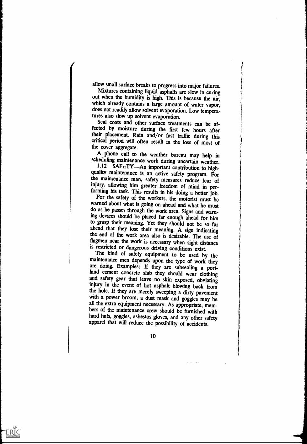
11-9 Compacting the mix 2222
II-11 Cutting vertical face around cracked area.11-12 Brooming plant-mix into alligator cracks 24
11-13 Compacting with vibratory plate compactor 24
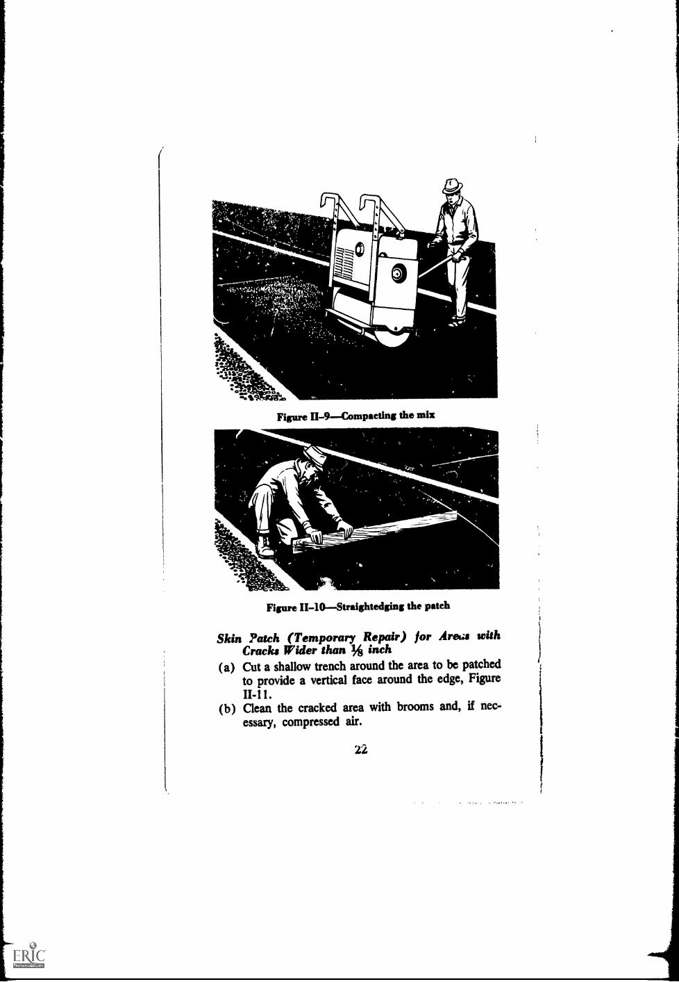
11-14 Applying tack coat 25
11-15 Placing skin patch of hot plant-m11-16 Compacting with vibratory plate compactor 2263
11-17 Spraying asphalt on alligator cracks11-18 Applying cover aggregate11-19 Rolling seal coat with rubber-tired equipment 2278
ix 25
28
11-20 Edge crack 29
11-21 Applying tack coat 30
11-22 Spreading hot plant-mix asphalt material onsettled edge 31
11-23 Compacting with roller 31
11-24 Edge joint crack 32
11-25 Lane joint crack 33
11-26 Reflection crack 34
11-27 Cleaning out crack with broom and air 35
11-28 Sealing with pouring pot and hand squeegee 36
11-29 Sprinkling surface with dry sand 3611-30 Shrinkage cracks 37
11-31 Cleaning shrinkage cracks with compressedair 38
11-32 Applying tack coat 3911-33 Filling shrinkage cracks with slurry seal 40
xi
t
ILLUSTRATIONSContinued11-34 Slurry-sealing the surface 40
11-35 Slippage cracks 41
11-36 Cutting with power saw 42
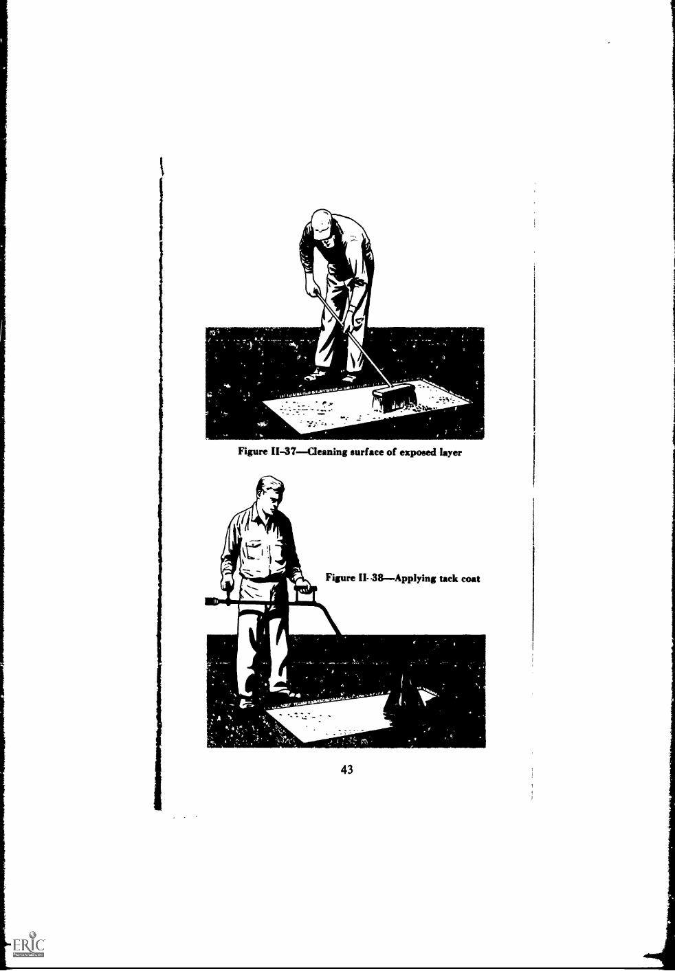
11-37 Cleaning surface of exposed layer 43
11-38 Applying tack coat 43
11-39 Placing plant-mix in cut 44
11-40 Leveling patch mixture 44
11-41 Checking with straightedge 45
11-42 Compacting with roller 45
11-43 Widening crack 46
11-44 Channels (ruts) 47
11-45 Straightedging and outlining channel 48
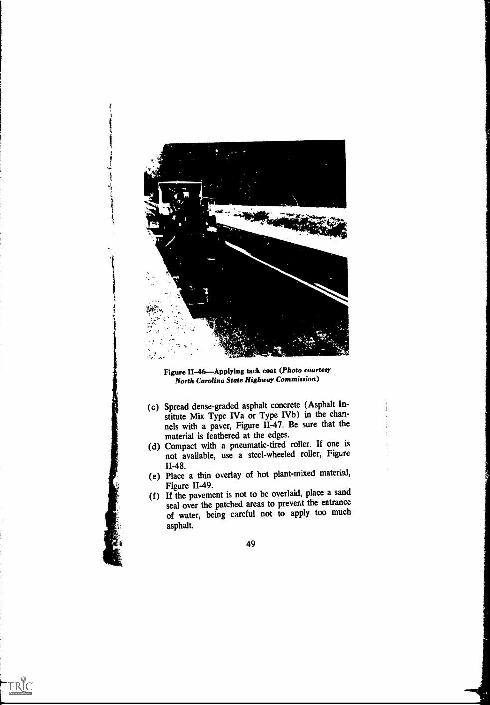
11-46 Applying tack coat 49
11-47 Spreading dense-graded plant-mix 50
11-48 Compacting with roller 50
11-49 Placing thin overlay of hot plant-mix material 51
11-50 Corrugations 52
11-51 Shoving 53
11-52 Planing with a heater-planer 54
11-53 Depression (depressed area is denoted bywater lying on pavement) 55
11-54 Straightedging and outlining depression 57
11-55 Grinding down edge 57
11-56 Cleaning area 58
11-57 Applying tack coat 58
11-58 Spreading plant-mix "1
11-59 Straightedging patch 59
11-60 Compacting patch 6011-61 Placing sand seal 6011-62 Upheaval 61
11-63 Utility-cut depression 6211-64 Pot hole 6311-65 Pot hole permanent repair. (1) Untreated pot-
hole, (2) Surface and base removed to firmsupport (3) Tack coat applied, (4) Full-depth asphalt mixture placed and beingcompacted, (5) Finished patch compactedto level of surrounding pavement 64
xii

ILLUSTRATIONSContinued
11-66 Cleaning hole of loose material 65
11-67 Using infra-red heater 66
11-68 Filling hole with stockpile mixture 67
11-69 Compacting with vibratory plate compactor 67
11-70 Drying patch with infra-red heater 68
11-71 Raveling 69
11-72 Bleeding asphalt 71
11-73 Removing excess asphalt with heater-planer 73
11-74 Applying surface treatment chips 73
11-75 Polished aggregate in pavement surface 74
11-76 Spreading hot plant-mix 75
11-77 Compacting With steel-wheeled roller 76
11-78 Loss of cover aggregate 77
11-79 Longitudinal streaking 79
III-1 Squeegee 83
111-2 Trailer-mounted seal applicator 84
111-3 Shoulder joint 87
111-4 Plowing out old seal 89
111-5 Cleaning with joint-cleaning machine 89
111-6 Blowing out joints 90111-7 Sealing joint 90
111-8 Corner crack 92
111-9 Diagonal crack 93
III-10 Longitudinal crack 94III-11 Restraint crack 95
111-12 Transverse cracks 97
111-13 Fault 99
111-14 Pumping 100
111-15 Blow-up (buckling) 102
111-16 Blow-up (shattering) 102
111-17 Scaling 103
111-18 Spalling 104
111-19 Polished aggregate in pavement surface 106
IV-1 Comparison of new and old liquid asphaltgrades at 140°F (60C) 110
VI-1 Asphalt pouring pot 123

ILLUSTRATIONSContinuodVI-2 Pavement power saw 124VI-3 Pavement cutting disk mounted on motor
grader blade 124VI-4 Infra-red patch heater 125VI-5 Aluminum lute 125VI-6 Heated smoothing iron 126VI-7 Heating kettle with hand spray 126VI-8 Maintenance asphalt pressure distributor 127VI-9 Vibratory plate compactor 177VI-10 Impact compactor 128VI-11 Vibratory roller 129VI-12 Hot roller 130VI-13 Slurry-seal machine 130VI-14 Benkelman beam 131VI-15 Stockpile-mix heater 131VI-16 Small portable mixer 132VI-17 Power router 133VI-18 Shop-made joint-filling device 133VI-19 Asphalt curb machine 134VI-20 Asphalt travel plant 134VI-21 Core-drilling machine 135VI-22 Maintenance asphalt mix spreader 136VI-23 Pavement grinder 137
TABLES
Figure Page111-1 Asphaltic Joint and Crack Sealers for Portland
Cemeat Concrete Pavements 82IV-1 Recommended Uses of Asphalt in Pavement
Maintenance 108Approximate Proportions for Slurry Seal 115Typical Aggregate Gradation for Slurry Seal 115Methods of Testing Aggregate Materials -140, 145Mineral Aggregate Gradations 141, 146
xiv

i
Chapter IINTRODUCTION
1.01 SCOPEThis is a how-to-do-it manual, lim-ited to specific information on the use of asphalt inpavement maintenance. Planning, programming, financ-ing and administration of maintenance are beyond itsscope. Other publications, one of which is Street andUrban Road Maintenance, published by the AmericanPublic Works Association*, cover these phases quitewell.
Pavement maintenance is a major activity of everyhighway and street department. Usually, money formaintenance is limited and the maintenance man iscalled upon to "make one dollar do the work of two."This is not easy.
Large differences in soil types, climate, terrain, trafficand other factors make for greatly varying problems,even within small areas. Some regions are rugged andmountainous while others are fairly smooth and level;some have heavy rainfall, others are semi-arid; somehighways and streets must accommodate vehicles carry-ing coal, ore, logs, or other heavy loads, while othersare subjected to only lightweight traffic.
Yet, despite these differences, there are maintenancemethods that can be used equally well in all regions.Presenting some of these methods is the purpose of thism anual.
1.02 DEFINITIONSSome of the terms used inthis manual are defined here in order that their mean-ings will be clear.
(1) Asphalt ConcreteHigh-quality, thoroughly-controlled hot mixture of asphalt cement and well-graded,high quality aggregate, thoroughly compacted into a uni-
*APWA, 1313 East 60th Street, Chicago, Illinois 60637
1

form dense mass typified by Asphalt Institute Type IVmixes. (See Specifications and Construction Methods forAsphalt Concrete and Other Plant-Mix Types, Specifica-tion Series No. 1 (SS-1), The Asphalt Institute.
(2) Asphalt Emulsion Slurry SealA mixture ofslow-setting emulsified asphalt, fine aggregate and miner-al filler, with water added to produce slurry consistency.
(3) Asphalt Fog SealA light application of slow-setting asphait emulsion diluted with water. It is usedto renew old asphalt surfaces and to seal small cracks andsurface voids. The emulsion is diluted with an equalamount of water and sprayed at the rate of 0.1 to 0.2gallon (of diluted material) per square yard, dependingon the texture and dryness of the old pavement.
(4) Asphalt Leveling CourseA course (asphaltaggregate mixture) of variable thickness u ,ed to elimi-nate irregularities in the contour of an existing surfaceprior to superimposed treatment or construction.
(5) Asphalt OverlayOne or more courses of as-phalt construction on an existing pavement. The overlaygenerally includes a leveling course, to correct the con-tour of the old pavement, followed by uniform courseor courses to provide needed thickness. (Overlays usu-ally are considered construction, not maintenance.)
(6) Asphalt PavementsPavements consisting ofa surface course of mineral aggregate coated and ce-mented together with asphalt cement on supportingcourses such as asphalt bases; crushed stone, slag, orgravel; or on portland cement concrete, brick, or blockpavement.
(7) Asphalt Pavement Structure (sometimescalled Flexible Pavement Structure)Courses of asphalt-aggregate mixtures, plus any non-rigid courses betweenthe asphalt construction and the foundation or sub-grade. [See also (12), (13) and (15) below.]
(8) Asphalt Prime CoatAn application of low-viscosity liquid asphalt to an absorbent surface. It isused to prepare an untreated base for an asphalt surface.
2
1
i
1
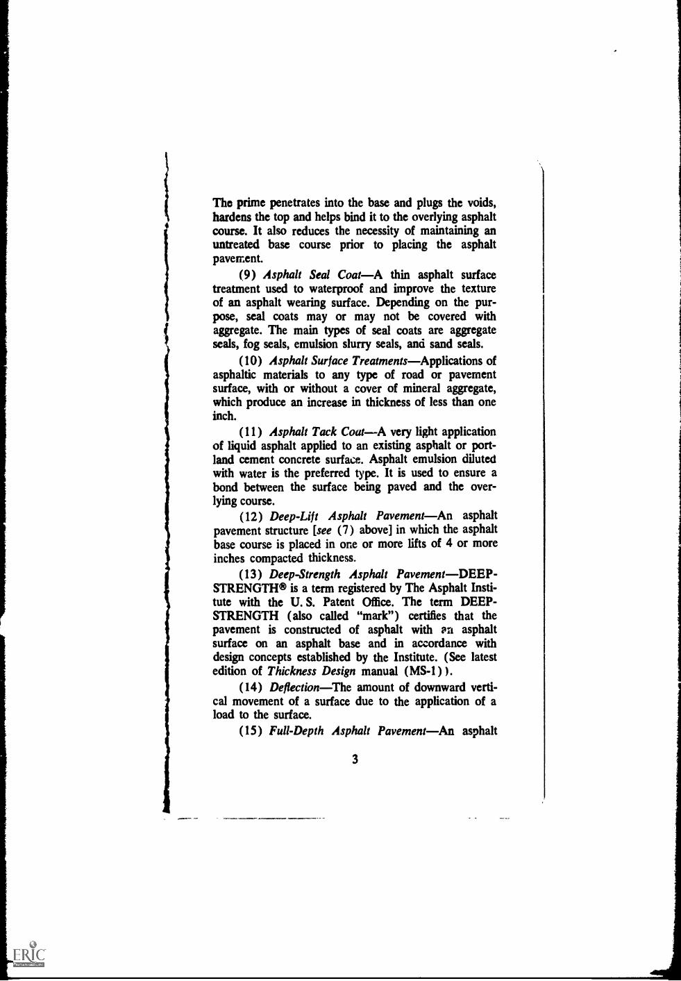
The prime penetrates into the base and plugs the voids,hardens the top and helps bind it to the overlying asphaltcourse. It also reduces the necessity of maintaining anuntreated base course prior to placing the asphaltpavement.
(9) Asphalt Seal CoatA thin asphalt surfacetreatment used to waterproof and improve the textureof an asphalt wearing surface. Depending on the pur-pose, seal coats may or may not be covered withaggregate. The main types of seal coats are aggregateseals, fog seals, emulsion slurry seals, and sand seals.
(10) Asphalt Surface TreatmentsApplications ofasphaltic materials to any type of road or pavementsurface, with or without a cover of mineral aggregate,which produce an increase in thickness of less than oneinch.
(11) Asphalt Tack CoatA very light applicationof liquid asphalt applied to an existing asphalt or port-land cement concrete surface. Asphalt emulsion dilutedwith water is the preferred type. It is used to ensure abond between the surface being paved and the over-lying course.
(12) Deep-Lift Asphalt PavementAn asphaltpavement structure [see (7) above] in which the asphaltbase course is placed in one or more lifts of 4 or moreinches compacted thickness.
(13) Deep-Strength Asphalt PavementDEEP-STRENGTH® is a term registered by The Asphalt Insti-tute with the U. S. Patent Office. The term DEEP-STRENGTH (also called "mark") certifies that thepavement is constructed of asphalt with an asphaltsurface on an asphalt base and in accordance withdesign concepts established by the Institute. (See latestedition of Thickness Design manual (MS-1) ).
(14) DeflectionThe amount of downward verti-cal movement of a surface due to the application of aload to the surface.
(15) Full-Depth Asphalt PavementAn asphalt
3

pavement structure [see (7) above] in which asphaltmixtures are employed for all courses above the subgradeor improved subgrade. A Full-Depth asphalt pavementis laid directly on the prepared subgrade. (The mathe-matical symbol TA denotes Full-depth.)
(16) Mixed-in-Place (Road-Mix)An asphaltcourse produced by mixing mineral aggregate and liquidasphalt at the road site by means of travel plants, motorgraders, drags, or special road-mixing equipment.
(17) Pavement--see Pavement Structure. (As usedin this manual, the word "pavement" means "pavementstructure.")
(18) Pavement StructureAll courses of selectedmaterial placed on the foundation or subgrade soil, otherthan any layers or courses constructed in grading opera-tions.
(19) Plant MixA mixture, produced in anasphalt mixing plant, which consists of mineral aggre-gate uniformly coated with asphalt cement or liquidasphalt.
(20) Plant-Mixed Surface TreatmentsA layer,less than one inch thick, of aggregate that is coated withasphalt in a plant. Plant-mixed surface treatments areused extensively for providing skid-resistant surfaces.
(21) Undersea ling AsphaltA high softening pointasphalt used to fill cavities beneath portland cement con-crete slabs and occasionally to correct the vertical align-ment by raising individual slabs.
1.03 MAINTENANCE DEFINEDPavement main-tenance is not easy to define. Highway departmentsagree in general as to what it is but there are someminor differences, chiefly in scope. Some call pavementimprovement "maintenance." Others include only thework which keeps the pavement in its as-constructedcondition. There also is some disagreement as to whetherrepairs made necessary by unusual events such as earth-quakes, landslides, forest fires, windstorms, or severe traf-fic accidents should properly be classified as maintenance.
4

Takilig all of these into consideration the definitionwhich seems most nearly to fit is:
Pavement maintennce is the routine workperformed to keep a pavement, undernormal conditions of traffic and normall'orces of nature, as nearly as possible inits as-constructed condition.
1.04 WHY MAINTENANCE IS NECESSARYAll pavements require maintenance, the chief reasonbeing that stresses producing minor defects are con-stantly working in all pavements. Such stresses may becaused by change in temperature or moisture content,by traffic, or by small movements in the underlying oradjacent earth. Cracks, holes, depressions, and othertypes of distress are the visible evidence of pavementwear. They are simply the end results of the process ofwear which begins when construction ends. In urbanareas, ditches dug through the pavement for water linesand other utilities are a major cause of pavementmaintenance.
1.05 PREVENTIVE MAINTENANCE"A Stitchin Time . . ."The early detection and repali of minordefects is, without doubt, the most important work doneby the maintenance crew. Cracks and other surfacebreaks, which in their first stages are almost unnoticeable,may develop into serious defects if not soon repaired.This may occur in a very few days on an underdesignedpavement under heavy traffic. For this reason, frequentclose inspections of the pavement should be made byqualified men. Indeed, this measure is necessary towardthe best use of maintenance money.
An inspection made from a moving vehicle, even onewhich creeps, is usually not close enough to detect areaswhere distress may begin. Often the cracks or othersurface defects are so small that only a person on footcan spot them. There are other small signs, such as mudor water on the pavement or shoulder, which to anexperienced observer may signal future trouble. It isbest, then, to walk the pavement for close inspection;
5

or, when there are not enough men available for thispurpose, to spot check selected stretches of roadway.
Upon detection of the warning signs, a detailed in-vestigation, including trenching across the failed area ifnecessary, should be made to determine the kind of repaircalled for. If the pavement seems to be moving undertraffic, deflection measurements should be carried out todetermine the extent of the affected area (see Benkel-man Beam, Chapter II).
All persons making pavement inspections on footshould take proper safety precautions. They should weareasily-seen clothes. They should be protected by adequatewarning signs and devices, or followed by a car ortruck displaying warning devices. Safety flags, vests, andcaps of bright color are very effective.
1.06 DRAINAGE MAINTENANCEA form ofpreventive maintenance is seasonal inspection and clean-ing of drainage systems. If drains are kept workingproperly some of the major causes of pavement damageare eliminated. Each inspection should include all surfacedrainage structures, ditches and channels to insure thatthey are working as designed. If any part of the systemis clogged, it should be cleaned out immediately.
At least twice a year subsurface drains should be ex-amined to make sure they are working as intended.The abnormal appearance of water on the pavementsurface may indicate that subsurface drains are im-properly located, incorrectly designed, or clogged.
All drain outlets should be well marked on theground and on maintenance maps. If this is done theywill not be overlooked on inspection trips.
Detailed information about pavement drainage iscontained in Drainage of Asphalt Pavement Structures,Manual Series No. 15 (MS-15), The Asphalt Institute.Most of the information in this manual applies equallyto portland cement concrete pavements.
1.07 MAKE REPAIRS PROMPTLYRepairsshould be made as quickly as possible after theneed for them is discovered. This is particularly
6

1 important when the detect makes driving hazardous.
Often, weather conditions make temporary iepairs
necessary to prevent further damage until more per-
manent repairs can be made. As examples, crack filling
is most likely to be successful during periods of cool,
dry weather; chuck (pot) hole patches adhere best when
the pavement is warm and dry; and seal coats, or other
surface treatments, require warm and dry weather for
best results. Selecting the best time to make repairs,
therefore, involves the careful balancing of seveial things
and requires both experience and judgment.
1.08 PREVENTION OF DEFECT RECURRENCE
In all cases of pavement distress it is best to deter-
mine first the cause or causes of the difficulty. Then
repairs can be made which will not only correct the
damage but will also, prevent or retard its happening
again. Time and money spent for such repairs are well
spent because the same repairs will not have to be made
over and over.1.09 STREET MAINTENANCEStreet and urban
roads can develop all of the defects discussed in Chap-
ters II and HI. However, some of these defects are much
more of a problem in streets than in any other class of
pavement structure. Shoving and corrugating of asphalt
pavement surfaces, for example, show up more often in
urban areas. Limited speeds on steep grades and frequent
traffic lights and stop signs at intersections multiply the
need for braking and the result is shoving or corrugating
of low stability pavement surfaces. A heater-planer has
been used successfully in repairing these defects (seeCorrugations and Shoving, Chapter II).
A problem almost exclusive to urban areas is that of
utility cuts in the pavement. In most cases these cuts are
made by or for utility companies. And, although repairs
are controlled by municipal regulations, all too often the
backfilled trenches settle, requiring maintenance by the
street department. Settlement can be minimized by select-
ing a well-graded granular backfill and computing it, at
the proper moisture content, with tampers or vibrating
7

compactors. Compacting trench backEl by flooding orpuddling with water is not a good procedure. For this towork at all, the in-place mater1,1 surrounding the excava-tion must be more porous than the backfill material. Andthe backfill materiai must be granular and quite porous it-self.
Utility Cuts, Chapter II, describes a procedure forrepairing these settled patches in asphalt pavemen,s. Thesame procedure is used for portland cement concretepavements. When Full-Depth asphalt concrete is used forthe repair the patch can be completed and openedquickly to traffic. Sometimes winter conditions or otherconsiderations make temporary repairs necessary. Butthere are many utility cuts that cad be permanentlyrepaired the first time.
Often, in growing urban areas, streets become scarredfrom many cuts and patches for utility connections; orthey art weathered and need sealing; or they becomeslippery from polished aggregate or bleeding asphalt.Many cities have found that a thin hot-mix overlay or asurface treatment is the most economical and effectivetreatment for these conditions.
Traffic control usually is more of a problem in urbanareas than in rural areas. Street maintenance, then, mustbe done as quickly and as efficiently as possible withthe least interference to, and from, traffic. Each cityhas its own special problems connected with traffic con-trol and must solve them by its own method. The com-mon goals of all, however, are to minimize disruption oftraffic flow while providing maximum safety for thepublic and the maintenance crew.
1.10 THE IMPORTANCE OF SKILLED MAIN-TENANCE PERSONNELMaintenance work requiresproper supervision, skilled workmen, and good woi!:-manship. Unless all three are employed, it is likely thatsome repair work will be poorly done and may have tobe repeated. Since most pavement repairs involve theuse of asphalt, a thorough knowledge of this material isessential for maintenance men. This is especially true for
8

supervisors and inspectors. Successful pavement main-tenance requires a knowledge of which asphalts are avail-able and how to use them (see Chapter IV). Althoughthe basic skills needed for pavcment maintenance can beacquired only through experience gained in the actualwork, a close study of the literature published by TheAsphalt Institute will be found most useful. The follow-ing publications are recommended for those engaged inmaintenance work:
1. Asphalt as a Material, Information Series No. 93(IS-93).
2. Specifications for Asphalt Cements and LiquidAsphalts, Specification Series No. 2 (SS-2).
3. The Asphalt Handbook, Manual Series No. 4(MS-4).
4. Asphalt Pavements for Airports, Manual Serie3No. 11 (MS-11).
5. Asphalt Surface Treatments and Asphalt Pene-tration Macadam, Manual Series No. 13 (MS-13).
6. Asphalt Mixed-in-Place (Road-Mix) Manual,Manual Series No. 14 (MS-14).
7. Dre,age of Asphalt Pavement Structures, Man-ual &ties No. 15 (MS-15).
1.11 THE IMPORTANCE OF WEATHERPref-erably, patching or resurfacing work should be doneduring warm (50°F and above) and dry weather. Whenhot or warm mixtures are placed on cold pavements, theymay cool so fast that adequate compaction is difficult.This cooling effect is emphasized if the mixture is placedin thin layers. Moreover, asphalt ard asphalt mixturesusually do not bond well to damp surfaces.
This does not mean that repairs cannot be madeduring cold or damp weather. Rather, they require muchgreater care when made during such periods. They alsohave much less chance of being satisfactory. It is better,however, when the safety and comfort of the travelingpublic are concerned, to make the repairs even thoughthey may be only temporary. Also, a delay in repairs may
9
1
allow small surface breaks to progress into major failures.Mixtures containing liquid asphalts are !.low in curing
out when the humidity is high. This is because the air,which already contains a large amount of water vapor,does not readily allow solvent evaporation. Low tempera-tures also slow up solvent evaporation.
Seal coats and other surface treatments can be af-fected by moisture during the first few hours aftertheir placement. Rain and/or fast traffic during thiscritical period will often result in the loss of most ofthe cover aggregate.
A phone call to the weather bureau may help inscheduling maintenance work during uncertain weather.
1.12 SAFI:TYAn important contribution to high-quality maintenance is an active safety program. Forthe maintenance man, safety measures reduce fear ofinjury, allowing him greater freedom of mind in per-forming his task. This results in his doing a better job.
For the safety of the workers, the motorist must bcwarned about what is going on ahead and what he mustdo as he passes through the work area. Signs and warn-ing devices should be placed far enough ahead for himto grasp their meaning. Yet they should not be so farahead that they lose their meaning. A sign indicatingthe end of the work area also is desirable. The use offlagmen near the work is necessary when sight distanceis restricted or dangerous driving conditions exist.
The kind of safety equipment to be used by themaintenance men depends upon the type of work theyare doing. Examples: If they are subsealing a port-land cement concrete slab they should wear clothingand safety gear that leave no skin exposed, obviatinginjury in the event of hot asphalt blowing back fromthe hole. If they are merely sweeping a dirty pavementwith a power broom, a dust mask and goggles may beall the extra equipment necessary. As appropriate, mem-bers of the maintenance crew should be furnished withhard hats, goggles, asbestos gloves, and any other safetyapparel that will reduce the possibility of accidents.
10

IChapter II
MAINTENANCE OF ASPHALT PAVEMENTS2.01 TYPES OF ASPHALT PAVEMENTAsphalt
pavement maintenance as discussed in this chapter ap-plies to all asphalt pavement structures from Full-Depthasphalt to surface treatments (see Definitions, ChapterI). It applies to the traveled way and shoulders of roads,streets, runways and taxiways; to parking lots and aprons;and to other areas such as driveways. Asphalt overlayson portland cement concrete, brick, or other materialsare also included.
This chapter covers the most common types of de-fects and failures in asphalt pavements, their usualcauses, and suggested methods of repair. This does notimply, however, that the subject is completely covered.There may be unusual defects that do not fall into anyof the following categories. There also are many goodmethods of repair that are not described here.
2.02 MOISTURE AND GRANULAR BASESAt the present time many asphalt pavements consistof an asphalt surface over a granular base. The basematerials range from gravel and pit-run products tocrushed and processed rock. These bases serve well aslong as they are properly drained. But if they becomesaturated with water they lose strength rapidly underthe weight and action of traffic.
Saturation of granular bases is the cause of manymaintenance problems. Among them are asphalt-surfaced pavements on granular bases that become softand crack in the familiar alligator or chicken-wire pat-tern. These are problems that won't go away by fillingcracks or placing skin patches. The cause of the distressshould be eliminated.
Many high-type pavements with granular bases aredesigned with drainage systems to prevent saturation by
11

/
ground or surface water. But there are many thousandsof miles of sand-clay-gravel roads, now surfaced withasphalt, that become saturated and give trouble. Usuallythese roads have a high percentage of plastic fine ma-terial in them as binder, needed to hold the materials inplace when the surface was open. As sand-clay-gravelroads they became saturated when it rained but driedout rapidly because moisture was free to evaporate. Withthe addition of the impervious asphalt pavement, thisevaporation through the surface is blocked. The resultis that water migrating into the base materials from theshoulders and from the subgrade below cannot escapeand the sand-clay-gravel loses strength as it becomessoaked. Cracking, heaving, and other forms of distresstake place. Also, in its weakened condition the base,unable to support the traffic, deflects more than normaland cracking is intensified.
Therefore, when investigating surface failures whichappear to be related to excessive deflection (see Defini-tions, Chapter I), the base should be checked for plasticfines or trapped water. If so, repair may call for diggingout the broken area to sound material, improving drain-age, and patching with asphalt patching mixture (Chap-ter IV).
2.03 BENKELMAN BEAMThe extent of areasof excessive deflection can be determined quite easilywith a device called the Benkelman Beam. This device,pictured in Figure II-1, has a narrow beam that isslipped between the dual tires of the rear axle of aloaded truck. A foot on the end of the beam restson the pavement between the tires. The truck movesahead at creep speed and the total pavement rebounddeflection is read by means of a dial gauge. (Rebounddeflection is the amount of vertical rebound of a surfacethat occurs when a load is removed from the surface.)
Rebound deflection readings should be taken at loca-tions sufficient to outline the whole area of excessivedeflection before repairs are made. Areas of excessive de-flection may be estimated by comparing deflection in the
12

A
distressed area with the average deflection in areas thatare performing well. See Appendix B for details ofthe deflection test procedure.
&Mow- ,151 4+ 4-,17
w4.16.;.a.. k.
Figure II-1Benkelman beam (Photo courtesy U.S.Bureau of Public Roads)
2.04 PATCHING MIXTURES Many patchesbleed, become unstable, and are subject to pushing afterplacement. The cause usually is an excess of asphalt inthe patching mixture. Patch instability can also be causedby not allowing the patch (when made with a stockpiledpatching mixture) to cure before subjecting it to traffic.
For the best patching mixture a laboratory investiga-tion should be made of the materials proposed for use(see Appendix A for specifications).
High-quality hot-mixed patching mixtures, althoughcosting more than other patching materials, result inlonger-lasting patches. The major cost of patching liesin placing the patch, not in the cost of the material.Therefore, the use of hot-mix materials for patches out-lasting many times those made with other materials is areadily-apparent economy.
It is usually possible to get a hot asphalt mixture forpatching, even in out-of-the-way areas. One method
13

/
employs a mix-heater to heat stockpiled pre-mix priorto making the patch. There are several types of theseheaters. One type can be suspended from the tailgate ofthe truck carrying the pre-mix. Another is trailermounted.
Also available is a small portable mix-plant designedfor small jobs and maintenance operations. It is equippedwith a small dryer and pugmill. Asphalt is stored in atank on the mix-plant trailer. Aggregate usually iscarried in a truck towing the plant. Output at jobsite is5-10 tons per hour of hot-mix material.
2.05 PRIME AND TACK COATSIf the base ofa deep patch is made with untreated material it shouldbe primed with 0.20 to 0.30 gallon per square yard ofliquid asphalt. If spray equipment is not available, handmethods can be used to apply the prime. But care mustbe taken not to apply an excess of asphalt. The amountof asphalt material used to prime the base should beonly enough to knit together the top particles.
The prepared edges of the surface surrounding thearea being patched should be tack coated to ensure abond between them and the patch material.
If the prime and tack coat are of asphalt emulsion,enough time should be allowed for the emulsion to"break" and most of the water to dry out before thepatch-mix is placed. Similarly, a rapid curing or medium-curing asphalt should be given time to penetrate andcure before the patch mix is placed.
For a surface patch, a light tack coat is necessary.A slip plane may develop from either the absence of atack coat or too heavy a tack coat. Application methodsare similar to those used for a prime coat except that thequantities used are much smaller.
2.06 PLACING PATCHING MIXTURESAfterthe area to be patched has been properly prepared,including trimming of edges and applying the correctprime coat or tack coat, there remains only the placingand compacting of the mix.
14
[

Segregation should be prevented. Patching mixtureshould never be dumped from the truck into the patcharea. It should be shoveled directly from the truck orfrom a board on to which it has been dumped. Theshovels-full of mix should be placed against the edgesfirst rather than piled in the center and raked to theedges.
It should never be necessary to pull material fromthe center of the patch to the edge in making the joint.If more material is needed at the edge it should bedeposited there and the excess raked away. The quan-tity of material placed in the patch area should besufficient to ensure that, after compaction, the patchsurface will not be below that of the adjacent pavement.However, if too much material is placed in the patcharea a hump will result. A stringline and/ or a straight-edge, used properly, can be a great help in producing asmooth riding surface. (See Figure 11-2, Placing Patch-ing Mixture.)
4-1-
_J
7
A v. .
Figure 11-2Placing patching mixture
2.07 COMPACTING PATCHING MIXTURESIn compacting the patch, the first pass and return ofthe roller, vibratory compactor, or maintenance truckwheels (if these are used) should overlap not more than6 inches on to the patch material at one edge. Thisshould then be repeated on the opposite side to compact
15

the material into the edge joints. Compaction should thenproceed from the low side to the high side, with eachpass and return lapping an additional few inches on tothe patch. When proper equipment and procedures areused the surface of the patch should be at the samegrade as the surrounding pavement. If hand tampingor other light compaction methods are used, however,the surface of the completed patch should be slightlyhigher than the pavement. Traffic will compress thepatch further. (Figure 11-3, Compacting Patching Mix-ture.)
::11. I,
am&
Figure 11-3Compacting patching mixture
16
0

A. Cracking
2.08 GENERALCracking takes many forms.Simple crack filling may be the right treatment in somecases. In others, complete removal of the affected areaand the installation of drainage may be necessary beforeeffective repairs can be carried out. To make properrepairs, then, the necessary first step is to determine thecause of cracking.
The repair techniques for the correction of variousforms of cracking discussed in this section are notnecessarily the only correct ways to do the job. But theyare proven ways that should result in neat, long-lastingrepairs.
2.09 ALLIGATOR CRACKSThese are intercon-nected cracks forming a series of small blocks resem-bling an alligator's skin or chicken-wire, Figure 11-4.
Figure 11-4Alligator cracks
17

(1) CauseIn most cases, alligator cracking iscaused by excessive deflection of the surface over un-stable subgrade or lower courses of the pavement. Theunstable support usually is the result of saturated gran-ular bases or subgrade. The affected areas in most casesare not large. Sometimes, however, they will cover entiresections of a pavement. When this happens, it probablyis due to repeated loads that exceed the load-carryingcapacity of the pavement.
(2) RepairSince alligator cracking usually isthe result of saturated bases or subgrades, correctionshould include removing the wet material and installingneeded drainage. Asphalt plant-mixed material canthen be used for the full depth for a strong patch. (Thismay be the least expensive repair because of the singleoperation with one material.) If the asphalt plant-mixedmaterial is not available, new granular base material inlayers not exceeding six inches each are compacted in.The granular base should then be primed and patched.
When necessary, temporary repairs can be made byapplying skin patches or aggregate seal coats to theaffected areas. In any event, repairs should be madepromptly to avoid further damage to the pavement.
In the case of cracking from overloading, a properly-designed overlay will correct the condition. Refer toA Short, Practical Guide to the Design of AsphaltOverlays, Information Series No. 139 (IS-139), TheAsphalt Institute.
Deep Patch (Permanent Repair)
(a) Remove the surface and base as deep as neces-sary to reach firm support, extending at least afoot into rood pavement outside the cracked area,Figure 11-5. This may mean that some of the sub-grade will also have to be removed. Make the cutsquare or rectangular with far-Gs straight mid
18

1vertical. One pair of faces should be at rightangles to the direction of traffic. A pavement sawmakes a fast and neat cut.
(b) If water is a cause of the failure, install drainage.
(c) Apply a tack coat to the vertical faces, Figure 11-6.
(d) For best results, backfill the hole with a dense-graded hot asphalt plant-mix. Figure 11-7. Spreadcarefully to prevent segregation of the mixture,Figure 11-8.
If the asphalt mixture is not available, make thebackfill with a pod granular base material. Part ofthe surfa k.:. and upper base material removed fromthe hole, broken into small pieces and mixedthoroughly, can be placed in the bottom of the hole.
(e) Compact in layers if the hole is more than 6 inchesdeep. Compact each layer thoroughly, Figure 11-9.Compaction should be done with equipment mostsuited for the size of the job. A vibratory platecompactor is excellent for small patches. A rollermay be more practical for large areas.
(f) Full-Depth asphalt mix placed directly on the sub-grade needs no prime.
(g) If granular base is used it should be primed. Therepair is then completed by placing hot plant-mixedasphalt surfacing material, and compacting to thesame grade as the surrounding pavement. If hot-mixed surfacing is not available, plant-mixed ma-terial using liquid asphalt can be used.
(h) Use a straightedge or a stringline to check the rid-ing quality and the alignment of the patch, FigureII-10.
19

a :eke.
...
V
- - a.agelkor _. . - -
-
st#:4741%.
Figure II-5---Removing surface and base
- 0.me.
.4. 44..-1,31
-41/41316risit
4
Figure II-6Applying tack coat to vertical surfaces
20

44.2.,
-
,
...-.
Figure II-7Backfilling hole with plant-mix
;se
Figure II-8Spreading the mix
21
-.32.txrada°
Figure II-9--Compacting the mix
9-
WEIte&
-
Figure II-10--Straightedging the patch
Skin Patch (Temporary Repair) for Areas withCracks Wider than inch
(a) Cut a shallow trench around the area to be patchedto provide a vertical face around the edge, FigureII-11.
(b) Clean the cracked area with brooms and, if nec-essary, compressed air.
22

(c) Broom plant-mixed fine-graded asphalt materialinto cracks, Figure 11-12.
(d) Compact with a vibratory plate compactor orroller, Figure 11-13, or roll with rear wheel of aloaded truck.
(e) Apply a tack coat, Figure 11-14.(f) Place a skin patch with hot plant-mixed asphalt
material, Figure 11-15. If this material is not avail-able, use plant mix with liquid asphalt. Featherthe edges carefully, removing coarse particles withlute and rake before compaction.
(g) Compact the patch with a vibratory plate com-pactor or roller, Figure 11-16. If neither is avail-able, rolling may be done with the wheels of thetruck that carries the mix.
Figure II-11Cutting vertical face around crackedarea
23

_t :
'
4
0014IMOIN14=11.11I 4111.111114111111M~.044
ifr
JAILlitialange.11141111111touissuasinou MIIIV !ow itliwziaa to WallMI &Mit'
at.
411111111..111011111
i-
. pkit,i,t,iiii,,....4,,..
or-----,,T10...L.--*---'",--Ti
IMAIMsnummavi &Wilma [um IJA:11111111111VAIIIIIL111111,WAIUM
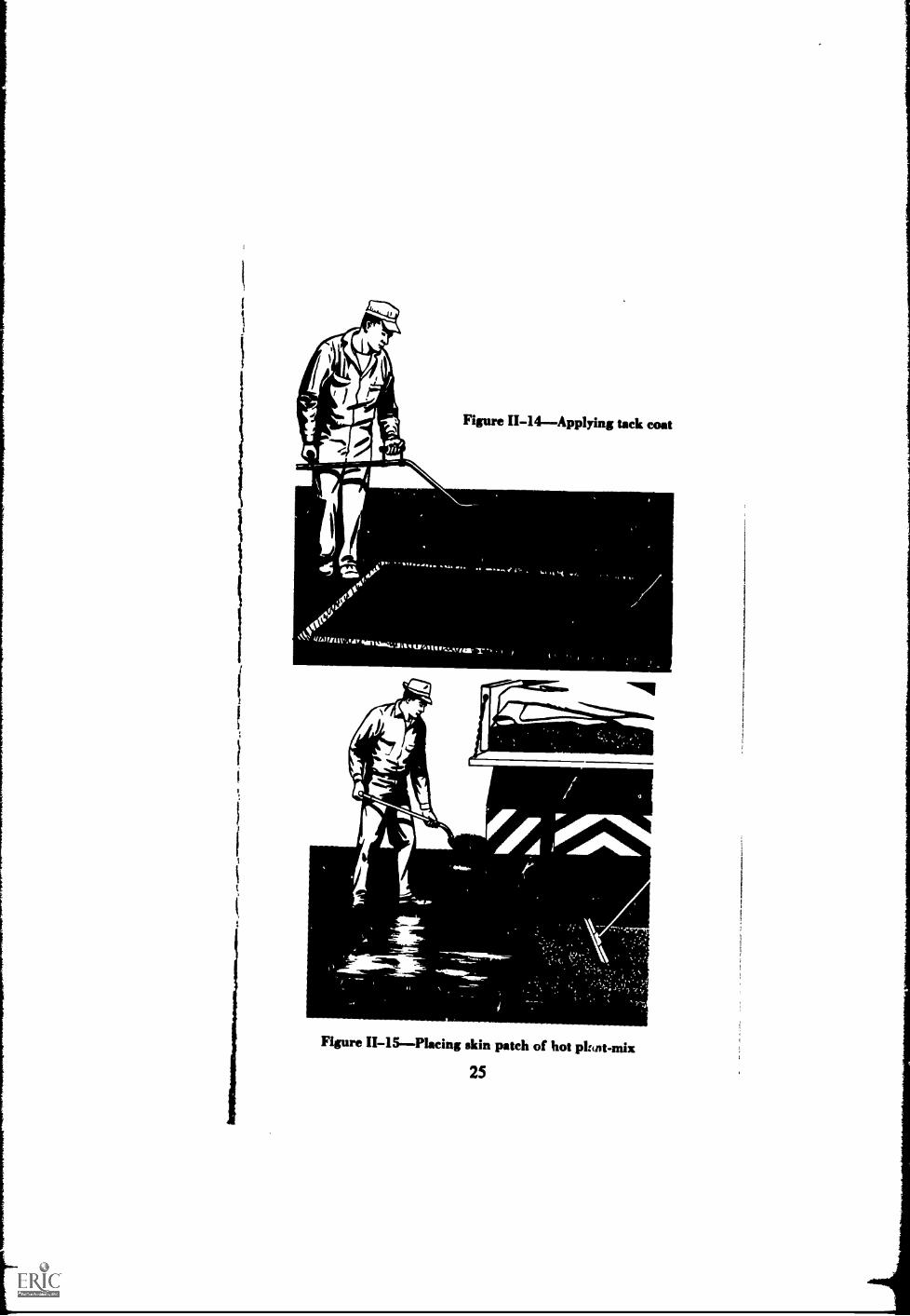
Figure II-14Applying tack coat
t
_ -
Figure II-15Placing skin patch of hot picot-mix
25
,
, ,.. ../INININIs-
Figure II-16--Compacting with vibratory platecompactor
1
Aggregate Seal Coat Patch (Temporary Repair) forAreas with Cracks Narrower than 1/8 inch
(a) Clean the cracked area with brooms and, if neces-sary, compressed air.
(b) Spray the necessary amount of liquid asphalt(either emulsion rapid curing, or medium curing)on to the cleaned area, Figure 11-17. Usually,0.15 or 0.25 gallon per square yard is enough forthe seal coat, but, if an excessive amount is lostin the cracks, slightly more asphalt should beapplied.
26
\
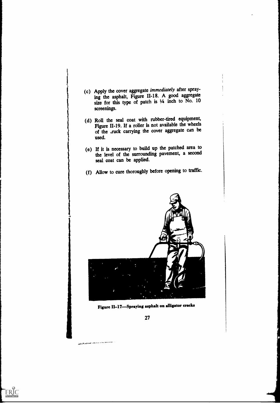
(c) Apply the cover aggregate immediately after spray-
ing the asphalt, Figure 11-18. A good aggregatesize for this type of patch is Y4 inch to No. 10screenings.
(d) Roll the seal coat with rubber-tired equipment,Figure 11-19. If a roller is not available the wheelsof the auck carrying the cover aggregate can be
used.
(e) If it is necessary to build up the patched area tothe level of the surrounding pavement, a secondseal coat can be applied.
(f) Allow to cure thoroughly before opening to traffic.
Figure II-17Spraying asphalt on alligator cracks
27
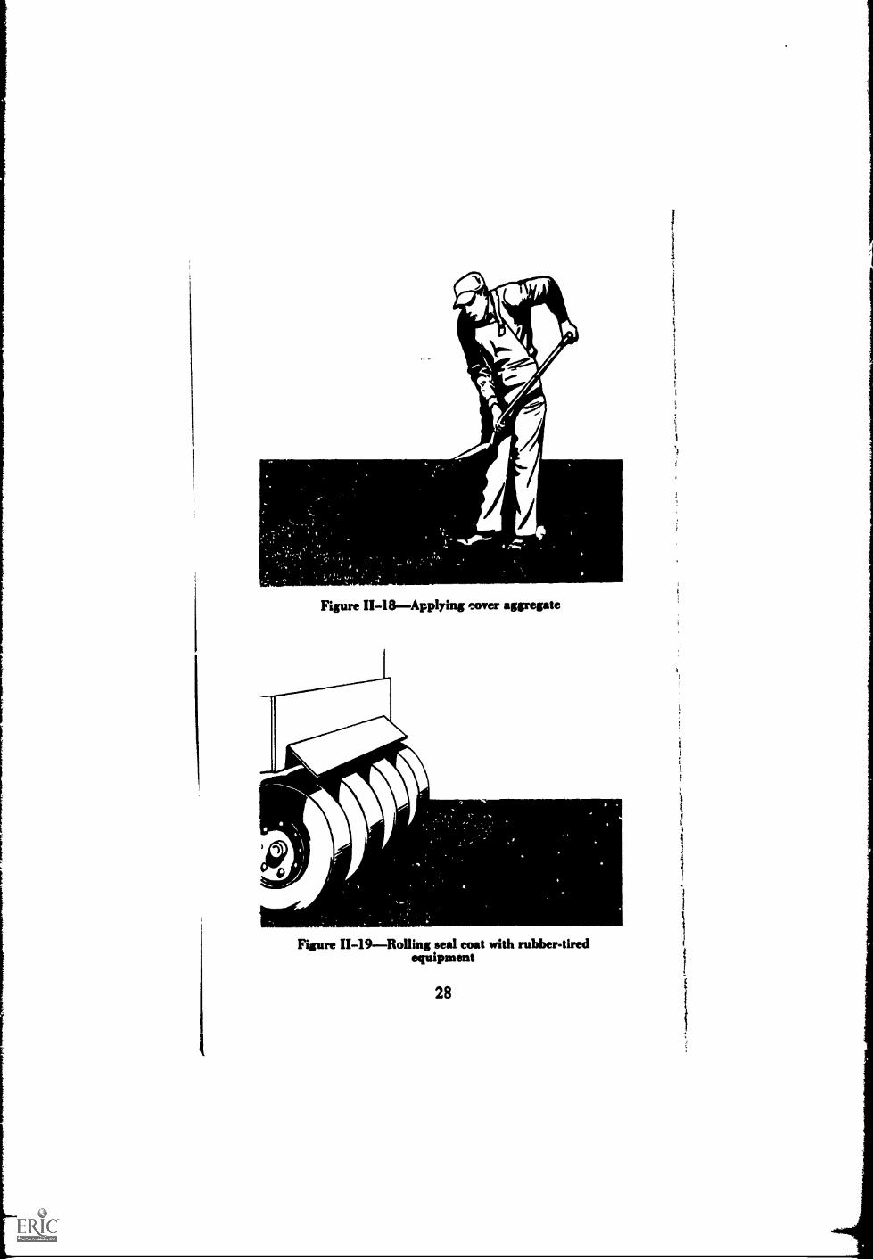
Figure II-18Applying cover aggregate
Figure 11-19Rolling seal coat with rubber-tiredequipment
28

i
1
1
i
i
1
)
i
1
1
Slurry Seal Patch (Temporary Repair) for AreasCracked from Overloading
(a) Clean the cracked area with brooms and, if neces-sary, compressed air.
(b) Apply an asphalt emulsion slurry seal according toSpecification ST-3, Asphalt Surface Treatments andAsphalt Penetration Macadam, Manual Series No.13 (MS-13), The Asphalt Institute.
2.10 EDGE CRACKSThese are longitudinal cracksa foot or so from the edge of the pavement, with or with-out transverse cracks branching towards the shoulder,Figure 11-20.
-*
Figure 11-20Edge crack (Photo courtesy OhioHighway Department)
(1) CauseUsually, edge cracks are due to lackof lateral ( shoulder) support. They may also be causedby settlement or yielding of the material underlying thecracked area; which in turn may be the result of poordrainage, frost heave, or shrinkage from drying out ofthe surrounding earth. In the last case trees, bushes orother heavy vegetation close to the pavement edge maybe a cause.
29

(2) RepairFor temporary repair, fill as for re-flection cracks. For more permanent repair, fill crackswith asphalt emulsion slurry or liquid asphalt mixedwith sand. If the edge of the pavement has settled, bringup to grade with hot plant mix patching material.(a) Improve drainage. Install underdrains, if necessary.(b) Clean pavement and cracks with broom and com-
pressed air.(c) Fill cracks with emulsiom slurry or liquid asphalt
(SS-1, SS-1h, or SM-K) mixed with sand. Wipewith a rubber-edged squeegee.
(d) Apply a tack coat, Figure 11-21.(e) Bring settled edge up to grade by spreading hot
asphalt plant-mixed material, Figure 11-22. Checkthe smoothness with a straightedge or a stringline.Compact with a vibrating plate compactor or aroller, Figure 11-23. Be sure that tne edges of thepatch are straight and neat.
(f) Remove trees, shrubs, and other vegetation exceptgrass from close to the pavement edge.
0..4"14
Figure II-21Applying tack coat
30

1
Figure 11-2 preading hot plant-mixed asphalt
material on settled edge
Figure 11-23Compacting with roller
31

2.11 EDGE JOINT CRACKSAn edge joint crackis really a seam. It is the separatien of the joint betweenthe pavement and the shou'der, Figure 11-24. It is treatedas a crack, however.
a
1
Figure 11-24Edge joint crack
(1) CauseA common cause of "cracking" in apavement-shoulder joint is alternate wetting and dryingbeneath the shoulder surface. This may result from poordrainage due to a shoulder higher than the main pave-ment, from a ridge of grass or joint-filling material, orfrom depressions in the pavement edge, all of whichtrap water and allow to stand along and seep throughthe joint. Other causes are shoulder settlement, mixshrinkage, and trucks straddling the joint.
(2) RepairIf water is the cause, the first stepis to improve the drainage by getting rid of the conditionthat traps water. Then repair the crack, see ReflectionCracks below.
32I
1
1
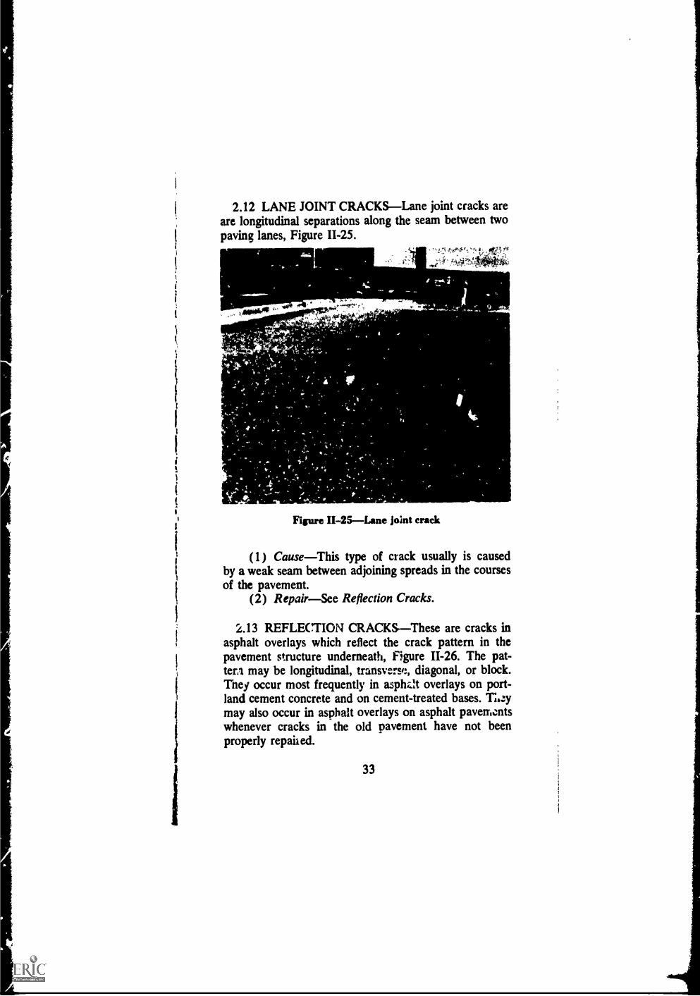
i2.12 LANE JOINT CRACKSLane joint cracks are
are longitudinal separations along the seam between two
i paving lanes, Figure 11-25.i
i
it
i
I
MN.
Figure II-25Lane joint crack
(1) CauseThis type of crack usually is causedby a weak seam between adjoining spreads in the coursesof the pavement.
(2) RepairSee Reflection Cracks.
2.13 REFLECTION CRACKS--These are cracks inasphalt overlays which reflect the crack pattern in thepavement structure underneath, Figure 11-26. The pat-tern may be longitudinal, transverse, diagonal, or block.Tney occur most frequently in asphzh overlays on port-land cement concrete and on cement-treated bases. Tuzymay also occur in asphalt overlays on asphalt pavementswhenever cracks in the old pavement have not beenproperly repaiied.
33

(1) CauseReflection cracks are caused by verti-cal or horizontal movements in the pdvement beneaththe overlay, brought on by expansion and contractionwith temperature or moisture changes. They may becaused also by traffic or earth movements and by lossof moisture in subv ades with high clay contents.
IL,
Figure 11-26Reflection crack
34
1

1
I
(2) RepairSmall cracks (less than 1/2 in. inwidth) are too small to seal effectively. Large cracks (1/2in. and over in width) are to be filled with asphJt emul-sion slurry or light grade of liquid asphalt mixed withfme sand. Also, special asphalt compounds or heavierbodied asphalt material may be used to fill large cracks.
(a) Clean out crack with stiff-bristled broom and com-pressed air, Figure 11-27.
(b) Large crack. Using a hand squeegee and a broom,fill (do not overfill) with emulsion slurry or liquidasphalt (SS-1; SS-1h, or SM-K) mixed with sand.When cured, seal With liquid asphalt using a pour-ing pot and a hand squeegee, Figure 11-28.
(c) Sprinkle surface of crack filler with dry sand toprevent pick-up by traffic, Figure 11-29.
_
I\ ,
I _
,
Figure II-27--Cleaning out crack with broom and air
35

Figure 11-28Sealing with pouring pot and handsqueegee
sAt
- 'cl
Figure 11-29Sprinkling surface with dry sand
36

2.14 SHRINKAGE CRACKSShrinkage cracks areinterconnected cracks forming a series of large blocks,usually with sharp corners or angles, Figure 11-30.
Figure 11-30Shrinkage cracks
(1) CauseOften it is difficult to determine wheth-er shrinkage cracks are caused by volume change in theasphalt mix or in the base or subgrade. Frequently,they art caused by volume change of fine aggregateasphalt mixes that have a high content of low penetrationasphalt. Lack of traffic hastens shrinkage cracking inthese pavements.
(2) RepairFill cracks with asphalt emulsionslurry followed by a surface treatment or a slurry sealover the entire surface. (Refer to The Asphalt Institute'sSpecification ST4 or Specification ST-3, Asphalt SurfaceTreatments and Asphalt Penetration Macadam, ManualSeries No. 13.)
37

(a) Remove all loose matter from the cracks and pave-ment surface with brooms and compressed air,Figure 11-3 1.
(b) Wet with water the surface of the pavement and allcrack faces.
(c) When all surfaces are uniformly damp, with no freewater, apply a tack coat of asphalt emulsion dilutedwith equal parts of water, Figure 11-32.
aliaAirr
^:,**-
r.
,
-
.^
v
Figure II-31--Cleaning shrinkage cracks withcompressed air
38
141-.
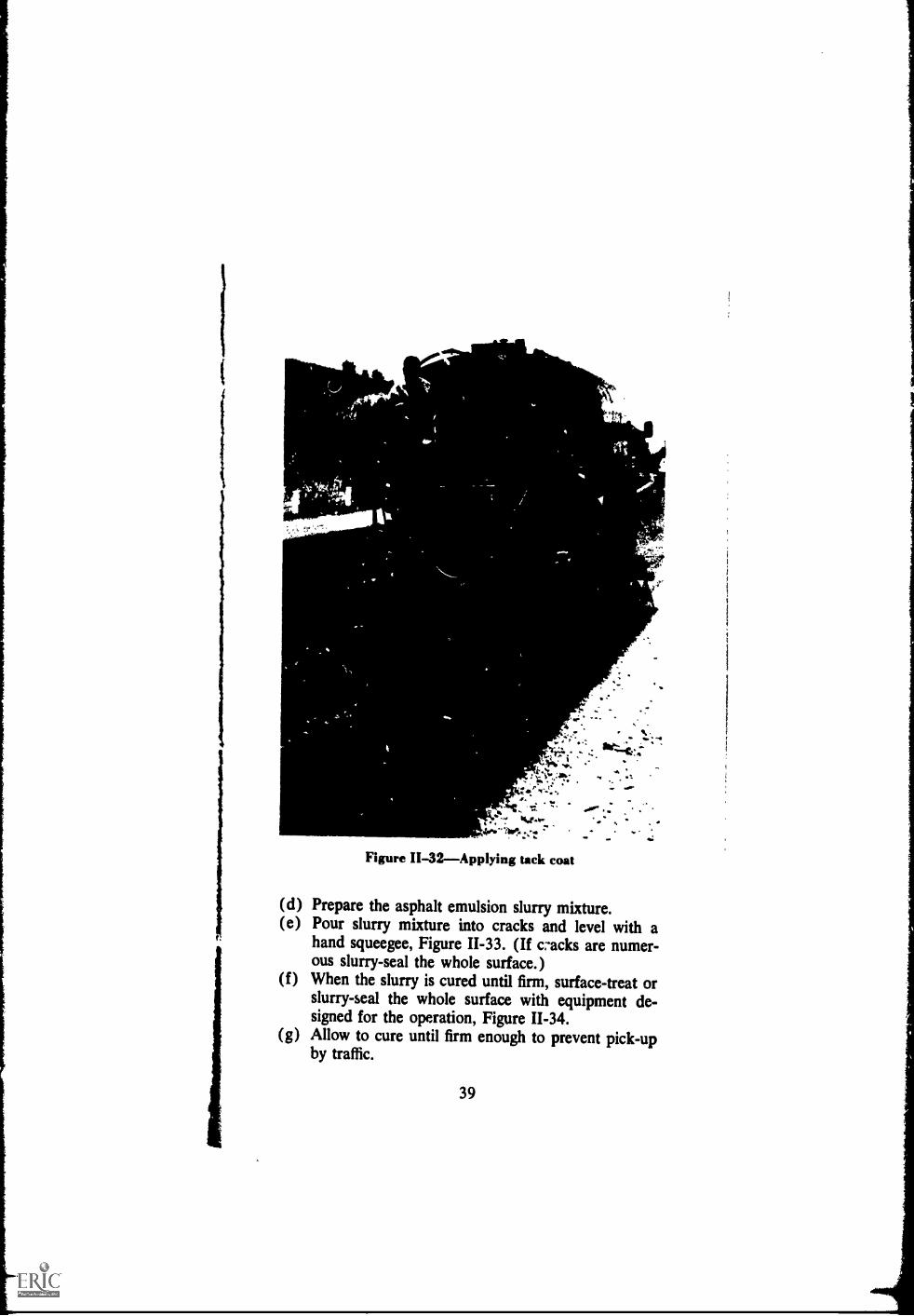
Figure 11-32Applying tack coat
,01100"
10
(d) Prepare the asphalt emulsion slurry mixture.(e) Pour slurry mixture into cracks and level with a
hand squeegee, Figure 11-33. (If cracks are numer-ous slurry-seal the whole surface.)
(f) When the slurry is cured until firm, surface-treat orslurry-seal the whole surface with equipment de-signed for the operation, Figure 11-34.
(g) Allow to cure until firm enough to prevent pick-upby traffic.
39

,
Masa
eViz,
Figure II-33Filling shrinkage cracks with slurrysee,
MIL-Amer_
'
Figure II-34--Slurry-sealing the stzrface
40

2.15 SLIPPAGE CRACKSThese are sometimescrescent-shaped cracks that po 1 in the direction of thethrust of wheels on the pavement surface, Figure 11-35.Thir does not mean that they invariably point in thedirection that ti affic is going. For example, if brakes areapplied on a vehicle going down a hill the thrust of thewheels is reversed. Slippage occurring in this circum-stance will result in cracks pointing uphill.
Figure II-35Slippage cracks
(1) CauseSlippage cracks are caused by the lackof a good bond between the surface layer and the coursebeneath. The lack of bond may be due to dust, oil, rub-ber, dirt, water, or other non-adhesive material betweenthe two cemrses. Usually, such a lack of bond exists whenno tack coat has been used. Slippage cracks may alsobe due to a mixture having a high sand content, andthey can occur whether the sand is sharp or rounded.Sometimes slippage may develop under traffic becauseimproper compaction during construction caused thebond layers to be broken.
(2) RepairThe only proper way to repair aslippage crack is to remove the surface layer fromaround the crack to the point w}:ere good bond between
41

r the layers is found. Then patch the area with plant-mixed asphalt material.(&) Remove the slipping area and at least one foot into
the surrcunding well bonded pavement. Make thecut faces straight and vertical. A power pavementsaw makes a fast and neat cut, Figure 11-36.
(b) Clean the ?surface of the exposed underlying layerwith brooms and compressed air, Figure 11-37.
(c) Apply a light tack coat, Figure 11-38.(d) Place enough hot plant-mixed asphalt material in
the cut-out area to make the surface the same gradeas the surrounding pavement when it is compacted,Figure 11-39.
(e) Level the mixture carefully to prevent segregation,Figure 11-40.
Figure 11-36--Cutting with power saw
42
_
Figure 11-37Cleaning surface of exposed layer
Figure 11-48Applying tack coat
43

Figure II-39Placing plant-mix in cut
.
Figure II-40--Leveling patch mixture
44

1
(f) Check the riding quality of the patch with a straight-edge or a stringline. Figure 11-41.
(g) Compact thoroughly with a vibrating plate com-pactor or a steel-wheeled roller, Figure 11-42.
Figure II-41Cheeking with straightedge
Figure II-42Compacting with roller
45
N

2.16 WIDENING CRACKSWidening cracks arelongitudinal reflection cracks that show up in the as-phalt overlay above the joint between the old and new
sections of a pavement widening, Figure II-43.(1) Causesee Reflection Cracks (Article 2.13).(2) Rcpairsee Reflection Cracks (Article 2.13).
Figure 11-43Widening crack
46

B. Distortion
2.17 GENERALPavement distortion is any changeof the pavement surface from its original shape. It usu-ally is caused by such things as too little compaction ofthe pavement courses, too many fines in surface mixtures,too much asphalt, swelling of underlying courses, or set-tlement. Like cracks, distortion takes a number of differ-ent forms: grooves or ruts, shoving, corrugations, de-pressions, upheaval. As with any other defect, the typeof distortion and its cause must be determined beforethe correct remedy can be applied. Repair techniquesrange from leveling the surface by filling with newmaterial to complete removal of the affected area andreplacing with new material.
2.18 CHANNELS (RUTS) These are channelizeddepressions which moy develop in the wheel tracks ofan asphalt pay ment, Figure 11-44.
Figure II-44Channe1 s (ruts)
47

(1) CauseChannels may result from consolida-tion or lateral movement under traffic in one or more ofthe underlying courses, or by displacement in the asphaltsurface layer itself. They may develop under traffic innew asphalt pavements that had too little compactionduring construction. They may develop from plasticmovement in a mix that does not have enough stabilityto support the traffic.
(2) RepairLevel the pavement by filling thechannels with hot plant-mixed asphalt material. Followwith a thin asphalt plant-mix overlay.(a) Determine the limits of channels with a straightedge
or stringline, Figure 11-45. Outline with a crayon'he areas to be filled.
Figure II-45Straightedging and outlining channel(Photo courtesy North Carolina State Highway
Commission)
(b) Apply a light tack coat (0.05 to 0.15 gallon persquare yard of SS-1 or SS-lh asphalt emulsiondiluted with equal parts of water). See Figure 11-46.
48
,
Mit
Figure 1I-46Applying tack coat (Photo courtesyNorth Carolina State Highway Commission)
(c) Spread dense-graded asphalt concrete (Asphalt In-stitute Mix Type IVa or Type IVb) in the chan-nels with a paver, Figure 11-47. Be sure that thematerial is feathered at the edges.
(d) Compact with a pneumatiodred roller. If one isnot available, use a steel-wheeled roller, FigureII-48.
(e) Place a thin overlay of hot plant-mixed material,Figure 11-49.
(f) If the pavement is not to be overlaid, place a sandseal over the patched areas to prevent the entranceof water, being careful not to apply too muchasphalt.
49
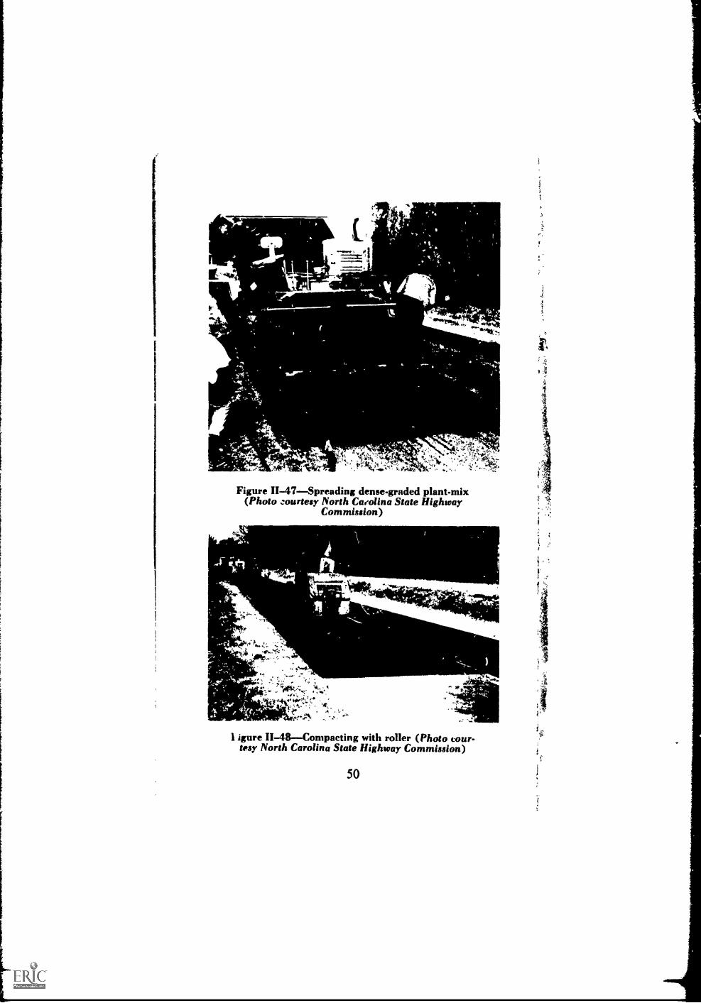
Figure II-47Spreading dense-graded plant-mix(Photo zourtesy North Carolina State Highway
Commission)
...OM/' NoLis*,
, *OttVi...ttr!,,,
^^
1 igure II-48Compacting with roller (Photo cour-tesy North Carolina State Highway Commission)
50

44.; .
Figure II-49Placing thin overlay of hot plant-mixmaterial (Photo courtesy North Carolina State
Highway Commission)
2.19 CORRUGATIONS AND SHOVINGCorru-gations (sometimes called "washboarding") is a formof plastic movement typified by ripples across the asphaltpavement surface, Figure 11-50. Shoving is a form ofplastic movement resulting in localized bulging of thepavement surface, Figure 11-51. These occur usually atpoints where traffic starts and stops, on hills wherevehicles brake on the downgrade, on sharp curves, orwhere vehicles hit a bump and bounce up and down.
(1) CauseCorrugations and shoving usually oc-cur in asphalt layers that lack stability. Lack of stabilitymay be caused by a mixture which is too rich in asphalt,has too high a proportion of fine aggregate, has coarseor fine aggregate which is too round or too smooth tex-tured, or has asphalt cement which is too soft. It may
51
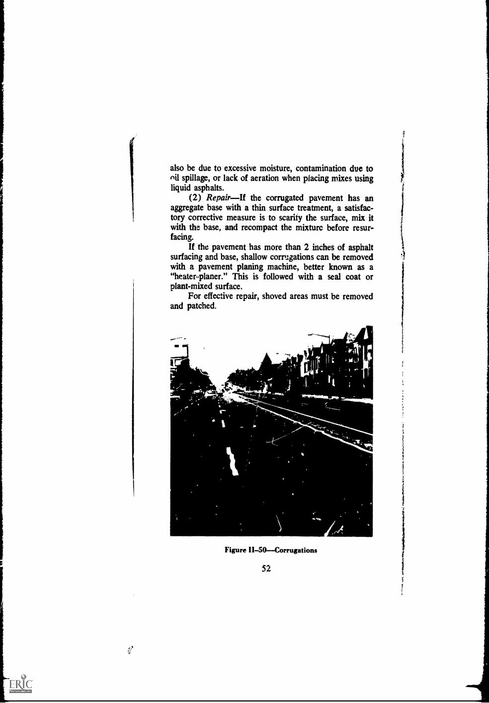
also be due to excessive moisture, contamination due tonil spillage, or lack of aeration when placing mixes usingliquid asphalts.
(2) RepairIf the corrugated pavement has anaggregate base with a thin surface treatment, a satisfac-tory corrective measure is to scarify the surface, mix itwith the base, and recompact the mixture before resur-facing.
If the pavement has more than 2 inches of asphaltsurfacing and base, shallow corrugations can be removedwith a pavement planing machine, better known as a"heater-planer." This is followed with a seal coat orplant-mixed surface.
For effective repair, shoved areas must be removedand patched.
..mr"
7.-444ksysi
Figure II-50Corrugations
52

,
, . ..#1.-+";
'k, " .., .6'01 z
., . iti'R"' :41- , VP,
+. 4.40,
"11,k
Figure II--51Shoving
z."+,
as*,
0
4/6:-,t
;**'.
Repair of Corrugations in a Thin Surface Treat-ment:
(a) Scarify and break up the surface with a rotary tiller.(b) Mix the broken-up surface material with the base
material to a depth of 4 inches.(c) Compact and reshape the base.(d) Prime the base.(e) Apply a new surface treatment.
53

Repair of Corrugations in a Thick Asphalt Surface:
(a) Plane to a smooth surface with a heater-planer, Fig-ure 11-52. If a paved gutter line must be met, cut ashoulder with the heater-planer. The shouldershould be the thickness of the seal coat to follow,so that the edges will not have to be feathered.
(b) Cover 'he planed surface with a hot plant-mixedasphalt seal coat or an asphalt emuHon slurry seal(or an asphalt concrete everlay if one is needed).
Repair of Shoved Areassee Alligator CracksDeep Patch (Article 2.09)
SC--;
01..
4';
r-rats4 B
-.711
Figure II-52Planing with a heater-planer
2.20 GRADE DEPRESSIONSDepressions are lo-calized low areas of limited size which may or may notbe accompanied by cracking, Figure II-53. They dip aninch or more below grade and water will collect in them.
54

These "birdbaths" are not only a source of Ideterioration but are a hazard to motorists,in freezing weather.
(1) CauseDepressions may be cause,heavier than that for which the pavement wasby settlement of the lower pavement layers, or by poorconstruction methods.
Figure II-53--Depression (depreswd areadenoted by water lying on pavement)
55
(2) RepairDepressions should be filled with hotplant-mixed asphalt material and compacted to bring
them up to the same grade as the surrounding pavement.
(a) Determine the limits of the depression with astraightedge or stricdine, Figure 11-54. Outline it
on the paven.ent surface with a marking crayon.
(b) If grinding equipment is available, grind down the
area to provide a vertical face around the edge,
Figure A-55. If this equipment is not available this
step may be omitted.
(c) Thoroughly clean the entire area to at least a footbeyond the marked limits, Figure 11-56.
(d) Apply a light tack coat (0.05 to 0.15 gallon persquare yard of SS-1 or SS-1 h asphalt emulsiondiluted with equal parts of water) to the cleanedarea, Figure 11-57.
(e) Allow the tack coat to cure.
(f) Spread enough hot plant-mixed asphalt material inthe depression to bring it to the original grade whencompacted, Figure 11-58. Plant mix with liquid as-phalt (cold-lqid) may be used if the hot mix is notavailable. It the mixture is the cold-laid type, itshould be aerated thoroughly before it is placed inthe depression. This is necessary to get rid of sol-vents and water that may cause an unstable patch.
If the pavement Val' not ground down, the edges ofthe patch should be feather-edged by careful rakingand manipulation of the material. However, in rak-ing, care should be taken to avoid segregation ofthe coarse and fine particles of the mixture.
(h) Check the patch with a straightedge or a stringiine,
Figure 11-59.
(g)
56

i
Figure II-54Straightedgipg and outliningdepression
Figure 11-55--Grinding down edge
57

Figure II-56Cleaning area
Figure II-5's Applying tack coat
58

Figure II-58Spreading plant-mix'
Figure II-59Straightedging patch
(i) Thoroughly compact the patch with a vibratoryplate compactor, roller, or sand tamps, Figure
11-60.(j) Place a sand seal on the patched area to prevent
the entrance of water, Figure 11-61. Do not applytoo much asphalt.
59

Figure II-60--Compacting patch
.. ,
'
Figure II-61Placing sand seal
60
i

2.21 UPHEAVALUpheaval is the localized up-ward displacement of a pavement due to swelling ofthe subgrade or some portion of the pavement structure,Figure 11-62. Frost heaves are good examples.
(1) Cause--Upheaval is most commonly causedby expansion of ice in the lower courses of the pavementor the subgrade. But it may also be caused by the swell-ing effect of moisture on expansive soils.
(2) RepairSee Alligator CracksDeep Patch(Article 2.09).
. A -
Figure 11-62Upheaval
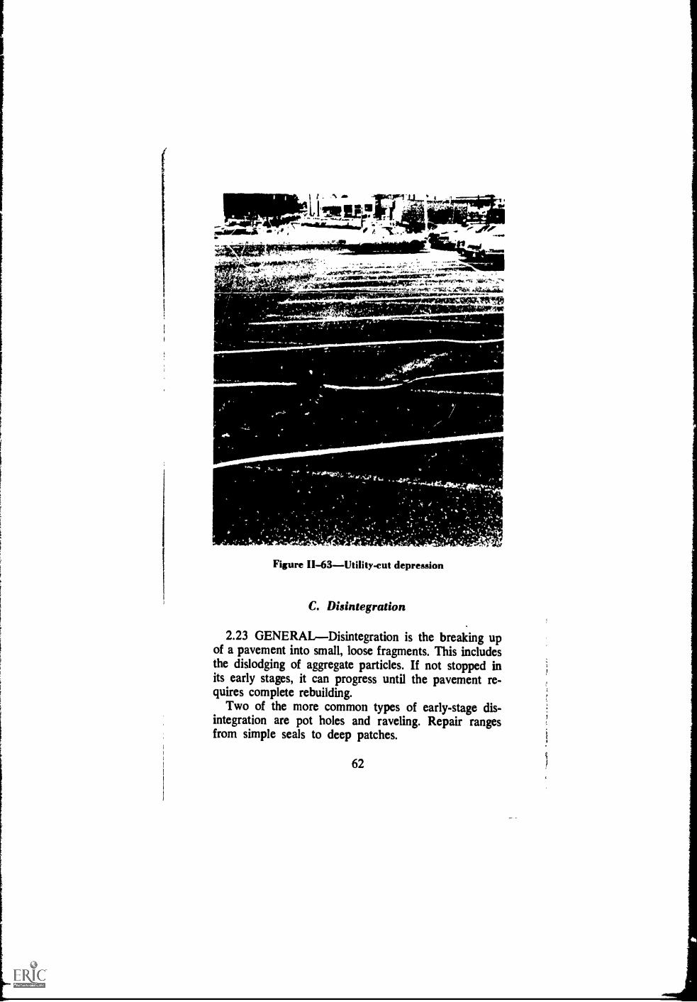
2.22 UTILITY CUT DEPRESSIONSDepressionsin the pavement that develop from a cut for utility in-stallation or repair, Figure 11-63.
(1) CauseThese depressions usually are causedby lack of adequate compaction of backfill.
(2) RepairSee Depressions (Article 2.20).
61
s_
Figure II-63--Utility-cut depression
C. Disintegration
2.23 GENERALDisintegration is the breaking upof a pavement into small, loose fragments. This includesthe dislodging of aggregate particles. If not stopped inits early stages, it can progress until the pavement re-quires complete rebuilding.
Two of the more common types of early-stage dis-integration are pot holes and raveling. Repair rangesfrom simple seals to deep patches.
62
The repair techniques recommended in this section are
not necessarily the only correct ways to do the job. They
are, however, proven methods that will give satisfactory
results.
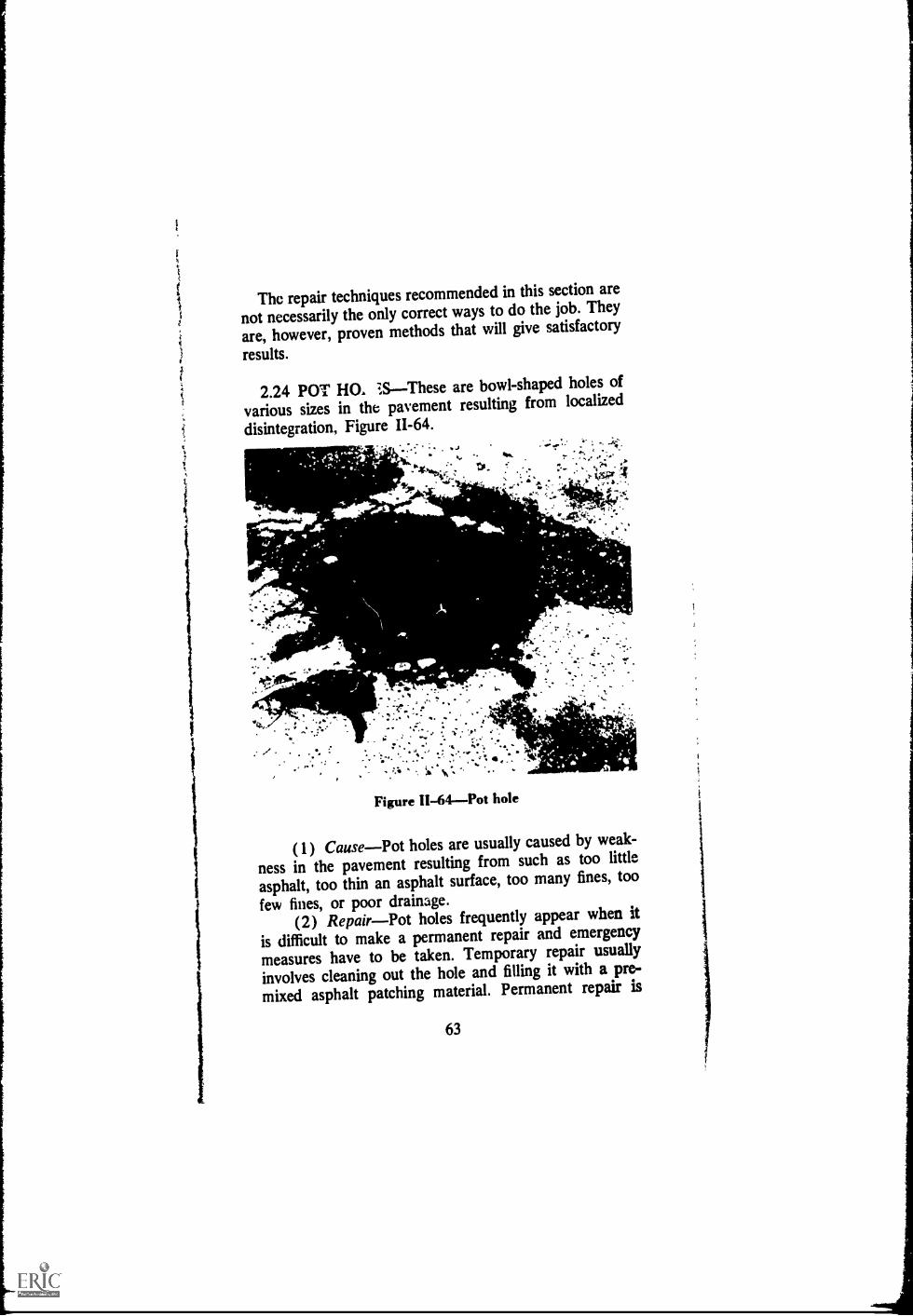
2.24 POT Ha 7SThese are bowl-shaped holes of
various sizes in the pavement resulting from localized
disintegration, Figure 11-64.J6.
, ;.*
to $,,,
4.,;-,s.,.
Figure 11-64--Pot hole
AIL
(1) CausePot holes are usually caused by weak-
ness in the pavement resulting from such as too little
asphalt, too thin an asphalt surface, too many fines, too
few fines, or poor drainage.(2) RepairPot holes frequently appear when it
is difficult to make a permanent repair and emergency
measures have to be taken. Temporary repair usually
involves cleaning out the hole and filling it with a pre-
mixed asphalt patching material. Permanent repair is
63
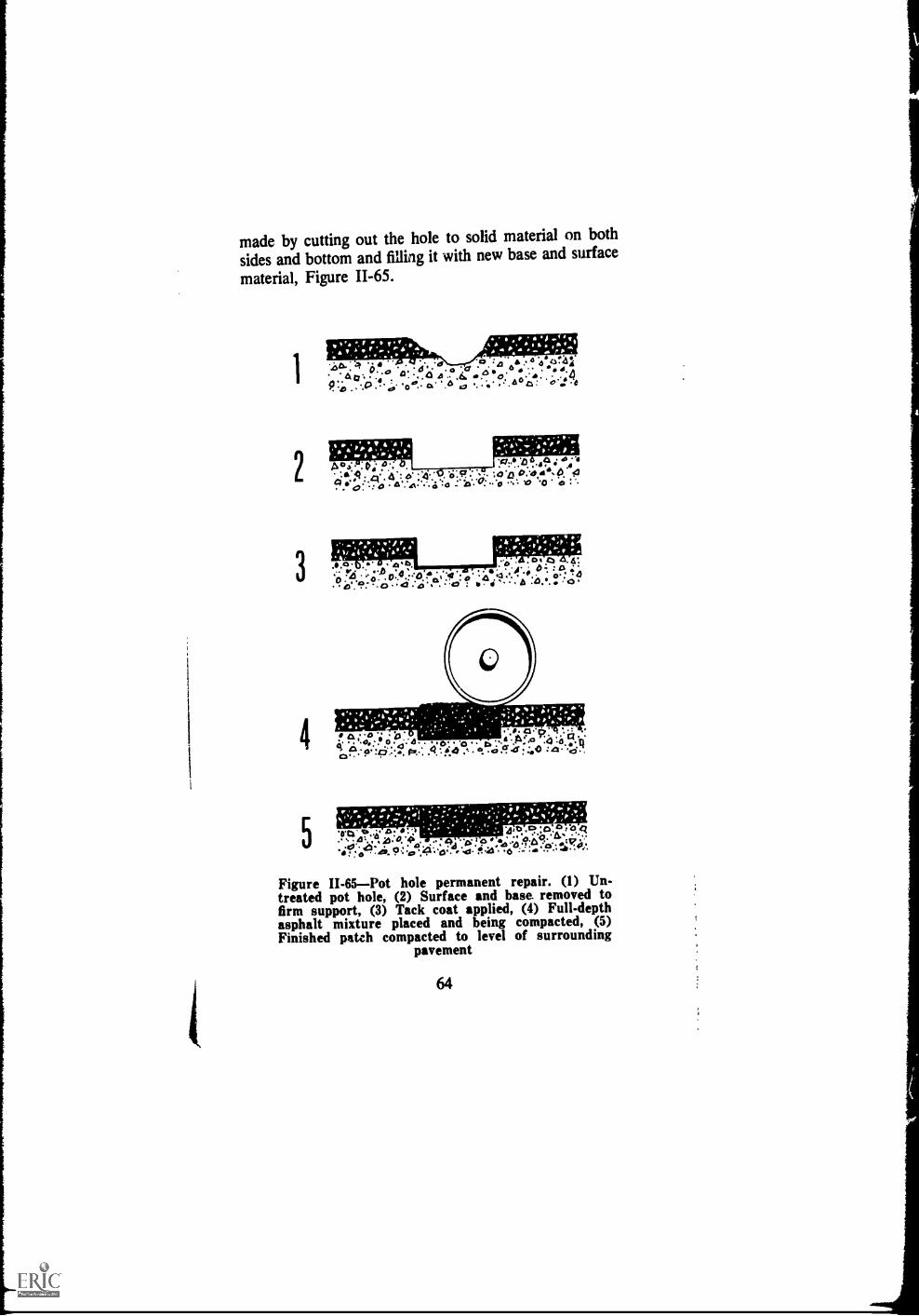
made by cutting out the hole to solid material on bothsides and bottom and filling it with new base and surface
material, Figure 11-65.
1
3
v , - ..4
..417A* .-15 GI ***. 6641'..e..14
.% by 4, :t I 4
o a:* .0,.43 'II
q 4 o 4 o 0.o.'so 4
Figure II-65Pot hole permanent repair. (1) Un-treated pot hole, (2) Surface and base. removed tofirm support, (3) Tack coat applied, (4) Full-depthasphalt mixture placed and being compacted, (5)Finished patch compacted to level of surrounding
pavement
64

Emergency Repair:
(a) Clean hole of loose material and as much water aspossible, Figure 11-66.
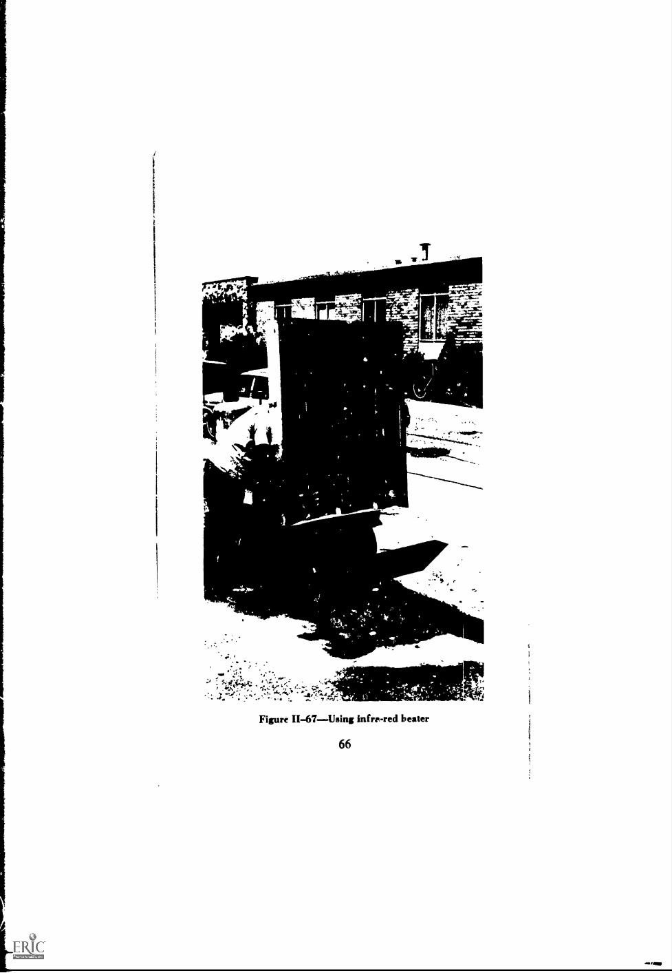
(b) Use infra-red heater to heat and soften asphalt sur-facing surrounding hole, Figure 11-67,
(c) Fill hole with asphalt emulsion stockpile mixtureand rake smooth, Figure 11-68.
(d) Compact with vibratory plate compactor or roller,
Figure 11-69.(e) Dry compacted patch with infra-red heater, Figure
11-70.
Permanent Repair: See Alligator CracksDeepPatch (Article 2.09).
.ftot- -5pfraJr"
.4I4 Ilt
ttit
i..-- ....A.-..
....c..:
Figure H-65--Cleaning hole of loose material
65
lit
1
,10
-.ter4. '
ao
r
"^ ;',44
i".1;5.
IIM:tr==..
,
ek;
Figure 11-67Using infrp-red beater
66
f

Prw-
avoftem.
441.4
Figure II-68--Filling hole with stockpile mixture
1.
114 IN
' oalPaX
Figure 11-69Comparting with vibratory p:.tecompactor
67
.44114

4
"1" ^ .4 7.
.J1t
Figure II-70Drying patch with infra-red htater
2.25 RAVELINGThis is the progressive separa-tion of aggregate particles in a pavement from the surfacedownward or from the edges inward, Figure 11-71. Usu-ally, the fine aggregate comes off first and leaves little"pock marks" on the pavement surface. As the erosioncontinues, larger and larger particles are broken free andthe pavement soon has the rough and jagged appearancetypical of surface erosion.
(1) CauseRaveling is caused by lack of compac-tion during construction, construction during wet or coldweather, dirty or disintegrating aggregate, too little as-phalt in the mix, or overheating of the asphalt mix.
(2) RerairRaveling surfaces, dry and weatheredsurfaces, and porous surfaces are conditions which usu-ally require a surface treatment. These treatments maybe looked upon either as corrective maintenance or aspreventive maintenance. In the former case they are
68

'1.
Figure H-71Raveling
used to correct an existing condition. In the latter casethey are used in an effort to prevent an anticipated con-dition from becoming a reality.
Emergency Repair:(a) Sweep the surface free of all dirt and loose aggregate
material.(b) Apply a fog seal (0.1 to 0.2 gallon per square yard,
depending upon the texture and porosity of the
69

pavement, of SS-lh or SS-Kh asphalt emulsion di-luted with equal parts of water). Cover aggregateis not required.
(c) Close to traffic until seal has cured.Permanent Repair:
(a) Same as (a), (b), and (c) for Emergency Repair.(b) Apply a surface treatment (slurry seal, sand seal,
aggregate seal, or plant-mixed surface treatment,depending on the condition of the surface and theamount of traffic). See Asphalt Surface Treatmentsand Asphalt Penetration Macadam, Manual SeriesNo. 13 (MS-13), The Asphalt Institute, for infor-mation on how to get a good surface treatment.
D. Skid Hazard
2.26 GENERALFew dry pavements are slippery.But there are a number of things that can make a pave-ment slippery when wet. One of the mo3t frequentcauses of slippery asphalt pavements is a thin film ofwater on a smooth surface. Another is a thick film ofwater which, at high speeds, causes the vehicle to leavethe pavement surface and skim over the water lilce anaquaplane. The smooth pavement condition usually isthe result of a film of asphalt on the surface, or polishedaggregate in the surface course. Slipperiness may alsodevelop from surface contamination, such as from oilspillage or certain types of clay. The object of skid hazardimprovement is to restore the pavement surface to a con-dition where water can flow around mmt of the surfaceaggregate particles, leaving contact between tire andaggregate. Treatment ranges from cleaning the surface ofcontamination to removal of excess asphalt and resurfac-ing to improve surface drainage.
2.27 BLEEDING OR FLUSHING ASPHALTBleeding, or flushing, is the upward movement of asphaltin an asphalt pavement resulting in the formation of afilm of asphalt on the surface, Figure 11-72.
70

'wan"
44
I
(I) CauseThe most common cause of bleeding,or fluz;hing, which usually occurs in hot weather, is toomuch asphalt in one or more of the pavement courses.This can reiiilt from too rich a plant mix, an improperlyconstructed seal coat, too heavy a prime or tack coat, orsolvent carrying asphalt to the surface. Also, overweighttraffic may cause added compression of a pavement, con-taining too much asphalt, forcing it to the surface.
(2) RepairIn many cases, bleeding can be cor-rected by repeated applications of hot sand, hot slagscreenings, or hot rock screenings to blot up the excessasphalt. Sometimes, when bleeding is light, a plant-mixedsurface treatment or an aggregate seal coat, using absorp-five aggregate, is the only treatment needed. Or a hotplant-mixed leveling course with a low asphalt contentcan be effective in absorbing the excess asphalt. With thistreatment, however, a new surface course is needed overthe leveling course to prevent raveling.
A pavement planing machine, such as a heater-planer,will remove the excess asphalt. Or in rare instances ofheavily over-asphalted surfaces, the surfaces should becompletely removed.
Repair with Hot Aggregate:(a) Apply 3/8-inch maximum size slag screenings, sand,
or rock screenings to the affected area. The aggre-gate should be heated to at least 300°F and spreadat the rate of 10 to 15 pounds per square yard.
(b) Immediately after spreading, roll with a rubber-tired roller.
(c) When the aggregate has cooled, broom off looseparticles.
(d) Repeat the process, if necessary.Repair with a Heater-Planer:
(a) Remove the asphalt film with a heater-planer, Fig-ure 11-73.
(b) Leave the surface as planed, or(c) Apply either a plant-mixed surface treatment or a
seal coat, Figure 11-74.
72

Figure II-73--Removing excess asphalt withheater-pls aer
Figure II-74Applying surfacetreatmcnt chips
y,
Se.V-
..1:
73
' -
1141"ey.
,Ai4!°11Pr'

2.28 POLISHED AGGREGATEThese are aggre-gate pal ticles in the surface of a pavement that havebeen polished smooth, Figure 11-75. This includes bothnaturally smooth uncrushed gravels and crushed rockthat wears down quickly under the action of traffic.
die
'NNW
Figure 11-75Polished aggregate in pavementsurface
(1) CauseSome aggregates, particularly sometypes of limestone, will become polished rather quicklyunder traffic. Others, such as some types of gravel arenaturally polished and if they are used in a pavementsurface without crushing they will he a skid hazard.These polished aggregates are quite slippery when wet.
(2) RepairThe only effective way to repair apavement with polished aggregates is to cover the sur-face with a skid resistant treatment. A hot plant-mixedsurface treatment, a sand seal, or an aggregate seal shouldbe applied. The aggregate must be hard and angular, suchas slag silica sand, or other proven non-polishing ma-terial.
74
Plant-mixed Surface Treatment:
(a) Apply a Het tack coat (0.05 to 0.15 gallon per
square yard of SS-1 or SS-lh asphalt emulsion di-
luted with equal parts of water), Figure 11-89.
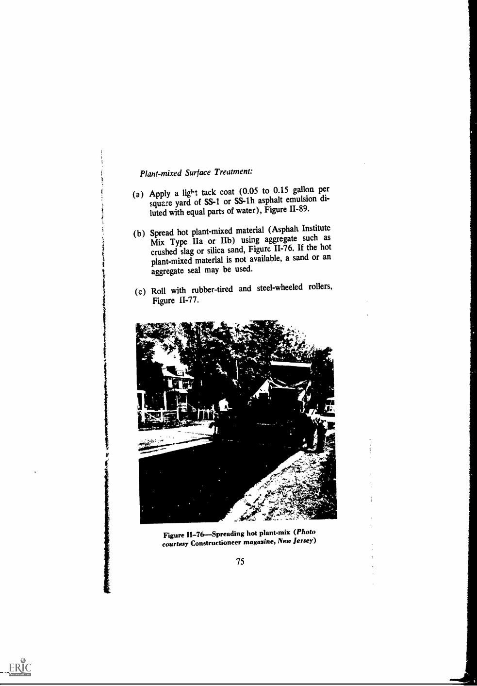
(b) Spread hot plant-mixed material (Asphalt Institute
Mix Type IIa or IIb) using aggregate such as
crushed slag or silica sand, Figure 11-76. If the hotplant-mixed material is not available, a sand or an
aggregate seal may be used.
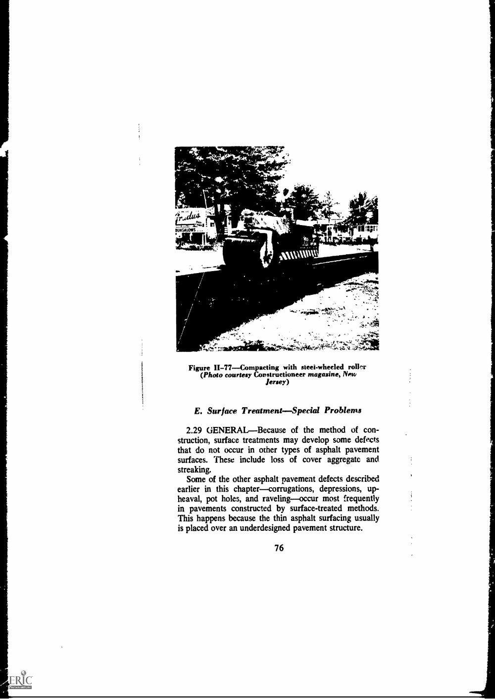
(c) Roll with rubber-tired and steel-wheeled rollers,
Figure 11-77.
0`.
Figure II-76--Spreading hot plant-mix (Photocourtesy Conatructioneer magazine, New Jersey)
75
--,r,a1, I. at,'..k ill,. .
04,. ; "t,4,l,.24,141.
iitimsnows . -" .12C.2111r!FAIIII MI6..
I ,v1:
-
calmwervt
-1 311;
..4.444%;L.44401
0.1
Figure 11-77Compacting with steel-wheeled roll,nr(Photo courtesy Constructioneer magazines New
Jersey)
E. Surface TreatmentSpecial Problems
2.29 GENERALBecause of the method of con-struction, surface treatments may develop some defectsthat do not occur in other types of asphalt pavementsurfaces. These include loss of cover aggregate andstreaking.
Some of the other asphalt pavement defects describedearlier in this chaptercorrugations, depressions, up-heaval, pot holes, and ravelingoccur most frequentlyin pavements constructed by surface-treated methods.This happens because the thin asphalt surfacing usuallyis placed over an underdesigned pavement structure.
76

2.30 LOSS OF COVER AGGREGATEThe whip-ping-off of aggregate under traffic fk om a surface-treated
pavement, leaving the asphalt, Figure 11-78.
Figure 1I-78Lo8 s of cover aggregate
(1) CauseSeveral things can cause the loss of
cover aggregate. If the aggregate is not spread immedi-
ately (within one minute) after the asphalt is appliedto the pavement surface the asphalt may have cooled
too much to hold it. If the aggregate is too dusty or too
wet when spread the asphalt may not be able to holdit under traffic. If the freshly-spread aggregate is not
rolled immedately after placing it may not become seated
in the asphalt sufficiently to hold under traffic. Or, if asteel-wheeled roller alone is used for compaction, aggre-gate may be lost from low spots that are bridged over by
the roller. Other reasons are: weather too cool when
77

treatment was arplied; fast traffic too soon on the newsurface treatment; and a surface which absorbs part ofthe asphalt leaving too little to hold the aggregate.
(2) RepairHot coarse sand, spreau over theaffected areas, may be used lo replace the lost aggregate.After spreading, it should be rolled immediately witha pneumatic-tired roller so that i+ will be seated intothe asphalt. If the aggregate only partially whipped-offan absorptive aggregate seal may be the most practicaltreatment.(a) On a hot day, spread coarse sand, heated to at least
300°F, over the area that has lost cover aggregate.(b) Follow immediately (before sand has a chance to
cool even a few degrees) with a pneumatic -ollerto seat the aggregate in the asphalt.
2.31 LONGITUDINAL STREAKINGAlternatinglean and heavy lines of asphalt running parallel to thecenterline of the roaci, Figure 11-79.
(1) Cause Several things can cause longitudinalstreaking:(a) Spray bar on the avhalt distributor not Ft at the
correct height for the spray fans to overlap properly.(b) Spray bar rising as load in distributor lightens.(c) Nozzle on spray bar not set at correct angle, not
all set at same angle, are the wrong size, differ insize, some plugged with cold asphalt, or have im-perfections.
(d) Wrong asphalt pump speed.(e) Too cold asphalt.(f) 1 oo low a pump pressure.
A single centerline streak may be caused by too littleasphalt or too cold as/Pali at the matching joint between
o applications.
(2) RepairAbout the only satisfactory repair forlongitudinal streaking is to plane off the streaked sur-
78

At-
.0111116-
,- ,,.4;.i... ...1..-.:-
, ...?,.-c-,4,4045 y , -
4,4.1. . .)...0....
...
... =1'.044* IA:- ,;.iii?-. .-74%
4. * - - ,. .t4
Figure H-79--Longitudinal streaking
face and apply a new surface treatment. It is much easier
to prevent longitudinal streaking than to correct -4. Care-ful adherence to the manufacturer's recommendations for
the asphalt distributor bere it is used and while it isbeing used will forestaN streaking. Asphalt Surface Treat-ments and Asphalt Penetration Macadam, Manual Series
No. 13 (MS-13), The Asphalt Institute, also recom-mends a number of checks to assure proper operation
of the asphalt distributor.
2.32 TRANSVERSE STREAKING Alternatinglean and heavy lines of asphalt running across the roadwhich may result in corrugations in the pavement surface.
(1) CauseTransverse streaking is caused by
79

spurts in the asphalt spray from the distributor Epraybar. These spurts may be produced by pulsation of theasphalt pump due to worn or loose parts, by improperpump speed, or by a miss in the motor.
(2) RepairSee Corrugations (Article 2.19), andLongitudinal Streaking (Article 2.31).
80

Chapter inASPHALT IN THE MAINTENANCE OF
PORTLAND CEMENT CONCRETEPAVEMENTS
3.01 ASPHALT FOR PCC MAINTENANCEAs-phalt has an important role in the maintenance of port-land cement concrete pavements. It seals joints andcracks. It fills cavities and raises sunken slabs. It renewsdisintegrating pavements and covers slick surfaces. Morespecifically, asphalt and asphalt mixtures are used in themaintenance of portland cement concrete pavements to:
Restore design grade and surface smoothness.Repair and retard spalling, scaling, and other
deterioration.Repair badly broken areas.Improve skid resistance.Frotect and preset Ye the orinal jothtKeep foreign material out of joints and cracks.Keep ..vter out of the base.Prevent pumping and stabilize the subgrade.Stop Fiab rocking.Prevent damage from frost action.Stop disintegration from use of de-icing chemicals.
Asphalt, then, can do an excellent job in repairingmany defects in portland cement concrete pavements, butonly if used correctly. The techniques discussed in thischapter are not the only correct ones. But they are meth-ods that have been proven satisfactory by use.
For discussions of patching mixtures, tack coats, plac-ing patching mixtures, and compacting patches see Chap-ter II.
3.02 JOINT AND CRACK SEAL1NGJoint andcrack sealing is done for several reasons: it prevents sur-
81

face water seepage, it protects joint fillers, and it keepsout foreign matter. At one time penetration-grade as-phalt, alone or with filler added, was the sealing materialmost commonly used. lt still is used in many places. Butin recent years, rubber-asphalt compounds have gainedfavor because, among other advantages, they have lesstendency to become brittle in cold weather and to softenand track under traffic in hot weather. Table III-1 listsseveral types of rubber-asphalt joint and crack sealers.
Table III-1
ASPHALTIC JOINT AND CRACK SEALERSFOR PORTLAND CEMENT CONCRETE PAVEMENTS
Material Type
Specification
Federal ASTM AASHO
Rubber-asphalt Cold-applied SS-S-156 D 1850
Rubber-a:ph:14 Cold-crpplied mastic SS-S-1596 D 1850
Rubber-asphalt Hot-applied SS-S-164 D 1190 M 173
The equipment used for sealing joints and cracksvaries from small hand-pouring pots to truck- or trailer-mounted pressure applicators. Hand-pouring pots nor-mally are refilled from a central heating kettle. Whenheating kettles are used they should be the double-jacketed, oil-bath type to avoid damage of the sealerby overheating. With rubber-asphalt compounds the heat-ing kettles must be of this type.
Hand pouting-pots are used with heating kettles. Toprevent overfilling of the joint or crack a squeegee shouldbe used. A squeegee of the type shown in Figure III-1,used properly, will assure a neat job.
Truck- or trailer-mounted pressure applicators willhandle either hot or cold applied sealing materials. Fig-ure 111-2. They have control valves and are equippedwith nozzles of the size and shape needed to convey thesealing material into the opening. This type of equipment
82

4
,,
Figure 11I-1Squeegee
;'ll
is both convenient and rapid. It also avoids excessivespilling of the sealing material on the pavement surface.
Before any sealer is used joints and cracks must becleaned out. Power routers, air compressors and sandblasters speed up and make the job much easier. The aircompressor should be equipped with nozzles of the sizeand shape needed to direct the air stream into the crevicebeing sealed.
Just enough sealing material should be placed in thejoint or crack to fill it. When hot sealer is used to filldeep crevices the material may shrink somewhat uponcooling. Enough additional sealer should be added tofill the opening flush with the surface. On airfield pave-ments used by jet planes, special sealing material shouldbe used.
Frequently, pavements must be kept open to one-lane traffic while sealing work goes on. It is good prac-tice for workmen to begin filling operations at the cen-terline and back towards the edge of the pavement. Thiswill avoid backing into the stream of traffic.
83

If the pavement is to be opened to traffic immediatelyafter sealing, the material must be protected againstpick-up by tires. This can be done by dusting the jointsand cracks with fine sand, mineral dust, hardwood saw-dust, or similar materials. C-1d-applied sealers may becovered with paper tape.
Figure III-2Trailer-mounted seal applicator (Photocourtesy Virginia Department of Highways)
3.03 UNDERSEALINGCavities may occur be-neath a portland cement concrete pavement as a resultof pumping of the slabs or settlement of the subgrade.When this happens they should be filled to restore the
84

pavement's support and prevent further erosion. Under-sealing asphalt is used for this purpose. It fills thecavities, raises sunken slabs, and forms a waterprooflayer that prevents fine material from pumping out again.
The process is called undersealing. It is fully described in
The Asphalt Institute's publication Specifications forUndersea ling Portland Cement Concrete Pavements withAsphalt, Specification Series No. 6 (SS-6).
CAUTIONOnly asphalt especially preparedfor undersealing should be used.
3.04 OVERLAYSFor many types of defect inportland cement concrete pavement an asphalt overlayis the most effective and most economical treatment.Distorted pavements often can be restored to smoothness
with asphalt overlays. Disintegrating pavements can besalvaged and strengthened with them. Slippery pave-ments can be made skid resistant with the proper asphaltoverlays. Generally, this type of correction is consideredconstruction rather than maintenance. Overlays can beused for short stretches as a maintenance operation,
however.Overlays are discussed in The Asphalt Institute publi-
cations, A Short, Practical Guide to the Design of As-phalt Overlays, Information Series No. 139 (IS-139),and Thickness DesignAsphalt Pavement Structures forHighways and Streets, Manual series No. 1 (MS-I ).
A. Joints and Cracks
3.05 GENERALRelatively large volume changesare produced in portland cement concrete by variationsin temperature. Because of this all such pavements crack;it is a natural property of the material. To make theconcrete crack in neat, straight lines pcc pavements havejoints at frequent intervals.
85

Joints are either formed the full depth of the slabor grooved to a depth of one-sixth to one-quarter of itsthickness. Full-depth joints are junctions between slabsto permit expansion, to control cracking, or to meetconstruction requirements. Grooved joints are formedor cut to force cracking along the weakened plane.Depending upon their function, they are called expansionjoints, contraction joints, or construction joints. Theymay run in a transverse, longitudinal, or diagonal direc-tion.
Another type of joint is the one between the pcc slaband the shoulder. It is a longitudinal construction jointcalled a shoulder joint. See Figure 111-3. Also, there areother types of joints which have special purposes. Theyare maintained in the same way as the main types.
All joints and cracks must be kept sealed with someadhesive material to prevent damage to the pavementfrom water and foreign matter. Asphalt, with or withoutan additive such as rubber, is used almost universally asa joint and crack sealing material.
The methods used for sealing joints and cracks areessentially the same. Both consist of cleaning out theupper portion of the crevices and filling them with asealing material. To be effective, the sealing materialmust stick to the sides of the opening. For this reasonany material which will prevent a good bond must becleaned out. If sand, gravel, dust, or other foreign mat-ters have accumulated in the opening they must be re-moved. They may cause the edges to spall when thejoint or crack closes unde ,. expansion of the slab in hotweather. Old sealing material which has become hard-ened should also be removed.
If the job is smail, the clean-out operations may beperformed by hand. Stiff-fiber or steel-bristle brooms andbars with chisel ends shaped to fit the joint opening aretools that can be used. For larger jobs, the work canbe done more rapidly with power-driven rotary cutters,power pavement saws, air compressors, or similarequipment.
86

Special treatment may be necessary where the jointor crack is very narrow or has badly spalled edges.When such conditions are encountered, a recess to re-ceive the sealing material may be grooved out with apower-driven pa ement saw or rotary cutter.
Figure III-3Shoulder joint
87

3.06 RESEALING JOINTSJoints reed periodicmaintenance. The joint seal may need replacing forany of a number of reasons, among them, the wrong typeof material may have been used; the seal may havebeen overheated; the joint may not have been cleanedproperly before sealing.
In all cases, joints needing resealing should be plowedout to a depth of 1 inch. Before the new seal is appliedall surfaces in and around the joints should be clean anddry, with no bits of filler or old seal clinging to thesides. Sponge rubber, plastic, or tape should be insertedinto the groove to provide a non-adhesive lower face forthe seal.
The following method of cleantng and resealing jointshas been found satisfactory.
(a) Plow out old seal (and filler if present) to a depthof 1 inch, Figure 111-4.
(b) Use a joint-cleaning machine to clean the verticalfaces of the joint and to remove foreign materialsfrom the pavement surface at least 1 inch on eachside of the joint, Figure 111-5.
(c) Sandblast vertical faces of the joint and the pave-ment surface at least 1 inch on each side of thejoint. Use hand tools to remove any traces of CAseal that might be left.
(d) Blow out joints with compressed air at a pressureof at least 90 psi with 150 cubic feet per minuteof air at the nozzle, Figure 111-6.
(e) Insert sponge rubber, plastic, or tape to the bottomof the groove.
(f) Seal in one pour, Figure 111-7. (The outer endsof transverse joints must be dammed to preventsealing material from running out on to theshoulder.'
88
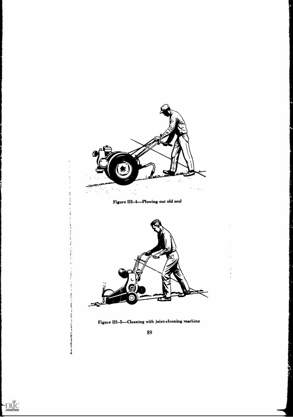
. . -
T'
Figure III-4Plowing out old seal
Figure III-5--Cleaning with joint-cleaning machine
89s
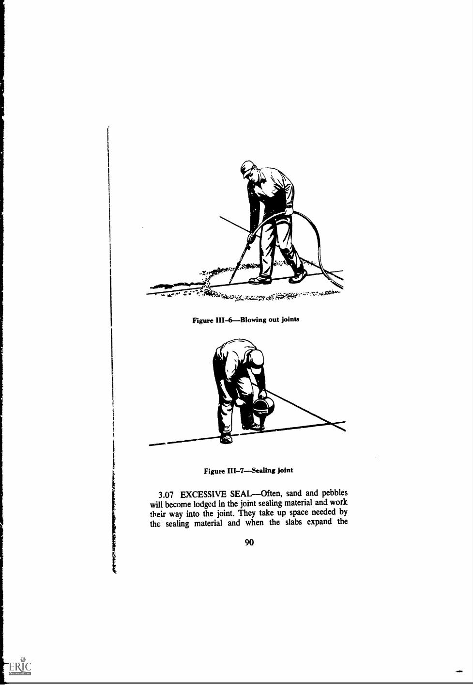
t
sIOS.NOIO.
Figure III-6--Blowing out joints
zawr.1.110..w......,Vw.L........---
Figure III-7--Sealing joint
3.07 EXCESSIVE SEALOften, sand and pebbleswill become lodged in the joint sealing material and worktheir way into the joint. They take up space needed bythe sealing material and when the slabs expand the
90

seal pushes up from the joint and forms a bump. Some-times there is enough of this foreign matter in the jointto cause spalling ol the slabs. When this happens theseal should be plowed out and the joint resealed (seeResealing Joints, above). But in many cases the excesscan be removed by cutting it off with a heated square-point spade or a power-driven rotary cutter. When alarge amount of extruded sealing material is to betrimmed, a special blade with plow handles, pulled by atruck or a winch may do the job effectively.
3.08 SEALING CRACKSCracks in portland ce-ment concrete pavements are defined as "approximatelyvertical random cleavage due to natural causes or trafficaction." Included under this definition are transversecracks, longitudinal cracks, diagonal cracks, cornercracks, and restraint cracks.
If a crack is not wide enough to receive the sealingma#trial with ease. sealing it should not even be tried.Wide cracks should be thoroughly cleaned before sealing.
3.09 CORNER CRACKS These are diagonalcracks forming a triangle with a longitudinal edge orjoint and a transverse joint or crack, Figure 111-8.
(1) CauseCorner cracks can be caused bytraffic loads on unsupported corners or curled or warpedslab. They may also be caused by loads over weakspot., in the subgrade under the slabs.
(2) RepairRemove the broken corner and patchwith dense-graded asphalt concrete.(a) Remove the broken corner.(b) Leva the subbase, if required, and prime it as de-
tailzd in Specification P-1, Asphalt Priming ofGranular Type Base Courses, Asphalt SurfaceTreatments and Asphalt Penetration Macadam,Manual Series No. 13 (MS-11), The Asphalt In-stitute.
(c) Apply a tack coat to the sides of the slab.
91
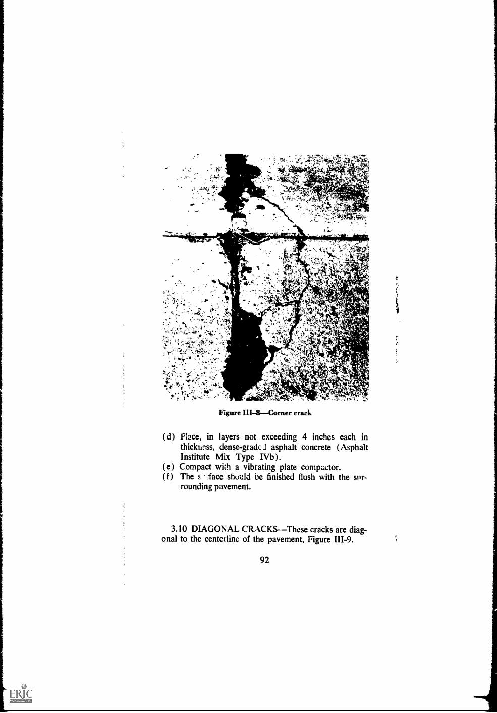
Figure IH-8Corner crack
(d) Place, in layers not exceeding 4 inches each inthicktetss, dense-gradc1 asphalt concrete (AsphaltInstitute Mix Type IVb ).
(e) Compact with a vibrating plate compactor.(f ) The i %lace should be finished flush with the stn.-
rounding pavement.
3.10 DIAGONAL CRACKSThese cracks are diag-onal to the centerline of the pavement, Figure 111-9.
92
t
:

Figure 111-9Diagonal crack
(1) CauseDiagonal cracks generally are caused
by traffic loads on unsupported slab ends. The founda-
tion settles or the slab curls, then subgrade soil pumps
out, mostly along the edge. This results in a diagonal
crack.
(2) RepairRepair for this type of crack consists
of filling the void beneath the pavement and cleaning
and sealing the crack.
(a) Sandblast the vertical faces of the crack to a depth
of at least 1 inch and the pavement surface at least
1 inch to each side of the crack.(b) Blow out the crack with compressed air.
(c) Half fill the crack with a rubber-asphalt compound
selected from Table III-1.
(d) Underseal the slab using the procedure detailed inSpecifications for Undersealing Portland CementConcrete Pavements with Asphalt, Specification
Series No. 6 (SS-6), The Asphalt Institutt...
(e) Finish filling the crack with the rubber-asphalt
compound.
93

I
3.11 LONGITUDINAL CRACKSThese cracks areapproximately parallel to the center line of the pavement,Figure III-10.
(1) CauseSome causes of longitudinal crackingare shrinkage of the concrete (if the pavement is toowide and has no longitudinal joint), expansive subbaseor subgrade, warping stresses in combination with loads,too shallow centerline joints not :Awed early enough,loss of support from edge pumping.
(2) RepairSee repair procedure for TransverseCracks (Article 3.13).
Figure III-10Longitudinal crack
94

3.12 RESTRAINT CRACKS These are crackswhich develop near (within 3 feet or less) the outsideedges of a pcc pavement and progress in an irregularpath toward the longitudinal joint, Figure III-11.
(1) CauseRestraint cracks are caused by for-eign matter, such as hard gravel, becoming lodged deepin a transverse joint and restraining the slabs fromexpanding.
*
=
0.009
ir*OP:
11.
Figure III-11Restraint crack
95

(2) RepairThe blocked transverse joint shouldbe plowed out and resealed. The restraint cracks shouldbe cleaned and sealed if they are wide enough to re-quire sealing. The following references to cracks do notapply if the cracks are not to be sealed.(a) Plow out the old sealer and foreign matter in the
transverse joint to the depth rquired to removeall contamination.
(b) Use a joint-cleaning machine to clean the verticalfaces of the joint and to remove foreign materialsfrom the pavement surface at least 1 inch on eachside of the joint.
(c) Sandblast the vertical faces of the joint and crackand the pavement surface at least 1 inch on eachside of the joint and crack.
(d) Blow out the joint and cracks with compressed airat a pressure of at least 90 psi, with 150 cubic feetper minute of air at the nozzle.
(e) Seal the joint and cracks in two pours with a rubber-asphalt compound selected from Table III-1.
3.13 TRANSVERSE CRACKS These cracks areapproximately at right angles to the centerline of thepavement, Figure 111-12.
(1) CauseSome major causes of transversecracks are overloads, repeated bending of pumping slabs,failure of soft foundations, "frozen" joints, lack of joints,too shallow joints, and shrinkage of the concrete.
(2) Repair--Clean the cracks of all loose matterand fill with a rubber asphalt sealer. If the crack iscaused by pumping, the void beneath the pavementmust be filled (see Specifications for Undersea ling Port-land Cement Concrete Pavements with Asphalt, Specifi-cation Series No. 6 (SS-6), The Asphalt Institute).(a) Sandblast the vertical faces of the cracks to a depth
of at least 1 inch and the pavement surface at least1 inch to each side of the crack.
(b) Blow out the crack with compressed air.(c) Fill the crack with a rubber-asphalt compound se-
lected from Table III-1.
96

to P
Figure III-12Transver5e cracks
B. Distortion
3.14 GENERALDistortion is any change of thepavement surface from its original shape. Faulting is oneof the most predominant types of pcc pavemeht distor-tion. Pumping cannot be classified as distortion but itresults in faulting or sunken slabs. Therefore, it is in-
97

cluded in this section. Major causes of distortion areexpansive soils, frost susceptible soils, and foundationsettlement.
If not too extensive, some forms of distortion (suchas from settlement) can be remedied by raising the slabto bring it again to the original grade. One method ofdoing this is by pumping a high softening point under-sealing asphalt under the slab. Sometimes the pavementsurface is so badly distorted that 'an asphalt concreteoverlay is the most economical repair.
3.15 FAULTA fault is a difference in elevation oftwo slabs at a joint or a crack, Figure 111-13.
( 1 ) CauseFaults usually develop from inade-quate load transfer between slabs along with consolida-tion or shrinkage in volume of courses underlying theslabs. They may be caused also by pumping out of thefoundation material.
(2) RepairIf possible, faulted slabs should bebrought back to the original grade with a high softeningpoint undersealing asphalt cement underseal, raising thelow side in the process. The joint or crack should bepartially filled with joint scaler before undersealing be-gins. In some cases, it may be necessary to place wedg-type patches for leveling and then place an asphalt over-lay.(a) Plow out old scaler, if present, to a depth of 1 inch.(b) If needed, use a joint cleaning machine to clean
the vertical faces of the joint or crack and to re-move foreign materials from the pavement surfaceat least 1 inch on each side of the joint or crack.
(c) Sandblast vertical faces of the joint or crack andthe pavement surface at least 1 inch on each sideof the joint or crack. Use hand tools tc remove anytraces of old sealer thaL might be left.
(d) Blow out the joint or crack with compressed air ata pressure of at least 90 psi, with 150 cubic feetper minute of air at the nozzle.
(e) Half-fill the joint or crack with a rubber-asphaltcompound selected from Table III-1.
98
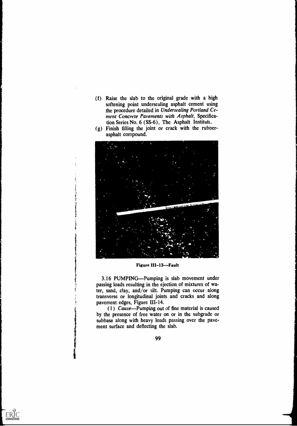
(f) Raise the slab to the original grade with a highsoftening point undersealing asphalt cement usingthe procedure detailed in Undersea ling Portland Ce-ment Concrete Pavements with Asphalt, Specifica-tion Series No. 6 (SS-6), The Asphalt Institute.
(g) Finish filling the joint or crack with the rubber-asphalt compound.
. ..........".-.Zr,,,,A011.
Figure III-13Fault
3.16 PUMPINGPumping is slab movement underpassing loads resulting in the ejection of mixtures of wa-ter, sand, clay, and/or silt. Pumping can occur alongtransverse or longitudinal joints and cracks and alongpavement edges, Figure 111-14.
(1) CausePumping out of fine material is causedby the presence of free water on or in the subgrade orsubbase along with heavy loads passing over the pave-ment surface and deflecting the slab.
99

(2) Repair The voids beneath the pavementshould be filled with a high softening point undersealingasphalt. This will also waterproof the subgrade andsubbase.(a) Use the procedure for resealing joints detailed in
Article 3.06, above.(b) Use the procedure detailed in Specifications for
Undersealing Portland Cement Concrete Pavementswith Asphalt, Specification Series No. 6 (SS-6), TheAsphalt Institute.
,
11' 121
411.0/ 1,
4" %
-;
1,1
o'L ,".-11,
4re
Figure III-14Pumping
100
41 IIt,
;411

C. Disintegration3.17 GENERALDisintegration is the breaking up
of a pavement into small, loose fragments. This includesthe dislodging of aggregate particles. If not stopped inits early stages, it can progress until the pavement re-quires complete rebuilding.
Common types of disintegration in portland cementconcrete pavements that can be repaired with asphaltare blow-ups, spalling, and scaling. Treatment rangesfrom skin patches to complete overlays,
3.18 BLOW-UPA blow-up is the localized bucklingor shattering of a rigid type pavement, occurring usuallyat a transverse crack or joint, Figure 111-15 and 111-16.
(1) CauseMost blow-ups are caused by exces-sive expansion of the slabs during het weather. Thepressure builds up until the slabs cannot resist it anylonger and they either buckle or shatter, crumbling alongthe transverse joint or crack.
(2) RepairAsphalt concrete may be used foremergency or permanent repair of the damaged slab.The slab should be cut, preferably with a power saw, to
remove the affected area. Dense-graded asphalt concreteis then used to restore the pavement.(a) Remove the damaged portion of the slab by sawing
a straight, neat cut with a pavement saw.(b) Level the subbase, if required, and prime it as
detailed in Specification P-I, Asphalt Priming ofGranular Type Base Courses, Asphalt SurfaceTreatments and Asphalt Penetration Macadam,Manual Series No. 13 (MS-13), The Asphalt Insti-tute.
(c) Apply tack coat to the sides of the slab.(d) Place and compact dense-graded asphalt concrete
(Asphalt Institute Mix Type IVb), in layers notexceeding 4 inches each. If the area is not largeenough for a full sized roller, mechanical rammersand/or vibrating plate compactors should be used.
(e) The surface should be finished flush with the sur-rounding pavement.
101
os
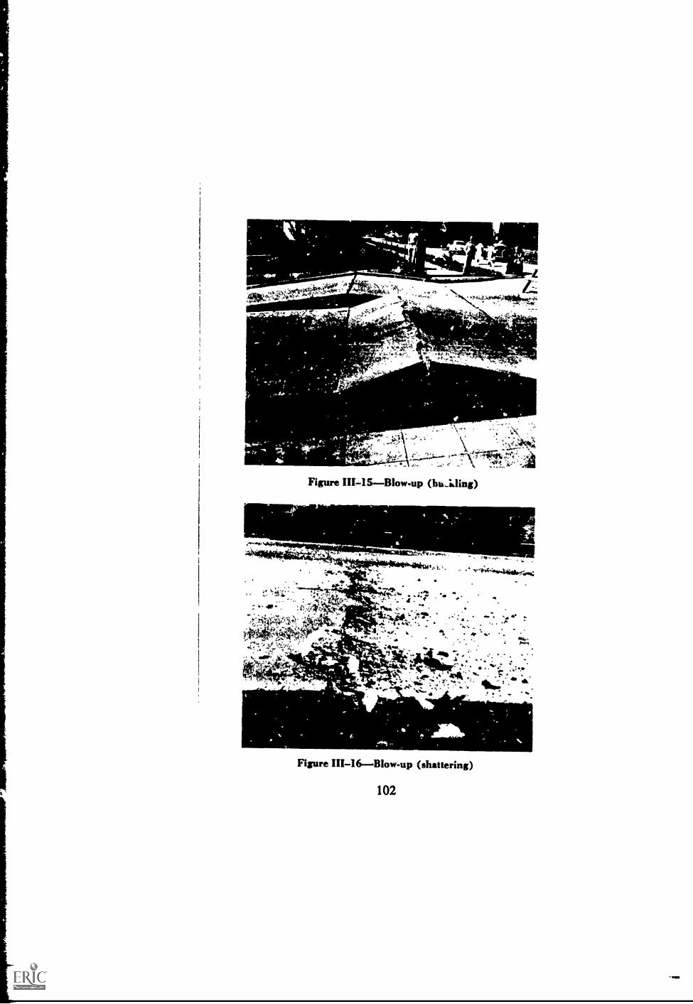
Figure III-15Blow-up (hu..kling)
6gegadM1111.6.
4:10010144raigt.1
4.0.--03
.=4
t 4 y.4.
p, --**44140iide;ais:
A.. 6.
.
4 A "- *kk :
44.,acik 46. 4* Albw " *NM
AffiiML
Figure III-16Blow-up (shattering)
102
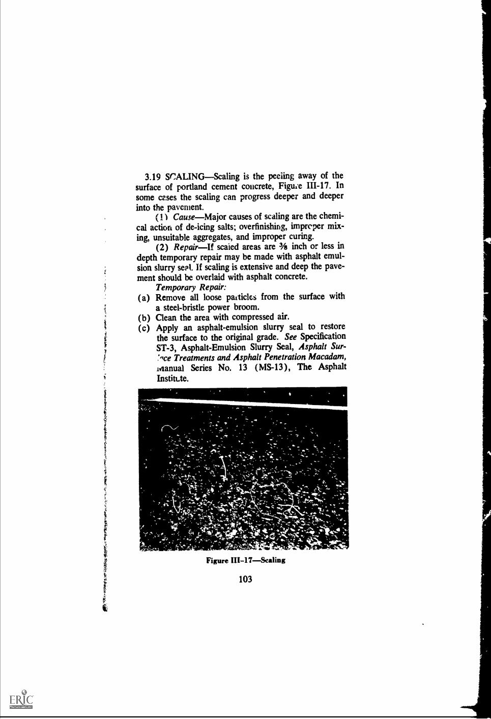
3.19 SCALINGScaling is the peeiing away of thesurface of portland cement concrete, Figwe 111-17. Insome cases the scaling can progress deeper and deeperinto the pavement.
(1) CauseMajor causes of scaling are the chemi-cal action of de-icing salts; overfinishing, impreper mix-ing, unsuitable aggregates, and improper curing.
(2) RepairIf scaied areas are 3A inch or less indepth temporary repair may be made with asphalt emul-sion slurry seal. If scaling is extensive and deep the pave-ment should be overlaid with asphalt concrete.
Temporary Repair:(a) Remove all loose paiticles from the surface with
a steel-bristle power broom.(b) Clean the area with compressed air.(c) Apply an asphalt-emulsion slurry seal to restore
the surface to the original grade. See SpecificationST-3, Asphalt-Emulsion Slurry Seal, Asphalt Sur--,ce Treatments and Asphalt Penetration Macadam,
idanual Series No. 13 (MS-13), The AsphaltInstitUe.
Mk
&mom&
416.4.11111 _
Figure III-17Sealing
103

3.20 SPALLINGThe breaking or chipping of thepavement at the joints, cracks, or edges is classified asspalling. Usually tin resulting fragments have featheredges, Figure 111-18.
(1) CauseSpalling can be caused by a numberof different .things. Some of the major causes are hardpieces of gravel becoming lodged in a joint or crack;improperly installed load transfer ,devices; improperforming and sawir of joints; and weak mortar.
Figure 1111-18--Spalling
104

(2) RepairAsphalt mixtures should be used forrepair of spalling.(a) Chip out the spalled area to sound material, squar-
ing the edges and making the sides as nearly vertical
as practical.(b) Blow out the area with compressed air.
(e) Apply a light tack coat of SS-1 or SS-k asphaltemulsion.
(d) Fill the hole with a dense-graded asphalt concretesimilar to Asphalt Institute Mix Type IVb. Placeenough mix in the hole to ensure its being flushwith the surrounding pavement after it is com-pacted.
(e ) Compact with a vibrating plate compactor.
D. Skid Hazard
3.21 GENERALA number of things can make apavement slippery when wet. A major cause of slipperyportland cement concrete pavements is polished aggre-gates in the surface. The aggregate particles may besmooth, uncrushed gravel or they may be the type thatpolishes under traffic. Slipperiness also may developfrom surface contamination. See discussion of slipperypavements, Article 2.26.
3.22 POLISHED AGGREGATEThese are aggre-gate particles in the surface of a pavement that ha vebeen polished smooth, Figure 111-19. This includes bothnaturally smooth uncrushed gravels and crushed rockthat wears down quickly under the action of traffic.
(1) CauseSome aggregates will become polishedquickly under traffic. Others, st;-h as sorrm types of :gavel
are naturally ponshedif these axe k:sed in a pave-ment surface without crushing they will be a skid hz.7.ard.These polished aggregates are extremely slippery when
wet.
105

(2) RepairThe most effective and economicalway to repair a pavement with pelished aggregates is tocover the surface with a skid resistant treatment. To re-duce the probability of reflection cracking the overlayshould be at least 3 inches thick.(a) Apply a light tack coat (0.05 to 0.15 gallon per
square yard of asphalt emulsion diluted with equalparts of water).
(b) Spread a course of asphalt plant mix using sharp,angular, non-polishing aggregate.
(c) Roll with rubber-tired and steel-wheeled rollers.
Figure !II-19Po1i.hed aggregate in pavementsurface
106

Chapter IV
SELECTION OF ASPHALT ANDASPHALT MIXTURES
4.01 ASPHALT FOR MAINTENANCE Thischapter identifies the principal types of asphalt and as-phalt mixtures used in maintenance work and the prop-erties which are considered desirable in each case.
Asphalt is refined from crude oil and is a product ofthe petroleum industry. At ordinary temperatures, be-low approximately 100°F, it is solid or semi-solid. Tobe used in maintenance operations, then, it must bemade liquid enough to coat the aggregate. This is ac-complished in three different ways: (1) by heating, asin a heating kettle or storage tank; (2) by dissolving ina petroleum solvent ' (cutbacks); (3) by combinationwith water (emulsion). See Table IV-1 for the variousgrades recommended for use in pavement maintenance.For a more detailed treatment of asphalt and its uses,refer to introduction to Asphalt, Manual Series No. 5(MS-5), and Specifications for Asphalt Cements andLiquid Asphalt, Specification Series No. 2 (SS-2), TheAsphalt Institate.
4.02 ASPHALT CEMENTSAsphalt cement is thebasic material of the asphalt family. It is a semisolidmaterial that comes in five grades. They are used inmaking hot mixes, for penetration surface treatmentsand macadams, for seal coats, and for filling certain typesof cracks. Asphalt cements are classiPcil by a carefully-controlled test in whim a standard size weighted needlepenetrates a sample ot asplIalt at a specified tempera-ture. The distance the needle penetrates into the asphaltin the specified time determines the grade. Thus, if at77'F, the needle, under a weight of 100 grams, pene-trates 90 tenths of a millimeter in 5 seconds, the asphalt
107

Tab
le IV
-1R
EC
OM
ME
ND
ED
US
ES
OF
AS
PH
ALT
IN P
AV
EM
EN
T M
AIN
TE
NA
NC
E
TY
PE
OF
CO
NS
TR
UC
TIO
N
. e u c o . .... e ex
PA
VIN
GA
SP
HA
LTS
LIQ
UID
AS
PH
ALT
S
0 2
R .
:-.4
8 c.4
Rap
id C
urin
g(R
C)
Med
ium
Cur
ing
(MC
)S
low
Cur
ing
(SC
)
1
Em
ulsi
fied
Ani
onic
Cat
ioni
c
A'
XI
coes
e ese r.
.R c4
8 co§ en
e r.ts
;c4
8 co0 es
a ocC
t; 4.
1
cmC
t.; 4
1 *. 'a
..a tn5 as
ul ectii
V v
iI
Zei
AS
PH
ALT
CO
NC
RE
TE
AN
D P
LAN
TM
IX,
HO
T L
AID
Hig
hway
s
Airp
orts
.... .
....
...
....
....
....
. .. .
.....
....
Par
king
Are
as.
....
....
......
.....
Driv
eway
s
SS
-1x
xx
MS
-11
xx
MS
-4x
x
MS
-4x
xP
LAN
T M
IX, C
OLD
LA
IDG
rade
d A
ggre
gate
....
......
.... .
......
......
SS
-1x
xR
OA
D M
IXO
pen-
grad
ed A
ggre
gate
..
......
....
.M
S-1
4x
xx
xx
xD
ense
-gra
ded
Agg
rega
teM
S-1
4x
xx
xx
xx
Cle
an S
and
MS
-14
xx
xx
xx x
San
dy S
oil
MS
-14
xx
xx
xx
xx

i
PE
NE
TR
AT
ION
MA
CA
DA
MLa
rge
Voi
ds .
MS
-13
xX
X
Sm
all V
oids
MS
-13
xx
x
SU
RF
AC
E T
RE
AT
ME
NT
SS
ingl
e, M
ultip
le a
nd A
ggre
gate
Sea
l
San
d S
eal
MS
-13
xx
X X
XX
Xx
xx
MS
-13
X X
xx
x
Slu
rry
Sea
l
Fog
Sea
l
Prim
e C
oat,
open
sur
face
s
Prim
e C
oat,
tight
sur
face
s.
+T
ack
Coa
t0 V
DD
ust L
ayin
g
MS
-13
MS
-13
xlxl
MS
-13
x
MS
-13
xx
r
x
Kx
MS
-13
xx
x 1
x1x
xlxl
MS
-13
A\ c
x
PA
TC
HIN
G M
IXIm
med
iate
Use
Sto
ck P
ile
SS
-1
SS
-1
xx
xlxl
CR
AC
K F
ILLI
NG
EX
PA
NS
ION
JO
INT
S
UN
DE
RS
EA
LIN
G P
CC
.....
.....
.. ...
.... .
......
.....
...
MS
-4x
rix
Xx
xK
2 X
2 X
MS
-4B
low
n as
phal
ts, m
iner
al-f
illed
asp
halt
cem
ents
,an
d pr
efo:
med
join
t
lx2
x2.
com
posi
tions
SS
-6B
low
n as
phal
ts
In n
orth
ern
woo
s w
here
rat
e of
cur
ing
is s
lo ..
. er,
a s
hift
from
MC
toR
C o
r fr
om S
C to
MC
may
be
desi
rabl
e. F
or v
ery
war
m c
limat
es, a
shift
to n
ext h
eavi
er g
rade
may
b.
war
rant
ed1
Dilu
ted
with
wat
er.
2 S
lurr
y m
ix.
* P
ublic
atio
ns o
f The
Asp
halt
Inst
itute
whe
re s
peci
ficat
ions
or a
dditi
onal
info
rmot
ion
may
be fo
und.

10000
8000
60,10
4000
RC, MC &
SC-3000
4000
3000RC, MC &
SC5
3000)
2000
1600
ILLa 00000
COOup
<SOO
rsino
oIt)5 LT, 250
U 200
140
70
60
RC, MC &
SC-300
RC, MC &
SC-4
RC. MC &
SC-3
RC, MC & R, MC &
SC-250 SC-2
RC, MC &
SC-1
RC, 141( &
SC-70
RC, MC "SC-0
301
201
10
NEW OLDGRADES GRADES
2000
1500
1200
'.100
01'-
500 it400 §
250 v)200
125'
10090
70 5
50</)
35
30
15
Figure IV-1Compari8on of new and old liquidasphah grades at 140°F (60C)
110

is said to have a penetration of 90. Therefore, in TableIV-1, the 40-50 grade is the most viscom (hardest) andthe 200-300 grade is the least viscous (softest). More-over, it is necessary to heat the 40-50 grade to a highertemperature than the 200-300 grade to achieve the sameviscosity (fluidity).
4.03 RC, MC, AND SC ASPHALTSAsphaltswhich are liquified by blending with petroleum solventsare generally referred to as "cutbacks." When they arespread on the road or pavement, the solvent evaporates,leavng the asphalt cement behind. These liquid asphaltsare made in two types according to curing time: (1)rapid-curing (RC), containing a naphtha-like solvent;(2) medium-curing (MC), with a solvent similar to kero-sene. The slow-curing (SC) type usually is riot calleda cutback because its solvent, somewhat like heavy fueloil, is not added but left in during the refining process.The SC type also is sometimes referred to as "road oil."
As shown in Table IV-1, each type is available in fourviscosity-controlled grades ranging from Grade 70, whichcontains the most solvent and is the most fluid, to Grade3000, which contains the least solvent and is the leastfluid (slowest pouring). A special grade (MC-30) isincluded in the mediam-curing type and is used almostexclusively for prime coating and dust laying.
4.04 ASPHALT EMULSIONSAsphalt emulsionsare liquid mixtures that contain asphalt cement, water,and an emulsifying agent. There ale two general types,replar and inverted. In the regular type, minute globulesof asphalt are suspended in water.
Asphalt emulsions are graded according to the timeit takes for them to "break" or come out of suspension,and are referred to as rapid-setting (RS), medium-setting(MS), and slow-setting (SS). They usually have a darkbrown color when the asphalt is in suspension and be-come black when the asphalt and water separate.
111

Regular asphalt emulsions come in two types: anionicand cationic. In the adonic type, the globules of asphalthave a negative electrical charge. In the cationic type,the globules are positively charged. These differences inelectrical cbarge improve the coating and bonding prop-erties of thc: elaulsion when used with aggregates havingoppositely chArged surfaces.
'Fable IV-1 shows the grades which are commonlyavailable. As in the cutback grades, the lower numberedgrades are the most fluid, i.e., Grade is more fluidthan Grade 2. The small letter h in Grade SS-111 indi-cates that the base asphalt is a somewhat harder grade.The letter K indicates a cationic emulsion. The lettersSM and CM Her to sand mixing and coarse aggregatemixing grades, Tespectively.
In the inverted type, minute globules of water are sus-peuded in liquid asphalt, usually an RC.
4.05 PRIME COATSPriming is the spraying ofasphalt on to the surface of a non-asphalt base coursefor the following purposes:
To waterproof the surface of the base.To plug capillary voids.To coat and bond loose mineral particles.To harden or toughen the surface.To promote adhesion between the base and the
surface treatment.Priming should be done in accordance with Specifica-
tion P-1, Asphalt Priming of Granular Type BaseCourses, Appendix D, Asphalt Surface Treatments andAsphalt Penttration Macadam, Manual Series No. 13(MS-13), The Asphalt Irstiiute. Briefly, this is thecperation:
From 0.2 to 0.5 gallon per square yard of low viscos-ity liquid asphalt is sprayed on the prepared surface ofthe base and allowed to penetrate as far as possible. Ifthe asphalt is not entirely absorbed by the base within24 hours, the excess should be blotted with just enoughsand to prevent pickup under traffic. Before beginningthe next course all of the asphalt prime volatiles must
112

have evaporated and all loose sand should be swept fromthe base.
The lower viscosity of the 30 and 70 grade liquidasphalts makes them better adapted for use on fine-grained, dense bases. The higher viscosity of the 250grade liquid asphalt is desirable for open-textured, porousbases.
4.06 TACK COATSAs its name implies, the pur-pose of a tack coat is to provide a bond between anexisting pavement and a course which is to be placedover it. None of the material is expected to penetrateinto the pavement, and for this reason the applicationshould be limited.
Because they can be diiuted safely with clean freshwater asphalt emulsions SS-1, SS-1h, SS-K, and SS-Khare much used for tack coats. The emulsion is thinnedwith an equal amount of water. Then the tack coat isapplied at the rate of 0.05 to 0.15 gallon per square yardof diluted asphalt emulsion.
Liquid asphalts RC-70 and RS-1 also are sometimesused for tack coating.
The use of pneumatic-tired rollers on a freshly applied,non-uniform tack coat will aid in obtaining uniformityof coverage. It will also minimize the possibility of local-ized areas of excess tack which may later become a slipplane or cause "fat spots" in the pavement.
After applitior ef the tack coat sufficieni timeshould be allowed for complete separation of asphaltand water (if emulsion is used) or evaporation of sol-vent (if rapid curing liquid asphalt is used) before patch-ing material or overlay is placed. Traffic should be keptoff the tacked area when possible. When traffic is allowed,speed should be controlled to 25 mph or less.
4.07 SEAL COATS*--A seal coat is a thin surface-
*For a complete discussion of seal coats refer to AsphaltSurface Treatments and Asphalt Penetration Macadam, ManualSeries No. 13 (MS-13), The Asphalt Institute.
113

treatment. Usually it is a single application of an asphaltmaterial which may or may not be covered or combinedwith aggregate. The principal types and uses of sealcoats in pavement maintenance are described below.
(1) Fog SealThis is a light application of liquidasphalt, usually without aggregate cover. The main pur-poses of a fog seal are to:
A. Reduce entrance of air and water into the pave-ment.
B. Prevent raveling of a pavement laid in the latefall.
C. Restore or rejuvenate the surface of the pave-ment.
Slow-setting asphalt emulsions SS-1, SS-1h, SS-K,and SS-Kh, diluted with clean water, generally are usedfor fog seals. The emulsion is diluted with an equalamount of water and sprayed at the rate of 0.1 to 0.2gallon (of diluted material) per square yard, dependirigon the texture and dryness of the old pavement.
(2) Slurry SealsSlurry seals are mixtures of slow-setting asphalt emulsions, fine aggregate, mineral filler,and water. They may be mixed in a conventional plastermixer, in concrete transit mixers, in special machinesdesigned for the purpose, or in a wheelbarrow if thequantities are small. The mixture is prepared in theform of a slurry and is applied in an average thickness ofone-sixteenth to one-eighth inch.
The mixture should form a creamy-textured slurrywhich, when spread, wi:1 flow in a wave approximatelytwo feet ahead of the strike-off squeegee. This will allowthe slurry to flow down into the pits and cracks in thepavement and fill them before the strike-off passes over.If the mixture is too stiff it will have a tendency to pileup immediately in front of the squeegee and may bridgeover the cracks instead of filling them. The following
114

i
I
proportions, based on 100 runds of aggregate, will serveas a guide in making a trial batch of slurry seal.
APPROXIMATE PROPORTIONS FOR SLURRY SEAL
Material Weight, Pounds
Aggregate, includingmineral filler
Asphalt emulsion*
Water**
100
15-30
10-15 (as requiredfor proper consistency)
*The slow-setting asphalt emulsions 5S-1, SS-1h, $S-K, and SS-Kh are pl;*-fanned for slurry seals
**This includes the watir present in the emulsion and in the aggregates.
TYPICAL AGGREGATE GRADATION FOR SLURRY SEALf
U.S. StandardSieve Size
Tetai PercentPassing
No. 8 100No. 16 65-90No. 30 40-60No. 50 25-42No. 100 15-30No. 200 10-20
t National Slurry Seal Association Type I Slurry Seal Surface
Additional information on slurry seals may be foundin Asphalt Surface Treatments and Asphalt PenetrationMacadam, Manual Series No. 13, (MS-13), The As-phalt Institute.
(3) Aggregate Seals and Sand SealsThese consistof sprayed asphalts which are immediately covered withaggregate and rolled. The choice of asphalt depends to
115
r.)

some extent on the available equipment, the weather,and the experience of the maintenance crew. As shownin Table IV-1, the recommended types include the softergrades of paving asphalt and the heavier grades of liquidasphalt. Details on this type of seal coat are contained inAsphalt Surface Treatments and Asphalt PenetrationMacadam, Manual Series No. 13 (MS-13), The AsphaltInstitute.
4.08 CRACK-FILLING MATERIALS Smallcracks, except hairline cracks, may be filled with anyasphalt which can be made liquid enough to flow intothe crack. When hot paving-grade asphalts are used, theytend to bridge over at the top and do not penetrate farinto the crack.
The asphalt recommended for filling small cracks inasphalt pavements are the lighter grades of rapid- andmedium-curing liquid asphalts (heated* if necessary toa pouring viscosity) and slurry seal.
For larger cracks the same asphalts may be com-bined with fine sand or other fine aggregate and broomedinto the cracks. These larger cracks may then be sealedwith asphalt and dusted with fine aggregate or mineraldust to prevent tracking. The materials for joint- andcrack-sealing of portland cement concrete pavements arediscussed in Chapter III.
4.09 PATCHING MATERIALSThe followingparagraphs describe, in a general way, the most commontypes of asphalt mixtures used in maintenance operations.There are, of course, other mix compositions which havesuccessful service histories in various localities. Theseshould be used when they are available.
(1) Asphalt Concrete This is a high quality,thoroughly controlled hot mixture of well-graded, highquality aggregate and asphalt cement. The materials are
* Do not use a flame torch with cutback asphalts; they con-tain flammable solvents.
116

mixed at a high temperWure and should be laid andcompacted before the mix temperature drops muchbelow 200°F. These mixtures are designed for strengthand long life. When it is practical and economical to doso, preference should be given to their use. For com-plete details of these mixes, refer to Specifications andConstruction Methods for Asphalt Concrete and OtherPlant Mix Types, Specification Series No. 1 (SS-1), TheAsphalt Institute.
(2) Cold-Laid Paving MixturesThese are mixeswhich are mixed at a temperature adequate for properdrying of the aggregate surfaces and liquefaction of theasphalts. They may be laid immediately, if properlyaerated, or they may be stockpiled for future use. Theyare made in a plant by mixing mineral aggregates withan asphalt cement, a liquefier, and hydrated lime. Fordetails of this type mix refer to Specifications and Con-struction Methods for Asphalt Concrete and Other PlantMix Types, Spcification Series No. 1 (SS-1), The As-phalt Institute.
(3) Plant Mixes with Liquid Asphalts, Cold LaidThese mixtures consist of a local aggregate and a liquidasphalt mixed in a plant. They may be used immediately,if properly aerated, or stockpiled for future use. Themixtures may or may not be controlled with the sameprecision as required for asphalt concrete. The asphaltmaterials commonly used in these mixtures may be eithera cutback asphalt or an asphalt emulsion. For details ofthese mixtures, refer to Appendix A.
(4) Road Mixes with Liquid AsphaltsThese aremixtures, usually local mineral aggregates road mixedon a suitable mixing table, with either medium or slow-curing liquid asphalt. The mixtures normally are stock-piled for future use.
The aggregate should be at least surface dry. It shouldbe heated if its temperature is less than 50°F. The mix-ture consisting of approximately 94 to 96 percent ofaggregate and 4 to 6 percent of liquid asphalt may be
117

mixed in a hot-mix plant, travel plant, or with road mix-ing equipment. The completed mixture should be stock-piled in a well-drained, aceessible location. The stockpileshould be carefully shaped to shed rainwater and preventsaturation of the mix.
For details on the design of stockpile patching mixturesrefer to Appendix A.
118

Chapter V
THE CARE OF MAINTENANCE EQUIPMENT
5.01 INTRODUCTION--Proper care of equipmentis one of the most important functions of the mainte-nance crew. Much of the equipment used for mainte-nance work is costly and complex. Lack of proper lubri-cation, minor adjustments, and other periodic servicingsusually result in lost time, costly repairs, and prematurereplacements. Additionally, lack of equipment care fre-quently results in unsatisfactory work which may haveto be repeated.
5.02 ASSIGNMENT OF RESPONSIBILITYMostagencies assign the major responsibility for equipmentcare to the operator. This includes periodic inspection,lubrication, minor adjustments, cleaning, and similar rou-tine chores. When an agency is large enough to maintaina repair shop for its equipment, the responsibility may bedivided. But no matter where it is placed, there mustbe a clear understanding as to where it rests. Supervisors,on their part, should give the operators time to acquirethe skill necessary for the operation of the equipment.They also should provide each operator with easily un-derstood literature for proper care of his equipment.
5.03 ADVANTAGES OF OPERATOR RESPON-SIBILITYWhen the operator is responsible for thecare of his equipment, he will be more likely to practicesafe operation, avoid overspeeding, rough use, or otherabuses. Moreover, if he has to keep the equipment clean,he will be more likely to take pride in his work.
5.04 ADVANTAGES OF REPAIR SHOP RESPON-SIBILITYWhen operators are switched from machineto machine for greater flexibility, it is a good plan to
119

place the major responsibility for service and repair on acentral shop. This will limit the operator s responsibilitiesto adjustments which can be quickly performed on thejob. Better use can thus be made of a skilled operator'stime and ability.
5.05 RECORDS OF SERVICINGS AND REPAIRSMuch of the wo:k required for equipment care is of aperiodic nature, such as lubrication, inspection of tires,batteries, antifreeze. It is important, therefore, that rec-ords be kept to show the dates on which these serviceswere previously performed. Such a record should pref-erably be kept with or attached to the machine for easyreference when an inspection is made. The service recordshould show the date, the service performed, and anyassociated details such as mileage, accidents, and causesof damage.
5.06 CARE OF DISTRIBUTOR The distributoroperator should spend some time each day on necessarycleaning, greasing, and adjustments.
(1) At the start of the day's work apply heat tothe pump and nozzles to remove any cold asphalt whichinterferes with their operation. Apply heat cautiously,particularly if the previously-used material was a cut-back or if any flammable cleaning fluids were used onthe distributor the previous day.
(2) At the end of the day's work blow out all linesthoroughly and clean the pump with kerosene or lightoil. Clean off any asphalt which has collected on thedistributor.
(3) Make a periodic inspection of the interior ofthe distributor tank to be sure there is no build-up ofcoke. These deposits may cause serious trouble since thecoke particles break away and clog up the screen andno7z.1.s. About the only way coke deposits can be re-rioved is for someone, properly masked against fumes,ti) go insde the tank and scrape them off with a puttyknife or similar instrument.
120
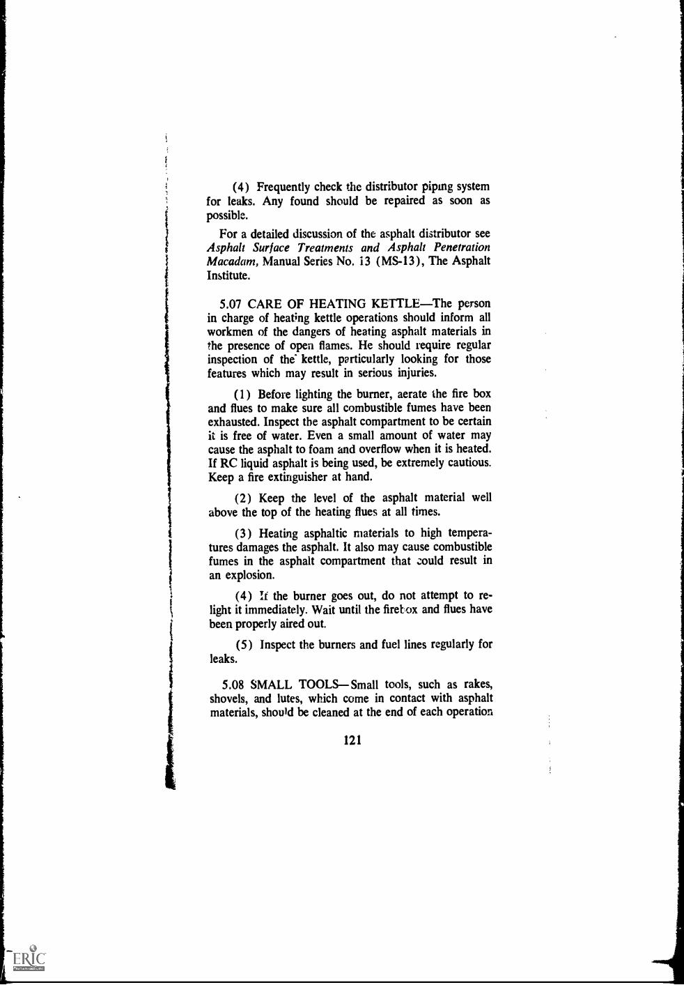
(4) Frequently check the distributor piping systemfor leaks. Any found should be repaired as soon aspossible.
For a detailed discussion of the asphalt distributor seeAsphalt Surface Treatments and Asphalt PenetrationMacadam, Manual Series No, 13 (MS-13), The AsphaltInstitute.
5.07 CARE OF HEATING KETTLEThe personin charge of heating kettle operations should inform allworkmen of the dangers of heating asphalt materials inthe presence of open flames. He should require regularinspection of the' kettle, particularly looking for thosefeatures which may result in serious injuries.
(1) Before lighting the burner, aerate the fire boxand flues to make sure all combustible fumes have beenexhausted. Inspect the asphalt compartment to be certainit is free of water. Even a small amount of water maycause the asphalt to foam and overflow when it is heated.If RC liquid asphalt is being used, be extremely cautious.Keep a fire extinguisher at hand.
(2) Keep the level of the asphalt material wellabove the top of the heating flues at all times.
(3) Heating asphaltic materials to high tempera-tures damages the asphalt. It also may cause combustiblefumes in the asphalt compartment that could result inan explosion.
(4) It the burner goes out, do not attempt to re-light it immediately. Wait until the firebox and flues havebeen properly aired out.
(5) Inspect the burners and fuel lines regularly forleaks.
5.08 SMALL TOOLSSmall tools, such as rakes,shovels, and lutes, which come in contact with asphaltmaterials, should be cleaned at the end of each operation
121

1
i
with kerosene or a similar solvent. If the operation isklontinuous idr a full day, these tools should be cleanedfrequently during the day.

1
1
1
Chapter VI
SOME MAINTENANCE TOOLS
6.01 MAINTENANCE TOOLSIn this chapter arepictures of a few of the tools that ease the job of main-taining pavements. Several mandacturers may producethe same type of tool. Therefore, the following illustra-tions represent types rather than brands. The ones pic-tured were selected at random and do not imply endorse-ment of any particular make by The Asphalt Institute.
Ficure VI-1Asphalt pouring pot
123
;
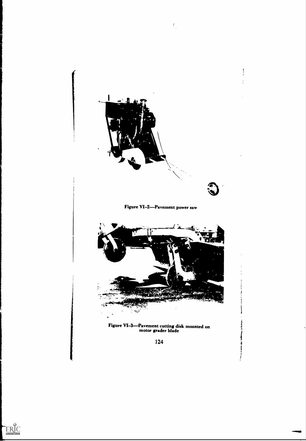
\
Figure VI-2Pavement power saw
t
-ere..0q
gre
Figure VI-3Pavement cutting disk mounted onmotor grader blade
124

1
I
t
1
Figure VI-IInfra-red patch heater
4
,
ti
ii
i
t
I
-44t/=r
Figure VI-5Aluminum lute
125

Figure VI-6Heatedsmoothing iron
N,-1-1-116
Figure VI-7Heating kettle with hand sprayill
126
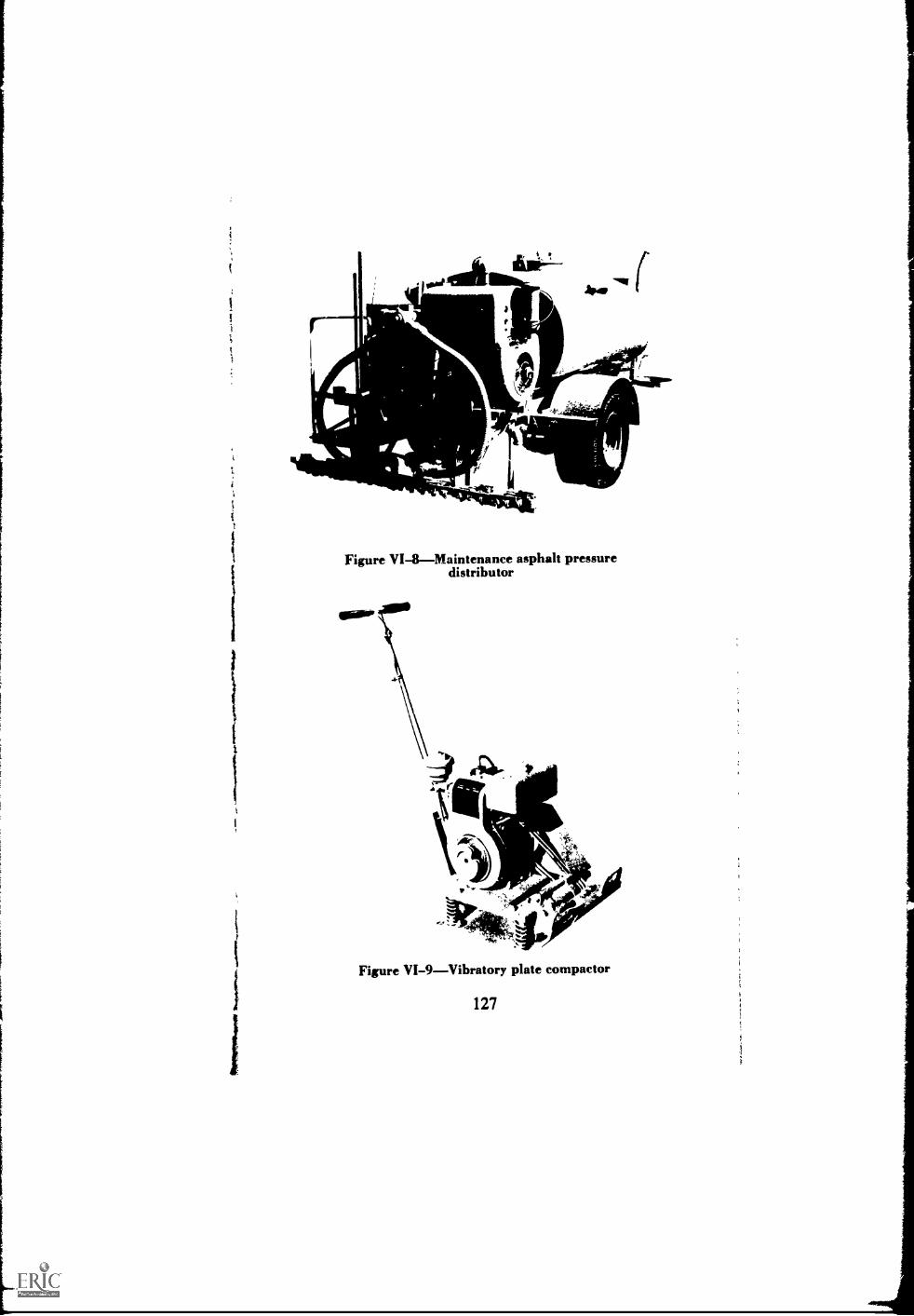
11111._ -
Irkiii61MINFitodd 1111Mkr
$
-1011[.
Figure VI-8---Maintenance asphalt pressuredistributor
Figure VI-9Vibratory plate compactor
127

Figure VIILOImpact compactor
128
t
s
i
i1

Figure VI-IIVibratory roller
1 29
.:
,

-a.-- tar.
Figure VI-12Hot roller
Figure VI-13Slurry-seal machine
130
-

rarr rd.
Figure VI-14Benkehnan beam
..1.111111
Figure VI-15--Stockpile-mix heater
131

.010151.101.111111.11111111111111.1111filipitmemem

!NO-
N)-
Alba.
4,00 1,
eo
Figure VI-17Power router (Photo courtesy OhioHighway Department)
Im
L.*
-
Figure VI-18Shop-made joint-filling device (Photocourtesy Virginia Department of Highways)
133

0
_At
II Ma
.0011111011111111:PP
Figure VI-19Asphalt curb machine
Figure VI-20Asphalt travel plant
134
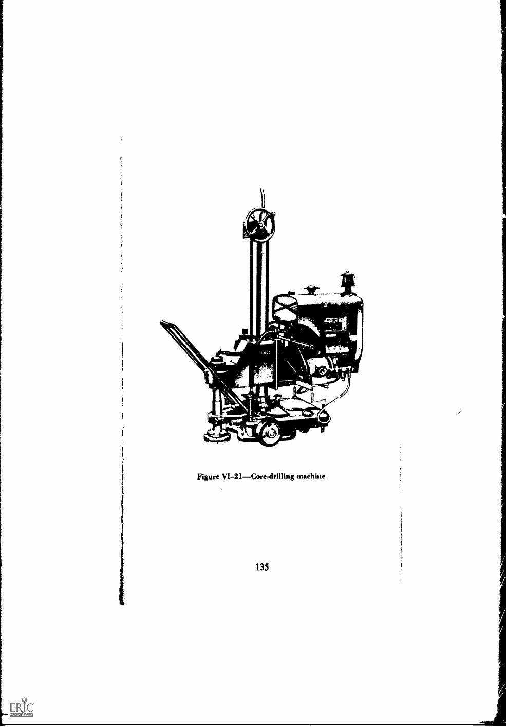
'k
i
1
,,
1
)
Figure VI-21---Core-drilling machine
135
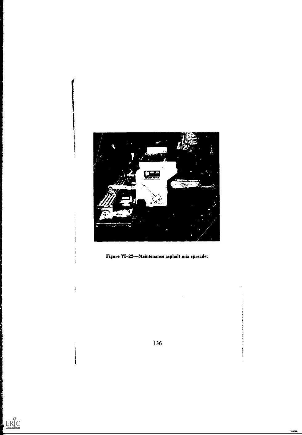
,111111111
$414,
AY("atf:.64%
Figure VI-22Maintenance asphalt mix spreader
136

_.11111.
'el
ar;
Figure VI-23Pavement grinder
137
-stag
1te
i
I
itI
,
Appenci x A
SUGGESTED SPECIFICATIONS
FOR STOCKPILE PATCHING MIXTURES
Specification PM-2
PLANT-MIXED ASPHALT STOCKPILE
MAINTENANCE MIXTURES
A.01 SCOPEFurnish stockpile asphalt maintenance
mixture as specified.
A. General Requirements
A.02 EQUIPMENTThe equipment shall include an
asphalt mixing plant designed, coordinated, and operated
to produce a uniform mixture within the job-mix toler-
ances.
A.03 SAMPLESSamples for all materials proposed
for use under these specifications shall be submitted to
the engineer for test and analysis. The material shall not
be used until it is approved by the engineer.
Sampling of asphaltic materials shall be in accordance
with the latest revision of AASHO Designation T 40
(ASTM Desigmtion D 140). Sampling of mineral ag-
gregate shall be in accordance with the latest revision of
AASHO Desiglation T 2 (ASTM Designation D 75).
A.04 METHODS OF TESTING(1) Asphaltic materials will be tested by the meth-
/39/ 139
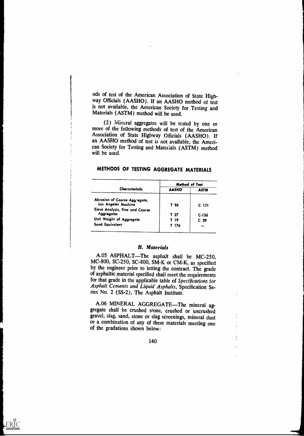
ods of test of the American Association of State High-way Officials (AASHO). If an AASHO method of testis not available, the American Society for Testing andMaterials (ASTM) method will be used.
(2) Minaal aggregates will be tested by one ormore of the following methods of test of the AmericanAssociation of State Highway Officials (AASHO). Ifan AASHO method of test is not available, the Ameri-can Society for Testing and Matelials (ASTM) methodwill be used.
METHODS OF TESTING AGGREGATE MATERIALS
CharacteristicMethod of Test
AASHO ASTM
Abrasion of Coarse Agregate,Los Angeles Machine
Sieve Analysis, Fine and CoarseAggregates
Unit Weight of AggregateSand Equivalent
T 96
T 27T 19T 176
C 131
C-136C 29
B. Materials
A.05 ASPHALTThe asphalt shall be MC-250,MC-800, SC-250, SC-800, SM-K or CM-K, as specifiedby the engineer prior to letting the contract. The gradeof asphaltic material specified shall meet the requirementsfor that grade in the applicable table of Specifications forAsphalt Cements and Liquid Asphalts, Specification Se-ries No. 2 (SS-2), The Asphalt Institute.
A.06 MINERAL AGGREGATEThe mineral ag-gregate shall be crushed stone, crushed or uncrushedgravel, slag, sand, stone or slag screenings, mineral dustor a combination of any of these materials meeting oneof the gradations shown below:
140

MINERAL AGGREGATE GRADATIONSSieve Sizes Grading II la Grading IVb Grading Wc
1 Inch _100
34 inch100 80-100
% inch 100 80-100% inch 80-100 70-90 60-80No. 4 55-75 50-70 48-65No. 8 35-50 35-50 35-50No. 30 18-29 18-29 19-30; No. 200 4-10 4-10 0-8
I,
1
iI
I
C. ConstructionA.07 PREPARATION OF MIXTURE Coarseand fine aggregate shall be fed into the plant in the pro-
portions required to provide a total aggregate conform-ing with the grading specified in Article A.06. The aggre-gate shall be free from visible moisture at the time ofmixing. The asphalt shall be applied at the rate and atthe temperature specified by the engineer to produce afinal mixture containing from 4 to 6 percent liquidasphalt by weight of total mix. The mineral aggregateand the asphalt shall be mixed thoroughly until all aggre-gate particles are completely coated.
A.08 STOCKPILINGThe finished mixture shall bestockpiled on a platform of two (2) inch plank or otherapproved level storage space. When payment is to bemade upon a cubic yard basis the stockpile shall beshaped to facilitate accurate volume measurement.
A.09 METHOD OF MEASUREMENTThe quan-tities to be paid for will be as follows:
Weight BasisTotal number of tons of asphaltmaintenance mixture delivered to the stockpile.
Volume BasisTotal number of cubic yards ofasphalt maintenance mixture as measured in the stock-pile.
141

A.10 BASIS OF PAYMENTThe. quantities meas-ured as described in A rticle A.09 will be paid for at thecontract unit price bia for this item. Payment will be infull compmsat7on for furnishing, mixing, hauling, andstockpiling the mixture and for all labor and use of equip-
ment, tools, and incidentals necessary to complete the
work in accordance with these specifications.
Important Notice to the Engineer
(1) Selection of AsphaltThe following may be
used as a guide for selecting the type and grade of asphaltfor the stockpile mixture:
MC-250--For immediate use under hot or mod-
A.06 will normally be in the range of 4 to 6 per cent by
erate wcAtther conditions, or for use within ashort time after stockpiling.
MC-800For use within short time after stock-
piling.
SC-250For long period storage in hot, dryclimates.
SC-800--For long period storage.
SM-kMix can be designed for use within ashort time after stockpiling or for long storageperiod.CM-KMix can be designed for use within ashort time after stockpiling or for long storageperiod.
(2) Amount of AsphaltThe amount of asphaltrequired fer the aggregate grading specified in Article
111
weight of total mix.
142

Specification RM-4
MIXED-IN-PLACE ASPHALT STOCKPILEMAINTENANCE MIXTURES
A.11 SCOPEFurnish stockpile asphalt maintenancemixture as specified.
A. General Requirements
A.12 EQUIPMENTThe equipment includes travelmixers; rotary mixers; motor graders; and an asphaltpressure distributor meeting the following requirements:
The pressure distributor shall be designed andoperated to distribute the asphaltic material in a uni-form spray without atmintion.
The distributor shall be equipped with a bitu-meter having a dial registering feet of travel per min-ute. The dial shall be visible to the truck driver sothat he can maintain the constant speed required forapplication at the specified rate.
The pump shall be equipped with a tachometerhaving a dial registering gallons per minute passingthrough the nozzles. The dial shall be readily visibleto the operator.
Means for indicating accurately the temperatureof the asphaltic material in the distributor at all timesshall be provided. The thermometer well shall not bein contact with, or close to, a heating tube.
The normal width of application of the spray barshall not be less than 12 feet, with provision for theapplication of lesser width when necessary. A hoseand spray nozzle attachment shall be provided forapplying asphaltic material to patches and areas inac-cessible to the spray bar.
143
;t
The distributor shali be equipped with heatingattachments and the asphaltic material shall be circu-lated through the spray bar during the entire heatingprocess.
Multiple-blade drags or other equipircnit may beused in addition to or in lieu of the specified mixingequipment when approved by the,engineer.
A.13 SAMPLESIf any portion of the in-place roadmaterials are to be used in the construction the engineerwill furnish the contractor with the test results and im-provement requirements, if any, for the in-place mate-rials. Samples of all other materials proposed for useunder these specifications shall be submitted to the engi-nee r for test Ind analysis. The material shall not be useduntil it is approved by the engineer.
Sampling of asphaltic materials shall be in accordancewith the latest revision of Sampling Asphalt Products forSpecification Compliance, IS-133, The Asphalt Institute.
way Officials (AASHO). If an AASHO method of test
AASHO method of test is not available, the AmericanSociety for Testing and Materials (ASTM) method will
be used.
144
ods of test of the American Association of State High-
is not available, the American Society for Testing and
more of the following methods of test of the AmericanAssociation of State Highway Officials (AASHO). If an
Materials (ASTM) method will be used.
(1) Asphaltic materials will be tested by the meth-
(2) Mineral aggregates will be tested by one or
Sampling of mineral aggregate shall be in accordancewith the latest revision of AASHO Designation T 2(ASTM Designation D 75).
A.14 METHODS OF TESTING
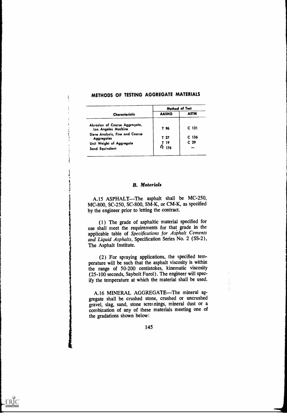
METHODS OF TESTING AGGREGATE MATERIALS
Characteristic
Method of TestASTMAASHO
Abrasion of Coarse Aggregate,Los Angeles Machine
Sieve Analysis, Fine and CoarseAggregates
Unit Weight of AggregateSand Equivalent
T 96
T 27T 194 176
C 131
C 136C 29
B. Materials_
A.15 ASPHALTThe asphalt shall be MC-250,MC-800, SC-250, SC-800, SM-K, or CM-K, as specifiedby the engineer prior to letting the contract.
(1) The grade of asphaltic material specified foruse shall meet the requirements for that grade in theapplicable table of Specifications for Asphalt Cementsand Liquid Asphalts, Specification Series No. 2 (SS-2),The Asphalt Institute.
(2) For spraying applications, the specified tem-perature will be such that the asphalt viscosity is withinthe range of 50-200 centistokes, kinematic viscosity(25-100 seconds, Saybolt Furol). The engineer will spec-ify the temperature at which the material shall be used.
A.16 MINERAL AGGREGATEThe mineral ag-gregate shall be crushed stone, crushed or uncrushedgravel, slag, sand, stone screenings, mineral dust or acombination of any of these materials meeting one ofthe gradations shown below:
145

MINERAL AGGREGATE GRADATIONS
Sieve SizePrcent Passing, by Weight
Grading IVa Grading IVb Grading IVc
1 inch100
34 inch 100 80-1001/2 inch 100 80-10034 inch 80-100 70-90 60-80No. 4 55-75 50-70 48-65No. 8 35-50 35-50 35-5CNo. 30 18- 29 18-29 19-30No. 200 4-13 4-10 0-8
C. Construction
Alternate 1Travel MixingA.17 PREPARATION OF MIXTURECoarse and
fine aggregate shall be deposited in a single windrow inthe proportions required to provide a total aggregateconforming with the grading specified in Article A.16.Unless the travel mixer is equipped to measure and applyasphalt during the mixing operation, the windrow shallbe flattened and the application shall be made with theasphalt distributor. The aggregate shall be free fromvisible moisture at the time ot mixing. The asphalt shallbe applied at the temperature and rate specified by theengineer to produce a final mixture containing from 4 to6 per cent liquid asphalt by weight of total mix. Themineral aggregate and the asphalt shall be mixedthoroughly until all aggregate particles are completelycoated.
Alternate 2Blade Mixing
A.18 PREPARATION OF MIXTURE(1) Coarse and fine mineral aggregate shall be de-
posited in a single wim:row in the proportions required
146
to provide a total aggregate ccnforming with the grad-ing specified in Article A.16. After the proportions ofcoarse and fine aggregate are adjusted, the total looseaggregate shall be mixed thoroughly with a motor grader.It shall then be bladed into a single truncate,' windrow ofuniform cross-section for measurement and adjustmentas may be directed by the engineer.
(2) Immediately prior to application of the asphalt,the windrow of mixed aggiegate shall be bladed to auniform cross-section approximately two (2) inchesthick. If damp, it shall first be bladed back and forthuntil surface dry. Upon the layez of graded aggregate,the asphalt shall be applied uniformly with the asphaltdistributor at the temperature and at the rate specified bythe engineer. The aggregate and asphalt shall be mixedas described in paragraph (3), following. Successivetreatments of asphalt shall then be applied and mixedin the quantities, not exceeding one-half (1/2 ) gallon persquare yard each, directed by the engineer.
(3) The motor grader shall follow the distributorimmediately after each application of asphalt and shallcontinue to operate on the treated strip until all freeasphalt is mixed into the aggregate. After the aggregatehas received its total application of asphalt, mixing shallcontinue until a thoroughly uniform mixture is produced.If, before the process is completed, the mixture shouldbecome wet, the mixing operation shall be continueduntil it dries out. After final mixing the material shallbe brought to a single windrow.
A.19 STOCKPILINGThe finished mixture shall bestockpiled on a platform of two (2) inch plank or otherapproved level storage space. When payment is to bemade upon a cubic yard basis the stockpile shall beshaped to facilitate accurate volume measurement.
A.20 METHOD OF MEASUREMENTThe quan-tities to be paid for wil be as follows:
Weight BasisTotal number of tons of asphaltmaintenance mixture delivered to the stockpile.
147

Volume BasisTotal number of cubic yards of as-phalt maintenance mixture as measured in the stockpile.
A.21 BASIS OF PAYMENTThe quantities meas-
148
ured as described in Article A.20 will be paid for at thecontract unit price bid for this item. Payment will be infull compensation for furnishing, mixing, hauling, andstockpiling the mixture and for all labor and use ofequipment, tools, and incidentals necesary to complete
the work in accordance with these specifications.
Important rotice to the Engineer
(1) Selection of AsphaltThe following may beused as a guide for selecting the type and grade of as-phalt for the stockpile mixture:
MC-250--For immediate use under hot or mod-erate weather conditions, or for use within shorttime after stockpiling.MC-800For use within short time after stock-
piling.SC-250For long period storage in hot, dry
I climates.SC-800For long period storage.SM-KMix can be designed for use within ashort time after stockpiling or long storage period.CM-KMix can be designed for use within ashort time after stockpiling or for long storageperiod.
(2) Amount of AsphaltThe amount of asphaltrequired for the aggregate grading specified in ArticleA.16 will normally be in the range of 4 to 6 per centby weight of total mix.
(3) EquipmentThe blade-mixing portion of thesespecifications is written to require a motor grader forthe mixing process. If other equipment, such as diskharrows and multiple blade drags, must be used theyshould be added in Articles A.12, A.18 (1) and
A.18 (3).
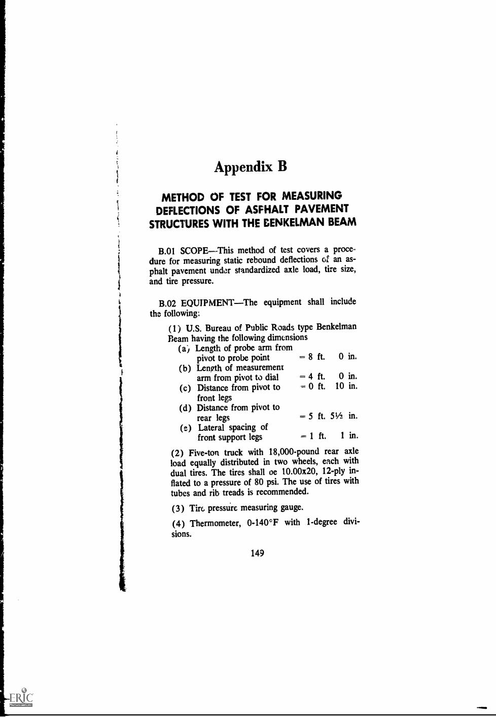
Appendix B
METHOD OF TEST FOR MEASURINGDEFLECTIONS OF ASFHALT PAVEMENT
STRUCTURES WITH THE GENKELMAN BEAM
B.01 SCOPEThis method of test covers a proce-dure for measuring static rebound deflections of an as-phalt pavement under standardized axle load, tire size,and tire pressure.
B.02 EQUIPMENTThe equipment shall includethe following:
(1) U.S. Bureau of Public Roads type BenkelmanBeam having the following dimonsions
(a) Length of probe arm frompivot to probe point = 8 ft. 0 in.
(b) Length of measurementarm from pivot to dial = 4 ft. 0 in.
(c) Distance from pivot to = 0 ft. 10 in.front legs
(d) Distance from pivot torear legs = 5 ft. 51/2 in.
(e) Lateral spacing offront support legs = 1 ft. 1 in.
(2) Five-ton truck with 18,000-pound rear axleload equally distributed in two wheels, each withdual tires. The tires shall oe 10.00x20, 12-ply in-flated to a pressure of 80 psi. The use of tires withtubes and rib treads is recommended.
(3) Tiro pressure measuring gauge.
(4) Thermometer, 0-140°F with 1-degree divi-sions.
149
B.03 PROCEDURE(1) Select and mark a point to be tested in the out-
er wheel path.(2) Center the dual tires of the right rear wheel
of the truck above the selected point.(3) Insert the probe of the Benkelman Beam be-
tween the dual tires ard place the probe pointover the selected test point.
(4) Remove the locking pin from the beam :anddrop the probe point to the pavement. Adjustthe rear legs so that the plunger of the beam isin contact with the dial gauge stem. Adjust thedial gauge to read approximately 0.4 inch.
(5) Start buzzer.(6) Record initial reading of dial when dial needle
stops moving.(7) Move truck forward about 30 feet.(8) Record final reading of dial when the dial
needle stops moving.
B.04 CALCULATIONS Subtract the final dialreading from the initial dial reading. The difference multi-plied by 2 is the Actual pavement deflection.
B.05 MISCELLANEOUS Obtain air temperatureand aPproximate pavement temperature.
B.06 REPORTThe report shall include the follow-ing:
(a) Test location(b) Deflection(c) Air and pavement temperatures.
150

- AN--..N *,-"-Nt ^wrai.0.1044,4-4r7tr.i.y.i.oe -60 '1,-.4.1^1oh. Ow .4,4- 4, "o...;,r4p ' 44+.4.0- 61,410,444.1.fturAiNiacoal

A
Aggregate seals andsealsPatching, 26-28Properties and use in
maintenance, 115. TableIV-1, 108-109
Alligator cracks, 17-29 seealso C racking
American Public WorksAssn. Maintenance publi-cation, 1
Asphalt and Asphalt mix-tures used in maintenanceAsphalt cements, 107-110Asphalt emulsions, 111Asphalt cutbacks (RC-MC) and Road Oil (SC),111
Comparison of newand old liquid as-phalt grades at 140°F. (60°C), Figure IV-], 1/0
Crack-filling materials,116
Patching materials, 116-118
Prime coats, 112Properties and recom-
mended uses, 107, TableIV-1, 108-109
Seal coats, 113-116Tack coats, 113
Asphalt cements, propertiesand uses in maintenance,107-110, Table IV-1, 108-109
Asphalt concreteDefinition, 1
Patching material, 116Recommended use in
maintenance, Table IV-1, 108-109
Asphalt curb machine, Fig-ure VI-19, 134
cant!
INDEXAsphalt emulsions, proper-
ties and uses in mainte-nance, 111-112, Table
IV-i, 108-109
Asphalt emulsion slurry sealDefinition, 2Patching, 29Properties and use in
maintenance, 114-115,Table IV-1, 108-109
Proportions and grada-tion, 115
Asphalt fog sealDefinition, 2Properties and use in
maintenance, 114, TableIV-1, 108-109
Asphalt leveling course,definition, 2
Asphalt overlayDefinitior, 2Use, 85
Asphalt pavement definlhoi,2Maintenance, 11-79
Asphalt pavement structure,definition, 2
Asphalt pouring pot, FigureVI-1, 123
Asphalt prime coatDefinition, 2Properties and use in
maintenance, 112, TableIV-1, 108-109
Asphalt seal coatsDefinition. 3Properties and use in
maintenance, 113-116,Table IV-1, 108-109
Asphalt surface treatmentsDefinition, 3Uses, Table IV-1, 108-
109
/5---/ 153 -
Asphalt tack coatsDefinition, 3Properties and uses in
maintenance, 113, TableIV-1, 108-109
Asphalt undersea!Definition, 4Uses in PCC pavement
maintenance, 84Asphalt uses in PCC pave-
ment maintenance, 81
B
Backfilling hole with plant-mix, Figure I1-7, 21
Benkelman BeamFigures II-1, 13, VI-14,131Function, 12Method of test for meas-
uring deflections of as-phalt pavement struc-tures; calculations,equipment, procedure,reports .and scope, 149-150
Bleeding or flushing asphalt,description, cause and re-pair, 70-73
Buckling or rigid type pave-ment, See Blow-up, 101
CChannels (Ruts), description,
cause and repair, 47-51Core-drilling machine, Fig-
ure VI-21, 135Corner cncks in PCC pave-
ments, 91-92Corrugations and shoving,
description, cause and re-pair, 51-54, Figures 11-50to 11-52, 52-54
Crack-filling materials, 116Recommended use, Table
IV-1, 108-109Cracking in asphalt pave-
ments, 17-46
Alligator cracks, descrip-tion, cause and repair,17-29, Figure 11-4, 17Aggregate seal coat
patch, 26-28, Figures11-17 to 11-19, 27-28
Deep patch, 18-19, Fig-ures 11-5 to 11.10,20-22
Skin patch, 22, 23, Figs.11-11 to 11-16, 23-26
Slurry seal patch, 29Edge cracks, description,
cause and repair, 29,30, Figures 11-20 to II-23, 29-31
Edge joint cracks, descrip-tion, cause and repair,Figure 11-24, 32
Lane joint cracks, descrip-tion, cause and repair,Figure 11-25, 33
Reflection cracks, descrip-tion, cause and repair,33-35, Figures 11-26 to11-29, 34-36
Shrinkage cracks, descrip-tion, cause and repair,37-39, Figures 11-30 toII-3d, 37-40
Slippage cracks, descrip-tion, cause and repair,41, 42, 45, Figures II-35 to 11-42, 41-45
Widening cracks, Figure11-43, 46
Cracks in PCC pavements,see Joints and Cracks,85-96
Cutbacks (RC-MC) andRoad Oil (RC) propertiesand use in maintenance,111, Table IV-1, 108-109,Figure IV-1, 110
DDeep-Lift asphalt pavement,
definition, 3
- 154 -

Deep patch, 18-22Deep-Strength asphalt pave-
ment, definition, 3Definitions, 1-4Deflection
Detinition, 3Test method, Benkelman
BeamFigures 11-1, 13, V1-H,131Function, 12Procedure, 149-150
Depressions in grade, de-scription, cause and re-pair, 54-60
Diagonal cracks in PCCpavement, 92, 93
Disintegration, asphalt pave-mentsGeneral, 62Pot holes, description,
cause and repair, 63-65,Figures 11-64 to 11-70,62-68
Raveling, description,cause and repair, 68-70,Figure 11-71, 69
Disintegration, portiand ce-ment concrete pavementsBlow-ups, 101, Figures III-
15, 111-16, 102General, 101Scaling and, Figure III-17,
103Spalling and, Figure III-
18, 104
Distortion, asphalt pave.mentsChannels (Ruts), 47-49,
Figures 11-44 to 11-49,47-51
Corrugations and shoving,51-54, Figures 11-50 toII-52, 52-54
General, 47Grade depressions, 54-56,
59, Figures II-53 to II-61, 55-60
Upheaval and, Figure II-62, 61
Utility-cut depression, 61,Figure 11-63, 62
Distortion, portland cementconcrete pavementsFault, 98, Figure III-13,
99General, 97, 98Pumping, 99, Figure III-
14, 100Distributor, care of, 120,
Figure VI-8, 127Drainage maintenance, 6
EEdge cracks, description,
cause and repair, 29-31,Figure 11-21, 29
Edge joint cracks, descrip-tion, cause and repair,Figure 11-24, 32
Equipment, maintenance,care of, 119-122Distributor, 120Heating kettle, 121Records of servicings and
repairs, 120Responsibility, assign-
ment, 119Operator, 119Repair shop, 119
Small tools, 121Expansion joints, Table IV-
1, 108-109
FFlexible pavement structure
(asphalt), definition, 2Flushing or bleeding asphalt,
description, cause and re-pair, 70-30
Fog seal (asphalt emulsion)Definition, 2Properties and uses in
maintenance, 114, TableIV-1, 108-109
Full-Depth asphalt pavement(TA), definition, 3, 4
- 155

GGrade depressions, descrip-
tion, cause and repair,54.60
Granular bases and mois-ture, 11
HHeating kettle, care of, 121,
Figure VI-7, 126Hot roller, Figure VI-12, 130
IImpact compactor, Figure
VI-10, 128Infra-red patch heater, Fig-
ure VI-4, 125
IYoint-filling device, Figure
VI-18, 133Joint and crack sealing PCC
pavementsDescription, cause and re-
pair, 81-84, Figures III-1, 111-2,83, 84
Materials, Table III-1, 82Joints and cracks in PCC
pavementsDescription, cause and re-
pair, 85, 87, Figure III-3, 87
Joint resealing, 88-90, Fig-ures 111-4, 111-5, 89,111-6, 111-7, 90Excessive seal, 90, 91
Sealing cracks, 91Corner cracks, 91, Figure
111-8, 92Diagonal cracks, 92, Fig-
ure 111-9, 93Longitudinal cracks and
Figure III-10, 94Restraint cracks and Fig-
ure I11-11, 95Transverse cracks, 96,
Figure 111-12, 97
L
Lane joint cracks in asphaltpavement, cause and re-pair, 3 3
Leveling course, asphalt, def-inition, 2
Liquid asphalts, propertiesand uses in maintenance,111, Table IV-1, 108-109,Figure IV-1, 110
Longitudinal cracks in PCCpavements, 94
Lute, aluminum, Figure VI-5, 125
M
Maintenance asphalt mixspreader, Figure VI-22,136
Maintenance asphalts andasphalt mixtures recom-mended uses, Table IV-1,108-109
Maintenance, asphalt pave-ments, 11-80Asphalt pavement types,
11
Benkelman beam, 12, Fig-ure II-1,13
Cracking, 17-46Disintegration, 62-69Distortion, 47-61Granular ba ..!s and mois-
ture, 11Patching, 13-29Prime and Tack coats, 14Skid hazard, 70-75Surface treatments, spe-
cial problems, 76-80Maintenance, introduction, 1
Defect recurrence, preven-tion of, 7
Definition, 4Drainage systems, 6Preventive maintenance, 5Repair promptly, 6
-- 156 -

Safety program, 10Skilled personnel impor-
tance, 8Street maintenance, 7, 8Weather, importance of,
9, 10Why maintenance is ne-
cessary, 5Maintenance Manual
Foreword, vScope, 1
Maintenance of PCC pave-ments, asphalt in the, 81-106Asphalt uses, 81Disintegration, PCC pave-
ments, 101Distortion, PCC pave-
ments, 97Joint and crack sealing,
81-85, Figures III-1, III-2, 83, 84
Joints and cracks in PCCpavements, 85
Materials, Table III-1, 82Overlays, 85Skid hazard, PCC pave-
ments, 105Undersea ling, 84, 85
Maintenance tools, 123-1 37Mixed-in-place asphalt pave-
mentsDefinition, 4General, 117, Table IV-1,
108-109Specification RM-4, 143-
148Asphalt, selection of,
148General requirements,
143Materials, asphalt, 145,Measurement, method
of, 147Mineral aggregate, 145,
146Mixing, blade, 146, i47Mixing, travel, 146Sampling, 144
Stockpiling, 147Testing, 144, 145
Mixer, small portable, Fig-ure VI-16, 132
Moisture and granular bases,1 1
0Overlay, asphalt
Definition, 2PCC pavement mainte-
nance, 85
PPatching asphalt pavements
Aggregate seal coat, 26,27, Figures 11-17 to II-19, 27, 28
Deep patch, 18, 19, Fig-ures II-5 to II-10, 20-22
Mixtures, 13-16Skin patch, 22, 23, Fig-
ures II-11 to 11-16, 23-26
Slurry-seal patch, 29Patching materials, proper-
ties and use, Table IV-1,108-109Asphalt concrete, 116Cold-laid paving mixtures,
117Plant mixes with liquid
asphalt, cold laid, 117Specification PM-2, 139-
142Road mixes with liquid
asphalt, 117Specification RM-4, 143-
148Patching mixtures, 1 3-16
Comnacting, 15, Figure11-3, 16
General, 13Placing, 14, Figure 11-2,
15
Prime and tack coats, 14Pavement cutting disk, Fig-
uce V1-3, 124Pavement, definition, 4
- 157 -

Pavement grinder, FigureVI-23, 137
Pavement power saw, FigureVI-2, 124
Pavement structure, defini-tion, 4
Pavement structure (asphalt),definition, 2
Penetration macadam, Table1V-1, 108-109
Plant mixDefinition, 4General, 117, Table IV-1,
108-109Specification PM-2, 139-
142Construction, 141General requirements,
139Materials, asphalt, 140,
Selection, 142Measurement, method
of, 141Mineral aggregate, 140,
141Payment, basis of , 142Samples, 139Stockpiling, 141Testing, 139, 140
Surface treatments, defini-tion, 4
Polished aggregate ir sur-faces, description, causeand repairAsphalt pavements, 74-76PCC pavements, 105, 106
Portland cement concretepavements, asphalt inmaintenance of, 81-106
Pot holes, description, causeand repair, 62-68, Figures11-64, 11-65, 63, 64
Power router, Figure VI-17,133
P!'eventing defect recurrence,7
Preventive maintenance, 5Prime coat (asphalt)
Definition, 2
Properties and use inmaintenance, 112, TableIV-1, 108-109
Prime and tack coats fordeep patch, 14
RRaveling, descriptioL, cause
and repair, 68-70Reflection cracks, descrip-
tion, cause and repair, 33-36
Responsibility for mainte-nance of equipment, 119
Restraint cracking, PCCpavements, 95, 96
Road-mix, definition, 4, seealso Mixed-in-place
Ruts and channels, 47-51
S
Safety program in mainte-nance, 10
Seal coats (Asphalt)Definition, 3Properties and use in
maintenance, 113-116,Table IV-1, 108-109
Sealing cracks and joints inPCC pavements, 81-96
Shoving and corrugations,51-54, Figures 11-50 to II-52, 52-54
Shrinkage cracks, 37-40Skid hazard, asphalt pave-
mentsBleeding or flushing as-
phalt, 70-73, Figures11-72 to 11-74, 71, 73
General, 71Polished aggregate and
Figures II-75 to 11-77,74-76
Skid hazard, PCC pave-ments, 105General, 105Polished aggregate, 105,
Figure 111-19, 106
- 158 -
Skilled personnel, impor-tance in maintenance, 8
Skin patch, 22-26Slippage cracks, 41-45Slurry seals (Asphalt emul-
sion)Definition, 2Machine, Figure VI-13,
130Patching, 29Properties and use in
maintenance, 114, 115,Table IV-1, 108-109
Proportions and gradation,115
Smoothing iron, heated, Fig-ure VI-6, 126
Squeegee, Figure III-1, 83Stockpile-mix heater, Figure
VI-15, '131Stockpile patching mixtures
Specification PM-2, plant-mix, 139-142
Specification RM-4, mixed-in-place, 143-148
Straightedging, Figures 11-45,48, 11-54, 57, 11-59, 59
Street maintenance, 7Surface treatments
Definition, 3Plant mix, defined, 4Special problems, genval,
76Loss of cover aggregate,
77, 78, Figure 11-78, 77Longitudinal streaking, 78,
Figure 11-79, 79Transverse streaking, 79
TA (Full-Depth asphalt pave-ment), definition, 3, 4
- 159
Tack coatApplications, Figures 11-6,
20, 11-14, 25, 11-21, 30,11-32, 39, 11-38, 43, II-46, 49, 11-57, 58, 11-65,64
Definition, 3Propel ties and uses in
maintenance, 113, TableIV-1, 108-109
Tools, maintenance, 123-137Transverse cracks in gICC
pavements, 96Travel plant, asphalt, Figure
VI-20, 134
Undersealing asphaltDefinition, 4PCC pavement mainte-
nance, in, 84, 85Upheaval (Distortion), de-
scription, cause and re-pair, 61
Utility cut depressions, 61,62
VVibratory plate compactor,
Figure VI-9, 127Vibratory roller, Figure VI-
II, 129
Washboarding, 51-54, seealso Corrugations andShoving
Weather, importance inmaintenance, 9, 10
Widening cracks, Figure II-43- 46

SOME IMPORTANT TECHNICALPUBLICATIONS OF THE ASPHALT INSTITUTE
Specification Series
Specifications and Construction Methods for Asphalt Concreteand Other Plant-Mix Types (55-1)
Specifications for Asphalt Cements and Liquid Asphalt (55-2)Specifications and Construction Methods for Asphalt Curbs
and Gutters (SS-3)Specifications for Undersea ling Portland Cement
Concrete Pavements with Asphalt (SS-6)Asphalt Protective Coatings for Pipe Lines (CS-96)
Manual Series
Thickness DesignAsphalt Pavement Structures for Highwaysand Streets (MS-1)
Mix Design Methods for Asphalt Concrete and other Hot-MixTypes (MS-2)
Asphalt Plant Manual (MS-3)The Asphalt Handbook (MS-4)Introduction to Asphalt (MS-5)Asphalt Pocketbook of Useful Information (MS-6)Asphalt Mulch Treatment (MS-7)Asphalt Paving Manual (MS-8)Asphalt for Off-Street Paving and Play Areas (MS-9)Soil Manual for Design of Asphalt Pavement Structures (MS-10)Asphalt Pavement for Airports (MS-11)Asphalt in Hydraulic Structures (MS-12)Asphalt Surface Treatments and Asphalt Penetration
Macadam (MS-13)Asphalt Mixed-in-Place (Road Mix) Manual (MS-14)Drainage of Asphalt Pavement Structures (MS-15)
Copies of these and other Asphalt Institute publications are availableat any Institute field engineering office listed in Ole end papers,or at Institute Headquarters office at College Park. Maryland.
/46/161

THE ASPHALT INSTITUTEEXECUTIVE OFFICES AND LABORATORIES
Asphalt Institute Building
College Park, Maryland 20740
MEMBERS OF THE ASPHALT INSTITUTE(As of November I, 1967)
The Asphalt Institute is an international, nonprofit assodation sponsoredby members of the petroleum asplialt industry to serve both users andproducers of asphaltic materials through programs of engineeringservice, research and education. Membership is limited to refiners ofasphalt from crude petroleum. Institute membeis provide qualityproducts and advocate quality construction and timely maintenance.
A total of 53 Members have headquarters offices in:United States 39 Europe 6Canada 7 Middle East 1
ALLIED MATERIALS CORPORATIONOklahoma City
AMERICAN OIL COMPANYChicago
APCO OIL CORPORATIONOklahoma City
ASHLAND OIL & REFINING COMPANYAshland, Kentucky
ATLANTIC RICHFIELD COMPANYAtlantic DivisionPhiladelphiaRichfield DivisionLos Angeles
BRITISH AMERICAN OIL COMPANY LTD.Toronto, Ontario, Canada
BP CANADA LIMITEDMontreal, Quebec, Canada
BRITISH PETROLEUM COMPANY LTD.London, England
BYERLYTE COMPANY OF KOPPERS COMPANY, INC.Cleveland
CANADIAN PETROFINA LIMITEDMontreal, Quebec, Canada
CHAMPLIN PETROLEUM COMPANYFort Worth, Texas
CHEVRON ASPHAI T COMPANYSon Francisco and Baltimore
COMPANIA ESPANOLA DE PETROLEOS, S.A.Madrid, Spain

CONTINENTAL OIL COMPANYHouston
DOUGLAS OIL COMPANY OF CALIFORNIALos Angeles
EDGINGTON OIL REFINER/ES, INC.Long Beach, California
ESSO STANDARD EASTERN, INC.New York
FARMERS UNION CENTRAL EXCHANGE, INC.Laurel, Montana
GOLDEN BEAR OIL COMPANYA Division of Witco Chemical Company, Inc.
Los Angeles
GREAT NORTHERN OIL COMPANYSt. Paul
Industrial Asphalt, Inc., Agent forGULF OIL CORPORATION
Los Angeles
HUMBLE OIL & REFINING COMPANYHouston
HUNT OIL COMPANYDallas
HUSKY OIL CANADA LTD.Calgary, Alberta, Canada
HUSKY OIL COMPANYCody, Wyoming
IMPERIAL OIL LIMITEDToronto, Ontario, Canada
KERR-McGEE CORPORATIONOklahoma City
LEONARD REFINERIES, INC.Alma, Michigan
LION OIL COMPANYHydrocarbons Division, Monsanto Company
El Dorado, Arkansas
MACMILLAN RING-FREE OIL CO., INC.New York and El Dorado, Ark.
MARATHON OIL COMPANYFindlay, Ohio
MOBIL OIL CORPORATIONNew York
MOBIL OIL CCRPORATIONInternational DivisionNew York

f
MURPHY OIL CORPORATIONEl Dorado, Arkansas
NESTE OYHlsinki, Finland
NEWHALL REFINING CO., INC.Newhall, California
NORTHWESTERN REFINING COMPANYSt. Paul Park, Minnesota
AB NYNAS-PETROLEUMNynashamn, Sweden
PAZ OIL COMPANY LIMITEDHaifa, Israel
PHILLIPS PETROLEUM COMPANYBartlesville, Oklahoma
RAFFINERIE BELGE DE PETROLES, S.A.Antwerp, Belgium
SHELL CANADA LIMITEDToronto, Ontario, Canada
SHELL INTERNATIONAL PETROLEUM CO., LTD.London, England
SHELL OIL COMPANYNew York and San Francisco
SINCLAIR REFINING COMPANYNw York
SOUTHLAND OIL COMPANYYazoo City, Mississippi
STANDARD OIL COMPANYOF BRITISH COLUMBIA, LTD.
Vancouver, B.C., Canada
THE STANDARD OIL COMPANY(An Ohio Corporation)
Cleveland
SUN OIL COMPANYPhiladelphia
3UNRAY DX OIL COMPANYTulsa
UNION OIL COMPANY OF CALIFORNIALos Angeles
Pure Oil Company DivisionPalatine, ill.
U. S. OIL AND REFINING COMPANYLos Angeles
WITCO CHEMICAL COMPANY, INC.Pioneer Division
New York
CONTRIBUTOR
ENVOY PETROLEUM CO.Long Beach, California

l
INSTITUTE ENGINEERING OFFICES(As of November 1, 1967)
EASTERN DIVISION
WASHINGTON, D.C. 20006-1901 PennsylvaniaAve.. N.W.
Connecticut, Delaware, District of Columbia,Kentucky, _Maine, Maryland, Massachusetts,New Hampshire, New Jersey, New York,Ohio, Pennsylvania, Rhode Island, Vermont,Virginia, West Virginia
BOSTON, MASS.(Address: 599 North Ave.,Wakefield 01880)
Connecticut, Maine, Massachusetts, NewHampshire, Rhode Island, Vermont
ALBANY, N. Y. 12206-50 Colvin Ave.New York State (except New York City,Westchester County and Long Island)
NEW YORK, N. Y. 10020-1270 Ave. of theAmericas
New York City, Westchester County, LongIsland, New Jersey
HARRISBURG, PA. 17102-800 N. Second St.Pennsylvania
PiCHMOND, VA. 23219Travelers Bldg.Virginia
COLUMBUS, OHIO 43215-50 W. Broad St.Ohio
LOUISVILLE, KY. 40207-4050 Westport RoadKentucky, West Virginia
SOUTHERN DIVISION
NEW ORLEANS, LA. 70130John Hancock Bldg.Alabama, Arkansas, Florida, Georgia,Louisiana, Mississippi, New Mexico, NorthCarolina, Oklahoma, South Carolina, Ten-nessee, Texas
HOUSTON, TEXAS 77027-2400 West Loop SouthTexas
OKLAHOMA CITY, OKLA. 73102Kermac Bldg.Arkansas, Oklahoma, Northern Texas
N^RTH LITTLE ROCK, ARK. 72116-4507 John F.i. nnedy Blvd.
Arkansas
SANTA FE, N. MEX. 87501-10 Radio PlazaNew Mexico, Western Texas
MONTGOMERY, ALA. 36104-79 Commerce St.Alabama, Tennessee
ATLANTA, GA. 30326-3384 Peachtree RoadGeorgia
TALLAHASSEE, FLA. 32303 Tallahassee Bldg.Florida
RALEIGH, N. C. 27605-2016 Cameron St.North Carolina, South Carolina

NORTHERN DIVISION
ST. PAUL, MINN. 55104-276 N. Snelling Ave.Colorado, Idaho, Illinois, Indiana, Iowa,
Kansas, Michigan, Minnesota, Missouri,
Montana, Nebraska, North Dakota, SouthDakota, Utah, Wisconsin, Wyoming
EAST LANSING, MICH. 48823-1019 Trowbridge
RoadMichigan
INDIANAPOLIS, IND. 46205-4165 Millersville
RoadIndiana
SPRINGFIELD, ILL. 62703-2604 S. Sixth St.Illinois (except Chicago), St. Louis County,
Missouri
CHICAGO, ILL. 60656-4950 N. Harlem Ave.Metropolitan Chicago
MADISON, WISC. 53711-4333 Nakoma Rd.
WisconsinAMES, IOWA 50010-430 Fifth St.
IowaKANSAS CITY, MO. 64112-612 W. 47th St.
Kansas, Missouri (except St. Louis Co.),
NebraskaJEFFERSON CITY, MO. 65101-616 Howard St.
Missouri (except St. Louis Co.)
OMAHA, NEBR. 68132-6901 Dodge St.Nebraska
BISMARCK, N. DAK. 58501-206 N. First St.
North Dakota, South DakotaDENVER, COLO. 80215-1401 Saulsbury
Colorado, Utah, WyomingHELENA, MONTANA 59601Power Block
I:Jaho, Montana
PACIFIC COAST DIVISION
BERKELEY, CALIF. 94710-810 University Ave.Alaska, Arizona, California, Hawaii, Nevada,Oregon, Washington
LOS ANGELES, CALIF. 90017-1709 W. 8th St.Southern California
SACRAMENTO, CALIF. 95814Forum BldgCentral and Northern California, Nevada
PHOENIX, ARIZ. 85016-3625 N. 16th St.Arizona
PORTLAND, ORE. 97225-4475 S.W. Schell Is
Ferry Rd.Oregon
OLYMPIA, WASH. 98502-120 Union AvenueBuilding
Alaska, Washington
Printed in U.S.A.

PA
CIF
ICC
OA
ST
TA
MA
PO
RT
LIA
ID
OS
AC
IAM
INT
O
It>H
AW
AII
TH
E A
SP
HA
LTIN
ST
ITU
TE
DIV
ISIO
NA
L A
RE
AS
AN
DO
FF
ICE
S
IN T
HE
UN
ITE
DS
TA
TE
S
NO
RT
HE
RN
MIN
A
AC
/A
MM
ON
LAN
DLO
O
M
OM
! PA
UL
°NA
NA
*f
1W
RO
AN
SIL
D.
war
s an JI
III.S
O a
n
(
EA
ST
ER
N0
TO
N
--..,
----
Th-
':'4N
EW
TO
ME
L.__
,N
AR
RIT
AM
Oi W
CO
UR
OR
PA
NT
;el(
MA
RY
LAN
D
CO
LUM
AU
S 0
r :,:
f7L/
7 M
AIN
INO
TO
NIM
MA
NA
PO
LN.1
'".
.r `
Vte
osm
ono
LOS
*M
OM
S
00C
LAN
OM
A a
n,un
ru *
oat
AT
LAN
TA
*
oc4m
.7.
'moa
n.
TA
IA'1
4AS
IRE
SO
UT
HE
RN
* IN
AD
OU
AR
TM
S
onts
csut
com
a
antr
a m
a A
RIA
OP
PK
I