Australian Society For Concrete Pavements - ASCP … Papers/Paper 02... · Australian Society for...
25
Australian Society for Concrete Pavements 4 th Concrete Pavements Conference Factors Influencing CRCP Performance in Texas Moon Won 1 , P.E., Ph.D. and Pangil Choi 2 , Ph.D. 1 Professor and 2 Senior Research Associate Texas Tech University, USA ABSTRACT As of 2016, there are 21,799 lane kilometres of continuously reinforced concrete pavement (CRCP) managed by the Texas Department of Transportation (TxDOT). CRCP is a premium pavement type, with a higher initial construction cost than jointed plain concrete pavement (JPCP), primarily due to the material and installation cost of steel reinforcement. In Texas, the long-term performance of CRCP has been far superior to that of JPCP. Based on the performance histories of the two Portland cement concrete (PCC) pavement types in Texas, in 2001, TxDOT made it a policy to utilize CRCP when a rigid pavement is selected for projects. Over the years, CRCPs designed and built in accordance with TxDOT’s design standards and specifications have provided overall excellent performance; however, some premature distresses have been observed in CRCP. Since CRCP is more expensive than JPCP, and is placed where heavy truck traffic volume is high, minimizing premature distresses and thus eliminating the need for lane closures for any maintenance work is of prime importance to TxDOT. To achieve the goal of developing near zero-maintenance CRCP, TxDOT has initiated a number of research studies and forensic evaluations, with a primary goal of identifying the mechanisms of premature distresses and developing design standards and construction/materials specifications that would result in minimizing premature distresses and extending CRCP pavement life.
Transcript of Australian Society For Concrete Pavements - ASCP … Papers/Paper 02... · Australian Society for...

Australian Society for Concrete Pavements
4th Concrete Pavements Conference
Factors Influencing CRCP Performance in Texas
Moon Won1, P.E., Ph.D. and Pangil Choi2, Ph.D.
1Professor and 2Senior Research Associate
Texas Tech University, USA
ABSTRACT
As of 2016, there are 21,799 lane kilometres of continuously reinforced concrete pavement
(CRCP) managed by the Texas Department of Transportation (TxDOT). CRCP is a premium
pavement type, with a higher initial construction cost than jointed plain concrete pavement
(JPCP), primarily due to the material and installation cost of steel reinforcement. In Texas,
the long-term performance of CRCP has been far superior to that of JPCP. Based on the
performance histories of the two Portland cement concrete (PCC) pavement types in Texas,
in 2001, TxDOT made it a policy to utilize CRCP when a rigid pavement is selected for
projects.
Over the years, CRCPs designed and built in accordance with TxDOT’s design standards
and specifications have provided overall excellent performance; however, some premature
distresses have been observed in CRCP. Since CRCP is more expensive than JPCP, and is
placed where heavy truck traffic volume is high, minimizing premature distresses and thus
eliminating the need for lane closures for any maintenance work is of prime importance to
TxDOT. To achieve the goal of developing near zero-maintenance CRCP, TxDOT has
initiated a number of research studies and forensic evaluations, with a primary goal of
identifying the mechanisms of premature distresses and developing design standards and
construction/materials specifications that would result in minimizing premature distresses
and extending CRCP pavement life.

ASCP 4th Concrete Pavements Conference 2
Factors Influencing CRCP Performance in Texas, Won
The major findings from those studies and investigations included; (1) structural distresses in
CRCP are rare in Texas where tied-concrete shoulders and stabilized bases were utilized,
(2) most, if not all, of the distresses are due to deficiencies in quality control for materials and
construction, (3) many of what appear to be full-depth failures are actually partial-depth
failures, (4) transverse crack spacing does not appear to have significant effects on long-
term performance, (5) concrete properties, especially the coefficient of thermal expansion
(CTE), have significant effects on major spalling development, and (6) the use of lower
amounts of longitudinal steel than the generally accepted 0.6 % resulted in poor
performance.
Based on these findings, TxDOT revised its CRCP design standards in 2013 and
construction/material specifications in 2014. The implementation of those design standards
and specifications is expected to further enhance long-term CRCP performance in Texas.

ASCP 4th Concrete Pavements Conference 3
Factors Influencing CRCP Performance in Texas, Won
Introduction
In Texas, various types of Portland cement concrete (PCC) pavement have been used. They
include jointed plain concrete pavement (JPCP), jointed reinforced concrete pavement
(JRCP), continuously reinforced concrete pavement (CRCP), precast concrete pavement
and cast-in-place prestressed concrete pavement. The last two types were built as test
sections for research and implementation projects. In general, the performance of JRCP was
not as good as JPCP or CRCP, therefore TxDOT discontinued the use of this pavement
type. Accordingly, only JPCP and CRCP are now utilized in Texas. Figure 1 illustrates the
lane kilometres of JPCP and CRCP managed by TxDOT from 2006 to 2016. It shows that
the usage of CRCP has increased while that of JPCP has steadily decreased.
Figure 1 Lane kilometres of PCC pavement managed by TxDOT
The reason for this trend is that, in 2001 TxDOT made it a policy to utilize CRCP when a
rigid pavement is selected for projects, and since then most of the PCC pavements built in
Texas, if not all, were CRCP. TxDOT districts are allowed to use JPCP in certain locations or

ASCP 4th Concrete Pavements Conference 4
Factors Influencing CRCP Performance in Texas, Won
with the approval from the administration. The TxDOT policy of exclusive use of CRCP was
based on the overall poor performance of JPCP and the excellent performance of CRCP.
Figure 2 shows the percentage of lane miles with distress scores of 80 or above for various
pavement types for the last 4 years (TxDOT PMIS, 2016). CRCP has the highest
percentage, while JPCP has the lowest.
Figure 2 Percentage of lane miles with distress score of 80 or above
Figure 3 Percentage of lane miles with ride score of 3.0 or above
Figure 3 illustrates the percentage of lane miles with a ride score of 3.0 or above for various
pavement types for the last 4 years, which clearly indicates the superior ride quality of CRCP

ASCP 4th Concrete Pavements Conference 5
Factors Influencing CRCP Performance in Texas, Won
to other pavement types, better than that of asphalt concrete pavement. It also indicates the
poor ride quality of JCPC.
The superior performance of CRCP over other pavement types in Texas is the result of
continuous efforts made by TxDOT. Over the years, TxDOT has sponsored a number of
research studies on CRCP behaviour and performance, with the objectives of obtaining
optimum CRCP performance by improving design standards and specifications. This also
resulted in a better understanding of CRCP behaviour under various loading conditions, as
well as the mechanisms of various distress types in CRCP. In addition, a long-term CRCP
performance study was conducted, which spanned from 2005 to 2013 (Choi, et al, 2014).
This study evaluated the field performance of CRCP throughout Texas, and investigated
detailed structural responses of CRCP. The findings from this study indicated that most of
the CRCP distresses in Texas were not related to structural deficiency of the pavement
system; rather, they were due to poor quality control issues in materials selection and/or
construction. Also discovered were (1) punchout distress, which is considered the only
distress type caused by a structural deficiency of CRCP, is not always a full-depth distress,
(2) there was a poor correlation between transverse crack spacing and punchout distress,
(3) most of the severe spalling problems were due to the use of coarse aggregate with a
high coefficient of thermal expansion (CTE), and (4) the amount of longitudinal steel plays a
role in CRCP performance.
To improve long-term CRCP performance, it is of a great importance to understand correct
mechanisms of CRCP distresses, which requires an accurate understanding of CRCP
behaviour and interactions between steel and concrete under environmental and wheel
loading. This paper presents the findings made from various research studies conducted in
Texas on CRCP behaviour and important factors on CRCP performance. This paper also
discusses technical implications in terms of what needs to be done in design, materials
selection and construction practices to further enhance CRCP performance.

ASCP 4th Concrete Pavements Conference 6
Factors Influencing CRCP Performance in Texas, Won
CRCP Behaviour under Environmental and Wheel Loading
Portland cement concrete undergoes volume changes when subjected to temperature and
moisture variations. In PCC pavement, these volume changes are accommodated in two
different ways. In JPCP, means are provided so that concrete volume changes are least
restrained. Those means include smooth dowels and a short joint spacing. Accordingly,
curling stresses in concrete are minimized. On the other hand, in CRCP, concrete volume
changes are severely restrained by longitudinal reinforcement, which causes larger curling
and warping stresses and results in numerous transverse cracks. In JPCP, transverse
cracks are considered as a distress, while in CRCP they are not.
Currently, punchout is considered the only distress type caused by a structural deficiency of
CRCP systems. All the other distresses, such as spalling, are considered functional
distresses. Accordingly, the objectives of structural designs of CRCP are to limit the number
of punchout distress at the end of the design period to an acceptable level. In most CRCP
design procedures, prediction of punchout is made by estimating concrete stresses in the
transverse direction at the top of the slab and resulting fatigue life of concrete due to wheel
loading applications and environmental loading (ARA, 2003). In the development of those
design procedures, the following assumptions were made:
(1) Crack widths vary almost linearly with crack spacing, i.e., the larger the crack
spacing, the greater the crack width.
(2) Transverse cracks go through the slab depth.
(3) Crack width increases over time due to continued drying shrinkage.
(4) LTE at transverse cracks vary with crack widths (and crack spacing), i.e., the larger
the crack widths or crack spacing, the lower the LTE, and vice versa.
With the above assumptions, an ‘optimum transverse crack spacing’ concept was
developed. To minimize the punchout distress, the AASHTO Guide for Design of Pavement

ASCP 4th Concrete Pavements Conference 7
Factors Influencing CRCP Performance in Texas, Won
Structures (AASHTO, 1993) recommends crack spacing between 1.1-m and 2.4-m. The
minimum value of 1.1-m was derived from the assumption that, if a transverse crack spacing
is smaller than this value, wheel load stress in the transverse direction will be large and
critical, which could cause longitudinal cracks between two closely spaced transverse
cracks, resulting in punchout. The maximum value of 2.4-m was set to minimize the potential
for spalling, which is derived from the above assumption (1). In other words, larger crack
widths could increase the potential for spalling.
The relationship between crack spacing and crack width was investigated, which is
illustrated in Figure 4 (Suh et al, 1992 and Nam, 2005). Figure 4-(a) shows a somewhat
inverse relationship between crack spacing and crack width, which is contradictory to the
above assumption (1). In Figure 4-(b), there is no correlation in Austin (04) or Cleveland (04)
projects, while a loose correlation is observed in the Baytown (03) project.
A number of reasons present themselves for the discrepancy between the above
assumption (1) and the field observations as shown in Figures 4-(a) and 4-(b). One reason
is that not all transverse cracks occur at the same time. Those that occur at early ages will
experience more drying shrinkage with time, resulting in larger crack widths. On the other
hand, those cracks that occur at later ages will have quite small crack widths because the
drying shrinkage of concrete that occurred up to that point of cracking must have been
absorbed by the creep of concrete. Another reason for the poor correlation between crack
spacing and width might be that restraints on concrete volume changes by longitudinal steel
are limited to about 305 mm from transverse cracks, even though this distance might vary
depending on the environmental loading. Steel strains were evaluated in longitudinal steel
as shown in Figure 5-(a) (Nam, 2005).

ASCP 4th Concrete Pavements Conference 8
Factors Influencing CRCP Performance in Texas, Won
Figure 4-(a) Crack spacing vs crack width in Houston
Figure 4-(b) Crack spacing vs crack width in Baytown, Cleveland and Austin

ASCP 4th Concrete Pavements Conference 9
Factors Influencing CRCP Performance in Texas, Won
Figure 5-(a) Testing plan for steel strain measurements
Steel strain gages were installed at 0-mm, 152 mm, 305 mm, 457 mm, and 610 mm from the
induced transverse crack. Figure 5-(b) illustrates the steel strains at different distances from
a transverse crack. It shows that steel strains remain almost zero beyond 305 mm from the
transverse crack, which means that concrete stresses beyond 305-mm from a transverse
crack are nearly uniform. This indicates that concrete volume changes contributing to crack
widths at the steel depth are limited to about 305 mm from a transverse crack by bond
slippage. The contribution of the concrete beyond this point to crack width is minimal. In
other words, as long as crack spacing is larger than 61 cm, the effect of crack spacing on
crack width will be negligible. Based on the poor correlations observed in the field between
crack spacing and crack width and the restraints by longitudinal steel on concrete volume
changes being limited to about 305 mm from transverse cracks, the validity of the
assumption (1) is questionable. It should be noted that spalling has not been observed in

ASCP 4th Concrete Pavements Conference 10
Factors Influencing CRCP Performance in Texas, Won
CRCP with limestone coarse aggregate regardless of how large a crack spacing is. It
appears unreasonable to place a limit on a maximum crack spacing.
Figure 5-(b) Steel strain variations at different distances from a transverse crack
In CRCP, temperature and moisture variations in concrete slabs are largest near the
concrete surface, and decrease further down the slab depth. Since transverse cracks in
CRCP occur in order to relieve excessive concrete stress due to temperature and moisture
variations and due to the existence of longitudinal reinforcement, transverse cracks normally
do not go through the slab depth and are quite often limited to the top half of the slab. Figure
6-(a) shows a transverse crack with a large crack width on the surface. The concrete slab
was cut longitudinally for widening, and Figure 6-(b) illustrates that the crack did not go
through the whole slab; rather it stopped midway between the concrete surface and the
longitudinal steel. This pavement on US 290 in Houston was placed in 1977, and this crack
maintained its integrity for over 30 years. It is true that transverse cracks could go through
the slab depth if slab support is not adequate, or if the concrete slab thickness and/or
longitudinal reinforcement is deficient. However, in Texas, base layers are required to be
stabilized with either cement or asphalt, and slab thickness and longitudinal steel amount are
quite adequate. Accordingly, most of the transverse cracks in CRCP in Texas are partial-
-200
0
200
400
600
800
1000
0 1 2 3 4 5 6 7 8 9 10
Age (Days)
Ste
el S
train
(m
icro
str
ain
)
S-C2
S-6
S-12
S-18
S-24

ASCP 4th Concrete Pavements Conference 11
Factors Influencing CRCP Performance in Texas, Won
depth cracks, and as will be discussed later, LTE values in all the transverse cracks
evaluated were quite high.
Figure 6-(a) Large crack width on the surface Figure 6-(b) Crack stopped above steel
It has been assumed that crack width in CRCP increases over time, resulting in reduced LTE
at transverse cracks and ultimately contributing to punchout. However, as discussed above,
even in CRCP sections as old as 33 years, transverse cracks were kept tight. To evaluate
variations in crack widths over time, vibrating wire strain gages (VWSG) were installed in a
CRCP construction project. The pavement structure consisted of 279-mm CRCP over 102-
mm asphalt stabilized base on top of a flexible base. VWSGs were installed at the top,
middle, and bottom of the concrete slab. A transverse crack was induced at the location of
the vibrating wire gages. Crack widths were calculated by the product of strains recorded in
VWSG and gage length. In this calculation, tensile strains in concrete due to stresses within
the gage length of VWSG were ignored. In other words, the crack widths estimated by this
method might slightly over-predict actual crack widths. Figure 7 shows the crack widths
values at mid-depth over about a three-year-period. It illustrates that crack widths vary
almost linearly with concrete temperatures. It also illustrates that crack widths decreased
over time, which is contradictory to the above assumption (3). Redistribution of concrete
stresses and displacements in CRCP as more cracks form as well as continued creep and

ASCP 4th Concrete Pavements Conference 12
Factors Influencing CRCP Performance in Texas, Won
stress relaxation in concrete are considered the mechanisms of the reduction of crack widths
over time.
Figure 7 Variations in crack width over time
Figure 8 compares actual crack width measurements with predicted crack width values from
a theoretical model (Kohler, 2005). Dr. Kohler used accurate input values for the
mechanistic-empirical model developed for MEPDG. It shows that actual crack widths are
much smaller than predicted values. In general, the difference in terms of ratio of actual to
predicted crack width values gets larger with time, which appears to support the information
in Figure 7. This also indicates that the theoretical model in the MEPDG for the estimation of
crack widths severely over-predicts crack width.
Deterioration in LTE has been cited as the most critical process of punchout development in
CRCP (ARA, 2003). To evaluate LTE conditions in Texas, two test sections with 305-m long
in each section were selected at 27 CRCP projects. In each test section, a total of 24 slab
segments – 4 each of small, medium, and large crack spacing – were selected for each test
section. The crack spacing for small spaced cracks is 60 to 90-cm, for medium spaced
cracks 120 to 180-cm and for large spaced cracks 210 to 300-cm.

ASCP 4th Concrete Pavements Conference 13
Factors Influencing CRCP Performance in Texas, Won
Figure 8 Comparisons of crack widths from mechanistic model with actual values
To evaluate the behaviour of a transverse crack with a specific crack spacing, two slab
segments with comparable spacing at both sides of the crack were selected. Falling weight
deflectometer (FWD) drops were made at the mid-slab of the upstream section, at the
upstream of the crack, at the downstream of the crack and at the mid-slab of the
downstream section for each crack. In order to determine the effect of temperature on the
average slab deflection as well as the LTE of the transverse cracks, FWD testing was
conducted twice a year for all the sections, once in the summer and once in the winter for all
the test sections. The age of the pavements varied from 7 years to 43 years when the
evaluations were completed, and the slab thicknesses were from 15.2-cm to 38.0-cm.
Accordingly, the inference space for the LTE evaluations was quite large, encompassing
CRCP projects with small to large thicknesses and from relatively young and quite old.
Figure 9 illustrates the effects of crack spacing and concrete temperature on LTE in all the
sections evaluated in this study. Blue columns show LTE values for small crack spacing, red
for medium, green for large crack spacing and pink at transverse construction joints. Quite
high LTE values were obtained regardless of time of testing (temperature effect) and crack
spacing. These high levels of LTE values are supported by the information in Figures 6

ASCP 4th Concrete Pavements Conference 14
Factors Influencing CRCP Performance in Texas, Won
through 8, which is that crack widths in CRCP are maintained quite small if CRCP was built
with adequate longitudinal steel, slab thickness and base support.
Figure 9 Effect of concrete temperature and crack spacing on LTE
Figure 10 shows the results of LTE evaluations conducted for LTPP (Tayabji, et al, 1999). It
shows 96 percent of LTE values were larger than 90 % LTE.
In Figure 10, larger crack spacing resulted in greater LTE values, which is contradictory to
the above assumption (4). It is clear that if CRCP is built with adequate designs (slab
thickness, amount of longitudinal steel and base support), the punchout mechanism
advocated in the concrete pavement research community (increased crack width over time
leading to lower LTE and punchout) is not applicable in Texas. It appears that researchers
over the years adopted distress mechanisms in JPCP in modelling punchout distress in
CRCP. It should be recognized, however, that punchout does take place in Texas, and the
next section discusses the mechanisms and factors involved.
ASCP 4th Concrete Pavements Conference 15
Factors Influencing CRCP Performance in Texas, Won
Figure 10 Effect of crack spacing on LTE
Punchout Mechanisms in CRCP and Factors Involved
Punchout distresses observed in Texas have common denominators. They are (1) CRCP
with asphalt shoulder, (2) evidence of pumping, (3) heavy truck traffic, and (4) the use of a
non-stabilized base. Figures 11-(a) and 11-(b) illustrate typical punchouts observed. The
distress in Figure 11-(a) shows slab segmentation under the wheel path. This pavement of
20.3-cm CRCP, which was built in the early 1960s, is a connector between Loop 610 to IH-
10 west in Houston. It is interesting to note that the edge of the pavement in the distressed
area preserves its shape, which strongly indicates the cause of this distress is poor slab
support at a localized area. It is also observed that there is a longitudinal crack in the middle
of the outside lane, and transverse cracks in the inside half of the outside lane appear to be
quite tight. Accordingly, this distress does not appear to be related to deteriorations of
transverse cracks. Rather, repeated wheel loading applications for 50 years on the small
location of deteriorated base support resulted in this distress. Figure 11-(b) shows a distress
type that resembles a traditional punchout.

ASCP 4th Concrete Pavements Conference 16
Factors Influencing CRCP Performance in Texas, Won
Figure 11-(a) Slab segmentation Figure 11-(b) Typical punchout
This section of 20.3-cm CRCP is in IH-35 W in Dallas, which was completed in 1966.
Evidence of minor pumping is observed. Also, deteriorated transverse cracks are observed
within the distressed area. However, transverse cracks in the inside half of the outside lane
are in good condition. The deteriorated transverse cracks within the distressed area are not
the cause of the distress; rather, they are the result of the distress, which was caused by
other factors than lower LTE at transverse cracks. The half-moon shape of the concrete
crack indicates that the slab has been pushed down by repeated wheel loading applications,
and during that process, transverse cracks deteriorated and two longitudinal cracks
developed between two adjacent transverse cracks. The two distresses shown in Figure 11
appear different; however, the underlying cause appears to be identical, which is a poor slab
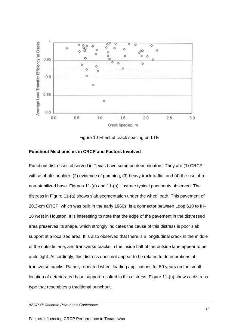
support. Figure 12-(a) shows the initial stage of punchout distress, and in order to identify
the cause of this distress, deflection testing with FWD was conducted at a 3-m interval. This
pavement section, 20.3-cm CRCP on asphalt stabilized base on IH-45 in Dallas was
completed in 1975. When the evaluation was made, the pavement was already 35 years old.
The testing results are shown in Figure 12-(b), which illustrates poor slab support at the
location of the distress. LTE values were evaluated at two transverse cracks (LTE 3-1 and
LTE 3-2 in the Figure 12-(a)) and the values were near 100 percent. Dynamic cone
ASCP 4th Concrete Pavements Conference 17
Factors Influencing CRCP Performance in Texas, Won
penetrometer testing was also conducted, and average back-calculated modulus values at
locations of no distress was 1,730 MPa, while the value at the middle of initial punchout area
was 1,261 MPa, which clearly explains the mechanism of this distress.
Figure 12-(a) Initial stage of punchout Figure 12-(b) Deflections along PO area
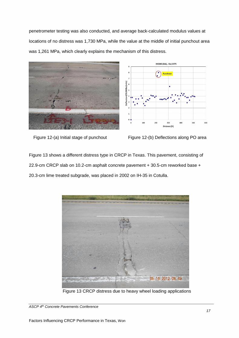
Figure 13 shows a different distress type in CRCP in Texas. This pavement, consisting of
22.9-cm CRCP slab on 10.2-cm asphalt concrete pavement + 30.5-cm reworked base +
20.3-cm lime treated subgrade, was placed in 2002 on IH-35 in Cotulla.
Figure 13 CRCP distress due to heavy wheel loading applications

ASCP 4th Concrete Pavements Conference 18
Factors Influencing CRCP Performance in Texas, Won
The distress shown in Figure 13 is different from a traditional punchout, since no evidence of
edge pumping or slab depression is observed. Forensic investigations were conducted and
the concrete segmentation was confined at the top half of the slab. The bottom concrete was
solid. Since there were no distresses in the inside lane, it was postulated that this distress
was related to heavy wheel loading applications. Traffic data on this section was obtained
from the weigh-in-motion (WIM) station located in this section. Figures 14-(a) and 14-(b)
illustrate single and tandem axle truck traffic applications in 2007 and 2011, respectively. In
Texas, the legal weight limit of single axle load is 20-kips (89 kilo-newton) and that for
tandem axle load is 34-kips (151 kilo-newton).
Figure 14-(a) Single axle load distribution Figure 14-(b) Tandem axle load distribution
Figures 14-(a) and 14-(b) show the applications of weights that far exceeded legal weight
limits. Structural responses of CRCP on the application of overweight axles were
investigated by analysing CRCP systems with a 3-dimensional finite element program as a
part of the development of the mechanistic-empirical CRCP design program for TxDOT (Ha,
et al, 2012). Figure 15 illustrates the analysis results for 40 kilo-newton wheel loading
application near a transverse crack. Maximum principal stresses at the top or bottom of
concrete slabs near transverse cracks are much smaller than those in the concrete
surrounding longitudinal steel. It is also interesting to note that crack stiffness does not have
substantial effects of wheel load stress at the top or bottom of the slab, while principal
stresses in concrete around longitudinal steel are affected. The analysis results imply that

ASCP 4th Concrete Pavements Conference 19
Factors Influencing CRCP Performance in Texas, Won
the interactions between longitudinal steel and surrounding concrete are significant, resulting
in large concrete stresses near longitudinal steel, and if excessive, the large concrete
stresses could cause cracks near longitudinal steel in the form of horizontal cracking and
ultimately segmentation of concrete slab as shown in Figure 13. Lately, CRCP distresses as
shown in Figure 13 were more frequently observed in Texas than in the past. Applications of
illegally overweight trucks are considered as a cause for those distresses. A new technology
called fracking has been implemented in Texas to extract oil and natural gas that previously
were locked away in shale and other tight-rock formations. This technology requires
enormous amounts of water and other materials, and hauling them to the job site
economically appears to be responsible for the applications of illegal overweight trucks. The
distress type shown in Figure 13 is relatively new, and increasing slab thickness/changing
the depth of the longitudinal steel could provide a solution to this problem.
Figure 15 Concrete stresses at various depths near a transverse crack
Another type of distress observed in CRCP is shown in Figure 16. These distresses occur at
the transverse construction joints (TCJ). The frequency of this distress type is not high;
however, since distresses due to structural deficiency of CRCP system are quite rare in
10-2
100
102
104
106
108
1010
0
50
100
150
200
250
Around the longitudinal steel
At the top of the slab
At the bottom of the slab
Crack Stiffness (psi/in.)
Ma
xim
um
Pri
ncip
al S
tre
ss (
psi)

ASCP 4th Concrete Pavements Conference 20
Factors Influencing CRCP Performance in Texas, Won
Texas, other than those due to poor slab support or illegal overweight truck applications, and
distresses in TCJ could occur at relatively early ages of pavement, TxDOT sponsored a
research study to identify the mechanisms of this distress type.
Figure 16 Distresses at transverse construction joints
Extensive evaluations of CRCP behaviour at TCJ, including stresses at longitudinal steel
and concrete strains and displacements at TCJ, indicated that the structural responses of
longitudinal steel and concrete were not excessive. Instead, the construction practices,
which includes dumping excess concrete mortar collected on the sides of the pavement into
TCJ or improper vibration in the morning side of the TCJ, were considered as a potential
cause for the distress.
Another significant distress type has been major spalling as shown in Figure 17. Major
problems with severe spalling include the degradation of ride quality, and potential safety
hazard. Severe spalling in CRCP was a major issue in Texas since the early 1980s. A
number of research studies were conducted over 30 years, and the last study was
conducted in 2011 and 2012, which revealed an excellent correlation between CTE of
coarse aggregate used and the potential for severe spalling (Ryu, et al, 2012). Sections with
severe spalling and no spalling were identified, and concrete material properties were
evaluated from cores taken from those sections. The concrete material properties evaluated

ASCP 4th Concrete Pavements Conference 21
Factors Influencing CRCP Performance in Texas, Won
included modulus of elasticity and CTE. The correlation between concrete modulus and
severe spalling was not as good as that between CTE and severe spalling.
Figure 17 Severe spalling in CRCP in Texas CTE values of concrete from sections with no spalling problems were lower than 9.9
microstrains/°C, while those from sections with severe spalling problems were larger than
9.9 microstrains/°C. Based on the research finding, TxDOT included CTE as a requirement
for coarse aggregate property that should be met if the coarse aggregate would be used for
CRCP. In Texas, crushed limestone (LS) and siliceous river gravel (SRG) are the two major
coarse aggregate types used in PCC pavement construction. Crushed limestone is of
angular shape and has a rough surface texture, which is believed to provide better bonding
between the coarse aggregate and surrounding mortar. On the other hand, SRG is of round
shape and has quite a slick surface, which does not promote good interfacial bonding
between coarse aggregate and the surrounding mortar. Measurements of mechanical
properties of concretes made with those two coarse aggregate types reveal that concrete
with LS has lower modulus and CTE values than concrete containing SRG (Won, 2005). As
discussed earlier, in CRCP, concrete volume changes due to temperature and moisture
variations are severely restrained by longitudinal reinforcement, and larger CTE and
modulus values of concrete with SRG, along with lower interfacial bond strength, are
believed to be responsible for severe spalling distresses for CRCP containing SRG as a

ASCP 4th Concrete Pavements Conference 22
Factors Influencing CRCP Performance in Texas, Won
coarse aggregate. It is interesting to note that spalling is not an issue in JPCP containing
SRG. It is because in JPCP, concrete volume changes due to temperature and moisture
variations are not restrained as much as in CRCP, and the resulting bond stresses at the
interfaces between coarse aggregates and surrounding mortar are kept to a minimum.
The role of longitudinal reinforcement in CRCP is to restrain concrete volume changes due
to temperature and moisture variations, which cause transverse cracks, and to keep
transverse cracks tight so that the continuity of the slab is provided. Accordingly, the amount
of longitudinal steel has effects on CRCP behaviour. Traditionally, the ratio of the steel
cross-sectional area to concrete area of 0.6 % to 0.7 % has been used. In 1989 and 1990,
TxDOT constructed test sections in 3 different projects to investigate the effects of
longitudinal steel amounts, coarse aggregate types, and concrete placement temperatures
on CRCP behaviour and performance (Suh, 1993). In Figure 18, the inside 2 lanes were built
with SRG as the coarse aggregate, while the concrete in the outside lane has LS as the
coarse aggregate. The marked difference in performance in terms of spalling is observed.
Figure 18 Effect of coarse aggregate type on spalling
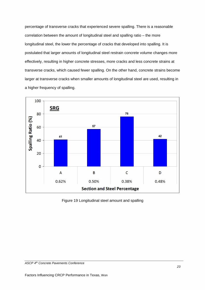
Also, three different steel amounts (0.38 %, 0.50 % and 0.62 % with 19.1-mm bars) were
used. Additional section was built at 0.48 % with 22.2-mm bars. Figure 19 shows the
ASCP 4th Concrete Pavements Conference 23
Factors Influencing CRCP Performance in Texas, Won
percentage of transverse cracks that experienced severe spalling. There is a reasonable
correlation between the amount of longitudinal steel and spalling ratio – the more
longitudinal steel, the lower the percentage of cracks that developed into spalling. It is
postulated that larger amounts of longitudinal steel restrain concrete volume changes more
effectively, resulting in higher concrete stresses, more cracks and less concrete strains at
transverse cracks, which caused fewer spalling. On the other hand, concrete strains become
larger at transverse cracks when smaller amounts of longitudinal steel are used, resulting in
a higher frequency of spalling.
Figure 19 Longitudinal steel amount and spalling

ASCP 4th Concrete Pavements Conference 24
Factors Influencing CRCP Performance in Texas, Won
Acknowledgements:
The technical discussions made in this paper were possible thanks to a number of
researchers as well as TxDOT staff engineers. Special thanks are made to the late Dr. B.
Frank McCullough, my mentor and supervising professor. This study was conducted under a
research project (Development of Eco-Friendly Pavements to Minimize Greenhouse Gas
Emissions) funded by the Ministry of Land, Infrastructure and Transport (MOLIT) and the
Korea Agency for Infrastructure Technology Advancement (KAIA). The author would like to
thank the members of the research team, MOLIT and KAIA for their guidance and support
throughout the project.
References:
1. American Association of State Highway and Transportation Officials, AASHTO Guide
for Design of Pavement Structures, American Association of State Highway and
Transportation Officials, Washington, D.C., 1993
2. ARA, Inc., ERES Division, Guide for Mechanistic-Empirical Design of New and
Rehabilitated Pavement Structures,” Final Report, Appendix LL, Champaign, Illinois,
2003
3. Choi, P.G., Ryu, S.W., W. Zhou, S. Saraf, Yeon, J.H., and Won, M., Project Level
Performance Database for Rigid Pavements in Texas, II, Research Report FHWA/TX-
14-0-6274-2, Texas Tech University, Lubbock, Texas, 2013
4. Ha, S.J, Yeon, J.H., Cho, B.H., Jung, Y.S., Zollinger, D.G., Wimsatt, A., and Won, M.
Develop Mechanistic-Empirical Design for CRCP, Research Report FHWA/TX-11-0-
5832-1, Texas Tech University, Lubbock, Texas, 2011
ASCP 4th Concrete Pavements Conference 25
Factors Influencing CRCP Performance in Texas, Won
5. Kohler, E.R., Experimental Mechanics of Crack Width in Full-Scale Sections of
Continuously Reinforced Concrete Pavements, Ph.D. Dissertation, University of Illinois,
Urbana Champaign, Illinois, 2005
6. Nam, J.H., Early-Age Behaviour of CRCP and Its Implications for Long-Term
Performance, Ph.D. Dissertation, The University of Texas at Austin, Austin, Texas, 2005
7. Ryu, S.W., Choi, P.G., Zhou, W., Saraf, S., Senadheera, S., Hu, J., Siddiqui, S., Fowler,
D., and Won, M. Optimizing Concrete Pavement Type Selection Based on Aggregate
Availability, Research Report FHWA/TX-12-0-6681-1, Texas Tech University, Lubbock,
Texas, 2012
8. Suh, Y.C., Hankins, K. & McCullough, B.F., Early-Age Behaviour of Continuously
Reinforced Concrete Pavement and Calibration of the Failure Prediction Model in the
CRCP-7 Program, Research Report 1244-3. Centre for Transportation Research, The
University of Texas at Austin, Austin, Texas, 1992
9. Tayabji, S.D., Selezneva, O, and Jiang Y.J, Preliminary Evaluation of LTPP
Continuously Reinforced Concrete (CRC) Pavement Test Section, Publication No
FHWA-RD-99-086, Federal Highway Administration, July 1999
10. Texas Department of Transportation, Condition of Texas Pavements – PMIS Annual
Report FY 2013 – 2016, Austin Texas, July 2016
11. Won, M. Improvements of Testing Procedures for Concrete Coefficient of Thermal
Expansion, Transportation Research Record 1919, Transportation Research Board,
National Research Council, Washington D.C., pp. 23-28., 2005