AUSTRALIAN ATOMIC ENERGY COMMISSION · AUSTRALIAN ATOMIC ENERGY COMMISSION RESEARCH ESTABLISHMENT...
27
o CN Ui AAEC/E204 uu AUSTRALIAN ATOMIC ENERGY COMMISSION RESEARCH ESTABLISHMENT LUCAS HEIGHTS CRYSTALLOGRAPHIC TECHNIQUES AND DATA FOR TRANSMISSION ELECTRON MICROSCOPY OF ZIRCONIUM by A. JOSTSONS J.G. NAPIER February 1970
Transcript of AUSTRALIAN ATOMIC ENERGY COMMISSION · AUSTRALIAN ATOMIC ENERGY COMMISSION RESEARCH ESTABLISHMENT...

oCNUi
AAEC/E204
uu
AUSTRALIAN ATOMIC ENERGY COMMISSIONRESEARCH ESTABLISHMENT
LUCAS HEIGHTS
CRYSTALLOGRAPHIC TECHNIQUES AND DATA FOR TRANSMISSION
ELECTRON MICROSCOPY OF ZIRCONIUM
by
A. JOSTSONS
J.G. NAPIER
February 1970
AUSTRALIAN ATOMIC ENERGY COMMISSION
RESEARCH ESTABLISHMENT
LUCAS HEIGHTS
CRYSTALLOGRAPHIC TECHNIQUES AND DATA FOR TRANSMISSION
ELECTRON MICROSCOPY OF ZIRCONIUM
by
A, JOSTSONS
J. G.NAPIER
ABSTRACT
The crystallography of hexagonal close packed metals is discussed briefly in termsof the four-axis hexagonal reference basis and the Miller-Bravais notation which are usedthroughout the report. Electron diffraction problems are treated with reference to the four-axis hexagonal reciprocal lattice rather than the more usual three-axis hexagonal system.Using these concepts, analysis of el?,:trou diffraction spot andKikuchi patterns is illustratedand applied to orientation and dislocation Burgers vector determinations. Computed values ofinterplanar spacings, interplanar angles, angles between directions, and extinction distancesfor zirconium are listed.

CONTENTS
Page
1. INTRODUCTION 1
2. CRYSTALLOGRAPHY OF h.c.p. METALS 1
2.1 Crystal Structure 12.2 Crystallographic Indices 22.3 Stereographic Projections 42.4 Dislocations in h.c.p. Metals 4
3. ELECTRON MICROSCOPY OF h.c.p. METALS 5
3.1 The Reciprocal Lattice 53.2 Electron Diffraction Patterns 73.3 Kikuchi Patterns 93.4 Determination of Dislocation Burgers Vectors 12
4. REFERENCES 14
APPENDIX 1 Interplanar Spacings in a-Zirconium
APPENDIX 2 Angles Between Crystallographic Planes in Alpha Zirconium, c/a = 1.593
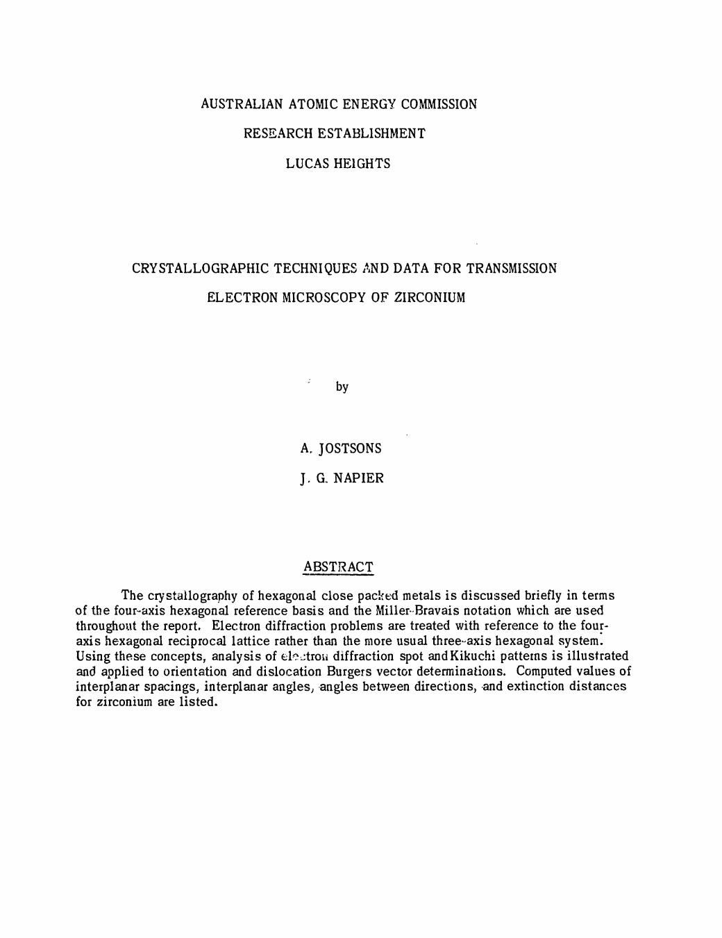
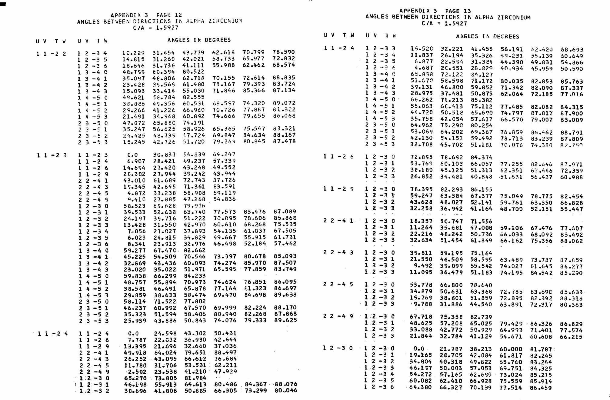
APPENDIX 3 Angles Between Directions in Alpha Zirconium, c/a- =1.5927
APPENDIX 4 Standard (0001) Projection for h.c.p. Zirconium
APPENDIX 5 Crystallographic Formulae for h.c.p. Metals
APPENDIX 6 Electron Diffraction Patterns Frequently Obtained from h.c.p, Metals
APPENDIX 7 Kikuchi Patterns
APPENDIX 8 Values of g.b. for Eight Reflections and^ <1120> -, ^ <1123> -, and
<0001> - Type Burgers Vectors
APPENDIX 9 Extinction Distances for Various Reflections for 100 kV Electrons in a-Zirconium
Figure 1 Model of hexagonal close-packed structure with unit cell shown in heavy outline.
Figure 2 Interstitial voids in the h.c.p. structure with ideal axial ratio c/a = 1 8/3.(a) Octahedral voids; (b) Tetrahedral voids. (Barrett and Massalski 1966).
Figure 3 Model of hexagonal close-packing of spheres with octahedral and tetrahedralinterstitial sites, looking along the c-axis. (Gehman I960).
Figure 4 Indices of planes in hexagonal crystals. (Barrett and Massalski 1966).
Figure 5 Indices of directions in the hexagonal system with both three - and four - digit indices.The c-axis is normal to the plane of the drawing; a i ? a^ and as in h.c.p.- crystals are alongthe close-packed rows of atoms. (Barrett arid Massalski 1966).
(continued)

CONTENTS (continued) 1. INTRODUCTION
Figure 6 Burgers vectors in the hexagonal close-packed lattice. (Berghezan, Fourdeux andAmelinckx, 1961).
Figure 7 Ewald sphere construction in reciprocal lattice.
Figure 3 -Indexing an unknown diffraction pattern.
Figure 9 Alternative ways of indexing a diffraction pattern from a thin foil with the upward drawnnormal [ 12l3] parallel to the electron beam.
Figure 10 Stereo graphic projections of plane normals; (a) and (b) correspond to diffraction patternsin Figures 9(a) and 9(b) respectively. The broken lines show reflections which wouldappear on the diffraction pattern after tilting about [ 1010] in the sense given on theprojections.
Figure A7.1 The [0001] Kikuchi map for h.c.p. titanium (c/a = 1.588). All poles are indexed interms of directional indices.
Figure A7.2 (a) A Kikuchi pattern from zirconium, (b) Schematic drawing of centre lines of indexedKikuchi pairs in (a).
Figure A7.3 An enlarged section of the [0001] standard projection for directions for h.c.p. zirconium.The foil orientation in Figure A7.1 is shown at B.
Zirconium and most of its alloys of interest in nuclear power technology have hexagonalclose-packed (h.c.p.) structure. Many aspects of physical metallurgical studies of these alloysrequire a knowledge of their crystallography which- in contrast to that of cubic metals, is notconsidered in any detail in the many available texts on physical metallurgy. Most of the scatteredinformation is in original papers in the literature and unfortunately some of them contain errorsbecause of confusion over different crystallographic systems and notation used to describe h.c.p.structures. An exception is the review prepared by Partridge (1967) but he does not list specificcrystallographic information such as values of interplanar angles and angles between directions forzirconium.
The aim of this report is to describe briefly the fundamentals of crystallography of h,c.p.metals and their application to problems in transmission electron microscopy of zirconium. Thespecific crystallographic formulae and data for zirconium required for quantitative electron microscopyhave been calculated and are tabulated in the Appendices. Some of these data have more generalapplication in X-ray diffraction studies and analyses of twinning and deformation modes in bulk mat-erials.
2. CRYSTALLOGRAPHY OF h.c.p. METALS
2.1 Crystal Structure
The arrangement of atoms in a h.c.p. metal can be shown in terms of a hexagonal prism,Figure 1, where the filled circles represent atom centres. The primitive unit cell, (heavy lines)
which does not immediately reveal the hexagonalsymmetry, has axes §! = a2 ^ c with the anglebetween aa and a2 equal to 120° and c perpendic-ular to both §1 and §2 . The unit cell contains twoatoms with positions given by the coordinates 000and 2- .L i. Sirice the surroundings of the interior
atom differ from those at the cell corners the atompositions in the h.c.p. structure do not constitute aspace lattice. The actual space lattice remains prim-itive with points at cell corners only if two atoms areconsidered to be associated with each lattice point.
If the atoms are considered as hard spheres,the plane containing both a* and a2 is a close-packedplane. The hexagonal close-packed structure is char-acterised by an ABABABA. ... stacking sequence ofclose-packed planes. In an ideal close-packed struc-ture the axial ratio c/a is equal to
Figure I. Model of hexagonal close-packed structure withunit ceii bhcwn in heavy outline. 1.633
Zirconium and its alloys have a strong affinity for hydrogen, oxygen, nitrogen and carbon whichin solid solution occupy : the interstitial holes. The locations of the octahedral and tetrahedral inter-stices in a h.c.p. structure are shown in Figure 2. There are 2 octahedral and 4 tetrahedral interstices
2. 1 7 ? 00 3 ^ 005per unit cell centred on coordinates ~ -2. ! , 1 2 land 2 i I
respectively. In an ideal h.c.p. structure of rigid spheres of radius r, the maximum radius of a spherethat can be accommodated in an octahedral or tetrahedral interstice is 0.41 r and 0.22 r respectively.The geometry of interstitial sites in a h.c.p. structure is revealed more clearly by the model shown inFigure 3.

-2- -3-
V5/2V?
Metal atoms
O Octahedral interstices
Metal atoms
O Tetrahedral interstices
(a) Octahedral voids (b) Tetrahedral voids
Figure 2. Interstitial voids in the h.c.p. structure with ideal axial ratio c/ft = N 8/3(Barrett and Massalski 1966)
TETRAHEORALINTERSTITIALS
OCTAHEDRALIMTERSTITIALS
Figure 3. Model of hexagonal close-packing of spheres with octahedraland tetrahedral interstitial sites, looking along the c-axis.
(Gehman i960)
2.2 Crystallographic Indices
Crystallographic indices constitute a convenient system of notation of crystal planes anddirections. The different axial systems commonly used to define the indices of directions andplanes in hexagonal crystals are three-axis hexagonal (Miller indices), four-axis hexagonal (Miller-Bravais indices) and orthohexagonal. Only the four-axis hexagonal system gives rise to similarindices for crystallographically equivalent directions and planes. This feature of the Miiier-Bravaissystem is an asset when dealing with typical problems in physical metallurgy, for example, descrip-tion of slip modes and Burgers vectors of dislocations, and accounts for its general acceptance. Themain arguments against universal use of the Miller-Bra vais notation are the alleged greater complexityof Crystallographic formulae and claims that the four-axis hexagonal reciprocal lattice is physicallymeaningless (Partridge and Gardiner 1967 a). The simplifications introduced by Nicholas (1966)
into Miller-Bravais formulae, however, lead to expressions of equal simplicity to those based on thealternative systems while still retaining the virtue of symmetry. Frank (1965), and more recently,Okamoto and Thomas (1967, 1968) have demonstrated that the four-axis hexagonal reciprocal lattice,though not strictly a reciprocal lattice according to the usual mathematical definitions, permits theanalysis of the necessary Crystallographic relationships directly in terms of Miller-Bravais indicesusing elementary vector analysis. Consequently, the four-axis hexagonal system with Miller-Bravaisindices does not introduce any additional limitations for normal electron microscopy, compared withalternative systems of indexing, -and is used throughout this report.
The nomenclature of planes in the Miller-Bravais system is shown in Figure 4 in which theprimitive hexagonal unit cell with the three axes,ai, a2 and a3 at 120° to each other in the basalplane, is shown within the hexagonal prism. Thus, •a three dimensional crystal is represented in fourdimensional space. From the symmetry of the axesin the basal plane it is noted that(1IOO)i I f~1Y"f (11*0)
I i a i i i i , ,. ,,.aa = -(§! + a.2) . (1)
Consequently, when reciprocal intercepts of aplane on all four axes are determined and reduced tothe smallest integers, the indices of a plane will beof the type (hki£), with the restriction that
(lOlO)
-o, h 4 k + i = 0 . (2)Figure 4. Indices of planes in hexagonal
crystals.(Barrett and Massalski 1966)
with the restriction that
u + v + t = 0
Similarly, an arbitrary crystal vector £ can bewritten in the form
= v§2 H- ta3 we. , (3)
(4)
•fa
The indexing of directions in the Miller-Bravais notation is illustrated in Figure 5 whera thetranslations leading from the origin to several lattice points are indicated. The comparatively unusual
translations used in deriving the indices of adirection are necessitated by the restrictionsimposed by Equation 4. The interplanar spaoings in h.c.p. metals are given by
«*_.!_
(5)
,2 -[010)
-dooi[lOlOj-(2101
[1120]-(HOI
Figure 5. indices of directions in the hexagonal system "with boththree—'and four—digit indices. The c-axis is normal to the planeof the drawing; a l f a2 and aa in h.c.p. crystals are along theclose-packed rows of atoms.
(Barrett and Massalski 1966)
where A? =~«j
The symbol A has been retained in the cry stalk-graphic formulae to conform with the literaturebut it is used later to denote the wavelength ofelectrons also, The meaning of these symbolswill be clear from the context.
Values of interplanar spacings of zircon-ium are tabulated in Appendix 1,

-4-
In the h.c.p. system, in contrast to the cubic system, a direction is not normal to a plane withthe same Miller-Bravais indices, except for directions of the form <000£> and <hkiO > . The indicesof the normal to a plane (hki2) are [ hki (AT 2 £)] .
Interplanar angles and angles between directions in h.c.p. metals depend on the c/a ratio andare tabulated for zirconium in Appendices 2 and 3 respectively.
2.3 Stereographic Projections
Although electron micrographs can be readily interpreted analytically, it is often more convenientto use Stereographic methods. Since directions in h.c.p. metals are not necessarily normal to planes ofthe same indices, -two Stereographic projections are required; one for plane normals (poles) and one forcrystal directions. Packer and Miller (1967) have demonstrated the application of two standard projec-tions printed on transparent film; one for poles and the other for directions; which when superimposedcorrectly permit the necessary operations. However Rarey et al. (1966) advocate the use of a doublestereogram' on which are plotted both the poles and directions with rational indices.
A stereogram in the standard (0001) projection is shown in Appendix 4.
2,,4 Dislocations in h.c.p. Metals
Since much of transmission electron microscopy is concerned with the study of dislocations,their geometry in h.c.p. metals will be considered. A notation based on the bipyramid shown in Figuie 6,devised by Berghezan et al. (1961), is often used to describe dislocations' in h.c.p. metals. Becausethe h.c.p. structure is a double lattice structure^ not all nearest neighbour atomic translations are poss-
ible Burgers vectors of perfect dislocations. Thetypes of dislocations which are likely to be stablehave been discussed by Frank and Nicholas (1953)and Berghezan et al. (1961) and are summarised inTable 1.
A comprehensive review of deformationmodes in h.c.p. metals has been made by Dornand Mitchell (1965). In zirconium the primaryslip mode is {1010} <1210> . There is verylittle unambiguous evidence for other slip systemsin zirconium, although basal plane slip of disloca-tions with ^-<^1120)> Burgers vectors has been
(a) «Jproposed to explain the formation of kink bands inzirconium deformed above 500°C (Reed Hill 1964).Martin and Reed-Hill (1964) have reported slipmarkings which could not be explained in terms ofthe above slip systems in grains of deformed poly-crystalline zirconium. Howe et al. (1962) suggestthe operation of slip on {1013} and {111!} planesfrom observation of slip traces in thin foils but theBurgers vectors of these dislocations were notidentified. There is no unambiguously proven casein zirconium of slip systems that will produce strainin a direction not contained in the basal plane, thatis, -dislocations with a Burgers vector with a non-
zero fourth index. However dislocations with a Burgers vector 4 <,1123> have been proposed by Rosen-
baum (1964) to explain atom movements associated with {1122} deformation twinning. The possibility ofslip iri<(ll23>directions is also suggested by analyses of deformation systems required to produce theobserved rolling textures in zirconium (Picklesimer 1966)0
-5-
TABLE 1
CD)
Figure 6« Burgers vectors in the hexagonalclose-packed lattice.
(Berghezan, Fourdeux and Amelinckx, 1961)
BURGERS VECTORS OF DISLOCATIONS IN h.c.p. METALS
Type of Dislocations(Figure 6)
Perfect dislocations
(1) AB, BC, CA, BAS CB, AC
(2) ST, TS
(3) 1ST ±AB, ±ST +BC, ±ST ±CA
Partial dislocations
(4) ±Ac7, ±Ba, ±Ccr
(5) ±crS, ±crT
(6) ±AS, ±BS, ±CS, ±AT, ±BT, ±CT
Total No. ofDislocations
6
2
12
6
4
12
Vector
J- 0.•^£1
±c
±£ + §i
±(3>-i + 3aJ i
± l c
(4) + (5)above
DirectionIndices of
Vector
•J-<H2D>
<0001>
A ./l-lTToV^ XAAA^/
§ <1010>
i<0001>
•~<2023>
Magnitudeof Vectorin Terms ofLatticeParameters
a
l e i
(a2 + c2)*
awI c l2
te' + c?)7
1-3 4 /
RelativeEnergies of)i sloe at ions
for c/a =1.633
a2
c' = f a'11 .T a'
i a2
3 a
-2- a'3 a
a2
Generally, the stability of various dislocations varies as the square of the Burgers vector as hasbeen assumed in values given in Table 1. This, however, is only approximately true in an isotropic med-ium. Theoretical analyses of dislocation stability after including effects of elastic anisotropy in zircon-ium have been made by Roy (1967). Fisher and Alfred (1968) and Yoo (1968). Apparently, basal and pris-matic slip of A <[1120)> dislocations is energetically equally probable and Roy (1967) suggests that theopredominant prismatic slip in zirconium may be due to the presence of interstitial impurities. Fisher andAlfred's calculations suggest that with increasing temperature, effects of elastic anisotropy render edgedislocations with b = -i- <ll20> energetically unstable in the basal plane.«5
The stacking fault energy of zirconium is high and it is expected that partial dislocations wouldnot be resolvable in the electron microscope.
3. ELECTRON MICROSCOPY OF h.c.p. METALS
3.1 The Reciprocal Lattice
For the interpretation of electron diffraction patterns the reciprocal lattice concept is the mostconvenient but some confusion in the literature is due to there being two alternative ways of defining thereciprocal lattice and the four index labelling of points (Frank 1965).
Mathematically the reciprocal lattice is defined by the following relationship between the recip-rocal lattice axes aj, a*, -ja* and the direct lattice axes a ± , a2 , a3:

-6- -7-
a?
a?
Y ( a 2 x a 3 )
§2)
(6)
where V is the volume of the unit cell in the direct lattice, that is, a t . a_2 x a3. This leads to their with 8:: = 1 when i = j and otherwise zero.
*(7)general relation a^ . a.j •
The reciprocal lattice is built up by repeated translations of the unit cell by the vectors £i,a2 and as.
Frank (1965), Otte and Crocker (1965). Partridge and Gardiner (1967) and Okamoto and Thomas(1967, 1968) have shown that the reciprocal lattice defined by Equation 6 leads to difficulties in thefour-axis hexagonal system using Miller-Bravais indices. The normal reciprocal lattice in hexagonalcrystals has ?xes at, a*, and c* which are related by Equations 6 and 7 to the axes a1? a2 and cin the three-axis hexagonal system with Miller indices. The angle between a? and a2 in this recip-rocal lattice is 60 ° and thus, because^they do not define a conventional hexagonal unit cell, 'theintroduction of a fourth axis a? = -(a* + a*) will not have the same geometrical significance as itsanalogue in the direct lattice. It is for this reason that the use of the three-axis hexagonal systemwith the Miller notation has been advocated for diffraction studies of hexagonal metals (Partridgeand Gardiner 1967). This procedure is unattractive because the symmetry of the hexagonal systemis not fully indicated and frequent transformation of indices is required if the end product of the cal-culation is to be Miller-Bravais indices.
The alternative approach, suggested by .Frank (1965). Otte and Crocker (1965) and developedin greater detail by Okamoto and Thomas (1967,1968) is to use a four-axis reciprocal lattice in whichthe introduction of the fourth axis has the same significance as in the direct lattice. The four-axishexagonal reciprocal lattice is constructed according to the alternative definition of a reciprocallattice, that is, a reciprocal lattice point hki£ lies at a distance from the origin which is the inverseof the spacing between (hki£) planes in the direct lattice, in a direction normal to^these planes. Thisdefinition of the reciprocal lattice is a corollary of the usual mathematical definition of a reciprocallattice. The reciprocal axes aj, a£, a*, c* are not related to the .direct lattice axes in the customaryway as defined by Equation 6 and do not satisfy the usual conditions of Equation 7. The reciprocallattice axes are parallel to the respective axes in the direct lattice. The mathematical relationshipsbetween the basis vectors in the four-axis hexagonal reciprocal lattice and the axes in the directlattice are given by:
a?
n*a.2
at
- U a> §,1
(8)
It is obvious, that in the four-axis hexagonal reciprocal lattice the following restrictions apply:
.*al)and
h + k + i = 0
(9)
Okamoto and Thomas (1967, 1968) have shown that only one out of every three reciprocal latticepoints in the four-axis reciprocal lattice coincides with a conventional (three-axis hexagonal) recip-rocal lattice point. However the additional points in the four-aids hexagonal reciprocal lattice havenon-integral indices and cannot represent real crystal planes. They can be considered to representreciprocal lattice points for which the structure factor is zero and hence will not be present in actualdiffraction patterns.
Although the four-axis hexagonal reciprocal lattice is not a true reciprocal lattice in the usualmathematical sense, the concept is most useful because it permits the calculation of necessary crystal-lographic relationships directly in terms of Miller-Bravais indices using elementary vector analysis. Forexample, the scalar product of a reciprocal lattice vector |hki£ and a direct lattice vector juvtw is givenby
= hu + kv + it + E w (10)
The direct lattice vector r_ is normal to the reciprocal lattice vector g when g.r = 0. This permitsthe determination of zonal relationships and invisibility criteria for dislocatiolis~directly in the Miller-Bravais notation.
Crystallographic relationships between crystal vectors and reciprocal lattice vectors in theMiller-Bravais notation have been derived by Otte and Crocker (1965, 1966), Nicholas (1966), Okamotoand Thomas (1968), Neumann (1966) and Schwartzkopff (1968). A summary of relationships useful intransmission electron microscopy is given in Appendix 5.
3.2 Electron Diffraction Patterns
Electron diffraction is interpreted most readily in terms of the reciprocal lattice and the Ewaldsphere construction (Kitsch et al. 1965). In Figure 7, consider the sphere of radius I/A. (the reciprocal
of the electron wavelength) that intersects theorigin of the reciprocal lattice at 0, wherecrystal planes spaced d^kig are inclined atan angle 6 to the incident electron beam alongEG. The reciprocal lattice vector ghki£ equalto OP will be on the sphere if ~~
.'Incident electronbeam
Sphere ofreflection
sin 9 - -QB- 1/dhkif _sin e ~ OE - 2A " (ID
Figure 7. Ewald sphere construction in reciprocal lattice
This relation is equivalent to Bragg' slaw. Thus, depending on the structure factor,a diffracted beam FP will arise whenever thereflecting sphere intersects a reciprocal latticepoint.
For electrons accelerated by 100 kVin the electron microscope, A.-* 0.037 A , theradius of the reflecting sphere is ~ 27 A" 'which is large compared with the lattice spac-ing of metals. The Bragg angles are also verysmall (about 1° ) and thus the reflecting spherecan be approximated to a plane over the visiblearea of the diffraction pattern. Consequently,if a plane in the reciprocal lattice is tangentialto the reflecting sphere, a simple ctoss-graiiagspot pattern will be formed. The normal to the
reciprocal lattice plane is a direct lattice vector t_ = [uvtw], the crystal zone axis, -which is parallel tothe direction of the incident electron beam. The indices of r can be determicollihear spots £1 =
determined from any two non-and gz = [h2k2i222] on the diffraction pattern since gi.r = g2.£ = 0.

-8-
Okamoto and Thomas (1968) have shown that in the four-axis hexagonal notation this leads to threesimultaneous equations:
gi .£ = hi.u
g 2 . £ = h 2 u
+ i i t + £ ± w = 0
+ i2 t + £ 2 w = 0
u + v + t = 0
(12)
which can be rearranged to give:
h ll2 —
W
w
1 = -£;w
\__w
w(13)
Jt_w
and using Cramer's rule the ratio u :v: t: w: can be solved to give:
r = [uvtw] = F2 k2 i2
o i i
hi £1 ii
h2 £2 i2
1 0 1 >
ht ki £±
h2 k2 £2
1 1 0 >
hi ki ii
h2 k 2 iz
1 1 1
(14)
Equation 14 contains a built-in symmetry check since the sum of the first three determinants must vanish.The indices of jr. represent the upward drawn normal to the diffraction pattern if £1 and £2 are chosen sothat an anticlockwise rotation of £1 through an angle less than 180 ° would bring the direction of gi intothe direction of £2«
Consider the stek s in indexing the electron diffraction pattern shown in Figure 8.
(i) Determine the interplanar spacings (d) of planesgiving rise to the spots Pi, P*, P3 on the diffractionpattern using the relationship
Jhki£ R (15)
Figure 8. Indexing an unknown diffraction pattern
where R is the distance of the spots from the originand XL is the camera constant obtained by calibra-tion of the electron microscope with a material ofknown lattice spacing.
(ii) Usually a set of indices hikiiiEi giving thecorrect value of d, can be assigned to gi providedthat not more than one crystallographically distinctset of such indices exists.
(iii) After assigning s specific set of indices to jji >there will still be many equivalent ways of indexing£3, corresponding to the multiplicity factor for theset of planeshjj-ksigEsk. The multiplicity factorsfor olanes in the h.c.o. system are listed below:
{hki£} = 24 , {hhii} = 12, {oki£| = 12, Ihkio} = 12,
{hhio} = 6, tokiol = 6, {ooo£} = 2.
Many of the permutations of indices o f h 3 k 3 i 3 £ 3 may lead to results which are not distinguishablecrystallographically and a correct set can be chosen by measuring the angle between gi and g3andcomparing the results with tables of interplanar angles in conjunction with a standard~projection ofplane normals.
(iv) Once two points on the diffraction pattern have been indexed consistently, all other pointscan be indexed by simple vector addition, for example,
[ h 2 k 2 i 2 £ 2 ] [ h s k s i 3 £ 3 ] .
(v) When the indices of two reciprocal lattice vectors gi and £2 are known, the normal to thecross grating pattern, that is, the zone axis of the crystal parallel tolhe directions of the incidentelectron beam, can be obtained using Equations 12 and 14. The sense of the direction of the normalto the diffraction pattern in the usual right-handed system of axes can be obtained using the conventionstated previously or by inspection using a double stereogram.
(vi) It must be noted that even if the sense of the normal to the diffraction pattern is known,there is still an ambiguity in indexing corresponding to a rotation of 180 ° about the normal to the foil.This ambiguity arises from the arbitrary assignment of the sign of the diffraction vector i in step (ii)above and can lead to erroneous results in some studies. This ambiguity can be removed by analysingthe Kikuchi pattern (to be considered in the next section) or by noting the effect of an applied tilt asillustrated in the following example. Consider a diffraction pattern with the upward drawn normal givenby [1213] . Such a pattern can be indexed in two ways as shown in Figures 9(a) and 9(b). The cor-responding stereographic projections of plane normals giving the crystal orientation are shown in Fig-ures 10(a) and 10(b) respectively. The correct indexing can be obtained by distinguishing the effectsof tilting the crystal about [lOlO] in the sense indicated on Figures 10(a) and.lO(b). A tilt of 19°would bring the crystal into an orientation such that spots corresponding to Oll2, 1102 and 1214 wouldappear on the diffraction pattern if the crystal orientation assumed in Figure 10(a) is correct. Other-wise, a crystal tilt of 14 ° would have caused reflections 0221, 2201 and f 2lf to appear as implied byFigure 10(b) which corresponds to the indexing assumed in Figure 9(b). It is important to realise thatthe alternative methods of indexing can lead to a deduction of opposite sense of inclination of planesin the [0001] zone for example.
It is often convenient to have available examples of indexed single crystal electron diffractionpatterns to aid the identification of unknown patterns on the microscope screen by simple inspection.A number of the most commonly bccurring diffraction patterns from h.c.p. crystals, indexed systematic-ally in terms of Miller-Bravais indices, have been published by Partridge (1967) and Partridge andGardiner (1967 b) and are reproduced with some variations in Appendix 6.
In h.c.p. crystals, the structure factor becomes zero and there is no diffracted beam when(h + 2k) is a multiple of 3 and £ is odd, for example 1121, 3033 etc. These conditions, however, arerelaxed for electron diffraction where extra spots may arise as a result of double difiraction, forexample "forbidden" spots 0001 may arise from double diffraction involving reflections lOll and1010. Spots due to double diffraction have been differentiated from the normal spots with non-zerostructure factors in the diffraction patterns shown in Appendix 6.
3.3 Kikuchi Patterns
A most useful method of determining the crystal orientation involves the analysis of Kikuchipatterns associated with the spots in electron diffraction patterns. A Kikuchi pattern is formed as aresult of Bragg diffraction of electrons which have suffered inelastic collisions involving only a smallenergy loss. The inelastic scattering provides the main component of the background intensity of thediffraction pattern. The Bragg scattered inelastic electrons, which form cones with the normal to thereflecting planes as axis, intersect the photographic plate in hyperbolae which under the geometrical

-II-
-10-
conditions in the electron microscope can be considered as nearly straight lines. Each set of planesgives rise to two parallel lines in a direction perpendicular to the projection of j^; the line separationR is given by ~~
IghkiER
(16)
1512
* • • Xiloi oin
tola 00*00 Toiott • • x
oifi TioT• • •
1215
(a)
1212K • • X
JlOl Olfl
50*0 0000 1010
01119 •
>212
(b)
Figure 9. Alternative ways of indexing z d i f fract ion pattern from a thin foilwith the upward drawn normal 11213] parallel to the electron beam
(OtH)
Figure 10. Stenographic projections of plane normals; (a) and (b) correspond to diffractionpatterns in Figures 9(a) and 9(b) respectively. The broken lines show reflectionswhich would appear on the diffraction pattern after tilting about [lOlO] in the sensegiven on the projections
where XL is the camera constant. The angular separation of the lines is thus 2 6 and the lines aresituated symmetrically on either side of the trace of the reflecting plane. This property leads to animportant difference in behaviour between the Kikuchi lines and the normal spot pattern when thespecimen is tilted. The spot pattern does not move on tilting over a small angular range, but theindividual spots change in intensity; some spots disappear and others appear in different positions.On the other hand, the Kikuchi lines move as though rigidly fixed to the crystal, so that their direc-tion and magnitude of movement reveals the orientation change with high accuracy. The determinationof accurate orientations from Kikuchi patterns will be considered in this section.
Let us consider first, however, the limitations inherent in electron diffraction spot patternsfor accurate orientation determinations.
(i) Because of the extension of reciprocal lattice points into iclrods, reflections canremain unchanged over a large angular range of tilt (±5°) leading to errors of atleast this order of magnitude in the determined orientations. In very thin foi!s>spot patterns become complicated because second-Laue-layer relrods intersectthe reflecting sphere.
(ii) A symmetrical diffraction pattern may be obtained from foils in non-symmetricalorientations as a result of foil buckling.
(iii) Perhaps the most important limitation in diffraction studies is the need to usetwo-beam conditions. It is not possible, of course, to determine an accurateorientation from one diffracted beam.
The indexing and application of Kikuchi patterns in orientation determinations is well coveredin the text by Hirsch et al. (1965) and the papers by von Heimendahl et al. (1964) and Otte et al. (1964).The application of Kikuchi methods to h.c,p, metals has been discussed by Okamoto et al. (1967) andOkamoto and Thomas (1968). The essential features are discussed here.
The initial step in orientation determination is the identification of Kikuchi lines from measure-ments of the pair separation, whereby dhki£ derived using Equation 16 is compared with values of inter-planar spacings for the material studied. Ambiguities in indexing Kikuchi pairs with very similar sep-aration can be avoided by comparison of measured angles between, different sets of Kikuchi pairs withinterplanar angles between the sets of planes responsible for the Kikuchi lines.
The intersection of the centre lines of different pairs of Kikuchi lines, the Kikuchi pole,corresponds to a crystal zone axis containing the planes giving rise to the Kikuchi lines. The indicesof the zone axis can be obtained by substitution in Equation 12 and 14 of indices of the intersecting setof Kikuchi pairs. Thus, when a Kikuchi pole is located at the origin of the diffraction pattern theorientation is determined accurately.
The most common situation, however, is one where the Kikuchi poles are not located on theorigin of the diffraction pattern. Then the orientation is determined by indexing three non-parallelKikuchi pairs and the Kikuchi poles of their intersections (von Heimendahl et al. 1964). The orienta-tion is then obtained from angles subtended between these poles and the origin of the diffraction pattern,either by calculation or stereographic projection. Since Kikuchi poles are zone axes in the crystal,that is, directions, a standard stereographic projection of directions must be employed for hexagonalmetals. The method of orientation determination using two Kikuchi poles has been discussed by Otteet al. (1964).

-12-
Okamoto et al. (1967) and Okaraoto and Thomas (1968) have constructed composite Kikuchi mapswhich cover a significant region of reciprocal space. These maps enable unknown Kikuchi patterns tobe solved quickly even when they do not contain two Kikuchi poles. The detailed geometry of thesemaps for h.c.p. metals depends on the c/a ratio. Okamoto and Thomas (1968) have constructed a Kikuchimap for titanium (c/a = 1.588) which is reproduced in Appendix 7 and should be applicable to zirconiumwhere c/a = 1.593.
Although Kikuchi patterns can be constructed for various orientations, the curvature of Kikuchilines gives rise to difficulties if large angular ranges are required. The most satisfactory solution,according to Hirsch et al. (1965), is to present a large angle plot as a stenographic projection of plasetraces, that is, the centre lines of Kikuchi pairs.
In conclusion, it is emphasised that because a Kikuchi pattern is uniquely representative ofcrystal symmetry the 180° ambiguity in orientation determination, which arises from the arbitrary assign-ment of the sign of the diffraction vector £ in electron diffraction patterns, is not present in orientationsdetermined from Kikuchi patterns.
3.4 Determination of Dislocation Burgers Vectors
Contrast in transmission electron microscope images of crystalline materials arises mainly fromBragg scattering cf the incident electron beam. In bright field microscopy a small aperture is insertedin the objective lens so that diffracted electrons are blocked out and only the undeviated electrons arepermitted to form the image. Thus, dark regions in the image correspond to regions of the thin foil whichare favourably oriented to give strong diffracted beams. The interpretation of bright field contrast is fac-ilitated if only one diffracted beam is operating, that is, the 'two-beam' case of one undeviated beam anda diffracted beam. The two-beam theory of dislocation image contrast is presented in detail in the textby Hirsch et al. (1955).
The usual method of Burgers vector determination makes use of the invisibility criteria. Thusa perfect screw dislocation, which produces atomic displacements in the direction of the Burgers vector,will be invisible, in an elastically isotropic material, if the condition £ . b * 0 is satisfied, where g isthe diffracting vector and b is the Burgers vector of the dislocation. This, of course, is a general prin-ciple stating that displacements or lattice distortions parallel to the reflecting plane produce no contrast.Similarly, an edge dislocation will be nearly invisible if £. b^= 0 although some residual contrast may beobserved because a pure edge dislocation produces minor atomic displacements perpendicular to t) . Thecondition for exact invisibility for a perfect edge dislocationis given by £. b = 0 together with g.bx u ^0,where £ is a unit vector along the dislocation line. For mixed dislocations some contrast is expectedunder all two-beam conditions, but it is found (Hirsch et al- 1965) that dislocations are effectively invisibleif £ . b^ = 0, and if £ . _b x u < 0.64 . At higher values of ^ - b.x u some contrast is expected.
The above account of the invisibility criteria is adequate for materials which are elastically iso-tropic. Head et al. (1967) and Humble (1967) have demonstrated that as the degree of elastic anisotropyis increased, the residual contrast associated with the condition g. b = 0 and g, . b x u_ = 0 generally,tends to increase. In practice, thus, ''near invisibility' is generally accepted as corresponding to thecondition = 0.
The degree of elastic anisotropy in h.c.p. crystals cannot be described by a single parameter asin cubic crystals. For a h.c.p. metal to be elastically isotropic, 'the following three ratios must be sim-ultaneously equal to unity:
A = 2C44/(Cll-Ci2) = C44/C66
B = Cas/Cn
•13
Fisher and Alfred (1968) showed that for zirconium at 300 °K, A = 0.907, B = 1.149, C = 1.115 whereasat 1133 °K the ratios are 2.00, 1.292 and 1.281 respectively. Thus, at room temperature elastic isotropyappears to be a reasonable approximation for zirconium and should permit the determination of the con-dition . b> = 0 from observations of 'near-invisibility'.
-13-
The unambiguous determination of J> requires two values of g which correspond to the conditiong . b = 0. The Burgers vector is then parallel to the direction which'is common to these two reflectingplanes, that is, £1 x g^ . The indices of b^ in the Miller-Bravais notation are obtained by solving Equa-tions 12 and 14. ~~ "~
Values of j* . b^ for perfect dislocations in h.c.p. metals with various low Border reflections havebeen tabulated by Partridge (1967) and are reproduced, with the addition of the 1124 reflection, inAppendix 8. Using these values of g . b,. the fraction of perfect dislocations visible for any of the low-order reflections included in Appendix 8 can be deduced and are shown in Table 2. The values shownin Table 2 are based on the assumptions:
(a) all Burgers vectors of similar form are equally represented.
(b) dislocations are visible only when g . t) / 0.
TABLE 2
THE FRACTION OF PERFECT DISLOCATIONS VISIBLE IN H.C.P. METALS
(ASSUMING ALL BURGERS VECTORS OF A FORM ARE EQUALLY REPRESENTED)
Reflection
10TO
0002
lOll
1012
1013
1120
1122
1124
Fraction of dislocation visible
J <1120>
2/3
0
2/3
2/3
2/3
1
1
1
J <1123>
2/3 '
1
2/3
1
1
1i
5/6
1
< 0001>
0
1
1
1
1
0
11
In addition to uncertainties introduced in bright-field image analysis of Burgers vectors inmaterials exhibiting elastic anisotropy, France and Loretto (1968) have demonstrated that undercertain two-beam conditions dislocations are predicted to be invisible when jg . b / 0. These calcula-tions have been supported by observation. This behaviour is connected with large values of w, thedeviation parameter in the dynamical theory (Hirsch et al. 1965) which are usually associated withlarge diffr? tion vectors.
To avoid errors in the determination of Burgers vectors of dislocations, the observed brightfield images should be compared with calculated images which take into full account the foil, dis-location and diffraction geometry under which the observations were made. Head (1967) has developeda method of computer calculation of theoretical images as pictures taking into account elastic aniso-tropy. This technique has been generalised by Humble (1968) for the case of a dislocation in a tiltedfoil. An important parameter in these calculations is the extinction distance corresponding to thevarious diffraction vectors used. Extinction distances for the common reflections in zirconium havebeen computed and are listed in Appendix 9.

-14-
4. REFERENCES
Barret, C.S. and Massalski. T. B. (1966). - Structure of Matals, 3rd ed., McGraw-Hill, New York.
Berghezan, A., Fourdeux, A., and Amelinckx. S. (1961). - Acta Met. _9: 464.
Dora. J.E. and Mitchell, J.B. (1965). - High Strength Materials, p.510 (V.F. Zackay editor)
J. Wiley, New York.
Fisher, E,S. and Alfred, L.C.R. (1968). - Trans. Met. Soc. AIME 242: 1575.
France, L.K. and Loretto, M.H. (1968). - Proc. Roy. Soc. A307: 83.
Frank. F.C. (1965). - Acta Cryst 18: 862.
Frank, F.C. and Nicholas, J.F. (1953). - Phil. Mag.^4: 1213.
Gehman, W.G. (1960). - NAA - SR - 6003.
Head, A.K. (1967). - Aust. J. Phys. 20: 557.
Head, :A.K., Loretto., M.H. and Humble, P. (1967). - Phys. Stat Sol. 20 : 505.
Hirsch, P.B., Howie, A.. Nicholson, R.B., Pashley, D.W. and Whelan, M.J. (1965). - ElectronMicroscopy of Thin Crystals, Butterworths, London.
Howe, L.M., Whitton, J.L. and McGurn, J.F. (1962). - Acta Met. 10: 773.
Humble, P. (1967). - Phys. Stat. Sol. 21: 733.
Humble, P. (1968). - Aust. J. Phys. 21: 325.
Martin, J.L. and Reed-Hill, R.E. (1964). - Trans. Met. Soc. AIME 230: 780.
Neumann, P. (1966). - Phys. Stat. Sol. 17: K71.
Nicholas, J.F. (1966). - Acta Cryst. 21: 880.
Okamoto, P.R. and Thomas, G. (1967). - Scripta Met. I: 25.
Okamoto, P.R. and Thomas, G. (1968). - Phys. Stat. Sol. 25: 81.
Okamcto, P.R., Levine. E. and Thomas, G. (1967). - J. Appl. Phys. 38: 289.
Otte, H.M. and Crocker. A,G. (1965). - PhySc Stat. Sol. 16: K25.
Otte, H.M. and Crocker, A.G. (1966). - Phys. Stat. Sol. 16 : K25.
Otte, H.M., Dash, J, and Schaake, H.F. (1964). - Phys. Stat. Sol._5: 527.
Packer, M.E. and Miller, D.R. (1967). - J. Australian Inst. Met. 12: 299
Partridge, P.G. (?u967). - Met. Reviews J18: 169.
Partridge, P.G. and Gardiner, R.W. (1967a). - Acta Met. 15: 387.
Partridge, P.G. and Gardiner, R.W. (1967 b). - Scripta Met. 1: 139.
-15-
Picklesimer; M.L-. (1966). - Electrochem Tech. 4j 289.
Earey, C.RV Stringer, J. and Edington, J.W. (1966). - Trans. Met. Soc. AIME 236: 811.
Reed-Hill., R.E. (1964). - Deformation Twinning p. 295 (Reed-HilL R.E., Hirth, J.P. and Rogers, H.C.editors), Gordon and Breach. New York.
Rosenbaum, H.S. (1964). - Deformation Twinning p,s3 (Reed-Hill, R.E., Hirth, J.P. ana Rogers. H.C.editors). Gordon and Breach; New York.
Roy; R.B. (1967), - Phil. Mag. 15: 477.
Schwartzkopff. K. (1968). - Scripta Met. 2_: 227.
Smith, G.H. and Burge, R.E. (1962). - Acta Cryst. IS: 182.
von Heimendahl, M., Bell, W. and Thomas, G. (1964). - J. Appl. Phys. 35: 3614.
Yoo? M.H. (1968). ~ Scripta Met. ,2: 537.

APPENDIX 1
INTERPLANAR SPACINGS IN a-ZIRCONIUM
Interplanar spacings for a-zirconium, shown in the table below, were calculated from latti(parameters determined with powder X-ray methods on zone refined zirconium supplied by MaterialsResearch Corporation. The lattice parameters at 21 °C are:
a - 3.2330
c 5.1497
c/a = 1.5927
{hklEl
lOfO
0002
1011
10l2
1120
1013
2020
1122
2021
•000,4
2022
2023
1230
1231
d in A
2.7999
2.5749
2.4598
1.8953
1.6165
1..4634
1.3999
1,3691
1.3509
1.2874
1.2299
1.0849
1.0583
1.0366
{hkift
1124
1232
2024
3030
1233
3032
1234
2240
..
d in A
1.0071
0.9788
0.9476
0.9333
0.9008
0.8774
0.8175
0.8083

APPENDIX 2 PAGE 1ANGLES BETWEEN CRYSTALLOGRAPHIC PLANES IN ALPHA ZIRCCMUM
C/A = 1.5927
H K I L H K I L
0 0 0 1
I 0 -I
1 0 - 1 1
ANGLES IN DEGREES
c111II22331111.11111
"t.1,
1.II
22
311I111I11
111122331111111
CCCcccrCCc111112222
cCccrCCcc1111I2222
CCCCCCCC111112#*•
C-1
•*.
-2
_3— 2— 2-2-2•"" £iri -3
.3
**** A
-i— i
-"• 2
— 3-2
— 2-2_ ^.-3-2-2— 2
-i-1— •}-1-2
•5**•£
- 3-3-2-2-2•• 3
-?«3-3
r
2
4
312G1234C1
3
c1234
3I2C1234C123
12341312C12340i
C.9C.61.42.31.
74.5C.79.7Co9C.72.57.46.3B.9C.76.67.58.
0.28.47.56.65.15.39..V C. a
19.3C.34.42.5C.57.19.22.29.36.
0.18.29.36*13.1C.16.8.
40.29.26.28.32.33.24.
0oc466051
8C7307OC5788725300396634
053404931212G2793002882923511250846
08696773367266146660619048959
60.63.7C.74*77.61.67*60.61.9C.9C.9C.90.90.4C.42.45.49.
52.49.5C.51.43.5C.38.48.90.54.67.7C.68*48.41.
009422859415205396CO0000000089236495
1154448774G3814600350288C6397C
79.79.79.80.
57.75.79.75.56.67.58.54.
81.75.76.84.80.44*
11339374
O /94774969748485
772892244420
80.86.87.86.72.87.69.75.
56.
9389031663806951
33 75.00 86*19

APPENDIX 2 PAGE 2ANGLES BETWEEN CRYSTALLOGRAPHIC PLANES IN ALPHA ZIRCCNIUH
C/A = 1.5<527
H K I L
1 0 - 1 1
1 0 - 1 2
1 0 - 1 3
I 0
2 0 - 2 1
H K I ANGLES IN DEGREES
1 21 2
1 C1 01 C2 02 C3 C3 C1 11 11 11 11 1I 21 21 21 2
1 C1 C2 C2 C3 C3 01 11 11 11 11 11 21 21 21 2
1 C2 G2 C3 03 01 11 11 11 11 11 21 21 21 2
2 02 03 0
-3«3
-1-1-1— n
-2-3-3-2-2-2
*»
-2«. -3—3-3
-1-1-2-2-3-3-2-2-2-2-2-3-3-3— 3
-1•=» 2-2-3
**
*•* 2-2-2-2-2-.-a•«*
-3-3-3
-2-2.-3
23
2341312C12340123
34131201234C123
4i312012340123
131
18.16.
0.11.17.32.
6.37.27.54.38.27.21.19.5C.39.29.21.
0.6.
43.19.48.38.63.46.33.23.18.60.49.38.29.
0.50.26.55.45.68.51.37.27.20.66.55.44.35.
Ow23.4.
3080
0099119201347117639357824223845
08228292256095921934041056680
010110438798886595975287263
09994
37.35.
39.36.35.58.43.57.55.90.7C.66.59.54.59.49.41.34.
30.27.61.42.65.57.90.75.63.54.48.66,56.46.38.
24.63.42.68.59.90.74.61.51.44.71.60.50.41.
30.54.25.
2631
56448969326732002096698422511473
309059158557002104231773044140
1190604360GO2111477159514079
424148
54.62.
71.63.58.62.78.62.67.
77.83.85.77.82.61.66.6C.
53.48.73.70.68.78.
79.85.75.67.84.71.65.57.
42 «80.65.75.83.
85.79.68.60.85.74.65.57.
57.
1188
77211761293433
2697538465425432
822870357642
8399233633814589
4252645850
8182939647922604
7057.3458.56
64.66.
85.74.67.82.86.78.86.
69.71.73.
63.56.88.82.83.87.
74.76.68.
49.87.75o87.85.
78.74.65.
66.
3792
20112933603614
338489
022037319743
435469
3889495123
241982
62
70.42 88.3971.66 83.72
—
74.13 88.6978.85 80.7080.90 87.18
77.56 85.7182.38 87.6383.62 88.45
82.74 83.9486.94 88.8777.99 81.90
77.9964.66
APPENDIX 2 PAGE 3ANGLES BETWEEN CRYSTALLOGRAPHIC PLANES
C/A = 1.5927,<LPHA ZIRCONIUM
H K I L
2 0 - 2 1
2 0 - 2 3
3 0 - 3 1
3 0 - 3 2
1 1 -2 0
H K I ANGLES IK Dcb^EES
3 G1 11 11 11 11 11 21 21 21 2
2 03 03 01 11 11 11 11 11 21 2I 21 2
3 03 01 11 11 11 11 11 21 21 21 2
3 C1 1111 11 11 11 21 21 21 2
111111111 11 .21 2
— 3-2-2-2-2-2-3-3-3-3
-2-3-3-2-2-2-2-2-3-3-3-3
2012340123
3120123401?.i
4332832374324181923
02819473325222442322317
.72
.31
.85
.09
.98
.46
.24
.92
.42
.96
.0
.93
.28
.85
.94
.25
.80
.15
.93
.38
.43
.25
~" 1 0.0-3-2-2-2-2-2-3-3-3-3
-3-— 2>2-2-2-2-3-3-3—3
-2>2--2>2-2-3-3
2G12340123
2012340I23
0i2340 3
i
9312935424721182127
0352829343927201720
017324351j i<315
.65
.55
.95
.26
.05
.91
.60
.80
.91
.75
.0
.49«49.45.27.30.33.15.97.77
*0•43.12.28.47.89.87
35.1490.0044.0555.3764.6371.6243.1632.8239.2540.66
45.5949.4754.5790.0063.1970.3664.326C.3754.1445.4938.5533.87
20.5530.2090.0040.5751.1860.1366.9641.9428.9837.6143.39
^9.8590.0047.5759.4568.9674.5444.7136.7238.1138*39
60. UO£1.5164.9568.6571.85
• * 49i'ii50.11
57
85ei7978793941ec786059
7976868581536462
5858
8684828179404045
56
8479767679404654
t 70j <71
.11
.49
.98
.64,16.49.89.96.32
.40
.40
.13
.09
.57
.83
.62
.58
.84
.09
.85
.94
.45
.94
.56
.98
.98
.28
.14
.91
.75
.08
.14
.56;«49.08.77.12.20.74
.89;so •
68.
48.54.61.
OT»
74.81.
63.67.73.
63.66.
46.51.57.
70.
51.58.64.
64
579010
014244
4393-05
1131
166735
99
131578
76.6274.4372.97
74.2972.4578.05
77.4176.1375.41
75.9672.9170*73
82.7786.0586.99
89.0783.9880.39
81.5984.0286.29
-
83.95£8.0183.42
1

APPENDIX 2 PAGE 4ANGLES BETWEEN CRYSTALLOGRAPHIC PLANES ifc ALPHA ZIRCONIUM
C/A = 1.5927
H K I L
1 1 - 2 0
1 1 - 2 1
1 1 - 2 2
i 1 -2 3
1 1 - 2 4
1 2 - 3 0
1 2 - 3 1
1 2 -3 2
1 2 -3 3
H K I L ANGLES IN DEGREES
1 2I 2
I II II II II 2I 2I 2I 2
I II II II 2I 2I 2I 2
I II II 21 2I 2I 2
I II 2I 2I 2I 2
1 21 2I 21 2
1 2
1 2
1 2
1 2
1 2
1 2
— 3
-2-2-2-2-3-3-3-3
-2-2-2— 3-3-3-3
-2-2-3-3-3-3
-2-3-3— 3-3_3
«3M "2
-3
-3
*™ .j
— 3
-3
-3
-3
23
123
C123
23AC123
34C123
40123
C123
1
2
3
2
3
3
2433
C1425342C121117
01119332213
9
08
44332214
052
.74
.29
.0
.69
.85
.04
.46
.04
.36
.31
.0
.16
.34
.73
.83
.75
.26
.0
.18
.37
.05
.80
.46
.0
.2940*833021
0112231
C581C582058
058
965
067
.32
.37
.0
.61
.34
.66
.0
.65
.73
.03
.04
.50
.0
.15
.31
.22
.0
.73
52.56.
34.
56.57.51.30.41.46.
50.47.47.56.44.44.41.
42.40.61.52.45.40.
36.65.56.47.4C.
21.24.30.37.
21.63.23.67.28.71.
20.73.
7413
8655458935971846
11711833963632
692654784605
3093165874
79568178
349539893787
1355.
21.4771.
18.72.
82
51'91
72*3873.82
56.9955.726C.7168.9071. 8G47.7746.2550.19
64.2575.4161.2573.9149.4555.4659.00
78.1771.9776.2155.7961.2555.76
65.3078.2363.7960.9254.26
38.2139.6843.3948.02
23.2379.7733.9678.114C.4777.01
35.2574.5335.1078.81
32.3680.10
68.75.81.86.
56.62.64.
35.86.83.
64*62.64.
86.85.
. 68.66.75.
77.
69.74.76.
60.60.62.64.
31.84*37.86.43.89.
44.88.53.85.
50.85.
57838440
533797
657759
1571kl
5725
•203960
06
074329
00674581
744697972723
69726201
3802
68.5266.2568.01
67.7571.9078.88
70.8079.6280.97
76.0083.7583.68
81.7981.9682.4183.02
37,40
40.12
48.04
49.47
54.00
63.31
-
75.7879.9283.76
80.5386*8987.53
84.5387.6987.37
87.5885,4286.36
44.49
50.56
56.67
55.09
57.89
66.59
U V T a
0 0 0 1
APPENDIX 3 PAGE 1A N G L E S BETWEEN DIRECTIONS Ih ALPHA ZIRCC.NIUH
C/A * 1.5927
U V T .
0 0 C 11 0 - 1 01 0 - 1 1I 0 1-1 210-1 31 C -I 41-0-1 51 C -1 62 0 - 2 12 C -2 32 0 - 2 53 0 - 3 13 0 - 3 23 0 - 3 43 0 -3 54 0 - 4 14 C -4 31 1 - 2 01 1 - 2 1I 1-2 21 1 - 2 31 1-2 41 1 - 2 61 1 -2 92 2 - 4 12 2 *4 32 2 - 4 52 2 -4 91.2-3 01 2 -3 11 2 r3 21 2 - 3 31 2 -3 41 2 -3 51 2 -3 613 -4 01 3-4 113: --4 21 3 -4 31 :4 -5 0I :4 -5 11 4 ^5 214 : -5 32 3-5 0* 3 -5 12 3 -5 2t 3-5 3
0.090.00047.40028.53519.92515.21012.27110.27365.30835.94223.50972.95958.49039.20133.12477.05355.40890.00062.03643.28332.12325.21617.42911.82175.13451.46836.99622.71390.00070.83555.19643.80335.72829.91825.61990wOOO75.69262.97552.58090.00078.65468.13356.95390.00078.08867*12457.671
I 0 «l;o 1-0,-10
Wl 3
>-i ..5
ANGLES IN DEGREES
<JiO : 60.00042.600 68,405
80¥18974*790 82*462
83«SCO

U V T H
1 0 - 1 0
1 0 - 1 1
APPENDIX 3 PAGE 2ANGLES BETWEEN DIRECTIONS Ifc ALPHA ZIRCONIUM
C/A = 1.5927
U V AnGtES IN DEGREES U V T
10-1 62 0 - 2 12 0 - 2 32 6 - 2 53 0 - 3 13 6 - 3 23 0 - 3 43 0 -?3 54 0 - 4 14 0 - 4 3I 1 -2 011 -2 11 1 - 2 21 1-2 31 1 - 2 41 1 - 2 611 ~2 92 2 -4 I'I 2 - 4 32 2 - 4 52 2 -4 91 2 -3 012-3 I1 2-3 21 2 - 3 31 2 - 3 41 2 - 3 51 2 -3 61 3 - 4 01 3 - 4 I1 3-4 21 3-4 31 4 - 5 01 4 -5 11 4 -5 21 4 - 5 32 3 -5 02-31-5 i -2 3 -5 22 3-5 3_..10-1 11 0 -1 210-1 31 0 "•! 41 0-1 51:0-1 62 < 0" -2 1 :2 0 >2 32 0 - 2 53 0 - 3 13<0. -3 23 0 -3 43' a -3 5
79.7S724.69254.05866.49117.04131.51050.79956.87612.94734.59230.00040.10153.57662.58068.34974.96679.78133.1^7147.35558.59170.46519.10726.80639.U549.15256,51261.88265.88513.89819.84536*14839.56010.89315.67924.31032.72223.41326*11732.27639.157' •-• . . .0.0
18.86527*47532.19035*12937*12717.903
• ll*45823.89125*55911.0908.198
14*276
84.88462*98172.93378.49561*44264.76871.57774.14360.83765.69490.00090.00090.00090.00090.00090*00090.00090.00090.00090.00090.00040.89344.43651 -.63 258.45063.60667.85070.92246.10247-78851.85456.58649*107t50.06952.58755,88436*58738.21842.28547*274*• *43.29139.60440.37841.43442.30042.97451*892*0*ltf 9
• i
56.616' 48.12240*78639.826
79.10779.71781.07382.48483.66484*59185.31373.89874.41075.6967T.27570.89371.28172.31573.71483.41383.55683*933t
84.438; r ~ . *. .u .:
, . 79.20865.23959.27556.17854*32553.10367.292
, 7G,'01;1L';./•-f61.'i7-13 -
59.64174.10973*02868.546 -t
85.20075.93567.32562.61059.67157.67387.040$3.34270.90981*16987.70986.60180.524
1 0 - 1 1
1 0 - 1 2
U V V5,
** m %v - / A
i I irs
4 C4 C1 11 I1 11 11 11 I1 12 22 22 22 21 21 2I 21 21 21 21 21 31 31 31 31 41 41 41 42 32 32 32 3
1 G1 C1 01 01 C2 C2 02 03 03 C3 03 04 G4 01 11 i111 11 111X 1
-4«*.
-2-2-2-2-2-2-4
-4
-3— 3-2«3-3-3
—3-4-4-4-4-5-.5-5-5-5
— 5— 5-5
-1-1-1-1-1-2-2-2— 3-3-3~3«4-4-2-••2-2-2-2-2-2
3012346913590123456G12301230I23
234561351245130123469
S . G G f i
28.30421.59524.18527.87633»20337.52337.83323.02522.45029.48C45.92928.16.14.17.2C.24.44.30.
453772079129999345394722
19.25111.43.32.22.14.47.36.27.21.
0*8.
13.16.18.36.7.5.
44.29.1C.4.
46«26.65.38.22.15.13.15.19»
818711661642447508807689131
028609325264262773407026^424955666589518872563982605419819824154
5* <t •' *. £A A * • ^*.»*•.• • •>
46. 3d 6
71.4946C.47955.0235,1. 23 P
63.7 M?65.(V-f57.27^51.36356. ISC4! ,59^32.51729.11229.0253C.20331 .66759.31048-56C4C.34-C35.24861.1 9152.72545.62840.36453.76844.10736.12930.524
27.63724.86124.43724.60324.90154.26831.62925.72660.93448.48733.72029.97164.55845.94190.00065.67250.24241.92437.36333.05030.695
• » O - -• i ••« 'T •".• • • • • > » . >
77. i-,£ *:>
70.07S
57.36'V79.9-^935.583GO. 96?67.77^82.004> 45;?5<504Q47785860557654615685586864
4841383634815544787558527472
876958514439
.228
.^'63
.21?
.897
.000
.Qy6
.220
.32'r
.6^7
.009
.053
.863
. 5 9«'i-
.253
.156
.585
.946
.321
.874
.881
.271
.129
.730
.374
.175
.738
.506
.195
.006
.754
.412
.413• •
.331
.151
.396
.789*416.181
6-57<f66624..i *j:J6
687075
68•-':> i;,
74
637073
5748434038866452838767618783
.051
.B36
« 2 '1 2. .-. 3 '..».307.079• -S •'- •"?. 6 ii .1
.5 80
.794
.572
.321
.246
.325
.9813
.067
.104
.070
.460
.745
.806
.808
.157
.477
.044
.333»025.736.659.940.943
72. .339 84V9.351 85>-"V.06a 8977.023 Oi7 ' J . V » 9 2 76vr t . bOl 71
7'} .(S^6 688: .541 82-« i . 01 4 89
n*366 847->.7C3 6881 .793 B6
•
77.154 8673.654 7977.947 82
v.
.790
.954
.595
.75^,120.966
.249
.779
.659
.OB 4
.367
.344
.727
.320
.099

APPENDIX 3 PAGE 4ANGLES BETWEEN DIRECTIONS IK ALPHA ZIRCONIUM
C/A = 1.5927
U V T W
1 0 - 1 2
1 0 - 1 3
U V T W ANGLES IN DEGREES
2 2 - 4 12 2 - 4 32 2 - 4 52 2 - 4 91 2 - 3 01 2 -~ 1A fc. — *1 2 - 3 24» 9m -^ *•*
1 2 - 3 3-% «• *» «^
1 2 - 3 4A **• ** *
1 2 -* 5A C . ».* -^
1 2 - 3 6\ a -4 0tV *•* T V .
31 * -4 1Jt MT T A
1 3 - 4 2«» «^ • **•
1 3 - 4 31 4 -5 C•V • -* '-'
1 4 - 5 1•4* * ^ ^*
1 4 - 5 2«V • ^ *»
1 4 - 5 32 3 - 5 0v» «^ -* *
2 3 - 5 1w • ** *
? 3 - 5 2•^ ^ «r AM
2 3 - 5 3
1 C -1 3<c» ** ^ *
1 0 - 1 41 C -1 5\ 0 - 1 62 C -2 12 0 - 2 32 0 - 2 53 0 - 3 13 C -3 23 0 - 3 43 0 - 3 54 C -4 14 C -4 31 1 - 2 01 1 - 2 11 1 - 2 21 1 - 2 31 1 - 2 41 1 - 2 61 1 - 2 92 2 - 4 12 2 - 4 32 2 - 4 52 2 - 4 91 2 - 3 0^^ • %• «*• v
1 2 - 3 11 2 - 3 21 2 - 3 31 2 - 3 41 2 - 3 5
51.300 76.974 79.95329.437 56.819 T7.07618.083 45.44C 63.08214.039 35.865 49.40963.168 68.832 84.82044.375 5C.986 68.057 78.279 82.071 86*98029.300 37.066 54.861 64.703 78.175 82.48418.829 27.871 45.850 55.141 67.412 71.24012.376 22.475 40.013 48.664 59.846 63.2819.396 19.685 36.247 44.240 54.455 57.5669.131 18.506 33.779 41.139 50.505 53.346
62.373 7C.657 82.38748.207 57.449 69.789 76.572 84.039 84.91035.683 46.033 58.855 73.671 84.023 89.20425,562 37.165 50.278 64.620 74.289 80.47062.025 71*776 81.00450.746 61.35C 70.965 73.317 32.312 88.38140.311 51.871 61.815 79.508 93.792 87.88131.242 43,861 54*051 71.390 79.329 67.06564.000 67.445 86.85952.391 56.176 75.665 76.411 78.816 82.66241.807 45.98C 66.921 73.081 86,424 89.31932.836 37.446 58.928 64.943 81.622 84.295
0.0 19.622 34.332 39.8514.716 17.841 30.401 35.1357.655 17.278 28,061 32.1969.652 17.166 26.533 30.199
45.383 56,801 76.237 85.23416.016 30.552 48.614 55.867
3*583 21.554 37,427 43.43453.033 63.996 83.535 87.11638.565 50*459 69.752 78.41619.276 33.255 51.623 39,12713.199 28.301 46.034 53.05057.128 67.871 83.02i 87.44635.482 47.622 66.829 75.33372.834 90.00045.451 63.842 79.62127.533 46*812 61.18117.608 37.231 50.26312.502 31.728 43.547
9.811 26.237 36.04311.287 23.045 30.71358*233 76.042 87.47535.260 54.150 69.22021.302 41.334 55.02211,13.1 29.862 41.12571.215 75.071 86.30752.207 56.497 68.317 75.652 86.256 89.74436.773 41.571 53.880 61,072 71.031 74.20625.655 31.037 43.689 50.659 59.987 62.89517.965 23.987 36.792 43,482 52.210 54.88912.718 19. ,379 32.116 38.489 46.657 49.138
U V
1 0
T W
-1 3
1 0 - 1 4
APPENDIX 3 PAGE 5ANGLES 8ETKSEN DIRECTIONS IN ALPHA ZIRCONIUM
C/A = 1.5927
U V T ANGLES IK DEGREES
1111111112222
11122"5 -
33334411111112222I1111111111111122
2333344443333
0e000o.000000I.111i
•1.i22222222222
.333
;34
;4.<:4.:43,3
-3-4-4-4-4-5-5-5_ c
^
-5-5-5— c««
-i-1-1-2-2-2-3-3-3-3-4-4-2-2-2-2-2-2-2-4-4-4-4-3«3-3-3-3-3-3-4-4-4-4-5-5-5-5-5-5
6C123C1230123
4561351245130123469135901234560123012301
9.26770.68156.43443.79033.48770.44859.13146.6443$. 50471.77659.99649.18639.913
0.02.9394.936
50*09920.732
8.29957.74943.28123.99217.91561.84440.19876.86849.21930.88020.27314.1138.6137.6 1
62.14938.84324.84812.07775.64756.56841.03429.76921.85616.25612.23475.24660.97248.29337.94375*87163.74153.23844.07876.06964.231
16.44376.33262.5295C.38140.62977.10966.19056.13747.46774.11962.49651.86042*778
15.07513.87913.37056.51430.87920.41365.90851.96333.83028.37869.87749.01790,00063.09645<»37435..19029..18822*97619«17775-66653*04939.58327.10978.56159.72744.47033.51825.95120.72417.08879.51965.49753.09443;. 04380.111069.00858.74949.84877.839
, 66.090
28.88984.57671.10059.24449,73383.59572.88263.02054.51887.76076.56766.32957.602
26.26523.78722.16473.50645.23033*63880.94566.89048.32742.56884.93163.905
. . . .75.41556.85945.85939.08431.50226.10888.39764*95150.65536.63987.15868.67753.73843.050,35.67730.55926.93385.82772.00259.78349.89885.07474.09563*95455.16288.27576.783
34.929
81.90969.94260.251
3175
o77C.722
67.089
817061
302725805138S37354488770
745948413531
806858
837364
.036
.765
.983
.419
.480
.483
.518
.152
.718
.168
.700
.411,334.737.617
.338
.332
.538
.026
.742
.933
.331
.059
.090•
»935.757.906
80.227
42.582
847767
858172
838374
826756484238
867363
867869
87
.938
.486
.443
.665
.773
.919
.573
.492
.244
.561
.174
.002
.121
.484
.339
.434
.954.775
.403.462.480
.915
44.890
89.80782.38772.029
88.06487c73278.571
S5.77485.56576.202
85.26069.68356^34250.31244.54240.278
89.52477 .78467.412
f
88.77163.09073.9*1
89.603

A P P E N D I X 3 PAGE 6ANGLES BETV€EN DIRECTIONS IK ALPHA ZIRCONIUM
U V T W
1 0 - 1 4
1 0 - 1 5
1 0 - 1 6
C/A = 1.5927
U V
2 0 - 2 1 :
AhSLES I N DEGREES
22
11222333311-1111111
12223333111111111
222333344
: 1
11i. i?
33
CCccc000c111112
.222
C0000
•000111112222
0, Q
000
• 000011
,111
-5— 5
-1-1— 2-2-2— 3-3-3— 3«•» 7
-2-2-2.-2-3-3-3-3
-1-2-2-2-3-3— 3— 3-2-2-2-2-2-3-3-3-3
-2«2-2-3-3
; -.3,
~3. -4-4>2-2-2-2
--2-
23
5
1351245C12340123
61351245C1234C123
13 •5124§1301234
53.35043.989
C.O1.997
53.03823,67111.23860,68846,22026*93120.8547^.3*5451.62833.11922.26715.75078.41559.30443.72932.410
0.055.03525.66913.23662.68648.21728.92822,85181.11553.28734*69523.72917.05880.29861.17045.57434.229
0.0 i29.36641*799
7,6516.818
26.10732.18411.745
9.90138.10827*01932.48239.45044.509
55,30546.049
12,20011,33159.68631,40720.20967.17253.03734,47328.78690,00062.72944,65634.15127,86680.75561.80046,39835*270
10,23260*52431.90020,30468*06153.82J335.02829.21690,00062.52344,25033.55827.10182.25263.23247.75436.538
49.38352.78255*64841«T73352*72652.34953.26637.63852.32890.00060.06072.29669.28167.794
66.24457.216
21.21219,51871,84243.21931.38879,35365,15946.36540,511
72.80454,18643.14036,32987.69868,97853.79342.859
17.77070.73041 .90229.91978.28164*00845.07839.165
71.03652.38141.30534.47288.06869.215F/3.89342.821
54.03878.75078.35556.16856.20175.49081.56757*56659.284
78.70476.38786.29587.552
69.672 79.57060*619 70.242
24.54122.54477.57948.21335.78085.23070.76151.47245.395
73.569 80,26858.349 64.79847*357 53.557
20*54775.58246.21533.78283.23268.76449.47543.398
73.071 78.71557.728 63.19746.621 51.915
76.21785.89788*81771.825
: 80.27287.90384.16969.56582.137
r
81.18271.783
82.46766.86955,513
80*57064.96153*594
U V T W
2 0 - 2 1
2 0 - 2 3
A P P E N D I X 3 PAGE 7ANGLES BETWEEN DIRECTIONS I K ALPHA Z I R C O N I U M
C/A = 1.5927
U V T H' ANGLES IN DEGREES
1 11 12 22 22 22 21 21 21 21 21 21 21 21 31 31 31 31 41 41 41 42 32 32 32 3
2 02 03 C3 03 C3 C4 04 C1 11 11 11 11 11 11 12 22 22 22 21 21 21 21 21 21 21 21 313
-2-2-4-4-4-4-3-3-3-3-3-3-3-4-4-4-4-5-5-5-5-5-5-5— 5
_ p-2-3— 3-3-3-4-4-2-2-2-2-2-2-2-4-A— 4-4-3-3-3-3-3-3~3-4-4
6913590123456012301230123
351245130123469135901234560 f "I
50.63755.24529,81028.86736.18446.43730.84918.54519.37526.39632.81437.79041.59328.11916.69512.71517.38826*84916.87410.39411*52833.51325.57421.47621.888
C.O12.43337.01722.548
3*2592.818
41.11119.46659.44734.04320.30017.06618.37322.37726.28945.65125*57917.72919.42156.31537*84423.43514.48311.1541U94414*10955.26541.220
66.51265.86649.20769.1897C.51067.33546.62238.19736.39.42.45.47,50.41.41.41.53*37.44.43.43.36.33.32.
34.30.58.47.35.33.62.45.96.67.53.46.42.39.37.73.59.49.41.63.46,34.26.23.22*22.65.53.
642023254201651951290323047502573961528152865431876
133742811674621027134473000689887712907426586525712713684659772266945604628799984527
80.62675.65983.84774.91681.96185.32480.11347.63962.19265.14463.93663.40363.19875.40544.46553.42663.00172.69946.29047.74656.70684.01843.14952.71461.241
61.10551.29371.09980.04263.77558.82467.00577.406
-86*02476*06265.45858.94251.67046.50378.01183.87570.07856.59583.63168.24956.41448.61743.77940.79538.92480.63169.033
59.67.72.76.73.72.
59.65.63.
59.64.61.
51.59.66.
71.59.87.85.75.69.63,88.
75.68.59.53.49.46.
229702976181953397
522526472
935432950
127351855
884451516568143066994650
043222500668730996
69(»388
727179808685
696875
686672
797571
808473666157
78
«383.,003.477.665.208.429
.671
.199
.730
.052
.645
.894
.152
.024
.853
.734
.389
.908
.538
.287
.441
.797
88.56584.40879.98486.44988.8d289.688
81.89888.01386.921
77.91383.08487.745
89.09886.19582.222
81.18009.61778,4^970,52664.34360.646
87.574

U V T W
2 0 - 2 3
2 0 - 2 5
3 0 - 3 1
APPENDIX 3 PAGE 8ANGLES BETWEEN DIRECTIONS IN ALPHA ZIRCONIUM
C/A = 1.5927
U V T A:\6LES IN DEGREES
111I112222
23333111111111
3333441111111222211111111111
3344443333
C0C00111112222
C000CC111111122222222
12:.2.;-2-;33
,3;3
-4-4— c
— 5-5— .>-5-5-5-5
-2-3-3-3-3-2-2-2-2-2-3-3-3-3
-3-3«3-3-4-4— 2-2-2-2-2-2-2-4-4-4-4-3-3-3-3-3-3-3-4-4-4-4
23C123G123
51245012340123
1245130123469135901234560123
28.90319.18154.80343.58033.23224.30557.40946.04035.80727.364
0.049.45034.98115.6929.615
69.79142.68325.25816.19812.36967.85748.92333.60422.674
0.014.46833*75739.835
4*09417.55134,10629.68738.64646.49051,83858.15662.84128.89933.87342.91953.84025.38818.27524.62133.19240.05345.203
43 * 07935.39467.40257.48.41.61.51.41.33.
23,62.49.33.28.90.64.48.39.33.72.54.39.29.
34.48.58*59.29.51.90.53.69.75«74.73.73.43.62.74.74.43.38.40.44.46.
• - 5 2 .
586841689881077499777
OC9650511210722000533122049941450136558479
082551045558988633000565247629625763331523280681316719841472620705086
49*089 34.77?21.85913.65316.27623.768
48.34.43.
476219639
45.204
59.14451.59278.92366.05661.32554.39786.13968.90567.86760.669
40.41983.53271.98854.22948.777
82.82664.48753.63546*96585.67768.14654.17744.439
57.11655.89467*84073.91757.89055*950
82.10177.68278.92584.97388.189
, 83.26885.68879.48176.46487.17079*59040*78754.93265.55469.91569.87269c,97974*62344*37446.08456.011
77.12368.736
69.65676.50475.348
72.90075,36367.910
47.01885.52481.99962.71056.633
76.71262.51752.437
68.21275.26285.69689.09566.40776.870
54.09364.77470.33273.16478.66279.274
55.25362*78167.128
81.97080
778284
767988
867363
747173798082
706869
.286
s440.921.932
.526
.540
.011
.848
.990
.057
.521
.601
.216
.390
.567
.739
.769
.323
.609
89.69587.740
88.33386.84385.626
84.19083.13688.729
89.07077.64966.364
85.73088. 91785.04182.39283.88887.234
79 .36684*08588.136
U V T W
3 0 - 3 1
3 0 - 3 2
3 0 ^ - 3 4
APPENDIX 3 PAGE 9ANGLES BETWEEN DIRECTIONS IN ALPHA ZIRCONIUM
C/A = 1.5927
U V ANGLES IN DEGREES
11112222
3334411111112222111i11111111111222.2
331III1II
44443333
CCGCC111111122222222222333'344443333
C01111Ia2
-5— c_ c
-5— 5-5— 5-5
-3-3^ Q
-4-4-2-2-2-2-2-2-2-4-4-4-4-3-3-3— 3-3-3-3-4-4— 4-4-5<
— 5-5
— 5-5
— 5-5«i- *
-3-3^•2-2**2-2'-*2-3T'3-
Ci23C123
24513012346<313590123456012301230123
45,G •: •1234.01
2G.13811.99311.34317.15528.67323.22422.73726.091
0.019.28925.36618.563
3.08342.41026.20727.54233.36038.05843.96348.48632.03725.42530.49039.89836.33321.16916.30420.80226.53131.26334.95634.14721.39612.91412.87433.15522.53413.684
9.31838,52329,14522,48319.850
,.• c.o' .' ;'
6*077 ,56.813 •32.43120*040 j.18.675 :20.88$53.3,2835.062
51.25130*3614C.34446.57639.85235.74234.79136.349
5C.46347.59047.88344.45649.6369C.OOO65.98067.63763,72861.78160.08959.23254.5837C.99965.32861.17749.87438.70934.15834.58436.81239.24741.41653.76245.41540.17638.08856.07444.11044.55141.60746.79938.94933.50030,913
36,84934,74$9CU00QV
-6 9. 692p5.,£!r8/, ft fk Q O
~^« \3 ^r O jfi.
45,49661.4-59«5,U3
71.76347.83046.36849.21583.70437.06246.01754.221
63.01982.20878.18457.82366.102
75.81482.77787.13380.89273.88968.88182.29475.40588.46078.63780.72853.88864.49460.74358.77857.76857.25376.32347.71960.01659.64473.79649.45554.38759.42784,38848,88158.82567,568
^6*373 •'6 J i f f $6 -'V
'• • . i i
83.10379..1314:
68,578 '62*10283 . 14068,455,
56.21961.85365.212
68.62366.44867.350
75.57179.55583.282
46.31653.60160.529
84.82182.30888.33572,64286.893
•64.07668.70574.59370.71968.12266.322
63.66363.37770.142
63.61563,02263,403
55,81064*68868.769
V
78,403S72.32$•' ' -;' '"'
' . ' •
', ,
'' "
71.957
80 .34077.58675.558
71.10976.65179.60687.25182.44078.896
69.00573.19581.263
,
67.88771.13677.958
78.25472 ,94672,605
78,644
87.31689.26286.328
88.80.86.87.87*82.
84.88.82.
-80.86.88.
89.83.78,
81.
889444050356065939
263462543
166312254
301508647
861

U V T W
3 0 -3 A
3 0 - 3 5
4 0 - 4 1
4 0 - 4
I I -2 0
APPENDIX 3 FACE 10ANGLES BETWEEN OIRECTICNS IN ALPHA ZIRCONIUM
C/A * 1,5927
U V T Vi ANGLES IN DEGREES i« V T W
1 2 - 3 21 2 - 3 3
3 C -3 51 1 - 2 01 1 - 2 11 1 - 2 21 1 - 2 31 1 - 2 41 2 -3 C1 2 - 3 11 2 - 3 21 2 - 3 3
1 1 - 2 01 1 - 2 11 1 - 2 21 1 - 2 31 1 - 2 41 2 -3 C1 2 - 3 11 2 - 3 21 2 - 3 3
1 1 - 2 01 1 - 2 11 1 - 2 21 1 - 2 31 1 - 2 41 2 - 3 01 2 - 3 11 2 - 3 21 2 - 3 3
1 1 -2 C1 1 - 2 1I I -2 21 1 - 2 31 1 - 2 41 1 - 2 61 1 - 2 92 2 - 4 12 2 - 4 32 2 - 4 52 2 - 4 91 2 - 3 01 2 - 3 11 2 - 3 21 2 - 3 31 2 -3 41 2 - 3 51 - 2 - 3 61 3 -4 01 3 -4 1
21.14113.425
C.O61.75535.8362C.91216.07116.40358.9124C.29925*57915.879
32.43431.73142.11950.31755.78722.94319.36927.86736.953
44.52726.37525*56730.69435.17938.93522.90815.68618.528
0.027.96446.71757.87764.78472.57178.17914.86638.53253.00467.28710.89321.94336.26247.17955.01160*67464.87416.10221.413
33.42427.127
31.7139C.OOO66.87752.43444.8244C.74C65.60148.30835*19527.081
9C.OOO50.17865.44574.98678.30542.54837.22242.87847.8G6
9C.OOC66.68765.58361.26159.09451.51639.26933*38332.809
6C.OOC63.79369.95274.58177.7C181*38784.12161.10166.97572.49078.86949.10751.80357,48363.05567.52570.94273.55743.89845.715
57.290 69.86650.062 61.536
56.490 66.24^
88.55173.42962.76656.21684.07268.131 77.71455.750 66*84647.475 57.795
83.97080.61379*06280.97479.38739.697 51.51451.077 61.50761.593 69.620
-
74.56185.67184.16177.88381.05056.745 66.33363.142 71.65958.840 72.419
70.89371.99074.40976.90578.98180.60481.86376.10276.541
87.135 87.24476.787 81.611
79.782 83.38232.020 86.90371.428 75.699
75.669 84.23773.793 88.66273.191 88.039
70.529 87.74078.679 79.22682.607 88.797
1 1 - 2 0
1 1 - 2 1
1 1 -2 2
APPENDIX 3 PAGE 11ANGLES BETWEEN OIRECTICNS IN ALPHA ZIRCONIUM
C/A = 1.5927
U V ANGLES IN DEGREES
1 31 31 41 41 41 42 32 32 32 3
1 11 11 11 11 I1 12 22 22 22 21 21 21 21 21 21 21 21 31 31 31 31 41 41 41 42 32 32 32 3
1 11 11 111112 22 22 22 21 21 21 21 2
-4-4-5-5-5-5— 5-5— 5-5
-2-2-2-2
-2-4-4-4-4-3— •a.-3-3-3-3-3-4-4-4-4-5-5-5-5-5-5-5
~!-2-2-2-2-2-4-4-4-4-3-3-3-3
2301230123
12346913590123456012301230123
2346913590123
31.40.19.22.28.35.6.
13.23.32.
0.18.29.36.44.50.13.1C.25.39.29.13.11.20.27.32.37.31.20.14.16.33.24.18.16.28.17.
145266107113726948587589756921
0753913820607215097568040323850295532153485964076941256304485427421343890668194
7*8257.
0.11.18.25.31.31.
8.6.
20.47.28.14.t.
173
0160067854462850185287570682964461516
50.06755.09040.89342.17045.44949.63653.41354.32456.69159.756
52.41549.89950.80552.23954.57356.67242.8305C.38950.18952.91054.67545.56442.06242.38344.08545.98747.71450.47342.89638.73837.77748.11341.68037.41335.52556.23440.38348.13945.924
40.09536.98436o42437.13438.48658-79543.80938.02936.49363.3B148.47533.36733.273
77.64579.00379.10779.32279.89980.68266.58767.12068.52470.381
55.92874.68180*66076.34471.63268.37756.82966.49680.96874.80973.19548.29359.66757.41656.66856.59056.78277^75245.05857.12163.03680.39143.44653.13861.75969.45452.27351.23556.816
72.84764«26359.16553.71050.03561.58379.31967.96757*37477.03163.19453.14647.099
80.87.85.87.79.73.72.86.83.
. 84.
64.63.74.77.74.72.
59.66.67.
55.63.67.
63.59.60.
86.75.68.60.55.81.85.80.65.\
66.76.68.
202789840252465857150942756749
721606815770798674
945294i O6
780577366
883626617
566406499712104688249279996
612630281
667882828380
716977
757070
657278
798277
.907
.045
.050
.773
.221
.050
.249
.275.260
.173
.758
.720
•271;.376.809
.341•1L08.601
83.15788.26786.45687.534as. 50187.261
84.85488.62083.313
85.90588.86984.328
75.72381.89087.375
- • ••
88.45287.30886.596
U V T W
1 1 - 2 2
1 1 - 2 3
1 1 - 2 4
APPENDIX 3 PAGE 12ANGLES BETWEEN DJRfcCTlCNS IN ALPHA ZIRCCMUH
C/A = 1.5927
U V ANGLES IN DEGREES
111111111112222
111122221111111111111112222
1112222111
222333344443•3
33
111122222222222333344443333
1112222222
-3_3— •a-•*— • 4
-4-4-4_ c
•*
• c_ c
**
— K
-5— 5_ c
«. t
-2-2-2-2-4-4-4-4
— 3-3-3-3-3-3-3-4-4-4-4-5-5-5— 5-5-5-5— 5
-2-2-2-4-4-4-4-3— 3-3
456C123C1230I23
346913590»
23456012301230123
4691359012
1C. 22914.81518.64648.7S935.0S723.42815,09349.62138.8662<=.26621.49147.07235.24724.42515.245
C.O6,907
14.6942C.30243,01019.345
4.8729.410
58,52339.53324.19713.428
7*0566.0238,341
59.27745.22532,86923.02059,83848.75738.58129.85958,11446,23735,32325.939
0.07.787
13.39549,91826.25211,7802,502
65.27046,19830.696
31.45431,26031.73660.39446.8063S.56933.41456.78449.35641.22634.96865.88C56.62546.73942.726
30.83728,42127.42027*94461.68942e64533.23827.88565.62852.63839.71631.55027.02724.81523.91367.47C54.50943.43635.02266.29955.89446.49138.63371.52260.99251.59443.886
24.59822.03221.69664.02443.09531.70623.53873,80555. 91341.808
43*77942.02141.11180.52262.71S61.48055.03082.55560,53166.96060.89274.19158.926?-7.724!>1.720
54.33949.23743.24839.24272.74371.36158.90847.26879.97663.74051.22242.97037.89334.82932.97682.66270.54660.09351.97134.23370.97365.87858.47477.80267.57058.40650*843
43.30236.93032.66079.65166.61253.53141.21081,98464.61350.8S5
62.61858.73355.988
70.15575.16771.846
68.59770.72674.666
65.36569.84779.269
64.24757.33949.55243.94487.72683.59169.11954.836
77.57370.09560.61054.13549.66746.493
73.39774.27465.595
74.62477.16469.470
69.99980.94074.076
50.43142.64437.036
. 88.49776.684
; 62*21147.9I>9
- •80*43666,305
70.79965.97762.462
72.61479.39385.366
74.3207779
758480
837868615552
808577
768184
828279
.887
.655
.547
.634
.845
,,476,,606.268.037.915.184
.678
.970
.859
.851
.323
.698
.224
.268
.333
84.36773.299
78.59072.83268.574
88.83583.72487.134
89.07281,.32286*066
83,8887,
878675676157
858783
868689
888789
6880
.321
.167
.478
.089
.868
.535
.505
.731
.462
.093,507.749
.095,697•638
.170
.863
.625
«G76«046
U V T
1 1 - 2 6
1 1 - 2 9
2 2 - 4 1
2 2 - 4 3
2 2 - 4 5
2 2 ~4 9
1 2 - 3 0
APPENDIX 3 PAGE 13ANGLES BETWEEN DIRECTIONS IN ALPHA ZIRCONIUM
C/A = 1.5927
U V AM51ES IN DEGREES
1 21 21 21 21 31 31 31 31 41 41 41 42 32 32 32 3
1 21 2I 21 2
1 21 21 21 2
1 21 21 21 2
1 21 21 2I 2
1 21 21 21 2
1 ;21 21 21 2
1 21 21 2121 21 21 2
-3-3-3-3-4-4-4-4-5-5-5
— c— 5-5_ c
— 5
-3-3-3— 3
-3-3-3-3
-3-3-3-3
-3-3-3-3
-3-3-3-3
-3-3-3-3
-3— 3-3-3~3
—3-3
345601230 '1230123
0123
0I23
0123
0123
0123
0123
0123456
1S.52C11.8376*8774.68765.83651*67039.13128.97566.26255.06344*72035.75864.96253.06942.13032.708
72.89553.76938.18026*852
78.39559.24743,62832.258
18.35711*26422.21632.634
39.81121.5509.49211.095
53.77834.87919.7699.768
67-71848.62533.08821*844
0.019.16534,80446,19754.27260.08264.380
32,22126.19422.5942C*55172-12256.59846.80037«48171.2136C.41350.51842.05475.29064.20254.15145.702
78.6S26C.10345.12534.481
82.29363.38448.02736.942
5C.7473S.68148.24251.454
59.19546.50939.09936.479
66.80050.63138.80131.886
75.35857.20842.77232.784
21*78726.70540.31850.00357.16562.41066.327
41.45535.32631.38428* \ 4 '
' 3 C, ""*
56494440
.191-231.390*934
62554945
.620
.139
.831
.959
68.69360.64954.36650.590
34*12771.17259.85250.87585.75.65*57.80.69 s59.51.
84.66.51.40.
86.67.52.41.
71.47.50.61.
75.58.55.51.
78.63.51.44.
82.65,50,41.
38.42.49,57.62.66,70.
382112690617254367492181
374057313848
155377141164
556008736849
164595542183
640368859540
739025929129
2130848220536SO928139
807162
777466
767870
776251
755948
596666
637474
727263
796454
606165
.035
.342,064
.485
.797
.570
.859
.713
.076
.255
.351
.631
.049
.761
.700
.106
.033• 162
.489
.027
.195
.785
.395
.891
.429
.993
.671
.000
.817
.76069.7517375.024.559
77.514
828272
828779
868374
826756
786352
676875
738184
838272
367160
81828384858586
.853
.090
.185
.082
.817
.007
.462
.239
.3nO
,646.446.437
.775
.350
.151
.476
.092
.356
.787
.645
.542
.690
.392
.317
.326
.401
.608
.787
.245«264.325.215.914.459
85.76387.33777.016
84,31587.90083,009
88,79187.8098?,TS«
87.97172.35960,988
82,45466,82855,447
77,60?83,49288.062
87.85986.27785.290
85.63388.31880.363
86,82977.57466.215

APPENDIX 3 PAGE 14ANGLES BETWEEN DIRECTIONS IN ALPHA ZIRCONIUM
C/A = 1.5927
APPENDIX 3 PAGE 15ANGLES BETWEEN DIRECTIONS IN ALPHA ZIRCONIUM
C/A = 1.5927
U V T W
1 2 - 3 0
U V T W ANGLES IN DEGREES
1 3 - 4 01 3 - 4 11 3 - 4 21 3 - 4 31 4 - 3 01 4 - 5 11 4 - 5 21 4 - 5 3A ^ ^ --»
2w22m,
2I
1
1
1
1
1
]**
5•i.
1
1
1•V
1
1
1
2•*»
2**•
2t*
j-i«
1
1
1
• **•
3 -5«*^ ^
3 -5• •*»
3 -53 -52 -3
2 -2
2 ~3
2 -3
2 -3
2 -3
3 -43 -4
3 -4
3-4
4 -54 -5
4 ~5
4 -5
3 ..53 -5««* v
3 — 5
3 -5
2 -2
2 -3
2 «3
mr
o1231
2
•a
4
5
6
0I
2
^
01
2
3
0I• j*
2
3
2
3
4
5.2C815*20727.48537.728
8.21313.97523*28732*010
4*3C'5
12.65623.25632.583
C*056*36615*63865.03727*03170.71135.1C775.7794C«91779.24745*21583.54619,835
6.96152*494
9*20256.18718*81362.03320*79011.12665.9018.151
65.16614*0057C.65319.625
8.35453.9365.470
59,08113.71956*560
C.O72*52511.39381*00019*46977.079
26.9953G.29937.46344.9543C.COC31.88636.51342,10117.48021.04S28.50236*29620.5667C.22424*82772.65232.42973.93238.86C79.18143.77981.20447.52584.73332.68426.27562.29525.9S359.86829.78064*55535.11229.93173.79126.18378.28229.52480.25225.71618.31962*06516.72159.6732C.46865. 6?. 4
17*85476.735i\>*99982.66024*69185.031
33,004-35.64341.66448.23851*78752.66354.96457*99642.52043.84947.22951.47936*02076.39437*17678*43841.35381.74845.58280.39449*10285*08851.90885,22537.61331.92963*47531,26070.36934.04376,18454*24631.56786.29741.81082.97747.94082.47045.87831.36663.05439.73168.72240.1966<5«5<?<}
31.18278.23030.85183.34832.85288.962
54.79156.03659.09662.74868.21368.66069.85271.45955.69356.53158,71561.55938.33G88.87253.96935.60855*67864.33857.16089.46858.66187.19259*98588.57457.00333.B6372.38346,46578.24950.80176*52469.47742.465
48.353
50*829
57.83335.53270.55342.25171*562•51.? 877 4-. 080
48.48089*35045.88438.01545.32589.076
65.20966.02768.06770.54890.00090 .00090 .00090.00064.307€4.89966*456bfc.50943.38??
54.888
65*362
69.800
69.400
69.246
66.66742.74282.58250*63270 .tt'i'r.bo .7 9780 »78:i90.00050*396
50.439
57 *892
65.82541.49974 .44845.37475*54055 -659r.o.i&'-v
65.033
60*454
57.870
86*99587.08987*32487.614
77.48077.75473.47979.44532*£!1
57.803
68.273
73.437
77.453
76.251
87.3.6246.6503 8.? 00S i . O B H^ 3.96 V5 9.0 60• •'•'2. «~' '-• •.
59.449
63*403
61.987
7a*18452.16282.38151.82086.5005 4 « 1 4 !589 .Sv'Y
69.607
70.686
66.743
U V T W
1 2 - 3 2
1 2 - 3 3
U V
1 2
T
^t•**
K
5 25.27873.146
1 2
I 31 3
1 3
1 3
1 41 4
1 4
1 4
2 32 3
2 3
2 3
1 2
1 2
1 2
1 2
1 31 3
1 3
1 3
1 41 4
1 4
1 4
2 32 3
2 3
-3
-4-4
-4
-4
— c-5
«». c;
-5
-5-5
.- 5
— 5
— 3
— 3
- 2
— -a-***
-4-4
-4
~4
— c
-5
-5
-5
-5«c.*f
— 5
6
Ci
2
3
C1
2
3
01
2
3
3
4
5
6
C1
2
3
01
2
3
0V
2
29.70.35.21*58.e.
66.4.
71.35.24.67.14.75.7.
72.35.23.61.12.60.4.
67*C.
73.8*
67*33*63.18*59*46.32*65.19.72.9.
65.46.35.73e
25.74.16.81.46*34.63*23.
577298142027251967895•55473164061931280S0018478800362236835060183582540661075431885069184926423188211611806592an758542870231407430250352478729580
69.1832 3 -5 3 14.257
74.979
28.80.32.76.42.31.61.24.6<;«2U72.44.35.79*29.77.25.81.38.27.62.19.67.14.69.15.61.16.74.18.69.21.65,,51.39.67.28.73.21.77.53.43.81.34.82.27.81.48.37,
ANGLES IK DEGREES
956 35.265 45.61504239936897578866234226389038567595325124772636490644685421635730275411103369601043689425077C443920105410675374814992169137837399613650874683347
69.50027.70.19.78.
271868293622
83.43037.47579.34146.48036.07071.47729.21972.68226.65576.451\59.47446.30283.55246.84585.97143.15288.09352.75744*76770.42638.78370.38335.25278.10326.19185.64225.38277.84426.26072.24427.63468.10^54.51542.19777.67232.32477.20325.89783.01664.64855c82083 . 6 9148.22788.25942.34889.69259.32549.59772.79541.35779.07735.21080.100
85*11546.19880.3166i.?4«4-49.36078.89747.07377.23243.71278.45972.25652.389
57.205
56.257
62.43246.89473.0234-9*58878.19845.87081.09340.49737.60738.00279.53137.04573.72236.83169.42366.47955.59377.97446.88779.09640.93083.74775.11358.014
59.521;
53.678
67.03757.94776.54150.20881.81944.30682.393
56.412
55
695379558051859054
60
66
6949765683528553
49
47
46
736081548646879063
68
68
72588156855086
.572
.861
.145
.470
.525
.65i>
.664
.792
.000
.203
.303
.303
.145
.570
.672
.642
.908
.696
.076
.891
.937
.557
.091
.127
.686
.767
.092
.022
.005
.060
.000
.529
.470,
.l<7
.536
.238•682.148.475.242.773
64.138
62.359
87.53355.39684.29862.02587*28567.60488.329
65.726
63.425
71.647
79.74755.20586.77057.82486.68262*89489.74763.100
58.119
54.815
52.554
87.92162.63984.09568.88488.42062.13688.712
66.804
73.290
77.601- -
81.37060,19689.87765.24189.76759.15387.413

APPENDIX 5
APPENDIX 4
STANDARD (0001) PROJECTION FOR H.C.P. ZIRCONIUM
1010
iiso
1150Sttt
1100
olio
1370
S9IO
QUO
1100
iSo
silonio
IliO
CRYSTALLOGRAPHIC FORMULAE FOR H.C.P. METALS
Errors exist in ctystallographic formulae listed in the literature for h.c.p. metals due toconfusion between Miller and Miller-Bravais indices. Correct formulae in the Miller- Bravais notationhave been listed by Otte and Crocker (1966), Nicholas (1966) and Okamoto and Thomas (1968) andare reproduced below. These formulae are simplified by using a parameter X defined as
1.
2.
3.
7.
x1 - 2 / c \2A. ~ "5" 1— I3 \ a j
= 1.6914 for ct-Zr.
The direction [uvtw] normal to the plane (hki£) is given by
[uvtw] = [hki£X:2] .
Conversely the plane (hki£) normal to the direction [uvtw] is given by
(hki£) - (uvtwX2) • '
The interplanar spacing of planes (hki£) is given by
(A5.1)
(A5.2)
(A5.3)
4. The identity distance d° along a direction [uvtw] is given by
(AS. 4)
5. The angle between two directions
cos 6
and [ u 2 V 2 t 2 w 2 ] is given by
ti t2 W i W 2
(ul v} ti + X2 W i ) y j ( u 2 X2 (A5.5)
6. The angle between two planes (h ik i i i£ i ) and (h 2k 2 i 2£ 2 ) is given by
cos 6 =h ih X"a
/< 2 , , 2 , .2 . —2 - 2 vl/i /« 2 , 1 2 , • 2 . \~'? / > 1 \ I A(hi + ki + u + X £1 )%(h2 + k2 + i2 + X £2)^(A5.6)
Direction [uvtw] common to planes ( h i k i i j £ i ) and (h 2 k 2 i 2 £ 2 ) is given by the solutionof the three simultaneous equations
tuu + k iu + i i t + £ i W = 0
h 2 u + k 2 v + i2 t -i- £ 2 w = 0
u + v + t = 0
which gives
[uvtw]
Iikiii
£ 2 k 2 i 2
O i l »
hifiu
h2F2i2
1 0 1 1
•w
h2k2I2
1 1 0 } .
h.ki i i
h,k.i,
111
(A5.7)

-=-_
APPENDIX 5 (continued)
8. Plane (hki£) containing directions [ u a V a t i W i ] and [u 2 v 2 t 2 w 2 ] is given by the solution ofthe three simultaneous equations
Uih + Vik + tii + wi£ = 0
u 2 h + Vsk + t2i + w2£ = 0
h + k + i = 0
which gives
(hki£)
W i V i t i
" W 2 V 2 t 2
0 1 1 >
U i W i t i
U 2 W 2 t 2
1 0 1 >
Ui Vi Wi
U 2 V 2 W 2
1 1 0 > '
U i V i ti
U 2 V 2 t 2
11 1
9. Direction [uvtw] perpendicular to direction [ui Vthe solution of the following simultaneous equations
(AS. 8)
and lying in plane (hki£) is given by
APPENDIX 6
ELECTRON DIFFRACTION PATTERNS FREQUENTLY OBTAINEDFROM H.C.P. METALS
(Zone axes are given in terms of Miller-Bravais indices.The structure factor is zero for reflections marked x ).
X
»
X
oX
0
V
0
x
•X
00
00
laiz
011
Toio_0toil4
Toil
0
•
X
0
X
0000}
X0031
0000X
oo oT90002
X
0
X
0
00
^1012•
1011
10100_
101?0
IC120
0
0
X
0
X
0
X
0
X
0
X
0
X
0 012U
• 0
1212
0 012*10
• 0
1212
0 0
l2iZ
00004
t0002
00000
0
OOC2
0 _
OOOA
_•12U
0
1212
0
1210
01215
0 _
12U
[1210] [ioTo]
hu kv it + £w = 0
u
which gives
uvtw =
tit
= 0
f k i
X2 f
0 I 1 i •
h r iX2 w t
1 0 1 »
h k £
Ul Vl~A.2 wi
1 1 0 5
Ui Vi ti
i l l(A5.9)
• • • 0 0 *
o • • „ • « • •
O • 0 • •
M2D 1010 1100 ItfO0 0 « 0 0 •
0110 0006 OllO-• ,° t t •
1210 llOO itfO 11200 0 0 »
2110
• -•121
0 a 0
« 0 «t » 0 0
[0001]
X » •
0 0 0 0 *
0 M 0 0 X21U ItOI
0 • _ • • « «
1010 0000 tQIO
0 M « 0 X
ilzt out liol zTR* 0 0 0 • 0
0 X O » K
[313]
• * • * 0 0 0
. _ _ _2112 1102 0112 1122
0 » _0 «- • * * .Toio oooo 10100 0
_ • « • • ' • *1122 0112 1102 2112
9 0 0 0 • *
[2423]
o 0 0 • • x «23fl iJlO Ollt 101?, 2113
M 0 0'-' 0 //• « K
2^02 1101 0000 ;1l01 5202
• x * • * *2113 1012 OlTJ 1210
[JOTl]

-2-
APPENDIX 7
KIKUCHI PATTERNS
The Kikuchi map of titanium, constructed by O'lamoto and Thomas (1968) is reproduced in-ireA71
o X
TlV
022!x_
iJiT•
220T
32TT
•
2020
Toio•
0000
•loTo
202*0
X •
•3211
• ow
2201X •
_ ^4 •0221• •Illl
•
•
•
•1216•
•
•
X1123•
on 5A
110);rfX
2113•
•
*2020•
1010•
0000•
ioTo
20^0
•
X
*113
*1103•
Oil 3
11?3•
•
•
•
•l2i«•
9
[1216]
1232
02*21
21T5
io°T5
o*n
3033
2022
Ion
§212
2201
[1211]
0333
li2tt
oTn Toil
0000 12TO
22oT icTT 022T
3515 20?? 1232x x x
3033
[1012]
X3S03
2?02
0
• - *"02
,o
0000
*fT oil? T
*
X
ojJ5
0333[5U3]
0000
oTu
Ton
2112
• - §2115205X
9301
[2S?3]
Figure A7.1 The[000l] Kikuchi map for h.c.p, titanium (c/a = 1,588).All poles are indexed in terms of directional indices.
Determination of the Exact Foil Orientation from Kikuchi Patterns
The unknown Kikuchi pattern is shown in Figure A7.2(a) together with a tracing of some ofthe centre lines of the Kikuchi pairs (trace?:of crystal planes) in Figure A7.2(b). The Kikuchi polesB and C are obtained by extrapolation of the relevant traces. The traces of planes giving rise to theKiktichi pairs were indexed using Equation 16 and the Kikuchi map in Figure A7.1. Thus the polesA, 3, C and D can be shown to be [0114], -[0112] , -[11263 and [0113] respectively. From thescale factor of the pattern it can be shown that the origin of the pattern, and hence the direction ofthe electron beam, is 4.3° from [0114], 9.7° from [0112] and 8.2° from [1126]. The beam direc-tion is shown on a section of the standard projection in Figure A7.3.
The beam orientation can also be given analytically because it is obvious that the origin ofthe Kikuchi pattern lies almost on the intersection of the (1121) trace and the traro of a plane con-taining poles A and H.
Pole H lies on the iritei'section of the (2422) trace and the trace of the plane containing polesB and G. Pole G, which lies on the intersection of traces (23ll) and (2232). has indices [I 4 5 15](use Equation A5.7). Hence tifie trace containing poles B and G is given by (4131) (use EquationA5.8). Thus pole H, lying at the intersection of traces (2422) and 04131), is given by. [1 7 8 21].

-2-
The plane containing [0114] and [1 7 8 21] is (6511). Therefore, the beam orientation, givenby the intersection of planes (2242) and (6511), is [110 11 331 -
Figure A7.2. (a) A Kikuchi pattern fiom zirconium.
>[,T02] ,[,5,3]
O [0111]
O[,T03J
O[,T04]
OJ2429J
o[oT«]
o[om]
O [0051J O[mi)
Figure A7.2 (b) Schematic drawing ofcentre lines of indexed Kikuchi pairs
Figure A7.3 An enlarged section of the [OOOl] standardprojection for directions for h.c.p. zirconium. The foilorientation in Freure A7.1 is shown at R.
APPENDIX 8
VALUES OFg.b FOR EIGHT REFLECTIONS AND^ <ll20> -,j <ll23>-. AND <0001> -
TYPE BURGERS VECTORS
Reflei
1
2
3
4
5
6
7
8
:tion
lOlO
oiToHop0002
lOil
lOlf
Olll
OlII
1101
Hoi10f2
1012
Oll2
Oll2
1102
1102
1120
1210
2110
1013
10l3
0113
0113
1103
I1C3"
1122
1122
I2T2
1212
2112
3112
1124
1124
1214
1214
2114
2114
±[1120]
±1
±1
0
0
±1
±1
±1
±1
0
0
±1±1±1±1
0
0
± 2
±1
Tl
±1
±1
±1
±1
0
0
± 2
±2
±1
. ±1
+ 1
Tl
± 2
±2
±1
±1
±1
±1
Burgers Vectors of Perfect Dislocations (xi.)
±[1210]
0
±1 .
±1
0
0
0
±1
±1
±1
±1
0
0
±1
±1
±1
±1
:>1
± 2
±1
0
0
±1
±1
±1
±1
±1
Tl
± 2
±2
±1
±1
±1
±1
±2
± 2
±1
±1
±[2110] :
+ 1
0
±10
+ 1+ 1
0
0
±1
±1
±1
±1
0
0
±1±1+1±1± 2
Tl
Tl
0
0
±1
±1
Tl
Tl
±1
±1
±2
± 2
±1
±1
±1
. ±1
± 2 .
±2 .
t[1123]
±1
±1
0
±2
± 2
0
± 2
0
±1
Tl
±3
Tl
±3Tl
±2
T2
. ±2
±1
Tl
± 4
T2± 4
T2
±3
T3
± 4
0
±.3
Tl
±1
T3
±6
T2
±5
T3
±3
T.5
± [1213]
0
±1
±1
±2
±1
Tl
± 2
0
± 2
0
± 2
T2
±3Tl
±3
Tl
±1
±2
±1
±3
T3±4
T2
± 4
T2
±3Tl
± 4
0±3Tl
±5T3
±6T2
±5
T3
±[2113]
+ 1
0
±1
± 2
0
T2
±1
Tl
± 2
0
±1
T3
± 2
T2
±3
Tl
Tl
±1
± 2
± 2
T4
±3
T3
± 4
T2
±1
T3
±3
Tl
± 4
0
±.3
T5
±5
T3
±6
T2
± 1123]
±1
±1
0
T2
0
± 2
0
±2
Tl
±1
Tl
±3Tl
. ± 3
T2
± 2
± 2
±1
Tl
T2
± 4
+ 2
± 4
+ 3
±3
0
±4
Tl
±3
T3
±1
T2
±6
T3
±5
T5
±3
±[1213]
0
±1
±1
t2
Tl
±1
0
± 2
d± 2
T2
± 2
Tl
±3
Tl
±3
±1
± 2
±1
T3
T3
± 4
T2
± 4
T2
Tl
±3
0
0
±3
±1
T3
±5
T2
±6
T3
±5
t[2ll3]
Tl
0
±1
T2
T2
0Tl
±1
0
± 2
T3
±1
T2
± 2
Tl
±3
Tl
±1
± 2
T4
±2T3
±3
T2 .
± 4
T3
±1
Tl
±3
0
± 4
T5
±3
T3
±5
T2
±6
±[0003]
0
0
0
±2
±1
Tl
±1
Tl
±1
Tl
± 2
T2
± 2
T2
±2
T2
0
0
0
±3
T3±3
T3
± 3
T3
±2
T2
± 2
T2
±2 '
T2
± 4
T4
±4
T4
±4
T4

APPENDIX 9
EXTINCTION DISTANCES FOR VARIOUS REFLECTIONS FOR
100 kV ELECTRONS IN a-ZIRCONIUM
The extinction distance dfg is an important parameter in the dynamical theory of contrast andis given by the relationship
77 V COS 6
B
where V is the volume of the unit cell and Fg is the structure factor for reflection £. This relation-ship is only valid when s = 0, that is, when the crystal is at the exact Bragg position and when onlyone reflection is operating. For 100 kV electrons it is necessary to use relativistically correctedvalues of Fg and X.
In the dynamical theory of contrast, the deviation from the exact Bragg reflection position isdenoted by a dimensionless parameter & = sgg. The effective extinction distance g g when thecrystal is tilted from the exact Bragg position is given by
Thus, when using observation of thickness fringes to detennine the thickness of the foil it is necessaryto note the deviation from the Bragg position, co, of the operating reflection and to use values of g g.
The values of £g for a-zirconium for 100 kV electrons, given in Table A9.1 have been calcu-lated using the analytic representation of atomic scattering amplitude given by Smith and Burge (1962).Relativistic effects have been taken info account using correction factors listed in Appendix' 4 of thetext by Hirsch et al. (1965).
TABLE A9.1
EXTINCTION DISTANCES IN a-ZIRCONIUM FOR
100 kV ELECTRONS
hkig
0002
0004
1010
lOll
10f2
10L3
10l4
2020
2021
2022
2023
£g
315
622
592
378
830
625
1387
11.36
681
1310
877
hki£
3030
3032
1120
1122
1124
1230
1231
1232
1233
1234
2240
£g
927
1012
488
582
83c
1567
930
1736
1125
2244
1982