Austin Energy Design Criteria - Home | AustinTexas.gov...
207
City of Austin Electric Utility Austin Energy Design Criteria Effective XXXX January 1January 2013 09 Cost: $15.00
Transcript of Austin Energy Design Criteria - Home | AustinTexas.gov...
City of Austin Electric Utility
Austin Energy Design Criteria
Effective XXXX January 1January 2013 09
Cost: $15.00


July 31, 2009January 3, 2013 Austin Energy Design Criteria 1
© Austin Energy 2013 2009 – All Rights Reserved
TABLE OF CONTENTS
TABLE OF CONTENTS ................................................................................................................... 1 1.1.0 INTRODUCTION .............................................................................................................. 7 1.2.0 RELEVANT CITY OF AUSTIN BUSINESS OFFICES ............................................................. 7 1.3.0 CHARACTERISTICS/BASIC REQUIREMENTS OF ELECTRIC SERVICE ................................ 9
1.3.1 AE Electric Distribution Service Voltages and Maximum Demand Ampacities ...................................... 9 1.3.2 Availability of AE Facilities ........................................................................................................... 9 1.3.3 One Service Point and One Service Voltage ................................................................................... 9 1.3.4 Service Point (Point of Delivery) ................................................................................................... 9 1.3.5 Electrical Facility Ownership ......................................................................................................... 9 1.3.6 Easements ............................................................................................................................... 10 1.3.7 Color Coding of Customer’s Service Conductors ............................................................................. 10 1.3.8 Customer Electrical Facilities that Cross Property Lines .................................................................. 12 1.3.9 Single-Phase/Three-Phase Service ............................................................................................... 12 1.3.10 Voltage Stability and Continuity .................................................................................................. 13 1.3.11 Electric Service Reliability ........................................................................................................... 13 1.3.12 AE Line Extension Policy ............................................................................................................. 13 1.3.13 AE Excess Facilities/Excess Cost Policy ......................................................................................... 13 1.3.14 Front Lot Line Construction Requirement ...................................................................................... 15 1.3.15 Customer Switchover Policy ........................................................................................................ 15 1.3.16 Three Mega-Watt Demand and Larger Customer Requirements ....................................................... 15 1.3.17 Underground Only Service Areas (Non Network Areas) ................................................................... 15 1.3.18 Americans with Disabilities Act .................................................................................................... 15
1.4.0 REQUESTING/OBTAINING ELECTRIC SERVICE ............................................................. 16 1.4.1 Applying for Electric Service ....................................................................................................... 16 1.4.2 AE Service Area Questions .......................................................................................................... 16 1.4.3 Electric Service Requests ............................................................................................................ 16
1.4.3.1 Service Only Requests ...................................................................................................... 16 1.4.3.2 All Other Information, Cost, or Service Requests .................................................................. 16 1.4.3.3 Submittal of Customer Drawings Required with Electric Service Requests ............................... 17
1.4.4 ESPA Approval .......................................................................................................................... 18 1.4.5 Electric Permits for AE Electric Service within COA ......................................................................... 19 1.4.6 Electric Permits for AE Electric Service Outside of COA ................................................................... 19 1.4.7 COA Electric Inspection .............................................................................................................. 19 1.4.8 ‘Service Only’ Service Drop and Service Lateral Installations ........................................................... 19 1.4.9 Service to Residential, Commercial, and Other Types in Non-Network Area....................................... 21 1.4.10 Service Requests in the AE Network Area ..................................................................................... 23
1.4.11 New Service Requests for Mobile Food Vending ………………………………………………………………………………………..23
1.4.1211 Truck Access to AE Construction and Existing Facility Sites ..................................................... 242423 1.4.1312 Customer Demand Load Determination ................................................................................ 242423

2 Austin Energy Design Criteria July 31, 2009January 3, 2013
© Austin Energy 20132009 – All Rights Reserved
1.5.0 TYPES OF PERMANENT ELECTRIC SERVICE ........................................................... 252524 1.5.1 Network Service ................................................................................................................ 252524
1.5.1.1 Underground and Vault Service Only .......................................................................... 252524 1.5.1.2 Available Network Service ......................................................................................... 252524 1.5.1.3 Existing Overhead Service - RESIDENTIAL AND COMMERCIAL ....................................... 262625 1.5.1.4 Underground 216Y/125V Service – RESIDENTIAL ......................................................... 262625 1.5.1.5 Underground 216Y/125V Service – COMMERCIAL ......................................................... 272726 1.5.1.6 Network Transformer Vault Service ............................................................................ 282827 1.5.1.7 Inspections of Customer Installed Civil Work in the Network Area .................................. 292928
1.5.2 COMMERCIAL Service in Non Network Areas ......................................................................... 292928 1.5.2.1 General Conditions and Requirements - Commercial ..................................................... 303028 1.5.2.2 Available Commercial Electric Service ......................................................................... 323231 1.5.2.3 Overhead Secondary Voltage Service - Commercial ...................................................... 333332 1.5.2.4 Customer-installed Underground Services and Civil Work for AE Infrastructure ................ 373736 1.5.2.5 Underground Secondary Voltage Service From Secondary Riser - Commercial ................. 414140 1.5.2.6 Padmounted Transformer Secondary Voltage Service - Commercial ................................ 434341 1.5.2.7 Primary Voltage Service (Overhead and Underground) - Commercial .............................. 454544 1.5.2.8 Service from Open Bushing Transformers in Fenced Enclosures - Commercial .................. 484847 1.5.2.9 Secondary Voltage Service to Multiple-Meter/Shell Commercial Buildings ........................ 484847 1.5.2.10 Secondary Voltage Service to Combination Commercial/Residential Buildings .................. 515149 1.5.2.11 Electric Service Inspections – Commercial ................................................................... 515150 1.5.2.12 Safety and Clearances - Commercial ........................................................................... 525251
1.5.3 RESIDENTIAL Service in Non Network Areas ......................................................................... 535351 1.5.3.1 General Conditions and Requirements – Residential ...................................................... 535351 1.5.3.2 Available Residential Electric Service .......................................................................... 545453 1.5.3.3 Overhead Residential Installations .............................................................................. 555553 1.5.3.4 Underground Residential Electric Service Installations ................................................... 606059 1.5.3.5 Service to Mobile Home, Modular Home, and Manufactured Home Parks ......................... 676765 1.5.3.6 Service to Multiple-Metered Residential Buildings (Overhead and Underground) ............... 676766 1.5.3.7 Service to Apartments, Townhouses, and Condominiums .............................................. 686867 1.5.3.8 Electric Service Inspections - Residential ..................................................................... 696967 1.5.3.9 Safety and Clearances .............................................................................................. 696968
1.6.0 STREETLIGHTING AND OUTDOOR LIGHTING ........................................................ 717170 1.6.1 General Information ........................................................................................................... 717170 1.6.2 Streetlights in Existing Residential Areas within Austin’s City Limits ......................................... 717170 1.6.3 Streetlights in Newly Annexed Residential Areas .................................................................... 717170 1.6.4 Streetlights in New Residential Subdivisions IN Austin’s City Limits Inside and Outside Austin Energy’s
Service Area ..................................................................................................................... 727271 1.6.5 Streetlights in Residential Subdivisions OUTSIDE Austin’s City Limits Inside Austin Energy’s Service Area
....................................................................................................................................... 727271 1.6.6 Streetlights in Commercial Areas IN Austin’s City Limits Inside and Outside Austin Energy’s Service
Area ................................................................................................................................ 727271

July 31, 2009January 3, 2013 Austin Energy Design Criteria 3
© Austin Energy 2013 2009 – All Rights Reserved
1.6.7 Streetlights in Commercial Areas OUTSIDE Austin’s City Limits Inside Austin Energy’s Service Area....................................................................................................................................... 737372
1.7.0 TEMPORARY POWER ............................................................................................. 747473 1.7.1 Temporary Service – General Conditions and Requirements .................................................... 747473
1.7.1.1 Temporary Power Availability..................................................................................... 747473 1.7.1.2 Costs for Temporary Power ....................................................................................... 747473 1.7.1.3 Seasonal Service ..................................................................................................... 747473 1.7.1.4 Temporary Power Designations .................................................................................. 747473 1.7.1.5 Interim Service ........................................................................................................ 757574 Interim Service is required for speculative buildings and long-term temporary service. .................... 757574
1.7.2 Temporary Overhead Service .............................................................................................. 757574 1.7.3 Temporary Underground Service ......................................................................................... 767675
1.8.0 CUSTOMER ELECTRIC EQUIPMENT REQUIREMENTS .............................................. 787877 1.8.1 Customer’s Wiring, Service, and Electric Equipment Installation .............................................. 787877 1.8.1.1 New Installations ............................................................................................................... 787877 1.8.1.2 Modifications to Existing Facilities ........................................................................................ 787877 1.8.2 Customer's Electric Equipment Load .................................................................................... 787877
1.8.2.1 General .................................................................................................................. 787877 1.8.2.2 Motors .................................................................................................................... 797978 1.8.2.3 Welders, Furnaces, and Such ..................................................................................... 818180 1.8.2.4 Special Apparatus .................................................................................................... 818180 1.8.2.5 Radio Antennae ....................................................................................................... 818180 1.8.2.6 Cell Towers ............................................................................................................. 818180 1.8.2.7 Computer Equipment ................................................................................................ 818180
1.8.3 Customer Power Generation Interface with AE ...................................................................... 818180 1.8.4 Customer’s Main Disconnect ............................................................................................... 828281
1.9.0 METERING ............................................................................................................ 838382 1.9.1 Meters, Metering Equipment, and Metering Services .............................................................. 838382
1.9.1.1 General .................................................................................................................. 838382 1.9.1.2 Metering Equipment ................................................................................................. 838382 1.9.1.3 Service Conductors in Meter Socket ........................................................................... 848483 1.9.1.4 Service Connections to Meter Sockets ......................................................................... 848483 1.9.1.5 Setting and Removing of Meters ................................................................................ 858584 1.9.1.6 Meter Tampering and Seals ....................................................................................... 858584 1.9.1.7 Identification of Customer Meter(s) ............................................................................ 858584 1.9.1.8 Old Type, Damaged, and Obsolete Equipment ............................................................. 858584 1.9.1.9 Current Transformers (CTs) and Enclosures ................................................................ 868685 1.9.1.10 Metering Large Capacity Services ............................................................................... 888887 1.9.1.11 Application of Metering Equipment ............................................................................. 888887 1.9.1.12 Primary Metering ..................................................................................................... 898987 1.9.1.13 Load Profile Services ................................................................................................ 898987
1.9.2 Clearances and Mounting Heights for Metering Equipment and Enclosures ................................ 898988

4 Austin Energy Design Criteria July 31, 2009January 3, 2013
© Austin Energy 20132009 – All Rights Reserved
1.9.3 Installation of Electric Meters .............................................................................................. 899088 1.9.3.1 Location of Meter Sockets, Transockets, and Enclosures ................................................ 899088 1.9.3.2 Mounting of Meter Sockets, Transockets, and Enclosures .............................................. 929289 1.9.3.3 Grouping of Meters ................................................................................................... 929290
1.9.4 Submetering – Residential and Commercial .......................................................................... 929390 1.9.4.1 General ................................................................................................................... 929390 1.9.4.2 Approval ................................................................................................................. 929390 1.9.4.3 Submetering Rules and Responsibilities - Residential and Commercial ............................ 939390
1.10.0 CLEARANCE AND SAFETY REQUIREMENTS ............................................................ 959592 1.10.1 Safety .............................................................................................................................. 959592 1.10.2 Minimum Working Clearances from Energized Overhead Electric Utility Lines ............................ 959592 1.10.3 Permanent Clearances from AE Overhead Lines and Facilities .................................................. 959592 1.10.4 Clearances from AE Padmount Equipment and Distribution Vaults ............................................ 979794 1.10.5 Clearances for AE Underground Cable, Conduit, and Underground Facilities .............................. 999996 1.10.6 Clearances for AE Facilities from Customer’s Service Entrance Facilities ................................. 10010097
1.10.6.1 General ................................................................................................................ 10010097 1.10.6.2 Service-Drop Conductor Clearances ......................................................................... 10010097
1.10.7 Clearances from Swimming Pools, Hot Tubs, Saunas, and Man-Made Retention Ponds ............. 10210299 1.10.8 Clearances from Septic Systems and Drain Field Systems .................................................... 10210299 1.10.9 Clearances for Metering Equipment and Enclosures ............................................................. 10210299 1.10.10 Customer Activities in Utility Easements .......................................................................... 103103100
1.10.10.1 Excavations ........................................................................................................ 103103100 1.10.10.2 Fences and Structures ......................................................................................... 103103100 1.10.10.3 Landscaping ....................................................................................................... 103103100 1.10.10.4 Digging .............................................................................................................. 104104101
1.11.0 GLOSSARY ...................................................................................................... 105105102 1.12.0 NETWORK TRANSFORMER VAULTS ................................................................. 111111108
1.12.1 General Requirements for Transformer Vaults .................................................................. 111111108 1.12.2 Transformer Vault Construction Standards ....................................................................... 113114110 1.12.3 General Vault Inspection Requirements and Details .......................................................... 115115111 1.12.4 Network Area Map ........................................................................................................ 117117112
1.13.0 WORK FLOW PROCESSES ............................................................................... 118118113 1.13.1 Basic ‘Service Only’ Work Flow Process ............................................................................ 118118113 1.13.2 Basic Residential/Commercial Work Flow Process .............................................................. 119119114 1.13.3 Summary of Basic Processes with Approximate Time Requirements .................................... 120120115
1.14.0 MISCELLANEOUS ............................................................................................ 122122117 1.14.1 Distribution Service Enclosure (Tap Box, Junction Box) & Wireway Specification ................... 122122117 1.14.2 CAD Drawing RequirementsAE’S Requirements for Distributed Generation Interconnection (under 50
kW) ............................................................................................................................ 123123118 1.14.2.1 Manual Disconnect .............................................................................................. 124124118 1.14.2.2 Voltage .............................................................................................................. 124124118 1.14.2.3 Frequency .......................................................................................................... 125125118

July 31, 2009January 3, 2013 Austin Energy Design Criteria 5
© Austin Energy 2013 2009 – All Rights Reserved
1.14.2.4 Harmonics.......................................................................................................... 125125118 1.14.2.5 Flicker ............................................................................................................... 125125119 1.14.2.6 Power Factor ...................................................................................................... 125125119 1.14.2.7 Loss of Source .................................................................................................... 125125119 1.14.2.8 Coordination and Synchronization ......................................................................... 125125119 1.14.2.9 Metering ............................................................................................................ 126126119 1.14.2.10 Interconnection Study ......................................................................................... 126126119 1.14.2.11 Protection Requirements ...................................................................................... 126126120 1.14.2.12 Additional requirements for three-phase generators ................................................ 126126120
1.14.3 CAD Drawing Requirements ........................................................................................... 127127121 1.15.0 AE'S Requirements for Distributed Generation Interconnection ( under 50 kW) ………………………..122 1.15.1 Distributed Generation Interconnection Procedures………………………………………………….122 1.15.2 Application……………………………………………………………………………………………122 1.15.3 Protection Requirements……………………………………………………………………………...123 1.15.4 Code Requirements and Labeling…………………………………………………………………….123 1.15.5 Metering ………………………………………………………………………………………….…..124 1.15.6 Technical Requirements for Distributed Generation ……………………………………….………..124
1.15.714.4 Metering to Measure Solar Energy Credits .................................................................... 128128122
1.15.0 APPENDIX C - EXHIBITS

6 Austin Energy Design Criteria July 31, 2009January 3, 2013
© Austin Energy 20132009 – All Rights Reserved

July 31, 2009January 3, 2013 Austin Energy Design Criteria 7
© Austin Energy 2013 2009 – All Rights Reserved
1.1.0 INTRODUCTION
The purpose of this Design Criteria is to provide criteria, guidelines, definitions, and descriptions approved by the City of Austin City (COA) Council for the design and installation of the Customer’s electric facilities that will be served by the City of Austin Electric Utility Department doing business as Austin Energy, hereinafter referred to as Austin Energy (or AE).
The information contained in this Design Criteria can be used for the design and installation of electrical services in the AE service area. This Design Criteria does not attempt to cover all the situations that might be encountered, required, or requested concerning the construction/installation of an electric service. Specific design requirements and final approval of any installation shall be coordinated directly with AE’s Distribution Engineering Design personnel (AE Design) or the AE Spots & Conduit Group (See 1.4.8 and 1.4.9). Any apparent discrepancy, omission, error, or requirement necessitating further explanation or interpretation in this Design Criteria should be referred to AE Design for final explanation or determination of AE requirements.
1.2.0 RELEVANT CITY OF AUSTIN BUSINESS OFFICES
Following is a list of the relevant City of Austin (COA)/Austin Energy business offices including addresses and phone numbers:
AE CALL CENTER 494-9400
AE PUBLIC INVOLVEMENT 322-6107
AE KEY ACCOUNT MANAGEMENT 322-6034
AE ELECTRIC DISTRIBUTION DEPARTMENT
AE ENGINEERING ‘SERVE NEW’ DESIGN OFFICES
AE Design South: (South of 969/MLK/Windsor Rd.) 4411-B Meinardus Drive
505-7500
AE Design North: (North of 969/MLK/Windsor Rd. 2412 Kramer Lane, Bldg C
505-7206
AE Network Design (Downtown Austin) 4411-B Meinardus Drive
505-7675
All Street Lights (North & South) 505-7617
KRAMER LANE SERVICE CENTER (NORTH) 2526 Kramer Lane, Bldg C
505-7000
AE Service Dispatch (North and South) 505-7620
Work Management North 505-7179
Civil Inspection Section (North & South) 505-7050 or 505-7042
Electric Meter Operation Section (North & South) 505-7045
CT Metering and Inspection Section (North & South) 505-7068

8 Austin Energy Design Criteria July 31, 2009January 3, 2013
© Austin Energy 20132009 – All Rights Reserved
ST. ELMO SERVICE CENTER (SOUTH) 4411-B Meinardus Drive
505-7500
AE Service Dispatch (North & South) 505-7620
Service Spot and Conduit Section (North & South) 505-7604
Work Management South 505-7537
COA DEVELOPMENT REVIEW & INSPECTION DEPARTMENT (Water Shed Protection) 505 Barton Springs Rd. (One Texas Center)
One Stop Shop (One Texas Center) 974-2632
Permit & License Center 974-9781
Electric Inspection Section 974-20276476
Electric Plan Review Section 974-2537 or 974-6484
Automated Inspection Request System 480-0623
Permit Center (Inspection Help Desk) 974-2747
One Call – Call before you dig! 1-800-344-8377
The ESPA form can be obtained from Austin Energy. Contact AE Design.
The AE Design Criteria can be purchased from Austin Energy. Contact AE Design.
The AE Design Criteria is available online at no cost. Go to the Website Austinenergy.com. On the Home page, select About Us on the top menu bar. Next select Company Profile under Related Content. A pdf version of the current Design Criteria is listed on the right-hand panel under Links.

July 31, 2009January 3, 2013 Austin Energy Design Criteria 9
© Austin Energy 2013 2009 – All Rights Reserved
1.3.0 CHARACTERISTICS/BASIC REQUIREMENTS OF ELECTRIC SERVICE
Section 1.3.0 discusses the general characteristics and conditions and the basic requirements that apply to all the types of electric service that AE provides from the AE distribution system. (See 1.11.0 Glossary)
1.3.1 AE Electric Distribution Service Voltages and Maximum Demand Ampacities
A. Underground/Vault Network Service Voltages and Maximum Demand Ampacities for Residential and Commercial Only in Network Area. Electric service is normally available in the AE network service area (see map in Section 1.12.0) as shown in Table 1.5.1.2. (See Section 1.3.2.)
B. Commercial Electric Service Voltages and Maximum Demand Ampacities. Commercial electric service is normally available in non-residential AE service areas (excluding network) as shown in Table 1.5.2.2. (See Section 1.3.2.)
C. Residential Electric Service Voltage and Maximum Demand Ampacity. Electric residential service is normally available in the AE service area (excluding network) as shown in Table 1.5.3.2. (See Section 1.3.2.)
1.3.2 Availability of AE Facilities
Not all service voltages, service styles, or demand ampacities are available at all locations. The characteristics of electric service (voltage, number of phases, capacity, and so forth) that are available and can be supplied at a given location shall be at the sole determination and judgment of AE Design. (Contact AE Design for additional information.)
1.3.3 One Service Point and One Service Voltage
As a standard service, AE supplies one service point at one service voltage to a single building or point of service located on a single lot or tract of land. The one electric service shall be of sufficient ampacity and capacity to provide power to all buildings or structures located on the same single tract of land. Some exceptions allowing multiple service points are noted in this Design Criteria based upon load size, building size, and building occupancy. Other exceptions may be allowed under the requirements for Excess Facilities/Excess Cost Policy (See Section 1.3.13). Exceptions not allowed under this Design Criteria Manual shall be reviewed and approved by AE design prior to plan review.are applicable at the sole discretion of AE Design.
1.3.4 Service Point (Point of Delivery)
Unless otherwise specified by AE Design or specified in the Agreement for Electric Service (Letter of Agreement), the service point is the point (meter socket, pedestal, service distribution enclosure, pull-box, or other AE-approved enclosure) at which AE's and Customer's conductors are connected or terminated. (AE shall make these connections/terminations.)
1.3.5 Electrical Facility Ownership
Unless otherwise agreed to in writing, Austin Energy shall own all electric facilities in the public right of way and the Customer and AE shall own all electric facilities on their respective sides of the service point with the exception of the meter, which in all cases AE shall own. AE and the Customer shall generally assume all maintenance

10 Austin Energy Design Criteria July 31, 2009January 3, 2013
© Austin Energy 20132009 – All Rights Reserved
and operation responsibilities of the facilities on their respective sides of the service point.
AE shall not be required to perform maintenance on the Customer’s electrical facilities beyond the service point.
The Customer and AE shall normally own all facilities on their respective sides of the service point with the exception of the meter, which in all cases AE shall own. AE and the Customer shall generally assume all maintenance and operation responsibilities of the facilities on their respective sides of the service point.
AE shall never be required to perform maintenance on the Customer’s electrical facilities beyond the service point.
1.3.6 Easements
The Customer shall grant AE an electrical easement on standard COA forms, signed by the property owner, which allows AE access for installation and maintenance of AE installed and owned electrical facilities starting at the property line as determined by AE Design.
All easement documents shall be prepared by the AE Public Involvement Section and mailed to the owner(s) for a signature. The completed documents must be returned to AE before AE begins installation of electrical facilities on the Customer’s property.
NOTE: All padmounted and vault equipment (transformers, switchgear, and such) shall be installed on the Customer’s property.
NOTE: Easements are not normally required for secondary voltage facilities installed on the Customer’s property for the exclusive purpose of providing electric service to the Customer.
Based on COA Code #15-9-37. By accepting electric service from AE, the Customer accepts and grants to AE the construction, placement, and maintenance access rights for these facilities (see also Section 10 – Clearance and Safety Requirements and specifically Section 1.10.10 Customer Activities in Utility Easements.)
1.3.7 Color Coding of Customer’s Service Conductors
Color coding of Customer’s service conductors shall be as follows in Table 1.3.7. [Phase arrangement shall be (A), (B), (C), front to back, top to bottom, or left to right, as viewed from the front of the service equipment and metering equipment. (N) shall be the neutral.]:

July 31, 2009January 3, 2013 Austin Energy Design Criteria 11
© Austin Energy 2013 2009 – All Rights Reserved
TABLE 1.3.7 COLOR CODING OF CUSTOMER’S SERVICE CONDUCTORS (see note 4)
Phase
Service Type A B C N
120/240V, Single-Phase, 3-Wire
RED BLACK WHITE
120/240V, 3-Phase, 4-Wire, DELTA
Through Metering Equipment (see Note 2 and Note 3)
RED BLACK ORANGE (High-Leg)
WHITE
In Service Equipment RED ORANGE (High-Leg)
BLACK WHITE
120/208V, Single-Phase, 3-Wire (Note 1) (Note 1) (Note 1) WHITE
120/208V, 3-Phase, 4-Wire, Wye RED BLACK BLUE WHITE
277/480V, 3-Phase, 4-Wire, Wye BROWN YELLOW PURPLE NATURAL GRAY
Green shall be used for the grounding conductor only.
Marking of conductors at all termination points will be approved for sizes #6 AWG and larger.
NOTE 1: Per the City Code, Section 25-12-114, Provision 200.6(D) Color Coding of Conductors – ALL COLORS SHALL BE CONSISTENT THROUGHOUT EACH SYSTEM. (Four-wire wye secondary services from AE to multiple occupancy buildings require that the Customer install wiring to each occupant that satisfies the color consistency requirement of this section. (Contact COA Electric Inspection.) Where three-phase service is used to provide single-phase service to individual occupants, the load shall be balanced between the phases as required by the latest edition of the NEC.
NOTE 2: On 120/240 volt, three-phase, 4-Wire, Delta connected CT services, the high leg must be pulled through the CT in the C phase position. If the high leg is pulled in the center CT, AE will not accept the installation. (See Section 1.5.2.4.B.10.)
NOTE 3: High-leg Phase Conductors. Particular attention shall be given to marking high-leg phase conductors feeding from a 3-phase, 4-wire, 120/240V delta secondary source. The high-leg shall be effectively identified in accordance with NEC 230-56 (marked by orange tape).
The high-leg shall always be connected as follows:
In meter sockets, including pre-wired transockets
To the right hand terminals
In CT enclosures To either the right hand CT (left to right), or the bottom CT (top to bottom)
In service equipment To the center bus
NOTE 4: The neutral conductor must have the full current-carrying capacity of the largest energized conductor(s).

12 Austin Energy Design Criteria July 31, 2009January 3, 2013
© Austin Energy 20132009 – All Rights Reserved
1.3.8 Customer Electrical Facilities that Cross Property Lines
A Customer may not extend or connect any electrical facilities served from AE electric energy sources across property lines to a Customer's installation on another property or across, under, or through a public street, alley, right of way, public space or other private space in order to provide electric service for this adjacent property. However, a Customer who owns physically adjacent properties that are developed and operated as a unified development (as defined in the Code of the City of Austin, Texas, Title 25 Land Development, Article 25-1-21 Definitions #77) may extend or connect the installation to lines across or under the property lines of said adjacent properties as interpreted by AE in order to serve said properties through one meter.
Such a single meter installation shall be maintained only so long as said physically adjacent tracts remain operated as a unified development. AE may discontinue service to a Customer until any violation of the requirements of the previous paragraph is discontinued (Utility Service Regulations, City Code, Section 15-9-123). In addition, AE may require that the initial installation allow for, and that the Customer maintain, provisions for providing electric service to the separate properties (with easements and such as determined by AE) in the event of a future cessation of operation as a unified development.
1.3.9 Single-Phase/Three-Phase Service
Single-phase 120/240V service is the basic standard electric service provided throughout the AE service area (except network). Three-phase service is furnished only where the Customer's load and equipment warrants a three-phase service and where AE has the necessary facilities installed and available.
NOTE: The Customer is responsible for installing devices to protect the Customer’s three-phase equipment from ‘single-phasing’, which is the loss of one phase.
See also Section 1.5.2.4.B.11 and 12.
The Customer’s main disconnect switch(es) shall be in accordance with latest version of City of Austin Electrical Code (Ordinance number 201111020-089). However, where the Customer is the only Customer served from a transformer, the meter and disconnect shall be located so that they are accessible from outside the Customer's building to AE personnel 24/7 by means of a lock box with an AE lock. The lock box and meter/disconnect locations shall be clearly visable from transformer location. located on the load side (behind) and next to the AE meter(s) on the outside the building. However, where the Customer is the only Customer served from a transformer, the meter and disconnect may be located so that they are accessible from outside the Customer’s building to AE personnel 24/7 by means of a lock box with an AE lock. The lock box and meter/disconnect locations shall be clearly visible from the transformer location. In addition, the Customer’s main disconnect location shall also meet the COA Electrical Code Requirements Local Amendments which require that the customer’s service disconnecting means be installed at a readily accessible location either outside of a building or structure or inside nearest the point of entrance of the service conductors and that the disconnecting means shall be accessible to the exterior of the building at all times and shall not be located above the first floor of a multi-level building.

July 31, 2009January 3, 2013 Austin Energy Design Criteria 13
© Austin Energy 2013 2009 – All Rights Reserved
EXCEPTION: For 277/480V three-phase self-contained meter sockets and for 480V three-phase, or any low voltage secondary voltage service above 300V up to 600V phase to phase or leg to leg, a service load break disconnect switch shall be installed in close proximity to and on the line side (ahead) of the metering equipment. [Line-Disconnect-Meter-Load]
NOTE: Customer changes/upgrades to existing service entrance facilities on the Customer’s side of the point of service (such as replacing the main disconnect switch) may require that the entire service entrance be brought up to current code requirements. Check with the COA Electric Inspection Section.
1.3.10 Voltage Stability and Continuity
AE does not supply the special or conditioned power requirements required by some Customer loads such as computers and specialized electronic equipment. The Customer shall provide and maintain equipment, on the load side (after) of the metering equipment, which ensures the additional voltage stability and continuity necessary for the Customer’s equipment [such as UPS Systems (Uninterruptible Power Supplies)].
1.3.11 Electric Service Reliability
AE shall use reasonable diligence to supply steady and continuous service consistent with good management and construction practices, but does not guarantee the service against irregularities, interruptions, or variations. While most equipment and devices are designed and built to operate on a wide band of supply voltage, AE shall endeavor to maintain the voltage level within industry-accepted standards, ±5% at the service point. However, AE shall incur no liability to the Customer for failure to comply with this service standard.
1.3.12 AE Line Extension Policy
AE generally provides at no cost an extension (300 feet or less including the service) of basic standard single-phase 120/240V overhead electric service on wood poles. When the revenue requirements of the Line Extension Policy are not met (typically, only an issue for very small, intermittent, or seasonal loads), the Customer will be required to pay all of the ‘not met’ costs for the extension of AE facilities to provide electric service requested by the Customer regardless of the length of the extension. Basically if the cost of the requested line extension less the cost of free basic single-phase 120/240V overhead extension (up to a maximum of 300 feet) exceeds the line extension revenue requirement, the Customer must pay a line extension cost (Contact AE Design for additional information. See the City Of Austin Electric Rate Schedule).
1.3.13 AE Excess Facilities/Excess Cost Policy
Excess cost applies to anything requested by the Customer that exceeds what AE would normally do to provide adequate and reliable standard electric service to serve the Customer’s electrical demand and energy needs. This cost applies but is not limited to Customer requests for underground service, undergrounding facilities, excess transformer capacity, equipment/work to increase reliability, specific placement or routing of AE facilities, relocations/removals of AE facilities, additional points of service, and other similar services. (See also Excess Facilities/Excess Cost Policy in Section 1.11.0 Glossary) The Customer will be required to pay the full amount of any excess facilities and/or excess costs including any applicable fees (see Fee Schedule in 1.11.0 Glossary), Customer-requested and necessitated overtime, Customer-required design/construction redo’s, and any ongoing operating costs.

14 Austin Energy Design Criteria July 31, 2009January 3, 2013
© Austin Energy 20132009 – All Rights Reserved
For underground service, AE requires that the Customer install all the civil work for the AE facilities installed on the Customer’s property in lieu of part or all of the cash payment of the underground facilities as determined by AE Design (see 1.5.1, 1.5.2, and 1.5.3 for specific Customer-installed civil work requirements).
EXPLANATION OF AE’S UNDERGROUND POLICY
Austin Energy’s electric energy rates are based on standard overhead construction, and therefore, the basic standard overhead cost is the baseline for determining the underground-to-overhead cost difference to the Customer for installing AE distribution facilities underground. In some instances, AE is able to provide URD-type underground service at no cost to the Customer. This is because the cost of AE’s basic lowest capacity overhead primary voltage construction (45-foot wood poles using 1/0 ACSR conductor) is equivalent on an aggregate cost basis to the installation of standard URD-type underground service using 1/0 Al 15 kV URD underground cable and padmounted transformers when the Customer provides all of the underground civil work.
Many Customers take advantage of this by letting the higher capacity AE circuits remain overhead which means that the individual buildings can usually be served with standard URD type underground. AE will install standard-URD type underground at no additional cost to the Customer under the following criteria:
URD-type underground cable (that is, 1/0 AWG Aluminum 15 kV XLP cable) can be used.
Customer load can be served in small enough electrical load blocks so that no switchgear or power cable is required.
Customer provides the required civil work specified by AE.
No other Customer-requested special considerations exist.
For service to larger and denser loads or for the extension of AE system facilities, AE can still provide standard distribution level service with overhead facilities; so again, any cost to Customer for underground remains the cost difference between standard overhead and underground. This means that the Customer will pay the cost difference between the underground costs and the cost of the equivalent standard overhead electric service in one or more of the following circumstances:
The Customer’s load level and/or load configuration and/or the extension of planned AE system facilities require the use of such things as power cable (such as 250, 500, or 1000 kcmil Copper 15kv EPR cable) and/or switchgear.
Other Customer-requested special considerations exist,
AE gives Customers consideration for their larger electrical loads in two ways.
1. The estimated revenue to AE from the Customer load is taken into account in determining if the Customer should pay for any portion of the standard line extension overhead cost according to AE’s line extension policy.

July 31, 2009January 3, 2013 Austin Energy Design Criteria 15
© Austin Energy 2013 2009 – All Rights Reserved
2. The higher cost of the higher capacity standard overhead construction (such as, for stronger poles, larger wire, and multiple circuits) that would actually be needed to serve the larger and/or more dense loads or to extend AE system facilities using overhead facilities is used as the baseline standard overhead cost for determining the cost difference to the Customer for underground service.
For more information concerning underground service and possible excess facilities and excess cost charges, contact AE Design.
1.3.14 Front Lot Line Construction Requirement
AE requires that all new construction of AE primary voltage overhead and underground facilities be installed such that they are ‘truck accessible’ both for construction and for any later needed maintenance or modification. This normally necessitates that these AE facilities be installed at the front of the Customer’s property or adjacent to a street, road, or other paved surface. Rear lot line construction for new areas will only be permitted where there are paved alleys or other permanent roadways that are AE truck accessible. (See section 1.4.11).
1.3.15 Customer Switchover Policy
In a dually certified service area, a Customer is required to pay all current balances before being disconnected from the AE system. The Customer will also be required to pay, in advance, for any costs associated with the disconnection of service. There will not be a disconnect fee in addition to the above costs. A Customer switching to the AE system from another system will be required to present a receipt or other evidence from the disconnecting utility that all current charges for electric service and for the service disconnection have been paid.
1.3.16 Three Mega-Watt Demand and Larger Customer Requirements
The requirements for Customers requesting service for three (3) mega-watts or more of maximum demand load (as requested by the Customer or estimated by AE Design) are detailed in the AE Infrastructure Construction Policy. Contact Key Accounts for additional information.
1.3.17 Underground Only Service Areas (Non Network Areas)
Some areas or developments may have developer commitments to underground (where only underground is available) or community/city-imposed restrictions that obligate the Customer to request underground service from AE. The Customer must still meet the conditions and pay any additional costs required by AE in Sections 1.3.12 and 1.3.13 and this Design Criteria for underground service. Contact AE Design.
1.3.18 Americans with Disabilities Act
Austin Energy complies with the ADA regarding the installation of new facilities. Also where existing AE facilities do comply with the ADA, AE will not modify or relocate these facilities such that they are not in compliance with the ADA.

16 Austin Energy Design Criteria July 31, 2009January 3, 2013
© Austin Energy 20132009 – All Rights Reserved
1.4.0 REQUESTING/OBTAINING ELECTRIC SERVICE
Section 1.4.0 provides the general process and Customer requirements for obtaining electric service from Austin Energy.
1.4.1 Applying for Electric Service
The AE Call Center (512-494-9400) is the first place to call when applying for service in order to establish billing information concerning a new service request (or to request electric service reconnects and disconnects).
1.4.2 AE Service Area Questions
For locations outside of the City of Austin and for any location where there is a question as to which electric utility will be the service provider, the Customer should contact the AE Public Involvement Section or One-Stop-Shop. AE Public Involvement will determine if the service location is within the Austin Energy service area and provide an Electric Service Availability Letter (if requested) confirming that the service point location is in the Austin Energy service area.
1.4.3 Electric Service Requests
1.4.3.1 Service Only Requests
‘Service only’ is applicable only where the requested AE secondary voltage source and capacity are available at the site and no AE construction is required.
For ‘service only’ requests (outside of the network area), the Customer should contact the One-Stop-Shop or AE Spots and Conduits for Electric Service Planning Application (ESPA) approval and to determine service availability and service requirements (see Section 1.4.8).
1.4.3.2 All Other Information, Cost, or Service Requests
For all other residential and commercial service requests or for other distribution system information, cost estimate, extension or modification requests, the Customer must submit a completed ESPA form to AE Design as indicated in the following:
Information purposes only (Building/Electric Permit not required). Requires submission of ESPA only.
Cost estimate or feasibility study for work to be done by AE (Building/Electric Permit not required). Submission of ESPA with a set of Customer drawings as required for adequate evaluation of request by AE Design.
Request for new AE electrical infrastructure or modifications to existing electrical infrastructure (Building/Electric Permit not required). Submission of ESPA with a complete a set of Customer drawings. Customer wants AE to design and build, move, or remove electrical infrastructure, typically, for a commercial development or residential subdivision. This initiates the AE design process. AE Design provides the costs to the Customer and the Customer requirements information. Satisfying the costs to Customer and fulfilling other Customer requirements is necessary before AE begins the scheduling/construction process.
Requests for electric service to buildings, structures, and such (a two-step process):

July 31, 2009January 3, 2013 Austin Energy Design Criteria 17
© Austin Energy 2013 2009 – All Rights Reserved
Step 1: Submission of an ESPA to AE Design (or One-Stop Shop who will forward the ESPA to AE Design) with a complete set of Customer drawings (see Section 1.4.3.3 including as a minimum a plot plan and a scaled elevation drawing for any structures that exceed a single story) for preliminary verification that the specific Customer infrastructure and/or electric service requirements requested in the ESPA can be done or made available at the location specified. This initial evaluation does not address costs to the Customer or other Customer requirements for electric service. The initial AE ESPA approval is also required to obtain a Building/Electric Permit from COA (see Sections 1.4.3.3-4, 1.4.8-10). Step 2: Resubmit the ESPA to AE Design with a Building/Electric Permit number and a full set of drawings (see Section 1.4.3.3). This initiates the AE design process. AE Design then provides the costs to the Customer and other Customer requirements information relevant to the request. Satisfying the costs to Customer and fulfilling the other Customer requirements is necessary before AE begins the scheduling/construction process.
See Section 1.5.0 for other information regarding electric service requirements and availability. See Appendix C - Exhibits for examples of various AE metering and service requirements.
1.4.3.3Submittal of Customer Drawings Required with Electric Service Requests
To initiate a request of electrical service to AE Design, the Customer must submit the following with the completed ESPA form:
A utility design CAD file, if project designed in CAD software (see requirements below)
Hardcopy version of the plans for the proposed site (see requirements below).
Including as a minimum a plot plan and a scaled elevation drawing for any structures that exceed a single story
Utility Design CAD File
A utility design CAD file is an AutoCAD-compatible (DXF or DWG file format) digital drawing file that contains specific point, line and text objects related to the design and analysis of existing and/or proposed utility lines in the proposed land development. The file contains electronic features data needed to do a CAD-based system design. The utility design CAD file includes the features from the site plan or site/utility plans. This process enables AE Design to provide a more efficient design process for each site development Customer.
A utility design CAD file must be submitted to AE Design on all projects that have been designed in a CAD environment. The Customer is responsible for assuring that the project data supplied to AE is current through all of the project design phases. If the Customer has not provided the most up to date version of project data to AE, the project construction schedule could be negatively impacted. AE acknowledges that the Customer has no responsibility for the accuracy or completeness of the data in the “as-built” stage of the electrical design.
The submitted CAD file shall be a DXF or DWG format file containing all of the applicable feature elements listed in Table 1.14.3-A. All required objects must be in model space. All files must have the UCS setting to “World”. All files must be drawn to scale. The utility design CAD file shall be complete, not be reliant on XREF files contained in other drawing files. (All xref
18 Austin Energy Design Criteria July 31, 2009January 3, 2013
© Austin Energy 20132009 – All Rights Reserved
files should be individually imported and attached to a base file before sending to AE). The features shall be placed on separate layers. Refer to Table1.14.3-A for required objects that AE must see on the electronic file and layer recommendations.
AE does realize that there are some smaller projects that are designed and may not use the CAD software and there are still some Customers that do not employ CAD to do their project designs. This submittal is not required if CAD data is not available. It should be recognized that the AE design process would be more efficient with the CAD file versus AE Design having to spend time manually digitizing key planimetric features to complete the work.
Hardcopy Plans
If the Customer submits the hardcopy plans with a utility design CAD file, then the plans can be a reduced size of 11-in x17-in (B size paper). If no CAD file is submitted, then the plans must be printed out to full scale and at scale. Refer to Table 1.14.3-B for the list of minimum information and features that AE requires to be shown on the plans.
1.4.4 ESPA Approval
An AE-approved ESPA form is required before the COA Permit and License Center will issue a Building or Electric Permit for a new electric service or electrical facility or any changes to a Customer’s existing electric service or electrical facilities. A copy of the ESPA form can be obtained at the COA Permit & License Center, from the One-Stop-Shop, from AE Design, or from AE Spots & Conduit. (See Section 1.4.3 – Electric Service Requests)
An AE-approved ESPA does not address possible AE costs to the Customer or the possibility of other AE Customer requirements.
ESPA approvals for ‘Service Only’ ESPA electric service requests for residential and small commercial (no infrastructure construction required) can be obtained at the One-Stop-Shop or by meeting the AE Spots & Conduit representative at the job site. (See the Basic ‘Service Only’ Work Flow Process Chart in Section 1.13.0.)
All other electric service ESPA requests detailing Customer’s requirements for residential and commercial service must be submitted to AE Design for approval (or One-Stop Shop who will forward the ESPA to AE Design). Submitting an electric service request ESPA form to AE Design for approval for new or modified electric service is not in itself an official request for that electric service. Approval of the ESPA by AE Design only denotes that AE can provide the desired service or service voltage and power capacity at the location requested. Customers who require a COA electrical inspection by the COA Electric Inspection Section (for new electric service or changes to their existing electric service) must resubmit the ESPA to AE Design with the COA Building/Electric Permit Number. This resubmitted ESPA with the permit number then becomes the official request to AE for the installation of the new or modified electric service. (See the Basic Residential/Commercial Services Work Flow Process Chart in section 1.13.0.)
For non-electric service ESPA requests, the Customer can submit a single ESPA request to AE Design for such things as information, cost estimates, or AE distribution system infrastructure expansions or modifications for subdivisions, developments, relocations, etc. (anything not requiring a COA Electric Permit). AE Design will determine feasibility, cost, and/or other Customer requirements and initiate design/construction process as required.

July 31, 2009January 3, 2013 Austin Energy Design Criteria 19
© Austin Energy 2013 2009 – All Rights Reserved
1.4.5 Electric Permits for AE Electric Service within COA
All AE-metered Customers shall obtain an electric permit from the COA Permit & License Center before starting an electrical installation or modification. AE must receive notification from the COA Inspections Department that the Customer’s electrical installation has passed final electrical inspection before the AE service is installed, modified, or energized (see Section 1.4.7).
1.4.6 Electric Permits for AE Electric Service Outside of COA
For AE-metered installations located outside of the COA, the Customer must still obtain an electric permit from the COA Permit & License Center (and a COA inspection) for the Customer’s facilities up to and including the main disconnect in addition to those permits required by other regulating bodies. AE must receive notification from the COA Inspections Department (and other regulating bodies) that the Customer’s electrical installation has passed final electrical inspection before the AE service is installed, modified, or energized (see Section 1.4.7).
1.4.7 COA Electric Inspection
For information regarding installation and inspection requirements for the Customer’s electrical facilities served by AE and located beyond the AE Service Point, call the COA Development Review & Inspection Department’s Electric Inspection Section or Electric Plan Review Section.
1.4.8 ‘Service Only’ Service Drop and Service Lateral Installations
‘Service only’ to single unit residential and small commercial Customers in non-network area. (For Non-Network Area guidelines, see Sections 1.4.3.1, 1.5.2 and 1.5.3.)
A. Contact AE Spot & Conduit Section for ‘service only’ requirements to provide electric service to four meters or less of single-phase 120/240V electric service of 350 amperes or less or three-phase electric service of 225 amperes or less of combined main disconnect capacity as determined by the manufacturer’s equipment rating. ‘Service only’ is applicable only where the requested AE secondary voltage source and capacity are available at the site and AE construction is not required.
(See Section 1.4.9 for ‘service only’ to single-phase 120/240V electric service of 351 amperes or more or to three-phase electric service of 226 ampere or more of combined main disconnect capacity as determined by the manufacturer’s equipment rating or for all services of more than four meters.)
B. The necessary steps to secure basic ‘service only’ electric service for single unit residential and small commercial are outlined in the Basic ‘Service Only’ Work Flow Process chart (see Sections 1.13.0 and 1.4.3.
C. Determining Meter Location and Point of Service for ‘Service Only’ to Single Unit Residential and Small Commercial. (Single-phase 120/240V electric service of 350 amperes or less or three-phase electric service of 225 amperes or less of combined main disconnect capacity as determined by the manufacturer’s equipment rating.)
1. The Customer MUST contact the AE Service Spot & Conduit Section to request spotting of the meter location and the service point location prior to beginning electrical work. Service Spot & Conduit will also provide the overhead service drop attachment and

20 Austin Energy Design Criteria July 31, 2009January 3, 2013
© Austin Energy 20132009 – All Rights Reserved
attachment height information and the meter and service point location for underground service laterals. The Customer MUST obtain this information before starting any electrical installation.
2. The AE Service Spot & Conduit Section designates the point of attachment (not the meter location) for residential services up to 3 meters and approves the ESPA form for new single unit residences and for small commercial. Please call 505-7604. (The Service Spot & Conduit Section will refer the service request to AE Design for large services, for all services to five meters or more, or if any construction other than installing a service drop or a service lateral is required.)
3. The point of attachment (the point where the AE service contacts the Customer’s structure or building) shall be located on a permanent building or structure at a point nearest AE’s closest suitable voltage source (such as a pole, service box, pull-box, or transformer). Multiple meters shall be grouped at one location.
4. The Service Spot & Conduit Section will leave a suitable marker (such as spot card or stake) to identify the location of the service point. The marker shall remain on site adjacent to the service point location until after the final COA electrical inspection has been completed.
D. The Service Spot & Conduit Section shall also inspect the residential or commercial underground service conduit installed by the Customer (if any) ahead of the AE meter. Do not backfill trench or encase 90 degree bend(s) or conduit until the inspection has been completed and approved. The service will not be installed and energized until the conduit is covered and the trench backfilled.
NOTE: Commercial Customer's must install, own, and maintain their underground service lateral (see 1.5.2.2).
E. Meter Equipment Installations. Prior to purchasing and installing any equipment, the Customer shall contact the AE Electric Meter Operation Section for approval of the service equipment.
1. Customer shall furnish, install, own, and maintain the following equipment:
Transockets
Ganged-meter socket assemblies (modular metering)
Meter pedestals as described in Section 1.5.3.5.
2. AE shall furnish and the Custome shall install the following equipment:
Self-contained meter sockets
Hubs (overhead, self-contained meter sockets)
One-, three-, or four-point racks (overhead)
Closing plate (underground, self-contained meter sockets)
CT metering equipment (CT’s and S-1 socket enclosure). Before starting any CT-rated service installation, the Customer should contact the AE Electric Meter

July 31, 2009January 3, 2013 Austin Energy Design Criteria 21
© Austin Energy 2013 2009 – All Rights Reserved
Operations Section or the AE CT Metering and Inspection Section for additional information.
Meter pedestals as described in Section 5.3.4.C.6)
2. Austin Energy shall furnish, install, own and maintain the watt-hour meter devices.
(Also see Sections 1.9.0 and 1.15.0.)
F. Connection of Service. AE will schedule the new service for installation after the Customer has completed the following:
Applied for electric service with AE
Obtained approval of ESPA form from One-Stop-Shop, AE Spots and Conduit, or AE Design
Obtained a COA electric permit
Completed all work per the requirements of the AE Spots & Conduit Section and the AE Metering Section
Obtained all the required permits
Passed all the required inspections.
G. AE should receive notification of a passed electrical inspection from the COA (and all other governing entities) three regular working days before the service can be energized. (Call COA Permit and License Center or the AE St. Elmo Dispatch Office for information concerning the status of the required permits and inspections.)
1.4.9 Service to Residential, Commercial, and Other Types in Non-Network Area
(See Sections 1.4.3.2, 1.5.2 and 1.5.3)
A. The necessary steps to secure electric service for anything that is not ‘service only’ as described in 1.4.9 above are described in the following and shown on the Basic Residential/Commercial Services Work Flow Process Chart in Section 1.13.0. Services such as the following are included:
Residential Customers and subdivisions
Commercial Customers and developments
Services to five meters or more
Any request where the design and construction of AE electrical distribution facilities are required
Larger ‘service only’ requests for single-phase 120/240V electric service requiring 351 amperes or more or for three-phase electric service requiring 226 amperes or more of combined main disconnect capacity as determined by the manufacturer’s equipment rating. See the Basic Residential/Commercial Services Work Flow Process Chart. (See Sections 1.13.2 and 1.4.12).
22 Austin Energy Design Criteria July 31, 2009January 3, 2013
© Austin Energy 20132009 – All Rights Reserved
B. Contact AE Design. The Customer shall contact the appropriate AE Design Group as listed in Section 1.2.0 before starting any project described in 1.4.9.A above. AE Design must approve the Customer’s ESPA form before the Customer can obtain a COA electrical permit. AE Design will determine type of electrical power available at specified location as well as any specific Customer requirements, such as fees, costs, for such things as underground service and necessary extensions of overhead and underground facilities. AE Design will also provide service date time frame information.
C. Determining Meter Location and Point of Service. AE Design will determine the meter location(s) and point(s) for service to residential (including all apartments) and commercial projects that require the construction of AE facilities or for large ‘service only’ requests. The meter location(s) should normally be on the first floor or ground level. AE Design must approve meter location exceptions in writing. (For other ‘service only’ requests see Section 1.4.8.)
D. Meter Equipment Installations. Prior to purchasing and installing any equipment, the Customer shall contact the AE Electric Meter Operations Section (Kramer Lane Service Center – 505-7045) for the approval form (Modular Metering Equipment Review & Approval Form) and approval of the following types of equipment:
1. Customer shall furnish, install, own, and maintain the following equipment::
Transockets
Ganged-meter socket assemblies (modular metering)
Meter pedestals
Current transformer (CT) enclosures.
2. AE shall furnish and the Customer shall install the following:
Self-contained meter sockets
Hubs (overhead, self-contained meter sockets)
One-point racks (overhead)
Closing plate (underground, self-contained meter sockets)
CT metering equipment (CT’s and S-1 socket enclosure).
2. Austin Energy shall furnish, install, own and maintain the watt-hour meter devices.
(See Sections 1.9.0 and 1.15.)
E. Meter/Service Information. Customer may contact the St. Elmo Service Center (Dispatch Office - South) or Kramer Lane Service Center (AE Electric Meter Operation Section or AE CT Metering and Inspection Section) for additional information.
F. Inspection of Any Required Customer Installed Civil Work. AE Work Management inspects all non-Major Project and non-Network underground installations for apartments, subdivisions, commercial developments, and other that exceeds the ‘service only’ requirements of section 1.4.8 where AE installs conductors in Customer-installed facilities

July 31, 2009January 3, 2013 Austin Energy Design Criteria 23
© Austin Energy 2013 2009 – All Rights Reserved
(see section 1.5.0) and any service conduit ahead of the AE meter, including, but not limited to, the following:
Primary cable, secondary cable, and service lateral conduit and all service boxes and pull-boxes.
Padmount transformer/equipment concrete pads (including 2-foot secondary conduit stub-outs)
Secondary/primary risers including the pull-box, conduit to pole, and 10-foot riser conduit up pole.
G. Connection of Service. AE will schedule new service for installation after the following:
Customer has obtained a COA electric permit
Customer has applied for service and set up an account with AE
All work has been completed and inspected of per the requirements of the AE Call Center, AE Design, and the AE Metering Section including the requirement that all the other required permits and inspections are completed and passed.
AE must receive sufficient advanced notification (at least three working days) of a passed electrical inspection from COA (and other governing entities) to allow for scheduling of AE crews. (Please call COA Permit and License Center or the AE St. Elmo Dispatch Office for information concerning the status of the required permits and inspections.)
1.4.10 Service Requests in the AE Network Area
The Customer should contact the Network Design Section for information and requirements regarding all new service, points of service, meter locations, and other work in the Network Service Area. See Section 1.5.1 Network Service and Section 1.12.4 AE Network Area Map in for area served by AE network facilities. (Network service is not available outside of the designated network area.)
1.4.11 New Service Requests for Mobil Food Vending
Each Customer at a Multiple Mobile Vendor Location shall provide Austin Energy a completed ESPA form and a current copy of each Mobile Vendor’s food permit issued by the Austin/Travis County Health Department. The ESPA shall include the total electrical load requirements for the Multiple Mobile Vendor Location.
Austin Energy will provide one electric service point to each Multiple Mobile Vendor location, and individual meters can be established to each Customer at the location.
For Multiple Mobile Vendor Locations with multiple Customer facilities, such as, but not limited to, mobile vendor food courts, music venues, restrooms facilities, pavilion areas, and site lighting, the ESPA submitted by the Customer shall include the total aggregated connected electric load requested.
24 Austin Energy Design Criteria July 31, 2009January 3, 2013
© Austin Energy 20132009 – All Rights Reserved
For Multiple Mobile Vendor Locations in which more than two electric services are requested, the electrical services shall be designed in accordance with NEC requirements for a Recreational Vehicle site. In the ESPA form, Customer shall include a scaled drawing for the location to be served.
All Customer electrical wiring at the Multiple Mobile Vendor Location shall be in accordance with City of Austin Electric Code requirements.
AE Design Criteria Sections 1.3.3, 1. 3. 8 and 1.3.13 shall apply to the new electric services that are requested.
1.4.12 Truck Access to AE Construction and Existing Facility Sites
Truck access as required by the specific project to the service/project site shall be provided by the Customer with a minimum horizontal width of 20 feet and a minimum vertical clearance of 35 feet (or as required by AE Design). Where access to the construction site is by paved road or other prepared surface, the surface shall be capable of supporting, without damage to the road or surface, a total vehicle weight as designated by AE Design.
1.4.13 New Customer Demand Load Determination
The COA Electrical Inspection Section and AE will accept Customer load information calculated using the latest version currently effective of the NEC for sizing Customer-installed and Customer - owned disconnects, breakers, fuses, and Customer-installed wiring and services installed on the Customer's side of the AE meter. Customer-installed service conductors that are ahead of the AE meter shall must be sized sized in accordance with the currently effective NEC requirements.for the full amp rating of the first interrupting device associated with the AE meter (or the sum total of multiple first interrupting devices associated with multiple AE meters). The customer demand load submitted to AE on the ESPA form shall be the total undiversified connected demand load for each equipment item or load category. On the ESPA form submitted by Customer to AE, the demand load specified by the Customer shall be the total undiversified connected demand load for each equipment item or load category, such that AE can appropriately size the AE electrical service facilities.
In the Network Area the sum of the total maximum nameplate rating of service disconnects or circuit breaker shall be used for Customer load determination. Rating of the disconnect equipment shall be determined from the nameplate maximum ampacity rating, not the fuse/circuit breaker or relay setting the maximum number of disconnects shall be in accordance with the currently effective NEC.
No conductor larger than 500 kcmil shall be utilized within the Austin Energy Network Service Area. All service conductors in the network service area shall be copper.

July 31, 2009January 3, 2013 Austin Energy Design Criteria 25
© Austin Energy 2013 2009 – All Rights Reserved
1.5.0 TYPES OF PERMANENT ELECTRIC SERVICE
Section 1.5.0 provides specific requirements and information for electric service in the Network Area (1.5.1) and for overhead and underground Commercial (1.5.2) and Residential (1.5.3) electric service in all other areas. (See Appendix C - Exhibits for examples of various AE metering and service requirements.)
1.5.1 Network Service
1.5.1.1 Underground and Vault Service Only
AE provides only underground and vault service for new Customer requests in the Network Area. Contact the Network Design Section concerning the requirements for electric service in the AE Network Area (See section 1.13.0 for AE Network Area Map).
1.5.1.2 Available Network Service
A. Electric service is available in the AE network service area as follows in Table 1.5.1.2, but not all voltages or ampacities are available at all locations. Contact the AE Network Design Section for information concerning the availability of specific voltage and power requirements at a specific location.
TABLE 1.5.1.2
AVAILABLE NETWORK AREA ONLY ELECTRIC SERVICE VOLTAGES AND DEMAND AMPACITIES
VOLTAGE
SERVICE SIZE (Total connected undiversified demand amps) [6]
RESIDENTIAL COMMERCIAL
Secondary Riser Underground Secondary Riser Underground
min max min Max min max min max
125/216V, single-phase, 3-Wire [4]
[1]
200 [1]
200
[1]
200 [1]
200
125/216V, three-phase, 4-Wire [4]
[1]
833 800 800 [1]
60
[5]
833
800 [1][2
]
[1]
833
800 [1]
60 [5]
833
800 [2][3
]
277/480V, three-phase, 4-Wire
N/A N/A N/A N/A [1]
[1]
[1]
[1]
[1] Contact Network Design Section
[2] 833 800 800 amps of demand ampacity not available at all locations. Contact Network Design Section
[3] Contact Network Design Section for larger service size
[4] Where existing facilities are currently available. Contact Network Design
[5] AE may elect to furnish this type of service to Customers that do not meet the minimum requirement; however, the Customer shall be required to pay AE for all additional costs and expenses incurred by AE to provide such service.

26 Austin Energy Design Criteria July 31, 2009January 3, 2013
© Austin Energy 20132009 – All Rights Reserved
[6] CAUTION: Customer’s service entrance size shall not exceed the sum of the Customer’s total connected undiversified load and only copper conductors are acceptable. The service entrance size shall be determined by the name plate rating of the Customer’s main disconnect.
B. See the following sections for additional network service details:
1.5.1.4 Underground 216Y/125V Network Service - Residential
1.5.1.5 Underground 216Y/125V Network Service - Commercial
1.5.1.6 Network Transformer Vault Service
1.5.2.5 Underground Secondary Voltage Service From Secondary Riser - Commercial
1.5.3.4.B Underground Residential Service from a Secondary Riser
1.5.1.3 Existing Overhead Service - RESIDENTIAL AND COMMERCIAL
A. Network Service Area. Any existing overhead AE facilities located within the network service area that the Customer must have modified shall be converted to underground at the Customer’s expense. The Customer is responsible for service modifications to be done on or within Customer's property. AE will be responsible for extending underground service lateral to the service point. These modifications include any work such as adding load, changing voltages, relocating the service spot, or upgrading an existing service including any associated Customer installed civil work. An existing overhead service that only needs repair and does not result in any of the modifications noted above may remain overhead. (Also see Section 1.5.2.8.)
B. Minimum Working Clearances from Energized Overhead Utility Lines. See section 1.10.0.
C. For more information and requirements regarding services in the Network Service Area, contact the Network Design Section.
1.5.1.4 Underground 216Y/125V Service – RESIDENTIAL
A. AE maintains a 216Y/125V, 4-wire underground electrical distribution grid in the Network Service Area (see the geographic map in section 1.12.0). Customers in this area requiring electrical service of 800 amps or less less than 833 amps of electric service demand might be served from this electrical grid. (The Network Design Section will determine actual service capacity available). The majority of these service connections will be routed to Customers from the nearest electrical distribution grid access points, which are located in the alleys and streets of the service area shown in section 1.12.0. See Table 1.5.1.2 for electric service available in this area.
B. Any new service that falls within the network service area must be installed underground. AE shall install service conduit from a service box, manhole, or pull-box to the Customer's property line. The Customer shall furnish and install conduit from the junction box, main switch, or metering enclosure to meet AE’s conduit at the property line. to the service point as determined by AE Network Engineering. The Customer shall furnish and install the necessary conductors from the service point location to AE's pull-box, service box, manhole, or vault. (The Network Design Section shall specify this location.) The Customer shall leave a 36-inch-minimum conductor tail extending from the top of the service box or pull-box.

July 31, 2009January 3, 2013 Austin Energy Design Criteria 27
© Austin Energy 2013 2009 – All Rights Reserved
NOTES: Only copper conductors are acceptable with a maximum size of 500 kcmil. No parallel conductors are permitted for services rated 400 amperes or less.
The Network Design Section shall specify an exact length of conductor tails for manholes and transformer vaults. AE shall make all necessary terminations between the Customer's and AE's conductors.
NOTE: Customer is not permitted to access AE pull-boxes or manholes. Contact AE Network Design to schedule assistance when installing the service conductors.
C. For any new underground installation by the Customer, AE Civil Inspection Section must complete an inspection of the Customer-installed civil work before the excavation is backfilled. Above-grade conduit installed by Customer is only allowed as a vertical riser from grade to the AE metering equipment and shall be rigid metal or schedule 80 PVC.
D. Customer shall contact the St. Elmo Service Center, Network Design Section to request the spot location of metering equipment and other metering and meter location information.
E. Neutral conductors of 3-phase, 4-wire wye-connected services shall have the full-current-carrying capacity of the largest energized conductor from the Customer's service point to the Customer's service disconnect(s) at the service equipment. The neutral conductor must be properly marked and grounded.
For more information and requirements regarding services in the Network Service Area, contact the Network Design Section.
1.5.1.5 Underground 216Y/125V Service – COMMERCIAL
A. AE maintains a 216Y/125 volt, 4-wire underground electrical distribution grid in the Network Service Area (see the geographic map in section 1.12.0). Customers in this area requiring electrical service less than 833 800 amps or less of electric service demand might be attached to this electrical grid if capacity is available as determined by the Network Design Section. The majority of these service connections will be routed to Customers from the nearest electrical distribution grid access points which are located in the alleys and streets of the service area shown in Section 1.12.0. See Table 1.5.1.2 for electric service available in this area.
B. Customers requiring electrical service above 833 800 amps (216Y/125 volt, 4-wire) must provide a network transformer vault on the Customer’s property, at the Customer’s expense, as specified by the Network Design Section.
C. Any new service that falls within the network service area must be installed underground. AE shall install service conduit from a service box, manhole, pull-box or transformer vault to the Customer's property line. The CustomerCustomer shall furnish and , install, own, and maintain the conduit from the property line (where it must meet the AE conduit) to the junction box, main switch or metering enclosure. all conduit from Customer service location to AE's pullbox, manhole or electrical vault. When the conduit is required to be installed into an existing pullbox, manhole or electrical vault, the conduit shall be stubbed within 24 inches of AE's facility. AE shall be responsible for installing all conduit into the AE pullbox, manhole or electrical vault. The

28 Austin Energy Design Criteria July 31, 2009January 3, 2013
© Austin Energy 20132009 – All Rights Reserved
Customer shall furnish, install, own, and maintain the necessary conductors from the service location to AE’s pull-box, service box, manhole or vault. The Network Design Section shall specify this location.
The Customer shall furnish enough conductor length to extend out of the top of the service box or pull-box to a minimum of 36 inches above the lid. The Network Design Section shall specify an exact length of conductor tails for manholes and transformer vaults. AE shall make all necessary terminations between the Customer's and AE's conductors.
NOTES: Only copper conductors are acceptable and such copper conductors shall not exceed 500 Kcmil in size. No parallel conductors are permitted for services rated 400 amperes or less.
D. For any new underground installation by the Customer, AE Civil Inspection Section must complete an inspection of the Customer-installed civil work before the excavation is backfilled. Above-grade conduit installed by Customer is only allowed as a vertical riser from grade to the AE metering equipment and shall be rigid metal or schedule 80 PVC.
E. Customer shall contact the Network Design Section to request the spot location of metering equipment and other metering and meter location information.
F. Neutral conductors for three-phase, 4-wire wye-connected services shall have the full-current-carrying capacity of the largest energized conductor from the Customer's service point to the Customer's service disconnect(s) at the service equipment. The neutral conductor must be properly marked and grounded.
For more information and requirements regarding services in the Network Service Area, contact the Network Design Section.
1.5.1.6 Network Transformer Vault Service
Network transformer vault service is necessitated by the Customer’s requested electrical load and/or requested service voltage. A network transformer vault shall be located on the Customer's property and shall conform to the following conditions:
A. Where the Customer's total electrical demand load per AE’s determination exceeds 300 kW (833 800 amps) for a 216Y/125V three-phase service and for any size 480Y/277V three-phase service, the Customer shall provide a transformer vault according to AE specifications and requirements. The vault structure shall conform to section 1.12.0 of this Design Criteria (plus any additional requirements by AE Network Design). and The transformer shallvault shall be located on the Customer’s property and at or closest to the property line adjacent to AE's underground primary facilities either and at grade level or sub-grade provided the Customer can meet all required conditions in Section 1.12.0 of this Design Criterion. All Network transformer vaults shall be located a minimum of 2 feet above the 100- year flood plain. (must be 2 feet minimum above the 100-year flood plain).
B. The Customer shall contact the Network Design Section before any vault design work is started. See Section 1.12.0 for additional design information and requirements.

July 31, 2009January 3, 2013 Austin Energy Design Criteria 29
© Austin Energy 2013 2009 – All Rights Reserved
C. The Customer shall furnish and install conduit from the vault to a point at the Customer's property line designated by AE. location designated by AE Network Design Section.
D. AE shall furnish, install, own, and maintain the conduit from its facilities to the Customer's property line. AE shall furnish, install, own, and maintain the primary cables from its facilities into the vault. AE shall furnish, install, own, and maintain the necessary transformers and equipment in the vault and do all work inside the vault.
E. The Customer shall extend bus duct — as specified by the Network Design Section – into the vault. Bus duct, typically no more than two, must enter the vault with spacing on 12-inch centers between the phases. Spacing between the bus ducts will be determined by the Network Design Section. All bus duct entries, including any future bus duct entries, must be included during the original installation. No additional service entries will be allowed after original installation.
F. AE shall maintain all AE electrical facilities from AE's manhole to the connection at the Customer's service conductors. This does not include the building/vault structure, doors, louvers, vents, and conduit system that is on the Customer's property.
G. AE shall keep the vault locked at all times but shall provide the Customer access to the vault upon request. (Please contact the Network Design Section to schedule time for access and to determine any charges to the Customer.) AE must have outside personnel entry to the vault that is immediate and unabated at all times.
H. The transformer vault shall contain only the AE power transformers and AE auxiliary equipment. The vault shall not contain meters or any Customer switches, protective equipment, fiber or any fiber optics, telephone, or security system hardware not specifically required by AE. The Customer shall not have a sprinkler system or other fire extinguishing system installed in the vault. AE recommends that the Customer locate his electrical service equipment immediately adjacent to the vault.
I. Customer shall contact the Network Design the AE Complex Metering Section to request the spot location of metering equipment and other metering and meter location information.
1.5.1.7 Inspections of Customer Installed Civil Work in the Network Area
A. Contact the AE Civil Inspection Section for the preconstruction meeting for and the final inspection of all Customer-installed civil work for projects in the Network Area. (AE Network Design will inspect Customer-installed network vaults.)
Customer shall contact the AE Civil Inspection Section and the Network Design Section for the preconstruction meeting for the final inspection of all Customer installed civil work for projects in the Network Service Area. (AE Network Design will inspect Customer installed network vaults).
A.B. For more information and requirements regarding services in the Network Service Area, contact the Network Design Section.
1.5.2 COMMERCIAL Service in Non Network Areas
(See Sections 1.3.0 and 1.4.0.)

30 Austin Energy Design Criteria July 31, 2009January 3, 2013
© Austin Energy 20132009 – All Rights Reserved
1.5.2.1General Conditions and Requirements - Commercial
A. Prior to Electrical Installation. Before starting work on any new or upgraded electric service, the Customer shall ensure the land is a legal lot or tract as required under the Land Development Code.
B. Contact AE Design or AE Spots & Conduit. (See 1.4.8 and 1.4.9.) In order to facilitate electric service availability when needed, the Customer should discuss all electrical service issues with AE Design well in advance of the desired service date to determine the requirements and time frame for providing electric service. Necessary information that should be included in the ESPA includes exact location of the property to be served, such as street address, lot and block number of subdivision, service voltage, equipment characteristics, connected load, and the size of the service entrance equipment including equipment ratings and the size and number of service entrance conductors.
C. Service Availability. Not all standard AE service voltages are available at all locations. If the available service does not meet the Customer's requirements as requested in the ESPA, AE may agree to supply the type of electric service Customer requires at an additional cost to the Customer if the request meets the following conditions:
The request is feasible as determined by AE Design.
The Customer’s equipment and/or the manner of use does not jeopardize the quality of service to other AE Customers or the reliability of the AE system as determined by AE Design.
D. Costs to the Customer. The Customer may be required to pay AE a line extension charge and/or an excess facilities/excess costs charge (see section 1.3.0). AE Design will determine if either or both of these charges are applicable.
E. Service Location/Property Address. Before the installation of the temporary meter loop, the property address must be located at the service location site so that it is visible from public right of way and have this address clearly marked on the meter loop, meter pole, and/or meter pole braces (See Section 1.7.0). The property address must remain visible continuously during design and construction phase and after completion of project.
F. Agreement for Underground Electric Service (Letter of Agreement). The conditions (and costs) under which underground electric service is supplied to a Customer shall be covered by an "Agreement for Electric Service" letter provided by AE Design.
IMPORTANT: The Agreement for Electric Service by AE to serve a particular installation underground applies only to the specified wiring and equipment at the Customer-specified location as given in the ESPA. The Customer shall notify AE Design as soon as possible whenever any change in an installation is contemplated so that proper provisions may be made for adequate service connections and metering facilities.
G. Commercial Service Ownership. AE normally installs, owns, and maintains the overhead service drop from AE facilities to the Customer’s facilities. The Customer normally installs, owns, and maintains the underground service lateral from the point of service, which is usually a pull-box/service-box or an AE padmounted transformer (as designated by AE Design) to the Customer’s building or facility.

July 31, 2009January 3, 2013 Austin Energy Design Criteria 31
© Austin Energy 2013 2009 – All Rights Reserved
H. Main Disconnect Switches. The Customer's main disconnect switch (es) shall be in accordance with the currently effective version of City of Austin Electrical Code (Ordinance number 201111020-089).See Section 1.3.9.
I. A permanent overhead service drop that is not installed to a permanent building or structure shall be installed on a treated 4-inch minimum diameter pole/post or on a rack that is constructed of treated wood or non-corrosive metal and supported by treated 4-inch minimum diameter poles/posts or galvanized rigid steel 2-inch minimum diameter poles/posts. The poles/posts shall be installed a minimum of 3 feet deep encased in concrete. Rack shall be installed permanently with sufficient bracing and shall be stationary.
For Customer services requiring meter bases rated over 350 amperes, the pole or rack must be engineered and a drawing provided to AE Design confirming that the structure will support the AE overhead service tension. AE Design will provide the pole/structure loading requirements for the overhead service.
J. The Customer-installed civil work (conduit and so forth) required for the Customer-owned permanent underground service lateral that is located on the source side of the AE meter shall also meet the requirements of AE Design and this Design Criteria.
K. AE Responsibility for Customer Installed, Owned, and Maintained Facilities. AE ASSUMES NO RESPONSIBILITY FOR ANY PORTION OF THE CUSTOMER'S INSTALLATION. AE reserves the right to discontinue or refuse service to any apparatus or device under the following circumstances:
Apparatus or device is not properly constructed, controlled, or protected.
The Customer has not provided the necessary easements or obtained the required inspections and permits.
Apparatus or device has the potential (in AE’s opinion) to adversely affect AE facilities or other AE Customers or to be unsafe.
L. Placement of Customer's Facilities. The Customer's service shall not be installed on facilities owned by AE (such as AE’s pole or padmount transformer). The Customer should be aware of AE overhead and underground electric facilities and their easements. The Customer’s facilities, including, but not limited to buildings, signs, swimming pools, spas, decks, carports, garages, equipment or any other structure shall not be installed over or under these electric facilities or in an easement, unless written approval is obtained from AE. For information, contact AE Design.
M. Commercial Meter Loop Location or Replacement. Meter loops shall not be installed on manufactured, modular, or portable buildings, or similar structures that are not legally a permanent part of the property (except as approved by AE Design). An electric permit will be required and meter loop must be upgraded according to current codes whenever there is a need to replace a meter loop pole (such as replacing a rotten pole).
AE Design (or AE Spots & Conduit for ‘service only’ residential and small commercial) shall designate all AE meter location(s) with the concurrence of AE Electric Meter & Operations. The meter location(s) should normally be on the first floor or ground level. AE Design must approve meter location exceptions in writing.

32 Austin Energy Design Criteria July 31, 2009January 3, 2013
© Austin Energy 20132009 – All Rights Reserved
For underground Customer-installed and -owned service installations NOT metered at the transformer, the meter(s) shall not be located more than 150 feet from the point of service. The service lateral shall not be installed under any building or other structure.
N. Fire Pumps. Electric service to fire pumps must have or be served through a CT-metered service.
O. Grounding and Bonding of Customer-installed Electric Services. Electric services, including, but not limited to, service equipment, raceways, service distribution enclosures, junction boxes, wireways, enclosures, and any service conductor to be grounded/bonded, shall be grounded/bonded in accordance with the latest edition of the NEC.
EXCEPTION: The grounding/bonding conductors for all services shall be copper only, with a minimum size of #6 AWG copper.
P. Primary Dual Feed Services. Customers requesting primary dual feeds shall contact Austin Energy Key Accounts. The Customer will be provided the allowable options and requirements available from Austin Energy for dual feed types of services.
1.5.2.2 Available Commercial Electric Service
Commercial electric service available in the AE service area is as follows in Table 1.5.2.2 but not all voltages or ampacities are available at all locations.
TABLE 1.5.2.2 [See Note 9]
VOLTAGE [7]
Maximum Available Demand Load (amps) [10]
Overhead Secondary Riser Underground
min max min max min max
120/240V, 1PH, 3-Wire
[1,2]
800 [8]
[1]
800 [8]
[1]
800 [8]
120/240V, 3PH, 4-Wire [3]
100
[5]
800 [8]
100
[5]
800 [8]
[4]
[4]
120/208V, 3PH, 4-Wire
300 [5]
1600 [8]
300 [5]
1200 [8]
300 [5]
2200 [6][8]
277/480V, 3PH, 4-Wire
300 [5]
600 [8]
300 [5]
600 [8]
300 [5]
3000 [6][8]
7200/12470V, 3PH, 4-Wire [6]
15 100
[6][8]
NA NA 15 100
[6][8]
[1] Contact COA Development Review & Inspection Department (Electric Inspection Section)
[2] Contact AE Design concerning cost to the Customer for service to very small single-phase electrical loads.
[3] Where existing facilities are currently available
[4] Typically available only from overhead distribution system. Contact AE Design.

July 31, 2009January 3, 2013 Austin Energy Design Criteria 33
© Austin Energy 2013 2009 – All Rights Reserved
[5] AE may elect to furnish this type of service to Customers that do not meet the minimum requirement; however, the Customer shall be required to pay AE for all additional cost or expense incurred by AE to provide such service in lieu of single-phase service. Contact AE Design.
[6] AE may elect to furnish larger demand load service to the Customer at a single point of service at the Customer’s request; however, the Customer shall be required to split their secondary voltage bus or pay AE for all additional costs and expenses incurred by AE to provide such service. Contact AE Design.
[7] AE may elect to furnish non-standard service voltages at the Customer’s request, however, the Customer shall be required to pay AE for all additional cost or expense incurred by AE to provide such service. In addition, the Customer shall be required to purchase an emergency spare non-standard transformer(s) and place the spare non-standard transformer(s) on a pad adjacent to the in-service transformer(s). Contact AE Design.
[8] This maximum demand capacity cannot be provided at all locations. Contact AE Design.
[9] 750 kcmil is the maximum wire size allowed.
[10] For the purpose of sizing AE facilities, AE Design shall determine the maximum expected Customer demand load amps that will be seen by AE facilities from the Customer’s total connected undiversified load information and business type as documented on the ESPA form. AE facilities will be sized by AE Design accordingly. The maximum demand load amp service available from AE is defined in Table 1.5.2.2.
[11] Prior to installing equipment and phase marking, the Customer shall contact AE design for information regarding proper AE phase rotation at the location to be provided service. Customer, and not AE, shall be responsible for any improper service installation due to incorrect phasing rotation.
1.5.2.3 Overhead Secondary Voltage Service - Commercial
A. Service-Drop Conductors
1. General. For service-drop conductors, furnished and installed by AE that connect AE's supply lines to the service conductors provided by the Customer, the service point is the point at which AE's and the Customer's conductors are connected at the weatherhead(s) and one-point rack(s) location. AE shall make all connections of AE conductors at the service point.
2. Clearances/Attachment Heights. NESC (Section 23) along with AE Design/Construction require minimum clearances for service-drop conductors from final grade or other accessible surfaces, which shall be maintained at all times. To facilitate these clearances, minimum and maximum attachment heights shall be as listed in Table 1.5.2.3.A.
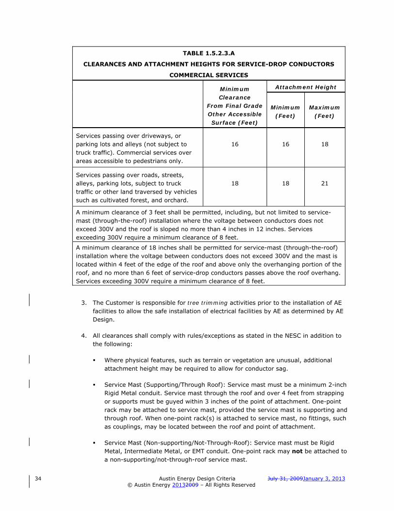
34 Austin Energy Design Criteria July 31, 2009January 3, 2013
© Austin Energy 20132009 – All Rights Reserved
TABLE 1.5.2.3.A
CLEARANCES AND ATTACHMENT HEIGHTS FOR SERVICE-DROP CONDUCTORS
COMMERCIAL SERVICES
Minimum Clearance
From Final Grade Other Accessible Surface (Feet)
Attachment Height
Minimum
(Feet)
Maximum
(Feet)
Services passing over driveways, or parking lots and alleys (not subject to truck traffic). Commercial services over areas accessible to pedestrians only.
16
16
18
Services passing over roads, streets, alleys, parking lots, subject to truck traffic or other land traversed by vehicles such as cultivated forest, and orchard.
18
18
21
A minimum clearance of 3 feet shall be permitted, including, but not limited to service-mast (through-the-roof) installation where the voltage between conductors does not exceed 300V and the roof is sloped no more than 4 inches in 12 inches. Services exceeding 300V require a minimum clearance of 8 feet.
A minimum clearance of 18 inches shall be permitted for service-mast (through-the-roof) installation where the voltage between conductors does not exceed 300V and the mast is located within 4 feet of the edge of the roof and above only the overhanging portion of the roof, and no more than 6 feet of service-drop conductors passes above the roof overhang. Services exceeding 300V require a minimum clearance of 8 feet.
3. The Customer is responsible for tree trimming activities prior to the installation of AE facilities to allow the safe installation of electrical facilities by AE as determined by AE Design.
4. All clearances shall comply with rules/exceptions as stated in the NESC in addition to the following:
Where physical features, such as terrain or vegetation are unusual, additional attachment height may be required to allow for conductor sag.
Service Mast (Supporting/Through Roof): Service mast must be a minimum 2-inch Rigid Metal conduit. Service mast through the roof and over 4 feet from strapping or supports must be guyed within 3 inches of the point of attachment. One-point rack may be attached to service mast, provided the service mast is supporting and through roof. When one-point rack(s) is attached to service mast, no fittings, such as couplings, may be located between the roof and point of attachment.
Service Mast (Non-supporting/Not-Through-Roof): Service mast must be Rigid Metal, Intermediate Metal, or EMT conduit. One-point rack may not be attached to a non-supporting/not-through-roof service mast.

July 31, 2009January 3, 2013 Austin Energy Design Criteria 35
© Austin Energy 2013 2009 – All Rights Reserved
A maximum of 10 feet of service-drop conductors may pass over the roof of the structure being served, regardless of required height above roof and/or slope of roof. EXCEPTION: A maximum of 10 feet of service-drop conductors may pass over roof of the building or structure to which the service-drop is not attached, regardless of required height above roof and/or slope of roof when the service drop meets all the following conditions:
o The building or structure is on the same piece of property and owned by the same Customer as the building being served to which the service-drop is attached (such as a garage or storage building)
o The voltage between the service-drop conductors does not exceed 300 volts
o The minimum vertical clearance is a minimum of 3.5 feet,
Service-drop conductors shall not pass within 3 feet, measured horizontally, or over or under any portion of a building or structure to provide service to another building or structure except as allowed in this Design Criteria. Additional clearances may be required as indicated in Section 23 of the NESC.
Service-drop conductors shall not pass within 3 feet, measured horizontally, or over or under signs, chimneys, billboards, radio and television antennas, tanks, and other installations not classified as buildings. Additional clearances may be required as indicated in Section 23 of the NESC.
For more information, contact AE Design.
HIGHLY RECOMMENDED: For safety reasons, the Customer should contact AE to have the electric power de-energized before working near AE facilities.
5. Anchorage of Overhead Service-Drop Conductors
a. The Customer shall provide (1) an adequate anchorage for the service-drop conductors, using a one-point rack(s) and (2) a suitable location for AE's metering equipment. AE shall furnish and the Customer shall install and maintain the one-point rack(s).
b. For services rated 800 amps or less, a single one-point rack shall be used for 3-wire and 4-wire. The rack shall be installed within 12 inches below the weatherhead at the required attachment height.
For services rated over 800 amps, three one-point racks shall be installed for 3-wire services and four one-point racks for 4-wire services. The racks shall be installed 10 to 12 inches apart, measured center to center.
Factory-assembled racks are allowed, as approved by AE Design. The Customer shall furnish, install, own, and maintain these racks.

36 Austin Energy Design Criteria July 31, 2009January 3, 2013
© Austin Energy 20132009 – All Rights Reserved
Multiple racks installed horizontally shall be installed a maximum of 12 inches below the weatherhead(s) at the required attachment height. The center point of the racks shall be directly below the weatherhead(s).
Multiple racks installed vertically shall be installed with the highest rack within 12 inches below the weatherhead and the lowest rack at the required attachment height.
c. The service-drop conductors shall be attached to a permanent building or structure at the point of attachment designated by AE - usually a location closest to AE’s nearest facilities/pole. The Service Spot & Conduit Section or AE Design shall determine the point of attachment on the Customer’s building or structure.
d. In order to provide adequate support for the service, the Customer shall use a minimum ½-inch diameter threaded bolt with nut and washers to securely attach the one-point rack(s) dead-end attachment securely to the structural frame of the building. On a wood frame structure, the Customer shall provide a securely attached minimum 2-inch x 4-inch header for this purpose.
Meter sockets and service entrance to the point of delivery are not considered complete until the one-point rack(s) has been properly installed.
e. Wherever the building height does not permit the required clearances for the service-drop conductors, the Customer shall provide approved permanent metal service supports (see 1.5.2.1.I).
B. Service Drop Lengths. For either permanent or temporary services, the Customer's service entrance facilities (such as service equipment, service conductors, or one-point rack) shall be installed relative to the service drop length according to the following (see section 1.10.6):
5-foot minimum
Regardless of service size: service drop length measured horizontally and perpendicular to AE's facilities (poles and overhead lines) (Also see Section 1.10.6.1.)
75-foot maximum
For service entrance equipment rated 225 amps or less: service drop length measured horizontally/radially, from AE's facilities (pole serving Customer's facilities)
55-foot maximum
For service entrance equipment rated over 225 amperes but 350 amperes or less: service drop length measured horizontally/radially from AE’s facilities (pole serving Customer’s facilities)
Contact AE Design
For service entrance equipment rated more than 350 amperes
All other maximum service lengths shall be specified by AE Design. Point of attachment must be able to withstand 400 pounds of tension.
C. Service Head (Weatherhead)

July 31, 2009January 3, 2013 Austin Energy Design Criteria 37
© Austin Energy 2013 2009 – All Rights Reserved
1. Customer’s Service Conductors. To permit connection with AE's service-drop conductors, the Customer’s service conductors must extend as follows according to the wire size:
#6 AWG through #1/0 AWG 18-inch minimum plus the distance from the service head to the rack
#2/0 AWG and larger 36-inch minimum plus the distance from the service head to the rack
If these conductor lengths are not provided, the CUSTOMER must rewire to meet the requirement.
2. The service head weatherhead head shall be approved weatherproof construction and installed to prevent the entrance of rain. The service head shall terminate within 12 inches above the one-point rack on the building, where the structure will permit.
3. For multiple service headweatherheads, CUSTOMER service conductors shall reach the rack(s) on the building (plus 36 inches). Each service headweatherhead shall have a full-current neutral. AE SHALL CONNECT THE CUSTOMER’S CONDUCTORS WITH AE’S SERVICE-DROP CONDUCTORS. No more than six service conductors per phase will be connected at the service point.
1.5.2.4 Customer-installed Underground Services and Civil Work for AE Infrastructure
A. Primary and Secondary Conduit, Pull-Boxes/Manholes, and Equipment Pads for AE Infrastructure
1. Underground primary and secondary infrastructure conduit, pull-boxes/manholes, and equipment pads installed on the source side (ahead) of the point of service for AE electrical facilities shall be installed with respect to final grade in utility easements or easements granted to AE. They shall not be installed under or permitted to pass under or through buildings or structures, including, but not limited to, such things as porches, stairways, decks, garages, or storage buildings.
2. All primary and secondary underground infrastructure conduit, in which AE installs AE conductors, shall be rigid metal or schedule 40 PVC. The conduit shall be limited to a maximum of two 90-degree bends, or equivalent, between accessible pulling points (for example, transformer and pull-box). No heated bends are permitted.
Primary conduit shall be installed a minimum of 30 inches deep and the secondary conduit shall be installed a minimum of 24 inches deep, measured to the top of the conduit from the current grade and not less than 30 and 24 inches respectively for final grade.
NOTE: All conduit installed crossing COA streets or installed in the COA public right of way shall be a minimum of 36 inches deep measured to the top of the concrete encasement/cap or the conduit if other backfill.

38 Austin Energy Design Criteria July 31, 2009January 3, 2013
© Austin Energy 20132009 – All Rights Reserved
Only communication cables are allowed in the same trench with AE facility conduits and shall be installed a minimum of 12 inches above and to the side of the top electrical conduit. (Primary and secondary risers shall be approved rigid metal.) For more information, contact AE Design.
3. When the civil work for AE facilities (or any service conduit ahead of the AE meter) has been installed, inspected, and approved by AE, the final grade shall not be changed by any excavation, filling, landscaping, or sodding without prior written approval of AE (see section 1.10.10).
4. AE Design will specify requirements for pull-boxes, manholes, equipment pads, and such.
5. Contact the AE Work Management Section (or AE Civil Inspection Section for Major Project or Network Installations) for an on-site preconstruction review with AE inspector(s) of the proposed Customer installed civil work installation.
B. Customer Installed, Owned, and Maintained Underground Service and Service Laterals
1. COA Electrical Inspection Section must inspect the Customer-installed and -owned service lateral conductors and the Customer-owned electrical service equipment. AE must inspect the service lateral conduit on the source side of the AE meter (see Section 1.5.2.4.B.2-7).
2. Service lateral conduit installed on the source side of the AE meter shall be installed a minimum of 24 inches deep with respect to final grade measured to the top of the conduit.
3. The Customer-installed service lateral conduit installed on the source side of the AE meter shall be run from the AE energy supply point to the closest point on the Customer’s building or structure or equidistant (as designated by AE Design or AE Spots & Conduit) to a rack or pedestal (pre-approved by AE Design) suitable for mounting the riser conduit and AE meter base. The service lateral conduit shall be no more than 150 feet long and it shall not have more than a total of 270 degrees of preformed bends. and have no more than two 90-degree bends.
4. All exposed conduit at the building/structure must be strapped to the structure and flush with the wall. Conduit must be capped at the riser pipe, especially if it is cut off at the slab, to prevent debris from falling into the 90.
All risers must be cut level with the slab if the masonry or siding is not completed when the conduit or 90 inspection is requested. (Conduit inspections will be based upon the load specified on the Electric Permit.)
5. Multiple service conductors that are furnished, installed, owned, and maintained by the Customer and that are serviced by AE from one service point location shall be grouped. Only one circuit is permitted per conduit.
6. Multiple meters shall be grouped and located on the exterior finished surface of the building or structure at a location approved by AE Design.

July 31, 2009January 3, 2013 Austin Energy Design Criteria 39
© Austin Energy 2013 2009 – All Rights Reserved
7. Service lateral conductors installed by the Customer ahead of the meter shall be installed as follows:
a. Underground conduit (24 inches minimum depth trench to top of conduit below final grade) from the last underground AE electric facility (such as service box, pull-box or AE transformer designated by AE Design or AE Spots & Conduit) to the bottom of the last 90-degree bend (24-inch minimum bend radius) ahead of the first above-grade enclosure (such as service distribution enclosure, junction box, wireway, self-contained meter, transocket, or CT enclosure) shall be one of the following:
Rigid Metal (Rigid Galvanized Steel).
Rigid Nonmetallic Schedule 40 or Schedule 40 PVC (Electrical PVC - Gray Color). No heated bends are permitted.
b. The last 90-degree bend (24-inch minimum bend radius) ahead of the first above-grade enclosure (such as service distribution enclosure, junction box, wireway, self-contained meter, transocket, or CT enclosure) shall be one of the following:
Rigid Nonmetallic Schedule 80 or Schedule 80 PVC (Electrical PVC - Gray Color) No heated bends are permitted.
Ridge Metal (Rigid Galvanized Steel).
The 90-degree bend(s) should be pointed toward the AE service box, pull-box, or transformer designated by AE Design or AE Spots & Conduit.
c. Exterior of building only. The top of the last 90-degree bend (24 inch minimum bend radius) ahead of the above-grade enclosure (such as service distribution enclosure, junction box, wireway, self-contained meter, transocket, or CT enclosure) to the enclosure shall be one of the following:
Rigid Nonmetallic Schedule 80 or Schedule 80 PVC (Electrical PVC - Gray Color) No heated bends are permitted.
Ridge Metal (Rigid Galvanized Steel).
The Customer shall stub the schedule 80 PVC or approved rigid metal conduit down from the service distribution enclosure to achieve a depth of 24 inches minimum (to top of conduit) below grade trench depth.
d. All service conduits shall be 2-, 3-, 4-, or 5-inch with no half sizes permitted.
e. Junction boxes and wireways as per Service Distribution Enclosures (Tap and J Boxes) and Wireway Specifications in section 1.14.0. Tap boxes, junction boxes, service distribution enclosures, wireways, and CT enclosures ahead of metering equipment shall have a minimum of two 3/16-inch diameter holes drilled (or factory-installed provisions) for AE to install utility seals. These holes shall be drilled on each side for junction boxes and each end for wireways.
8. Conductors, other than service conductors, shall not be installed in the same service raceway with service-entrance cables. (Also, metered and unmetered conductors shall not be installed in a common raceway.)

40 Austin Energy Design Criteria July 31, 2009January 3, 2013
© Austin Energy 20132009 – All Rights Reserved
EXCEPTION: Grounding and bonding conductors may be installed in the same raceway.
9. Neutral conductors of 3-phase and single-phase connected services shall have the full current-carrying capacity of the largest energized conductor from the Customer’s service point to the Customer's service disconnect(s) at the service equipment. The neutral conductor must be properly marked and grounded.
10. High-leg Phase Conductors. Particular attention shall be given to marking high-leg phase conductors feeding from a 3-phase, 4-wire, 120/240V delta secondary source. The high-leg shall be effectively identified in accordance with NEC 230-56 (marked by orange tape).
The high-leg shall always be connected as follows:
In meter sockets, including pre-wired transockets
to the right hand terminals
In CT enclosures To either the right hand CT (left to right), or the bottom CT (top to bottom)
In service equipment to the center bus
The neutral conductor must have the full current-carrying capacity of the largest energized conductor(s) (see Sect. 1.5.2.4.B.9).
11. Single-phase installations shall be 3-wire; three-phase installations shall be 4-wire. Conductor sizes shall conform to the NEC and approved by the COA Electrical Inspection Section. Minimum size service conductors for connection to AE facilities shall be #6 AWG copper or equivalent for commercial permanent services. Maximum size service conductors for connection to AE facilities shall be 750 kcmil.
12. Service conductors must be consistent in size, type (copper or aluminum), and such through the metering equipment. If the meter is not located at the point of service (where the Customer conductors are connected to AE facilities), there must be no splices, connections, or Customer-accessible enclosure between the point of service and the meter. Outlet, device, cutout, pull or junction boxes, cabinets, wireways, gutters, conduit bodies (such as, condulets–LB, LL, LR) or any other apparatus that is designed and intended to allow access to conductors shall not be allowed ahead of metering equipment.
EXCEPTION: Service distribution enclosures. Junction boxes and wireways as permitted for multiple-meter and multiple-disconnect installations in Service Distribution Enclosures (Tap or “J” Box) and Wireway Specifications in section 1.14.0.
EXCEPTION: (From section 1.3.9) For 277/480V three-phase self-contained meter sockets and for 480V three-phase or for any low voltage secondary voltage service above 300V up to 600V phase to phase or leg to leg, a service load break disconnect switch shall be installed in close proximity to and on the line side (ahead) of the metering equipment. [Line-Disconnect-Meter-Load]

July 31, 2009January 3, 2013 Austin Energy Design Criteria 41
© Austin Energy 2013 2009 – All Rights Reserved
13. All above-grade service conduit shall be exposed and continuous on the exterior-finished surface of the building or structure.
EXCEPTION: The portion of the service mast through the eaves (overhang portion) of the roof is not required to be exposed.
14. When the Customer desires AE to install the meter on the building or structure (rather than taking service at the transformer or service-box/pull-box), AE requires that the Customer installed, owned, and maintained service conduit and service lateral conductors installed ahead of the AE meter(s) not be installed under or through a building or structure, including, but not limited to, porches, stairways, decks, carports, garages.
Should future ordinances or legislation require the AE meter to be the point of service and where the above conditions are not met, the Customer assumes the total responsibility for establishing a master-meter/submeter system or for relocating the service conduit and service lateral conductors so that they are AE-accessible.
1.5.2.5 Underground Secondary Voltage Service From Secondary Riser - Commercial
A. General. In areas where the appropriate overhead primary distribution facilities are available, a secondary riser is the preferred method of providing 120/240V three-phase 4-wire underground service. Other secondary service voltages are also available by means of a secondary riser where the appropriate overhead distribution facilities are available. All underground services from secondary risers must meet electrical demand load conditions outlined in Table 1.5.2.2.
B. Customer and AE Commercial Service Installation Responsibilities
1. Customer Responsibilities (on the Customer’s property)
a. If the Customer-installed service lateral conductors are no larger than one 500 kcmil or two 4/0 AWG per phase, the Customer shall furnish, install, own, and maintain a 36-inch pull-box (load bearing or nonbearing as specified by AE Design) at base of pole. (In some cases, an 18-inch service box may be allowed for 200 amp and smaller service entrances where there is no need to allow for load growth and where the Customer-installed service lateral conductors are no larger than one 1/0 AWG per phase) or If the Customer-installed service lateral conductors are larger than one 500 kcmil or two 4/0 AWG per phase, the Customer shall furnish, install, own, and maintain a 48-inch pull-box (load bearing or nonbearing) at base of pole as specified by AE Design.
b. The Customer shall furnish, install, own, and maintain stub-up from service box/pull-box to pole and first 10-foot section of rigid, galvanized steel riser conduit up the pole. The riser's 90-degree bend with minimum 24-inch radius installed by Customer shall be rigid metal conduit and encased in concrete. The number and size of riser conduits will be determined by AE Design (see drawing General Riser Detail in Appendix C - Exhibits).
42 Austin Energy Design Criteria July 31, 2009January 3, 2013
© Austin Energy 20132009 – All Rights Reserved
c. The Customer shall dig and backfill trench from meter/service location to service box/pull-box. Trench shall be a minimum of 24 inches deep from grade to top of service conduit.
d. The Customer shall furnish, install, own, and maintain the service lateral conduit, approved rigid metal, or schedule 40 PVC, from the last 90 degree bend with 24 inch minimum bend radius ahead of the meter/service location to service box/pull-box (maximum length of 150 feet.) No heated bends are permitted.
The last 90-degree bend with 24-inch minimum bend radius ahead of the meter and the service riser conduit to the meter shall be approved rigid metal or schedule 80 PVC.
All service conduit shall be 2-, 3-, 4-, or 5-inch with no half sizes permitted.
HIGHLY RECOMMENDED: Contact the AE Work Management Section for an on-site preconstruction review with AE inspector of the proposed civil installation.
e. The Customer shall furnish, install, own, and maintain the service conductors from meter/service location into service box/pull-box. The service point shall be the service box/pull-box or as designated by AE Design. The Customer shall leave a 36-inch minimum conductor tail extending from (out of) the top of the service box or pull-box.
If a bonding conductor is required by the NEC, the Customer shall install the bonding conductor, and AE shall make the necessary connections. THE CUSTOMER SHALL NOT BREAK INTO SERVICE BOX/PULLBOX WITHOUT AE APPROVAL AFTER AE CONDUCTORS HAVE BEEN INSTALLED except as approved by AE Design or AE Spots and Conduit.
CAUTION: The Customer is not allowed under any circumstances to break into any AE pull-box containing AE primary voltage conductors.
f. The Customer shall request the following inspections:
AE Work Management Section - inspects the service lateral conduit ahead of the AE meter, the box/pull-box, the underground secondary conduit to the pole, the 90 degree bend at the pole, and 10-foot riser conduit extension of rigid galvanized steel up the pole. AE installs conductors from the pull-box up the pole and makes the connections in the pull-box.
Contact the AE Work Management Section (or AE Civil Inspection Section for Major Project or Network Installations) for an on-site preconstruction review with AE inspector(s) of the proposed Customer installed civil work installation.
COA Electric Inspection Section - inspects the Customer-installed service lateral conductors from the service box/pull-box to the meter/ service equipment location.

July 31, 2009January 3, 2013 Austin Energy Design Criteria 43
© Austin Energy 2013 2009 – All Rights Reserved
IMPORTANT: Do not backfill trench or encase 90-degree bend(s) or service conduit until the above inspections by AE have been completed and approved.
2. AE Responsibilities
a. Install upper portion of secondary riser conduit on pole to complete riser.
b. Install conductors in riser conduit from pole-mounted transformer(s) into service box/pull-box.
c. Connect AE conductors with Customer service conductors in service box/pull-box.
1.5.2.6 Padmounted Transformer Secondary Voltage Service - Commercial
A. General. Where underground secondary voltage service is provided by means of underground primary voltage cable, padmounted transformers, and associated equipment, the Customer will need to provide space on his property and the necessary easements for the required AE underground cable, underground facilities, and padmounted equipment. The Customer is required to install the civil work for AE facilities installed on the Customer’s property and to pay AE any additional cost differential between the overhead and underground distribution costs. AE Design will determine this cost. The Customer must also grant the City an easement on the City's standard form. The padmounted transformers and associated equipment must be installed on concrete pads or in transformer vaults. All Customer installed civil work for AE facilities must comply with all provisions of the COA Design Criteria, NESC, NEC, AE Design, and any applicable Specifications, Rules, Regulations, and Conditions. For more information, contact AE Design.
B. Metering Equipment. The metering equipment shall be grouped and located on the exterior finished surface of all buildings. If multiple meters are served from the padmount transformer, a service distribution enclosure must be installed on the exterior finished surface of the building or a structure adjacent to the building. The Customer-installed service lateral shall terminate in the service distribution enclosure. (See Section 1.9.0 and Appendix C - Exhibits.) For more information, contact AE Design.
C. Metering at Three-Phase Padmounted Transformers Only. When a dedicated three-phase padmount transformer serves one Customer and the CT-metering equipment is located in the secondary compartment of the transformer, the transformer secondary compartment shall be considered the point of service.
1. No other service and no other meter is intended to be served from this padmount transformer.
2. When CT-metering equipment is installed in the secondary compartment of the transformer, the S-1 socket enclosure shall be installed within sight of, visible and not more than 30 feet from, the transformer on the exterior finished surface of the building or structure or at transformer location on a rack on a separate pad or an extension of the transformer pad. (See Single Meter - CT Metering at Transformer in Appendix C - Exhibits.)

44 Austin Energy Design Criteria July 31, 2009January 3, 2013
© Austin Energy 20132009 – All Rights Reserved
The conduit from the secondary compartment to the S-1 socket shall be minimum size 1¼ inches, either rigid metal conduit or Schedule 80 PVC conduit, with a number 6 copper ground installed with at least 4 feet of wire pulled in the secondary compartment for grounding, and bonded to the S-1 socket’s grounding terminal, and with a pull-string installed.
D. Underground Installation Responsibilities. AE will provide a padmounted transformer service in accordance with the following outlined conditions. Refer to Table 1.5.2.2.
1. Customer’s Responsibility
a. The Customer shall furnish, install, own, and maintain the following with respect to final grade in accordance with AE plans and specifications as provided by AE Design (based on Customer-furnished AutoCAD site and facility drawings as required by AE Design):
Concrete pad for transformer(s)
Primary conduit system
Secondary conduit system: The number and size of conduits from secondary compartment of padmount transformer shall be determined by AE Design. Typically, AE single-phase padmount transformers can take a maximum of four conductors per leg/neutral. Three-phase padmount transformers up to 750 kVA can take a maximum of eight six conductors per phase/neutral. Three-phase padmount transformers from 1000 kVA up to 2500 kVA can take a maximum of ten conductors per phase/neutral. Only one circuit of Customer secondary service conductors can be installed per conduit.
Service boxes (18 inches) and pull-boxes (36 inches and 48 inches)
Primary riser: pull-box and stub-up from pull-box to pole and first 10-foot section of riser conduit (rigid galvanized steel) up pole. Riser’s 90 bend shall be rigid metal. Underground conduit shall be encased in concrete. Number and size of riser conduits shall be determined by AE Design (See General Riser Detail in section Appendix C - Exhibits.)
Service from the point of service up to and including the service entrance equipment.
b. The Customer shall extend secondary service conductors to the transformer secondary compartment with sufficient tails to reach the secondary terminals (plus 24 inches).
c. The CUSTOMER shall contact AE Design to determine the maximum number of conductors per phase that may be stubbed into the secondary compartment of a transformer and to facilitate the pulling of the Customer’s conductors into the secondary compartment.
d. The Customer shall provide an easement on the City’s standard form for the transformer pad, other padmount equipment, AE primary and secondary conductors, and associated AE facilities.
e. The Customer shall request the following inspections: (see 1.5.2.11)

July 31, 2009January 3, 2013 Austin Energy Design Criteria 45
© Austin Energy 2013 2009 – All Rights Reserved
AE Work Management Section - The primary cable conduit (30 inches below grade to the top of the conduit), the transformer pad(s), the transformer pad stub-outs of secondary or service lateral conduits, and the service lateral conduit ahead of the AE meter (24 inches below grade to top of conduit). (See Appendix C - Exhibits for trench details.)
Contact the AE Work Management Section (or AE Civil Inspection Section for Major Project or Network Installations) for an on-site preconstruction review with AE inspector(s) of the proposed Customer installed civil work installation.
COA Electric Inspection Section – Any service conduit installed behind the AE meter and all of the Customer's metering and service equipment. (See section 1.2.0 for phone numbers.)
IMPORTANT: Do not backfill trench or encase 90-degree bend(s) or any conduit head of the AE meter until the above inspections by AE have been completed and approved.
2. AE Responsibility
a. AE shall furnish, install, own, and maintain the following in accordance with the AE plans and specifications as provided by AE Design:
Transformer
Primary riser pole adjacent to Customer’s property line and complete riser up pole
Primary conductors from primary riser pole to transformer. There may be a charge for the installation of the primary conductors based on the cost differential between the underground installation cost and an estimated overhead installation cost to serve the same load.
b. AE shall make the cable terminations at the transformer. The service point shall be the secondary compartment of the transformer or as designated by AE Design.
1.5.2.7 Primary Voltage Service (Overhead and Underground) - Commercial
A. General. AE will provide electric service at a primary voltage of 12,470 Wye/7200V to service points upon a Customer’s request and subject to the following conditions:
1. AE Design will determine the primary voltage electric service capacity (kVA) available at the service location (see 1.5.2.2).
2. For overhead primary voltage service, see 1.5.2.7.B. For underground primary voltage service, see 1.5.2.7.C.
3. The Customer shall provide an AE-approved fault-interrupting device (fuses, breaker, or such other device that can also serve as a service disconnect) that will interrupt the maximum fault current available on the AE distribution system at the POS and will coordinate with other AE fault interrupting equipment as determined by

46 Austin Energy Design Criteria July 31, 2009January 3, 2013
© Austin Energy 20132009 – All Rights Reserved
AE Design. The Customer shall provide AE Design with two sets of interrupting device-operating curves and allow 30 days for evaluation prior to purchasing the interrupting equipment.
4. The Customer shall procure at Customer's own expense all facilities and equipment, including but not limited to primary metering equipment and enclosure (if underground), fault-current interrupting device, transformers, poles, conductors, manholes, and such required to take electric service at primary voltage as required in this Design Criteria and as specified by AE Design and the AE Electric Meter Operations Section.
5. Conversions. The Customer shall assume and pay all costs incurred by AE to convert the Customer to primary voltage service (plus any system changes if necessary).
6. AE may deny the primary voltage service option to a Customer if AE Design determines that providing primary service will have an adverse impact on AE’s electric system or on service to another Customer.
7. THE CUSTOMER ASSUMES ALL RESPONSIBILITY FOR FURNISHING, INSTALLING, OWNING, MAINTAINING AND OPERATING ALL FACILITIES ON THE CUSTOMER'S SIDE OF THE POINT OF SERVICE. All Customer-owned installations shall be in accordance with the NESC and NEC.
8. The service point shall be at the primary or metering enclosure. The enclosure shall be placed at a location nearest existing AE facilities as accepted and approved by AE Design.
9. In order to provide as continuous a service as possible, it is important for primary voltage Customers to consult with AE Design concerning the engineering, operating, and maintenance aspects of the Customer's facilities and possible problems and hazards associated with primary service. (AE normally does not provide secondary voltage service(s) to a property or Customer that is already primary metered but may provide separate secondary voltage service(s), if available, at total cost to the Customer.)
10. After consultation with the Customer and his/her engineer and before any construction has begun, the Customer's engineer shall supply a detailed set of plans of the proposed primary system to AE Design for review. Things such as available fault current, both present and future, operating voltage level and proper coordination of Customer's protective equipment with the facilities of AE should be determined before the Customer makes any equipment or facilities selection. In addition, comprehensive mechanical and one-line drawings (two sets) shall be supplied to AE Design for any switchgear that will interface with AE facilities.
THE CUSTOMER SHALL FURNISH, INSTALL, OWN, AND MAINTAIN ALL FACILITIES FOR DISTRIBUTING AND TRANSFORMING PRIMARY VOLTAGE TO ANY OTHER SERVICE VOLTAGE THAT MAY BE REQUIRED BY THE CUSTOMER.
B. Overhead Primary Voltage Service

July 31, 2009January 3, 2013 Austin Energy Design Criteria 47
© Austin Energy 2013 2009 – All Rights Reserved
1. AE will install the overhead primary metering equipment, the meter loop, and the meter on an AE pole and the Customer will pay the total cost for this installation.
2. The primary meter pole will be the point of service (unless otherwise designated by AE Design). AE will connect the Customer’s conductors to AE conductors at this pole.
3. The Customer shall furnish and install an AE-approved primary voltage fault interrupting device on the Customer’s first pole or other supporting structure on the load side of the point of service in accordance with the City's specifications and requirements. These installations shall be approved by AE Design to ensure compatibility with existing AE equipment.
4. AE shall maintain all facilities up to the service point.
5. The Customer shall be responsible for maintaining all facilities beyond the service point.
6. The COA Electric Inspection Section (and other regulating bodies) will inspect the installation of the Customer's primary service and equipment on the load side of the Customer’s service point including the primary metering enclosure.
C. Underground Primary Voltage Service
1. The Customer shall furnish and install conduit with respect to final grade in accordance with AE Design's specifications from the Customer's primary metering enclosure to the AE pole or a point on the Customer's property line designated by AE Design. Contact AE Design for details.
2. Where required, AE shall furnish and install conduit offsite from the Customer's property line to AE’s facilities at the Customer’s expense.
3. AE shall furnish and install primary cables from AE's facilities to Customer's primary metering enclosure.
4. The Customer shall furnish and install a primary metering enclosure. The enclosure shall contain:
The primary fault protection equipment (to separate the Customer’s facilities from the AE distribution system in the event of a fault on the Customer’s system)
The switching/disconnect equipment
The metering transformers (potential transformers and current transformers pre-wired to terminal boards for easy external access) as a part of the primary metering equipment enclosure at the service point in accordance with AE’s specifications and requirements (Contact AE Design).
AE Design and the AE CT Meter Operation Section shall inspect and approve this installation to ensure compatibility with existing AE equipment.
48 Austin Energy Design Criteria July 31, 2009January 3, 2013
© Austin Energy 20132009 – All Rights Reserved
5. The AE meter shall be mounted on a separate stand installed on an extension of the primary metering enclosure pad or on a separate pad adjacent to (must be visible from and not more than 30 feet from) the primary metering enclosure pad similar to Appendix C – Exhibits, Figures 1-11a and 1-11c for secondary metering installed in the secondary compartments of padmounted transformers.
6. AE shall maintain all facilities to the service point.
7. The COA Electric Inspection Section (and other regulating bodies) will inspect the final installation of the Customer's metering enclosure and all the primary service equipment on the load side of the Customer’s service point.
8. The Customer shall be responsible for maintaining all facilities beyond the service point except AE meters and AE metering equipment.
1.5.2.8 Service from Open Bushing Transformers in Fenced Enclosures - Commercial
A. New installations of AE open bushing transformers in fenced enclosures shall not be approved. Existing installations with this style of service shall be changed to padmounted transformer service if the Customer’s service is enlarged or modified (see 1.5.2.6).
B. Conversion to padmounted transformer service shall also conform to the following conditions:
1. The Customer shall furnish and install the concrete pad and conduit system in accordance with design provided by AE Design. This includes:
Pull-boxes and/or manholes, load bearing or nonbearing, at base of pole
Stub-up from the pull-box and/or manhole to pole
First 10-foot section of riser conduit (rigid metal) up pole.
2. AE shall furnish and install the primary conductor from AE’s riser pole to the transformer.
3. AE shall furnish and install the transformers.
4. The Customer shall furnish and install the service-entrance conductors to the secondary bushings of the AE transformer(s).
1.5.2.9 Secondary Voltage Service to Multiple-Meter/Shell Commercial Buildings
A. Service Disconnects and Meters. All multiple-meter/shell buildings shall have all service disconnects and meters grouped in a common location on the exterior finished surface of the building or structure after and adjacent to the service distribution enclosure. All meters and disconnects shall be permanently sequentially marked, in order for each respective occupancy or unit. Each unit or leased space shall be individually metered. Each meter shall have a service disconnect consisting of one fused switch or circuit breaker.

July 31, 2009January 3, 2013 Austin Energy Design Criteria 49
© Austin Energy 2013 2009 – All Rights Reserved
IMPORTANT: All new service terminal blocks ahead of the meter(s) shall be located in the service distribution enclosure. (New service additions to existing wireway services with No terminal blocks mayshall be located in the wireway except as approved by the COA Electric Inspection Section.) The wireway and junction box should be sized according to the table Junction Box and Wireway Specifications in Section 1.14.1.
IMPORTANT: Commercial transocket or CT services. – the conductors for a CT service may also use the common wireway if the CT service is located on the end of the wireway. Transocket or CT services served from a common wireway shall be limited to one service disconnect.
B. The electrical service for multiple-meter/shell building shall comply with the following requirements unless written approval is obtained from AE Design. (Customers should also contact the Development Review & Inspection Department, Electric Plan Review Section.)
1. A multiple-meter/shell building shall be given only one secondary voltage from AE’s facilities. All metered occupancies in that building shall be required to design their service to use that one voltage. If an occupant requires another voltage, then it shall be the Customer’s responsibility to furnish, install, own, and maintain the equipment necessary to transform AE’s voltage to the voltage required.
EXCEPTIONS: 1) A building or structure that has a service point with 120/240V or 120/208V service voltage (such as, strip shopping center) may be given an additional service point(s) for lease space(s) having an estimated demand of 600 kVA or greater (such as anchor store) as determined by AE Design. 2) Buildings greater than 400 feet in length may qualify for an additional point of service. Contact AE Design.
EXCEPTION: For 277/480V self-contained meter sockets, the service disconnect shall be installed on the line side (ahead) of the metering equipment. [LINE–DISCONNECT–METER–LOAD] (see 1.5.2.4.B.11 and 12).
HIGHLY RECOMMENDED: To allow ample space for future services, the Customer should stack the service disconnect and the meter socket.
HIGHLY RECOMMENDED: For shell buildings, the Customer should base the projected load size of the permanent service on a minimum of 15 volt-amps per square foot for multiple-fuel buildings or 20 volt-amps per square foot for all-electric buildings.
2. The Customer shall furnish, install, own, and maintain equipment on the load side (after) of the service point, including, but not limited to, service equipment, conduits, conductors, service distribution enclosures, junction boxes, wireways, ganged-meter socket assemblies, CT enclosures, transockets, meter pedestals, modular metering, and all related apparatus. Each Customer’s service installation shall be approved by the Development Review & Inspection Department, Electric Inspection Section, with maximum consideration to its impact on future installation of services. No installation shall be approved which will obviously hinder the addition of future services.
3. For underground installations, the Customer shall install conductors in the rear conduits of the secondary compartment of the AE padmount transformer first to allow
50 Austin Energy Design Criteria July 31, 2009January 3, 2013
© Austin Energy 20132009 – All Rights Reserved
easy access for future service. Conduits shall be installed from the secondary compartment of the padmount transformer to the service distribution enclosure so that the rear conduits in the transformer are also the rear conduits in the service distribution enclosure. Load side conductors are not permitted to exit the bottom section of the service distribution enclosure. This area shall be reserved for the line side conductors.
4. The Customer is responsible for all terminations in the service distribution enclosure.
5. The Customer’s initial electrical installation shall include the following:
a. Service distribution enclosure. Contact the Development Review & Inspection Department, Electric Inspection Section, for information and approval prior to purchasing and installation.
b. The required number and size of service conductors, as per calculated load for entire building per the NEC, must be pulled from service point and properly terminated in service distribution enclosure.
c. Proper service grounding and bonding as indicated in 1.5.2.1.O Grounding and Bonding of Electric Services.
d. Wireways, metering equipment, service disconnects, terminal blocks, lugs, and any other equipment to complete service installation as required.
i. For underground, adherence to AE Design requirements (such as transformer pads, primary and secondary conduit, primary and secondary risers, service boxes, and pull-boxes) is mandatory (see 1.5.2.4).
ii. For overhead, one or multiple one-point racks and weatherheads should be installed as required (see 1.5.2.3.A.5). Every weatherhead shall have a neutral conductor(s) and the neutral conductor(s) must have the full current-carrying capacity of the largest energized conductor(s).
6. House Meter. The Customer may install one self-contained meter socket for security lighting, fire safety, sprinkler system, and such. The service conductors for this service may be served from either the service distribution enclosure or service point (the Customer may request and install an optional 2-inch conduit in the padmounted transformer secondary compartment for the house meter service). The location of the meter socket and service disconnect shall be within sight of (or visible and not more than 50 feet from) the service distribution enclosure.
Overhead Service: Remember in planning for a house meter that no more than six service conductors per phase shall be connected at the service point.
Underground Service: The optional 2-inch house meter conduit is in addition to the maximum number of conduits permitted by the AE Design. If there is ample space, it shall be installed at the rear of the secondary compartment of the padmount transformer behind the required conduits.
July 31, 2009January 3, 2013 Austin Energy Design Criteria 51
© Austin Energy 2013 2009 – All Rights Reserved
HIGHLY RECOMMENDED: The house meter service should be installed so as to allow ample space for future services.
HIGHLY RECOMMENDED: For safety reasons, the Customer should contact AE to have the electric power de-energized before working inside a service distribution enclosure. The Customer is responsible for forewarning other tenants being served from this enclosure and/or transformer when de-energizing will occur.
1.5.2.10 Secondary Voltage Service to Combination Commercial/Residential Buildings
A. Combination commercial/residential buildings, such as multi-story condominiums or apartments with commercial/retail businesses on the first few floors and residential dwellings on the upper floors, may be served with separate secondary voltage services and treated as separate commercial and multi-metered residential Customers (at the Customer’s request) under the following conditions:
The commercial and residential portions are grouped such that they are distinctly separate load areas as determined by AE Design
Electrically separate systems are separated from each other by a 2-hour fire wall minimum
Both services are not accessible from the same space as determined by the COA Electric Inspection Section and any other authorized inspection entity.
B. The residential and commercial services will both be subject to the respective conditions and requirements of this Design Criteria. All AE metering must be installed at the first floor or ground level (except as allowed in writing by AE Design). If metering is allowed above the first floor/ground level, it must be accessible by AE personnel from the ground level 24/7. The main disconnects for each metering room must be located at the ground floor level. (See Section 1.3.9) For more information, contact AE Design.
C. Combination commercial/residential buildings that are not grouped into distinctly separate commercial and residential areas (as determined by AE Design) will be treated as all commercial per the requirements of this Design Criteria manual.
D. All three-phase service requests and all single-phase requests where the services to both the commercial and residential sections of a combination building (or to separate residential and commercial buildings) must be provided from the same AE transformer will be treated as all commercial as far as Customer requirements are concerned and are subject to the commercial requirements of this Design Criteria and AE Design.
1.5.2.11 Electric Service Inspections – Commercial
A. AE Work Management shall inspect all commercial (non network) underground civil work installed by the Customer for AE facilities and all service lateral conduit ahead of the AE meter except as designated by AE Design. The inspection of any underground civil work must be completed before the Customer backfills the excavation.
HIGHLY RECOMMENDED: Contact the AE Work Management Section for an on-site preconstruction review with civil work inspector of the proposed civil installation.

52 Austin Energy Design Criteria July 31, 2009January 3, 2013
© Austin Energy 20132009 – All Rights Reserved
B. COA Electrical Inspection Section must inspect all underground Customer installed, owned, and maintained service lateral conductors (see Section 1.2.0). Again, AE Work Management shall inspect all service lateral conduits installed ahead of the AE meter.
C. AE Electric Meter Operations, AE Spots & Conduit, or AE Design (depending on the nature and stage of the project) shall inspect all Customer electric service installations (new or changes to existing) on the exterior finished surface of a building or structure served by AE up to and including the point of service. Inspections are completed both during construction and upon completion to ensure compliance with the NESC and the AE Design Criteria.
D. AE cannot install or energize the permanent electric service until the electric service inspection has been made and approved as required in this Design Criteria, and AE has received notice of inspection/approval from the City of Austin’s Permit & License Center – Electrical Inspection Section (and any other authorized inspection entity).
E. Only AE shall make the connections (and disconnections) of the Customer's wiring to AE's facilities. In addition, only AE personnel shall remove AE meters or, break City seals, and such, except in cases specifically authorized by AE, or its designee (call AE CT Metering and Inspection Section). The following will be inspected by AE, or its designee, prior to or at the time of the connection of metering equipment as indicated:
1. Meter Socket(s) – COA Electric Inspection Section (EIS)
2. Service Distribution Enclosure – AE CT Metering and Inspection Section & EIS.
3. CT Meter Services – AE CT Metering and Inspection Section & EIS.
4. Old service check (no meter at location) – Start with COA Development Review.
5. Turn on meter (meter existing) – AE at time service is turned on.
6. Read and change meter – AE at time of read and change.
1.5.2.12 Safety and Clearances - Commercial
A. The Customer shall, at all times during construction and maintenance (including temporary or permanent facilities), use proper procedures complying with all building codes, State laws, and Occupational Safety and Health Administration (OSHA) requirements.
B. Minimum Working Clearances from Energized Overhead High Voltage Electric Utility Lines and Minimum Clearances from AE Underground Electric Utility Lines and AE Padmounted Equipment – See Section 1.10.0.
C. Relocation of AE Facilities. Where feasible, AE will temporarily (or permanently) relocate AE facilities at the Customer’s expense. Such relocations often require considerable planning and effort, thus the Customer should address these issues with AE Design at the beginning of the project for both construction power and permanent service.
D. Customer's facilities/installations shall not be installed under or over AE distribution facilities and shall maintain a minimum horizontal clearance of 5 feet from AE distribution facilities. Additional horizontal and vertical clearances may be required as

July 31, 2009January 3, 2013 Austin Energy Design Criteria 53
© Austin Energy 2013 2009 – All Rights Reserved
indicated in Section 23 of the NESC. This includes, but is not limited to, Customer’s buildings, parking garages, light poles, signs, billboards, chimneys, radio and television antennas, tanks, and other installations. For more information, contact AE Design.
HIGHLY RECOMMENDED: For safety reasons, the Customer should contact AE to have the electric power de-energized before working near AE facilities. The Customer is responsible for all costs associated with the de-energizing and re-energizing service.
1.5.3 RESIDENTIAL Service in Non Network Areas
(See sections 1.3.0 and 1.4.0.)
1.5.3.1 General Conditions and Requirements – Residential
A. Prior to Electrical Service Installation. Before starting work on any new or upgraded electric service, the Customer shall ensure the land is a legal lot or tract as required under the Land Development Code.
B. Contact AE Design or AE Spots & Conduit. (See Sections 1.4.8 and 1.4.9) In order to facilitate electric service availability when needed, the Customer should discuss all electrical service issues with AE Design or AE Spots & Conduit well in advance of the desired service date to determine the requirements and time frame for providing electric service. Necessary information that should be included in the ESPA includes exact location of the property to be served, such as street address, lot and block number of subdivision, service voltage, equipment characteristics, connected load, and the size of the service entrance equipment including equipment ratings.
C. Charges. The Customer may be required to pay AE a line extension charge and/or an excess facilities/excess costs charge (see Section 1.3.0). AE Design will determine if either or both of these charges is applicable.
D. Service Location/Property Address. Property address must be located so that it will be visible from public right of way before the installation of the temporary meter loop and this address must clearly marked on the meter loop, meter pole, and/or meter pole braces (see Section 1.7.0). Property address shall be visible during design and construction phase and after completion of project.
E. Accessibility. AE infrastructure facilities shall only be placed in locations that are permanently truck accessible (such as along public street ROW, in alleys, or along private streets and drives – minimum 20 feet wide and 35 feet vertical clearance required) (see 1.4.11).
F. Grounding and Bonding of Electric Services. Electric services, including, but not limited to, service equipment, raceways, service distribution enclosures, junction boxes, wireways, enclosures, and any service conductor to be grounded/bonded shall be grounded/bonded in accordance with the NEC.
EXCEPTION: The grounding/bonding conductors for all services shall be copper only, with a minimum size of #6 AWG.
G. Meter Loop Location. Residential meter loops shall not be installed on manufactured or modular housing, mobile homes, portable buildings, or similar structures that are not

54 Austin Energy Design Criteria July 31, 2009January 3, 2013
© Austin Energy 20132009 – All Rights Reserved
legally a part of the property. (Exceptions are approved service poles, structures, pedestals, and such.)
The Service Spot & Conduit Section and/or AE Design shall designate and approve meter and service equipment locations (see Sections 1.5.3.6 & 1.5.3.7 for multiple metered buildings). The meter location(s) should normally be on the first floor or ground level. AE Design must approve meter location exceptions in writing.
H. Electric Permit Requirements for Meter Loop Placement/Meter Loop Replacement. An electric permit will be required for any new meter loop or for any meter loop replacement. Any replacement meter loop must be installed according to current codes whenever there is a need to replace a meter loop or a meter loop pole (such as replace a rotten service pole). COMMENT: When residential services are being rebuilt (for upgrade or repair), the Customer should contact COA Electrical Inspection for approval of service entrance equipment and method of installation.
I. Three-phase is not a standard AE residential service voltage. For Customer’s requesting three-phase secondary voltage service for residential dwellings, AE Design must approve such requests and determine if there will be an excess facilities cost. The Customer must take service under the conditions and requirements of commercial service (see Section 1.5.2.11) The service point for three-phase service shall be the secondary compartment of the transformer or as designated by AE Design.
1.5.3.2 Available Residential Electric Service
Electric residential service available in the AE service area (excluding network) is as follows in Table 1.5.3.2.
Table 1.5.3.2
VOLTAGE
[2] [3] [5]
RESIDENTIAL [4]
Overhead Secondary Riser Underground
min max min Max min Max
120/240V, 1PH, 3-Wire
[1]
800 [1]
800
[1]
800
[1] Contact AE Design concerning the AE Line Extension Policy
[2] Standard residential service voltage is 120/240V single-phase. Contact AE Design if you have any questions or other residential service requirements.
[3] If the available service does not meet the Customer's requirements as requested in the ESPA, AE may agree to supply the type of electric service Customer requires at an additional cost to the Customer if 1) the request is feasible and if 2) the Customer’s equipment and/or the manner of use does not jeopardize the quality of service to other AE Customers as determined by AE Design.
[4] 750 kcmil is the maximum wire size allowed.
[5] For the purpose of sizing AE facilities, AE Design shall determine the maximum expected Customer demand load amps that will be seen by AE facilities from the Customer’s total connected undiversified load information and building size as documented on the ESPA form.

July 31, 2009January 3, 2013 Austin Energy Design Criteria 55
© Austin Energy 2013 2009 – All Rights Reserved
AE facilities will be sized by AE Design accordingly. The maximum demand load amp services available from AE are defined in Table 1.5.2.2.
1.5.3.3 Overhead Residential Installations
A. Standard AE residential electric service is single-phase overhead on wood poles. AE normally installs, owns, and maintains the overhead facilities (primary, secondary, and service drops) from AE facilities to the Customer’s facilities.
B. A permanent overhead service drop not installed on the building or structure shall meet the following requirements:
Be installed on a treated 64-inch-minimum diameter pole/post or on a rack
Consist of treated wood or non-corrosive metal
Be supported by treated 4-inch minimum diameter poles/posts or galvanized rigid steel 2-inch minimum diameter poles/posts
The poles/posts shall be installed a minimum of 3 feet deep encased in concrete. Rack shall be installed permanently with sufficient bracing and shall be stationary.
For Customer services requiring meter bases rated over 350 amperes, the pole or rack will need to be engineered and a drawing provided confirming that the structure will support the AE overhead service tension. AE Design will provide the pole/structure loading requirements for the overhead service.
C. Service-Drop Conductors - Residential
1. General. Overhead service-drop conductors that are furnished and installed by AE connect AE's supply lines to the Customer-provided service conductors. The service point is the point at which AE's and the Customer's conductors are connected at the weatherhead(s) and one-point rack(s) location or as designated by AE Design. All connections of AE conductors at the service point shall be made by AE. For multiple weatherhead installations, every weatherhead shall have a neutral conductor and the neutral conductor must have the full current-carrying capacity of the largest energized conductor.
2. Clearances/Attachment Heights. NESC (Section 23) along with AE Design requirements require minimum clearances for service-drop conductors from final grade or other accessible surfaces, which shall be maintained at all times. To facilitate these clearances, minimum attachment heights shall be as listed in Table 1.5.3.3.C.2. For more information, contact AE Design.

56 Austin Energy Design Criteria July 31, 2009January 3, 2013
© Austin Energy 20132009 – All Rights Reserved
TABLE 1.5.3.3.C.2
CLEARANCES AND ATTACHMENT HEIGHTS FOR SERVICE-DROP CONDUCTORS RESIDENTIAL SERVICES
Minimum Clearance From Final Grade/ Other Accessible Surface (Feet)
Attachment Height1,2
Minimum
(Feet)
Maximum
(Feet)
Residential services over areas accessible to pedestrians only.
12 12.5 15
Services passing over driveways, or parking lots and alleys (not subject to truck traffic).
16 16 18
Services passing over roads, streets, alleys, parking lots, subject to truck traffic or other land such as cultivated, grazing, forest, orchards, etc. traversed by vehicles.
18 18 21
A minimum clearance above the roof of 3 feet shall be permitted for service mast installations, including, but not limited to service-mast (through-the-roof) installations where the voltage between conductors does not exceed 300V.
Where the voltage between conductors does not exceed 300V and the mast is located within 4 feet of the edge of the roof and above only the overhanging portion of the roof, a minimum clearance of 18 inches shall be permitted for service-mast (through-the-roof) installation. No more than 10 6 feet of service-drop conductors may pass above the roof overhang.
No more than 10 feet of service-drop conductors may pass above the roof.
1. The Service Spot & Conduit Section (for single-phase services) or AE Design (for three-phase services) may approve an attachment height, other than those listed in this table, based on the circumstances at the site location. However, minimum attachment height shall be maintained at all times to meet NESC requirements.
2. Attachment heights should in no case exceed the maximum as listed unless approved in advance by
AE Service Spot & Conduit Section (for single-phase services) or AE Design (for three-phase
services).
3. All clearances shall comply with rules and exceptions as stated in the NESC in addition to the following:
Where physical features, such as terrain or vegetation are unusual, additional attachment height may be required to allow for conductor sag.

July 31, 2009January 3, 2013 Austin Energy Design Criteria 57
© Austin Energy 2013 2009 – All Rights Reserved
Service Mast (Supporting/Through Roof): Service mast must be a minimum 2-inch Rigid Metal conduit. Service mast through the roof and over 4 feet from strapping or supports must be guyed within 3 inches of the point of attachment. One-point rack may be attached to service mast, provided the service mast is supporting and through roof. When a one-point rack (clamp-on type) is attached to service mast, no fittings, such as couplings, may be located between the roof and point of attachment.
Service Mast (Non-supporting/Not-Through-Roof): Service mast must be Rigid Metal, Intermediate Metal, or EMT conduit. One-point rack may not be attached to a non-supporting/not-through-roof service mast.
A maximum of 10 feet of service-drop conductors may pass over roof of structure being served, regardless of required height above roof and/or slope of roof. (Location must be accessible to AE personnel.)
Service-drop conductors shall not pass within 3 feet, measured horizontally, or over or under any portion of a building or structure to provide service to another building or structure. Additional clearances may be required as indicated in Section 23 of the NESC. EXCEPTION: A maximum of 10 feet of service-drop conductors may pass over roof of the building or structure to which the service-drop is not attached, regardless of required height above roof and/or slope of roof when the service drop meets all the following conditions:
o The building or structure is on the same piece of property and owned by the same Customer as the building being served to which the service-drop is attached (such as a garage or storage building)
o The voltage between the service-drop conductors does not exceed 300 volts
o The minimum vertical clearance is a minimum of 3.5 feet,
Service-drop conductors shall not pass within 3 feet, measured horizontally, or over or under signs, chimneys, billboards, radio and television antennas, tanks, and other installations not classified as buildings. Additional clearances may be required as indicated in Section 23 of the NESC.
For more information, contact AE Design.
HIGHLY RECOMMENDED: For safety reasons, the Customer should contact AE to de-energize the electric power before working near AE facilities.
4. Anchorage of Overhead Service-Drop Conductors
a. The Customer shall provide (1) an adequate anchorage for the service-drop conductors using a one-point rack for residential services or multiple one-point racks for large residential services and (2) a suitable location for AE's metering equipment. AE shall furnish and the Customer shall furnish instalinstall, own and maintain the one-point rack(s).

58 Austin Energy Design Criteria July 31, 2009January 3, 2013
© Austin Energy 20132009 – All Rights Reserved
b. For services rated 800 amps or less, a single one-point rack shall be used for 3-wire and 4-wire. The rack shall be installed within 12 inches below the weatherhead at the required attachment height.
For services rated over 800 amps, three one-point racks shall be installed for 3-wire services and four one-point racks for 4-wire services. The racks shall be installed 10 to 12 inches apart, measured center to center.
Factory-assembled racks are allowed, as approved by AE Design. The Customer shall furnish, install, own, and maintain these racks.
Multiple racks installed horizontally shall be installed a maximum of 12 inches below the weatherhead(s) at the required attachment height. The center point of the racks shall be directly below the weatherhead(s).
Multiple racks installed vertically shall be installed with the highest rack within 12 inches below the weatherhead and the lowest rack at the required attachment height.
c. The service-drop conductors shall be attached to a permanent building or structure nearest AE's last designated facilities (pole). The Service Spot & Conduit Section or AE Design shall determine the point of attachment on the Customer’s building or structure.
At AE’s option and discretion, attachment may be made at some other point, either because of the location and type of AE’s distribution system or in order to conform with construction of the building. This point of attachment shall be agreed upon by the Customer and the Service Spot & Conduit Section (see Section 1.4.8) or AE Design (see Section 1.4.9) before the installation of the service conductors, service equipment, one-point rack(s), metering equipment, or any other wiring on the premises.
AE shall furnish and the CustomerCustomer shall furnish, install, own and maintain the one-point rack(s) at this point of attachment.
d. In order to provide adequate support for the service, the Customer shall make provisions for the dead-end attachment (one-point rack) to be securely attached to the structural frame of the building using a minimum ½-inch diameter threaded bolt with nut and washers. On a wood frame structure, the Customer shall provide a securely attached minimum size 2-inch x 4-inch header for this purpose. Meter sockets and service entrance to the point of delivery are not considered complete until the one-point rack(s) has been properly installed.
e. Wherever the building height does not permit the required clearances for the service-drop conductors, the Customer shall provide approved permanent metal service supports (see 1.5.3.3.B).
D. Service Drop Lengths. The Customer's permanent/temporary service entrance facilities shall be installed according to the following requirements relative to the service drop length (see also Section 1.10.6.1):

July 31, 2009January 3, 2013 Austin Energy Design Criteria 59
© Austin Energy 2013 2009 – All Rights Reserved
5-foot minimum
Regardless of service size: Service drop attachment must be located out from under AE facilities measured horizontally from and perpendicular to AE's facilities (poles and overhead lines) (Also see Section 1.10.6.1.) AE will determine total permissible service drop length.
75-foot maximum
For service entrance equipment rated 225 amps or less: Service drop length measured horizontally/radially, from AE's facilities (pole serving Customer's facilities)
55-foot maximum
For service entrance equipment rated over 225 amperes but 350 amperes or less: Service drop length measured horizontally/radially from AE’s facilities (pole service Customer’s facilities)
Contact AE Design
For service entrance equipment rated more than 350 amperes.
All other maximum service lengths for larger loads or other smaller load conditions that allow longer service drop lengths than shown above shall be specified by AE Design. Point of attachment must be able to withstand 400 pounds of conductor tension.
E. Service Head (Weatherhead)
1. Customer’s Service Conductors. To permit connection with AE's service-drop conductors, the Customer’s service conductors must extend as follows according to the wire size:
#6 AWG through #1/0 AWG 18-inch minimum plus the distance from the service head to the rack
#2/0 AWG and larger 36-inch minimum plus the distance from the service head to the rack
If these conductor lengths are not provided, the CUSTOMER must rewire to meet the requirement.
All Customer service conductors shall have correct phase identification markings 12 inches from the servicehead.
2. The weatherhead head shall be approved weatherproof construction and installed to prevent the entrance of rain. The service head shall terminate above and within 12 inches of the one-point rack on the building, where the structure will permit.
3. For multiple weatherheads, CUSTOMER service conductors shall reach the rack(s) on the building (plus 36 inches). AE SHALL CONNECT THE CUSTOMER’S CONDUCTORS WITH AE’S SERVICE-DROP CONDUCTORS. No more than six service conductors per phase will be connected at the service point.
4. For multiple weatherhead installations, every weatherhead shall have a neutral conductor. The neutral conductor must have the full current-carrying capacity of the largest energized conductor.

60 Austin Energy Design Criteria July 31, 2009January 3, 2013
© Austin Energy 20132009 – All Rights Reserved
F. Tree Trimming. The Customer is responsible for all tree-trimming activities on the Customer’s property required by AE to allow for the safe installation of new (or for Customer requested modifications to) electrical facilities by AE. The Customer shall not trim trees adjacent to AE energized facilities. If such trimming is required or deemed necessary, contact AE Design or AE Spots and Conduit.
G. Clearances. See Sections 1.5.3.3.C.2 and 1.10.0.
1.5.3.4 Underground Residential Electric Service Installations
A. Underground Service Conditions and Requirements
1. AE normally requires the Customer to install with respect to final grade all the civil work (see item 5 below) for underground AE facilities located on the Customer’s property as designated by AE Design (see Section 1.4.9).
2. Underground Service Lateral from Existing AE Underground Facilities. See Service Only in Section 1.4.9.
3. Underground Agreement for Electric Service (Letter of Agreement). The conditions (and costs) under which underground electric service (or infrastructure) is supplied to a Customer shall be covered by an Agreement for Electric Service letter provided by AE Design.
IMPORTANT: This agreement by AE to the serve a particular installation underground applies only to the specified wiring and equipment (or the particular AE electrical distribution infrastructure needed) at the Customer-specified location given on the ESPA. The Customer shall notify AE Design as soon as possible concerning any contemplated change so that proper provisions may be made for adequate service, connection, and metering facilities.
4. AE-installed underground residential service lateral conductors shall be installed a maximum of 150 feet from the Customer's service equipment to AE’s nearest designated service box, pull-box, or transformer. AE Spots and Conduit shall determine the cost to the Customer for services over 150 feet but not over 200 feet for additional facilities, materials, and/or labor. All services exceeding 200 feet shall be referred to AE Design for voltage drop and flicker calculations and determining the cost to the Customer.
5. Customer-installed Civil Work
a. Customer-installed underground primary, secondary, and service conduit on the Customer’s property for AE facilities and all conduit installed on the line side (ahead) of the AE metering equipment shall be installed with respect to final grade and shall not be installed under or through a building or structure (including, but not limited to, porches, stairways, decks, carports, garages, and storage buildings).
b. All primary, secondary, and service conduit in which AE installs the conductors and all service conduit ahead of the AE meter shall be limited to a maximum of two 90-degree bends, or equivalent, between accessible pulling points (such as

July 31, 2009January 3, 2013 Austin Energy Design Criteria 61
© Austin Energy 2013 2009 – All Rights Reserved
transformer, service box, pull-box, or meter socket). AE Design shall determine installation requirements of primary and secondary risers and underground conduit.
c. Service conduit, from the service point or the last AE facility to the last 90-degree bend ahead of the metering equipment shall be rigid metal or schedule 40 PVC. The last 90-degree bend with 24-inch minimum bend radius and the service riser shall be rigid metal or schedule 80 PVC. No heated bends are permitted. There shall be no additional bends between the service riser and the AE metering equipment.
d. Secondary/service conduit runs of more than 75 feet shall also include an AE approved pull-string.
CAUTION: The Customer is not allowed under any circumstances to enter any AE equipment, manhole, pull-box, or other such facilities containing AE primary voltage cable. (Contact AE Design or AE Spots and Conduit)
e. Primary cable conduit shall be installed a minimum of 30 inches deep and secondary and service conduit shall be installed a minimum of 24 inches deep measured to the top of the conduit with for the current grade and not less than 30 and 24 inches respectively for final grade
Only communication cables are allowed in the same trench with electric conduits and shall be installed a minimum of 12 inches from the top electrical conduit (See Section 1.10.5.A). For more information, contact AE Design.
f. The Customer-installed civil work (conduit, pads, and such) required for permanent underground service (or infrastructure) shall meet the requirements as specified in this Design Criteria and as required by AE Design by drawing and/or in the Agreement for Electric Service. The service installation shall be completed from the last or closest AE facility and/or service point, as determined by AE, up to and including the service equipment. Civil work installation shall meet the requirements of AE Design and this Design Criteria. For more information, contact AE Design.
g. After the civil work for AE facilities has been installed, inspected, and approved by AE, the final grade shall not be changed by any excavation, filling, landscaping, or sodding without prior written approval of Austin Energy (see Section 1.10.10).
h. AE Responsibility for Customer-installed Facilities. AE ASSUMES NO RESPONSIBILITY FOR ANY PORTION OF THE CUSTOMER'S INSTALLATION. AE reserves the right to discontinue or refuse service to any apparatus or device which is not properly constructed, controlled, and protected, or for which the Customer has not provided the necessary easements or obtained the required inspections and permits, or for which (in AE’s opinion) may adversely affect the services to any Customer or that may be an improper or unsafe type.

62 Austin Energy Design Criteria July 31, 2009January 3, 2013
© Austin Energy 20132009 – All Rights Reserved
B. Underground Residential Service from a Secondary Riser
1. General. In areas where overhead primary distribution facilities are available, the secondary riser is the preferred method of providing underground 120/240V single-phase service for 800 amperes or less of maximum demand ampacity as determined by AE Design and that meet conditions outlined in Table 1.5.3.2. Underground padmount transformer services in overhead areas for such loads will be provided at the discretion of AE Design or if the Customer pays for the additional cost of such a service.
2. Customer Installation Responsibilities
a. The Customer shall furnish, install, own, and maintain a service box (load bearing or nonbearing) at base of pole as specified by AE Design.
b. The Customer shall furnish and install the stub-up from service box/pull-box to pole and first 10-foot section of riser conduit (rigid metal) up pole. Riser's 90-degree bend with minimum 24-inch bend set by Customer shall be rigid metal conduit and encased in concrete. The number and size of riser conduits will be determined by AE Design (see drawing General Riser Detail in Appendix C - Exhibits).
c. The Customer shall dig and backfill trench from meter/service location to service box/pull-box. Trench (on the Customer’s property) shall be a minimum of 24 inches deep from grade to top of service conduit.
d. The Customer shall furnish, install, and maintain the service conduit (approved rigid metal or schedule 40 PVC) from the last 90-degree bend ahead of the meter/service location to service box/pull-box. The last 90-degree bend with 24-inch minimum bend radius and the service riser shall be approved rigid metal or schedule 80 PVC. Service conduit shall be 2, 3, 4, or 5 inch with no half sizes permitted.
e. The Customer shall furnish, install, own, and maintain the service conductors from meter/service location into service box/pull-box. The service point shall be the service box/pull-box or as designated by AE Design. The Customer shall leave a 36-inch minimum conductor tail extending from the top of the service box or pull-box. If a bonding conductor is required by the NEC, the Customer shall install the bonding conductor, and AE shall make the necessary connections.

July 31, 2009January 3, 2013 Austin Energy Design Criteria 63
© Austin Energy 2013 2009 – All Rights Reserved
f. The Customer shall request the following inspections:
AE Work Management Section - inspects the service lateral conduit from the service box/pull box to the meter, meter pedestal, or service equipment location, the service-box/pull-box, and the conduit from the service-box/pull-box to the secondary riser, including the 90-degree bend and the 10-foot riser conduit up pole. AE installs conductors from the serve-box/pull-box up the pole.
Contact the AE Work Management Section (or AE Civil Inspection Section for Major Project or Network Installations) for an on-site preconstruction review with AE inspector(s) of the proposed Customer-installed civil work installation.
COA Electric Inspection Section - inspects the Customer’s service conductors from the service box/pull-box to the meter and service equipment location. Customer installs conductors from the service-box/pull-box to the meter.
Do not backfill trench or encase 90-degree bend(s) or conduit in concrete until the above inspections have been completed and approved.
3. AE Installation Responsibility
a. Install riser conduit on pole to complete riser.
b. Install conductors in riser conduit from pole-mounted transformer(s) into service-box/ pull-box.
c. Connect AE conductors with Customer service conductors in service-box/ pull-box.
C. Underground Service from Padmounted Transformers to Residential Lots and Subdivisions
1. General. Where the underground AE electric infrastructure is made available to individual residential lots by means of a system of underground primary voltage cable, secondary voltage cable, padmounted transformers, and associated equipment, the Customer (Developer/Builder) must provide space on his or her property for the required AE facilities and equipment.
The Customer must install the civil work for AE facilities installed on the Customer’s property and pay AE any additional cost differential between the overhead and underground distribution costs. AE Design will determine this cost.
The Customer must also grant the City an easement on the City's standard form for such installations and any associated underground cable. The padmount transformers and their accessory equipment must be installed on concrete pads.
All Customer-installed civil work for AE facilities must comply with all provisions of the City of Austin Design Criteria, NESC, NEC, AE Design requirements, and any applicable AE specifications, rules, standards, regulations, and conditions. For more information, contact AE Design.

64 Austin Energy Design Criteria July 31, 2009January 3, 2013
© Austin Energy 20132009 – All Rights Reserved
2. AE will provide single-phase, 120/240V service to residential units with a total combined ampere rating of service disconnects that shall not exceed 350 amps for a single, self-contained meter or 800 amps for a service consisting of two to four meters or CT service. For larger single-phase services, Customer should contact AE Design for availability. (See Table 1.5.3.2 for available service.)
3. In subdivisions completed (utilities installed and available at property line for construction of dwelling units) prior to July 31, 1997, the Customer (generally) must meet the requirements of the July 1, 1997 Developer/Builder Policy for Subdivisions (see 1.5.3.4.C.5 or 6).
4. In subdivisions completed (utilities installed and available at property line for construction of dwelling units) after July 31, 1997, the Customer (generally) must meet the requirements of the July 1, 1997 Developer/Builder Policy for Subdivisions (see 1.5.3.4.C.5 or.6).
5. Developer/Builder Policy for Subdivisions. As of July 31, 1997 , unless otherwise agreed by AE in its sole discretion, underground service in new residential areas is available according to the following policy:
a. Developer/Builder is responsible for all civil work required to extend electrical facilities according to AE’s design and construction requirements as required in the Agreement for Electric Service, this Design Criteria, the NEC, NESC, and all applicable codes, rules, regulations, standards, specifications, and such.
b. Developer/Builder must acquire and provide all of the required materials including, but not limited to conduit, bell ends, service boxes/ pull-boxes, manholes, manhole covers, or junction boxes. Materials used must meet AE's detailed specifications. No heated bends are permitted.
c. Developer/Builder is responsible for conducting all trenching and backfilling activities, including, but not limited to, those required to install the primary and secondary duct systems, installation of service boxes/pull-boxes, conduit, bell ends and for building the concrete transformer pads and meter pedestal foundations according to the AE Design Criteria and AE Design requirements.
d. AE reserves the right to inspect the quality of materials as well as the construction phase of a project during installation of any materials and equipment by the Developer/Builder.
e. The Developer/Builder and/or Property Owner shall furnish, install, own and maintain electrical facilities beyond the service point. AE will furnish, install, own, and maintain the meter.
f. AE shall furnish, install, own, and maintain conductors and equipment needed to provide electrical service to residential facilities located on AE's side of the service point with the exception of the Customer-installed civil work, which shall be furnished and installed by the Customer.
g. AE-installed underground residential service laterals shall be installed to the closest point of attachment on the residence (or as designated by AE Spots and

July 31, 2009January 3, 2013 Austin Energy Design Criteria 65
© Austin Energy 2013 2009 – All Rights Reserved
Conduit). The maximum standard service length is 150 feet from the Customer's service equipment to AE’s nearest designated service box, pull-box, or transformer. All service lengths exceeding 150 feet and/or where additional facilities, materials, and/or labor are required may necessitate additional costs and civil work requirements to the Customer.
Secondary/service conduit runs of more than 75 feet shall also include a pull-string approved by AE.
h. At the house, the Customer shall complete and have inspected the installation of the service lateral riser conduit and 90-degree bend (either rigid metal or schedule 80 PVC), the metering equipment, and the service disconnect (located on the exterior finished surface of the building or structure) before requesting the service lateral installation by AE.
6. Developer/Builder Optional Policy for Residential Lots & Subdivisions using Meter Pedestals. Effective June 1, 2005, unless otherwise agreed by AE in its sole discretion, underground service in new residential areas is available for up to 200 ampere maximum underground residential services using meter pedestals according to the following optional policy:
a. For AE-provided Meter Pedestals: The point of service will be a standard meter pedestal provided and installed by AE on each individual residential lot (or one pedestal for multiple lots with a maximum of four 200 ampere meters per pedestal) as specified in this Design Criteria or designated by AE Design. AE shall furnish, install, own, and maintain the meter pedestal(s). The Customer shall furnish and install the meter pedestal(s) pad(s) as specified and approved by AE Design. The meter pedestal must be located on the Customer’s property (or on a common property line or on common property for multiple meter pedestals) and no more than 5 feet from the property line closest to the AE facilities or as designated by AE Design.
Customer shall furnish, install, own, and maintain a main disconnect located at the pedestal and the service conductors from meter pedestal location to the residence or other service location.
The Customer shall include permanent addressing on the meter pedestal for each residence served using vinyl gum stickers or tags at least 2 inches high (approved by AE). Paint is not acceptable.
(The Customer must obtain an electric permit from the COA Permit & License Center and obtain an inspection from the COA Electric Inspection Section for the those Customer-owned and -installed facilities located at the pedestal and on the Customer’s side of the meter, or if located outside of the COA, inspections from any other authorized inspection entity.)
For Customer-provided Meter Pedestals: The point of service will be a meter pedestal provided and installed by the Customer on each individual residential lot (or for multiple lots) as specified in this Design Criteria or designated by AE

66 Austin Energy Design Criteria July 31, 2009January 3, 2013
© Austin Energy 20132009 – All Rights Reserved
Design. The Customer shall furnish, install, own, and maintain the meter pedestal(s) and pedestal pad(s) as specified and approved by AE Design, the AE Electric Meter Operation Section, and the COA Electric Inspection Section. The meter pedestal must be located on the Customer’s property and no more than 5 feet from the property line closest to the AE facilities as designated by AE Design.
(The Customer must obtain an electric permit from the COA Permit & License Center and obtain an inspection from the COA Electric Inspection Section for the Customer-owned and -installed pedestal and underground service and, if located outside of the COA, inspections from any other authorized inspection entity.)
b. Developer/Builder is responsible for all civil work required to extend primary and secondary electrical facilities according to AE’s design and construction requirements as required in the Agreement for Electric Service, this Design Criteria, the NEC, NESC, and all applicable codes, rules, regulations, standards, specifications, and such.
c. Developer/Builder is responsible for acquiring and providing all of the required materials including, but not limited to conduit, bell ends, meter pedestals, service-boxes/pull-boxes, manholes, manhole covers, or junction boxes. Materials used must meet AE's detailed specifications.
d. Developer/Builder is responsible for building all concrete transformer and pedestal pads and conducting all trenching and backfilling activities, including, but not limited to, those required to install the primary and secondary conduit/duct systems, meter pedestals/pull-boxes, and conduit bell ends according to this Design Criteria and AE Design requirements.
e. AE reserves the right to inspect the quality of materials as well as the installation of any materials and equipment by the Developer/Builder at any point during the construction phase of the project.
f. The Developer/Builder and/or Property Owner shall furnish, install, own, and maintain electrical facilities beyond the service point (which will include the Customer-provided, owned, and maintained meter pedestal and service lateral). AE will furnish, install, own, and maintain the meter.
g. Conductors and equipment needed to provide electrical service to residential facilities located on AE's side of the service point (the meter pedestal) shall be furnished, installed, owned, and maintained by AE, with the exception of the Customer-installed electrical infrastructure civil work, which shall be furnished and installed by the Customer.
h. AE may provide service to residential subdivisions under the conditions of the July 1, 1997 Developer/Builder policy for Residential Subdivisions if the developer/builder agrees to the conditions of the 1997 policy and pays AE the total cost difference as determined by AE Design and specified in the Agreement for Electric Service letter.

July 31, 2009January 3, 2013 Austin Energy Design Criteria 67
© Austin Energy 2013 2009 – All Rights Reserved
1.5.3.5 Service to Mobile Home, Modular Home, and Manufactured Home Parks
A. The Customer shall furnish and install the necessary civil work (conduit, transformer pads, service boxes, pull-boxes, and other such structures) required for AE underground facilities and comply with the requirements and conditions of 1.5.3.4.C.6 to satisfy AE infrastructure and special Customer requirements as determined by AE Design.
B. The Customer shall furnish, install, own, and maintain the meter pedestal and pedestal pad as specified in the Design Criteria or approved by AE Design and the Electric Meter Operation Section. The Customer shall install all service conduits and the meter pedestal pads as specified by AE Design.
C. AE shall furnish, install, own, and maintain the necessary primary cable, transformers, and secondary conductors from the service box, pull-box, or transformer to the service point. The service point shall be the line side (top) of the self-contained meter socket, the appropriate termination point of a pre-wired meter pedestal, or as designated by AE Design.
1.5.3.6 Service to Multiple-Metered Residential Buildings (Overhead and Underground)
A. All multiple-metered residential buildings (see 1.5.3.7) shall have all meters grouped in a common location on the exterior finished surface of the building or structure. Should the Customer request the installation of grouped meters with-in the building, Customer shall comply with the requirements of section 1.9.3.1 G. Each meter service disconnect (or meter base) shall be permanently marked with the address of each respective occupancy or unit. Each dwelling or leased space shall be individually metered. In addition, the electrical service for a multiple-meter residential building shall comply with the following requirements unless written approval is obtained from AE Design.
B. The Customer shall furnish, install, own, and maintain equipment on the load side of (after) the service point, including, but not limited to, service equipment, conduits, conductors, service distribution enclosures, junction boxes, wireways, multiple-meter socket assemblies, meter pedestals, and such
For multiple weatherhead overhead installations, each weatherhead shall have a neutral conductor. The neutral conductor must have the full current-carrying capacity of the largest energized conductor.
C. Underground. The Customer shall install the required number and size of service lateral conduits from the AE transformer or pull-box to the service distribution enclosure as determined by AE Design. All spare conduits shall be brought to the building and stubbed up for future use.
When the service distribution enclosure is the service point (such as single-phase underground service to apartments), AE will install and terminate the AE underground service lateral conductors. Generally, the Customer is responsible for all Customer wiring terminations in the service distribution enclosure.
When the AE transformer or pull-box service is the service point (such as three-phase underground service to apartments), the Customer will install, terminate, own, and

68 Austin Energy Design Criteria July 31, 2009January 3, 2013
© Austin Energy 20132009 – All Rights Reserved
maintain the underground service lateral conductors. The Customer is responsible for all Customer wiring on the load side of the point of service.
HIGHLY RECOMMENDED: For safety reasons, the Customer should contact AE to have the electric power de-energized before working inside any AE-padmounted transformer secondary compartment, pull-box, or service distribution enclosure. The Customer is responsible for forewarning other tenants being served from this enclosure and/or transformer when de-energizing will occur.
D. The Customer shall install wireways, metering equipment, service distribution enclosures, terminal blocks, lugs, and any other equipment to complete service installation as required.
1. Underground. Adherence to AE Design requirements (such as transformer pads, primary and secondary conduit, primary and secondary risers, service boxes, and pull-boxes) is mandatory.
2. Overhead. One or multiple one-point racks and weatherheads as required.
E. House Meter. The Customer may install one self-contained meter socket per building for security lighting, fire safety, sprinkler system, and such. The service conductors for this service may be served from either the service distribution enclosure, pull-box, or transformer (optional 2-inch conduit). The location of the house meter socket shall be within sight (visible and not more than 50 feet) from the service distribution enclosure.
F. Customer-installed Civil Work. See Sections 1.5.3.4.A.5 and 1.5.3.8.
1.5.3.7 Service to Apartments, Townhouses, and Condominiums
A. These types of residential dwelling projects require that the individual residential dwellings each be individually metered (see Section 1.5.3.6). The Customer shall furnish, and install the necessary conduit, transformer pads, service boxes and pull-boxes as determined by AE Design. AE shall furnish, install, own, and maintain the necessary primary cable and transformers.
B. For secondary voltage single-phase service, the service lateral conductors shall be installed by AE to the designated service point (maximum 75 feet). The service point for single-phase service shall be the service distribution enclosure, or as designated by AE Design. Secondary/service conduit runs of more than 75 feet shall also include an AE approved pull-string.
C. When the Customer is required to (or chooses to) install, own, and maintain the service conduit and the service lateral conductors, the service conduit installed ahead of the AE meter(s) must not be installed under or through a building or structure, including, but not limited to porches, stairways, decks, carports, garages. Should future ordinances or legislation require the AE meter to be the point of service, the Customer assumes total responsibility for establishing a master-meter/submeter system or relocating the service conduit and service lateral conductors to where they are AE-accessible.
D. For combination commercial/residential buildings, see Section 1.5.2.10.

July 31, 2009January 3, 2013 Austin Energy Design Criteria 69
© Austin Energy 2013 2009 – All Rights Reserved
1.5.3.8 Electric Service Inspections - Residential
A. All Customer-installed underground civil work for AE facilities and all service lateral conduits installed ahead of the AE meter (see Section 1.5.3.4.A.5) shall be inspected by AE civil inspection personnel (Service Spot & Conduit for Section 1.4.8 services or AE work management for Section 1.4.9 services. For exceptions, see 1.5.3.4.B.) The inspection of any Customer-installed underground civil work must be completed before the Customer encases the conduit or 90-degree bends or backfills the excavation.
B. AE shall inspect all electric service installations or changes on the exterior finished surface of a building or structure served by AE, or its designee, up to and including the point of service both during construction and upon completion to ensure compliance with the NESC and this Austin Energy Design Criteria.
C. AE cannot render electric service until the electric service inspection has been made and approved, and if required, AE has received notice of approval from COA Electrical Inspection Section (and other authorized entity) for the remainder of the Customer’s electrical installation on the exterior and interior of the building or structure.
D. Only AE can make the permanent connections of the Customer's wiring to that of AE's facilities. AE shall perform all disconnects of service, all meter removals, and all breaking of AE seals, except in cases specifically authorized by AE, or its designee. AE, or its designee, will inspect the following prior to connection of metering equipment:
1. Meter Socket(s) – COA Electric Inspection Section (EIS)
2. Service Distribution Enclosure – AE CT Metering and Inspection Section & EIS.
3. CT Meter Services – AE CT Metering and Inspection Section & EIS.
4. Old service check (no meter at location) – Start with COA Development Review.
5. Turn on meter (meter existing) – AE at time service is turned on.
6. Read and change meter – AE at time of read and change.
1.5.3.9 Safety and Clearances
A. Placement of Customer’s Facilities. The Customer should be aware of overhead and underground electric facilities and their easements. The Customer’s facilities, including, but not limited to buildings, signs, swimming pools, spas, decks, carports, garages, equipment or any other structure shall not be installed over or under these electric facilities or in an easement, unless written approval is obtained from AE. For more information, contact AE Design.
B. The Customer shall, at all times during construction and maintenance (including temporary or permanent facilities), use proper procedures complying with all building codes, State laws, and Occupational Safety and Health Administration (OSHA) requirements.
C. Minimum Working Clearances from Overhead Electric Utility Lines. See Section 1.10.0.
D. Clearances from Underground Facilities and Padmounted Equipment. See Section 1.10.0.

70 Austin Energy Design Criteria July 31, 2009January 3, 2013
© Austin Energy 20132009 – All Rights Reserved
E. Relocation of AE Facilities. Where feasible, AE will temporarily (or permanently) relocate AE facilities at the Customer’s request and expense. Such relocations often require considerable planning, coordination, and effort, thus the Customer should address these issues with AE Design at the beginning of the project for both construction power and permanent service.
F. Contacting AE Facilities. The Customer's service must not be installed on or attached to facilities owned by AE, such as AE’s pole or padmount transformer.
G. Minimum Horizontal Clearance. The Customer must maintain a minimum horizontal clearance of 5 feet from all AE distribution facilities except as permitted in this Design Criteria or by AE Design. Additional horizontal and vertical clearance might be required as indicated in Section 23 of the NESC.
H. Clearances from Swimming Pools/Septic Systems and Drain Field Systems
1. Septic and Drain Field Systems. See section 1.10.0. If a septic system and/or drain field system is to be installed in a residential subdivision with underground facilities, the Customer shall contact AE Design to verify underground electric locations before seeking approval from the Travis County Health Department or applicable county health department within the AE service area.
2. Swimming Pools. See sections 1.10.0 and Appendix C - Exhibits. If any of the above in H.1 or H.2 are installed between AE’s last designated facility and the Customer’s service/meter location or closer than minimum clearances given, any additional facilities, material, and/or labor required to maintain the minimum clearance and any relocation of AE facilities shall be at the Customer’s expense.
HIGHLY RECOMMENDED: For safety reasons, the Customer should contact AE to have the electric power de-energized before working near AE facilities.

July 31, 2009January 3, 2013 Austin Energy Design Criteria 71
© Austin Energy 2013 2009 – All Rights Reserved
1.6.0 STREETLIGHTING AND OUTDOOR LIGHTING
Section 1.6.0 provides specific requirements and information for streetlight and outdoor lightings service in the AE service area and for those areas within COA but not within the AE service area. 1.6.1 General Information
The following information is intended to describe and distinguish the standard streetlighting and outdoor lighting programs offered by AE. Contact the AE Design Illumination Group for specific details, requirements, and costs. (For streetlights or outdoor lights that will be a part of the design and construction of a commercial or residential development, contact AE Design.)
1.6.2 Streetlights in Existing Residential Areas within Austin’s City Limits
Within the city limits of Austin, AE installs streetlights upon request by residential owners. When the affected property owners approve the streetlight location(s) and grant the necessary easements (if any) at no cost to AE, AE will proceed with installation of the streetlight(s). The streetlight(s) must meet recommended light levels and spacing as described in the Austin Energy technical specifications and in accordance with the Illuminating Engineering Society of North America (IESNA) standards.
In addition, streetlights will be installed upon request by Police, Fire, EMS, or Public Works departments of COA, or as deemed necessary to address public safety concerns. These installations typically occur at street intersections and curves.
COA will be responsible for the installation, maintenance and energy charge associated with streetlights installed in the city limits within AE’s service area.
1.6.3 Streetlights in Newly Annexed Residential Areas
In newly annexed areas of COA, AE will install streetlights upon request of individual property owners or neighborhood associations. Neighborhood associations shall provide AE with the boundaries of the neighborhood and the names and addresses of the property owners requesting streetlights. AE personnel will provide a streetlight installation plan that shows the location of the streetlights pursuant to the lighting and spacing standards as described in the AE technical specifications and in accordance with the Illuminating Engineering Society of North American (IENA) standards. When the affected property owners approve the streetlight location(s) and grant the necessary easements (if any), AE will proceed with installation of the streetlight(s).
New subdivisions in newly annexed residential areas (or areas scheduled for annexation) will pay the standard AE fee per lot as an aid to construction. The fees will be reviewed on an annual basis and are subject to change. (See Fee Schedule in Section 1.11.0 Glossary for the location of current fee schedule.)
In newly annexed areas, AE will install streetlights upon request by Police, Fire, EMS, or Public Works departments of COA, or as deemed necessary to address public safety concerns. These installations typically occur at intersections and dangerous curves.
COA will be responsible for the installation, maintenance and energy charge associated with street lighting installed in the city limits within AE’s service area. If the annexed residential area is in another electric utility’s service territory, as authorized by the Public Utility

72 Austin Energy Design Criteria July 31, 2009January 3, 2013
© Austin Energy 20132009 – All Rights Reserved
Commission of Texas, AE will coordinate installation, maintenance and energy charges with the electric service provider for that area.
1.6.4 Streetlights in New Residential Subdivisions IN Austin’s City Limits Inside and Outside Austin Energy’s Service Area
The developer of a new residential subdivision within COA shall pay streetlighting fees according to the Land Development Code Section 25-4-199. AE shall use the fees for the installation of streetlights in the residential area of the subdivision for which the fees were paid. The fees will be reviewed on an annual basis and are subject to change. (See Fee Schedule in Section 1.11.0 Glossary for the location of current fee schedule.)
If the new residential area is in another electric utility’s service territory, as authorized by the Public Utility Commission of Texas, AE will coordinate installation, maintenance and energy charges with the electric service provider for that area.
AE will develop a complete lighting installation plan for new subdivisions with installation pursuant to design. The developer shall be responsible for the installation of the conduit, # 36 pull string, pull-boxes, and AE streetlightstandard streetlight foundations. AE will supply the foundations to the developer (at total cost to the developer) and will install the polesstandard poles and fixtures heads. If the developer prefers streetlight poles other than what is normally installed, the developer and AE will collaborate on the type of pole. The developer is responsible for the difference in cost.
1.6.5 Streetlights in Residential Subdivisions OUTSIDE Austin’s City Limits Inside Austin Energy’s Service Area
In areas outside the city limits but inside AE’s service area, upon request, AE will install lights in accordance with the AE Non-Metered Outdoor Lighting tariffs. The requesting party is responsible for the total costs associated with the installation and for monthly energy charges in accordance with the AE Nightwatchman terms and conditions..
If the request is for a new subdivision, AE will develop a complete lighting plan and coordinate with the developer as to the type of lighting to be installed. The developer is responsible for the purchase and installation of the conduit, #36 nylon pull string pull, pull-boxes, and and AE standard streetlight foundations. AE will supply the foundations to the developer and will install the poles and heads (all included in the total cost to the developer). AE will install the standard poles and fixtures. If the developer prefers streetlight poles other than what is normally installed, the developer and AE will collaborate on the type of pole. The developer is responsible for this additional cost also.
1.6.6 Streetlights in Commercial Areas IN Austin’s City Limits Inside and Outside Austin Energy’s Service Area
Streetlights in commercial areas within the city limits shall be provided by the developer and in accordance with the illumination design provided by AE designers. The fees for commercial streetlighting shall include labor, materials, vehicles, equipment and associated costs of the project. The owner of the commercial development shall pay the entire cost of the installation.
If the new commercial area is in another electric utility’s service territory, as authorized by the Public Utility Commission of Texas, AE will coordinate installation, maintenance and energy charges with the electric service provider for that area.

July 31, 2009January 3, 2013 Austin Energy Design Criteria 73
© Austin Energy 2013 2009 – All Rights Reserved
AE will develop a complete lighting installation plan for new commercial development with installation pursuant to design. The developer shall be responsible for the installation of the conduit, #36 pull string, pull-boxes, and AE standard streetlighting foundations. AE will supply the foundations to the developer and will install the poles and heads (all included in the total cost to the developer). AE will install the standard poles and fixtures. If the developer prefers streetlight poles other than what is normally installed, the developer and AE will collaborate on the type of poles. This additional cost will also be borne by the developer.
1.6.7 Streetlights in Commercial Areas OUTSIDE Austin’s City Limits Inside Austin Energy’s Service Area
Streetlights in commercial areas outside the city limits shall be provided by the developer and in accordance with the illumination design provided by AE designers. The fees for commercial streetlighting shall include labor, materials, vehicles, equipment and associated costs. The owner of the commercial development shall pay the entire cost of the installation and monthly energy charges. In accordance with the Nightwatchman terms and conditions.
AE will develop a complete lighting installation plan for new commercial developments and will coordinate with the developer as to the type of lighting to be installed. The developer shall be responsible for the installation of the conduit, #36 nylon pull string, pull-boxes, and AE streetlightstandard streetlight foundations. AE will supply the foundations to the developer and will install the AE will install the standard poles and fixtures. poles and heads (all included in the total cost to the developer). If the developer prefers streetlight poles other than what is normally installed the developer and AE will collaborate on the type of pole. This additional cost will also be borne by the developer.

74 Austin Energy Design Criteria July 31, 2009January 3, 2013
© Austin Energy 20132009 – All Rights Reserved
1.7.0 TEMPORARY POWER
Section 1.7.0 provides specific requirements and information for temporary overhead and underground Commercial (1.5.2) and Residential (1.5.3) service. For temporary service in the Network Area (1.5.1), contact AE Network Design. (See Appendix C - Exhibits for examples of various AE metering and temporary service requirements.)
1.7.1 Temporary Service – General Conditions and Requirements
1.7.1.1 Temporary Power Availability
For temporary power, (single-phase or three-phase), AE will provide temporary service where facilities are available or extend AE facilities when (in the opinion of AE Design) this is reasonable and practical. Any electric power provided before the Customer satisfies all of the conditions and/or inspections for permanent service shall be considered temporary power and subject to all the costs for temporary power plus any other requirements or conditions deemed appropriate by AE Design.
1.7.1.2 Costs for Temporary Power
The Customer shall be required to pay for the total labor for the installation and removal of all temporary facilities, plus any other costs associated with providing temporary power, the total cost of any non-reusable materials, and any COA fees prior to the installation of temporary power. Contact AE Design. (For temporary power within the Network area, contact AE Network Design.)
1.7.1.3 Seasonal Service
Temporary service for seasonal business types (such as holiday tree lots or firework stands) shall be removed at the Customer’s request or after 90 days at AE’s discretion unless the Customer requests a continuance of temporary service from AE Dispatch. The Customer pays the cost indicated in 1.7.1.2 above.
1.7.1.4 Temporary Power Designations
Effective March 1, 2002, all construction power or temporary power meter loops will be designated as either a HBL or a TPL meter loop.
A. HBL (Home Builder Loop). HBL loops are construction service single-phase meter loops to be used exclusively for the construction, addition, or remodeling of a single or duplex family residence. Previously inspected meters and used temporary loops may continue to be used as HBL loops. New temporary meter loops (not previously inspected) to be used as HBL loops will continue to require a COA permit and must be inspected by the COA Electric Inspection Section before their first use.
B. TPL (Temporary Power Loop). TPL loops are temporary service single-phase or three-phase meter loops to be used for such things as the construction of triplex and quadraplex family residences and commercial/multifamily building projects, service to temporary offices, buildings, or signs, service to seasonal lots or food stands, and service to other similar types of temporary applications. This TPL loop, whether new or used, requires a new COA permit and a new COA Electric Inspection Section inspection before AE will connect to the temporary service.

July 31, 2009January 3, 2013 Austin Energy Design Criteria 75
© Austin Energy 2013 2009 – All Rights Reserved
C. For permits (or information) on HBL and TPL permits, please call the Austin Watershed Protection and Development Review Department (WPDRD). An application for temporary service must also be made to AE for either type of temporary loop. All HBL and TPL services will be automatically followed up with a Remove Service order at six-month intervals unless an active building and electrical permit exists.
D. Network. For temporary power in the Network area, contact Network Design. Temporary power can be provided at 216 volts or 480 volts up to a maximum of 800 amps only if a Network power source is readily available.
1.7.1.5 Interim Service
Interim Service is required for speculative buildings and long-term temporary service.
Where the permanent connected load information and/or the permanent service voltage is not known for various types of speculative buildings (or where service is requested for various types of long-term temporary power that exceed the time limitations of temporary service), the Builder/Customer must take interim service. This requires that service be provided under the conditions of permanent service and that the Customer pay the costs indicated in 1.7.1.2 above for temporary service.
For interim service, AE provides only the facilities and electrical demand capacity required for the interim service for speculative buildings (or for long-term temporary) as determined by AE Design from the Customer’s actual interim connected electrical load information. If the builder/developer requests that AE install permanent facilities to serve a speculative building at a load level presumed by the builder/developer before the permanent Customer is known and the permanent electrical demand load can be determined by AE Design, the builder/developer will be charged the cost indicated in 1.7.1.2 above plus the excess facilities cost for the additional facilities and transformer capacity. Should the builder/developer subsequently request additional changes in service capacity or service voltage after the requirements of a permanent Customer are known, the builder, developer, or Customer shall pay all the costs plus any fees associated with these changes.
1.7.2 Temporary Overhead Service
A. Meter loops shall be wired with a minimum of #8 AWG copper or equivalent, unless COA code specifies larger conductor due to load requirements.
B. Meter loops shall be installed on a treated pole that is buried in the ground a minimum of 3 feet and adequately braced to support 400 lbs of service conductor tension (see Appendix C - Exhibits).
C. Meter loops shall have the permanent address posted at the site to clearly identify the service temporary location and have this address clearly marked on the meter loop, meter pole, and/or meter pole braces.

76 Austin Energy Design Criteria July 31, 2009January 3, 2013
© Austin Energy 20132009 – All Rights Reserved
D. Meter loops shall be installed/located according to these restrictions and clearances when connected to AE overhead facilities:
5-foot minimum
measured horizontally, from AE's facilities (poles and overhead lines) regardless of service size
75-foot maximum
measured horizontally, from AE's facilities (pole serving Customer's facilities) for services rated 225 amps or less
All other maximum service lengths shall be specified by AE Design.
Customer is responsible for tree trimming activities to allow the safe installation of new electrical facilities by AE. Only AE personnel will tree trim around existing AE facilities.
See Table 1.5.3.3.C.2 and Section 1.10.0 for other overhead service clearance requirements.
1.7.3 Temporary Underground Service
A. Meter loops shall be wired with a minimum of #8 AWG copper or equivalent, unless COA code or other governing agency specifies larger conductor due to load requirements.
B. When connected to underground facilities, the temporary loop shall be installed within 1 foot of an underground service box specified by AE Design or AE Spots & Conduit and have the service address clearly marked on the meter loop, meter pole, and/or meter pole braces.
C. If the service is to be taken directly from a padmount transformer, the temporary meter loop shall be installed within 1 foot of the right-front side of the transformer (pad-lockable side). Direct burial cable shall be furnished and installed in flexible non-metallic conduit by the Customer. The conduit shall terminate a minimum of 3 inches below grade. The Customer shall connect conductors to the line side (top) of meter base and shall leave a minimum 4-foot tail of cable from the end of the conduit for AE to connect. (See Appendix C - Exhibits, or if in Network area, call AE Network Design.)
D. Temporary Underground Power
From Single-Phase Padmounted Transformers: The Customer shall provide a 2-inch schedule 40 PVC stub-out, 24 inches deep (to top of conduit), on the secondary side of all transformer pads for temporary construction power. The Customer shall furnish and install the 2-inch schedule 40 PVC conduit from the stub-out to the Customer's temporary meter loop.
From Three-Phase Padmounted Transformers: The Customer shall use one of the 4-inch schedule 40 PVC permanent service conduit stub-outs on the secondary side of all transformer pads for temporary construction power.
The Customer shall find and expose the 2-inch or 4-inch conduit stub-out at the transformer pad and install the temporary loop within 12 inches of transformer pad. The Customer shall furnish and install the conductors suitable for direct burial from the line

July 31, 2009January 3, 2013 Austin Energy Design Criteria 77
© Austin Energy 2013 2009 – All Rights Reserved
side of the Customer's meter base to the transformer pad and leave a minimum 4-foot tail at the exposed stub-out. AE will push the wire up into the transformer secondary compartment and make the connection.
E. For more information, refer to Portable Meter Loop for Temporary in Appendix C - Exhibits and/or contact AE Design.

78 Austin Energy Design Criteria July 31, 2009January 3, 2013
© Austin Energy 20132009 – All Rights Reserved
1.8.0 CUSTOMER ELECTRIC EQUIPMENT REQUIREMENTS
Section 1.8.0 discusses the requirements of the Customer’s wiring and the Customer’s electric equipment that actually utilizes the electric service provided by AE.
1.8.1Customer’s Wiring, Service, and Electric Equipment Installation
1.8.1.1 New Installations
Customer wiring and electric service shall be inspected by the COA Electrical Inspection Section (and any other authorized inspection entity if located outside of the COA) and (if required by this Design Criteria) inspected by AE or its designee before AE is permitted to connect the service. (See Sections 1.3.0 Characteristics/Basic Requirements of Electric Service and 1.4.0 Requesting/Obtaining Electric Service.)
HIGHLY RECOMMENDED: In view of the possibility of future additions of electrical equipment, spare capacity for future use should be provided whenever new wiring installations are made. In determining the number and size of service conductors, the estimated ultimate load, as well as the load at the time the wiring installation is made, should be considered. Adequate service facilities should be installed for future additions of lighting, appliances, or motor equipment to avoid expensive modifications later.
1.8.1.2 Modifications to Existing Facilities
To ensure adequate and continuous service, AE Design should be notified before additions or alterations are made to the Customer's electrical installation. Additional Customer wiring shall conform to the NESC and NEC.
Where building alterations or additions make changes necessary in AE's facilities, the Customer’s electric service shall be completed and inspected by the COA Electrical Inspection Section, by any other authorized inspection entity if located outside of the COA, and (as required by this Design Criteria) inspected by AE, or its designee, before AE is permitted to reconnect the service. In addition, any change of building usage shall be inspected by the authorized inspection entity, if required, before connection of electrical metering equipment.
1.8.2 Customer's Electric Equipment Load
1.8.2.1 General
The Customer’s electric equipment consists of all equipment requiring electric service for its operation. It is in the Customer's interest that all such equipment be of appropriate design, be installed and maintained in accordance with standard practice, and be adequate for the use intended. All apparatus should be selected and used to obtain the highest overall efficiency and lowest overall cost for electric service.
The Customer should consult with AE Design as to the type of equipment to be connected and the capacity, voltage, and number of phases available at the location where this equipment is to be operated. The Customer must pay any special service requirements necessitated by the Customer’s equipment and/or any special Customer requests that constitute excess facilities/extra costs (as determined by AE Design). The Customer must pay these costs before any other excess facilities/extra cost work is started.

July 31, 2009January 3, 2013 Austin Energy Design Criteria 79
© Austin Energy 2013 2009 – All Rights Reserved
1.8.2.2 Motors
A. General. The Customer shall exercise extreme care in the proper selection of motors in order that successful operation and good service will result. Before ordering or installing any polyphase motors (50 hp or larger) or large single-phase motors (15 hp or larger), the Customer shall consult AE Design to determine the character and adequacy of the available service.
After consulting with AE Design, the Customer should ask the manufacturer for advice in the selection and application of motorized equipment and protective devices, so as to secure satisfactory operation at a minimum cost to the Customer, both for the initial installation and for future maintenance.
Single-phase motors to be served with 120/240V supply lines should be connected for 240V whenever practical to minimize voltage drop in the Customer's wiring system and the supply system. All motors shall have a nameplate and voltage rating compatible with the nominal supply voltage. They shall also be designated to operate successfully at rated load with variation in the supply voltage of not more than 10 percent above or below the nameplate voltage rating in accordance with National Electrical Manufacturers Association (NEMA) Specifications.
B. Motor Starting Current and Other Special Equipment Requirements. When planning service, the Customer should consider the current required to start a motor that is appreciably greater than that required for operation at full load after normal speed is reached. While this increase in current is short, it is often enough to cause serious fluctuations in voltage to the Customer using the motor and to other Customers as well. These fluctuations cause objectionable light flickering and disturbances to other types of equipment. Fluctuations that occur only once or twice a day may not be objectionable. However frequently recurring fluctuations of the same magnitude would not be acceptable.
Customers are required to inform Austin Energy about any major loads that might create a voltage sag or flicker during operation. Generally loads over 50kW/HP are considered to fall in this category. The Customer might be required to take corrective actions to alleviate the service deterioration that may result from the operation of such loads.
If the Customer has primary service of 12.47kV and motor load(s) exceeding 50HP, the following studies shall be performed and IEEE standards satisfied:
1. Short Circuit and Coordination Study. A Short Circuit and Coordination Study shall be performed by the Customer to determine how to set protective devices in order to minimize the extent of an outage. The choice of the protective devices shall be determined by the requirement that a fault be interrupted within the effected circuit, thereby, minimizing power disruption. Customer shall perform this study starting from their smallest circuit and working their way back to the main breaker. The main breaker shall fully coordinate with AE's feeder/circuit and substation equipment. AE engineering and technical staff will provide the relay settings for those feeders/circuits as applicable (contact AE Design).
A Short Circuit and Coordination Study is one of the most important tasks that a Customer can perform that ensures the safety and protection of their personnel and electrical equipment. When an electrical fault or overload causes currents in excess of

80 Austin Energy Design Criteria July 31, 2009January 3, 2013
© Austin Energy 20132009 – All Rights Reserved
the interrupting rating of the protective device(s), the consequences can be devastating including injury, damaged electrical equipment, and expensive facility downtime.
The IEEE Electrical Power Distribution for Industrial Plants (Red Book) describes the purpose of Electrical Coordination Studies.
2. Motor Start Study. Large electrical motors require a significant amount of current during start-up. (It is not unusual for the start-up current to be six times normal load current). During this startup condition, the voltage may sag to levels that create problems for other equipment operating, or a visual flicker. If this voltage sag is significant (over 3% of normal voltage at the point of service), the Customer must take corrective action to limit the startup current to minimize impact on the operation of other equipment and other utility Customers.
3. IEEE standard 519-1992 or latest version. The Customer shall perform their calculations based on IEEE standard 519-1992 as the 1st motor to the Nth motor is installed. These calculations shall be based on the initial and ultimate full load, soft starting on initial and ultimate loads, and maximum permissible voltage fluctuation for motors/pumps (maximum of two per hour). The voltage sag must be less than 3% on primary voltage side of utility (12.47kV).
The Customer shall limit the maximum individual frequency voltage harmonics to 3% of the fundamental component and the voltage THD to 5%.
C. Polyphase/Single-Phase Motors. Three-phase service is not readily available in all areas. Before any application of three-phase equipment is made, it is imperative that AE Design be consulted to verify service availability. There is no specific rule on allowable starting currents of polyphase or single-phase motors. Poly-phase motors of 50 horsepower and larger and single-phase motors of 15 horsepower and larger may require installation with reduced-voltage starters.
Starting motors of these 50/15 horsepower and larger motors across the line shall require AE approval (contact AE Design). The Customer shall be prepared to provide AE Design with all nameplate information from the motor(s) to be installed and all other information required in 1.8.2.2.B.2 in order to determine starting requirements. If this information is unavailable, it shall automatically be assumed that the motor requires reduced-voltage starting.
Protective Devices. All motors shall be equipped with effective protection, installed by the Customer, for the motors, the machines they drive, and the wiring. AE strongly recommends that the Customer’s protective devices conform to the requirements of the latest version of the NEC (National Electrical Code).
For example: The NEC requires that when installing three-phase motors, the Customer should use devices to prevent single-phasing (the loss of one phase either in the Customer’s facilities or AE supply lines). Regardless of the precautions taken by AE and the Customer, this single-phasing may occur; therefore, the Customer should install equipment to protect the Customer’s motor(s). AE is not liable for equipment damage due to single-phasing.

July 31, 2009January 3, 2013 Austin Energy Design Criteria 81
© Austin Energy 2013 2009 – All Rights Reserved
1.8.2.3 Welders, Furnaces, and Such
Electric welders, furnaces and similar short duration high-energy use equipment have inherent operating characteristics that often cause serious fluctuations in the service voltage. The fluctuations affect not only the service of the Customer using the equipment, but also the service of other Customers. In some cases, it may be found that the proposed load cannot be served satisfactorily at the specific location unless both AE and the Customer provide special facilities and control equipment. AE, therefore, might be unable to serve the proposed load unless the Customer agrees to provide, at the Customer’s expense, the facilities and suitable control equipment as specified by AE Design.
1.8.2.4 Special Apparatus
Certain types of equipment not covered in this section, such as x-ray machines, radio transmitters, high frequency apparatus, and other installations, may require special facilities or types of service. Call AE Design before equipment is purchased or installations are made. When a Customer's equipment is not compatible with AE standard services, the Customer shall provide, install, and maintain any necessary devices on the load side of the meter to properly operate and protect this equipment.
1.8.2.5 Radio Antennae
Antennae or aerials for radio or television sets cannot be erected over or under AE supply lines, nor can they be attached to or near AE poles or other equipment. To do so may lead to serious injury to persons and damage to property and may also prevent satisfactory operation of the electronic equipment. (See Section 1.10 and Appendix C – Exhibits, Figure 1-33)
1.8.2.6 Cell Towers
AE will provide only one service to a cell tower. Customer must install an 800-amp single-phase 120/240-volt service entrance (minimum) that will allow for multiple grouped meters that will provide service points for multiple Customers (4 minimum) unless the Customer requests a waiver of this requirement in writing and receives a waiver from AE Design in writing (see Appendix C - Exhibits).
1,8.2.7 Computer Equipment
AE does not supply the special power requirements required by some Customer loads such as computers and specialized electronic equipment. The Customer shall provide and maintain necessary equipment on the load side (after) of the metering equipment, which ensures the voltage stability and continuity that the Customer requires for this type of equipment [such as UPS System (Uninterruptible Power Supplies)]
1.8.3 Customer Power Generation Interface with AE
Many variations in AE electrical circuits and a multitude of electrical generator types and capacities (including renewable sources) exist for Customer applications. Therefore, each request for interconnection of Customer-owned power generation/production facilities with the AE system must be individually reviewed and approved by AE. This is to ensure that suitable protective devices will be installed and operating procedures for joint use will be followed.
For more information, contact AE Design and see Section 1.14.2 Austin Energy’s Requirements for Distributed Generation Interconnection (for facilities under 50 kW) or request a copy of the Interconnection Guidelines for Customer Power Production Interface with AE.

82 Austin Energy Design Criteria July 31, 2009January 3, 2013
© Austin Energy 20132009 – All Rights Reserved
1.8.4 Customer’s Main Disconnect
The Customer’s main disconnect switch(es) shall be located on the load side (behind) and next to the AE meter(s) on the outside the building. However, where the Customer is the only Customer served from a transformer, the meter and disconnect may be located so that they are accessible from outside the Customer’s building by means of a lockbox with an AE lock. The lockbox location shall be clearly visible from the transformer location. In addition, the Customer’s main disconnect location shall also meet the COA Electrical Code Requirements Local Amendments which require that the Customer’s service disconnecting means be installed at a readily accessible location either outside of a building or structure or inside nearest the point of entrance of the service conductors and that the disconnecting means shall be accessible to the exterior of the building at all times and shall not be located above the first floor of a multi-level building. (See Section 1.3.9)
NOTE: Customer upgrades to existing service entrance facilities on the Customer’s side of the point of service (such as replacing the main disconnect) may require that the entire service entrance be brought up to current COA code requirements. Please check with the COA Electric Inspection Section (see Section 1.3.9).

July 31, 2009January 3, 2013 Austin Energy Design Criteria 83
© Austin Energy 2013 2009 – All Rights Reserved
1.9.01.9.0 METERING
See Appendix C - Exhibits for examples of AE metering equipment and requirements.
1.9.1 Meters, Metering Equipment, and Metering Services
1.9.1.1 General
A. AE shallCustomer shall furnish, install, own, and maintain metering devices of the proper type and capacity for measurement of Customer's electrical power consumption. Where more than a watt-hour meter is necessary to measure electrical power consumption, the Electric Meter Operation Section Customer shall furnish the appropriate metering devices. The The Customer Electric Meter Operation Section shall furnish and the Customer shall install meter sockets, S-1 socket enclosures, and current transformers (CTs) for permanent installations. AE meter socket shall be identified by "AE" “ALP” (Austin Lighting and Power) stamped into the metal of the meter socket.
The Customer shall furnish, install, own, and maintain meter sockets, approved by the Electric Meter Operation Section, for temporary meter loops. The Customer shall furnish, install, own and maintain meter pedestals when required, transockets, ganged-meter socket assemblies (modular metering), and CT enclosures approved by the Electric CT Metering and Inspection Section. The responsibility of the Customer is to furnish, install, own and maintain enclosures, junction boxes, wireways, connectors, conduit and fittings, and other miscellaneous materials. This equipment shall conform to the installation requirements of the Austin Energy Design Criteria and NEC.
B. The Customer shall allow up to three five working days for the installation of the electric CT metering equipment by AE after final inspection is approved by the CT Metering and Inspection Section.
C. It is important that the Customer consult with the Electric Meter Operation Section, so that the method of metering will conform to the requirements of the applicable electric service rate schedule.
1.9.1.21.9.1.2 Metering Equipment
A. The Customer shall furnish, install, own, and maintain the following equipment including, but not limited to:The following equipment shall be furnished by the Electric Meter Operation Section and shall be installed by the CustomerCustomer:
Type 150-S meter socket (single-phase)
Type 200-S meter socket (single-phase, residential only)
Type 200-S meter socket (single-phase, commercial)
Type 200-SP meter socket (three-phase)
Type 320-SLR meter socket (120/240V, single-phase)
Type S-1 socket enclosure (CT rated)
Current transformers (CTs).

84 Austin Energy Design Criteria July 31, 2009January 3, 2013
© Austin Energy 20132009 – All Rights Reserved
B. The CustomerCustomer shall furnish, install, own, and maintain the following equipment including, but not limited to:
A. Current transformer (CT) enclosure
B. Transocket (EXCEPTION: Instrument transformers, test switch, and factory wiring shall be maintained by AE after the initial installation.)
C. Ganged-meter socket assemblies (modular metering in accordance with AE Modular Metering Specification E- 1589 latest revision.)
D. Meter pedestal when required
E. Service distribution enclosure and lugs
F. Junction box
G. Wireway
H. Connectors, lugs, and conductor used for grounding of meters or enclosures
I. Conduit and fittings for and between meter and current transformer enclosure
J. Hubs, when required in service distribution enclosures, junction boxes, CT enclosures, self-contained meter sockets (temporary services), transockets, and such
K. Terminal blocks (Refer to the table Junction Box and Wireway Specifications in section 1.14.0).
Meter Socket (temporary services only).
L. Austin Energy shall furnish, install, own and maintain the watt-hour meter devices.
Contact Contact Austin Energy Electric Meter Operation Section for Specifications approvalor approval of metering equipment and enclosures.
1.9.1.3 Service Conductors in Meter Socket
M.A. Only one conductor (1/0 AWG to 400 kcmil) per terminal shall be allowed in any meter socket.
EXCEPTION: With the approval of the Electric Meter Operation Section, multipleparallel conductors (up to 2-3/0 AWG) may be allowed as permitted in Table 1.9.1.11.
N.B. The Customer shall make line and load connections in meter sockets, excluding the connection of AE’s conductors. Jumpers in a meter socket shall NOT be permitted as a means to provide a Customer with temporary power. At no time shall a Customer's service be connected without an electric meter.
1.9.1.4 Service Connections to Meter Sockets
Service conductors shall not be extended from one meter socket to supply an additional meter. Conductors supplying several meters shall be branched in a service distribution enclosure or junction box furnished, installed, owned, and maintained by the Customer. Concentric knockouts provided shall be used and shall enter the meter socket in a 4-inch space at the bottom of the meter socket.

July 31, 2009January 3, 2013 Austin Energy Design Criteria 85
© Austin Energy 2013 2009 – All Rights Reserved
The Customer shall make line and load connections but shall not connect the Customer's service without a meter. For help, contact the AE Service Dispatch Section so a convenient time for assistance may be set to minimize service outage.
1.9.1.5 Setting and Removing of Meters
When the Customer is adding, relocating, upgrading, repairing, or otherwise changing a service, only authorized AE personnel shall set and remove meters, except for specific cases authorized by AE, or its designee. Any exceptions shall be obtained at the time the Customer obtains an electric permit. Any electric meter retired from service shall be returned to the Electric Meter Operation Section.
1.9.1.6 Meter Tampering and Seals
Tampering with the meter or with conductors carrying unmetered current or the unauthorized breaking of the Austin Energy seal is prohibited by law.
1.9.1.7 Identification of Customer Meter(s)
For one or more meters installed in one location, each service disconnect, meter socket, transocket, and meter enclosure shall be marked with permanent paint, weather proof ultra-violet inhibited acrylic adhesive permanent labels, or engraved plague 2 inches in height to indicate the exact portion of the building it serves. For multifamily dwelling units, the marking on the meter must be the same as the dwelling unit identification. Markings such as front, rear, down, west, and such are not acceptable.
Identification shall be done by marking the service disconnect and the meter socket (not the glass cover) with permanent paint. In residential developments and subdivisions and in mobile home, modular home, and manufactured home parks, identification shall be done by marking the service disconnect and the meter socket (not glass cover) with the lot number in permanent paint, weather proof ultra-violet inhibited acrylic adhesive permanent labels, or engraved plague 2 inches in height .2 inches high. Gummed stickers and tags at least 2 inches high must be approved by Electric Meter Operations.
1.9.1.81.9.1.8 Old Type, Damaged, and Obsolete Equipment
All old type, damaged, and obsolete metering equipment and meter sockets shall be retired and electric service upgraded to current code according to the following criteria:
The meter seal is broken to perform electrical work.
Additional load increases the total load and/or the total load exceeds the ampacity of the meter socket, breaker panel disconnect, Customer’s service conductors, main breaker, and/or main lugs.
Meter socket is damaged and cannot be resealed.
Damage to CT's - VT's, Test switches, CT wiring and CT enclosures.
Metering equipment or conduits/fittings that have excessive corrosion or damage.
Meter blocks are damaged, burned, missing, and such.
Service is converted from 2-wire to 3- or 4-wire service or from 3-wire to 4-wire.

86 Austin Energy Design Criteria July 31, 2009January 3, 2013
© Austin Energy 20132009 – All Rights Reserved
Obsolete metering equipment is being used that is no longer available, such as 6-wire meter. Consult AE Electric Meter Operation Section, to determine if a meter or meter socket is obsolete.
1.9.1.9 Current Transformers (CTs) and Enclosures
When a Customer's service size exceeds 225 amps for three-phase or 350 amps for 120/240V single-phase, AE must be consulted so that an AE CT Metering and Inspection Section representative can determine if CTs are needed and, if so, the capacity and type of CTs to be used. The following requirements apply to the installation and use of CTs and enclosures:
A. AE Minimum requirements for CT enclosure types as per listed below.
Enclosure type 3R galvanized with CT mounting bar that that will accommodate either horizontal or vertical mounting. Front cover of the enclosure shall removable with minimum of 8 studs and wing nuts. Enclosures that have hinges shall have provisions for padlock.
Enclosure type 3R Hoffman type or equivalent with CT mounting bar that that will accommodate either horizontal or vertical mounting. Front cover of the enclosure shall be removable with provisions for pad locking or the hinged cover with provisions for a pad lock.
A.B. Minimum CT enclosure sizes are listed below in Table 1.9.1.9.BA
TABLE 1.9.1.9.BA
MINIMUM CT ENCLOSURE SIZES
4-W, 3-Phase, Wye 120/208V
4-W, 3-Phase, Delta 120/240V
3-W, Single-Phase, 120/240V
4-W, 3-Phase, Wye 277/480V
Rating (Amps) Size (Inches) Size (Inches)
226–800 30x30x12 36x36x14
801–1200 36x36x14 42x42x14
1201–1600 42x42x14 48x48x14
1601–2000 48x48x14 54x54x16
Over 2000 Contact Meter Operation Section
Contact Meter Operation Section
B.C. CTs shall be mounted securely in a horizontal or vertical position on the mounting
bar provided in the CT enclosure. CTs shall be mounted equal distance apart and

July 31, 2009January 3, 2013 Austin Energy Design Criteria 87
© Austin Energy 2013 2009 – All Rights Reserved
centered on mounting bar with polarity point (dot) toward the line side. Aerial CTs are not acceptable. The mounting for CT's on wood shall not be acceptable.
C.D. CT enclosures shall be mounted securely on a level surface. A 30-inch minimum and 96-inch maximum height to the bottom of the enclosure shall be maintained from final grade or other accessible surface. All CT enclosures are built with a top side and a bottom side and must be mounted top side up. If the enclosure is mounted sideways or upside down, the installation will NOT be acceptable, and the enclosure must be replaced and mounted correctly. All Service wire shall be correctly routed through the CT window.
D.E. Current transformer enclosures, gutters and tap boxes shall be used for metering only. No other wiring metered or unmetered will be permitted in the CT service enclosures, gutters or tap boxes.
E.F. The CT enclosure shall not be used as a junction box. Splices or terminations shall not be made within the CT enclosure without the written approval of the Electric CT Metering and Inspection Section.
F.G. Conduit in top of the CT enclosure shall be attached by a welded hub or a rain tight, insulated hub (such as Myers Hub), and approved by the Electric CT Metering and Inspection Section.
G.H. The conduit from the CT enclosure to the meter enclosure shall be rigid metal or Schedule 80 PVC conduit. It shall have a 1-1/4-inch minimum inside diameter a minimum length of 4 inches and a maximum length of 40 feet.
H.I. There shall be a #6 AWG copper conductor for grounding from the CT enclosure to the meter enclosure. This ground must be connected to the building ground or a driven ground. For runs greater than 40 feet, contact the Electric CT Metering and Inspection Section. No more than two 90-degree bends and two condulets (LL-LB-LR) at meter enclosure or corner of building shall be permitted. Ninety-degree bushed ells are not acceptable.
I.J. Special CT enclosures may be approved by the Electric CT Metering and Inspection Section.
J.K. CTs installed inside switchboards or switchgear require written approval of the Electric CT Metering and Inspection Section before purchasing equipment and installation.
L. Existing 120/208 and 277/480 volt CT installations in switchgear that is supplied service from a dedicated padmount transformer that is to be upgraded or modified shall be required to be metered at the padmounted transformer location.
K.M. A transocket may be used instead of CT metering. Contact the Electric CT Metering and Inspection Section for information and approval prior to purchasing and installation.
L.N. When pulling wiring through window type CTs, the wiring colors shall be installed per Table 1.3.7. If the wiring installation has more than one conductor per phase, the

88 Austin Energy Design Criteria July 31, 2009January 3, 2013
© Austin Energy 20132009 – All Rights Reserved
same wire color must go through each CT (Example: all red conductors through the 1st CT; all black conductors through the 2nd CT, and so on.)
N.O. CT meter installations must be inspected by AE CT Meter Operations and Inspection Section before the meters are set and the service energized.
1.9.1.10 Metering Large Capacity Services
Metering of large power installations (above 1200 amperes) require special and individual consideration by both the Customer and AE. When planning any such as installation, the Customer shall consult with and receive approval from the AE CT Metering and Inspection Section.
1.9.1.11 Application of Metering Equipment
Table 1.9.1.11 provides the requirements for meter sockets and enclosures as follows:
TABLE 1.9.1.11
METER SOCKETS AND ENCLOSURES2
SOCKET CONDUCTOR TYPE & SIZE (AWG)
OR APPLICATION Residential Commercial
ENCLOSURE Copper Aluminum Copper Aluminum
TYPE Phase Max Amps Min Max Min Max Min Max Min Max
150-S1 Single 150 4 1 2 2/0 6 1/0 4 3/0
200-S1 (Residential only) Single 225 1/0 3/0 3/0 250 2/0 4/0 4/0 300
200-S (Commercial) 1 Single 225 1/0 3/0 3/0 250 2/0 4/0 4/0 300
200-SP1 Three 225 1/0 4/0 2/0 300 1/0 4/0 2/0 300
320-SLR1 Single 350 4/0 350 300 500 4/0 400 300 600
120/240V only
(UG – 3” conduit)
Multiple Parallel (Approval from CT Metering and Inspection Section)
1/0 1/0 1/0 3/0 1/0 2/0 1/0 3/0
S-1 (Test Switch Socket) 1 For services where CT-rated, socket-type metering equipment is used
Transocket, Ganged-meter Socket Assembly (Modular Metering), Meter Pedestal
Prior to purchasing and installation, contact the AE CT Metering and Inspection Section for an approved list. Furnished, installed, owned, and maintained by Customer.
1 Furnished Furnished, owned and by AE; installed by Customer
2 The main disconnect or any parallel combination of disconnects, service switches, and/or fuses shall not exceed the rating of the meter socket or enclosure or the meter.

July 31, 2009January 3, 2013 Austin Energy Design Criteria 89
© Austin Energy 2013 2009 – All Rights Reserved
1.9.1.12 Primary Metering
See Section 1.5.2.7 Primary Voltage Service.
1.9.1.13 Load Profile Services
For consumption and demand information via AE’s password protected website, an analog phone line is needed at each meter. AE can provide wireless communications at additional cost. For additional information, contact AE’s Key Account Management.
1.9.2 Clearances and Mounting Heights for Metering Equipment and Enclosures
A. A minimum 2-inch installation clearance shall be maintained on all sides of meter sockets, transockets, and meter enclosures.
B. In addition, the minimum working clearances for metering equipment and enclosures shall be as follows:
30-inch-wide front working space with a minimum 6 inches on each side
36 inches in front (direction of access measured from the face of the meter socket)
6-foot 6-inch headroom.
C. Minimum and maximum mounting heights measured from final grade or other accessible surface shall be as follows in Table 1.9.2.C.
TABLE1.9.2.C
MOUNTING HEIGHTS FOR METERING EQUIPMENT AND ENCLOSURES
Height Measured from Final Grade or Other
Accessible Surface to:
Minimum/ Maximum (inches)
Socket or Enclosure
Center of Meter Socket
Opening
30 / 72
150-S
200-S Residential Only
200-S Commercial
200-SP
320-SLR
Meter Pedestal
Ganged-meter Socket Assembly
48 / 72 Transocket
S-1
30 / 72 Modular Metering
1.9.3 Installation of Electric Meters
1.9.3.1 Location of Meter Sockets, Transockets, and Enclosures
A. Meter sockets, transockets, and enclosures shall be outdoors, readily accessible for reading, testing, and other maintenance. The meter location(s) shall should normally be on the

90 Austin Energy Design Criteria July 31, 2009January 3, 2013
© Austin Energy 20132009 – All Rights Reserved
first floor or ground level. (AE Design and Metering mustSections must approve meter location exceptions in writing.) Specific approval of AE Design is required to locate meters inside or behind any type of door. Electric meters shall not be installed in any of the following locations:
On or under porches, stairways, or similar structures
Under overhangs, carports, or similar structures that exceed 72 inches
Where moving objects might damage the metering equipment
Within 4 feet (measured horizontally) of gas regulators and relief valves.
B. It shall be the Customer's responsibility to see that the meter location remains the same as constructed and to keep the area below and in front of the meter location clear of refrigeration equipment, trash boxes, landscaping, or any other obstruction.
C. The meter may be placed behind doors for appearance or protection only with written approval from the AE Design. (The Customer shall provide a lockbox to AE specifications. Also the Customer shall post a signpermanent sign on the door identifyingdoor identifying it as the door to the Electric meter room.)
D. When the meter socket, transocket, meter enclosure, CT enclosure, and service equipment locations are subject to the 100 Year Reference Flood Datum ordinance, they must be a minimum of 1 foot above flood level, measured to the bottom of the meter socket or enclosure, as required by the Service Spot & Conduit Section (single-phase services) or AE Design (three-phase services).
Some circumstances may require the Customer to furnish, install, own and maintain a permanent structure for access to the meter socket, transocket, meter enclosure, CT enclosure, and service equipment. Before installing a permanent standing surface or platform (30-inch width and 36-inch depth minimum, NEC 110.26), the Customer shall provide an engineered drawing of the proposed structure and obtain approval from AE Design for the design and type of materials to be used. The permanent standing surface shall be accessible by stairs (not ladder) and be inspected and approved by AE Design, or its designee.
E. For meter locations on high-rise buildings, approval shall be obtained from the the location of the meters must be approved in advance by CT Metering and Inspection Section and AE Design.
F. Contact the CT Metering and Inspection Section for information concerning the location of meters, meter sockets, transockets, meter enclosures, CT enclosures, and such.
G. Meter installations in the interior of a multi-story residential or multi-story mixed-use building (“Internal Meter Rooms”) shall be allowed only upon Customer’s compliance with the requirements set forth below and Customer’s execution of a Declaration of Restrictive Covenant, in a form acceptable to Austin Energy, which shall be filed of record and shall be binding on all current and subsequent owners of the real property on which the internal meter room is located. Internal Meter Rooms shall be modular metering and shall meet the following requirements:

July 31, 2009January 3, 2013 Austin Energy Design Criteria 91
© Austin Energy 2013 2009 – All Rights Reserved
The party requesting the installation of interior modular meeting (the “Requestor”) shall be required, at Requester’s sole cost, to purchase, install, and maintain any and all metering equipment required by Austin Energy to supply the required AMR signal strength.
If Austin Energy equipment has any difficulty reading the signal of the modular meters after installation and energization of the meter services, then Requester shall, at Requester’s sole cost and within 30 days of receipt of such notice from AE, relocate the meters to an alternative location that is approved in advance by Austin Energy.
Should AE’s meter reading equipment have any difficulty receiving the internal meter signal from Requestor’s Internal Metering Room or in reading the internal meters remotely, Requestor agrees to reimburse AE for all costs incurred by AE in manually reading the meters. Such reimbursement shall be made by Requestor within 30 days of receipt of AE’s invoice for manual meter reading costs.
The Requestor shall provide AE access to the Internal Metering Room as required by AE specifications, including 24/7 access. Requestor shall prominently and permanently post signage identifying the Internal Meter Room as the location of electric metering equipment.
The Requestor’s electrical installations shall fully comply with the Austin
Energy Design Criteria Manual and the City of Austin Electrical Ordinance in the design of Requestor’s electrical facilities.
The Requestor shall install a fully rated main service disconnecting means on:
1) the exterior of the building; 2) at any location in which the service exceeds 1200 amp; and 3) at any location that service is supplied from a vault with a 3 hour rated electrical room. The main service disconnecting means for a vault shall have direct access from the exterior of the building and cannot be more than 25 feet from the last disconnect.
Austin Energy’s approval of Requestor’s request to install an Internal
Metering Room shall not relieve the Requestor of the obligation to obtain approval of all other aspects of the Requestor’s electrical design and the obligation to obtain all other required City approvals and permits for Requestor’s electrical facilities (such as Electrical Inspections, Fire Department, etc.).
The Internal Meter Room shall be located in a room or area with at least one
exterior wall. Requestor shall be required, as a condition precedent to the installation of an
Internal Meter Room, to execute and to pay Austin Energy’s cost to file a Declaration of Restrictive Covenant in the Official Public Records of Travis County in a form required by Austin Energy. Such Restrictive Covenant shall be binding on all current and subsequent owners of the real property on which the building containing the Internal Meter Room is located. The form of the required Declaration of Restrictive Covenant is available from AE Design

92 Austin Energy Design Criteria July 31, 2009January 3, 2013
© Austin Energy 20132009 – All Rights Reserved
1.9.3.2 Mounting of Meter Sockets, Transockets, and Enclosures
A. Meter sockets, transockets, meter enclosures, and CT enclosures shall be securely mounted level and plumb on the exterior finished surface of the building or structure, using only the mounting holes provided. Where meter sockets, transockets, meter enclosures, and CT enclosures are attached to masonry or concrete walls, approved expansion bolts or anchors shall be used. Wood plugs or plastic anchors are not acceptable.
B. The meter socket should be mounted on the exterior finished surface of a building or structure. If the meter enclosure is mounted inside of a building, closet, or behind locked gates, the CT Metering and Inspection Section must be consulted and must approve the installation. Service conduit shall be exposed on the exterior finished surface of the building or structure. When running conduits into the meter enclosure, run the conduit into the factory-punched knock-outs only. Do not cut any holes in the meter enclosure. If holes are cut in the meter enclosure, AE will consider it damaged and will not approve the installation. AE will require the damaged enclosure to be replaced with a new one at the Customer’s cost. Resealing the holes will not be acceptable.
C. ‘Identification of Customer’s Meters’ according to Section 1.9.1.7 is required for all meter installations. When desired, meter sockets, transockets, and enclosures may be painted to beautify the location.
1.9.3.3 Grouping of Meters
Where two or more meters are installed at one location and served from one set of service conductors, a service distribution enclosure, junction box, or wireway shall be used to connect the enclosures or sockets. Only line conductors shall be permitted in the service distribution enclosure, junction box, or wireway. Meters and mains served from one spot location shall be grouped and marked. (See Identification of Customer Meters in this section.)
1.9.4 Submetering – Residential and Commercial
1.9.4.1 General
Electrical usage is the number of kilowatt-hours of electrical energy delivered from the electrical distribution system to a Customer-user.
An owner or manager is any person, partnership, association, or corporation engaged in leasing or renting to tenants space to be used as a residential unit in an apartment, apartment house, or apartment hotel or who leases or rents space in a mobile home park.
Submeter is the measurement of electrical usage of individual residential users in the group for whom master metering is used.
1.9.4.2 Approval
Before any commercial or residential unit may be submetered, approval must be obtained from the COA Electrical Inspection Section. Approval shall be based on compliance with the requirements in the following subsection.
July 31, 2009January 3, 2013 Austin Energy Design Criteria 93
© Austin Energy 2013 2009 – All Rights Reserved
1.9.4.2 Submetering Rules and Responsibilities - Residential and Commercial
A. There shall be no resale of electricity for profit. Submetering may be employed only to apportion the submetered unit's usage based on the net total amount, less any kilowatt-hours used by common areas, charged by AE to the master meter.
B. The owner or manager shall be responsible for the following:
Paying the entire electric bill for the facility to AE as governed by the Utility Service Regulations in the City.
Reading the submetering device within 48 hours of the day the master meter is read by AE.
Billing tenants based on the reading of the tenant's submetering device.
C. The building owner or manager shall provide to each tenant whose unit is submetered a bill reflecting the following:
A clear and unambiguous statement that the bill is not from AE.
The name, address, and telephone number of the person or persons to be contacted in case of billing dispute.
The actual submeter reading and kilowatt-hours of each of the tenant's electrical usage for the month and date the submeter was read.
D. At his/her own expense, the tenant shall be allowed to review, inspect, and copy the master meter bill of AE for the current month's billing period as well as those of the preceding 12-month period.
E. At his/her own expense, the tenant shall be allowed to review, inspect, and copy all submeter readings of the entire facility for the current month as well as those for the preceding 12-month period.
F. The submetering equipment shall be clearly and prominently labeled as belonging to the owner of the building, apartment complex, house, motel, or mobile home park, and not AE.
G. Any proposed submetering device shall meet the accuracy standards for metering outlined in the current American National Standard Code for Electricity Metering (C-12).
H. Upon approval by AE and installation by the owner, all rental agreements between tenants and owners of buildings submetered shall contain a provision clearly stating the following:
That the unit is submetered.
That the tenants shall pay only their pro rata share of the electric charge based on kilowatt-hour consumption for that unit divided by total kilowatt-hours of all units, then multiplied by the total bill.

94 Austin Energy Design Criteria July 31, 2009January 3, 2013
© Austin Energy 20132009 – All Rights Reserved
That the submetering device shall be available to the tenant for reading to verify the reading used in billing.
That all common areas might be submetered, but shall be the responsibility of the owner and not a tenant.
That any disputes relating to the computation of the residential tenant's bill or accuracy of the submetering device will be adjudicated between the tenant and owner only and not by AE. All disputes shall be governed by The Code of the City of Austin.
That the City and/or AE accepts no liability or responsibility for the operation of the submetering system or computation of the submetered bills.
That the tenant’s electric bill does not include any profit or administrative costs for the owner.
That the owner shall maintain the submetering equipment in good working order with a test of each device at least every five years at the owner's expense and the records of the test or other maintenance service are available to the tenant for inspection.

July 31, 2009January 3, 2013 Austin Energy Design Criteria 95
© Austin Energy 2013 2009 – All Rights Reserved
1.10.0 CLEARANCE AND SAFETY REQUIREMENTS
For ease of reference, section 1.10.0 is a collection of the various clearance requirements and information concerning temporary working clearances from AE facilities during the construction phase of the Customer’s facility and concerning the final permanent clearances of the Customer’s facilities from AE overhead, underground, and padmounted facilities (see sections 1.4.0, 1.5.0, and 1.9.0.)
1.10.1 Safety
At all times during construction and maintenance (including temporary or permanent facilities), the Customer shall, use proper procedures complying with all building codes, State laws, the National Electric Code (NEC), the National Electric Safety Code (NESC), and Occupational Safety and Health Administration (OSHA) requirements.
1.10.2 Minimum Working Clearances from Energized Overhead Electric Utility Lines
A. Strict compliance with the following Texas law and OSHA is mandatory: Texas Health & Safety Code, Chapter 752 and OSHA 1910.333, effectively forbid all activities in which unqualified persons or things MAY come within 10 feet, any direction, of live overhead high-voltage lines (plus 4 inches of added clearance for each 10 kV over 50 kV).
The operation of equipment such as a crane, derrick, drilling rig, hay loader or similar equipment—any part of which is capable of vertical, lateral, or swinging motion—is forbidden by law to operate within 10 feet, any direction, of live overhead high-voltage lines. Contractors and owners (not AE) are legally responsible for safety of construction workers under this law, which carries both criminal and civil liability.
B. Notification Requirement. The Texas Health and Safety Code, Chapter 752, Section 752.003 requires that the owner, contractor, or association responsible for temporary work in the vicinity of high-voltage electric lines must notify the operator of the line (Austin Energy) at least 48 hours before the work begins. No work shall begin until the persons responsible for the temporary work and the operator of the line (Austin Energy) have made satisfactory arrangements to de-energize and ground, move, or relocate the line to prevent accidental contact.
C. In situations where work or maintenance on nearby signs, buildings, bridges, and such would cause persons unqualified in high-voltage work to place themselves or any conductive object within 6 feet of energized high-voltage electric lines or require equipment to operate within 10 feet of energized high-voltage electric lines, it shall be the responsibility of the owner, the contractor, and/or the association performing the work to ensure before beginning work that the appropriate arrangements with the operating utility (Austin Energy) have been made and that any required arrangements have been completed to prevent accidental contact.
1.10.3 Permanent Clearances from AE Overhead Lines and Facilities
The Customer's facilities/installations shall maintain clearances from AE overhead facilities as required in Section 234 of the NESC. See NESC Clearance Envelope below for typical NESC clearances of 12-foot 6-inch vertical and 7-foot 6-inch horizontal from AE overhead primary voltage lines. Contact AE Design for specific clearance information. In addition, the Customer’s facilities shall not be installed under or over AE overhead distribution

96 Austin Energy Design Criteria July 31, 2009January 3, 2013
© Austin Energy 20132009 – All Rights Reserved
facilities and shall maintain a minimum horizontal clearance of 5 feet from overhead AE distribution facilities.
See the NESC and Austin Energy Permanent Clearance Envelopes and the OSHA/TxHSC Working Clearance Envelopes shown in the diagram below and in the Appendix C – Exhibits, Figures 1-33, 1-34, 1-35, and 1-36. (Also see Section 1.10.6 for service drop clearances and Section 1.10.7 for clearances from swimming pools). These include, but are not limited to, clearances from Customer’s buildings, parking garages, light poles, signs, billboards, chimneys, radio and television antennas, tanks, and other installations. As required by AE Design, the Customer shall provide AE with a survey showing the proximities of the Customer’s existing and/or proposed facilities to existing AE primary voltage facilities. For more information, contact AE Design.

July 31, 2009January 3, 2013 Austin Energy Design Criteria 97
© Austin Energy 2013 2009 – All Rights Reserved
HIGHLY RECOMMENDED: For safety reasons, the Customer should contact AE Design to determine the permanent NESC and AE clearance requirements and the during-construction temporary clearance requirements (especially for any building that is closer than 10 feet measured horizontally from the outermost part of any existing AE overhead facilities). In some instances, it may be necessary for the Customer to request (and pay for) AE to relocate AE facilities or to have the electric power de-energized before working near AE facilities.
1.10.4 Clearances from AE Padmount Equipment and Distribution Vaults
Minimum clearances required for all padmount transformer pads (and other padmounted electrical equipment as required by the AE Distribution Engineering Design Section) are listed in Table 1.10.4 and illustrated in the following figure. (Clearances applicable only to brick or masonry structures with minimum 2-hour fire rating except as noted.) For additional information on clearances from AE facilities and equipment, contact AE Design.
TABLE 1.10.4 MINIMUM CLEARANCES FROM PADMOUNT EQUIPMENT PADS
AND DISTRIBUTION VAULTS1, 3, 4
Hot-stick Use Area (pad-locked sides)
10 ft Open area or clearance to adjacent building or structure
Sides without operators or controls 03 ft Open area from any removable ventilated obstruction (fence)
Sides with operators or controls 05 ft Open area from any removable ventilated obstruction (fence)
All sides 20 ft Horizontal/radial clearance from edge of oil-filled equipment pad to fire escape or stairs that serve as a fire escape
Any side when pad is adjacent to brick or masonry building or structure
005 ft2 Minimum horizontal clearance from side edges of equipment pad to building or structure.
Any side when pad is adjacent to brick or masonry building or structure
05 ft Minimum lateral clearance from edge of pad for windows, doors, and ventilating ducts.
Any side when pad is adjacent to NON brick or masonry building or structure
12 ft Horizontal clearance from edge of oil-filled equipment pad to NON brick or masonry building or fixed structure
Any side when pad is adjacent to windows, doors, or ventilating ducts
12 ft Vertical clearance from grade for windows, doors, and ventilating ducts when lateral clearance is less than 5 feet from oil-filled equipment pad.
Any side when pad is adjacent to windows, doors, or ventilating ducts
12 ft Horizontal clearance from edge of oil-filled equipment pad to building or fixed structure, if a window, door, or ventilating duct is less than 12 ft from grade or has less than 5 ft of lateral separation.
Vertical clearance above the pad and the total minimum clearance area surrounding the pad
NO No covering, building, or structure of any kind is allowed directly above the pad or the minimum equipment area associated with the pad.3

98 Austin Energy Design Criteria July 31, 2009January 3, 2013
© Austin Energy 20132009 – All Rights Reserved
Equipment pads shall be located within 6 feet from parking/traffic areas for AE truck accessibility, unless otherwise specified by AE Design. Also, when the equipment pad is installed within 4 feet of parking/traffic areas, 4-inch minimum galvanized rigid metal posts shall be installed as indicated on equipment pad details from AE Design.
1 For oil filled padmounted equipment, liquid flow for area surrounding the equipment should always be away from the building.
2 May be reduced to 3 ft. (with AE Design approval) for the clearance from one side of the pad (side without pad-lock, operators, or controls) “only” if the lateral clearance to the pad is 10 ft or more to windows, doors, or ventilating ducts and “only” if vertical clearance to the pad is 15 ft or more to windows, doors, or ventilating ducts. The 3-ft clearance is applicable only to structures with a minimum 3-hour fire rating in clearance area.
3 AE may provide electric service from specialized vaults or recessed niches accessible from outside of but located within the footprint of the Customer’s building or structure. Sealed or vented vault or niche service requires that all AE equipment be totally accessible by truck or other suitable AE equipment for installation, operation, and maintenance purposes. Typically, a 35-foot clear area on the outside wall and above the vault/niche opening is required for equipment installation. A minimum 3-hour fire rating is required for all vaults/niches. Lateral and vertical exterior surfaces surrounding sealed distribution vaults openings shall have a minimum 3-hour fire rating and allow for window, door, fire escape, and stairway clearances, equipment access, and operating clearances as required by AE Design. Lateral and vertical exterior surfaces surrounding niches or vented distribution vault openings shall be a minimum of 5 and 12 feet respectively with no windows, doors, or vents and have a minimum 3-hour fire rating. The 20-foot minimum horizontal/radial clearance from edge of the vented vault/niche openings to any fire escape or stairs that serve as a fire escape shall apply to both. Contact AE Design.
4 All padmount/vault/niche equipment shall be installed on the Customer’s property, not in public ROW. All equipment and vaults shall be locked with an AE lock and accessible only to AE personnel.

July 31, 2009January 3, 2013 Austin Energy Design Criteria 99
© Austin Energy 2013 2009 – All Rights Reserved
EXAMPLE: MINIMUM CLEARANCES FROM PADMOUNT TRANSFORMER PAD
1.10.5 Clearances for AE Underground Cable, Conduit, and Underground Facilities
A. Clearances from the underground facilities of other utilities (except gas lines, fuel lines, or steam lines or as required by other utilities) are as follows:
12-inches minimum
measured both horizontally and vertically from AE's underground facilities (cable, conduit, duct structure, pull-boxes, and such). Joint trench is permitted with other utilities only by written agreement with AE.
12-inches minimum
measured vertically, from AE's facilities (cable, conduit, and such) where other UG utilities cross AE UG facilities. In addition, any AE conduit must be encased in a minimum 2-inches of concrete for a minimum of 24 inches on either side of crossing if and as required by AE Design.

100 Austin Energy Design Criteria July 31, 2009January 3, 2013
© Austin Energy 20132009 – All Rights Reserved
B. Clearance from Customer building, foundations, or other permanent structures is as follows:
60-inches minimum
measured horizontally from AE's underground facilities (conduit, duct structure, pull-boxes, manholes, and such). No Customer building, foundation, or other permanent structure shall be installed over AE underground facilities. Variations permitted only for Customer-installed AE vault installations or by written permission from AE Design. (Clearance required for swimming pools. See 1.10.7)
1.10.6Clearances for AE Facilities from Customer’s Service Entrance Facilities
1.10.6.1General
The Customer's service entrance facilities (such as service equipment, service conductors, one-point rack) for permanent and temporary services shall be installed according to the following:
5-foot minimum
measured horizontally, from AE's facilities (poles and overhead lines other than the service drop) regardless of service size
1.10.6.2 Service-Drop Conductor Clearances
A. Clearances/Attachment Heights. NESC (Section 23) along with AE Distribution Design and Construction Standards require minimum clearances for service-drop conductors from final grade or other accessible surfaces, which shall be maintained at all times. To facilitate these clearances, minimum attachment heights shall be as listed in Table 1.5.3.3.C.2. For more information, contact AE Design.

July 31, 2009January 3, 2013 Austin Energy Design Criteria 101
© Austin Energy 2013 2009 – All Rights Reserved
TABLE 1.5.3.3.C.2
CLEARANCES AND ATTACHMENT HEIGHTS FOR SERVICE-DROP CONDUCTORS RESIDENTIAL AND COMMERCIAL SERVICES
Minimum Clearance
From Final Grade/ Other Accessible Surface (Feet)
Attachment Height1
Minimum
(Feet)
Maximum2
(Feet)
Residential services over areas accessible to pedestrians only.
12
12.5
15
Services passing over residential driveways, or parking lots and alleys (not subject to truck traffic). Commercial services over areas accessible to pedestrians only.
16
16
18
Services passing over roads, streets, alleys, parking lots, subject to truck traffic or other land such as cultivated, grazing, forest, orchards, etc. traversed by vehicles
18
18
21
A minimum clearance above the roof of 3 feet shall be permitted for service-mast installations, including but not limited to service-mast (through-the-roof) installations, where the voltage between conductors does not exceed 300V.
Where the voltage between conductors does not exceed 300V and the mast is located within 4 feet of the edge of the roof and above only the overhanging portion of the roof, a minimum clearance of 18 inches shall be permitted for service-mast (through-the-roof) installation. No more than 6 feet of service-drop conductors may pass above the roof overhang.
No more than 10 feet of service-drop conductors may pass above the roof.
1 The Service Spot & Conduit Section (for single-phase services) or AE Design (for three-phase services) may approve an attachment height, other than those listed in this table, based on the circumstances at the site location. However, minimum attachment height shall be maintained at all times to meet NESC requirements.
2 Attachment heights should in no case exceed the maximum as listed unless approved in advance by AE Service Spot & Conduit Section (for single-phase services) or AE Design (for three-phase services).
B. All clearances shall comply with rules and exceptions as stated in the NESC.

102 Austin Energy Design Criteria July 31, 2009January 3, 2013
© Austin Energy 20132009 – All Rights Reserved
1.10.7 Clearances from Swimming Pools, Hot Tubs, Saunas, and Man-Made Retention Ponds
A. A minimum 10-foot clearance measured horizontally is required from any AE overhead distribution facilities, meter poles, and such or from AE-padmounted equipment, meter pedestals, and such to the edge of swimming pools, the base of diving platforms, hot tubs, spas, anchored rafts, and such (See Appendix C – Figures 1-34 and 1-35).
B. A minimum 5-foot clearance measured horizontally is required from any AE overhead distribution facilities, meter poles, and such or from AE padmounted equipment, meter pedestals, and such to the edge of man-made retention ponds constructed from materials such as concrete.
C. A minimum 5-foot clearance measured horizontally shall be maintained between any AE pull-boxes or service boxes, or underground primary, secondary, and service conduit/cable and the edge of swimming pools or man-made retention ponds, the base of diving platforms, hot tubs, spas, anchored rafts, and such.
D. The AE electric meter (mounted on building or structure) shall be located no closer than 5 feet, measured horizontally, from the edge of swimming pool, man-made retention pond, hot tub, spa, or similar structure.
E. If any of the above Customer facilities are installed between AE’s last designated facility and the Customer’s service/meter location or closer than minimum clearances given, any additional AE facilities, material, and/or labor required to maintain the minimum clearance shall be at the Customer’s expense. Any relocation shall be at the Customer’s expense.
1.10.8 Clearances from Septic Systems and Drain Field Systems
A. Septic and drain field systems shall be located no closer than 5 feet, measured horizontally, from service boxes, pull-boxes, transformers, secondary risers, power poles, service conduits, service conductors, and metering equipment or any other AE or Customer-owned facilities ahead of and including metering equipment.
B. If a septic system and/or drain field system is to be installed in a residential subdivision with underground facilities, the Customer shall contact AE Design to verify underground electric locations before seeking approval from the Travis County Health Department or applicable county health department within the AE service area.
1.10.9 Clearances for Metering Equipment and Enclosures
(See Section 1.9.2)
A. A minimum 2-inch installation clearance shall be maintained on all sides of meter sockets, transockets, and meter enclosures.
B. In addition, the minimum working clearances for metering equipment and enclosures shall be as follows:
30-inch-wide front working space with a minimum 6 inches on each side
36 inches in front (direction of access measured from the face of the meter socket)
6-foot 6-inch headroom.

July 31, 2009January 3, 2013 Austin Energy Design Criteria 103
© Austin Energy 2013 2009 – All Rights Reserved
1.10.10 Customer Activities in Utility Easements
(See Sections 1.3.14 and 1.4.11)
1.10.10.1 Excavations
To comply with the requirements of the National Electric Safety Code, 2007 or most current edition and this Design Criteria, it is important and necessary that all AE underground/padmounted facilities (or any civil work for AE facilities) be installed in anticipation of the final grade. Final grades should not be changed by excavation or filling without prior written approval of Austin Energy. Prior to any excavation, the Customer or the Customer’s engineers, designers, construction personnel, or such must contact One Call so that AE personnel can locate and mark any existing underground AE facilities. The Customer must pay in advance for the full cost of any required alteration or relocation of AE facilities to re-establish the required minimum or maximum clearances or heights.
1.10.10.21 Fences and Structures
It is permissible to install fences on utility easements provided that the fences can be removed to permit AE crew and equipment access. Fences that permanently restrict AE access to AE distribution electric lines and equipment or conflict with other utility equipment are not allowed. AE reserves the right to remove any obstruction without fault.
No permanent structures, swimming pools, or buildings are allowed on the easement. A minimum clearance of 8 feet is required around all pedestals, subsurface AE vaults or manholes that require personnel access (see also Section 1.10.4 concerning padmounted equipment). Prior to any digging, the Customer must contact One Call so that AE personnel can locate and mark any existing underground AE facilities prior to digging. Other detailed information concerning required clearances is contained within this section.
1.10.10.3 Landscaping
It is permissible to install landscaping on utility easements if such landscaping does not restrict AE personnel and equipment access to distribution electric lines or equipment or conflict with other utility equipment. AE reserves the right to remove any obstruction without fault. See other clearance requirements in this section.
For sodding or filling, see Item 1.10.10.1 above. For shrubbery, see 1.10.4 and 1.10.10.2 for minimum clearances required around all padmounted equipment, pedestals, subsurface AE vaults or manholes that require personnel access. Trees should be planted (a minimum of ten feet) far enough away from any easements (such as overhead lines, underground facilities, or padmounted facilities) so that when the trees reach maturity, overhanging branches will not obstruct access to AE facilities for maintenance or replacement of AE facilities. (See www.austinenergy.com/go/trees or follow the Customer Care, Other Services, Tree Pruning, and AE Replacement Trees plus other helpful links.) Where the Customer installs landscaping on or trees near a utility easement (or AE facilities) such that additional upkeep, maintenance, or other costs are incurred by AE, the Customer or owner shall pay these costs. In addition, a License Agreement must be obtained from and filed with AE Public Involvement before installing any landscaping that might in any way obstruct AE’s access to existing or future AE facilities located within the easement area. Contact AE Design for additional information.
104 Austin Energy Design Criteria July 31, 2009January 3, 2013
© Austin Energy 20132009 – All Rights Reserved
1.10.10.4 Digging
Prior to any digging, the Customer must contact One Call (1-800-344-8377) so that AE personnel can locate and mark any existing underground AE facilities prior to digging.

July 31, 2009January 3, 2013 Austin Energy Design Criteria 105
© Austin Energy 2013 2009 – All Rights Reserved
1.11.0 GLOSSARY
Apartment(s), Apartment Building(s), and Apartment House(s)
A single residential unit consisting of five or more individual residential dwellings or multiple buildings or residential units with multifamily dwellings in each building. Each residential dwelling shall be individually metered and all meters must be grouped at the AE designated location(s).
Attachment Height(s) The distance above final grade or other accessible surface to the location of the one-point rack (or the lowest mounted rack of a three- or four-point rack). The lowest mounted rack shall be installed at the service drop attachment height and within 12 inches below the weatherhead.
Building Common foundation and common roof.
City (COA) The City of Austin or any employee or designee authorized to represent the COA.
City Employee Any individual working in the service of the City of Austin in an official paid capacity or who is on unpaid leave of absence. Upon request, all employees of the City having business on the Customer's property will identify themselves and produce identification as a "City employee". The City should be called at once if there is any question or problem.
Civil Work In this Design Criteria, civil work refers to underground conduit, service-boxes, pull-boxes, duct-structure, manholes, padmounted equipment foundations (pads), etc.
Commercial Any building, structure, or facility that does not meet the definition of “Residential Dwelling, Residential Unit, Condominium, or Apartment”.
Condominium An apartment building in which the apartments are owned by individuals, but all the land and other property are owned jointly.
Costs: Excess Facilities /Excess Costs
AE provides the facilities for permanent basic standard electric service based on the estimated steady state electrical demand load as determined by AE Design from the Customer’s connected load information. The Customer is required to pay the full cost for anything requested by the Customer that exceeds what AE would normally do to provide adequate and reliable basic standard electric service to serve the Customer’s electrical demand and energy needs – including but not limited to excess transformer capacity, equipment to improve reliability, specific placement or routing of AE facilities, underground facilities, etc. This includes any applicable fees, Customer requested overtime, Customer required redo’s, additional ongoing AE operating costs, etc.
Customer Any present or prospective user of electric service or the developer, architect, engineer, electrical contractor, builder or other person representing a present, prospective, or future user of electric service from Austin Energy.

106 Austin Energy Design Criteria July 31, 2009January 3, 2013
© Austin Energy 20132009 – All Rights Reserved
Customer’s Electric Equipment
A general term referring to the Customer’s electrical load facilities. All Customer electric equipment shall be approved and identified for use as specified in the NESC, NEC, and any City of Austin or AE Specifications, Codes, Rules, Standards, Regulations, and Conditions. For electric equipment inspections, the Customer should contact the City of Austin Development Review & Inspection Department, Electric Inspection Section (or any other authorized governing entity).
Demand Demand is a measure of electrical power magnitude, not total energy usage. Demand is used in two contexts in this Design Criteria – 1) metering demand which is the power used by the Customer averaged over a 15 minute time interval and 2) electrical demand which is the actual power flowing in the AE facilities. (These values will be determined by AE Design for the purposes of sizing AE facilities and may differ significantly from the Customer’s undiversified total connected load which is the sum total of manufacturer’s name plate/equipment watt or ampere ratings for all of the Customer’s electrical load.)
Metering Demand is usually expressed in kilowatts (kW) and is the Customer’s load registered by the AE demand meter.
Electrical Demand for AE design purposes is the steady state maximum load expressed in kilovolt-amperes (kVA) or in amperes depending upon how the specific AE electrical facilities in question are rated used to design and size AE facilities.
Peak Demand for AE design purposes is instantaneous peak electrical demand (also expressed in kilovolt-amperes or amperes) used to design and size AE facilities for Customer equipment having high short-term and/or intermittent demand load characteristics (such as experienced during motor starting or from electrical welding equipment). .
ESPA The Electric Service Planning Application is the document submitted by the Customer to Austin Energy that gives AE the specifics of the Customer’s request and (if applicable) the requirements of the Customer’s total connected load associated with the Customer’s request for electric service. (Necessary electric service request information that should be included in the ESPA includes the exact location of the property to be served, such as street address and lot and block number of subdivision, the service voltage, the equipment characteristics, the connected load including all equipment ratings, and the size of the service entrance equipment. In addition, ther ESPA should include a complete set of Customer drawings (see Section 1.4.3.3), including as a minimum a plot plan and a scaled elevation drawing for any structures that exceed a single story. The Customer must receive approval of the ESPA by AE before the COA Permit & License Section will issue the Customer an Electric Permit. A copy of the ESPA form is available at One-Stop-Shop, the COA Permit & License Section, or from AE Design (See all of Section 1.4.0).

July 31, 2009January 3, 2013 Austin Energy Design Criteria 107
© Austin Energy 2013 2009 – All Rights Reserved
Fee Schedule The AE fee schedule can be found at www.austinenergy.com. Under Customer Service for Residential or Commercial, go to Rates, and then click Download Fee Schedule.
Full Current Neutral The neutral conductor(s) must have the full current-carrying capacity of the largest energized conductor(s) and be installed from the Customer’s service point to the Customer's service disconnect(s) at the service equipment. The neutral conductor must be properly marked and grounded.
High Voltage 601 volts or higher
Infrastructure The term infrastructure as it applies to the AE distribution system refers to everything (poles, structures, transformers, primary & secondary conductors, down guys, conduit, manholes, equipment pads, equipment, etc.) except AE services and AE metering equipment.
Line Extension Policy See Section 1.3.12
Main Disconnect A mechanical switching device used for connecting and disconnecting the Customer’s electric equipment from the AE electric supply system. The Customer’s main disconnect switch(es) shall be located on the load side (behind) and next to the AE meter(s) on the outside the building, or where the Customer is the only Customer served from a transformer, the meter and disconnect may be located so that they are accessible from outside the Customer’s building by means of a lock box to AE specifications and with an AE lock. The lock box location shall be clearly visible from the transformer location. In addition, the Customer’s main disconnect location shall also meet the COA Electrical Code Requirements Local Amendments which require that the Customer’s service disconnecting means be installed at a readily accessible location either outside of a building or structure or inside nearest the point of entrance of the service conductors and that the disconnecting means shall be accessible to the exterior of the building at all times and shall not be located above the first floor of a multi-level building. (See Section 1.3.9)
Major Projects Major projects are defined as pertaining to the extension, expansion, or improvement of the AE distribution primary voltage feeder/network infrastructure system.
Man-Hole A flush-mounted (installed to finished grade) concrete (or other) enclosure (as specified by AE Design or AE Network Design) used for installing and splicing AE primary voltage cables and/or other (as specified by AE Design).
Mobile Home, Modular Home, and Manufactured Home Parks
A tract of land divided into lease spaces or lots and occupied by mobile homes, modular homes, and/or manufactured homes owned or leased by occupants.
NEC The National Electrical Code, City of Austin’s latest adopted edition. The NEC is the code that the electrical contractors must follow for wiring a Customer’s electrical installation and equipment.

108 Austin Energy Design Criteria July 31, 2009January 3, 2013
© Austin Energy 20132009 – All Rights Reserved
Network Area Underground and vault only electric service area including all of downtown Austin and some of the immediately adjacent areas as shown by the Network Area Map in Section 1.12.4.
NESC The National Electrical Safety Code, latest edition. The NESC is the national code that AE follows as the minimum in the design and construction of AE overhead and underground electric supply facilities.
Pull-box A flush-mounted (installed to finished grade) concrete (or other as specified) enclosure (typically 36 inches or 48 inches or as specified by AE Design or AE Network Design) used for installing and splicing AE primary voltage cables and secondary and service lateral cables.
Rack(s), One-point Rack(s)
A noncombustible, nonabsorbent insulator(s) secured to the building or structure, using a minimum 1/2-inch diameter threaded bolt with nut and washers, for attachment of the AE’s service-drop conductors. The rack(s) installation shall withstand 400 lbs of overhead service-drop conductor tension. AE SHALL FURNISH AND THE CUSTOMER SHALL INSTALL AND MAINTAIN THE RACK(S). (See “One-point Rack” in Appendix C - Exhibits.)
Residential Dwelling One or more rooms for the use of one or more persons as a housekeeping unit with space for eating, living, and sleeping and permanent provisions for cooking and sanitation. Residential dwelling is a general term that includes mobile homes, modular homes, manufactured homes, and buildings containing one-family, two-family, or multifamily (three or more) residential units. Each residential unit shall be individually metered, and multiple meters shall be ganged.
Residential Unit A residential unit normally refers to one residential structure. For the purpose of providing electric service, AE will treat duplexes, triplexes, and quadraplexes as a single residential unit except that each of the residential dwellings shall be individually metered, and all the meters must be grouped at the AE designated location. (Apartments are residential units that house five or more residential dwellings. Each residential dwelling shall be individually metered.)
Secondary Voltage 600 volts or lower
Service(s) Service is a general term and is used in three contexts in this Design Criteria. AE is an electrical energy service utility, so the first use of the term service refers generally to the electrical energy AE supplies to the Customer. The second usage refers to the actual service installation -- the AE service conductors for delivering electric power from AE’s supply system to the service point (such as the weatherhead, meter socket, service distribution enclosure, pull-box, transformer, and primary meter enclosure). And finally, term service is used to refer generally to the service conductors on the source or load side of the AE meter up to the Customer’s disconnect (either AE- or Customer-owned).
Service Area The area served by AE generally includes the area within the corporate limits of the City of Austin, the general metropolitan area, and certain adjacent rural areas. Inquiries concerning the availability of service and adequacy of service should be made through AE Design.

July 31, 2009January 3, 2013 Austin Energy Design Criteria 109
© Austin Energy 2013 2009 – All Rights Reserved
Service-Box A flush-mounted (installed to finished grade) concrete (or other as specified) enclosure (typically 18 inches or as specified by AE Design) used for installing and splicing one service lateral (350 kcmil maximum).
Service Conductors A general term that refers to the overhead or underground secondary voltage conductors that are installed from the AE transformer or secondary conductors to the weatherhead, meter socket, or service distribution enclosure.
Service Conduit(s) The raceway/wireway(s) used to enclose and protect the service conductors.
Service Policy City of Austin Rate Schedule - Line Extension and Electrical Switchover Policy (Extension of Service Section)
Defines the AE cost verses revenue requirements for all electric service extensions and the limited AE obligation to provide nominal no cost 120/240V single-phase service to small, seasonal, or intermittent electrical loads (see section 1.3.11)
Service Required/ Service Need Date
These terms refer to the date that the Customer requests/needs electric service from AE. It is a tentative date at the start of the process because this date is always dependent upon the Customer actually requesting service (setting up an account with AE and submitting an approved ESPA form with permit # to AE Design) and completing all the necessary work, permits, and inspections with enough lead-time before the need date to allow ample time for AE scheduling and construction (the lead-time needed to schedule crews, order materials, and complete construction depends on such things as workload and weather). Contact AE Design for approximate lead-time information for Customer planning purposes. Note: All permits, easements, inspections, and AE requirements must be completed before the project will be scheduled and an actual construction date can be determined.
Service Distribution Enclosure (SDE)
Generally used for underground installations for multiple-meter/shell commercial buildings and for multiple-meter residential buildings. This is an above-grade enclosure (SDE, junction box, J-Box, or tap-box) that may be designated as the service point by AE.
HIGHLY RECOMMENDED: Contact the Development Review & Inspection Department, Electric Inspection Section, for information & approval prior to purchasing and installation of Service Distribution Enclosure.
Service-Only AE secondary voltage source and capacity are available at the site and no AE infrastructure construction is required.
Service-Drop The overhead secondary voltage service conductors from AE’s last or closest voltage source facilities on the AE distribution infrastructure (i.e. pole) up to and including the connections to the Customer’s service conductors located on the exterior finished surface of the building or structure. The overhead service-drop conductors are furnished, installed, owned, and maintained by AE.

110 Austin Energy Design Criteria July 31, 2009January 3, 2013
© Austin Energy 20132009 – All Rights Reserved
Service Lateral The underground secondary voltage service conductors from AE’s last or closest voltage source infrastructure facility (i.e. transformer, pull-box/service-box, etc.) to the Customer’s building or structure. The service point (POS) location determines whether AE or the Customer furnishes, owns, and maintains the service lateral conductors.
Service Point (Point of Service, POS)
Unless otherwise specified in the Agreement for Electric Service (Letter of Agreement), the service point is the point (weatherhead, meter socket, service distribution enclosure, pull-box, or other approved by AE Design) at which AE's and Customer's conductors are connected or terminated. Contact AE Design or AE Service Spots & Conduit for questions about the location of the service point. AE shall make all connections at the POS.
Shell Building A commercial structure (new or existing) with individually metered tenant spaces that are constructed on a speculative basis with no definite knowledge of potential Customer usage or electrical load requirements. (AE may charge the install and remove costs for the initial interim service until the permanent Customer’s load requirements can be determined.) See Section 1.5.2.9.
Speculative Building A building constructed for rent, lease, or sale for which the permanent Customer’s electrical load and usage characteristics are unknown. The initial and interim electrical service to such speculative buildings is treated as temporary service. See Sections 1.5.2.9 and 1.7.1.
Standard Electric Service Standard electric service is single source, single-phase, radial, overhead service provided on wood poles (except in the network area). For other service styles and configurations, the Customer shall pay the total cost difference (if applicable) per the COA Electric Rate Schedule - Line Extension and Electrical Switchover Policy (see Sections 1.3.11) between standard electric service and the service requested. (For underground service, the Customer provides all the civil work for the AE facilities installed on the Customer’s property in lieu of or as part of this cost difference payment.)
Townhouses A single-family dwelling unit constructed in a row of attached units separated by property lines and with open space on at least two sides.
Treated Pole Pole treatment shall meet the American Wood Preservers' Association, latest edition (such as creosote and similar substances).
Vault A securable concrete room or enclosure installed by the Customer on the Customer’s property (typically within the footprint of the Customer’s building or structure). The vault is locked with an AE lock, and accessible only to AE personnel (as specified by AE Network Design or AE Design). It is used for housing only AE equipment, transformers, and other as specified by AE Network Design or AE Design.
(See Section 1.12.0 for general requirements for Network area vaults and contact AE Network Design. Contact AE Design for distribution area vault requirements.)

July 31, 2009January 3, 2013 Austin Energy Design Criteria 111
© Austin Energy 2013 2009 – All Rights Reserved
1.12.0 NETWORK TRANSFORMER VAULTS
1.12.1 General Requirements for Transformer Vaults
In order to provide a high standard of electrical power to Customers served from transformer vaults, AE Network Design has formulated the following requirements. These requirements should be strictly adhered to in the planning and construction of all transformer vaults.
A. Codes. The vault shall conform to all requirements of the NEC, Article 450. In addition, it shall conform to the other appropriate requirements for Electric Service given in this Design Criteria.
B. Load. The CUSTOMER should provide an ESPA form to AE Network Design that includes initial estimate of the total connected load and requested voltage for the proposed project as early in the planning stages as possible. AE must be informed of any changes during the planning stages that would increase or change the initial estimated load. The Customer should also provide foreseeable future expansions load information in addition to the initial load calculations.
The CUSTOMER should provide an initial estimate of the total connected load and requested voltage for the proposed project as early in the planning stages as possible to AE Network Design. AE must be informed of any changes during the planning stages that would increase or change the initial estimated load. Customer shall provide an ESPA form to AE Network design when the final voltage and load is calculated. The Customer should also provide foreseeable future expansions load information in addition to the initial load calculations. Any deviation from the original signed and approved ESPA form that would require the re-submittal of the ESPA could result in additional Fee at the Customer's expense.
C. Location. The location of the vault shall be coordinated with AE. This location shall be at a single service address totally contained within the CUSTOMER'S BUILDING property. All services in the Network Service area shall comply with sections 1.5.1.3 and 1.5.1.4 of the AE Design Criteria The vault location shall have 24/7 unabated access to the vault, including holidays. The floor of the vault shall be at least 2 feet above the 100-year Reference Flood Datum (RFD) defined for that location The location of the vault shall be coordinated with AE. This location shall be totally contained within the CUSTOMER’s property and allow unobstructed truck access at all times. The vault must be located at ground level. The floor of the vault shall be at least 2 feet above the 100-year Reference Flood Datum (RFD) defined for that location
D. Plans. Before final approval to proceed will be given by AE, a A set of plans showing the vault location, access and elevation shall be submitted to AE Network Design for approval. (The Customer should allow 3-6 months for an AE vault design.) The Customer shall provide AE with the plans of any construction changes that might affect the

112 Austin Energy Design Criteria July 31, 2009January 3, 2013
© Austin Energy 20132009 – All Rights Reserved
vault as soon as they become available. All structural plans shall be sealed by a Professional Engineer registered in the State of Texas.
E. Secondary Strain. The secondary phase conductors shall be collected and split in a phase collection box outside the vault. Copper busBus bars shall be used to enter the vault and shall extend a minimum of 12 inches past the inner vault wall. A full current neutral is required. All phases shall be the same distance from the vault floor (a minimum of 8 or 9 feet depending upon the voltage and amperage); phasing rotation shall be specified by AE Network Design. All bus bars shall be vertical and shall have standard NEMA bolt spacing. No part of the stub-in may be closer than 3 feet to any wall or 1.5 feet from ceiling and shall be at a location approved by AE Network Design. AE Network Design shall approve the manufacturer's drawings of the bus duct before bus fabrication begins. (Stub-in placement and number may affect ceiling height.)
F. Primary Conduit. The Customer shall provide the required primary trench, conduits, manholes and pull-boxes from the vault to the property line. AE's service point as determined by AE Network Engineering. No primary conduit shall be routed under existing or proposed buildings or structures. The location of the primary conduit entry into the vault shall be specified by AE. For details on the trench, manholes, and pull-boxes, contact the the AE Network Engineering Design Section.
G. Easement. An electrical easement on standard COA forms, signed by the property owner allowing access for installation and maintenance of AE installed and owned electrical facilities and starting at the property line is required by AE. All easement documents shall be prepared by AE and mailed to the owner(s) for a signature. The completed documents shall be returned to AE before AE begins installation of electrical facilities on the Customer’s property.
H. Grounding Conductor. The Customer shall provide a #4/0 bare copper grounding conductor under the floor of the vault with each end stubbed up 6 feet into the vault. The grounding conductor length shall be determined by AE. The grounding conductor shall be located a minimum of 6 inches below the slab and shall not be encapsulated in the concrete. The measured ground impedance shall be 25 ohms or less. In the event the above procedure is not feasible, i.e., an existing structure is being renovated, a suitable alternate grounding method shall be considered by AE.
I. Ventilation. Intake and exhaust openings for AE equipment ventilation shall be sized and located by AE. The Customer shall provide sturdy galvanized louvers, three-hour-rated fire dampers and ½-inch galvanized mesh over the required openings. Any necessary ventilation equipment shall be provided and installed by AE.
J. Oil Reservoir. The vault shall have a concrete-lined oil reservoir, the size and location of which will be determined by AE Network Design. The reservoir shall not drain to the exterior environment.
K. Doors. Vault doors shall be large enough to permit transformer installation; AE Network Design shall determine their size and location. All exterior doors shall be three- 1-1/2 hour fire-rated and shall be equipped with an AE specified brand locking handles or deadbolts. All interior doors shall be 3-hour fire rated. The Customer shall provide the locking devices and a locksmith to change the tumblers to provide access to only AE

July 31, 2009January 3, 2013 Austin Energy Design Criteria 113
© Austin Energy 2013 2009 – All Rights Reserved
personnel. All vault doors shall be equipped with AE approved panic bars on the interior.
L. Truck Access. Access to the vault shall be provided from a paved road with a minimum width of 20 feet and a minimum vertical clearance of 35 feet or as specified by AE Network Design. The access road shall be capable of supporting, without damage to the road, a total weight of 72,180 pounds with a maximum rear axle weight of 32,530 pounds. The maximum acceptable grade of any outside ramp leading to the vault entrance is 12 percent. (See Section 1.12.1.N)
M. Personnel Access. Access to all vaults shall be provided by doors as described in item “Doors” above. Vaults shall be locked with an AE lock and accessible only to AE personnel.
N. Vault Floor. The vault floor and supporting underlying structure shall be designed to bear the weight of all transformers, network protectors and other required electrical equipment. The transformer/equipment landing area shall be an extension of the vault floor with a smooth trowel finish – NO PAVERS PERMITTED. Upon receiving the preliminary electrical load calculations, AE shall provide the Customer with the required number and size of transformers. AE Network Design will provide transformer maximum weights for vault design purposes.
O. Vault Completion. The Customer shall provide AE Network Design with a tentative date when any electrical power from the vault shall be required and advise AE Network ofDesign of any changes to this date. Changes of more than 30 days shall be submitted in writing to AE. In order to meet the Customer's power date, AE Network Design shall have a minimum of six weeks from the day the Customer's construction of the vault is complete to provide service. The vault shall be considered complete when all specifications and requirements of AE have been met and a final inspection inspection by AE Network Design.has been successfully completed. AE shall not begin construction in the vault until the vault has passed final inspection. Once the vault has passed final inspection and the AE lock has been installed, the vault shall be accessible only to AE personnel.
P. Inspections. A series of vital inspections occur throughout the construction phase of the transformer vaults. A minimum of three days notice prior to each inspection shall be given to the appropriate inspector as designated by AE Network Design. Failure to comply with any of the inspections may seriously affect vault completion and acceptance. These inspections include only those required for the vault and primary cable installation. A detailed list of required inspections are listed in Section 1.12.3.
Q. All inspections of the Customer's equipment and installation shall be coordinated with the City of Austin Development Review & Inspection Department, Electric Inspection Section. For inspection requests of the Customer’s equipment and installation, call the automated inspection request system at 512-480-0623.
1.12.2 Sub-surface Transformer Vault Requirements
In addition to the General requirements contained in Section 1.12.1, the

114 Austin Energy Design Criteria July 31, 2009January 3, 2013
© Austin Energy 20132009 – All Rights Reserved
requirements listed below shall also be required for Austin Energy to safely and reliably provide electric service from subsurface vault structures.
A. Austin Energy must be provided truck access to the electrical vault from a parking garage. The entrance to the electrical vault must have a space dedicated to Austin Energy vehicles to perform vault maintenance. The access shall be a minimum of 8" 2" tall and 10' wide to accommodate Austin Energy vehicles.
B. For electrical vaults requiring 3 transformers to provide the requested service requirements, Customer shall provide 3- hour fire rated masonry with minimum dimensions of 36' length x 30' width x 13' height. For vaults requiring 2 transformers, a 3- hour fire rated masonry room shall be provided by the Customer with minimum dimensions of 28' length x 30' width x 13' height. The electrical vaults shall be designed to stop intrusion of water through all walls, floors, ceilings, and joints. The vault room sizes listed shall be open area without the use of columns.
C. The vaults shall be located on an exterior wall.
D. The lift-out panels shall not be located over any part of the vault room area as stated above in Section 1.12.2 (B). The lift-out panels shall be designed to Austin Energy requirements. No awning overhangs, protruding signs, decks, ECT shall be permitted within 35' above the lift-out panels. A Bilco® style, or equivalent fire rated floor door shall be install according to all applicable national standards.
E. An OSHA approved galvanized personnel ladder extension shall be installed by the Customer from the Bilco ®style lid to the electrical vault floor. The ladder is to be constructed and installed according to all applicable national standards.
F. A minimum of an eight foot by eight foot 3- hour fire rated door with fire rated exit hardware shall be installed with direct access to the electrical vault from the parking garage. If fire rated roll up doors are requested by Austin Energy or the Customer, an additional three foot wide by eight foot tall 3-hour fire rated personnel door with fire rated exit hardware shall be installed and shall provide direct access to the electrical vault from the parking garage.
G. The Customer is to install and maintain a lighted stair case from street level to electric vault floor level in close proximity to the entrance of the electrical vault. The electrical service for the staircase shall be provided from the Customer's emergency lighting panel.
H. All Ventilation ducts shall be vented to the exterior of the electrical vault. Each ventilation opening inside the electrical vault shall have 3-hour fire rated curtain style dampers installed. The intake vents shall be vented from a fresh air location (fresh air intake from the garage area is considered fresh air). The transformer vault ventilation shall not be mixed with the building ventilation systems.
I. The Customer shall coordinate in advance with Austin Energy Network Design to determine the and layout of the vault, doors, ventilation facilities, lift-out panel location, entrances and electrical service stub-in entrance. This coordination shall be during the structure design planning phase of the project.

July 31, 2009January 3, 2013 Austin Energy Design Criteria 115
© Austin Energy 2013 2009 – All Rights Reserved
J. Ceiling, walls, and floor of the electrical vault shall be designed to accommodate the drilling and setting of concrete anchors.
K. The electrical vaults shall be designed and constructed in accordance with all applicable NEC, NESC, City of Austin, and Austin Energy requirements.
L. Property Owners will be required to grant the necessary easements and agreements to cover Austin Energy's operational requirements, and Liability requirements.
1.12.3 Transformer Vault Construction Standards
A. For planning purposes only, the following at-grade transformer vault construction standard drawings (plan and elevation views) are available from the AE Network Design. For more information, contact AE Network Design.
120/208V, up to 2500 amp maximum demand
120/208V, 2500 to 5000 amp maximum demand
277/480V, up to 2000 amp maximum demand
277/480V, 2000 to 4000 amp maximum demand
277/480V, 4000 to 6000 amp maximum demand
277/480v, 6000 to 10,000 amp maximum demand
277/480v, 10,000 amps or above maximum demand.
B. The Customer is responsible for contacting AE Network Design in order to work out the details for each vault. When finalized, AE Network Design will generate construction plans and send them to the Customer.
1.12.4 General Vault Inspection Requirements and Details
A. Inspection Requirements. Call the Network Engineering Design Section for the following inspections and information:
Vault Floor Ensures proper installation of grounding conductor and oil reservoir location. The inspection shall be completed prior to any backfill or concrete being placed over grounding conductor.
Primary Trench, Manholes and Pull-boxes
Ensures that all requirements are met as specified by this Design Criteria and the Network Engineering Design Section. AE Network Design shall inspect all primary trenches, pull-boxes, and manhole locations and depths prior to backfilling.
Final Vault Ensures that all requirements of the National Electric Code, National Electric Safety Code, and AE requirements.
B. General Vault Details. Vault construction details as follows are available from the AE Network Design Section. For more information, contact AE Network Design.

116 Austin Energy Design Criteria July 31, 2009January 3, 2013
© Austin Energy 20132009 – All Rights Reserved
Customer Bus Stub Into Vault (Detail #1715-010)
Ventilator Opening (Detail #1715-060)
Ventilator Fire Damper (Detail #1715-065)
Doors (Detail #1715-045 and 1715-030)
Oil Reservoir Grate (Detail #1715-)
C. Standard Vault Details. For planning purposes only, the following vault construction details are available from AE Network Design. For more information, contact AE Network Design.

July 31, 2009January 3, 2013 Austin Energy Design Criteria 117
© Austin Energy 2013 2009 – All Rights Reserved
1.12.5 Network Area Map

118 Austin Energy Design Criteria July 31, 2009January 3, 2013
© Austin Energy 20132009 – All Rights Reserved
1.13.0 WORK FLOW PROCESSES
1.13.1 Basic ‘Service Only’ Work Flow Process
Basic Work Flow Process for Providing ‘Service Only’ to Residence or Commercial Customers where adequate AE facilities are available where the electric service drop or service lateral requirements are for 350 amperes or less of single-phase or 225 amperes or less of three-phase as determined by the combined main disconnect capacity using the manufacture’s ratings and for four meters or less. (See Sections 1.4.3.1, 1.4.8 and 1.4.3).
DATE PRINTED:10/2/2008 1:07 PM
Contact AE Call Centerto apply for
Electric ServiceSee Section 1.2
Contact the One Stop Shop in the Development Assistance Center
See Section 1.2
Complete the “Service Only”ESPA Form
One Stop Shop confirms this is
“Service Only” job?
Customer request sentto AE Design, See
Residential/CommercialWork Flow Chart
No
Does servicerequire more than four
meters?Is it larger than 225 amp
3-phase or 350 ampsingle phase?
Yes
Yes Go toResidential/Commercial
Work Flow Chart
One Stop ShopApproves ESPA
Customer applies for COA building permit
and/or electrical permit
Customer obtains metering equipment from
AE Electric Meter OperationsSee Section 1.2
Customer requests inspection from COA Electrical Inspections
Customer requests conduit inspection from
Spot & Conduit if underground
Customer has passed all
inspections, obtained all
required permits, paid AE fees and
costs, and has applied for AE electric service
COA Electric Inspections (and other inspection and permitting
agencies) notify AE Dispatch that customer is ready for electric service
AE Dispatch verifies that all AE, inspection, and permitting
requirements have been metSee Section 1.2
AE Dispatch schedules installation
of service & meter (3 days)
AE installs service
and meterProject Complete
No
Basic “SERVICE ONLY” Work Flow ProcessResidential Unit (single, duplex, triplex, quadruplex) & Small Commercial
Customer ContactsSpot & Conduit for field check
See Section 1.2
L:\AE Criteria Manual Flow Chart\Flow Chart Service Only.ppt
This part can run concurrently

July 31, 2009January 3, 2013 Austin Energy Design Criteria 119
© Austin Energy 2013 2009 – All Rights Reserved
1.13.2 Basic Residential/Commercial Work Flow Process
The Basic Work Flow Process for Providing Service to Residential and Commercial Customers applies to the following:
Where the requirements of single buildings or structures are for 351 amperes or more of single-phase or 226 amperes or more of three-phase of combined main disconnect capacity as determined by the combined main disconnect capacity using the manufacture’s ratings,
Residential developments, subdivisions, apartments, or any structure or building requiring more than four meters
Commercial Customers and commercial developments
Any Customer request that requires the construction and/or modification of AE overhead or underground distribution facilities. See Sections 1.4.3.2, 1.4.9 and 1.4.13.
DATE PRINTED:10/2/2008 1:02 PM
Contact the appropriate AE Design Office:
North - South - Network See Section 1.2
Customer provides completed ESPA form and a complete set of project plans to AE Design for review and
ESPA approval
Customer applies for COABuilding Permit/Electrical Permit
within 90 days
AE Design determines preliminary off-site/on-site design, point of
service, meter locations, preliminary project time frame, any
fees and cost to the customer, customer installed civil work
requirements, easement requirements, tree trimming, etc.
Customer & AE Design agree on project design,
customer cost and requirements
Project Cancelled
AE Design proceeds with design/construction drawings, easement
requirements, permits, tree trimming, etc.
Customer obtains metering equipment from AE Electric
Meter Operations (if required)
Customer completes civil work, obtains permits, applies
for electric service, pays all required cost/fees
Customer requests COA electrical inspection & AE civil work inspection (if required)
AE schedules/constructs AE’s portion of project
Customer passes all inspections, obtained all permits, paid all
fees/cost, and applied to AE for electrical service
AE Dispatch schedules the installation of the service and
meter within 3 days
AE installs service and meter Project Complete
NO
YES
L:\AE Criteria Manual Flow Chart\Flow Chart Resi-Comm.ppt
Basic Residential/Commercial Work Flow ProcessThe Design & Construction of AE Facilities
120 Austin Energy Design Criteria July 31, 2009January 3, 2013
© Austin Energy 20132009 – All Rights Reserved
1.13.3 Summary of Basic Processes with Approximate Time Requirements
A. The Customer should submit an ESPA form to AE Design for approval as soon a practical (normally after the COA Planning approves the site plan) and resubmit the ESPA to AE Design to request service after receiving an Electric Permit number. (See Sections 1.4.8 and 1.4.9.) AE Design will require the site plan in a CAD file if possible (See Section 1.4.3), a load analysis, proposed project schedule, proposed service need date, and a project contact person.
B. Service Required/Service Need Date. These terms refer to the date that the Customer requests/needs electric service from AE. AE’s ability to meet this date is always dependent upon the Customer paying all costs and completing all the necessary AE requirements, permits, and inspections with enough lead-time prior to the need date to allow time for AE scheduling and construction. When the project is ready for scheduling, a more realistic construction start time and completion date for the service installation can be determined.
NOTE: Scheduling places the project in the queue of work to be done and begins the process of ordering the materials from AE stores. Once a construction crew becomes available and the project is assigned, the actual time for construction depends on such things as the size and complexity of the project and the weather.
The job will not be scheduled until all the Customer requirements have been completed. Contact AE Design for approximate lead-time and construction-time information for Customer planning purposes. Again, all cost, permits, easements, inspections, all AE requirements, and all other requirements must be completed before the project will be scheduled.
C. Application for electric service to set up an account with AE is the responsibility of the Customer and is a part of the requirements that must be completed before the project is scheduled. The application process can normally be completed in one day. Contact the AE Call Center.
D. For smaller projects and where most of the AE system infrastructure is already in place, the actual design/construction process can normally be completed in 2 to 6 weeks after AE Design has received a completed ESPA form with an Electric Permit number and with all of the required Customer and electrical load information. Projects requiring additional infrastructure (such as poles), major equipment (such as a three-phase transformer or switchgear), or other special requirements will take longer. Contact AE Design.
E. The ordering and delivery time for major equipment such as steel or concrete poles, transformers, and switchgear may take fourteen to twenty-four weeks. The time required to provide service may depend upon what equipment AE has in stock and what must be ordered and therefore may vary from project to project. Contact AE Design.
F. Requesting electrical/civil inspections from the COA Electric Section and civil work inspections from AE Work Management is normally the responsibility of the Customer’s electrical contractor. The COA’s Development & Review Electric Inspection Section is responsible for inspecting the wiring and civil work on the Customer’s side of the meter. Electrical inspections require at least one working day advance notice for each inspection. Generally, 10 to 12 inspections are required by the COA Electric Inspection Section – each

July 31, 2009January 3, 2013 Austin Energy Design Criteria 121
© Austin Energy 2013 2009 – All Rights Reserved
inspection can usually be completed in one day. Inspection failures will require a re-inspection.
G. AE Work Management civil inspections of Customer installed civil work (conduit and concrete pads) for AE facilities for underground installations will usually involve three inspections. Each inspection requires one working day advance notice. The inspection will generally take from one to two hours to complete. Transformer, switchgear, and other equipment pads must cure for seven days prior to the transformer or equipment being installed.
H. CT metering installation inspections by the CT Metering and Operations Section can normally be completed in two working days following receipt of the request.
I. Easements are required any time AE installs primary voltage facilities on the Customer’s property or secondary voltage facilities that serve more than one Customer (see Section 1.3.6).
J. Setting the meter and energizing the service normally takes only 24 hours but can take 1-3 working days after AE Dispatch receives notification that all the inspections have been passed and released, permits have been obtained and all other COA (or other regulating bodies) and AE requirements have been met.

122 Austin Energy Design Criteria July 31, 2009January 3, 2013
© Austin Energy 20132009 – All Rights Reserved
1.14.01.14.0 MISCELLANEOUS
1.14.11.14.1 Distribution Service Enclosure (Tap Box, Junction Box) & Wireway Specification
SERVICE DISTRIBUTION ENCLOSURE (SDE, TAP OR J BOX) AND WIREWAY SPECIFICATIONS
• The minimum tap or junction box and wireway sizes are for GENERAL guidance. A larger size tap box or wireway may be required depending on circumstances at project location and as determined by the NEC.
• Service SDE’s, tap boxes, or J boxes which are installed ahead of the metering equipment or ahead of the service disconnect(s) will be sized by the number and size of conduits installed from the transformer, service box, pull-box, etc. or service point to the service distribution enclosure (tap box). Conduits directly to wire ways NOT permitted (any exceptions must have prior AE approval).
• Wireways will be sized based on the number and size of conduits from the SDE, junction box, or tap box to the wireway. Conductor/wire connections are NOT permitted in the wireways (any exceptions must have prior AE approval).
• Tap boxes and wireways shall be furnished, installed, owned, and maintained by the Customer. • For underground installation, tap boxes shall be installed a minimum of 12 inches and a maximum of 44 inches, measured to
bottom of tap box, above final grade or other accessible surface or working platform. • Tap boxes, wireways, etc. ahead of metering equipment shall have a minimum of two 3/16-inch diameter holes drilled for AE
to install Utility seals. Tap boxes shall have a hole drilled on each side and wireways shall have a hole drilled on each end. Number and Size
of Conduits to SDE, Tap Box or J Box From
Transformer, etc.
Minimum Tap Box Size or Equivalent Size (inches)
Residential, Apartments, Condominiums
Minimum Wireway Size or Equivalent Size (inches)
Commercial Minimum
Wireway Size or Equivalent Size (inches)
1–2” 18x18x8 6x6x48 12x12x48
2–2” 18x18x8 8x8x48 12x12x48
1–3” 24x24x10 8x8x48 12x12x48
2–3” 24x24x10 8x8x72 12x12x72
1–4” 24x24x10 8x8x96 12x12x96
2–4” 30x30x12 8x8x96 12x12x96
3–4” 30x30x12 10x10x96 12x12x96
4–4” 42x42x14 12x12x96 12x12x96
6 - 10 –4” 48x48x14 12x12x96 12x12x96 Notes: • Terminal blocks shall be installed only in the SDE, tap box, etc. which is installed ahead of the metering equipment or ahead
of the service disconnect(s). Terminal blocks shall meet all applicable ANSI/EIA Standards for electric connectors. Terminal blocks shall be installed as per the approved labeling and/or listing and installed with regard to future installations. Split bolt connectors will only be allowed for split bolt replacement purposes in existing wireways and existing tap boxes originally installed with split bolt connectors approved by the COA Electric Inspections. Terminal blocks shall be furnished, installed, owned, and maintained by the Customer.
• For commercial installations, tap box terminal blocks shall be sized to accommodate the Customer's service conductors and the Customer shall terminate the service conductors in the terminal blocks. For installations where the junction box is the service point (i.e., apartments), the terminal blocks shall be installed in the tap box. The terminal blocks shall be sized to accommodate the AE’s conductors, as determined by AE Design, and AE shall terminate any AE conductors.
• Terminal blocks shall provide sufficient size lugs for the service conductors and generally based on the number of conduits to tap box from transformer, etc.(i.e., four 4-inch conduits to tap box from transformer requires minimum of four lugs for each phase conductors and four lugs for the neutral conductors with additional lugs for ground/bond conductors). The Customer shall provide sufficient size and number of terminal blocks to serve all meter sockets, transockets, etc. from tap box. The terminal blocks shall provide a minimum of six termination points per phase (e.g., a maximum of six services per wireway) with a minimum of #4/0 lugs to meet the existing and future (multiple-meter/shell building) service requirements of the

July 31, 2009January 3, 2013 Austin Energy Design Criteria 123
© Austin Energy 2013 2009 – All Rights Reserved
building. AE’S Requirements for Distributed Generation Interconnection (under 50
1.14.2kW)CAD Drawing Requirements
TABLE 1.14.2-A OBJECTS AND DATA REQUIREMENTS FOR CAD FILES
Objects & Data Features CAD Layer Name CAD Layer Color
Lot Lines Background 8
Property Lines Prop Line Blue
All Easements Easements Red
Sidewalks Sidewalks 9
Driveways Background 8
Water Lines Water 144
Water Valves, FH, etc… Water 144
Waste Water Lines W 60
Waste Water Valves & etc… WW 60
Storm Sewer Lines SD 200
Storm Inlets, etc… SD 200
Storm Drain Lines SD 200
Gas Lines Gas 30
Electric UG Lines Elec UG Magenta
Electric OH Lines Elec OH Magenta
Electric Manholes, Pullboxes Elec MH Magenta
Electric OH Transformers Elec Transf OH Magenta
Electric UG Transformers Elec Transf UG Magenta
Electric Poles Elec Pole Magenta
Topo Contours Lines Topo 31
BOC BOC 8
FOC FOC 8
Bldgs, existing Bldg, Exist 8
Bldgs, proposed Bldg, Prop 40
Trees Trees Green
Dimensions Dims Blue
Street Names Text White
Lot Numbers Text White
Fence Fence 8
Dumpsters Background 8

124 Austin Energy Design Criteria July 31, 2009January 3, 2013
© Austin Energy 20132009 – All Rights Reserved
TABLE 1.14.2-B REQUIRED FEATURES, OBJECTS, AND DATA
TO BE REFLECTED ON THE SET OF HARDCOPY PLANS
Site plan Utility profiles (if applicable)
Driveways One-Line Diagram of electrical riser
Back & Front of Curb All floor plans
Existing Buildings All electrical plans
Proposed Buildings Engineer Contact Info
All Utilities Elevations
Location Map Landscaping
North Arrows 1.9.1
1.14.2.1Manual Disconnect
A manual load break disconnect switch that provides clear indication of the switch position shall be available at the Customer's main service point to provide a separation point between the Customer's electrical generation system and Austin Energy’s (AE) electrical system. AE will coordinate and approve the location of the disconnect switch. The disconnect switch shall be easily visible, mounted separately from the metering equipment, readily accessible to AE personnel at all times, and capable of being locked in the open position with an AE padlock.
Austin Energy reserves the right to open the disconnect switch isolating the Customer's electrical generating system (which may or may not include the Customer's load) from AE’s electrical system for the following reasons:
�To facilitate maintenance or repair of AE’s electrical system;
�When emergency conditions exist on AE’s electrical system;
�When the Customer's electrical generating system is determined to be operating in a hazardous or unsafe manner or unduly affecting AE’s voltage waveform;
�When the Customer's electrical generating system is determined to be adversely affecting other electric consumers on the AE system;
�Failure of the Customer to comply with applicable codes, regulations and standards in effect at that time;
�Failure to abide by any contractual arrangement or operating agreement with Austin Energy.
1.14.2.2Voltage
AE shall endeavor to maintain the distribution voltages on the electrical system but shall not be responsible for factors or circumstances beyond its control. The Customer shall provide an automatic method of disconnecting generation equipment from AE’s electrical system within 10 cycles should a voltage deviation greater than +5% or -10% from normal be sustained for more than 30 seconds (1800 cycles) or a voltage deviation greater than +10% or -30% from normal be sustained for more than 10 cycles. If high or low voltage complaints or flicker complaints result from the operation of the Customer's electrical generation, the Customer's generating system shall be disconnected until the problem is resolved.

July 31, 2009January 3, 2013 Austin Energy Design Criteria 125
© Austin Energy 2013 2009 – All Rights Reserved
1.14.2.3Frequency
AE shall endeavor to maintain a 60-hertz nominal frequency on the electrical system. The Customer shall provide an automatic method of disconnecting generation equipment from AE’s electrical system within 15 cycles if a deviation in frequency of +0.5Hz or -0.7Hz from normal occur.
1.14.2.4Harmonics
In accordance with IEEE 519, the total harmonic distortion (THD) of voltage shall not exceed 5% of a pure sine wave of 60-hertz frequency or 3% of the 60-hertz frequency for any individual harmonic when measured at the point of interconnection with AE’s electrical system. Also, the total current distortion shall not exceed 5% of the fundamental frequency sine wave. If harmonics beyond the allowable range result from the operation of the Customer's electrical generation, the Customer's generating system shall be disconnected until the problem is resolved.
1.14.2.5Flicker
The distributed generation facility shall not cause excessive voltage flicker on AE’s electrical system. This flicker shall not exceed 3% voltage dip, in accordance with IEEE 519 (Section 10.5), as measured at the point of interconnection.
1.14.2.6Power Factor
The Customer's electrical generation system shall be designed, operated, and controlled at all times to provide reactive power requirements at the point of interconnection from 0.95 lagging to 0.95 leading power factor. Induction generators shall have static capacitors that provide at least 95% of the magnetizing current requirements of the induction generator field. AE may, in the interest of safety, authorize the omission of capacitors. However, where capacitors are used for power factor correction, additional protective devices may be required to guard against self-excitation of the Customer's generator field.
1.14.2.7Loss of Source
The Customer shall provide approved protective equipment necessary to immediately, completely, and automatically disconnect the Customer’s electrical generation equipment from AE’s electrical system in the event of a fault on the Customer's system, a fault on AE’s system, or loss of source on AE’s system. Such protective equipment shall conform to the criteria specified in UL 1741.
The Customer’s generating system shall automatically disconnect from the grid within 10 cycles if the voltage on one or more phases falls and stays below 70% of nominal voltage for at least 10 cycles. The automatic disconnecting device may be of the manual or automatic reclose type and shall not be capable of reclosing until after the AE’s service voltage and frequency are restored to within the normal operating range and the system is stabilized.
1.14.2.8Coordination and Synchronization
The Customer shall be solely responsible for coordination and synchronization of the Customer's electrical generating system with all aspects of AE’s electrical system. The Customer assumes all responsibility for damage or loss that may occur from improper coordination and synchronization of its generating system with AE’s electrical system. The Customer should be aware that the phase rotation used by AE is C-B-A.

126 Austin Energy Design Criteria July 31, 2009January 3, 2013
© Austin Energy 20132009 – All Rights Reserved
1.14.2.9Metering
The actual metering equipment required, its voltage rating, number of phases and wires, size, current transformers, number of input and associated memory is dependent upon the type, size and location of the electric service provided. In situations where power may flow both in and out of the Customer's electrical system, power flowing into the Customer's electrical system will be measured separately from power flowing out. Subject to existing rate schedules at the time of application, AE will provide the metering equipment necessary to measure capacity and energy delivered to and from the Customer.
1.14.2.10Interconnection Study
If AE determines that an interconnection study is necessary, AE shall perform the study under reasonable terms and conditions agreed upon by both the Customer and AE and at the Customer's sole expense. No interconnection study shall be necessary and no study fee will be charged if the proposed generation site is not on a networked secondary and if all of the following apply:
�Proposed generation equipment is pre-certified
�Generation equipment that are less than 50 kW AC shall be considered pre-certified if a UL 1741 listed inverter is used as well as UL 1703 listed PV modules.
�Proposed generation system does not expect to export more than 15% of total load on the feeder
�Proposed generation system does not contribute more than 25% of the maximum possible short circuit current of the feeder.
1.14.2.11Protection Requirements
The distributed generation facility must have the following:
interrupting devices capable of interrupting the maximum available fault current
an interconnection disconnect device
a generator disconnect device, an over-voltage trip
an under-voltage trip
an over/under frequency trip
a manual or automatic synchronizing check (for facilities with stand-alone capability).
Facilities rated over 10kW, 3-phase, must also have reverse power sensing and either a ground over-voltage or a ground over-current trip depending on the grounding system. Grounding shall be done in accordance with UL 1741 and NEC Article 250.
1.14.2.12Additional requirements for three-phase generators
A. Synchronous machines
1. The distributed generation facility’s circuit breakers shall be three-phase devices with electronic or electromechanical control.
2. The Customer is solely responsible for proper synchronization of its generator with the COA’s system.

July 31, 2009January 3, 2013 Austin Energy Design Criteria 127
© Austin Energy 2013 2009 – All Rights Reserved
3. The excitation system response ratio shall not be less than 0.5.
4. The generator’s excitation system shall conform to the field voltage versus time criteria specified in ANSI Standard C50.13-1989.
B. Induction machines
The induction machines used for generation may be brought up to synchronous speed if it can be demonstrated that the initial voltage drop at the point of interconnection is within the flicker limits specified in this document.
C. Inverters
1. Line-commutated inverters do not require synchronizing equipment.
2. Self-commutated inverters require synchronizing equipment.
D. Conformance to standards
The distributed generation equipment shall be designed, installed, operated and maintained in accordance with, but not limited to, ANSI standards, UL standards, IEEE standards, the National Electrical Code, ERCOT Operating Guides and any other applicable local, state or federal codes and statutes. In the case of a conflict between the requirements in this document and any of those standards or codes, this document shall prevail.
1.14.3CAD Drawing Requirements
TABLE 1.14.3-A OBJECTS AND DATA REQUIREMENTS FOR CAD FILES
Objects & Data Features CAD Layer Name CAD Layer Color
Lot Lines Background 8
Property Lines Prop Line Blue
All Easements Easements Red
Sidewalks Sidewalks 9
Driveways Background 8
Water Lines Water 144
Water Valves, FH, etc… Water 144
Waste Water Lines W 60
Waste Water Valves & etc… WW 60
Storm Sewer Lines SD 200
Storm Inlets, etc… SD 200
Storm Drain Lines SD 200
Gas Lines Gas 30
Electric UG Lines Elec UG Magenta

128 Austin Energy Design Criteria July 31, 2009January 3, 2013
© Austin Energy 20132009 – All Rights Reserved
TABLE 1.14.3-A OBJECTS AND DATA REQUIREMENTS FOR CAD FILES
Objects & Data Features CAD Layer Name CAD Layer Color
Electric OH Lines Elec OH Magenta
Electric Manholes, Pullboxes Elec MH Magenta
Electric OH Transformers Elec Transf OH Magenta
Electric UG Transformers Elec Transf UG Magenta
Electric Poles Elec Pole Magenta
Topo Contours Lines Topo 31
BOC BOC 8
FOC FOC 8
Bldgs, existing Bldg, Exist 8
Bldgs, proposed Bldg, Prop 40
Trees Trees Green
Dimensions Dims Blue
Street Names Text White
Lot Numbers Text White
Fence Fence 8
Dumpsters Background 8
TABLE 1.14.3-B
REQUIRED FEATURES, OBJECTS, AND DATA TO BE REFLECTED ON THE SET OF HARDCOPY PLANS
Site plan Utility profiles (if applicable)
Driveways One-Line Diagram of electrical riser
Back & Front of Curb All floor plans
Existing Buildings All electrical plans
Proposed Buildings Engineer Contact Info
All Utilities Elevations
Location Map Landscaping
North Arrows

July 31, 2009January 3, 2013 Austin Energy Design Criteria 129
© Austin Energy 2013 2009 – All Rights Reserved
1.15.0 DISTRIBUTED GENERATION INTERCONNECTION (LESS THAN 50 KW)
1.15.1 Distributed Generation Interconnection procedures
A. Procedures for various sized Distributed Generation facilities are outlined below:
Any Customer wanting to connect Distributed Generation (solar PV, etc) that is less than 50 kW and not on the Downtown AE secondary Network will follow the brief procedure outlined starting in section 1.15.2.
Distributed Generation facilities served by the Downtown AE Secondary Network are not covered in this manual. Refer to section 1.12.4 for map location of Network installations.
Electric energy storage equipment or facilities of any size that are intended to be used in parallel with the Austin Energy distribution system are classified as distributed generation assets and are not coved in this manual.
Distributed Generation from 50kW to <10MW as well as Distributed Generation Facilities served by the Secondary Network are covered in the Distributed Generation Interconnection Guideline for Customer-Owned Power Production Facilities >50kW to <10MW. Refer to:
http:/www.austinenergy.com/About%20Us/company%20Profile/facilityconnectionRegs.htm
Distributed Generation of 10 MW or greater are covered by the Austin Energy Facility Connection Requirements document. Refer to:
http://www.austinenergy.com/About%20Us/Company%20Profile/facilityConnectionReqs.pdf
1.15.2 Application
All proposed modifications to the Customer electrical system require that the Customer complete and submit an ESPA form for approval.
Refer to section 1.4.3 for information on ESPA process.
1.15.2.1 Incentives and/or Rebates
Austin Energy provides numerous incentive programs for Solar PV which are not part of this technical approval process.
Refer to the Austin Energy website below for more information.
http://www.austinenergy.com/Energy%20Efficiency/Programs/Rebates/Solar%20Rebates/index.htm

130 Austin Energy Design Criteria July 31, 2009January 3, 2013
© Austin Energy 20132009 – All Rights Reserved
1.15.2.2 Interconnection Study
No interconnection study shall be necessary and no study fee will be charged if the proposed generation site is not on a networked secondary and if all of the following apply:
Proposed generation equipment is pre-certified
Generation equipment that are less than 50 kW AC shall be considered pre- certified if all of the following are met:
Inverter is UL 1741 listed and meets IEEE1547
Inverter is Line-commutated
Inverter is listed on the California Energy Commission’s Go Solar
California website
[http://www.GoSolarCalifornia.org/equipment/inverters.php]
PV modules are listed on the California Energy Commission’s Go Solar
California website
[http://www.GoSolarCalifornia.org/equipment/pvmodule.php]
PV modules are UL 1703 listed
Proposed and existing generation systems combined together do not export more than 25% of total load on the feeder
1.15.3 Protection Requirements
The distributed generation facility must have the following:
Interrupting devices capable of interrupting the maximum available fault current
An interconnection manual disconnect device
A generator disconnect device, an over-voltage trip
An under-voltage trip
An over/under frequency trip
A manual or automatic synchronizing check (for facilities with stand-alone capability).
Facilities rated over 10kW must also have reverse power sensing and either a ground over-voltage or a ground over-current trip depending on the grounding system. Grounding shall be done in accordance with UL 1741 and NEC Article 250.
1.15.4 Code Requirements and Labeling
The distributed generation facility must have the following:
The distributed generation equipment shall be designed, installed, operated and maintained in accordance with, but not limited to, ANSI standards, UL

July 31, 2009January 3, 2013 Austin Energy Design Criteria 131
© Austin Energy 2013 2009 – All Rights Reserved
standards, IEEE standards, the National Electrical Code, City of Austin Electrical code and Solar Code and any other applicable local, state or federal codes and statutes.
All distributed generation equipment shall be clearly labeled and a directory provided per NEC articles 690 and/or 705.
All grounding shall be performed per NEC article 250.
All equipment less than 600 volts shall be UL listed.
1.15.5 Metering
The actual metering equipment required, its voltage rating, number of phases and wires, size, current transformers is dependent upon the type, size and location of the electric service provided.
In situations where power may flow both in and out of the Customer's electrical system, power flowing into the Customer's electrical system will be measured separately from power flowing out. Subject to existing rate schedules at the time of application, AE will provide the metering equipment necessary to measure capacity and energy delivered to and from the Customer.
Contact AE Complex Metering: (512) 505-7045

132 Austin Energy Design Criteria July 31, 2009January 3, 2013
© Austin Energy 20132009 – All Rights Reserved
Figure 1.15.1 Typical Distributed Generation Installation for Solar PV<50kW
1.15.6 Technical requirements for Distributed Generation (non-network)
1.15.6.1 Manual Disconnect
A manual load break disconnect switch that provides clear indication of the switch position shall be available at the Customer's main service point to provide a separation point between the Customer's electrical generation system and Austin Energy’s (AE) electrical system. AE will coordinate and approve the location of the disconnect switch. The disconnect switch shall be easily visible, mounted separately from the metering equipment, readily accessible to AE personnel at all times, and capable of being locked in the open position with an AE padlock.
Austin Energy reserves the right to open the disconnect switch isolating the Customer's electrical generating system (which may or may not include the Customer's load) from AE’s electrical system for the following reasons:
To facilitate maintenance or repair of AE’s electrical system;
When emergency conditions exist on AE’s electrical system;
When the Customer's electrical generating system is determined to be operating in a hazardous or unsafe manner or unduly affecting AE’s voltage waveform;
When the Customer's electrical generating system is determined to be adversely affecting other electric consumers on the AE system;
Failure of the Customer to comply with applicable codes, regulations and standards in effect at that time;
Failure to abide by any contractual arrangement or operating agreement with Austin Energy.
1.15.6.2 Voltage and Flicker
AE shall endeavor to maintain the voltages on the AE system but shall not be responsible for factors or circumstances beyond its control. If the Customer's electrical generation equipment has voltage control capability, it shall be operated in the manual mode with power factor control consistent with the power factor requirement set out below. The Customer owned equipment will not cause AE system voltage to go outside of the limits set by ANSI C84.1. The Customer shall provide an automatic method of disconnecting its generation equipment from the AE system per IEEE 1547 Section 4-“Interconnection Technical Specifications and Requirements”. In addition, the Customer's electrical generation shall not cause excessive voltage flicker on the AE system. In accordance with IEEE 519, the flicker shall not exceed 3.0% voltage dip, measured at the point of common coupling. If high or low voltage complaints or flicker complaints result from the operation of the Customer's electrical generation, the Customer's generating system shall be disconnected until the problem is resolved.

July 31, 2009January 3, 2013 Austin Energy Design Criteria 133
© Austin Energy 2013 2009 – All Rights Reserved
1.15.6.3 Frequency
AE shall endeavor to maintain a 60-hertz nominal frequency on the electrical system. In accordance with IEEE standard 1547, the Customer shall provide an automatic method of disconnecting its generation equipment from the AE system within 10 cycles should a deviation in frequency of +0.5 Hz or -0.7 Hz from a 60-hertz base occurs in its operating frequency.
The automatic disconnecting device may be of the manual or automatic reclose type and shall not be capable of reclosing until the AE System voltage and frequency return to normal range and the system is stabilized for the duration specified in (7) below.
1.15.6.4 Harmonics
In accordance with IEEE Standards 519 and 1547 (and UL1741 for inverter based systems), the output sine wave distortion from the Customer's electrical generation system shall not cause voltage harmonic content or total harmonic distortion (THD) in excess of 5% of the fundamental 60-hertz frequency nor 4.0% of the fundamental frequency for any individual harmonic when measured at the point of common coupling with the AE system.
1.15.6.5 Power Factor
The Customer's electrical generation system shall be designed, operated, and controlled at all times to provide reactive power requirements at the point of interconnection from 0.95 lagging to 0.95 leading power factor. Induction generators shall have static capacitors that provide at least 95% of the magnetizing current requirements of the induction generator field. AE may, in the interest of safety, authorize the omission of capacitors. However, where capacitors are used for power factor correction, additional protective devices may be required to guard against self-excitation of the Customer's generator field.
1.15.6.6 Loss of Source
Fault and Loss of Source. In accordance with IEEE standard 1547, in the event of a fault on the Customer's system or a fault or loss of source on the AE system the Customer shall provide an automatic method of disconnecting its generation equipment from the AE system within 10 cycles should the voltage on one or more phases fall below 50.0% of nominal voltage on the AE system serving the Customer premises at the point of common coupling.
The automatic disconnecting device may be of the manual or automatic
reclose type and shall not be capable of reclosing until the AE System voltage and frequency return to normal range and the system is stabilized for the duration specified in (7) below
The type and size of the device shall be specified by AE depending upon the installation. Adequate test data or technical proof that the device meets the above criteria must be supplied by the Customer to AE.
To enhance reliability and safety and with AE’s approval, the Customer may employ a modified relay scheme with delayed tripping or blocking using communications equipment between the Customer and AE.

134 Austin Energy Design Criteria July 31, 2009January 3, 2013
© Austin Energy 20132009 – All Rights Reserved
This disconnect timing also ensures that the generator is disconnected from the AE System prior to automatic re-close of breakers.
1.15.6.7 Reconnection to AE Service
After any disturbance resulting in a service interruption or breaker actuation, no Distributed Generation source may reconnect until the AE System voltage and frequency return to normal range and the system is stabilized for a period up to 5 minutes or as required by AE.
1.15.6.8 Coordination and Synchronization
The Customer shall be solely responsible for coordination and synchronization of the Customer's electrical generating system with all aspects of AE’s electrical system. The Customer assumes all responsibility for damage or loss that may occur from improper coordination and synchronization of its generating system with AE’s electrical system. The Customer shall contact AE design for the proper AE phase rotation at the service location.
1.15.6.9 Additional Requirements for Three Phase Generators
A. Synchronous machines
The distributed generation facility’s circuit breakers shall be three-phase devices with electronic or electromechanical control.
The Customer is solely responsible for proper synchronization of its generator with the COA’s system.
The excitation system response ratio shall not be less than 0.5.
The generator’s excitation system shall conform to the field voltage versus time criteria specified in ANSI Standard C50.13-1989.
B. Induction machines
The induction machines used for generation may be brought up to synchronous speed if it can be demonstrated that the initial voltage drop at the point of interconnection is within the flicker limits specified in this document.
1.14.41.15.7 Metering to Measure Solar Energy Credits Metering to Measure Solar Energy Credits
The actual metering equipment required, its voltage rating, number of phases and wires, size, current transformers, number of input and associated memory is dependent upon the type, size and location of the electric service provided. In situations where power may flow both in and out of the Customer's electrical system, power flowing into the Customer's electrical system will be measured separately from power flowing out of the Customer's electrical system. AE will provide, subject to existing rate schedules at the time of application, the metering equipment necessary to measure capacity and energy delivered to and from the Customer. For alternate energy projects, AE will provide the necessary meters to accurately measure the energy credits, as noted below. To avoid having to use unnecessary meters, AE’s Complex

July 31, 2009January 3, 2013 Austin Energy Design Criteria 135
© Austin Energy 2013 2009 – All Rights Reserved
Metering shall review and approve the Customer’s proposed metering configuration, which shall be in compliance with the drawings referred below.
1. Only one meter will be allowed to measure energy credits without backup, i.e. no-
battery
2. Up to two meters will be allowed to measure energy credits with backup, i.e. with battery
3. Outputs and Inputs from inverters must be connected together in tap boxes before meters.
4. Construction drawings and schematics must be in compliance with City, State and National standards and electric codes.
5. The acceptable solar energy credit meter arrangements are as follows:
Wires Voltages Battery Backup Number & Type of Meters
No-Battery Backup Number & Type of Meters
Refer to Figure
Number of Phases
2 120 V 1, 1S -> & 1, 1S <-> or 1, 12S <->
1, 1S -> 1-39a
1-39b
1
3 120/240 V 1, 2S -> & 1, 2S <->
1, 2S -> 1-39c 1
4 120/208 V 120/240 V 277/440 V
1, 16S -> & 1, 16S <->
1, 16S -> 1-39d 3
3 120/208 V 120/240 V
1, 12S -> 1, 12S <->
1, 12S -> 1-39c 3
Notes:
1.) Solar installations requiring other arrangements than those above, will be considered on a case by case basis.
2.) For clarity purposes, the required manual disconnect switch in section 1.14.3.1 is not shown in the figures.


City of Austin Electric Utility
Austin Energy Design Criteria
Appendix C Effective January 201309

1.15.0 APPENDIX C - EXHIBITS
FIGURE 1-1. 150-S METER SOCKET ........................................................................................... 3
FIGURE 1-2A. 200-S RESIDENTIAL METER SOCKET .................................................................. 4
FIGURE 1-2B. 200-S COMMERCIAL METER SOCKET ................................................................... 5
FIGURE 1-5. 320-SLR METER SOCKET ....................................................................................... 6
FIGURE 1-6 . S-1 SOCKET ENCLOSURE ...................................................................................... 7
FIGURE 1-10 . CURRENT TRANSFORMER ENCLOSURE ............................................................... 8
FIGURE 1-11A. S-1 SOCKET ENCLOSURE (TYPICAL INSTALLATION) ......................................... 9
FIGURE 1-11B. S1VT SOCKET ENCLOSURE .............................................................................. 10
FIGURE 1-11C. S1VT SOCKET ENCLOSURE (TYPICAL INSTALLATION) .................................... 11
FIGURE 1-12. ONE-POINT RACK ............................................................................................. 12
FIGURE 1-13. PORTABLE METER LOOP FOR TEMPORARY OVERHEAD CONSTRUCTION SERVICE (TYPICAL INSTALLATION) ....................................................................................... 13
FIGURE 1-14. PORTABLE METER LOOP FOR TEMPORARY UNDERGROUND CONSTRUCTION SERVICE (TYPICAL INSTALLATION) .............................................................. 14
FIGURE 1-15A & B. METER LOOP FOR PERMANENT OVERHEAD SERVICE INSTALLATION (RESIDENTIAL - TYPICAL INSTALLATION) .............................................................................. 15
FIGURE 1-16A & B. METER LOOP FOR PERMANENT UNDERGROUND SERVICE INSTALLATION (RESIDENTIAL - TYPICAL INSTALLATION) ..................................................... 17
FIGURE 1-17. UNDER EAVES SERVICE INSTALLATION (RESIDENTIAL - TYPICAL OVERHEAD INSTALLATION) ............................................................ 19
FIGURE 1-18. THROUGH ROOF SERVICE MAST INSTALLATION (RESIDENTIAL – TYPICAL OVERHEAD INSTALLATION) ........................................................... 20
FIGURE 1-19. UNDERGROUND SERVICE INSTALLATION (RESIDENTIAL - TYPICAL INSTALLATION) .............................................................................. 21
FIGURE 1-20. METER LOOP FOR PERMANENT OVERHEAD SERVICE INSTALLATION (COMMERCIAL - TYPICAL INSTALLATION) .............................................................................. 22
FIGURE 1-21. UNDER EAVES SERVICE INSTALLATION (COMMERCIAL - TYPICAL INSTALLATION) .............................................................................. 23
FIGURE 1-22. THROUGH ROOF SERVICE MAST INSTALLATION (COMMERCIAL - TYPICAL INSTALLATION) .............................................................................. 24
FIGURE 1-23. UNDERGROUND SERVICE INSTALLATION (COMMERCIAL - TYPICAL INSTALLATION) ....................................................................................................................... 25
FIGURE 1-24. TWO-METER PERMANENT OVERHEAD INSTALLATION (TYPICAL INSTALLATION) ....................................................................................................... 26
FIGURE 1-25. TWO-METER PERMANENT UNDERGROUND INSTALLATION (TYPICAL INSTALLATION) ....................................................................................................... 27
FIGURE 1-26. 3 TO 12 METERS FOR PERMANENT OVERHEAD OR UNDERGROUND INSTALLATION (TYPICAL INSTALLATION) ............................................................................. 28
FIGURE 1-27. 13 TO 18 METERS FOR PERMANENT OVERHEAD OR UNDERGROUND INSTALLATION (TYPICAL INSTALLATION) .............................................................................. 29
FIGURE1-33. DETERMINING THE AE/NESC OVERHEAD CLEARANCE ENVELOPE... 30
FIGURE 1-34. OVERHEAD CLEARANCE FROM SWIMMING POOLS .............................................. 1
FIGURE 1-35. UNDERGROUND CLEARANCE FROM SWIMMING POOLS ..................................... 32

January 201309 Austin Energy Design Criteria – Appendix 1 © Austin Energy 20131009 – All Rights Reserved
FIGURE 1-36. OSHA/TEXAS SAFETY CODE OVERHEAD WORKING CLEARANCES ..…………...33
FIGURE 1-37A & B. RESIDENTIAL UNDERGROUND SERVICE LATERAL RESPONSIBILITIES .............................................................................................................. 3433
Figure 1-38a & b. Commercial Underground Service lateral Responsibilities ....................................................................................................................... 3635
Figure 1-1. 150-S Meter Socket ................................................................................................................. 33 Figure 1-2Aa. 200-S Residential Meter Socket ...................................................Error! Bookmark not defined. Figure 1-2Bb. 200-S Commercial Meter Socket ............................................................................................ 66 Figure 1-5. 320-SLR Meter Socket .............................................................................................................. 77 Figure 1-6 . S-1 Socket Enclosure .............................................................................................................. 88 Figure 1-10. Current Transformer Enclosure ............................................................................................ 1010 Figure 1-11Aa. S-1 Socket Enclosure (Typical Installation) ........................................................................ 1111 Figure 1-11Bb. S1VT Socket Enclosure ................................................................................................... 1313 Figure 1-11Cc. S1VT Socket Enclosure (Typical Installation) ...................................................................... 1514 Figure 1-12. One-point Rack.................................................................................................................. 1615 Figure 1-13. Portable Meter Loop for Temporary Overhead Construction Service (Typical Installation) ........... 1716 Figure 1-14. `Portable Meter Loop for Temporary Underground Construction Service (Typical Installation) ..... 1817 Figure 1-15Aa & Bb. Meter Loop for Permanent Overhead Service Installation (Residential/Commercial - Typical
Installation) .......................................................................................................................... 2019 Figure 1-16Aa & Bb. Meter Loop for Permanent Underground Service Installation (Residential/Commercial - Typical
Installation) .......................................................................................................................... 2423 Figure 1-17. Under Eaves Service Installation (Residential - Typical Overhead Installation) ........................... 2827 Figure 1-18. Through Roof Service Mast Installation (Residential – Typical Overhead Installation) .................. 3029 Figure 1-19. Underground Service Installation (Residential - Typical Installation) ......................................... 3231 Figure 1-20. Meter Loop for Permanent Overhead Service Installation (Commercial - Typical Installation) ....... 3433 Figure 1-21. Under Eaves Service Installation (Commercial - Typical Installation) ........................................ 3635 Figure 1-22. Through Roof Service Mast Installation (Commercial - Typical Installation) ............................... 3837 Figure 1-23. Underground Service Installation (Commercial - Typical Installation) ....................................... 4039 Figure 1-24. Two-Meter Permanent Overhead Installation (Typical Installation) ........................................... 4241 Figure 1-25. Two-Meter Permanent Underground Installation (Typical Installation) ...................................... 4544 Figure 1-26. 3 to 12 Meters for Permanent Overhead or Underground Installation (Typical Installation) ......... 4645 Figure 1-27. 13 to 18 Meters for Permanent Overhead or Underground Installation (Typical Installation) ........ 4847 Figure 1-33. Determining the AE/NESC Overhead Clearance Envelope ........................................................ 5049 Figure 1-34. Overhead Clearance From Swimming Pools ........................................................................... 5251 Figure 1-35. Underground Clearance From Swimming Pools ...................................................................... 5453 Figure 1-36. OSHA/Texas Safety Code Overhead Working Clearances ......................................................... 5554
Figure 1-37A & B. Residential Underground Service Lateral Responsibilities ..................................................... 34 Figure 1-38A & B. Commercial Underground Service Lateral Responsibilities .................................................... 36 Figure 1-38a & b. Commercial Underground Service Lateral Responsibilities ................................................ 5857
100 Austin Energy Design Criteria– Appendix January 201304
© Austin Energy 2004913– All Rights Reserved
Figure 1-39. Metering – Solar Energy Credit Meter Arrangements - 2 Wire 1Φ 120V, (1S Meter) .................... 6059 Figure 1-40. Metering – Solar Energy Credit Meter Arrangements - 2 Wire 1Φ 120V, (12S Meter) .................. 6463 Figure 1-41. Metering – Solar Energy Credit Meter Arrangements - 3 Wire 1Φ 120/240V, (2S Meter) or 3 Wire 3Φ
120/208V, (12S Meter) .......................................................................................................... 6564 Figure 1-42. Metering – Solar Energy Credit Meter Arrangements - 4 Wire 3Φ 120/208V, (16S Meter) or 4 Wire 3Φ
277/480V, (16S Meter) .......................................................................................................... 6665

January 201309 Austin Energy Design Criteria – Appendix 3 © Austin Energy 20131009 – All Rights Reserved
Figure 1-1. 150-S Meter Socket
NOTE:ABSOLUTE MINIMUM WORKING CLEARANCE IN FRONTOF THE METER SOCKET SHALL BE 36". THIS CLEARANCESHALL HAVE A MINIMUM HEADROOM OF 6'-6" AND AMINIMUM WIDTH OF 30" WITH NOT LESS THAN 6" ONEACH SIDE OF THE METER SOCKET.
ALL CONDUITS ENTERING OR LEAVING THE METERSOCKET SHALL USE KNOCKOUTS PVROIDED AND MUSTNOT BE HIGHER THAN 4" FROM THE BOTTOM OF THEMETER SOCKET.
HEIGHT TO CENTER OF METER SOCKET OPENING SHALLBE 30" TO 72" FROM FINAL GRADE OR OTHERACCESSIBLE SURFACE.
SHEET 1 OF 1
REV. 05/25/1210/16/03
11
1-1

100 Austin Energy Design Criteria– Appendix January 201304
© Austin Energy 2004913– All Rights Reserved
Figure 1-2A. 200-S Residential Meter Socket
1318"
5" MIN TO 514" MAXNOTE:
ABSOLUTE MINIMUM WORKINGCLEARANCE IN FRONT OF THE METERSOCKET SHALL BE 36". THIS CLEARANCESHALL HAVE A MINIMUM HEADROOM OF6'-6" AND A MINIMUM WIDTH OF 30" WITHNOT LESS THAN 6" ON EACH SIDE OF THEMETER SOCKET.
ALL CONDUITS ENTERING OR LEAVINGTHE METER SOCKET SHALL USEKNOCKOUTS PROVIDED AND MUST NOTBE HIGHER THAN 4" FROM THE BOTTOMOF THE METER SOCKET.
HEIGHT TO CENTER OF METER SOCKETOPENING SHALL BE 30" TO 72" FROMFINAL GRADE OR OTHER ACCESSIBLESURFACE.
SHEET OF
REV. 05/25/1210/16/03
11
1-2A

January 201309 Austin Energy Design Criteria – Appendix 5 © Austin Energy 20131009 – All Rights Reserved

100 Austin Energy Design Criteria– Appendix January 201304
© Austin Energy 2004913– All Rights Reserved
Figure 1-2B. 200-S Commercial Meter Socket

January 201309 Austin Energy Design Criteria – Appendix 7 © Austin Energy 20131009 – All Rights Reserved
Figure 1-5. 320-SLR Meter Socket

100 Austin Energy Design Criteria– Appendix January 201304
© Austin Energy 2004913– All Rights Reserved
Figure 1-6 S-1 Socket Enclosure
BOTTOM VIEW
FRONT VIEW
NOTE: 6 TERMINAL AND 13 TERMINALABSOLUTE MINIMUM WORKING CLEARANCE INFRONT OF THE ENCLOSURE SHALL BE 36". THISCLEARANCE SHALL HAVE A MINIMUM HEADROOMOF 6'-6" AND A MINIMUM WIDTH OF 30" WITH NOTLESS THAN 6" ON EACH SIDE OF THE ENCLOSURE.
ALL CONDUITS ENTERING OR LEAVING THEENCLOSURE SHALL USE KNOCKOUTS PROVIDEDAND MUST NOT BE HIGHER THAN 4" FROM THEBOTTOM OF THE ENCLOSURE.
HEIGHT TO CENTER OF METER SOCKET OPENINGSHALL BE 48" TO 72" FROM FINAL GRADE OR OTHERACCESSIBLE SURFACE.
SIDE VIEW
201 4"
1218" 41
2"
SHEET OF
REV. 05/25/1210/16/03
11
1-6

January 201309 Austin Energy Design Criteria – Appendix 9 © Austin Energy 20131009 – All Rights Reserved

100 Austin Energy Design Criteria– Appendix January 201304
© Austin Energy 2004913– All Rights Reserved
Figure 1-10. Current Transformer Enclosure

January 201309 Austin Energy Design Criteria – Appendix 11 © Austin Energy 20131009 – All Rights Reserved
Figure 1-11A. S-1 Socket Enclosure (Typical Installation)
TRANSFORMER PAD
NOTE:OBTAIN TRANSFORMERPAD DETAIL FORDIMENSIONS AND CONDUITLOCATIONS FROM A.E.DESIGN.
158"
13 8"
30"
6"
FRONT VIEW
10"
171 2"
13 8"
30"
18"
9"
3"24"3"
TOP VIEW16-3/8"
30"
FRONT
15 8"
814"
6"
15 8"
MATERIAL NOTES:1. CONSTRUCT SUPPORT STRUCTURE USING 12-GAUGE STEEL-SLOTTED CHANNEL UNISTRUT METAL FRAMING, ANGLE FITTINGS, BOLTS AND NUTS AS SHOWN. THE SUPPORT STRUCTURE SHALL BE STATIONARY. ADDITIONAL BRACING MAY BE REQUIRED.2. 3/8" THREADED ANCHOR BOLTS IN CONCRETE SHALL HAVE A MIN. PULL-OUT STRENGTH OF 2000 lbs.
METERINGPAD
30"X30" METERINGPAD TO BE LOCATEDAS SHOWN ONSECONDARY SIDE OFTRANSFORMER PAD
5-1/4"
201 4"
1316"
ANCHOR BOLTS
STEEL REBAR@ 8" CENTERS
SIDE VIEW
SECONDARYPRIMARY
NOTES: 13 TERMINAL 3 PHASE (277/480 ONLY!) CT RATED1. METERING AT THE TRANSFORMER PAD IS ONLY AVAILABLE FOR SINGLE METER INSTALLATION.2. CURRENT TRANSFORMERS TO BE INSTALLED AT THE SECONDARY BUSHINGS OF THE TRANSFORMER BY AUSTIN ENERGY.3. METER ENCLOSURE SHALL BE INSTALLED FACING THE FRONT OF THE TRANSFORMER PAD.4. INSTALL METER CONTROL CABLE CONDUIT (1-1/4" SCHEDULE 80 PVC OR RIGID METAL) TO ENTER METER ENCLOSURE AT BOTTOM-RIGHT.5. ALTERNATE LOCATION: WITH APPROVAL OF THE ELECTRIC METER OPERATION SECTION, THE METER ENCLOSURE MAY BE INSTALLED ON A PERMANENT WALL WITHIN SIGHT (VISIBLE AND NOT MORE THAN 30 FEET) FROM THE TRANSFORMER PAD.6. STEEL BARRIER POSTS WILL BE REQUIRED WHEN THE TRANSFORMER PAD IS INSTALLED WITHIN 4 FEET OF A TRAFFIC AREA.7. HEIGHT TO CENTER OF THE METER SOCKET OPENING FROM A PERMANENT STANDING SURFACE SHALL BE 48"-72".8. RUN A #6 GROUND WIRE (EITHER SOLID OR STRANDED) FROM THE SECONDARY COMPARTMENT OF THE PAD MOUNT TRANSFORMER TO THE METER SOCKET. BOND THE GROUND WIRE TO THE METER SOCKET, AND INSTALL A PULL STRING.
SHEET OF
REV. 05/25/1210/16/03
11
1-11A

100 Austin Energy Design Criteria– Appendix January 201304
© Austin Energy 2004913– All Rights Reserved

January 201309 Austin Energy Design Criteria – Appendix 13 © Austin Energy 20131009 – All Rights Reserved
Figure 1-11B. S1VT Socket Enclosure

100 Austin Energy Design Criteria– Appendix January 201304
© Austin Energy 2004913– All Rights Reserved
NOTES: 13 TERMINAL THREE PHASE (277/480 ONLY!) CTRATEDABSOLUTE MINIMUM WORKING CLEARANCE IN FRONT OFTHE METER SOCKET SHALL BE 36". THIS CLEARANCESHALL HAVE A MINIMUM HEADROOM OF 6'-6" AND AMINIMUM WIDTH OF 30" WITH NOT LESS THAN 6" ON EACHSIDE OF THE METER SOCKET.ALL CONDUITS ENTERING OR LEAVING THE METERSOCKET SHALL USE KNOCKOUTS PROVIDED AND MUSTNOT BE HIGHER THAN 4" FROM THE BOTTOM OF THEMETER SOCKET.HEIGHT TO CENTER OF METER SOCKET OPENING SHALLBE 48" TO 72" FROM FINAL GRADE OR OTHER ACCESSIBLESURFACE.
BOTTOM VIEW
FRONT VIEW SIDE VIEW
1638"
201 4"
514"
SHEET OF
REV. 05/25/1210/16/03
11
1-11B

January 201309 Austin Energy Design Criteria – Appendix 15 © Austin Energy 20131009 – All Rights Reserved
Figure 1-11C. S1VT Socket Enclosure (Typical Installation)
TRANSFORMER PAD
NOTE:OBTAIN TRANSFORMERPAD DETAIL FORDIMENSIONS AND CONDUITLOCATIONS FROM A.E.DESIGN.
158"
13 8"
30"
6"
FRONT VIEW
10"
171 2"
13 8"30"
18"
9"
3"24"3"
TOP VIEW16-3/8"
30"
FRONT
15 8"
814"
6"
15 8"
MATERIAL NOTES:1. CONSTRUCT SUPPORT STRUCTURE USING 12-GAUGE STEEL-SLOTTED CHANNEL UNISTRUT METAL FRAMING, ANGLE FITTINGS, BOLTS AND NUTS AS SHOWN. THE SUPPORT STRUCTURE SHALL BE STATIONARY. ADDITIONAL BRACING MAY BE REQUIRED.2. 3/8" THREADED ANCHOR BOLTS IN CONCRETE SHALL HAVE A MIN. PULL-OUT STRENGTH OF 2000 lbs.
METERINGPAD
30"X30" METERINGPAD TO BE LOCATEDAS SHOWN ONSECONDARY SIDE OFTRANSFORMER PAD
5-1/4"
201 4"
1316"
ANCHOR BOLTS
STEEL REBAR@ 8" CENTERS
SIDE VIEW
SECONDARYPRIMARY
NOTES: 13 TERMINAL 3 PHASE (277/480 ONLY!) CT RATED1. METERING AT THE TRANSFORMER PAD IS ONLY AVAILABLE FOR SINGLE METER INSTALLATION.2. CURRENT TRANSFORMERS TO BE INSTALLED AT THE SECONDARY BUSHINGS OF THE TRANSFORMER BY AUSTIN ENERGY.3. METER ENCLOSURE SHALL BE INSTALLED FACING THE FRONT OF THE TRANSFORMER PAD.4. INSTALL METER CONTROL CABLE CONDUIT (1-1/4" SCHEDULE 80 PVC OR RIGID METAL) TO ENTER METER ENCLOSURE AT BOTTOM-RIGHT.5. ALTERNATE LOCATION: WITH APPROVAL OF THE ELECTRIC METER OPERATION SECTION, THE METER ENCLOSURE MAY BE INSTALLED ON A PERMANENT WALL WITHIN SIGHT (VISIBLE AND NOT MORE THAN 30 FEET) FROM THE TRANSFORMER PAD.6. STEEL BARRIER POSTS WILL BE REQUIRED WHEN THE TRANSFORMER PAD IS INSTALLED WITHIN 4 FEET OF A TRAFFIC AREA.7. HEIGHT TO CENTER OF THE METER SOCKET OPENING FROM A PERMANENT STANDING SURFACE SHALL BE 48"-72".8. RUN A #6 GROUND WIRE (EITHER SOLID OR STRANDED) FROM THE SECONDARY COMPARTMENT OF THE PAD MOUNT TRANSFORMER TO THE METER SOCKET. BOND THE GROUND WIRE TO THE METER SOCKET, AND INSTALL A PULL STRING.
SHEET OF
REV. 05/25/1211/05/03
11
1-11C

100 Austin Energy Design Criteria– Appendix January 201304
© Austin Energy 2004913– All Rights Reserved
Figure 1-12. One-point Rack
A NONCUMBUSTABLE, NONABSORBENT INSULATOR SECURELY ATTACHED TO A BUILDING ORSTRUCTURE, POLE, ETC. FOR ATTACHMENT OF AUSTIN ENERGY SERVICE DROP CONDUCTORS.THE ONE-POINT RACK SHALL WITHSTAND 400 LBS. TENSION.
RACK PULLEY TY 1 POINT (1)
3" INSULATOR SPOOL (1)
1/2" THREADED BOLT (x LENGTH REQUIRED) WITH SQUARE HEAD (1)
1/2" NUT (1)
1/2" WASHERS x 2-1/4" (2)
HEXNUT WITH LOCK WASHER (2)
A NONCUMBUSTABLE, NONABSORBENT INSULATOR SECURELY ATTACHED TO A THROUGHROOF SERVICE MAST FOR ATTACHMENT OF AUSTIN ENERGY SERVICE DROP CONDUCTORS.SERVICE MAST SHALL BE 2" MIN. RIGID METAL. THE ONE-POINT RACK SHALL WITHSTAND 400LBS. TENSION.
CARRIAGE BOLT (2)
PORCELAIN INSULATOR (1) OR A.E APPROVED EQUIVALENT
SHEET OF
REV. 05/25/1211/05/03
11
1-12

January 201309 Austin Energy Design Criteria – Appendix 17 © Austin Energy 20131009 – All Rights Reserved
Figure 1-13. Portable Meter Loop for Temporary Overhead Construction Service (Typical Installation)
2"x4" BRACES (TYP.) (MIN. 3 BRACESINSTALLED @ 45° ANGLE)
18"-#1/0 & SMALLER36"-#2/0 & LARGER
WEATHERPROOF ENCLOSURE125 VOLT RECEPTACLES TO BEGFCI PROTECTED
WEATHERPROOF BREAKER ENCLOSURE
NOTES:1. APPLY FOR ELECTRIC SERVICE: 494-94002. OBTAIN ELECTRIC PERMIT: 974-27473. REQUEST METER LOOP LOCATION BEFORE STARTING ELECTRICAL INSTALLATION: 505-76044. REQUEST ELECTRIC INSPECTION: 974-2027 (24 HRS.) (TOUCH TONE) (ELECTRIC CODE "701")5. ALL NON-CURRENT CARRYING METALLIC PARTS TO BE EFFECTIVELY GROUNDED.
TREATED POLE4"x4"(MIN.)x16'(MIN.)
#6 SOLID COPPER BAREGROUND WIRE SECURED
(STAPLED) TO SIDE OF POLE
30" T
O 7
2"36
" MIN
.
ONE-POINT RACK:12'-6" MIN. TO 15' MAX. ABOVE
GRADE/GROUND. 16' MIN. TO18' MAX. WHERE SERVICEDROP CONDUCTORS ARE
ABOVE AREAS SUBJECT TOVEHICULAR TRAFFIC.
CONDUIT-RIGID, ORSCH. 80 PVC
METER BASE
STRAP
36"
MA
X.
36"
MA
X.
WEATHERHEAD(METAL)
12"
MA
X.
NOTES:1. EXPOSED WIRES SHALL BE COLOR CODED, COLORED MARKING TAPE MAY BE USED AT TERMINATION POINTS.2. CONNECT BONDING STRAP OR INSTALL GREEN BONDING SCREW TO NEUTRAL BUSBAR TO GROUND METAL ENCLOSURE.
STAKE AT EACH BRACE (TYP.)
GROUND WIRE ONBOTTOM OF 4"x4" POLE
WEATHERPROOFBREAKERENCLOSURE
#6 SOLIDCOPPER BARE
NEUTRALBUSBAR
WHITERED
WHITE
RED
METER BASE
RED
BLACK
BLACK
4' M
IN.
(18"
IN R
OC
K)
NOTE:SERVICE ADDRESS MUST BE ONMETER CAN OR BREAKERENCLOSURE.
SERVICE DROP CONDUCTORSFURNISHED & INSTALLED BY
AUSTIN ENERGY(400 LB. MAX. TENSION)
MARK 3' FROMBOTTOM OF POST
WITH WHITE PAINT.
SHEET OF
REV.
1-13
1 1
10/16/03 05/25/12

100 Austin Energy Design Criteria– Appendix January 201304
© Austin Energy 2004913– All Rights Reserved
Figure 1-14. Portable Meter Loop for Temporary Underground Construction Service (Typical Installation)
NOTES:1. APPLY FOR ELECTRIC SERVICE: 494-94002. OBTAIN ELECTRIC PERMIT: 974-27473. REQUEST METER LOOP LOCATION BEFORE STARTING ELECTRICAL INSTALLATION: 505-76044. REQUEST ELECTRIC INSPECTION: 480-0623 (24 HRS.) (TOUCH TONE) (ELECTRIC CODE "701")5. ALL NON-CURRENT CARRYING METALLIC PARTS TO BE EFFECTIVELY GROUNDED.6. SERVICE ADDRESS MUST BE ON METER CAN OR BREAKER ENCLOSURE.
30"
TO 7
2"
36"
MIN
.
NOTES:1. EXPOSED WIRES SHALL BE COLOR CODED, COLORED MARKING TAPE MAY BE USED AT TERMINATION POINTS.2. CONNECT BONDING STRAP OR INSTALL GREEN BONDING SCREW TO NEUTRAL BUSBAR TO GROUND METAL ENCLOSURE.
GROUND WIRE ONBOTTOM OF 4"x4" POLE36
" MA
X.
36"
MA
X.
79"
MA
X. (
HIG
HES
T D
ISC
ON
NEC
T)
STRAP
2" RIGID METAL ORSCH 80 PVC
METER SOCKET
WEATHERPROOF BREAKERENCLOSURE
WEATHERPROOF ENCLOSURE125 VOLT RECEPTACLES TO BE
GFCI PROTECTED
4"x4" PRESSURE TREATED POLEINSTALLED WITHIN 12" SERVICEBOX, PULLBOX, TRANSFORMER,
ETC.
TERMINATE CONDUIT 3" BELOWGROUND LEVEL WITH BUSHING
#6 SOLID COPPER BARE GROUND WIRESECURED (STAPLED) TO SIDE OF POLE
DIRECT BURIAL CABLE FURNISHEDAND INSTALLED BY CUSTOMER.
CUSTOMER SHALL CONNECTCONDUCTORS TO LINE SIDE (TOP) OF
METER BASE. CUSTOMER SHALLLEAVE A MIN. 4' TAIL OF CABLE
FROM END OF CONDUIT FOR AUSTINENERGY TO CONNECT.
MARK 3' FROMBOTTOM OF POST WITHWHITE PAINT
SHEET OF
REV.
1-14
1 1
10/16/03 12/29/03

January 201309 Austin Energy Design Criteria – Appendix 19 © Austin Energy 20131009 – All Rights Reserved

100 Austin Energy Design Criteria– Appendix January 201304
© Austin Energy 2004913– All Rights Reserved
Figure 1-15A & B. Meter Loop for Permanent Overhead Service Installation (Residential - Typical Installation)
NOTES:1. APPLY FOR ELECTRIC SERVICE: 494-94002. OBTAIN ELECTRIC PERMIT: 974-27473. REQUEST METER LOOP LOCATION BEFORE STARTING ELECTRICAL INSTALLATION: 505-76044. REQUEST ELECTRIC INSPECTION: 480-0623 (24 HRS.) (TOUCH TONE) (ELECTRIC CODE "701")5. ALL NON-CURRENT CARRYING METALLIC PARTS TO BE EFFECTIVELY GROUNDED.6. SERVICE ADDRESS MUST BE ON METER CAN OR BREAKER ENCLOSURE.
30"
TO 7
2"
36"
MIN
.
NOTES:1. EXPOSED WIRES SHALL BE COLOR CODED, COLORED MARKING TAPE MAY BE USED AT TERMINATION POINTS.2. CONNECT BONDING STRAP OR INSTALL GREEN BONDING SCREW TO NEUTRAL BUSBAR TO GROUND METAL ENCLOSURE.
GROUND WIRE ONBOTTOM OF 4"x4" POLE36
" M
AX
.36
" M
AX
.
79"
MA
X. (
HIG
HES
T D
ISC
ON
NEC
T)
STRAP
2" RIGID METAL ORSCH 80 PVC
METER SOCKET
WEATHERPROOF BREAKERENCLOSURE
WEATHERPROOF ENCLOSURE125 VOLT RECEPTACLES TO BE
GFCI PROTECTED
4"x4" PRESSURE TREATED POLEINSTALLED WITHIN 12" SERVICEBOX, PULLBOX, TRANSFORMER,
ETC.
TERMINATE CONDUIT 3" BELOWGROUND LEVEL WITH BUSHING
#6 SOLID COPPER BARE GROUND WIRESECURED (STAPLED) TO SIDE OF POLE
DIRECT BURIAL CABLE FURNISHEDAND INSTALLED BY CUSTOMER.
DIRECT BURIAL CABLE FURNISHEDAND INSTALLED BY CUSTOMER.
CUSTOMER SHALL CONNECTCONDUCTORS TO LINE SIDE (TOP) OF
METER BASE. CUSTOMER SHALLLEAVE A MIN. 4' TAIL OF CABLE
FROM END OF CONDUIT FOR AUSTINENERGY TO CONNECT.
MARK 3' FROMBOTTOM OF POST WITHWHITE PAINT
SHEET OF
REV.
1-15A
1 1
11/05/03 07/01/09

January 201309 Austin Energy Design Criteria – Appendix 21 © Austin Energy 20131009 – All Rights Reserved
NOTES:1. ALL NON-CURRENT CARRYING METALLIC PARTS TO BE EFFECTIVELY BONDED.2. IF 25' OF #6 CU (MIN.) DOES NOT HAVE A RESISTANCE TO GROUND OF 25 OHMS OR LESS, AN ADDITIONAL LENGTH OF 6' (MIN.) #6 CU SHALL BE INSTALLED UNTIL 25 OHMS IS ACHIEVED.3. SERVICE ADDRESS MUST BE ON METER CAN, BREAKER ENCLOSURE, OR BRACES.
30" T
O 7
2"
36" M
IN.
NOTES:1. EXPOSED WIRES SHALL BE COLOR CODED, COLORED MARKING TAPE MAY BE USED AT TERMINATION POINTS.2. CONNECT BONDING STRAP OR INSTALL GREEN BONDING SCREW TO NEUTRAL BUSBAR TO GROUND METAL ENCLOSURE.
36" M
AX.
2" M
IN.
18"
MIN
.
TO STRUCTURE
MAIN CIRCUIT BREAKER IN WEATHERPROOF ENCLOSURE
36" M
AX.
36" M
AX.
12"
MAX
.
36" M
AX.
"AE" METER SOCKET
RIGIDCONDUIT
STRAP
ONE-POINT TRACK:12'-6" MIN. TO 15' MAX. ABOVE
GRADE/GROUND. 16' MIN. TO 18' MAX.WHERE SERVICE DROP CONDUCTORS
ARE ABOVE AREAS SUBJECT TOVEHICULAR TRAFFIC.
6" X 6" ANSI 0.5.1CLASS 6 ORBETTER PRESSURETREATED. (OR 6" X6" PRESSURETREATED POST). 20'MINIMUM LENGTH.
18"-#1/0 & SMALLER36"-#2/0 & LARGER
SEE C.O.A. ORDINANCE FOR GROUNDING DETAILS.CONCRETE
SERVICE DROP CONDUCTORSFURNISHED & INSTALLED
BY AUSTIN ENERGY(400 LB MAX TENSION)
SCH. 80 OR RIGIDPVC
#6 COPPER GROUND WIRE SECURED (STAPLED) TO SIDE OFPOLE
STRAP
WEATHERHEAD(METAL)
METER SOCKET
RED
WHITE
RED
MAIN CIRCUITBREAKER
(79" MAX. ABOVEGRADE)
RED
WEATHERPROOFENCLOSURE
BLACK
GROUND LUGBLACK
#6 COPPERGROUND/BONDBLACKWHITE
#6 COPPERGROUND
GROUND/BOND
NEUTRALBUSBAR
SHEET OF
REV.
1-15A
1 1
11/05/03 09/25/12

100 Austin Energy Design Criteria– Appendix January 201304
© Austin Energy 2004913– All Rights Reserved
SPOT LOCATORS
ELECTRIC PERMIT
ELECTRIC SERVICEAPPLICATION
METER LOOPINFORMATION
ELECTRIC SERVICEINSPECTION
ST. ELMO SERVICE CENTER4411-B MEINARDUS DRIVE505-7604
PERMIT & LICENSE CENTER301 W. 2ND ST. (1ST FLOOR)974-2747
ELECTRIC INSPECTION SECTION974-6476
UTILITY CUSTOMER SERVICECENTER494-9400
AUTOMATED TOUCH TONE, 24 HR.480-0623(FINAL ELECTRIC CODE-701)
REQUEST METER LOOP LOCATION BEFORESTARTING ELECTRICAL INSTALLATION
OBTAIN AN ELECTRIC PERMIT BEFORE STARTINGELECTRICAL INSTALLATION.
CUSTOMER MUST APPLY FOR ELECTRIC SERVICEBEFORE ANY METER CAN BE ENERGIZED.
CALL FOR INFORMATION REGARDING METER LOOPINSTALLATION.
REQUEST INSPECTION AFTER ELECTRIC PERMIT HASBEEN OBTAINED, ALL FEES ARE PAID, AND ELECTRICINSTALLATION IS COMPLETE.
MATERIAL LIST FOR SERVICE ONLY. DOES NOT INCLUDE MATERIAL FROM MAIN CIRCUITBREAKER TO STRUCTURE. MATERIAL LIST IS APPROXIMATE AND FOR SUGGESTION ONLY.USE STRANDED AND INSULATED WIRE IN CONDUIT. GROUND/BOND WIRE MAY BENONINSULATED.
WEATHERHEAD (METAL)MATERIALSQTY.
11
1102121121
1
40'40'
ONE POINT RACK(FURNISHED BYAE)
TREATED POLERIGID (ELECTRICAL METALLIC TUBING)RIGID STRAPS (STAND-OFF)RIGID RAINTIGHT CONNECTORHUB (METAL)METER SOCKET (FURNISHED BY AE)4" LONG RIGID GALVANIZED NIPPLE xLOCKNUTS (METAL)PLASTIC BUSHING
MAIN CIRCUIT BREAKER IN WEATHERPROOFENCLOSURE
THHN/THWN COPPER WIRECOPPER GROUND WIRE-BARECONCRETE MIXCOLORED MARKING TAPE (eg.; WHITE, RED)
SERVICE SIZE (AMPS): 100 125 150 175 200 225SIZE/SPECIFICATIONS
WITH THREADED BOLT, NUT, & WASHER
100 AMP
#4#6
1-1/4"150-S
1-1/4"1-1/4"
TO FILL HOLES AROUND POLES (3' DEEP MIN.)TO MARK WIRE AT TERMINATION POINTS
125 AMP
1-1/4"150-S
1-1/4"1-1/4"
#2#6
150 AMP
1-1/4"150-S
1-1/4"1-1/4"
#1#6
175 AMP
200-S
2"2"2"2"
#1/0#6
200 AMP
200-S
2"2"2"2"
#2/0#6
225 AMP
200-S
2"2"2"2"
#3/0#6
2"2"2"
2"2"2"
2"2"2"
6"x6" MIN. x 20' MIN.(20' MIN. IF SERVICE DROP IS OVER DRIVEWAY)
1-1/4" 1-1/4" 1-1/4" 2" 2" 2"
1-1/4"1-1/4"1-1/4"
1-1/4"1-1/4"1-1/4" 1-1/4"
1-1/4"1-1/4"
1-1/4"1-1/4"1-1/4"
SHEET OF
REV. 11/06/0311/05/03
11
1-15B

January 201309 Austin Energy Design Criteria – Appendix 23 © Austin Energy 20131009 – All Rights Reserved
SPOT LOCATORS
ELECTRIC PERMIT
ELECTRIC SERVICEAPPLICATION
METER LOOPINFORMATION
ELECTRIC SERVICEINSPECTION
ST. ELMO SERVICE CENTER4411-B MEINARDUS DRIVE505-7604
PERMIT & LICENSE CENTER505 BARTON SPRINGS RD.974-2747
ELECTRIC INSPECTION SECTION974-2027
UTILITY CUSTOMER SERVICECENTER494-9400
AUTOMATED TOUCH TONE, 24 HR.480-0623(FINAL ELECTRIC CODE-701)
REQUEST METER LOOP LOCATION BEFORESTARTING ELECTRICAL INSTALLATION
OBTAIN AN ELECTRIC PERMIT BEFORE STARTINGELECTRICAL INSTALLATION.
CUSTOMER MUST APPLY FOR ELECTRIC SERVICEBEFORE ANY METER CAN BE ENERGIZED.
CALL FOR INFORMATION REGARDING METER LOOPINSTALLATION.
REQUEST INSPECTION AFTER ELECTRIC PERMIT HASBEEN OBTAINED, ALL FEES ARE PAID, AND ELECTRICINSTALLATION IS COMPLETE.
MATERIAL LIST FOR SERVICE ONLY. DOES NOT INCLUDE MATERIAL FROM MAIN CIRCUITBREAKER TO STRUCTURE. MATERIAL LIST IS APPROXIMATE AND FOR SUGGESTION ONLY.USE STRANDED AND INSULATED WIRE IN CONDUIT. GROUND/BOND WIRE MAY BENONINSULATED.
WEATHERHEAD (METAL)MATERIALSQTY.
11
1102121121
1
40'40'
ONE POINT RACK(FURNISHED BY CUSTOMER)
TREATED POLERIGID (ELECTRICAL METALLIC TUBING)RIGID STRAPS (STAND-OFF)RIGID RAINTIGHT CONNECTORHUB (METAL)METER SOCKET (FURNISHED BY CUSTOMER)4" LONG RIGID GALVANIZED NIPPLE xLOCKNUTS (METAL)PLASTIC BUSHING
MAIN CIRCUIT BREAKER IN WEATHERPROOFENCLOSURE
THHN/THWN COPPER WIRECOPPER GROUND WIRE-BARECONCRETE MIXCOLORED MARKING TAPE (eg.; WHITE, RED)
SERVICE SIZE (AMPS): 100 125 150 175 200 225SIZE/SPECIFICATIONS
WITH THREADED BOLT, NUT, & WASHER
100 AMP
#4#6
1-1/4"150-S
1-1/4"1-1/4"
TO FILL HOLES AROUND POLES (3' DEEP MIN.)TO MARK WIRE AT TERMINATION POINTS
125 AMP
1-1/4"150-S
1-1/4"1-1/4"
#2#6
150 AMP
1-1/4"150-S
1-1/4"1-1/4"
#1#6
175 AMP
200-S
2"2"2"2"
#1/0#6
200 AMP
200-S
2"2"2"2"
#2/0#6
225 AMP
200-S
2"2"2"2"
#3/0#6
2"2"2"
2"2"2"
2"2"2"
6"x6" MIN. x 20' MIN.(20' MIN. IF SERVICE DROP IS OVER DRIVEWAY)
1-1/4" 1-1/4" 1-1/4" 2" 2" 2"
1-1/4"1-1/4"1-1/4"
1-1/4"1-1/4"1-1/4" 1-1/4"
1-1/4"1-1/4"
1-1/4"1-1/4"1-1/4"
SHEET OF
REV.
1-15B
1 1
11/05/03 09/25/12
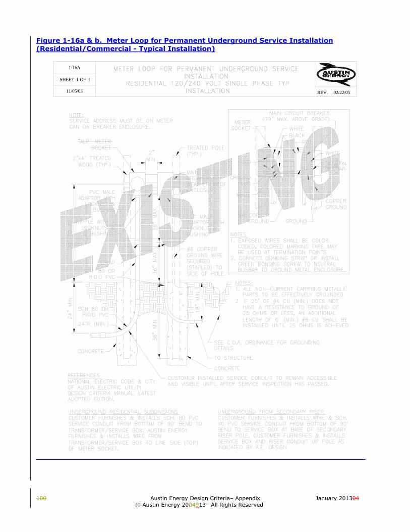
100 Austin Energy Design Criteria– Appendix January 201304
© Austin Energy 2004913– All Rights Reserved
Figure 1-16a & b. Meter Loop for Permanent Underground Service Installation (Residential/Commercial - Typical Installation)
SHEET OF
REV.
1-16A
1 1
11/05/03 02/22/05

January 201309 Austin Energy Design Criteria – Appendix 25 © Austin Energy 20131009 – All Rights Reserved
UNDERGROUND RESIDENTIAL SUBDIVISIONS:CUSTOMER FURNISHES & INSTALLS SCH. 80 PVCSERVICE CONDUIT FROM BOTTOM OF 90° BEND TOTRANSFORMER/SERVICE BOX. AUSTIN ENERGYFURNISHES & INSTALLS WIRE FROMTRANSFORMER/SERVICE BOX TO LINE SIDE (TOP) OFMETER SOCKET.
UNDERGROUND FROM SECONDARY RISER:CUSTOMER FURNISHES & INSTALLS WIRE & SCH. 40PVC SERVICE CONDUIT FROM BOTTOM OF 90° BEND TOSERVICE BOX AT BASE OF SECONDARY RISER POLE.CUSTOMER FURNISHES & INSTALLS SERVICE BOX ANDRISER CONDUIT UP POLE AS INDICATED BY A.E.DESIGN.
24"
MIN
.30
" TO
72"
NOTES:1. EXPOSED WIRES SHALL BE COLOR CODED, COLORED MARKING TAPE MAY BE USED AT TERMINATION POINTS.2. CONNECT BONDING STRAP OR INSTALL GREEN BONDING SCREW TO NEUTRAL BUSBAR TO GROUND METAL ENCLOSURE.
CUSTOMER INSTALLED SERVICE CONDUIT TO REMAIN ACCESSIBLE ANDVISIBLE UNTIL AFTER SERVICE INSPECTION HAS PASSED.
CONCRETE
18" M
IN.
24"R (MIN.)
SCH 80 ORRIGID PVC
SCH. 80 ORRIGID PVC
STRAP
PVC MALEADAPTOR WITH
LOCKNUT &BUSHING
"AE" METERSOCKET
2"x4" PRESSURETREATED
WOOD (TYP.)
2"MIN.
36"
MIN
.36
" M
AX
.36
" MA
X.
MAIN CIRCUITBREAKER INWEATHERPROOFENCLOSURE
PRESSURETREATED POLE(4" X 4" MIN.)
NIPPLE WITH 4LOCKNUTS & 2
BUSHINGS
PVC MALEADAPTOR WITHLOCKNUT &BUSHING
#6 COPPERGROUND WIRESECURED(STAPLED) TOSIDE OF POLE
SEE C.O.A. ORDINANCE FOR GROUNDINGDETAILS.
TO STRUCTURE
NOTES:1. ALL NON-CURRENT CARRYING METALLIC PARTS TO BE EFFECTIVELY BONDED.2. IF 25' OF #6 CU (MIN.) DOES NOT HAVE A RESISTANCE TO GROUND OF 25 OHMS OR LESS, AN ADDITIONAL LENGTH OF 6' (MIN.) #6 CU SHALL BE INSTALLED UNTIL 25 OHMS IS ACHIEVED.
REFERENCES:NATIONAL ELECTRIC CODE & CITYOF AUSTIN ELECTRIC UTILITYDESIGN CRITERIA MANUAL, LATESTADOPTED EDITION.
CONCRETE
METERSOCKET
RED
GROUNDLUG
REDBLACKWHITE
WHITE
NEUTRALBUSBAR
#6COPPERGROUND
#6 COPPERGROUND/BOND
MAIN CIRCUIT BREAKER (79"MAX. ABOVE GRADE)
WHITE
GROUND/BOND
NOTE:SERVICE ADDRESS MUST BE ON METER CANOR BREAKER ENCLOSURE.
SHEET OF
REV. 05/25/1210/16/03
11
1-16A

100 Austin Energy Design Criteria– Appendix January 201304
© Austin Energy 2004913– All Rights Reserved
SPOT LOCATORS
ELECTRIC PERMIT
ELECTRIC SERVICEAPPLICATION
METER LOOPINFORMATION
ELECTRIC SERVICEINSPECTION
ST. ELMO SERVICE CENTER4411-B MEINARDUS DRIVE505-7604 OR 505-7620
PERMIT & LICENSE CENTER301 W. 2ND ST. (1ST FLOOR)499-2380
ELECTRIC INSPECTION SECTION499-6476
UTILITY CUSTOMER SERVICECENTER476-7721
AUTOMATED TOUCH TONE, 24 HR.480-0623(FINAL ELECTRIC CODE-701)
REQUEST METER LOOP BEFORE STARTINGELECTRICAL INSTALLATION
OBTAIN AN ELECTRIC PERMIT BEFORE STARTINGELECTRICAL INSTALLATION.
CUSTOMER MUST APPLY FOR ELECTRIC SERVICEBEFORE ANY METER CAN BE ENERGIZED.
CALL FOR INFORMATION REGARDING METER LOOPINSTALLATION.
REQUEST INSPECTION AFTER ELECTRIC PERMIT HASBEEN OBTAINED, ALL FEES ARE PAID, AND ELECTRICINSTALLATION IS COMPLETE.
MATERIAL LIST FOR SERVICE ONLY. DOES NOT INCLUDE MATERIAL FROM MAIN CIRCUIT BREAKER TOSTRUCTURE. MATERIAL LIST IS APPROXIMATE AND FOR SUGGESTION ONLY. USE STRANDED ANDINSULATED WIRE IN CONDUIT. GROUND/BOND WIRE MAY BE NONINSULATED.
PRESSURE TREATED POSTMATERIALSQTY.
212'10'1111111142
1
10'40'
PRESSURE TREATED WOODSCH 80 PVC *SCH 80 PVC MALE ADAPTOR *SCH 80 PVC COUPLING *SCH 80 PVC 90° ELBOW *PVC STRAPLOCKNUT (METAL)PLASTIC BUSHINGMETER SOCKET (FURNISHED BY AE)4" LONG RIGID GALVANIZED NIPPLE xLOCKNUTS (METAL)PLASTIC BUSHING
MAIN CIRCUIT BREAKER IN WEATHERPROOFENCLOSURE
THHN/THWN COPPER WIRECOPPER GROUND WIRE-BARECONCRETE MIXCOLORED MARKING TAPE (eg. WHITE, RED)
SERVICE SIZE (AMPS): 100 125 150 175 200 225SIZE/SPECIFICATIONS4"x4" MIN. x 8' OR 10'
2"x4" MIN.
100 AMP
#4#6
1-1/4"150-S
2"2"2"2"2"2"2"
1-1/4"1-1/4"
TO FILL HOLES AROUND POLES (3' DEEP MIN.)TO MARK WIRE AT TERMINATION POINTS
SOUTH:ST. ELMO SERVICE CENTER4411-B MEINARDUS DRIVEDISPATCH OFFICE 505-7620
NORTH:KRAMER LANE SERVICE CENTER2526 KRAMER LANE, BLDG. "E"METER SHOP 505-7167
ELECTRIC SCH 80 PVC-GRAY COLORDOES NOT INCLUDE PVC FROM 90° BENDTO SERVICE BOX.WIRE FROM METER SOCKET TO MAINCIRCUIT BREAKER
125 AMP
1-1/4"150-S
2"2"2"2"2"2"2"
1-1/4"1-1/4"
#2#6
150 AMP
1-1/4"150-S
2"2"2"2"2"2"2"
1-1/4"1-1/4"
#1#6
175 AMP
200-S
2"2"2"2"2"2"2"
#1/0#6
200 AMP
200-S
2"2"2"2"2"2"2"
#2/0#6
225 AMP
200-S
2"2"2"2"2"2"2"
#3/0#6
2"2"2"
2"2"2"
2"2"2"
SHEET OF
REV.
1-16B
1 1
10/16/03 11/03/09

January 201309 Austin Energy Design Criteria – Appendix 27 © Austin Energy 20131009 – All Rights Reserved
SPOT LOCATORS
ELECTRIC PERMIT
ELECTRIC SERVICEAPPLICATION
METER LOOPINFORMATION
ELECTRIC SERVICEINSPECTION
ST. ELMO SERVICE CENTER4411-B MEINARDUS DRIVE505-7604 OR 505-7620
PERMIT & LICENSE CENTER505 BARTON SPRINGS RD.499-2380
ELECTRIC INSPECTION SECTION974-2027
UTILITY CUSTOMER SERVICECENTER476-7721
AUTOMATED TOUCH TONE, 24 HR.480-0623(FINAL ELECTRIC CODE-701)
REQUEST METER LOOP BEFORE STARTINGELECTRICAL INSTALLATION
OBTAIN AN ELECTRIC PERMIT BEFORE STARTINGELECTRICAL INSTALLATION.
CUSTOMER MUST APPLY FOR ELECTRIC SERVICEBEFORE ANY METER CAN BE ENERGIZED.
CALL FOR INFORMATION REGARDING METER LOOPINSTALLATION.
REQUEST INSPECTION AFTER ELECTRIC PERMIT HASBEEN OBTAINED, ALL FEES ARE PAID, AND ELECTRICINSTALLATION IS COMPLETE.
MATERIAL LIST FOR SERVICE ONLY. DOES NOT INCLUDE MATERIAL FROM MAIN CIRCUIT BREAKER TOSTRUCTURE. MATERIAL LIST IS APPROXIMATE AND FOR SUGGESTION ONLY. USE STRANDED ANDINSULATED WIRE IN CONDUIT. GROUND/BOND WIRE MAY BE NONINSULATED.
PRESSURE TREATED POSTMATERIALSQTY.
212'10'1111111142
1
10'40'
PRESSURE TREATED WOODSCH 80 PVC *SCH 80 PVC MALE ADAPTOR *SCH 80 PVC COUPLING *SCH 80 PVC 90° ELBOW *PVC STRAPLOCKNUT (METAL)PLASTIC BUSHINGMETER SOCKET (FURNISHED BY CUSTOMER)4" LONG RIGID GALVANIZED NIPPLE xLOCKNUTS (METAL)PLASTIC BUSHING
MAIN CIRCUIT BREAKER IN WEATHERPROOFENCLOSURE
THHN/THWN COPPER WIRECOPPER GROUND WIRE-BARECONCRETE MIXCOLORED MARKING TAPE (eg. WHITE, RED)
SERVICE SIZE (AMPS): 100 125 150 175 200 225SIZE/SPECIFICATIONS4"x4" MIN. x 8' OR 10'
2"x4" MIN.
100 AMP
#4#6
1-1/4"150-S
2"2"2"2"2"2"2"
1-1/4"1-1/4"
TO FILL HOLES AROUND POLES (3' DEEP MIN.)TO MARK WIRE AT TERMINATION POINTS
SOUTH:ST. ELMO SERVICE CENTER4411-B MEINARDUS DRIVEDISPATCH OFFICE 505-7620
NORTH:KRAMER LANE SERVICE CENTER2526 KRAMER LANE, BLDG. "E"METER SHOP 505-7167
ELECTRIC SCH 80 PVC-GRAY COLORDOES NOT INCLUDE PVC FROM 90° BENDTO SERVICE BOX.WIRE FROM METER SOCKET TO MAINCIRCUIT BREAKER
125 AMP
1-1/4"150-S
2"2"2"2"2"2"2"
1-1/4"1-1/4"
#2#6
150 AMP
1-1/4"150-S
2"2"2"2"2"2"2"
1-1/4"1-1/4"
#1#6
175 AMP
200-S
2"2"2"2"2"2"2"
#1/0#6
200 AMP
200-S
2"2"2"2"2"2"2"
#2/0#6
225 AMP
200-S
2"2"2"2"2"2"2"
#3/0#6
2"2"2"
2"2"2"
2"2"2"
SHEET OF
REV. 05/25/1210/16/03
11
1-16B

100 Austin Energy Design Criteria– Appendix January 201304
© Austin Energy 2004913– All Rights Reserved
Figure 1-17. Under Eaves Service Installation (Residential - Typical Overhead Installation)
PAGE
SHEET OF 1 1
XX/XX/XX
UNDERGROUND_EAVES_SERVICE_INSTALLATIONRESIDENTIAL_120/240_VOLT_SINGLE_PHASE_TYP_INSTALLATION
XX/XX/XXREV.

January 201309 Austin Energy Design Criteria – Appendix 29 © Austin Energy 20131009 – All Rights Reserved
2"MIN.
NOTES:1. ALL NON-CURRENT CARRYING METALLIC PARTS TO BE EFFECTIVELY BONDED.2. IF GROUND DOES NOT HAVE A RESISTANCE TO GROUND OF 25 OHMS OR LESS, AN ADDITIONAL LENGTH OF 6' MIN. OF #6 CU SHALL BE INSTALLED UNTIL 25 OHMS IS ACHIEVED.3. EXPOSED WIRES SHALL BE COLOR CODED, COLORED MARKING TAPE MAY BE USED AT TERMINATION POINTS.4. CONNECT BONDING STRAP OR INSTALL GREEN BONDING SCREW TO NEUTRAL BUSBAR TO GROUND METAL ENCLOSURE.
REFERENCES:NATIONAL ELECTRIC CODE& CITY OF AUSTINELECTRIC UTILITY DESIGNCRITERIA MANUAL,LATEST ADOPTED EDITION.
12" M
AX
.
24"
MA
X.
SERVICE DROP CONDUCTORSFURNISHED & INSTALLED BY
AUSTIN ENERGY(400 LB. MAX. TENSION)
ONE-POINT RACK:12'-6" MIN. TO 15' MAX. ABOVE
GRADE/GROUND. 16' MIN. TO 18'MAX. WHERE SERVICE DROP
CONDUCTORS ARE ABOVEAREAS SUBJECT TO VEHICULARTRAFFIC. ONE-POINT RACK NOTALLOWED TO BE ATTACHED TO
CONDUIT. RAINTIGHTCONNECTOR HUB(METAL)
30"
TO 7
2"
"AE" METER SOCKETTYPE 150-S: 150 AMP MAX.
TYPE 200-S: 175-225 AMP
CONDUIT-RIGID
SEE C.O.A. ORDINANCE FORGROUNDING DETAILS.
36"
MA
X.
36"
MA
X.
18" - #1/0 & SMALLER36" - #2/0 & LARGER
STRAP
GROUND/BOND
WHITERED
RED
MAIN CIRCUITBREAKER(79" MAX.ABOVE GRADE)
REDBLACK
WHITE
NEUTRALBUSBAR
COPPERGROUND WIRESTRAPPRD TOSURFACE OFBUILDING
COPPER GROUND WIREBONDED TO METAL
WATER PIPE
WEATHERHEAD (METAL)
STRAP
NOTE:SERVICE ADDRESS MUST BE ONMETER CAN OR BREAKERENCLOSURE.
WEATHERPROOFENCL. ON EXTERIOR
OF BUILDING
SHEET OF
REV. 05/25/1211/05/03
11
1-17

100 Austin Energy Design Criteria– Appendix January 201304
© Austin Energy 2004913– All Rights Reserved
Figure 1-18. Through Roof Service Mast Installation (Residential – Typical Overhead Installation)
1-18
SHEET 1 OF 1 1 1
11/05/03 02/22/05REV.

January 201309 Austin Energy Design Criteria – Appendix 31 © Austin Energy 20131009 – All Rights Reserved
NOTES:1. ALL NON-CURRENT CARRYING METALLIC PARTS TO BE EFFECTIVELY BONDED.2. IF GROUND DOES NOT HAVE A RESISTANCE TO GROUND OF 25 OHMS OR LESS, AN ADDITIONAL LENGTH OF 6' MIN. OF #6 CU SHALL BE INSTALLED UNTIL 25 OHMS IS ACHIEVED.3. EXPOSED WIRES SHALL BE COLOR CODED, COLORED MARKING TAPE MAY BE USED AT TERMINATION POINTS.4. CONNECT BONDING STRAP OR INSTALL GREEN BONDING SCREW TO NEUTRAL BUSBAR TO GROUND METAL ENCLOSURE.5. NO FITTINGS, SUCH AS COUPLINGS, MAY BE LOCATED BETWEEN THE ROOF AND POINT OF ATTACHMENT (ONE POINT RACK).6. WHEN GUYING IS REQUIRED A 3/16" X 1" COMMON GALVANIZED PIPE BAND AND 1/4" THIMBLE SHALL BEATTACHED BELOW THE SERVICE ATTACHMENT POINT. 1/4" COMMON GALVANIZED STEEL STRAND OREQUAL SHALL BE INSTALLEDAT A 45° ANGLE TO ROOF. (2 GUYS REQUIRED) THE GUYS SHALL ATTACH TOROOF WITH ROOF PLATE BOLTED TO ROOF RAFTERS. 1/4" THIMBLE AND GUY CLAMP SHALL BE USED TOATTACH GUY WIRE TO ROOF PLATE. EYE BOLTS AND WASHERS ARE ACCEPTABLE FOR GUY PLATE GUYWIRE ATTACHMENT. EYE LAGS ARE NOT ACCEPTABLE.
REFERENCES:NATIONAL ELECTRIC CODE & CITYOF AUSTIN ELECTRIC UTILITYDESIGN CRITERIA MANUAL, LATESTADOPTED EDITION.
SERVICE DROP CONDUCTORSFURNISHED & INSTALLED BY
AUSTIN ENERGY NO MORETHAN 6' PASS OVER 4' OF ROOF
SURFACE, MEASUREDHORIZONTALLY.
30" T
O 7
2"
"AE" METER SOCKETTYPE 150-S: 150 AMP MAX.
TYPE 200-S: 175-225 AMP
SEE C.O.A. ORDINANCE FORGROUNDING DETAILS.
18"-#1/0 & SMALLER36"-#2/0 & LARGER
GROUND/BOND
WHITE
RED
BLACK
MAIN CIRCUITBREAKER(79" MAX. ABOVEGRADE)
RED
WHITE
NEUTRALBUSBAR
COPPERGROUND WIRESTRAPPED TOSURFACE OFBUILDING
WEATHERHEAD (METAL)
STRAP
ONE-POINT RACK (CLAMP ON):12'-6" MIN. TO 15' MAX. ABOVE
GRADE/GROUND. 16' MIN. TO 18' MAX.WHERE SERVICE DROP CONDUCTORS ARE
ABOVE AREAS SUBJECT TO VEHICULARTRAFFIC. POINT OF ATTACHMENT TO
WITHSTAND 400 LBS. TENSION.
RAINTIGHTCONNECTORHUB (METAL)
CONDUIT-2" MIN RIGIDSTRAP
18"
MIN
.12
"M
AX
.
SERVICE MAST MORETHAN 4' ABOVE ROOFMUST BE GUYED - SEENOTE 6.
ROOF SLOPE NOT LESSTHAN 4" IN 12"
WEATERPROOFENCLOSURE ON
EXTERIOR OFBUILDING
COPPERGROUND WIREBONDED TOMETAL WATERPIPE
NOTE:SERVICE ADDRESS MUST BE ONMETER CAN OR BREAKERENCLOSURE.
4' MAX.
36"
MA
X.
2"MIN.
SHEET OF
REV. 05/25/1211/05/03
11
1-18

100 Austin Energy Design Criteria– Appendix January 201304
© Austin Energy 2004913– All Rights Reserved
Figure 1-19. Underground Service Installation (Residential - Typical Installation)
UNDERGROUND RESIDENTIAL SUBDIVISIONS:CUSTOMER FURNISHES & INSTALLS SCH. 80 PVCSERVICE CONDUIT FROM BOTTOM OF 90° BEND TOTRANSFORMER/SERVICE BOX. AUSTIN ENERGYFURNISHES & INSTALLS WIRE FROMTRANSFORMER/SERVICE BOX TO LINE SIDE (TOP) OFMETER SOCKET.
UNDERGROUND FROM SECONDARY RISER:CUSTOMER FURNISHES & INSTALLS WIRE & SCH. 40PVC SERVICE CONDUIT FROM BOTTOM OF 90° BEND TOSERVICE BOX AT BASE OF SECONDARY RISER POLE.CUSTOMER FURNISHES & INSTALLS SERVICE BOX ANDRISER CONDUIT UP POLE AS INDICATED BY A.E.DESIGN.
2"MIN.
SEE C.O.A. ORDINANCE FORGROUNDING DETAILS.
NOTES:1. ALL NON-CURRENT CARRYING METALLIC PARTS TO BE EFFECTIVELY BONDED.2. IF GROUND DOES NOT HAVE A RESISTANCE TO GROUND OF 25 OHMS OR LESS, AN ADDITIONAL LENGTH OF #6 CU SHALL BE INSTALLED 6' (MIN.) UNTIL 25 OHMS IS ACHIEVED.3. EXPOSED WIRES SHALL BE COLOR CODED, COLORED MARKING TAPE MAY BE USED AT TERMINATION POINTS.4. CONNECT BONDING STRAP OR INSTALL GREEN BONDING SCREW TO NEUTRAL BUSBAR TO GROUND METAL ENCLOSURE.5. SERVICE ADDRESS MUST BE ON METER CAN OR BREAKER ENCLOSURE.
"AE" METER SOCKETTYPE 150-S: 150 AMP MAX.
TYPE 200-S: 175-225 AMP
30" T
O 7
2"
MAIN CIRCUIT BREAKER(79" MAX. ABOVEGRADE)
COPPER GROUNDWIRE BONDED TOMETAL WATER PIPE
COPPER GROUNDWIRE STRAPPED TOSURFACE OFBUILDING
NEUTRALBUSBAR
WHITE
RED
RED
WHITE
GROUND
24" M
IN.
36"
MA
X.
36" M
AX
.
STRAP
SCH 80 PVC ORRIGID
24"R MIN.
CUSTOMER INSTALLED SERVICE CONDUIT TOREMAIN ACCESSIBLE AND VISIBLE UNTIL AFTERSERVICE INSPECTION HAS PASSED.
BLACK
WEATERPROOFENCLOSURE ONEXTERIOR OF BUILDING
REFERENCES:NATIONAL ELECTRIC CODE & CITY OFAUSTIN ELECTRIC UTILITY DESIGNCRITERIA MANUAL, LATEST ADOPTEDEDITION.
SHEET OF
REV. 02/22/0511/05/03
11
1-19

January 201309 Austin Energy Design Criteria – Appendix 33 © Austin Energy 20131009 – All Rights Reserved
UNDERGROUND RESIDENTIAL SUBDIVISIONS:CUSTOMER FURNISHES & INSTALLS SCH. 80 PVCSERVICE CONDUIT FROM BOTTOM OF 90° BEND TOTRANSFORMER/SERVICE BOX. AUSTIN ENERGYFURNISHES & INSTALLS WIRE FROMTRANSFORMER/SERVICE BOX TO LINE SIDE (TOP) OFMETER SOCKET.
UNDERGROUND FROM SECONDARY RISER:CUSTOMER FURNISHES & INSTALLS WIRE & SCH. 40PVC SERVICE CONDUIT FROM BOTTOM OF 90° BEND TOSERVICE BOX AT BASE OF SECONDARY RISER POLE.CUSTOMER FURNISHES & INSTALLS SERVICE BOX ANDRISER CONDUIT UP POLE AS INDICATED BY A.E.DESIGN.
2"MIN.
SEE C.O.A. ORDINANCE FORGROUNDING DETAILS.
NOTES:1. ALL NON-CURRENT CARRYING METALLIC PARTS TO BE EFFECTIVELY BONDED.2. IF GROUND DOES NOT HAVE A RESISTANCE TO GROUND OF 25 OHMS OR LESS, AN ADDITIONAL LENGTH OF #6 CU SHALL BE INSTALLED 6' (MIN.) UNTIL 25 OHMS IS ACHIEVED.3. EXPOSED WIRES SHALL BE COLOR CODED, COLORED MARKING TAPE MAY BE USED AT TERMINATION POINTS.4. CONNECT BONDING STRAP OR INSTALL GREEN BONDING SCREW TO NEUTRAL BUSBAR TO GROUND METAL ENCLOSURE.5. SERVICE ADDRESS MUST BE ON METER CAN OR BREAKER ENCLOSURE.
"AE" METER SOCKETTYPE 150-S: 150 AMP MAX.
TYPE 200-S: 175-225 AMP
30"
TO 7
2"
MAIN CIRCUIT BREAKER(79" MAX. ABOVEGRADE)
COPPER GROUNDWIRE BONDED TOMETAL WATER PIPE
COPPER GROUNDWIRE STRAPPED TOSURFACE OFBUILDING
NEUTRALBUSBAR
WHITE
RED
RED
WHITE
GROUND/BOND
24"
MIN
.
36"
MA
X.
36" M
AX
.
STRAP
SCH 80 PVC ORRIGID
24"R MIN.
CUSTOMER INSTALLED SERVICE CONDUIT TOREMAIN ACCESSIBLE AND VISIBLE UNTIL AFTERSERVICE INSPECTION HAS PASSED.
BLACK
WEATERPROOFENCLOSURE ONEXTERIOR OF BUILDING
REFERENCES:NATIONAL ELECTRIC CODE & CITY OFAUSTIN ELECTRIC UTILITY DESIGNCRITERIA MANUAL, LATEST ADOPTEDEDITION.
SHEET OF
REV. 05/25/1211/05/03
11
1-19

100 Austin Energy Design Criteria– Appendix January 201304
© Austin Energy 2004913– All Rights Reserved
Figure 1-20. Meter Loop for Permanent Overhead Service Installation (Commercial - Typical Installation)
1-20
SHEET 1 OF 1 1 1
11/05/03 02/22/05REV.
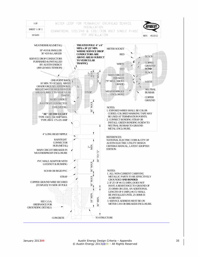
January 201309 Austin Energy Design Criteria – Appendix 35 © Austin Energy 20131009 – All Rights Reserved
NOTES:1. EXPOSED WIRES SHALL BE COLOR CODED, COLORED MARKING TAPE MAY BE USED AT TERMINATION POINTS.2. CONNECT BONDING STRAP OR INSTALL GREEN BONDING SCREW TO NEUTRAL BUSBAR TO GROUND METAL ENCLOSURE.
COPPERGROUND
WEATHERPROOFENCLOSURE
MAIN CIRCUITBREAKER
(79" MAX. ABOVEGRADE)
RED
WHITE
RED
METER SOCKET
NEUTRALBUSBAR
BLACK
BLACK
36"
MA
X.
36" M
AX
.
36"
MIN
.30
" TO
72"
ONE-POINT RACK:16' MIN. TO 18' MAX. ABOVE
GRADE/GROUND. ADDITIONALHEIGHT MAY BE REQUIRED FORAREAS SUBJECT TO VEHICULAR
TRAFFIC.
REFERENCES:NATIONAL ELECTRIC CODE & CITY OFAUSTIN ELECTRIC UTILITY DESIGNCRITERIA MANUAL, LATEST ADOPTEDEDITION.
NOTES:1. ALL NON-CURRENT CARRYING METALLIC PARTS TO BE EFFECTIVELY GROUNDED AND BONDED.2. IF 25' OF #6 CU (MIN.) DOES NOT HAVE A RESISTANCE TO GROUND OF 25 OHMS OR LESS, AN ADDITIONAL LENGTH OF 6' (MIN.) #6 CU SHALL BE INSTALLED UNTIL 25 OHMS IS ACHIEVED.3. SERVICE ADDRESS MUST BE ON METER CAN OR BREAKER ENCLOSURE.
WHITE
COPPERGROUND/BOND
2" MIN
.12
"M
AX
.36
" MA
X.
36"
MA
X.
STRAP
HUB (METAL)
"AE" METER SOCKETTYPE 150-S: 150 AMP MAX.
TYPE 200-S: 175-225 AMP
RAINTIGHT CONNECTORRIGID CONDUIT
SERVICE DROP CONDUCTORSFURNISHED & INSTALLED
BY AUSTIN ENERGY(400 LB MAX TENSION)
18"-#1/0 & SMALLER36"-#2/0 & LARGER
TREATED POLE 6" x 6"MIN) x 20' (22' MIN.WHERE SERVICE DROPCONDUCTORS AREABOVE AREAS SUBJECTTO VEHICULARTRAFFIC)
4" LONG RIGID NIPPLE
RAINTIGHTCONNECTORHUB (METAL)
MAIN CIRCUIT BREAKER INWEATHERPROOF ENCLOSURE
PVC MALE ADAPTOR WITHLOCKNUT & BUSHING
STRAP
SCH 80 OR RIGID PVC
COPPER GROUND WIRE SECURED(STAPLED) TO SIDE OF POLE
SEE C.O.A.ORDINANCE FOR
GROUNDING DETAILS.
TO STRUCTURECONCRETE
18"
MIN
.
WEATHERHEAD (METAL)
SHEET OF
REV. 05/25/1210/16/03
11
1-20

100 Austin Energy Design Criteria– Appendix January 201304
© Austin Energy 2004913– All Rights Reserved
Figure 1-21. Under Eaves Service Installation (Commercial - Typical Installation)
1-21
SHEET 1 OF 1 1 1
11/05/03 02/22/05REV.

January 201309 Austin Energy Design Criteria – Appendix 37 © Austin Energy 20131009 – All Rights Reserved
2"MIN.
NOTES:1. ALL NON-CURRENT CARRYING METALLIC PARTS TO BE EFFECTIVELY GROUNDED AND BONDED.2. IF 25' OF #6 CU (MIN.) DOES NOT HAVE A RESISTANCE TO GROUND OF 25 OHMS OR LESS, AN ADDITIONAL LENGTH OF 6' MIN. OF #6 CU SHALL BE INSTALLED UNTIL 25 OHMS IS ACHIEVED.3. EXPOSED WIRES SHALL BE COLOR CODED, COLORED MARKING TAPE MAY BE USED AT TERMINATION POINTS.4. CONNECT BONDING STRAP OR INSTALL GREEN BONDING SCREW TO NEUTRAL BUSBAR TO GROUND METAL ENCLOSURE.5. SERVICE ADDRESS MUST BE ON METER CAN OR BREAKER ENCLOSURE.
REFERENCES:NATIONAL ELECTRIC CODE & CITY OFAUSTIN ELECTRIC UTILITY DESIGN CRITERIAMANUAL, LATEST ADOPTED EDITION.
12"
MA
X.
24" M
IN.
SERVICE DROP CONDUCTORSFURNISHED & INSTALLED BY
AUSTIN ENERGY(400 LB. MAX. TENSION)
ONE-POINT RACK:16' MIN. TO 18' MAX. ABOVE
GRADE/GROUND. 18' MIN. TO 21'MAX. WHERE SERVICE DROP
CONDUCTORS ARE ABOVEAREAS SUBJECT TO
VEHICULAR TRAFFIC.ONE-POINT RACK NOT
ALLOWED TO BE ATTACHEDTO CONDUIT.
RAINTIGHTCONNECTORHUB (METAL)
30" T
O 7
2"
"AE" METER SOCKETTYPE 150-S: 150 AMP MAX.
TYPE 200-S: 175-225 AMP
SEE C.O.A. ORDINANCE FORGROUNDING DETAILS.
36"
MA
X.
36"
MA
X.
STRAP (TYP.)
GROUND/BOND
WHITE
RED
WEATHERPROOFENCLOSURE ONEXTERIORSURFACE OFBUILDING
MAIN CIRCUITBREAKER(79" MAX. ABOVEGRADE)
REDBLACK
WHITE
NEUTRALBUSBAR
COPPERGROUND WIRESTRAPPRD TOSURFACE OFBUILDING
COPPER GROUNDWIRE BONDED TO
METAL WATER PIPE
WEATHERHEAD (METAL)
STRAP
18"-#1/0 & SMALLER36"-#2/0 & LARGER
CONDUIT-RIGID
SHEET OF
REV. 05/25/1210/16/03
11
1-21

100 Austin Energy Design Criteria– Appendix January 201304
© Austin Energy 2004913– All Rights Reserved
Figure 1-22. Through Roof Service Mast Installation (Commercial - Typical Installation)
1-22
SHEET 1OF 1 1 1
11/05/03 03/03/09REV.

January 201309 Austin Energy Design Criteria – Appendix 39 © Austin Energy 20131009 – All Rights Reserved
NOTES:1. ALL NON-CURRENT CARRYING METALLIC PARTS TO BE EFFECTIVELY GROUNDED AND BONDED.2. IF 25' OF #6 CU (MIN.) DOES NOT HAVE A RESISTANCE TO GROUND OF 25 OHMS OR LESS, AN ADDITIONAL LENGTH OF 6' MIN. OF #6 CU SHALL BE INSTALLED UNTIL 25 OHMS IS ACHIEVED.3. EXPOSED WIRES SHALL BE COLOR CODED, COLORED MARKING TAPE MAY BE USED AT TERMINATION POINTS.4. CONNECT BONDING STRAP OR INSTALL GREEN BONDING SCREW TO NEUTRAL BUSBAR TO GROUND METAL ENCLOSURE.5. NO FITTINGS, SUCH AS COUPLINGS, MAY BE LOCATED BETWEEN THE ROOF AND POINT OF ATTACHMENT (ONE POINT RACK).6. WHEN GUYING IS REQUIRED A 3/16" X 1" COMMON GALVANIZED PIPE BAND AND 1/4" THIMBLE SHALL BEATTACHED BELOW THE SERVICE ATTACHMENT POINT. 1/4" COMMON GALVANIZED STEEL STRAND OREQUAL SHALL BE INSTALLEDAT A 45° ANGLE TO ROOF. (2 GUYS REQUIRED) THE GUYS SHALL ATTACH TOROOF WITH ROOF PLATE BOLTED TO ROOF RAFTERS. 1/4" THIMBLE AND GUY CLAMP SHALL BE USED TOATTACH GUY WIRE TO ROOF PLATE. EYE BOLTS AND WASHERS ARE ACCEPTABLE FOR GUY PLATE GUYWIRE ATTACHMENT. EYE LAGS ARE NOT ACCEPTABLE.
REFERENCES:NATIONAL ELECTRIC CODE &CITY OF AUSTIN ELECTRICUTILITY DESIGN CRITERIAMANUAL, LATEST ADOPTEDEDITION.
SERVICE DROP CONDUCTORSFURNISHED & INSTALLED BY
AUSTIN ENERGY. NO MORETHAN 6' PASS OVER 4' OF ROOF
SURFACE, MEASUREDHORIZONTALLY.
30"
TO 7
2"
"AE" METER SOCKETTYPE 150-S: 150 AMP MAX.
TYPE 200-S: 175-225 AMP
SEE C.O.A. ORDINANCE FORGROUNDING DETAILS.
18"-#1/0 & SMALLER36"-#2/0 & LARGER
GROUND/BOND
WHITERED
BLACK
MAIN CIRCUITBREAKER(79" MAX.ABOVE GRADE)
RED
WHITE
NUETRALBUSBAR
COPPERGROUND WIRESTRAPPED TOSURFACE OFBUILDING
WEATHERHEAD (METAL)
STRAP
ONE-POINT RACK (CLAMP ON):16' MIN. TO 18' MAX. ABOVE GRADE/GROUND.18' MIN. TO 21' MAX. WHERE SERVICE DROPCONDUCTORS ARE ABOVE AREAS SUBJECTTO VEHICULAR TRAFFIC. POINT OFATTACHMENT TO WITHSTAND 400 LBS.TENSION-GUY WIRE MAY BE NECESSARY.SEE NOTE 6 BELOW..
RAINTIGHTCONNECTOR
HUB (METAL)
CONDUIT-2" MIN RIGIDSTRAP
18"
12"
MA
X.
SERVICE MAST MORETHAN 4' ABOVE ROOFMUST BE GUYED
ROOF SLOPE NOT LESSTHAN 4" IN 12"
WEATERPROOFENCLOSURE ON
EXTERIOR OFBUILDING
COPPERGROUND WIREBONDED TOMETAL WATERPIPE
NOTE:SERVICE ADDRESS MUST BE ONMETER CAN OR BREAKERENCLOSURE.
4' MAX.
36"
MA
X.
2"MIN.
SHEET OF
REV. 05/25/1210/16/03
11
1-22

100 Austin Energy Design Criteria– Appendix January 201304
© Austin Energy 2004913– All Rights Reserved
Figure 1-23. Underground Service Installation (Commercial - Typical Installation)
UNDERGROUND FROM SERVICE POINT (TRANSFORMER, SERVICE BOX, PULLBOX) TO METER:CUSTOMER FURNISHES & INSTALLS WIRE & SERVICE CONDUIT FROM METER TO SERVICE POINT.
2"MIN.
MIN. 25' #6 CU SOLID WIRE. SEEC.O.A. ORDINANCE FORGROUNDING DETAILS.
NOTES:1. ALL NON-CURRENT CARRYING METALLIC PARTS TO BE EFFECTIVELY GROUNDED.2. IF 25' OF #6 CU (MIN.) DOES NOT HAVE A RESISTANCE TO GROUND OF 25 OHMS OR LESS, AN ADDITIONAL LENGTH OF 6' (MIN.) #6 CU SHALL BE INSTALLED UNTIL 25 OHMS IS ACHIEVED.3. EXPOSED WIRES SHALL BE COLOR CODED, COLORED MARKING TAPE MAY BE USED AT TERMINATION POINTS.4. CONNECT BONDING STRAP OR INSTALL GREEN BONDING SCREW TO NEUTRAL BUSBAR TO GROUND METAL ENCLOSURE.5. SERVICE ADDRESS MUST BE ON METER CAN OR BREAKER ENCLOSURE.
"AE" METER SOCKETTYPE 150-S: 150 AMP MAX.
TYPE 200-S: 175-225 AMP
30"
TO 7
2"
MAIN CIRCUIT BREAKER(79" MAX. ABOVEGRADE)
COPPER GROUNDWIRE BONDED TOMETAL WATER PIPE
COPPER GROUNDWIRE STRAPPED TOSURFACE OFBUILDING
NEUTRAL BUSBAR
WHITE
RED
RED
WHITE
GROUND
24"
MIN
.
36" M
AX
.36
" MA
X.
STRAP
SCH 80 PVC ORRIGID
24"R MIN.
CUSTOMER INSTALLED SERVICE CONDUIT TOREMAIN ACCESSIBLE AND VISIBLE UNTIL AFTERSERVICE INSPECTION HAS PASSED.
BLACK
WEATERPROOFENCLOSURE ONEXTERIOR OF BUILDING
REFERENCES:NATIONAL ELECTRIC CODE & CITY OFAUSTIN ELECTRIC UTILITY DESIGNCRITERIA MANUAL, LATEST ADOPTEDEDITION.
SHEET OF
REV. 02/22/0511/05/03
11
1-23

January 201309 Austin Energy Design Criteria – Appendix 41 © Austin Energy 20131009 – All Rights Reserved
UNDERGROUND FROM SERVICE POINT (TRANSFORMER, SERVICE BOX, PULLBOX) TO METER:CUSTOMER FURNISHES & INSTALLS WIRE & SERVICE CONDUIT FROM METER TO SERVICE POINT.
2"MIN.
MIN. 25' #6 CU SOLID WIRE. SEEC.O.A. ORDINANCE FORGROUNDING DETAILS.
NOTES:1. ALL NON-CURRENT CARRYING METALLIC PARTS TO BE EFFECTIVELY BONDED.2. IF 25' OF #6 CU (MIN.) DOES NOT HAVE A RESISTANCE TO GROUND OF 25 OHMS OR LESS, AN ADDITIONAL LENGTH OF 6' (MIN.) #6 CU SHALL BE INSTALLED UNTIL 25 OHMS IS ACHIEVED.3. EXPOSED WIRES SHALL BE COLOR CODED, COLORED MARKING TAPE MAY BE USED AT TERMINATION POINTS.4. CONNECT BONDING STRAP OR INSTALL GREEN BONDING SCREW TO NEUTRAL BUSBAR TO GROUND METAL ENCLOSURE.5. SERVICE ADDRESS MUST BE ON METER CAN OR BREAKER ENCLOSURE.
"AE" METER SOCKETTYPE 150-S: 150 AMP MAX.
TYPE 200-S: 175-225 AMP
30"
TO 7
2"
MAIN CIRCUIT BREAKER(79" MAX. ABOVEGRADE)
COPPER GROUNDWIRE BONDED TOMETAL WATER PIPE
COPPER GROUNDWIRE STRAPPED TOSURFACE OFBUILDING
NEUTRAL BUSBAR
WHITE
RED
RED
WHITE
GROUND/BOND
24" M
IN.
36" M
AX
.36
" M
AX
.
STRAP
SCH 80 PVC ORRIGID
24"R MIN.
CUSTOMER INSTALLED SERVICE CONDUIT TOREMAIN ACCESSIBLE AND VISIBLE UNTIL AFTERSERVICE INSPECTION HAS PASSED.
BLACK
WEATERPROOFENCLOSURE ONEXTERIOR OF BUILDING
REFERENCES:NATIONAL ELECTRIC CODE & CITY OFAUSTIN ELECTRIC UTILITY DESIGNCRITERIA MANUAL, LATEST ADOPTEDEDITION.
SHEET OF
REV.
1-23
1 1
10/16/03 05/25/12

100 Austin Energy Design Criteria– Appendix January 201304
© Austin Energy 2004913– All Rights Reserved
Figure 1-24. Two-Meter Permanent Overhead Installation (Typical Installation)
1-24
SHEET 1OF 1 1 1
11/05/03 02/22/05REV.

January 201309 Austin Energy Design Criteria – Appendix 43 © Austin Energy 20131009 – All Rights Reserved
NOTES:1. 3/16" DIAMETER HOLE DRILLED FOR AUSTIN ENERGY TO INSTALL UTILITY SEAL.2. THE SERVICE DISTRIBUTION ENCLOSURE SHALL BE EITHER A BUS ENCLOSURE WITH A MAXIMUM 2500 AMP SERVICE SIZE OR A JUNCTION BOX WITH A MAXIMUM 1200 AMP SERVICE SIZE. THE JUNCTION BOX SHALL BE EQUIPPED WITH TERMINAL BLOCKS AND SIZED ACCORDING TO THE TABLE "JUNCTION BOX AND WIREWAY SPECIFICATIONS" IN APPENDIX C. THE 1200 AMP MAXIMUM DOES NOT APPLY TO RESIDENTIAL INSTALLATIONS.3. SERVICE RISER CONDUIT SHALL BE RIGID METAL. (IMC, OR EMT - EMT NOT PERMITTED FOR SERVICE MAST THROUGH ROOF.) THROUGH ROOF MUST BE RIGID METAL.
NOTE:SERVICE ADDRESS MUST BE ONMETER CAN OR BREAKERENCLOSURE.
NOTES:1. ALL NON-CURRENT CARRYING METALLIC PARTS TO BE EFFECTIVELY GROUNDED AND BONDED.2. EXPOSED WIRES SHALL BE COLOR CODED, COLORED MARKING TAPE MAY BE USED AT TERMINATION POINTS.3. CONNECT BONDING STRAP OR INSTALL GREEN BONDING SCREW TO NEUTRAL BUSBAR TO GROUND METAL ENCLOSURE.4. THE GROUNDING AND BONDING WIRE FOR THE SERVICE SHALL TERMINATE IN SERVICE DISTRIBUTION ENCLOSURE.
MAIN SERVICE DISCONNECTWEATERPROOF ENCLOSURE
"AE" METER SOCKET
STRAP
SEE NOTE 1 (TYP.)
ONE POINT RACK:RESIDENTIAL- 12'6" MIN. TO 15' MAX.COMMERCIAL- 16' MIN. TO 18' MAX.(ADDITIONAL HEIGHT MAY BE REQUIRED FORAREAS SUBJECT TO VEHICULAR TRAFFIC.)
30"-
72"
12"-
66" 2"
MIN.(TYP.)
2"MIN.
(TYP.)
SEE NOTE 2
COPPER GROUND WIRE STRAPPED TO SURFACEOF BUILDING
CONTINUOUS GROUND WIRE FROM GROUNDROD THRU LOG TO NEUTRAL TERMINAL BLOCK(MOUNT LUGS WITH BOLT AND NUT)
COPPER GROUND/BONDWIRE CONNECTED TO
METAL WATER PIPE (TYP.)
WHITE (TYP.)GROUND/BOND (TYP.)
MAIN CIRCUIT BREAKER(TYP.)
(79" MAX. ABOVE GRADE)
RED (TYP.)
BLACKBLACK
REDWHITE
BLACKSEE NOTE 3
18"-#1/0 & SMALLER36"-#2/0 & LARGER
NEUTRAL BUSBAR (TYP.)
REFERENCES:NATIONAL ELECTRIC CODE & CITYOF AUSTIN ELECTRIC UTILITYDESIGN CRITERIA MANUAL, LATESTADOPTED EDITION.
SEE C.O.A. ORDINANCE FOR GROUNDINGDETAILS.
36"
MA
X.
36"
MA
X.
RAINTIGHTCONNECTORHUB(METAL)
SHEET OF
REV.
1-24
1 1
10/16/03 05/25/12

100 Austin Energy Design Criteria– Appendix January 201304
© Austin Energy 2004913– All Rights Reserved
NOTES:1. 3/16" DIAMETER HOLE DRILLED FOR AUSTIN ENERGY TO INSTALL UTILITY SEAL.2. THE SERVICE DISTRIBUTION ENCLOSURE SHALL BE EITHER A BUS ENCLOSURE WITH A MAXIMUM 2500 AMP SERVICE SIZE OR A JUNCTION BOX WITH A MAXIMUM 1200 AMP SERVICE SIZE. THE JUNCTION BOX SHALL BE EQUIPPED WITH TERMINAL BLOCKS AND SIZED ACCORDING TO THE TABLE "JUNCTION BOX AND WIREWAY SPECIFICATIONS" IN APPENDIX C. THE 1200 AMP MAXIMUM DOES NOT APPLY TO RESIDENTIAL INSTALLATIONS.3. UNDERGROUND RESIDENTIAL: CUSTOMER FURNISHES & INSTALLS SCH. 80 PVC SERVICE CONDUIT FROM BOTTOM OF 90° TO TRANSFORMER/SERVICE BOX. UNDERGROUND COMMERCIAL: CUSTOMER FURNISHES & INSTALLS SERVICE CONDUIT & LATERAL CONDUCTORS FROM METER BASE/SERVICE DISTRIBUTION ENCLOSURE TO TRANSFORMER/POINT OF SERVICE. (THE 90° BEND AND THE CONDUIT UP TO THE METER BASE/SERVICE DISTRIBUTION ENCLOSURE SHALL BE SCH 80 PVC OR RIGID METAL. THE CONDUIT FROM THE BOTTOM OF 90° BEND TO TRANSFORMER/SERVICE BOX SHALL BE SCH 40 PVC.)
NOTE:SERVICE ADDRESS MUST BE ONMETER CAN OR BREAKERENCLOSURE.
SEE NOTE 2
COPPER GROUND WIRE STRAPPEDTO SURFACE OF BUILDING
CONTINUOUS GROUND WIRE FROM GROUNDROD THRU LOG TO NEUTRAL TERMINAL BLOCK(MOUNT LUGS WITH BOLT AND NUT)
30"-
72"
12"-
44" 2" MIN. (TYP.)
2" MIN. (TYP.)
24"
MIN
.
36"
MA
X.
36"
MA
X.
SEE NOTE 3
MAIN SERVICE DISCONNECTWEATHERPROOF ENCLOSURE
SEE NOTE 1 (TYP)
"ALP" METER SOCKET
STRAP
NOTES:1. ALL NON-CURRENT CARRYING METALLIC PARTS TO BE EFFECTIVELY GROUNDED.2. IF GROUND DOES NOT HAVE A RESISTANCE TO GROUND OF 25 OHMS OR LESS, AN ADDITIONAL LENGTH OF 6' MIN. OF #6 CU SHALL BE INSTALLED UNTIL 25 OHMS IS ACHIEVED.3. EXPOSED WIRES SHALL BE COLOR CODED, COLORED MARKING TAPE MAY BE USED AT TERMINATION POINTS.4. CONNECT BONDING STRAP OR INSTALL GREEN BONDING SCREW TO NEUTRAL BUSBAR TO GROUND METAL ENCLOSURE.5. THE GROUNDING AND BONDING WIRE FOR THE SERVICE SHALL TERMINATE IN THE SERVICE DISTRIBUTION ENCLOSURE.
REFERENCES:NATIONAL ELECTRIC CODE & CITYOF AUSTIN ELECTRIC UTILITYDESIGN CRITERIA MANUAL, LATESTADOPTED EDITION. MIN. 25' #6 CU SOLID WIRE. SEE C.O.A.
ORDINANCE FOR GROUNDING DETAILS.
SEE NOTE 4BLACKRED WHITE
BLACKRED
BLACK
MAIN CIRCUIT BREAKER(TYP.)(79" MAX. ABOVE
GRADE)
NEUTRAL BUSBAR (TYP.)
GROUND (TYP.)
WHITE (TYP.)
COPPER GROUND WIRECONNECTED TO METAL
WATER PIPE (TYP.)
SHEET OF
REV. 02/22/0511/05/03
11
1-25

January 201309 Austin Energy Design Criteria – Appendix 45 © Austin Energy 20131009 – All Rights Reserved
Figure 1-25. Two-Meter Permanent Underground Installation (Typical Installation)
NOTES:1. 3/16" DIAMETER HOLE DRILLED FOR AUSTIN ENERGY TO INSTALL UTILITY SEAL.2. THE SERVICE DISTRIBUTION ENCLOSURE SHALL BE EITHER A BUS ENCLOSURE WITH A MAXIMUM 2500 AMP SERVICE SIZE OR A JUNCTION BOX WITH A MAXIMUM 1200 AMP SERVICE SIZE. THE JUNCTION BOX SHALL BE EQUIPPED WITH TERMINAL BLOCKS AND SIZED ACCORDING TO THE TABLE "JUNCTION BOX AND WIREWAY SPECIFICATIONS" IN APPENDIX C. THE 1200 AMP MAXIMUM DOES NOT APPLY TO RESIDENTIAL INSTALLATIONS.3. UNDERGROUND RESIDENTIAL: CUSTOMER FURNISHES & INSTALLS SCH. 80 PVC SERVICE CONDUIT FROM BOTTOM OF 90° TO TRANSFORMER/SERVICE BOX. UNDERGROUND COMMERCIAL: CUSTOMER FURNISHES & INSTALLS SERVICE CONDUIT & LATERAL CONDUCTORS FROM METER BASE/SERVICE DISTRIBUTION ENCLOSURE TO TRANSFORMER/POINT OF SERVICE. (THE 90° BEND AND THE CONDUIT UP TO THE METER BASE/SERVICE DISTRIBUTION ENCLOSURE SHALL BE SCH 80 PVC OR RIGID METAL. THE CONDUIT FROM THE BOTTOM OF 90° BEND TO TRANSFORMER/SERVICE BOX SHALL BE SCH 40 PVC.)4. WHEN AUSTIN ENERGY CONDUCTORS TERMINATE IN JUNCTION BOX, TERMINAL BLOCKS SHALL BE MOUNTED IN JUNCTION BOX.
NOTE:SERVICE ADDRESS MUST BE ONMETER CAN OR BREAKERENCLOSURE.
SEE NOTE 2
COPPER GROUND WIRE STRAPPEDTO SURFACE OF BUILDING
CONTINUOUS GROUND WIRE FROM GROUNDROD THRU LOG TO NEUTRAL TERMINAL BLOCK(MOUNT LUGS WITH BOLT AND NUT)
30"-
72"
12"-
44" 2" MIN. (TYP.)
2" MIN. (TYP.)
24"
MIN
.
36"
MA
X.
36"
MA
X.
SEE NOTE 3
MAIN SERVICE DISCONNECTWEATHERPROOF ENCLOSURE
SEE NOTE 1 (TYP)
"AE" METER SOCKET
STRAP
NOTES:1. ALL NON-CURRENT CARRYING METALLIC PARTS TO BE EFFECTIVELY GROUNDED AND BONDED.2. IF GROUND DOES NOT HAVE A RESISTANCE TO GROUND OF 25 OHMS OR LESS, AN ADDITIONAL LENGTH OF 6' MIN. OF #6 CU SHALL BE INSTALLED UNTIL 25 OHMS IS ACHIEVED.3. EXPOSED WIRES SHALL BE COLOR CODED, COLORED MARKING TAPE MAY BE USED AT TERMINATION POINTS.4. CONNECT BONDING STRAP OR INSTALL GREEN BONDING SCREW TO NEUTRAL BUSBAR TO GROUND METAL ENCLOSURE.5. THE GROUNDING AND BONDING WIRE FOR THE SERVICE SHALL TERMINATE IN THE SERVICE DISTRIBUTION ENCLOSURE.
REFERENCES:NATIONAL ELECTRIC CODE & CITYOF AUSTIN ELECTRIC UTILITYDESIGN CRITERIA MANUAL, LATESTADOPTED EDITION. MIN. 25' #6 CU SOLID WIRE. SEE C.O.A.
ORDINANCE FOR GROUNDING DETAILS.
SEE NOTE 4BLACKRED WHITE
BLACKRED
BLACK
MAIN CIRCUIT BREAKER(TYP.)(79" MAX. ABOVE
GRADE)
NEUTRAL BUSBAR (TYP.)
GROUND/BOND (TYP.)WHITE (TYP.)
COPPER GROUND/BONDWIRE CONNECTED TO
METAL WATER PIPE (TYP.)
SHEET OF
REV.
1-25
1 1
10/16/03 05/25/12

100 Austin Energy Design Criteria– Appendix January 201304
© Austin Energy 2004913– All Rights Reserved
Figure 1-26. 3 to 12 Meters for Permanent Overhead or Underground Installation (Typical Installation)
1-26
SHEET 1 OF 1
11/05/03 02/22/05REV.

January 201309 Austin Energy Design Criteria – Appendix 47 © Austin Energy 20131009 – All Rights Reserved
SERVICE ADDRESS MUST BE ONMETER CAN OR BREAKERENCLOSURE.
NOTES:1. 3/16" DIAMETER HOLE DRILLED FOR AUSTIN ENERGY TO INSTALL UTILITY SEAL.2. THE SERVICE DISTRIBUTION ENCLOSURE SHALL BE EITHER A BUS ENCLOSURE WITH A MAXIMUM 2500 AMP SERVICE SIZE OR A JUNCTION BOX WITH A MAXIMUM 1200 AMP SERVICE SIZE. THE JUNCTION BOX SHALL BE EQUIPPED WITH TERMINAL BLOCKS AND SIZED ACCORDING TO THE TABLE "JUNCTION BOX AND WIREWAY SPECIFICATIONS" IN APPENDIX C. THE 1200 AMP MAXIMUM DOES NOT APPLY TO RESIDENTIAL INSTALLATIONS.3. OVERHEAD INSTALLATION: SERVICE RISER CONDUIT SHALL BE RIGID METAL. (IMC OR EMT) EMT NOT PERMITTED FOR SERVICE MAST THROUGH ROOF. THROUGH ROOF MUST BE RIGID METAL.4. UNDERGROUND RESIDENTIAL: CUSTOMER SHALL FURNISH & INSTALL SCH. 80 PVC SERVICE CONDUIT FROM BOTTOM OF 90° TO TRANSFORMER/SERVICE BOX. UNDERGROUND COMMERCIAL: CUSTOMER SHALL FURNISH & INSTALL SERVICE CONDUIT & LATERAL CONDUCTORS FROM METER BASE/SERVICE DISTRIBUTION ENCLOSURE TO TRANSFORMER/POINT OF SERVICE. (THE 90° BEND AND THE CONDUIT UP TO THE METER BASE/SERVICE DISTRIBUTION ENCLOSURE SHALL BE SCH 80 PVC OR RIGID METAL. THE CONDUIT FROM THE BOTTOM OF 90° BEND TO TRANSFORMER/SERVICE BOX SHALL BE SCH 40 PVC.)5. 277/480 VOLT, 3 PHASE, 4 WIRE: THE SERVICE DISCONNECT SHALL BE BETWEEN THE LINE WIREWAY & THE METER SOCKET. (LINE-WIREWAY-DISCONNECT-METER-LOAD)6. WHEN AUSTIN ENERGY CONDUCTORS TERMINATE IN JUNCTION BOX, TERMINAL BLOCKS SHALL BE MOUNTED IN JUNCTION BOX.7. CONTACT A.E. METER OPERATIONS CONCERNING MODULAR METERING.8. ALL NON-CURRENT CARRYING METALLIC PARTS TO BE EFFECTIVELY GROUNDED AND BONDED.9. ALL GROUNDING AND SYSTEM BOND WIRE SHALL TERMINATE IN SERVICE DISTRIBUTION ENCLOSURE.
SEE C.O.A. ORDINANCE FORGROUNDING DETAILS.
SEE NOTE 4
SEE NOTE 2
"AE" METER SOCKET
SEE NOTE 3
SERVICE DISCONNECT
SEE NOTE 1 (TYP.)
OH
=12"
-66"
UG
=12"
-44"
24"
MIN
.
2" M
IN.
2" M
IN.
2" MIN. 2" MIN.
30"
TO 7
2"
79"
MA
X.
SEE NOTE 4
RAINTIGHT CONNECTORHUB(METAL)
SHEET OF
REV.
1-26
1 1
6 05/25/12

100 Austin Energy Design Criteria– Appendix January 201304
© Austin Energy 2004913– All Rights Reserved
Figure 1-27. 13 to 18 Meters for Permanent Overhead or Underground Installation (Typical Installation)
SHEET OF
REV.
1-27
1 1
11/05/03 02/22/05

January 201309 Austin Energy Design Criteria – Appendix 49 © Austin Energy 20131009 – All Rights Reserved
SERVICE ADDRESS MUST BE ONMETER CAN OR BREAKERENCLOSURE.
NOTES:1. 3/16" DIAMETER HOLE DRILLED FOR AUSTIN ENERGY TO INSTALL UTILITY SEAL.2. THE SERVICE DISTRIBUTION ENCLOSURE SHALL BE EITHER A BUS ENCLOSURE WITH A MAXIMUM 2500 AMP SERVICE SIZE OR A JUNCTION BOX WITH A MAXIMUM 1200 AMP SERVICE SIZE. THE JUNCTION BOX SHALL BE EQUIPPED WITH TERMINAL BLOCKS AND SIZED ACCORDING TO THE TABLE "JUNCTION BOX AND WIREWAY SPECIFICATIONS" IN APPENDIX C. THE 1200 AMP MAXIMUM DOES NOT APPLY TO RESIDENTIAL INSTALLATIONS.3. OVERHEAD INSTALLATION: SERVICE RISER CONDUIT SHALL BE RIGID METAL, IMC, OR EMT.(IMC AND EMT NOT PERMITTED FOR SERVICE MAST THROUGH ROOF.)4. UNDERGROUND RESIDENTIAL: CUSTOMER SHALL FURNISH & INSTALL SCH. 80 PVC SERVICE CONDUIT FROM BOTTOM OF 90° BEND TO TRANSFORMER/SERVICE BOX. UNDERGROUND COMMERCIAL: CUSTOMER SHALL FURNISH & INSTALL SCH. 80 PVC SERVICE CONDUIT & LATERAL CONDUCTORS FROM METER BASE/SERVICE DISTRIBUTION ENCLOSURE TO TRANSFORMER/POINT OF SERVICE. (THE 90° BEND AND THE CONDUIT UP TO THE METER BASE/SERVICE DISTRIBUTION ENCLOSURE SHALL BE SCH 80 PVC OR RIGID METAL. THE CONDUIT FROM THE BOTTOM OF 90° BEND TO TRANSFORMER/SERVICE BOX SHALL BE SCH 40 PVC.)5. 277/480 VOLT, 3 PHASE, 4 WIRE: THE SERVICE DISCONNECT SHALL BE BETWEEN THE LINE WIREWAY & THE METER SOCKET. (LINE-WIREWAY-DISCONNECT-METER-LOAD)6. WHEN AUSTIN ENERGY CONDUCTORS TERMINATE IN JUNCTION BOX, TERMINAL BLOCKS SHALL BE MOUNTED IN JUNCTION BOX.7. CONTACT A.E. METER OPERATIONS CONCERNING MODULAR METERING.8. ALL NON-CURRENT CARRYING METALLIC PARTS TO BE EFFECTIVELY GROUNDED AND BONDED.9. ALL GROUNDING AND SYSTEM BOND WIRE SHALL TERMINATE IN SERVICE DISTRIBUTION ENCLOSURE.
SEE C.O.A. ORDINANCE FORGROUNDING DETAILS.
SEE NOTE 2
"AE" METER SOCKET
SEE NOTE 3
SERVICE DISCONNECT
24"
MIN
.
2" M
IN.
2" M
IN. 2" MIN. 2" MIN.
72"
MA
X.
79"
MA
X.
SEE NOTE 4
UG
=12"
-44"
OH
=12"
-66"
18"
1" MIN
.
SEE NOTE 1 (TYP.)
RAINTIGHT CONNECTORHUB(METAL)
SHEET OF
REV.
1-27
1 1
10/16/03 05/25/12
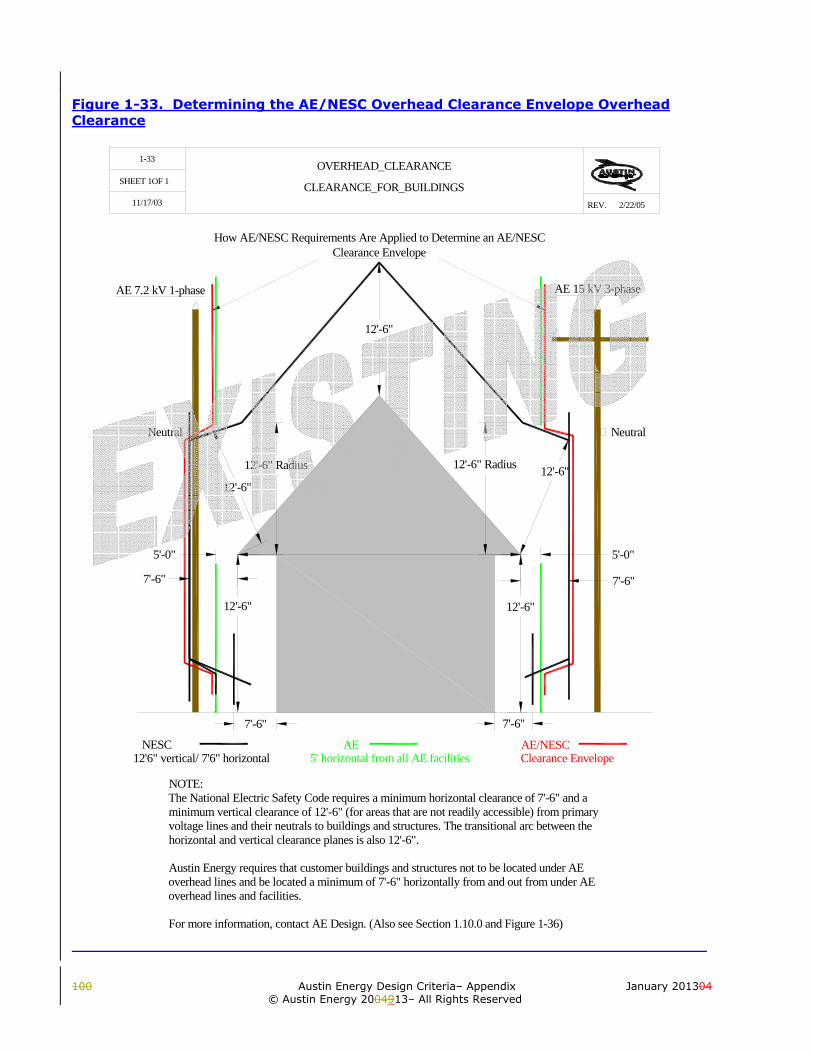
100 Austin Energy Design Criteria– Appendix January 201304
© Austin Energy 2004913– All Rights Reserved
Figure 1-33. Determining the AE/NESC Overhead Clearance Envelope Overhead Clearance
SHEET 1OF 1
REV.
1-33
11/17/03
OVERHEAD_CLEARANCE
CLEARANCE_FOR_BUILDINGS2/22/05
NeutralNeutral
Clearance Envelope
AE 15 kV 3-phaseAE 7.2 kV 1-phase
AE/NESCClearance Envelope
NOTE:The National Electric Safety Code requires a minimum horizontal clearance of 7'-6" and aminimum vertical clearance of 12'-6" (for areas that are not readily accessible) from primaryvoltage lines and their neutrals to buildings and structures. The transitional arc between thehorizontal and vertical clearance planes is also 12'-6".
Austin Energy requires that customer buildings and structures not to be located under AEoverhead lines and be located a minimum of 7'-6" horizontally from and out from under AEoverhead lines and facilities.
For more information, contact AE Design. (Also see Section 1.10.0 and Figure 1-36)
How AE/NESC Requirements Are Applied to Determine an AE/NESC
7'-6"
5'-0"
12'-6"
12'-6"
12'-6" Radius
12'-6"
7'-6"7'-6"
5'-0"
NESC AE
7'-6"
12'-6"12'-6" Radius
12'-6"
5' horizontal from all AE facilities12'6" vertical/ 7'6" horizontal

January 201309 Austin Energy Design Criteria – Appendix 51 © Austin Energy 20131009 – All Rights Reserved

100 Austin Energy Design Criteria– Appendix January 201304
© Austin Energy 2004913– All Rights Reserved
Figure 1-34. Overhead Clearance From Swimming Pools
SHEET OF
REV.
1-34
1 1
11/19/03 01/24/04

January 201309 Austin Energy Design Criteria – Appendix 53 © Austin Energy 20131009 – All Rights Reserved
REQUIREMENTOVERHEAD GUYS ORNEUTRAL
OPEN WIRE SECONDARYOR SERVICE
BUNDLED OR CABLEDSECONDARY OR SERVICE
A 22.5' 22.5' 25'
B 14.5' 14.5' 17'
C AS REQUIRED BY NESC SECTION 232
POLE LINE ORPRIMARY CONDUCTOR
25'
17'
CLEARANCE FROM SWIMMING POOL FOOT NOTES:
A- CLEARANCE IN ANY DIRECTION TO THE WATER LEVEL, EDGE OF WATER SURFACE, BASE OF DIVING PLATFORM, OR PERMANENTLY ANCHORED RAFT.B- CLEARANCE IN ANY DIRECTION TO THE OBSERVATION STAND, TOWER, OR DIVING PLATFORM.C. VERTICAL CLEARANCE OVER ADJACENT LAND.D. THIS LIMIT SHALL EXTEND TO THE OUTER EDGE OF THE STRUCTURES LISTED IN A AND B, BUT NOTLESS THAN 10 FT. OVERHEAD CONDUCTORS SHALL NOT BE PERMITTED TO PASS OVER POLES.
NOTE:THE ABOVE CLEARANCE BALUES ARE BASED UPON THE REQUIREMENTS OF THE NATIONAL ELECTRICALSAFETY CODE (SECTION 234) AND NATIONAL ELECTRICAL CODE (SECTION 680.8).
C
A
10' MIN.
C
10' MIN.
A
B
CONDUCTORS ARE PERMITTED IN SHADED AREAS (TYP.)
POOLRADIUSPOINT A
DD
D HORIZONTAL LIMIT CLEARANCE MEASURED FROM INSIDE POOL WALL OR OUTER EDGEOF THE DIVING BOARD OR PLATFORM.
SHEET OF
REV.
1-34
1 1
10/16/03 05/25/12

100 Austin Energy Design Criteria– Appendix January 201304
© Austin Energy 2004913– All Rights Reserved
Figure 1-35. Underground Clearance From Swimming Pools
5'
PROPERTY LINEUNDERGOUND ELECTRIC SUPPLY(RISER POLE, TRANSFORMER, PEDESTAL, ETC.)
10' MIN.
NOTE 3
NO
TE 1
NOTES:1. A SWIMMING POOL OR IT'S AUXILLIARY EQUIPMENT OR WATER PIPES SHALL NOT BE INSTALLED WITHIN 5' OF EXISTING BURIED CABLES OR CONDUIT FOR FUTURE A.E. FACILITIES.2. THE SERVICE SHALL BE INSTALLED IN A CONDUIT FROM THE ELECTRIC SUPPLY POINT TO THE METER.3. PADMOUNTED EQUIPMENT, PEDESTALS, PULL BOXES, ETC., SHALL BE LOCATED 10' OR MORE FROM THE WATERS EDGE.
POOL
LOCUS OF 5' MIN. RADIAL DISTANCEFROM THE WATER'S EDGE & POOLAUXILLIARY EQUIPMENT
AUXEQUIP
5'
APPROX. 3'
SERVICELATERAL
SHEET OF
REV.
1-35
1 1
10/16/03 05/25/12

January 201309 Austin Energy Design Criteria – Appendix 55 © Austin Energy 20131009 – All Rights Reserved
Figure 1-36. OSHA/Texas Safety Code Overhead Working Clearances
SHEET 1 OF 1
REV.
1-36
11/05/03
OSHA/TEXAS_SAFETY_CODE
OVERHEAD_WORKING_CLEARANCES
FROM_OVERHEAD_LINES_FOR_UNQUALIFIED_PERSONS 05/25/12
NOTE:The workers, scaffolding, and anythingin the workers hands must stay out of the appropriateworking clearance circles (10' radial clearance form any energized wire).
OSHA1910.333(c)(3)(i)(A/A1), 1910.333(c)(3)(i)(B)When an unqualified person is working in anelevated position near overhead lines (or on theground in the vicinity of overhead lines), the locationshall be such that the person and the longestconductive object he or she may contact cannot comecloser to any unguarded, energized overhead linethan....10ft.
Texas State Health & Safety Code 752.004.RESTRICTION ON ACTIVITIES NEAR LINES.(a) Unless a person, firm, corporation, or associationeffectively guards against danger by contact with theline as prescribed by Section 752.003, the person,firm, corporation, or association, either individuallyor through an agent or employee, may not perform afunction or activity on land, a building, a highway, orother premises if at any time it is possible that theperson performing the function or activity may: (1)move or be placed within six feet of a high voltageoverhead line while performing the function oractivity; or (2) bring any part of a tool, equipment,machine, or material within ten feet of a high voltageoverhead line while performing the function oractivity.
OSHA/Texas Safety Code Working Clearances From Overhead Lines For Unqualified Persons
12.5 kV
Secondary
R10'
R10'
12.5 kV
R6'
R10'
R6'
R10'

100 Austin Energy Design Criteria– Appendix January 201304
© Austin Energy 2004913– All Rights Reserved
Figure 1-37a & b. Residential Underground Service Lateral Responsibilities
4. POS AT METER PEDESTAL/METER AT METER PEDESTAL (OR METER RACK). (NOTES 4, 6, 7 & 9)
SERVICE CONDUCTORS INSTALLED BY A.E.
CUSTOMER INSTALLED CONDUIT
CUSTOMER INSTALLED CONDUIT& SERVICE CONDUCTORS POS
SERVICE CONDUCTORSINSPECTED BY EIS.
CONDUIT INSPECTED BYA.E. WORK MANAGEMENT
CUSTOMER INSTALLED CONDUIT& SERVICE CONDUCTORS
CONDUIT & SERVICE CONDUCTORSINSPECTED BY EIS.
POS/
3. POS AT P.B. OR PADMOUNT TRANSFORMER/METER AT BUILDING (NOTES 8 & 9)
2. APARTMENTS (5 METERS OR MORE)
1. POS AT BUILDING/METER AT BUILDING (NOTE 1)
CONDUIT INSPECTED BYA.E. WORK MANAGEMENT
TAPBOX
POS
SECONDARYRISER STUB
(NOTE 5)
SERVICE CONDUCTORS INSTALLED BY A.E.
CONDUIT INSPECTED BY A.E. (NOTE 2)
CUSTOMER INSTALLED CONDUITPOS
OR (NOTE 3)
PULLBOX
EXISTING PAD MOUNTTRANSFORMER
OR
(NOTE 3)
A.E. UTILITY POLE
EXISTING PAD MOUNTTRANSFORMER
PULLBOX
EXISTING PAD MOUNTTRANSFORMER
OR
(NOTE 3)
PULLBOX
EXISTING PAD MOUNTTRANSFORMER
OR
(NOTE 3)
SHEET OF
REV. 05/25/1210/16/03
11
1-37A

January 201309 Austin Energy Design Criteria – Appendix 57 © Austin Energy 20131009 – All Rights Reserved
KEY:POS- POINT OF SERVICE (POS LOCATION: FOR SINGLE-PHASE "SERVICE ONLY" SERVICE LATERALS TO 4 METERS OR LESS AND FOR INDIVIDUAL DWELLINGS OF 350 AMPERES OR LESS, CONTACT A.E. SPOTS & CONDUIT. FOR ALL OTHER POS LOCATIONS, CONTACT A.E. DESIGN. IMPORTANT: A.E. MAKES ALL ELECTRICAL CONNECTIONS BETWEEN THE CUSTOMER'S FACILITIES AND A.E. FACILITIES AT THE POS.)P.B.- PULL-BOX OR SERVICE-BOX.EIS- THE COA ELECTRIC INSPECTION SECTION AND ANY OTHER AUTHORIZED AND REQUIRED INSPECTION ENTITY.
NOTES:1. APPLIES TO THE UNDERGROUND RESIDENTIAL SERVICE LATERALS TO 4 METERS OR LESS AND FOR INDIVIDUAL DWELLINGS OF 350 AMPERES OR LESS SINGLE-PHASE.
2. FOR SINGLE-PHASE "SERVICE ONLY" SERVICE LATERALS TO 4 METERS OR LESS AND FOR INDIVIDUAL DWELLINGS OF 350 AMPERES OR LESS, CONTACT A.E. SPOTS & CONDUIT FOR CONDUIT INSPECTIONS. FOR ALL OTHER CONDUIT INSPECTIONS, CONTACT A.E. WORK MANAGEMENT.
3. FOR ATTACHMENT OF CUSTOMER INSTALLED CONDUIT TO A P.B. CONTAINING ENERGIZED A.E. CONDUCTORS AND FOR PULLING CUSTOMER INSTALLED SERVICE CONDUCTORS INTO A P.B. CONTAINING ENERGIZED A.E. CONDUCTORS OR INTO AN ENERGIZED A.E. PADMOUNTED TRANSFORMER OR OTHER ENERGIZED A.E. EQUIPMENT, CONTACT A.E. SPOTS & CONDUIT FOR NOTE 1 TYPE SERVICES AND A.E. DESIGN FOR ALL OTHERS.
4. FOR GROUPED, BANKED, OR MODULAR METERING, CONTACT A.E. ELECTRIC METER OPERATIONS SECTION.
5. FOR NEW SECONDARY RISER INSTALLATIONS, THE P.B., CONDUIT FROM THE P.B. TO THE RISER STUB, AND THE RISER STUB SHALL BE INSTALLED BY THE CUSTOMER AND INSPECTED BY A.E. WORK MANAGEMENT. A.E. WILL INSTALL THE SECONDARY RISER CONDUCTORS TO THE P.B.
6. CONTACT A.E. CT METER OPERATIONS FOR SINGLE-PHASE SERVICES OF 351 AMPERES OR MORE.
7. NORMALLY THE METER PEDESTAL IS INSTALLED WHEN THE CUSTOMER INSTALLS THE CONDUIT, P.B.'s AND TRANSFORMER PADS FOR THE A.E. URD PRIMARY CABLE, SECONDARY CABLE, AND PADMOUNTED TRANSFORMER INFRASTRUCTURE AND IS EXISTING AT THE TIME CUSTOMER INSTALLS HIS SERVICE LATERAL CONDUIT AND SERVICE CONDUCTORS. FOR NEW METER PEDESTALS, CONTACT A.E. DESIGN.
8. APPLIES TO SECONDARY RISER SERVICE AND SINGLE-PHASE SERVICE OF 351 AMPERES OR MORE.
9. FOR (NON-STANDARD) THREE-PHASE RESIDENTIAL SERVICE, SEE THE COMMERCIAL UNDERGROUND SERVICE LATERAL RESPONSIBILITIES DRAWING.
10. RESIDENTIAL SERVICE LATERAL INSPECTION REQUIREMENTS ARE DETERMINED BY THE RELATIVE LOCATIONS OF THE POINT OF SERVICE (POS) & A.E. METER. A. NORMAL POS LOCATIONS FOR RESIDENTIAL SERVICE ARE SPECIFIED IN THE A.E. DESIGN CRITERIA MANUAL & IN THE A.E. CRITERIA MANUAL EXHIBIT HANDBOOK. B. THE C.O.A. ELECTRIC INSPECTION (OR OTHER AUTHORIZED INSPECTION ENTITY) SETS THE REQUIREMENTS FOR AND INSPECTS ALL CUSTOMER INSTALLED AND OWNED SERVICE LATERAL CONDUCTORS ON THE LOAD SIDE OF THE POS. C. A.E. SETS THE REQUIREMENTS FOR (AND INSPECTS) ALL CUSTOMER INSTALLED SERVICE LATERAL CONDUITS INSTALLED AHEAD OF THE A.E. METER.
SHEET OF
REV.
1-37B
1 1
10/16/03 05/25/12

100 Austin Energy Design Criteria– Appendix January 201304
© Austin Energy 2004913– All Rights Reserved
Figure 1-38a & b. Commercial Underground Service Lateral Responsibilities Underground Service Lateral Responsibilities
3. POS AT P.B. OR TRANSFORMER/MULTIPLE METERS AT BUILDING
CUSTOMER INSTALLED CONDUIT,TAP-BOX & SERVICE CONDUCTOR
SERVICE CONDUCTOR& TAP-BOX INSPECTED BY EIS
TAPBOX
CONDUIT INSPECTED BYA.E. WORK MANAGEMENT
2. POS AT P.B. OR TRANSFORMER/METER(S) AT METER RACK
1. POS (POINT OF SERVICE) AT P.B. OR TRANSFORMER/METER AT BUILDING
CONDUIT INSPECTION(SEE NOTE 6.D)
SERVICE CONDUCTORSINSPECTED BY EIS.
CUSTOMER INSTALLED CONDUIT& SERVICE CONDUCTORS
CONDUIT & SERVICE CONDUCTORSINSPECTED BY EIS.
METER RACK.CT's IN TRANSFORMER
SECONDARY COMPARTMENT.(NOTES 2&4)
CUSTOMER INSTALLED CONDUIT& SERVICE CONDUCTORS POS
SECONDARYRISER STUB
(NOTE 3)
POS
PULLBOX
PADMOUNT TRANSFORMER
OR
(NOTES 1,3 & 5)
EXISTING PADMOUNTTRANSFORMER
PULLBOX
POSOR
(NOTES1,4,& 5)
A.E. UTILITY POLE
EXISTING PADMOUNTTRANSFORMER
OR(NOTES1,3,& 5)
SHEET OF
REV. 05/25/1210/16/03
11
1-38A

January 201309 Austin Energy Design Criteria – Appendix 59 © Austin Energy 20131009 – All Rights Reserved
NOTES:1. FOR ATTACHMENT OF CUSTOMER INSTALLED CONDUIT TO A P.B. CONTAINING ENERGIZED A.E. CONDUCTORS AND FOR PULLING CUSTOMER INSTALLED SERVICE CONDUCTORS INTO A P.B. CONTAINING ENERGIZED A.E. CONDUCTORS OR INTO AN ENERGIZED A.E. PADMOUNTED TRANSFORMER OR OTHER ENERGIZED A.E. EQUIPMENT, CONTACT A.E. SPOTS & CONDUIT FOR SERVICES OF FOUR METERS OR LESS OF THE SINGLE PHASE 120/240 VOLT ELECTRIC SERVICE (350 AMPERES OR LESS) OR 2-3 PHASE ELECTRIC SERVICE (225 AMPERES OR LESS OF COMBINED MAIN DISCONNECT COMPASSITY AS DETERMINED BY THE MANUFACUTER'S EQUIPMENT RATING) AND A.E. DESIGN FOR ALL OTHERS.
2. FOR GROUPED, BANKED, OR MODULAR METERING, CONTACT A.E. ELECTRIC METER OPERATIONS SECTION.
3. FOR NEW SECONDARY RISER INSTALLATIONS, THE P.B., CONDUIT FROM THE P.B. TO THE RISER STUB, AND THE RISER STUB SHALL BE INSTALLED BY THE CUSTOMER AND INSPECTED BY A.E. WORK MANAGEMENT. A.E. WILL INSTALL THE SECONDARY RISER CONDUCTORS TO THE P.B.
4. CONTACT A.E. CT METER OPERATIONS FOR SINGLE-PHASE SERVICES OF 351 AMPERES OR MORE OR 3 PHASE SERVICES OF 226 AMPERES OR MORE OR ANY CT METERED SERVICE.
5. ASSUMES THAT THE CIVIL WORK INFRASTRUCTURE OF CONDUIT, P.B.'S, & TRANSFORMER PADS FOR THE A.E. PRIMARY CABLE, SECONDARY CABLE, AND PADMOUNTED TRANSFORMER(S) HAVE BEEN INSTALLED BY THE CUSTOMER AND ARE EXISTING AT THE TIME CUSTOMER INSTALLS THE SERVICE LATERAL CONDUIT AND SERVICE CONDUCTORS. FOR NEW INFRASTRUCTURE REQUIREMENTS, CONTACT A.E. DESIGN.
6. COMMERCIAL SERVICE LATERAL CONDUIT INSPECTION REQUIREMENTS ARE DETERMINED BY THE RELATIVE LOCATIONS OF THE POINT OF SERVICE (POS) AND THE A.E. METER. A. THE CUSTOMER INSTALLS AND OWNS ALL COMMERCIAL SERVICE LATERAL CONDUCTORS. THESE CONDUCTORS MUST BE INSPECTED BY THE C.O.A. ELECTRIC INSPECTION SECTION (OR OTHER AUTHORIZED INSPECTIONS ENTITIY). B. THE POINT OF SERVICE IS AT THE PULLBOX (P.B.) OR THE SECONDARY TERMINAL OF THE TRANSFORMER. C. WHEN THE METER IS INSTALLLED ON THE BUILDING OR STRUCTURE BEING SERVED, A.E. SETS THE REQUIREMENTS FOR AND INSPECTS ALL CUSTOMER INSTALLED SERVICE LATERAL CONDUITS INSTALLED AHEAD OF THE A.E. METER. D. FOR CONDUIT INSPECTION, CONTACT A.E. SPOTS & CONDUIT FOR SERVICES OF FOUR METERS OR LESS OF SINGLE PHASE 120/240 VOLT ELECTRIC SERVICE (350 AMPERES OR LESS) OR TO THREE PHASE ELECTRIC SERVICE (225 AMPERES OR LESS OF COMBINED MAIN DISCONNECT CAPACITY AS DETERMINED BY THE MANUFACTURER'S EQUIPMENT RATING) AND A.E. WORK MANAGEMENT FOR ALL OTHERS.
KEY:POS- POINT OF SERVICE (POS LOCATION: FOR COMMERCIAL CUSTOMERS, THE POS IS USUALLY THE P.B. OR THE SECONDARY COMPARTMENT OF THE PADMOUNTED TRANSFORMER. IMPORTANT. A.E. CREWS MAKE ALL ELECTRICAL CONNECTIONS BETWEEN THE CUSTOMER'S FACILITIES AND A.E. FACILITIES AT THE POS.) IF THERE ARE ANY QUESTIONS, CONTACT A.E. DESIGN.
P.B.- PULL-BOX OR SERVICE-BOX.
EIS- THE COA ELECTRIC INSPECTION SECTION AND ANY OTHER AUTHORIZED AND REQUIRED INSPECTION ENTITY.
SHEET OF
REV. 05/25/1210/16/03
11
1-38B
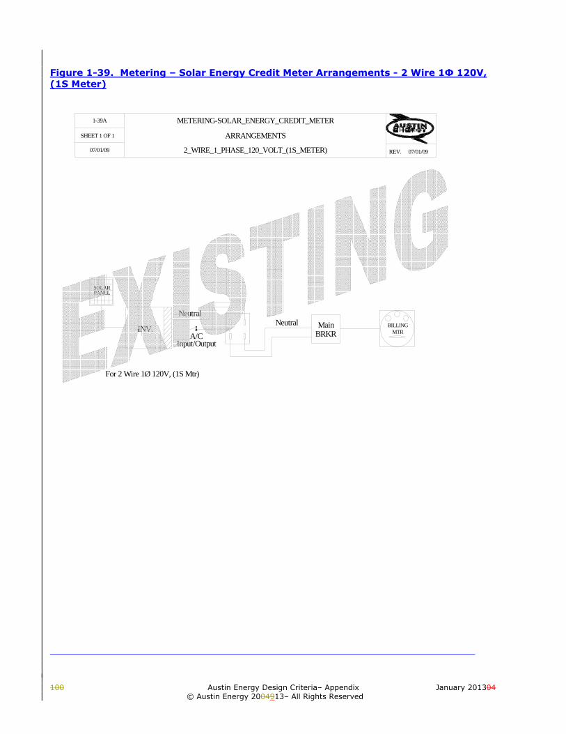
100 Austin Energy Design Criteria– Appendix January 201304
© Austin Energy 2004913– All Rights Reserved
Figure 1-39. Metering – Solar Energy Credit Meter Arrangements - 2 Wire 1Φ 120V, (1S Meter)
INV.
Neutral
For 2 Wire 1Ø 120V, (1S Mtr)
Neutral MainBRKR
BILLINGMTRA/C
Input/Output
SOLARPANEL
SHEET 1 OF 1
REV.
1-39A
07/01/09
METERING-SOLAR_ENERGY_CREDIT_METER
ARRANGEMENTS
2_WIRE_1_PHASE_120_VOLT_(1S_METER) 07/01/09

January 201309 Austin Energy Design Criteria – Appendix 61 © Austin Energy 20131009 – All Rights Reserved

100 Austin Energy Design Criteria– Appendix January 201304
© Austin Energy 2004913– All Rights Reserved
INV.
Neutral
For 2 Wire 1Ø 120V, (1S Mtr)
Neutral MainBRKR
BILLINGMTRA/C
Input/Output
SOLARPANEL
SHEET 1 OF 1
REV.
1-39
07/01/09
METERING-SOLAR_ENERGY_CREDIT_METER
ARRANGEMENTS
2_WIRE_1_PHASE_120_VOLT_(1S_METER) 05/25/12

January 201309 Austin Energy Design Criteria – Appendix 63 © Austin Energy 20131009 – All Rights Reserved

100 Austin Energy Design Criteria– Appendix January 201304
© Austin Energy 2004913– All Rights Reserved
Figure 1-40. Metering – Solar Energy Credit Meter Arrangements - 2 Wire 1Φ 120V, (12S Meter)
INV.BILLING
MTRMain
BRKR
SOLARPANEL
BATTBANK
CRITICALLOAD
A/C Input
A/C Output
Neutral
For 2 Wire 1Ø 120V, (12S Mtr)
SHEET 1 OF 1
REV.
1-40
07/01/09
METERING-SOLAR_ENERGY_CREDIT_METER
ARRANGEMENTS
2_WIRE_1_PHASE_120_VOLT_(1S_METER) 07/01/09

January 201309 Austin Energy Design Criteria – Appendix 65 © Austin Energy 20131009 – All Rights Reserved
Figure 1-41. Metering – Solar Energy Credit Meter Arrangements - 3 Wire 1Φ 120/240V, (2S Meter) or 3 Wire 3Φ 120/208V, (12S Meter)
BATTBANK
SOLARPANEL
INV.Main
BRKRBILLING
MTR
CRITICALLOAD
NeutralAC InAC In
NeutralAC OutAC Out
orFor 3 Wire 3Ø, 120/208V (12S Mtr)
For 3 Wire 1Ø, 120/240V (2S Mtr)
SHEET 1 OF 1
REV.
1-41
07/01/09
METERING-SOLAR_ENERGY_CREDIT_METERARRANGEMENTS
3_WIRE_1_PHASE_120/240V_(2S_METER)_OR
07/01/093_WIRE_1_PHASE_120/208V_(12S_METER)

100 Austin Energy Design Criteria– Appendix January 201304
© Austin Energy 2004913– All Rights Reserved
Figure 1-42. Metering – Solar Energy Credit Meter Arrangements - 4 Wire 3Φ 120/208V, (16S Meter) or 4 Wire 3Φ 277/480V, (16S Meter)
INV.
BATTBANK
SOLARPANEL
MainBRKR
BILLINGMTR
CRITICALLOAD
Neutral
AC InAC In
Neutral
AC Out
AC In
AC OutAC Out
*Only Used withBattery BackUp
orFor 4 Wire 3Ø, 277/480V (16S Mtr)
For 4 Wire 3Ø, 120/208V (16S Mtr)
SHEET 1 OF 1
REV.
1-42
07/01/09
METERING-SOLAR_ENERGY_CREDIT_METERARRANGEMENTS
4_WIRE_3_PHASE_120/208V_(16S_METER)_OR
07/01/094_WIRE_3_PHASE_277/480V_(16S_METER)

January 201309 Austin Energy Design Criteria – Appendix 67 © Austin Energy 20131009 – All Rights Reserved