Aussie Hydraulic Drive Blaster - Aussie Pumps manufacturer of
16
OPERATOR’S INSTRUCTION MANUAL Operators must read this manual and understand it before operang this machine Sept 2018 Models: WHY1520 HYD, THY2715 HYD, TTL 1330 HYD, TTL 2028 HYD TTK 2130 HYD, RAL 2035 HYD REF: APHYDHPBVER3 Aussie Eco-Clean Hydraulic Drive High Pressure Blaster Hydraulic drive blasters to 500 BAR (7,200 psi) coming soon Australian Pump Industries www.aussiepumps.com.au Hydraulic specialist to install Note: Max pump rpm 1450
Transcript of Aussie Hydraulic Drive Blaster - Aussie Pumps manufacturer of
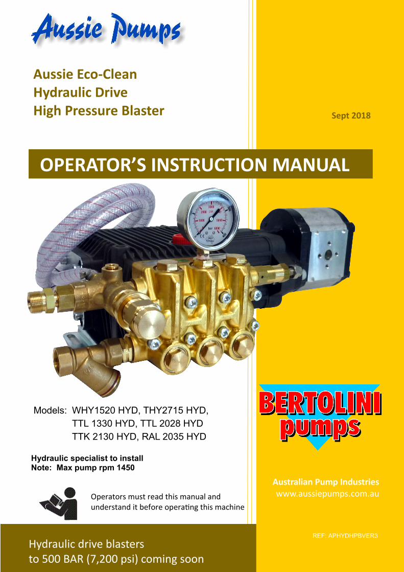
OPERATOR’S INSTRUCTION MANUAL
Operators must read this manual and understand it before operating this machine
Sept 2018
Models: WHY1520 HYD, THY2715 HYD,
TTL 1330 HYD, TTL 2028 HYD
TTK 2130 HYD, RAL 2035 HYD
REF: APHYDHPBVER3
Aussie Eco-Clean Hydraulic Drive High Pressure Blaster
Hydraulic drive blasters to 500 BAR (7,200 psi) coming soon
Australian Pump Industries www.aussiepumps.com.au
Hydraulic specialist to install Note: Max pump rpm 1450
Aussie Hydraulic Drive Blaster … Operation & Maintenance Manual 2
Sept 2018
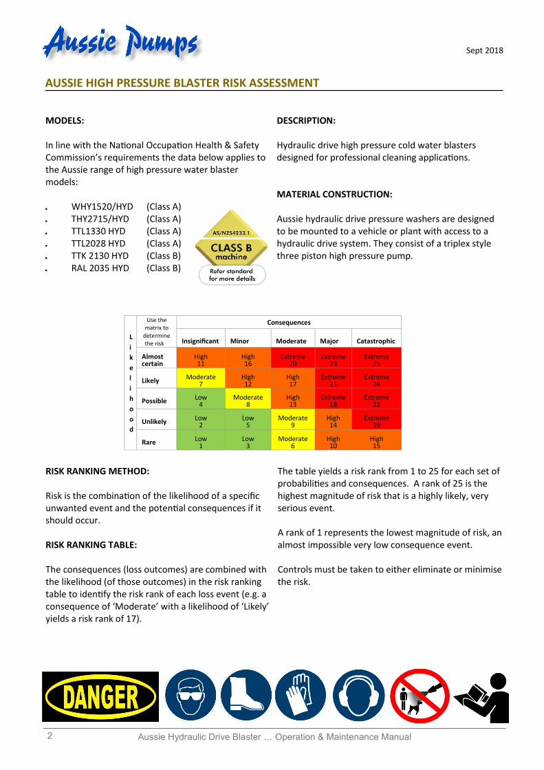
MODELS: In line with the National Occupation Health & Safety Commission’s requirements the data below applies to the Aussie range of high pressure water blaster models: WHY1520/HYD (Class A) THY2715/HYD (Class A) TTL1330 HYD (Class A) TTL2028 HYD (Class A) TTK 2130 HYD (Class B) RAL 2035 HYD (Class B)
DESCRIPTION: Hydraulic drive high pressure cold water blasters designed for professional cleaning applications. MATERIAL CONSTRUCTION: Aussie hydraulic drive pressure washers are designed to be mounted to a vehicle or plant with access to a hydraulic drive system. They consist of a triplex style three piston high pressure pump.
AUSSIE HIGH PRESSURE BLASTER RISK ASSESSMENT
RISK RANKING METHOD: Risk is the combination of the likelihood of a specific unwanted event and the potential consequences if it should occur. RISK RANKING TABLE: The consequences (loss outcomes) are combined with the likelihood (of those outcomes) in the risk ranking table to identify the risk rank of each loss event (e.g. a consequence of ‘Moderate’ with a likelihood of ‘Likely’ yields a risk rank of 17).
The table yields a risk rank from 1 to 25 for each set of probabilities and consequences. A rank of 25 is the highest magnitude of risk that is a highly likely, very serious event. A rank of 1 represents the lowest magnitude of risk, an almost impossible very low consequence event. Controls must be taken to either eliminate or minimise the risk.
L
i
k
e
l
i
h
o
o
d
Consequences Use the matrix to
determine the risk Insignificant Minor Moderate Major Catastrophic
Almost certain
High 11
High 16
Extreme 20
Extreme 23
Extreme 25
Likely Moderate 7
High 12
High 17
Extreme 21
Extreme 24
Possible Low 4
Moderate 8
High 13
Extreme 18
Extreme 22
Unlikely Low 2
Low 5
Moderate 9
High 14
Extreme 19
Rare Low 1
Low 3
Moderate 6
High 10
High 15
Aussie Hydraulic Drive Blaster … Operation & Maintenance Manual 3
Sept 2018
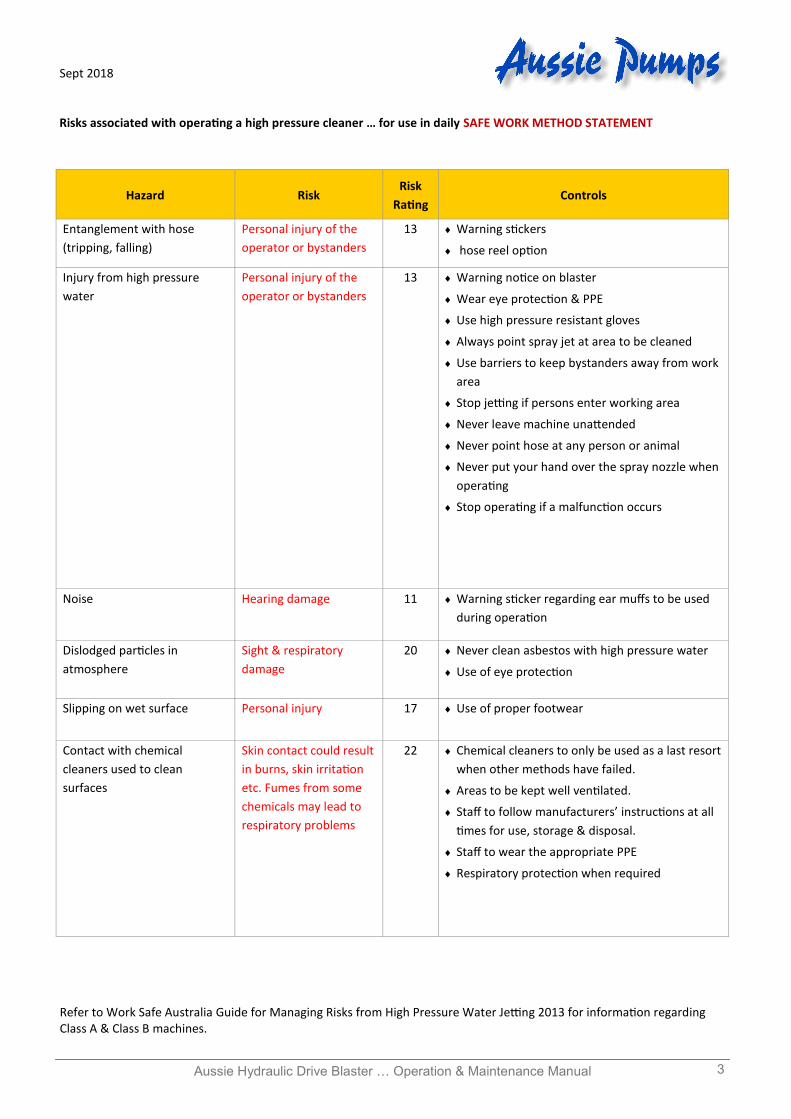
Hazard Risk Risk
Rating Controls
Entanglement with hose
(tripping, falling)
Personal injury of the
operator or bystanders
13 Warning stickers
hose reel option
Injury from high pressure
water
Personal injury of the
operator or bystanders
13 Warning notice on blaster
Wear eye protection & PPE
Use high pressure resistant gloves
Always point spray jet at area to be cleaned
Use barriers to keep bystanders away from work
area
Stop jetting if persons enter working area
Never leave machine unattended
Never point hose at any person or animal
Never put your hand over the spray nozzle when
operating
Stop operating if a malfunction occurs
Noise Hearing damage 11 Warning sticker regarding ear muffs to be used
during operation
Dislodged particles in
atmosphere
Sight & respiratory
damage
20 Never clean asbestos with high pressure water
Use of eye protection
Slipping on wet surface Personal injury 17 Use of proper footwear
Contact with chemical
cleaners used to clean
surfaces
Skin contact could result
in burns, skin irritation
etc. Fumes from some
chemicals may lead to
respiratory problems
22 Chemical cleaners to only be used as a last resort
when other methods have failed.
Areas to be kept well ventilated.
Staff to follow manufacturers’ instructions at all
times for use, storage & disposal.
Staff to wear the appropriate PPE
Respiratory protection when required
Refer to Work Safe Australia Guide for Managing Risks from High Pressure Water Jetting 2013 for information regarding Class A & Class B machines.
Risks associated with operating a high pressure cleaner … for use in daily SAFE WORK METHOD STATEMENT
Aussie Hydraulic Drive Blaster … Operation & Maintenance Manual 4
Sept 2018
CONTENTS
Risk Assessment ............................................................................................................................. 2
System Specifications .................................................................................................................... 4
Guarantee ...................................................................................................................................... 5
Standard Equipment ...................................................................................................................... 5
Installation of Hydraulic Motor ..................................................................................................... 5
Initial Set Up of Hydraulic Blaster .................................................................................................. 6
Safety Precautions ......................................................................................................................... 7
Assembly & Preparation for Use ................................................................................................... 8
High Pressure Hose ............................................................................................................... 8
Water Supply Hose ............................................................................................................... 9
Operation ...................................................................................................................................... 10
Accessories .................................................................................................................................... 10
Care & Maintenance ..................................................................................................................... 11
ASP System ................................................................................................................................... 11
Trouble Shooting Guide ................................................................................................................ 12
Parts Identification ........................................................................................................................ 13
Pump Breakdowns ........................................................................................................................ 14
Maintenance Checklists ................................................................................................................ 16
* * W A R N I N G * * AUSSIE HEAVY DUTY WATER BLASTERS ARE DESIGNED FOR PROFESSIONAL OPERATORS ONLY
Before attempting to operate your machine please read this Instruction Manual thoroughly following all directions carefully. By doing so you will ensure safe operation of the unit and will enjoy long and trouble free service from your heavy duty water blaster.
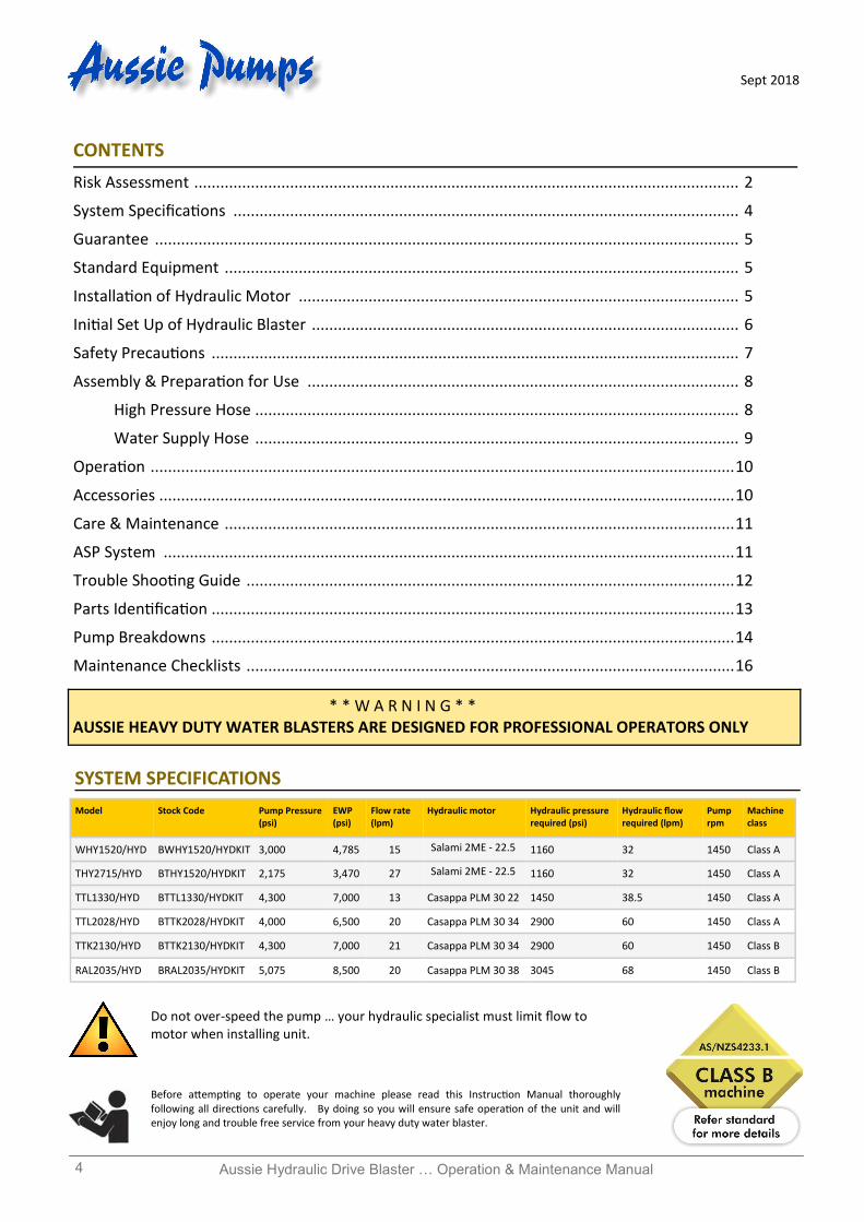
Model Stock Code Pump Pressure (psi)
EWP (psi)
Flow rate (lpm)
Hydraulic motor Hydraulic pressure required (psi)
Machine class
Hydraulic flow required (lpm)
Pump rpm
WHY1520/HYD BWHY1520/HYDKIT 3,000 4,785 15 Salami 2ME - 22.5 1160 32 1450 Class A
THY2715/HYD BTHY1520/HYDKIT 2,175 3,470 27 Salami 2ME - 22.5 1160 32 1450 Class A
TTL1330/HYD BTTL1330/HYDKIT 4,300 7,000 13 Casappa PLM 30 22 1450 Class A 38.5 1450
TTL2028/HYD BTTK2028/HYDKIT 4,000 6,500 20 Casappa PLM 30 34 2900 Class A 60 1450
TTK2130/HYD BTTK2130/HYDKIT 4,300 7,000 21 Casappa PLM 30 34 2900 Class B 60 1450
RAL2035/HYD BRAL2035/HYDKIT 5,075 8,500 20 Casappa PLM 30 38 3045 68 1450 Class B
SYSTEM SPECIFICATIONS
Do not over-speed the pump … your hydraulic specialist must limit flow to motor when installing unit.
Aussie Hydraulic Drive Blaster … Operation & Maintenance Manual 5
Sept 2018
GUARANTEE This Aussie Eco Clean product is guaranteed against
faults in manufacture for one year from purchase. The
Bertolini pump has a four year warranty, but must be
serviced by an authorised service agent every six
months to maintain this warranty. Keep your receipt
as proof of purchase and all service receipts. This
guarantee is invalid if the product is found to have
been abused in any way, or not used for the purpose
for which it was intended.
Routine maintenance is the owner’s responsibility.
Failure to maintain the machine in line with the
services outlined on the back page will invalidate
warranty. High pressure accessories carry a 3 month
warranty.
Where possible return faulty goods to the place of
purchase. No products can be returned to us without
our prior permission. The reason for return must be
clearly state.
N.B. Warranty is not transferrable to third parties
in the event of sale of the machine within the
warranty period. Please note that any parts
used in warranty repairs are guaranteed for a
period limited by the original warranty of the
parent product.
Our goods come with guarantees that cannot be
excluded under the Australian Consumer Law. You are
entitled to a replacement or refund for a major failure
and for compensation for any other reasonably
foreseeable loss or damage. You are also entitled to
have the goods repaired or replaced if the goods fail
to be of acceptable quality and the failure does not
amount to a major failure.
The benefits under the Aussie Pump warranty are in
addition to other rights under Australian Consumer
Law.
Hydraulic drive warranty is the responsibility of the
hydraulic drive unit manufacturer. The unit must be
returned to authorised dealer for evaluation of
warranty.
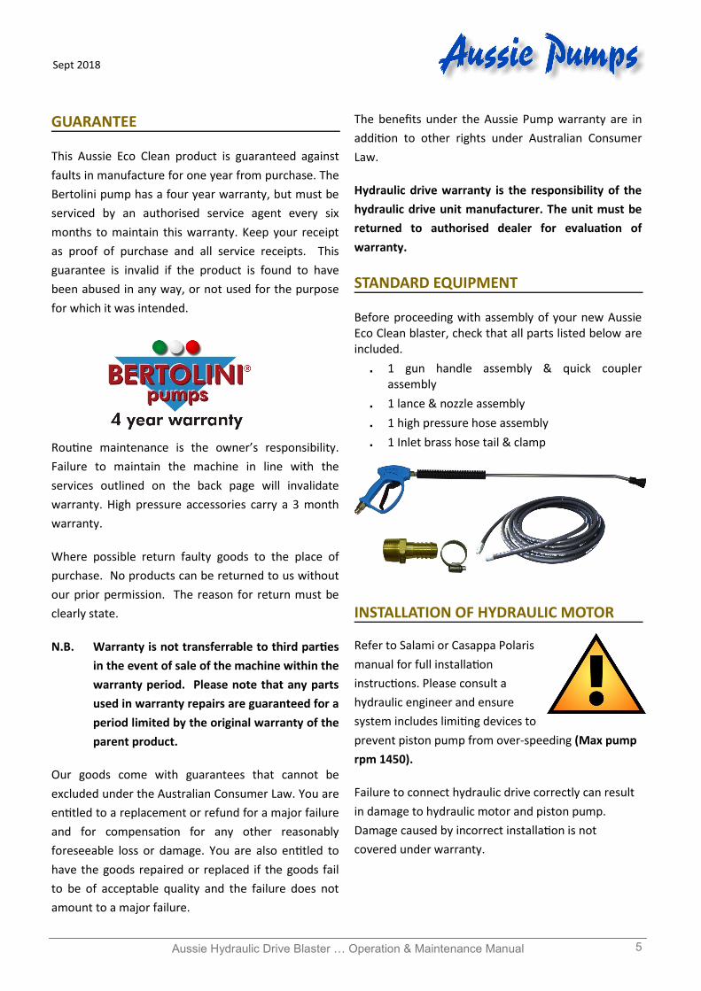
STANDARD EQUIPMENT Before proceeding with assembly of your new Aussie Eco Clean blaster, check that all parts listed below are included.
1 gun handle assembly & quick coupler assembly
1 lance & nozzle assembly
1 high pressure hose assembly
1 Inlet brass hose tail & clamp
INSTALLATION OF HYDRAULIC MOTOR
Refer to Salami or Casappa Polaris
manual for full installation
instructions. Please consult a
hydraulic engineer and ensure
system includes limiting devices to
prevent piston pump from over-speeding (Max pump
rpm 1450).
Failure to connect hydraulic drive correctly can result
in damage to hydraulic motor and piston pump.
Damage caused by incorrect installation is not
covered under warranty.
Aussie Hydraulic Drive Blaster … Operation & Maintenance Manual 6
Sept 2018
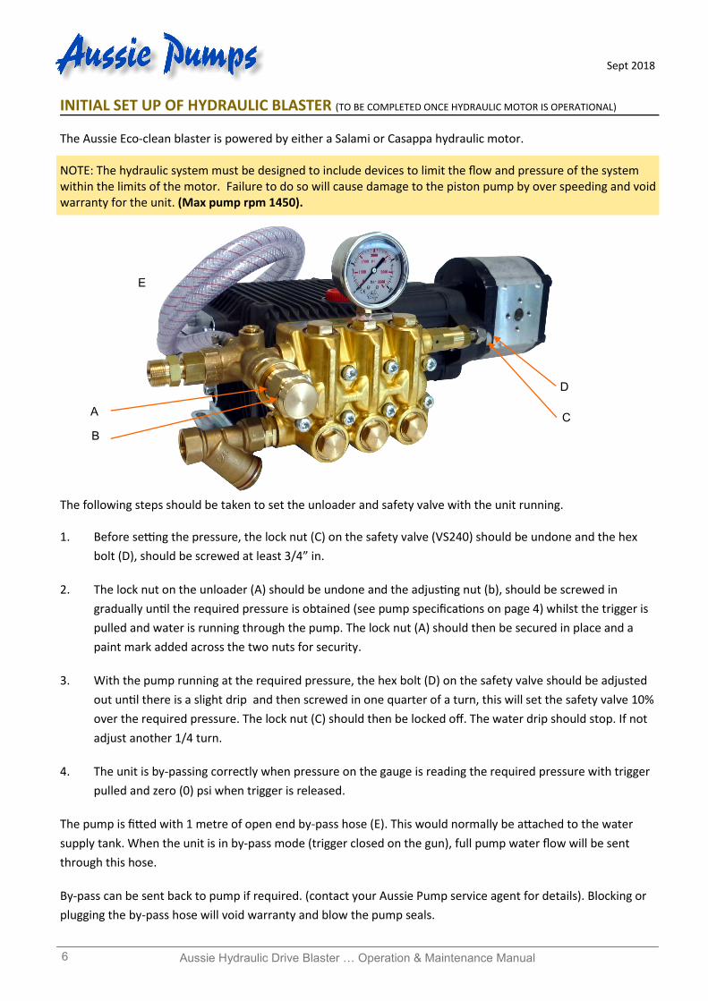
INITIAL SET UP OF HYDRAULIC BLASTER (TO BE COMPLETED ONCE HYDRAULIC MOTOR IS OPERATIONAL)
The Aussie Eco-clean blaster is powered by either a Salami or Casappa hydraulic motor. NOTE: The hydraulic system must be designed to include devices to limit the flow and pressure of the system within the limits of the motor. Failure to do so will cause damage to the piston pump by over speeding and void warranty for the unit. (Max pump rpm 1450).
The following steps should be taken to set the unloader and safety valve with the unit running. 1. Before setting the pressure, the lock nut (C) on the safety valve (VS240) should be undone and the hex
bolt (D), should be screwed at least 3/4” in.
2. The lock nut on the unloader (A) should be undone and the adjusting nut (b), should be screwed in
gradually until the required pressure is obtained (see pump specifications on page 4) whilst the trigger is
pulled and water is running through the pump. The lock nut (A) should then be secured in place and a
paint mark added across the two nuts for security.
3. With the pump running at the required pressure, the hex bolt (D) on the safety valve should be adjusted
out until there is a slight drip and then screwed in one quarter of a turn, this will set the safety valve 10%
over the required pressure. The lock nut (C) should then be locked off. The water drip should stop. If not
adjust another 1/4 turn.
4. The unit is by-passing correctly when pressure on the gauge is reading the required pressure with trigger
pulled and zero (0) psi when trigger is released.
The pump is fitted with 1 metre of open end by-pass hose (E). This would normally be attached to the water
supply tank. When the unit is in by-pass mode (trigger closed on the gun), full pump water flow will be sent
through this hose.
By-pass can be sent back to pump if required. (contact your Aussie Pump service agent for details). Blocking or
plugging the by-pass hose will void warranty and blow the pump seals.
A
B
C
D
E
Aussie Hydraulic Drive Blaster … Operation & Maintenance Manual 7
Sept 2018
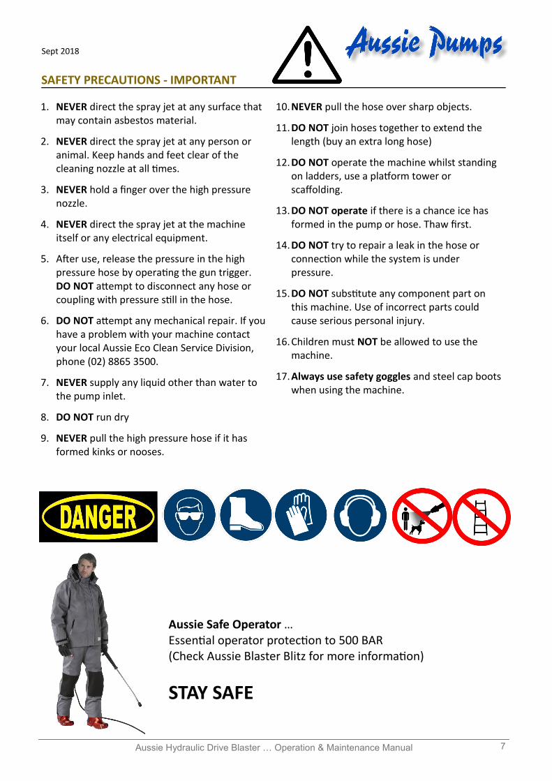
Aussie Safe Operator … Essential operator protection to 500 BAR (Check Aussie Blaster Blitz for more information)
STAY SAFE
1. NEVER direct the spray jet at any surface that may contain asbestos material.
2. NEVER direct the spray jet at any person or animal. Keep hands and feet clear of the cleaning nozzle at all times.
3. NEVER hold a finger over the high pressure nozzle.
4. NEVER direct the spray jet at the machine itself or any electrical equipment.
5. After use, release the pressure in the high pressure hose by operating the gun trigger. DO NOT attempt to disconnect any hose or coupling with pressure still in the hose.
6. DO NOT attempt any mechanical repair. If you have a problem with your machine contact your local Aussie Eco Clean Service Division, phone (02) 8865 3500.
7. NEVER supply any liquid other than water to the pump inlet.
8. DO NOT run dry
9. NEVER pull the high pressure hose if it has formed kinks or nooses.
10. NEVER pull the hose over sharp objects.
11. DO NOT join hoses together to extend the length (buy an extra long hose)
12. DO NOT operate the machine whilst standing on ladders, use a platform tower or scaffolding.
13. DO NOT operate if there is a chance ice has formed in the pump or hose. Thaw first.
14. DO NOT try to repair a leak in the hose or connection while the system is under pressure.
15. DO NOT substitute any component part on this machine. Use of incorrect parts could cause serious personal injury.
16. Children must NOT be allowed to use the machine.
17. Always use safety goggles and steel cap boots when using the machine.
SAFETY PRECAUTIONS - IMPORTANT
Aussie Hydraulic Drive Blaster … Operation & Maintenance Manual 8
Sept 2018
High pressure hose connection
Supply hose (insert brass hose tail first)
ASSEMBLY & PREPARATION FOR USE
If pressure drops off, check nozzle for
wear. Nozzles should be replaced on
a regular basis (every month for
machines in regular use, every 3
months for machines used
intermittently. Using the machine
with the incorrect nozzle size or worn
nozzle will void warranty and can be
dangerous to the operator.
1. Check the oil in the pump. With the machine on
a level surface the oil level should cover the red
dot in the oil level sight glass on the side of the
machine. If necessary, top up with SAE 30w 50
oil (non foaming type). Do not mix different
grades of oil as this may affect the machines
performance. If alternative oil is used, first
empty out oil by unscrewing drain plug in
bottom of machine.
2. Ensure breather plug is fitted to pump (red/
black)
WARNING: Before operation ensure top
mounted oil filler plug is replaced by breather.
Failure to fit breather and keep clean can result
in over pressuring of oil chamber (crank case)
and can blow oil seals. This will void warranty.
3. Check hydraulic fluid level. Refer to hydraulic
drive hand book.
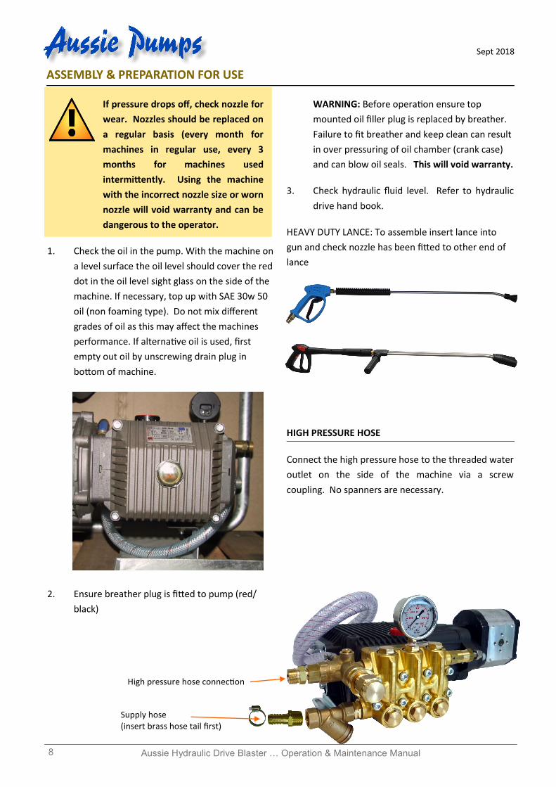
HEAVY DUTY LANCE: To assemble insert lance into
gun and check nozzle has been fitted to other end of
lance
HIGH PRESSURE HOSE
Connect the high pressure hose to the threaded water
outlet on the side of the machine via a screw
coupling. No spanners are necessary.
Aussie Hydraulic Drive Blaster … Operation & Maintenance Manual 9
Sept 2018
WATER SUPPLY HOSE:
Use a good quality supply hose (not supplied) of 19mm
diameter minimum on TTL & TTK versions, 25mm on
RAL version.
Fasten the one end of the hose to the inlet hose
connector securing using a worm drive clamp. This
connection MUST be tight to avoid leaks. (19mm hose
tail provided TTL & TTK versions, 25mm hose tail on
RAL version. )
Water supply can be by means of either:
$ Mains Supply
Secure the free end of the hose to your tap using a
suitable tap adaptor (not supplied - available
through all good hardware and garden supply
stores).
$ Syphon Fed Supply
Place the free end of the hose into a water tank or
container and the pump will draw water itself.
Use a larger diameter suction hose, at least 3/4"
diameter and no more than 2 metres long. Water
supply must be above or level with pump.
NOTE: The unit is fitted with a Y strainer inlet filter.
Ensure this is removed and rinsed to clear debris
before each use.
OPERATION:
Turn on water supply if applicable. Note: Tap
should be full on.
Pull the trigger to expel air from the system.
Water will trickle from the end of the lance
when air is expelled.
Engage hydraulic to power to blaster.
Check that there are no leaks in the line
connections, gun or power lance. Pressure
begins when the pistol trigger is squeezed.
SHUT DOWN
Turn off water supply if applicable.
Disengage hydraulic to power to blaster.
Pull the trigger release pressure from the
system. Gun trigger should be locked to prevent
accidental activation.
Hose and gun/lance assembly can now be
stowed or detached.
NOTE: Failure to release pressure before
disconnecting the hose quick coupler will result in the
quick coupler o-ring seal blowing out. This o-ring
must be replaced before operating machine.
ACCESSORIES: (CONSULT AUSSIE BLASTER BLITZ FOR DETAILS)
Your Aussie water blaster can be used with a wide
variety of optional extras to enhance performance.
To use the accessories you must first disassemble the
lance. Unscrew quick coupler to unlock the lance.
The accessories can then be connected to the end of
the lance assembly. If quick coupler is not supplied it
can be purchased from your local Aussie Eco-Clean
Distributor.
TURBO LANCE - A correctly selected heavy
duty turbo lance can cut pressure cleaning time
in half and is a very important accessory.
SANDBLAST HEAD - Wet grit-blasting is safe
and tremendously effective. Ideal for rust
removal, paint stripping and graffiti removal.
OPTIONAL LANCES - A range of optional lances
in stainless steel or zinc plated steel are
available in lengths of up to 2 metres.
ROTARY CLEANER - The Aussie Eco-Clean rotary
cleaner allows flat surfaces to be cleaned in a
fraction of the time normally taken. Ideal for
contractors and professional users.
Aussie Hydraulic Drive Blaster … Operation & Maintenance Manual 10
Sept 2018
LONG LENGTH HOSES - HOSE REELS,
COUPLINGS - A wide range of optional long
length hose assemblies, rapid reel hose reels
and quick couplers and fittings are available to
enhance your machine=s performance.
Consult your Aussie Eco-Clean Distributor for
details.
CARE AND MAINTENANCE:
AFTER EACH USE..... If cleaning agents have been mixed with the incoming water, it is particularly important to flush the machine with clean water after use. If there is a danger of freezing anti-freeze should be mixed with the flush water or the machine must be completely drained. After the final flush stop the machine. DO NOT allow the machine to idle for more than 15 seconds. This is particularly important when there is a danger of freezing. Do not run for longer without water supply.
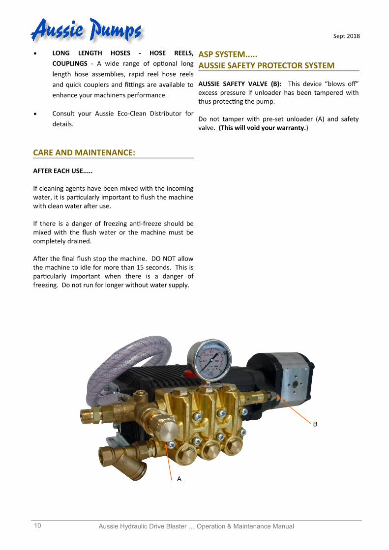
ASP SYSTEM..... AUSSIE SAFETY PROTECTOR SYSTEM
AUSSIE SAFETY VALVE (B): This device “blows off” excess pressure if unloader has been tampered with thus protecting the pump. Do not tamper with pre-set unloader (A) and safety valve. (This will void your warranty.)
B
A
Aussie Hydraulic Drive Blaster … Operation & Maintenance Manual 11
Sept 2018
FAULT
CAUSE
REMEDY
Pump running normally but pressure low on installation
Pump sucking air Valves sticking Unloader valve seat faulty Nozzle incorrectly sized Worn piston packing
Check water supply and possibility of air ingress. Check and clean or replace if necessary Check and replace Check and replace Check and replace
Fluctuating Pressure
Valves worn Valves blocked Pump sucking air Worn piston packing
Check and replace Check and replace Check water supply and air ingress at joints in suction line Check and replace
Pressure low after period of normal use
Nozzle worn Check valves worn Check valves blocked Unloader valve seat worn Worn piston packing Cracked pistons from dry running
Check and replace Check and replace Check and clean Check and replace Check and replace Replace pistons
Pump Noisy
Air in suction Broken or weak suction or delivery valve spring Foreign matter in valves Worn bearing Excessive temperature of liquid
Check water supply and connections on suction line Check and replace Check and clean Check and replace Reduce temperature
Presence of water in oil
Oil seal worn High humidity in air Piston packing worn
Check and replace Check and change oil twice as often Check and replace
Water dripping below pump
Piston packing worn O.R plunger retainer worn
Check and replace Check and replace
Oil Dripping
Travel plug in use on pump
Oil seal worn
Replace with breather plug
Check and replace if necessary Valves switches repeatedly when gun is off
Leaking gun and/or pressure pipe. Leaky sleeve Worn out kick-back valve body Leaky seals
Renew gun, seal pressure pipe Renew sleeve Check and renew as necessary kick-back valve plate and seat Renew seals
Leaky piston rod
Defective O-Ring/Support Ring
Renew piston rod seals and examine surfaces in guide case
Leaky by-pass at nominal pressure
Nozzle too small, too much water. Worn out by-pass valve
Install larger nozzle Examine and renew as necessary
Pressure gauge shows high pressure fluctuations when shutting off gun
Valve set too high above operating pressure Dirty valve
Adjust the unloader at the operating pressure. Clean valve (removing lime deposits etc). Grease parts before installing.
Back pressure in supply hose when gun shut off
Dirty or worn low pressure valves Clean or replace valves
TROUBLE SHOOTING GUIDE
Aussie Hydraulic Drive Blaster … Operation & Maintenance Manual 12
Sept 2018
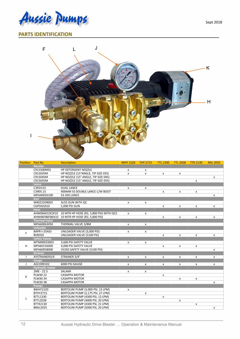
PARTS IDENTIFICATION
F
I
J L
H
Position Part No Description WHY 1520 THY 2715 TTL 1330 TTL 2028 TTK 2130 RAL 2035 Nozzles
C915500MSS HP DETERGENT NOZZLE x x C915035M HP NOZZLE (15°ANGLE, TIP SIZE 035) x x x x C915045M HP NOZZLE (15° ANGLE, TIP SIZE 045) x
C915055M HP NOZZLE (15° ANGLE, TIP SIZE 055) x Lance C3924.01 DUAL LANCE x x C3905.15 900MM SS DOUBLE LANCE C/W BOOT x x x MPA40026100 S3-350 LANCE x Gun M4022209003 AL55 GUN WITH QC x x CGPDG5010 5,000 PSI GUN x x x x Hose AHW06M22X2X10 10 MTR HP HOSE (R2, 5,800 PSI) WITH QCS x x AHW06FB6FB6X10 10 MTR HP HOSE (R2, 5,800 PSI) x x x x
Thermal Valve MPA60063050 THERMAL VALVE 3/8M x x Unloader
F BAPR-I-25ADJ UNLOADER VALVE (3,000 PSI) x x BVB350 UNLOADER VALVE (5100 PSI) x x x x
Safety Valves
H MTM00033003 3,600 PSI SAFETY VALVE x x MPA60156000 4,000 PSI SAFETY VALVE x x x MPA60058000 VS350 SAFETY VALVE (5100 PSI) x
Strainer I AYSTRAINER3/4 STRAINER 3/4” x x x x x x Gauge J AGCDR0102 6000 PSI GAUGE x x x x x x Hydraulic motor
K
2ME - 22.5 SALAMI x x PLM30 22 CASAPPA MOTOR x PLM30 34 CASAPPA MOTOR x x PLM30 38 CASAPPA MOTOR x
Pumps
L
BWHY1520 BERTOLINI PUMP (3,000 PSI, 13 LPM) x BTHY2715 BERTOLINI PUMP (2,175 PSI, 27 LPM) x BTTL1330 BERTOLINI PUMP (4300 PSI, 13 LPM) x BTTL2028 BERTOLINI PUMP (4000 PSI, 20 LPM) x BTTK2130 BERTOLINI PUMP (4300 PSI, 21 LPM) x BRAL2035 BERTOLINI PUMP (5000 PSI, 20 LPM) x
K
Aussie Hydraulic Drive Blaster … Operation & Maintenance Manual 13
Sept 2018
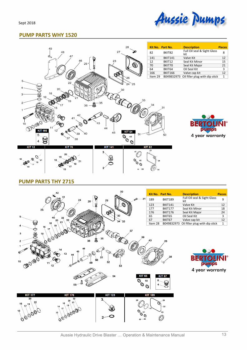
PUMP PARTS WHY 1520
Kit No. Part No. Description Pieces
82 BKIT82 Full Oil seal & Sight Glass kit 8
141 BKIT141 Valve Kit 12 12 BKIT12 Seal Kit Minor 15 70 BKIT70 Seal Kit Major 21 64 BKIT64 Oil Seal Kit 3 166 BKIT166 Valve cap kit 12 Item 29 B049832973 Oil filler plug with dip stick 1
PUMP PARTS THY 2715
Kit No. Part No. Description Pieces
189 BKIT189 Full Oil seal & Sight Glass kit 9
123 BKIT141 Valve Kit 12 177 BKIT177 Seal Kit Minor 18 176 BKIT176 Seal Kit Major 24 65 BKIT65 Oil Seal Kit 3 67 BKIT67 Valve cap kit 12 Item 28 B049832973 Oil filler plug with dip stick 1
Aussie Hydraulic Drive Blaster … Operation & Maintenance Manual 14
Sept 2018
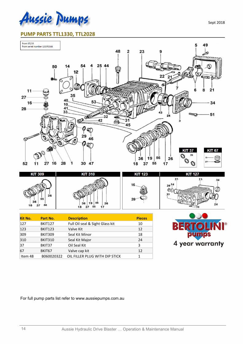
Kit No. Part No. Description Pieces
127 BKIT127 Full Oil seal & Sight Glass kit 10
123 BKIT123 Valve Kit 12
309 BKIT309 Seal Kit Minor 18
310 BKIT310 Seal Kit Major 24
37 BKIT37 Oil Seal Kit 3
67 BKIT67 Valve cap kit 12
Item 48 B060020322 OIL FILLER PLUG WITH DIP STICK 1
PUMP PARTS TTL1330, TTL2028
For full pump parts list refer to www.aussiepumps.com.au
Aussie Hydraulic Drive Blaster … Operation & Maintenance Manual 15
Sept 2018
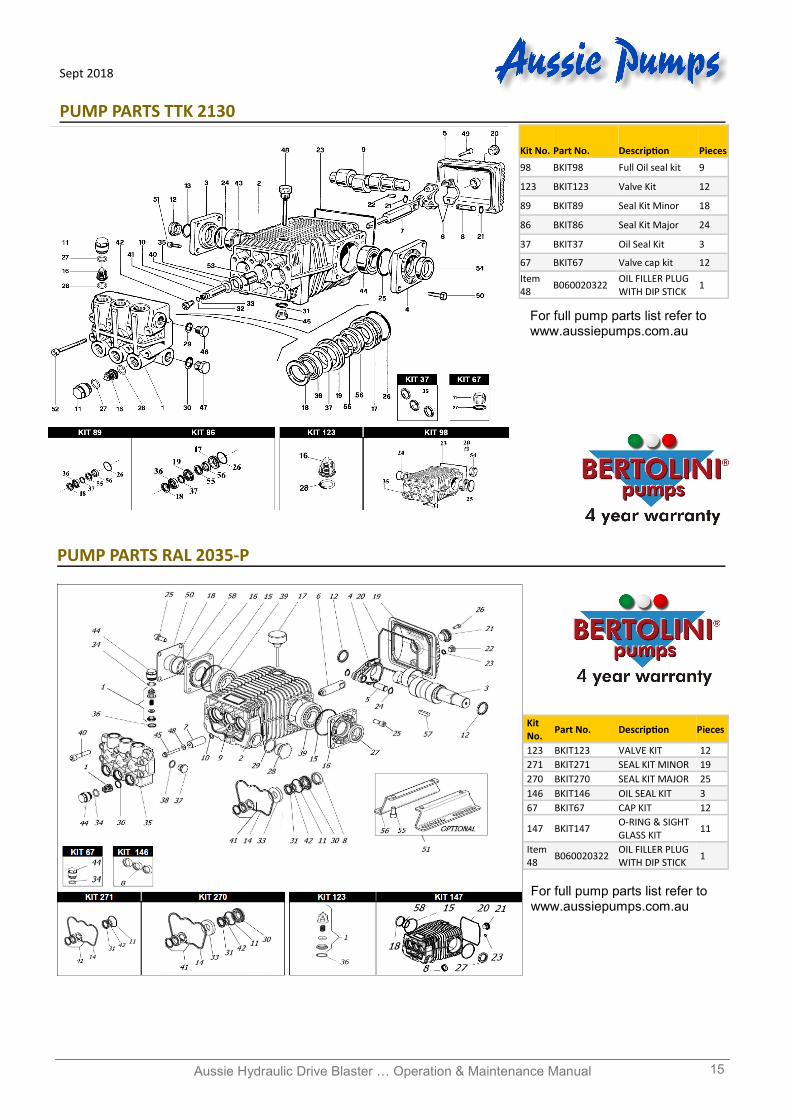
PUMP PARTS TTK 2130
PUMP PARTS RAL 2035-P
Kit No.
Part No. Description Pieces
123 BKIT123 VALVE KIT 12
271 BKIT271 SEAL KIT MINOR 19
270 BKIT270 SEAL KIT MAJOR 25
146 BKIT146 OIL SEAL KIT 3
67 BKIT67 CAP KIT 12
147 BKIT147 O-RING & SIGHT GLASS KIT
11
Item 48
B060020322 OIL FILLER PLUG WITH DIP STICK
1
Kit No. Part No. Description Pieces
98 BKIT98 Full Oil seal kit 9
123 BKIT123 Valve Kit 12
89 BKIT89 Seal Kit Minor 18
86 BKIT86 Seal Kit Major 24
37 BKIT37 Oil Seal Kit 3
67 BKIT67 Valve cap kit 12
Item 48
B060020322 OIL FILLER PLUG WITH DIP STICK
1
For full pump parts list refer to www.aussiepumps.com.au
For full pump parts list refer to www.aussiepumps.com.au
OVERSPEEDING
Do not operate machine at over the maximum
rpm. Over speeding can cause serious pump
damage.
EXCESSIVE BYPASS
Do not run on excessive by-pass. Switch
machine off within five minutes of ceasing
operation as excessive by-pass can cause heat
build up in pump and subsequent damage.
Excessive bypass running voids warranty.
HIGH PRESSURE SETTING
The high pressure pump is factory set to operate
at its rated pressure. DO NOT ADJUST.
Tampering with the pressure regulator will void
warranty and can be DANGEROUS.
CHECK NOZZLE MONTHLY
If pressure drops off check nozzle for wear.
Nozzles should be replaced on a regular basis
(every month for machines in regular use, every
three months for machines used intermittently).
Using the machine with the incorrect nozzle size
or worn nozzle will void warranty and can be
DANGEROUS to the operator.
PRESSURE CLEANER DAILY CHECK LIST Check pump oil level
Check nozzle for wear
Check all HP components for leaks: Gun/lance, HP
hose and all fittings
Check water filter and clean if necessary
Check unloader & safety valve for leaks
THREE MONTHLY REGULAR SERVICE
All professional machines need to be thoroughly
serviced every three months. The service should
include the following; Change pump oil
Check filter for foreign debris
Check unloader & safety valve for leaks
Check all HP components for leaks: Gun/lance, HP
hose and all fittings
Replace nozzles
SIX MONTHLY REGULAR SERVICE
To maintain the Bertolini pump warranty (three years
from date of purchase), the pump must be serviced by
an authorised service agent every six months. Contact
Aussie for your nearest agent.
LOOK AFTER YOUR MACHINE AND IT WILL LOOK AFTER YOU!
Australian Pump Industries Pty Ltd 7 Gladstone Road, Castle Hill NSW 2154 Ph: (02) 8865 3500 Fax: (02) 9894 4240 www.aussiepumps.com.au [email protected]
WARNINGS